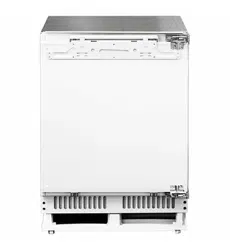

AINT7600**
INSTALLATION &
OPERATION MANUAL
APPLIANCES
FOR LIVING

Congratulations, you are now the proud owner of an ARTUSI cooking appliance. Thank you for purchasing ARTUSI
and welcome to the ARTUSI Family.
This instruction manual has been specially created to inform you of the full range of features your ARTUSI appliance
has to offer and serves as an introduction to getting the very best out of your ARTUSI appliance.
We present detailed information on each of the features your ARTUSI appliance consists of. Once you have read
this section you will be able to choose the most appropriate settings for your appliance when cooking different types
of food.
We ask you to read the instructions in this booklet very carefully as this will allow you to get the best results from
using your appliance. KEEP THE DOCUMENTATION OF THIS PRODUCT FOR FUTURE REFERENCE.
TO REGISTER YOUR PRODUCT WITH ARTUSI, PLEASE FILL OUT THE WARRANTY CARD AT THE END OF
THIS BOOKLET AND POST IT TO:
REPLY PAID 83617
LEICHHARDT NSW 2040
Dear Artusi Customer, please read this user manual carefully before using the product and, keep it permanently at
your disposal.
Note: This user manual is prepared for more than one model. Some of the features specified in this Manual may not
be available on your appliance.
All our appliances are only for domestic use, not for commercial use. Products marked with (*) are optional.
“THIS APPLIANCE SHALL BE INSTALLED IN ACCORDANCE WITH THE REGULA TIONS FORCE AND ONLY
USED IN A WELL VENTILATED SPACE. READ THE INSTRUCTIONS BEFORE INSTALLING OR USING THIS
APPLIANCE”
“Conforms with the WEEE Regulations.”

AINT7600**
INSTALLATION
GUIDE

2
TABLE OF CONTENTS
Symbols and Their Meanings ......................................................................................................................................... . 4
Installation Place..............................................................................................................................................................7
Tool list............................................................................................................................................................................10
ALTERNATIVES FOR INSTALLATION ................................................................................................................................11
PREPARATION FOR INSTALLATION .................................................................................................................................12
Cabin Dimensions ...........................................................................................................................................................12
Location of the Electrical Wiring.....................................................................................................................................13
Location of the Water System ........................................................................................................................................14
Production dimension ……............................................................................................................................................ 16
Unpacking .......................................................................................................................................................................23
Removing Connectors on the rear Wall .........................................................................................................................25
Removing Mounting Parts in the Freezer Compartment ...............................................................................................26
Removing the Freezing Crisper.......................................................................................................................................27
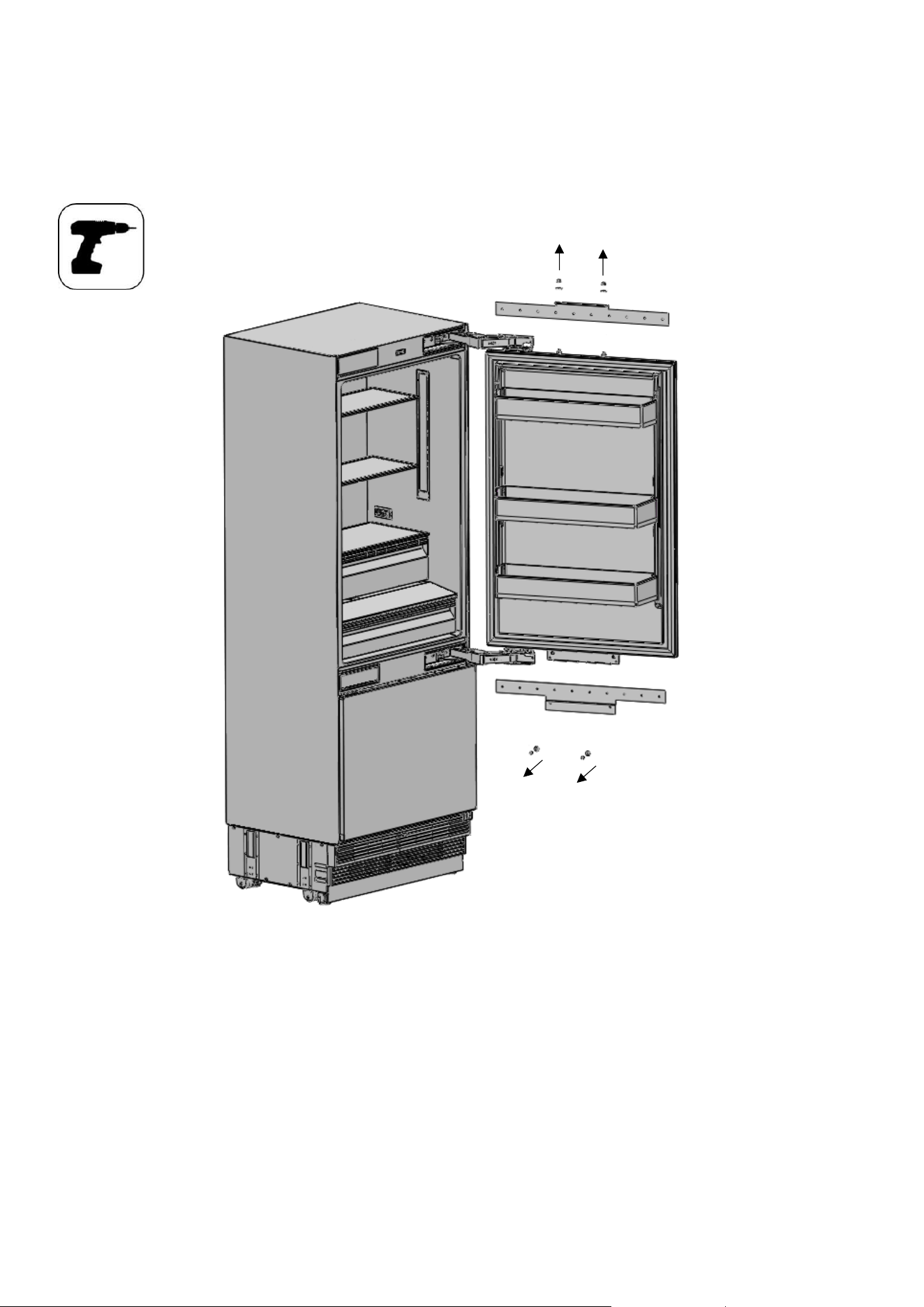
Attaching the upper vent hole part ................................................................................................................................47
Attaching the lower vent hole assembly
Removing the Freezing Door ..........................................................................................................................................28
Removing the Lower Vent Hole Assembly..................................................................................................................... 29
Removing the Upper Vent Hole Part ..............................................................................................................................29
PRE-INSTALLATION .........................................................................................................................................................30
Mounting the Anti-Tip Brackets .....................................................................................................................................30
Alternative anti-tip method............................................................................................................................................33
Preparing the Water Hose and the Power Plug..............................................................................................................34
INSTALLATION TO THE CABIN .........................................................................................................................................35
Taking the Refrigerator from the Wooden Pallet...........................................................................................................35
Placing the refrigerator into the cabin ...........................................................................................................................36
Adjusting the height of the refrigerator in the cabin .....................................................................................................39
Adjusting the refrigerator according to the cabin flange ...............................................................................................40
Screwing the Cabinet-cabin connecting bracket............................................................................................................43
INSTALLING THE CABIN BOTTOM ...................................................................................................................................45
Water connection ...........................................................................................................................................................45
.......................................................................................................................48
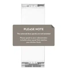
Attaching the decorative parts .......................................................................................................................................49

3
CHANGING THE DIRECTION OF THE FF DOOR ....................................................................................................................72
Removing the fridge furniture door ...............................................................................................................................72
Removing and preparing the Fridge Inner Door.............................................................................................................76
Replacing the hinges.......................................................................................................................................................78
Installing the fridge door ................................................................................................................................................
HINGE ADJUSTMENT...........................................................................................................................................................71
Adjusting the hardness of the hinges .............................................................................................................................
FURNITURE DOOR PREPARATION......................................................................................................................................52
Removing the Mechanism Covers ..................................................................................................................................52
Removing the Panel-Adjustment Mechanisms on the Refrigerator ..............................................................................53
Preparing Furniture Door................................................................................................................................................54
Preparing the Furniture Door .........................................................................................................................................55
Preparing the freezer Furniture Door.............................................................................................................................57
Installing the Fridge Furniture Door ...............................................................................................................................59
Installing the Freezing Furniture Door............................................................................................................................65
71
82
INSTALLATION DUAL CABIN................................................................................................................................................83
Cabin dimensions............................................................................................................................................................83
Location of the electrical wiring .....................................................................................................................................84
Location of the water system .........................................................................................................................................85
mounting part lists..........................................................................................................................................................86
Attaching the fasteners and connecting bracket ...........................................................................................................87
Adjusting the height of the refrigerator in the cabin .....................................................................................................89
Screwing the bracket furniture on the cabin side wall...................................................................................................90
Screwing the bracket furniture on the cabin top wall....................................................................................................90
Attaching the decorative parts .......................................................................................................................................91
4
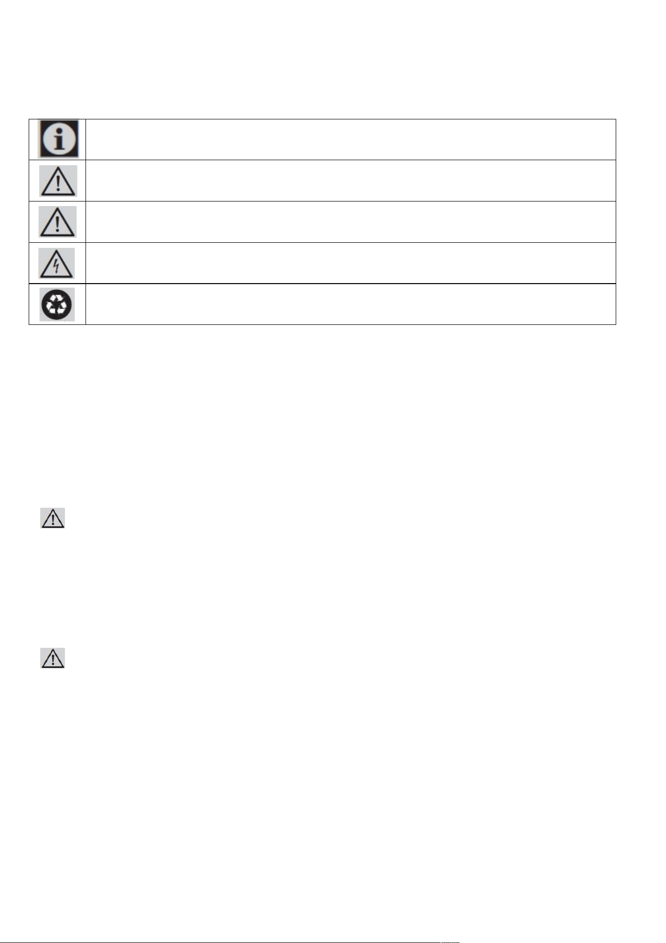
Symbols and Their Meanings
Symbols used in the installation manual are as follows.
Important information or useful usage tips
WARNING: Conditions that may damage the product or its operating functions
ATTENTION: Conditions containing serious injury risk
Conditions containing electric shock risk
Packaging materials of the product have been manufactured from recyclable materials in
accordance with our National Environment Regulations.
Disposing the packaging materials
The package has been designed to protect the product during transport.
The packaging materials used for the product do not harm the nature during disposal and
they need to be recycled.
All plastic packaging materials, bags etc. must be disposed safely and kept out of the reach of children.
Please return the packaging to your dealer.
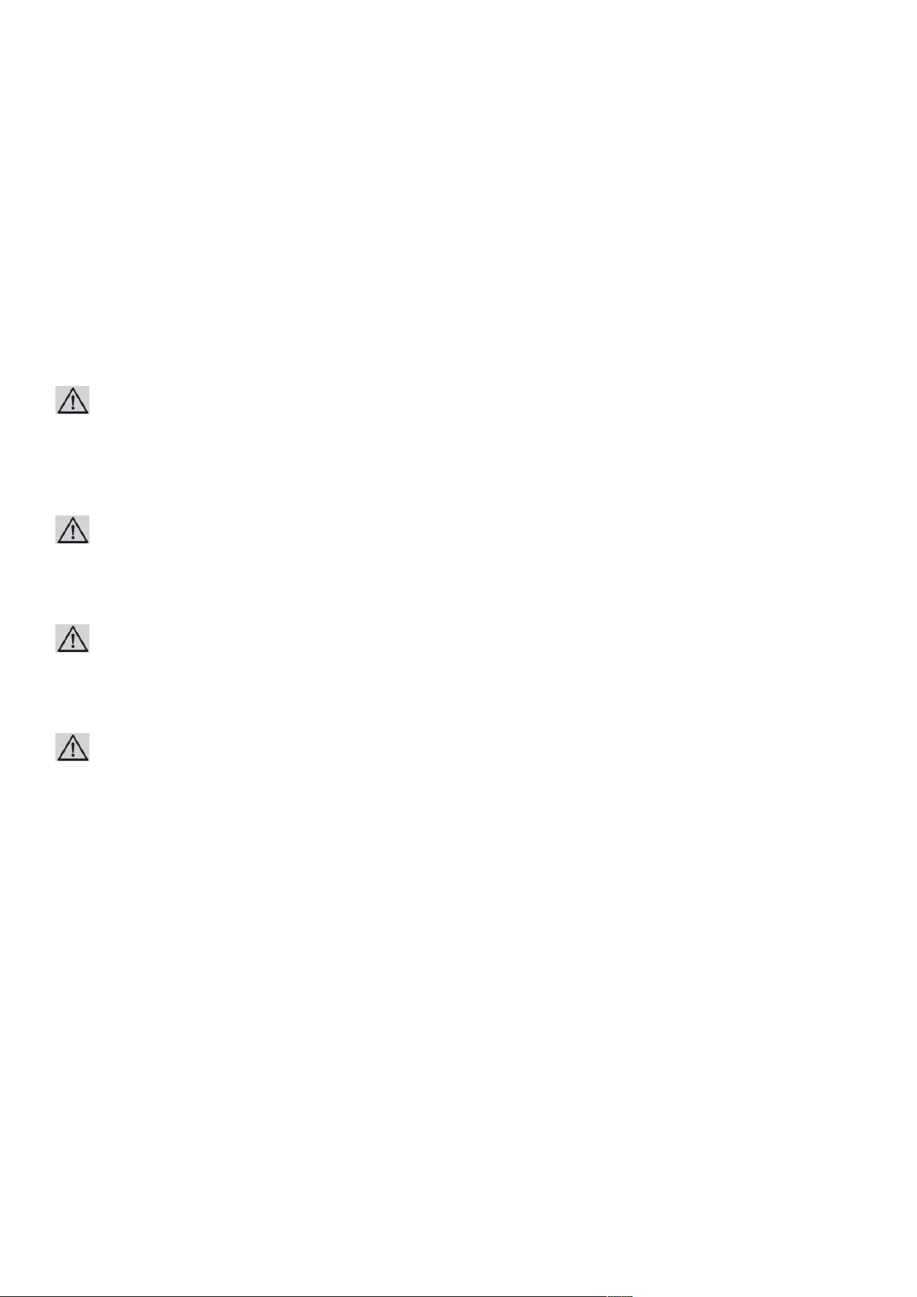
WARNING:
This installation manual has been prepared to help installation teams. The User Manual provided with the product
must also be taken into consideration.
You may get seriously injured and your product may get damaged if you ignore the warnings given in this manual.
Please read the following carefully.
WARNING:
R600a Refrigerant
This product contains R600a isobutane refrigerant, which is a very eco-friendly natural gas. However, it is also
flammable. Please follow the warnings given below:
• If the product has been transported horizontally, you must wait for 4 hours minimum before plugging it in.
• The following instructions must be followed during installation:
• Dimensions of the installation area must be suitable.
• Dimensions, features and position of the object used to support and fix the product to this area must be
suitable.
5
• Minimum clearances between product parts and surrounding structures must be suitable.
• Minimum dimensions and proper organisation of ventilation holes must be observed.
• The product must be connected to the mains power,
and corresponding connections of other components must be suitable.
• The product must be able to be disconnected from the power supply after installation.
• The socket or fuse must be accessible to de-energise the product.
• Extension cables or ungrounded (two-terminal) adapters must not be used.
ATTENTION:
You must wear gloves and eye protectors when installing the product.
You must also take measures against high noise levels when drilling the floor or using a drill.
ATTENTION:
Make sure that your product is suitable for your local mains.
ATTENTION:
The product must be installed by a qualified technician according to the installation instructions.
WARNING:
The product may tip over since it is quite heavy. For this reason, precautions must be taken against tipping over.
The doors of the product must be kept closed until it reaches the destination and it must be transported
in accordance with the installation instructions.
6
Product weight:
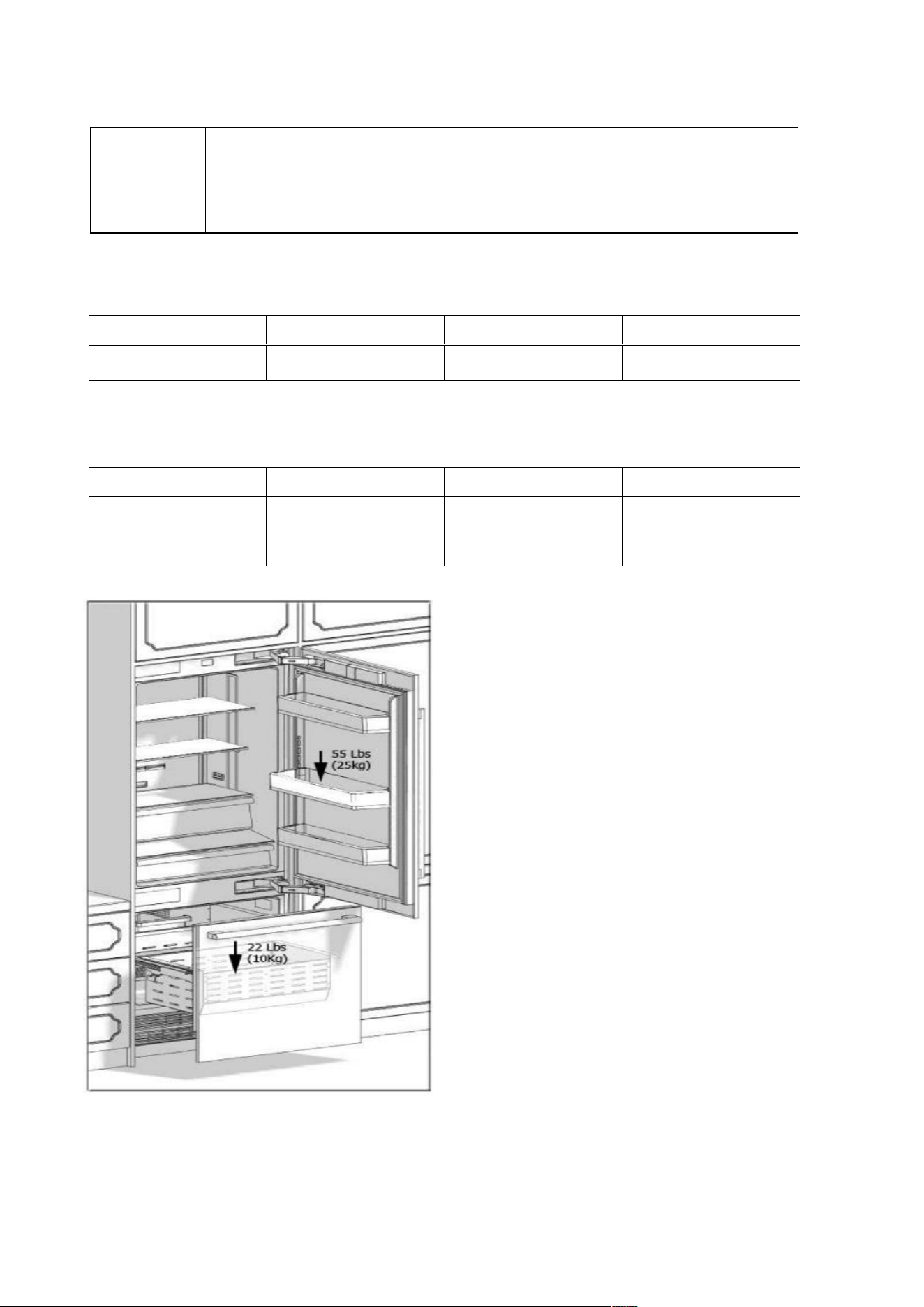
Load bearing capacity of the doors
Climate range Ambient temperature of the room
This appliance has been designed to
be used in certain climate ranges
(ambient temperatures). It must not
be used out of this range.
SN
N
ST
T
Between +50
o
F (10
o
C) and +90
o
F (32
o
C)
Between +60
o
F (16
o
C) and +90
o
F (32
o
C)
Between +60
o
F (16
o
C) and +110
o
F (38
o
C)
Between +60
o
F (16
o
C) and +120
o
F (43
o
C)
Category
AINT7600/AINT7600IW AINT9000/AINT9000IW
Product weight 361Ibs (164kg) 373Ibs (169kg)
Max load
AINT7600/AINT7600IW AINT9000/AINT9000IW
Fridge door
55Ibs (25kg)
55Ibs (25kg)
Freezer door
22Ibs (10kg)
22Ibs (10kg)
TRF-76BINFIA
TRF-91BINFIA
AINT7600/AINT7600IW
AINT9000/AINT9000IW

7
Installation Place
You must follow the instructions below:
• The floor on which the product will be installed must be capable of bearing 1,200 pounds (544 kg) minimum.
• Kitchen floor and the bottom of the product must be at the same level. Otherwise, problems may occur with
the air suction of the product.
• There must be no objects preventing the installation of the product at the back and on the side walls of the
product's installation place.
• The power socket must be at the correct place.
• Dimensions of the furniture where the product will be installed must be in strict conformity with the
dimensions given in the manual.
• Do not install the product with the fridge and the freezer are adherent next to each other. Otherwise,
condensation and damage may occur in the product. (Please see "Dual Cabin Installation" for detailed
information)
• Flatness of the floor where the product will be installed must be checked with a Bubble Level Tool.
• Installation area must not be subjected to direct sunlight and it must be away from heat sources, ovens,
radiators etc.
• The ambient temperature must be between 55°F (13°C) and 110°F (43°C). Otherwise,
• function errors may arise when the product is running.
• If it is not possible to avoid installing the product near a heat source, the minimum clearances given below must
be maintained between the product and the said source:
• 11/4" (3 cm) from electric hobs or ovens 1 1/4”
• 12" (30 cm) from gas or fuel operated hobs or ovens
Please observe the following rules:
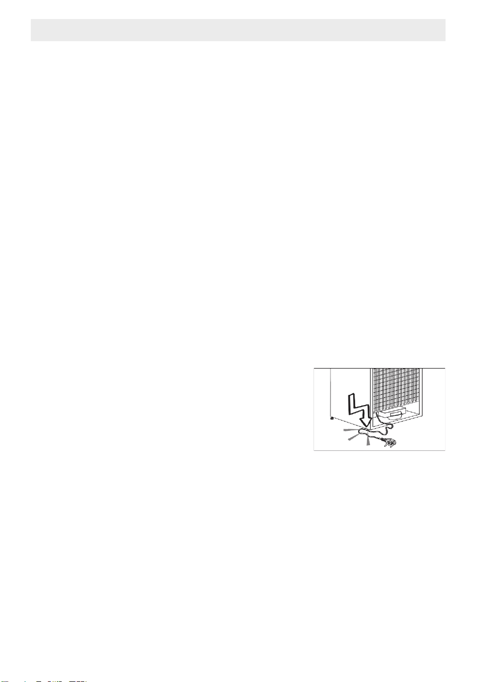
• The power socket or fuse must be easily accessible in case of an emergency;
it must not be hidden behind the product.
• Plug or cable must not touch the back surface of the product. Otherwise,
it may get damaged due to the vibration of the product.
• Do not connect the plugs of other appliances behind this product.
If the humidity level is high where the product is used, corrosion may be seen
on the outer surface of the product.
Keep the installation room dry and well-cleaned to avoid corrosion.

8
To avoid the risk of electric shock:
• Connect the plug to a grounded 3-pin socket.
• Do not remove the ground terminal of the plug.
• Do not use adapters.
• Do not use extension cables.
ATTENTION:
Failure to follow these instructions may result in death, fire or electric shock. Connecting the grounding conductor of
the equipment to an improper place may lead to electric shock. Please have the grounding checked by a qualified
electrician or service technician if you have any doubt about the proper grounding of the product.
Installation, repair and other procedures performed by unqualified persons may cause danger. Before installing the
appliance, make sure that the voltage, load and circuit current parameters on the data plate are in compliance with
the power mains in your house.
The appliance is provided with a NEMA 5-15 P plug and a 3-pin power cable which is in the UL list and ready to be
connected to a 120 V, 60 Hz power supply. Fuse is 15 A. The appliance must be connected to a 3-pin socket. The plug
must be installed only by a licensed electrician.
If the electrical wiring or the electric power supply of the house needs alteration, the necessary procedures must be
performed by a qualified electrician.
ATTENTION:
Do not install your refrigerator:
• In open areas
• In environments where water is dripping
• In environments where temperature is lower than 55° F (0°C)
Furniture:
Make sure that the furniture where you will install the appliance has been safely mounted in your kitchen.
Your furniture must be connected to the floor and the wall properly and with suitable connections.
For the best installation, clearances between the furniture and the product must be in compliance
with the values specified in the installation instructions.
Side walls must be free of clearances and their surfaces must be flat.
Minimum thickness of the side walls must be 5/8" (16 mm).
Minimum thickness of the doors to be attached to the product must be ¾" (19 mm) .
ATTENTION:
There is a stainless steel door and stainless kick plate option. Please consult the authorised service.

9
Ventilation:
Vent holes where the air enters and exits the unit must not be blocked or obstructed. In addition, you must
periodically clean the dust and dirt that accumulate on these holes in time.
Electrical Connection:
• Never use an extension cable.
• The power socket must definitely be grounded and checked by an authorised person.
• Location of the electrical wiring must comply with the dimensions specified in the manual.
ATTENTION:
RISK OF ELECTRIC SHOCK
Electrical grounding is necessary. This appliance is equipped with a three-pin plug
to protect you against possible electric shocks.
• Do not remove the round grounding terminal from the plug.
• Do not use two-pin grounding adapters.
• Do not use extension cables to energise the product.
ATTENTION:
Do not connect the grounding cable to the gas pipe. Please have the grounding checked by a qualified electrician if
you are not sure about the grounding of the product. Do not install a fuse on the neutral line or grounding circuit.
WARNING:
Please wait for 3-6 hour before energising the product to protect it against possible damages. This way, the
refrigerant and the lubricants in the system get balanced.
Water Connection
• Pressure of the mains water must be in compliance with the values specified in the manual.
• Location of the water system must comply with the dimensions specified in the manual.
IMPORTANT INFORMATION:
Bypass is recommended for the water filtering system if a reverse osmosis system is used.
10
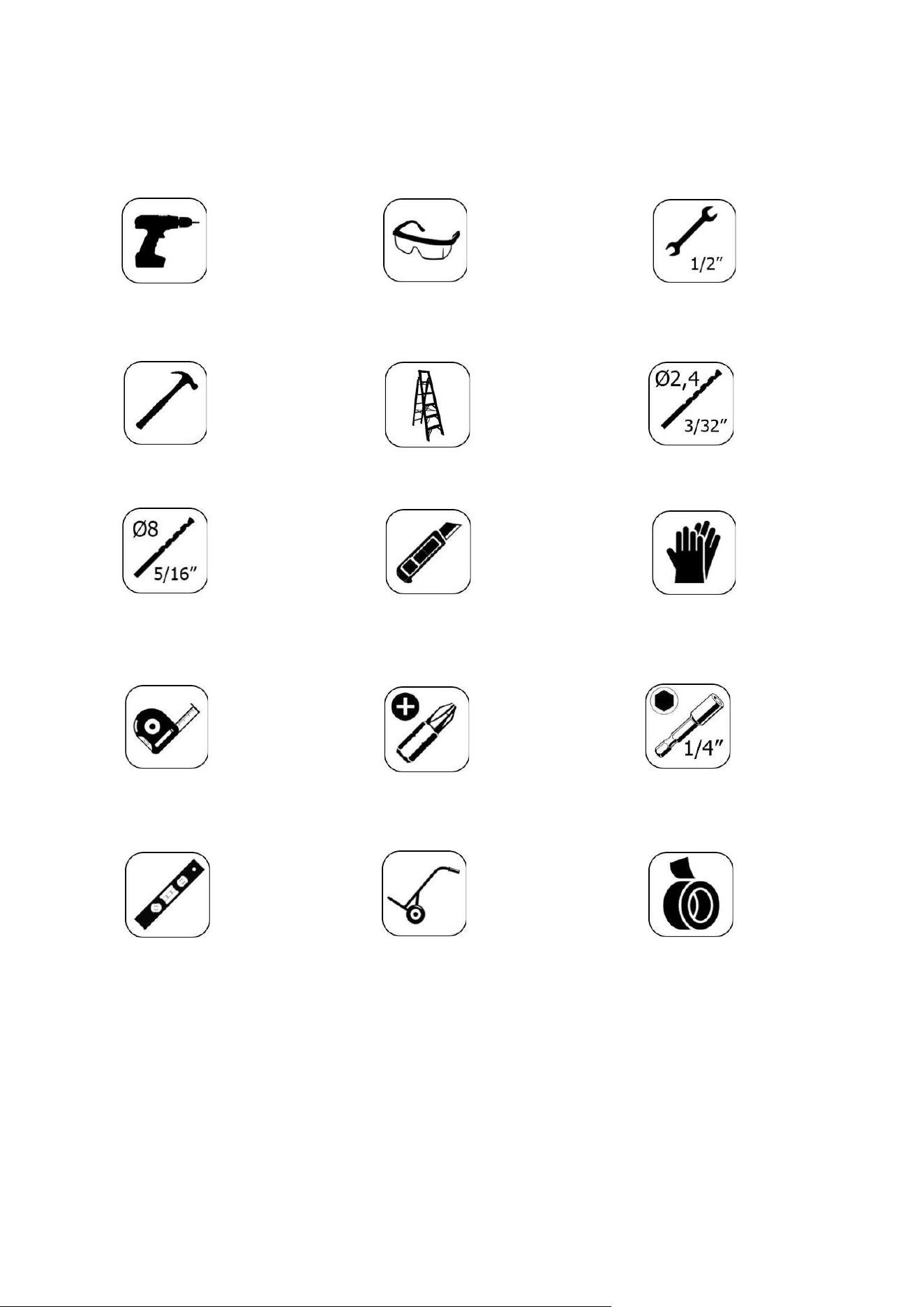
TOOL LIST
Tools to be used when installing the product are as follows:
Cordless
Drill
Safety
Goggles
½"
Wrench
Hammer
Ladder Ø2.4
Drill bit
Ø8.0
Drill bit
Box
Cutter
Safety
Gloves
Tape
measure
Star bit
¼"
Wrench Flat
Bubble
Level
Tool
Wheelbarrow
Tape
11
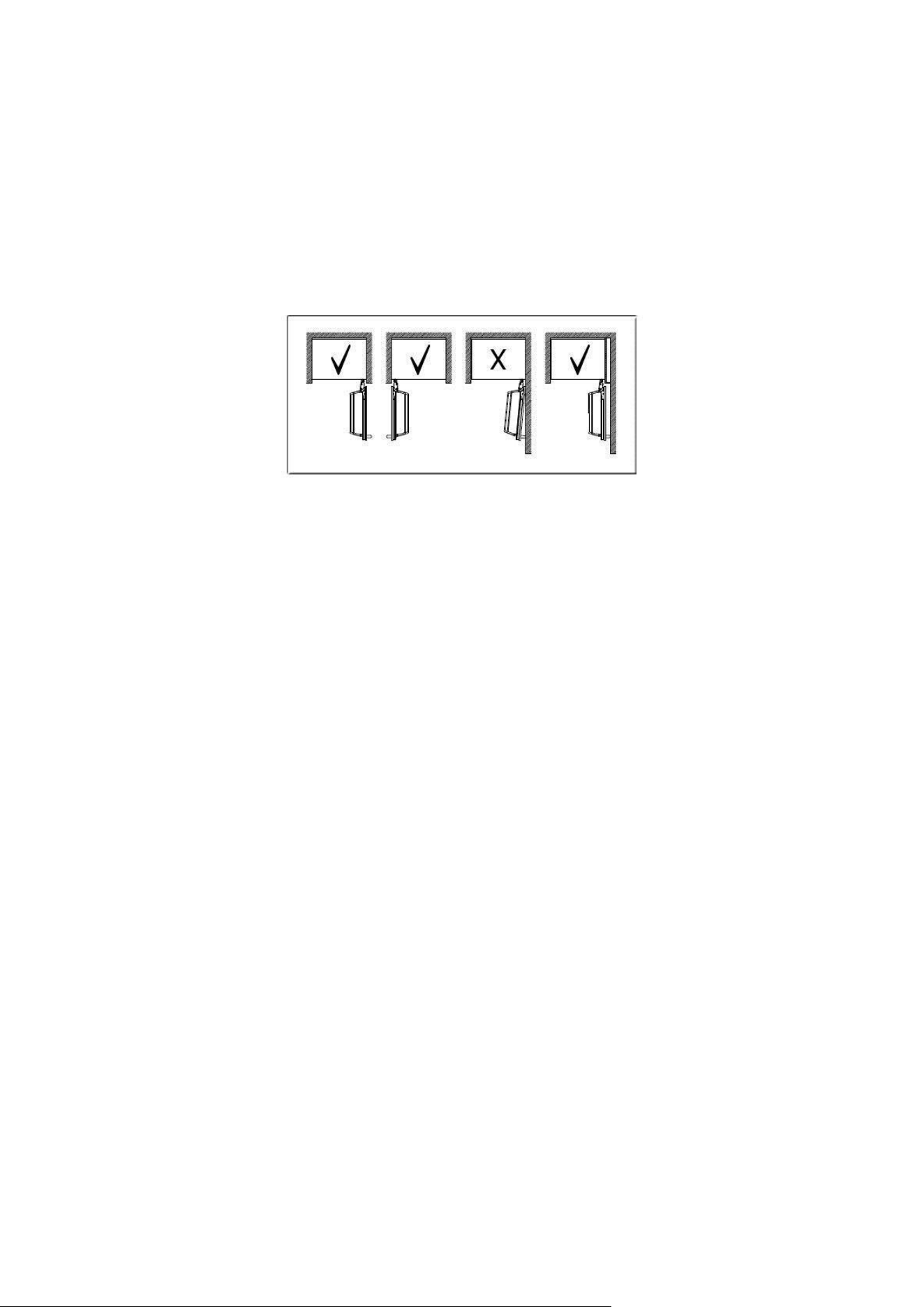
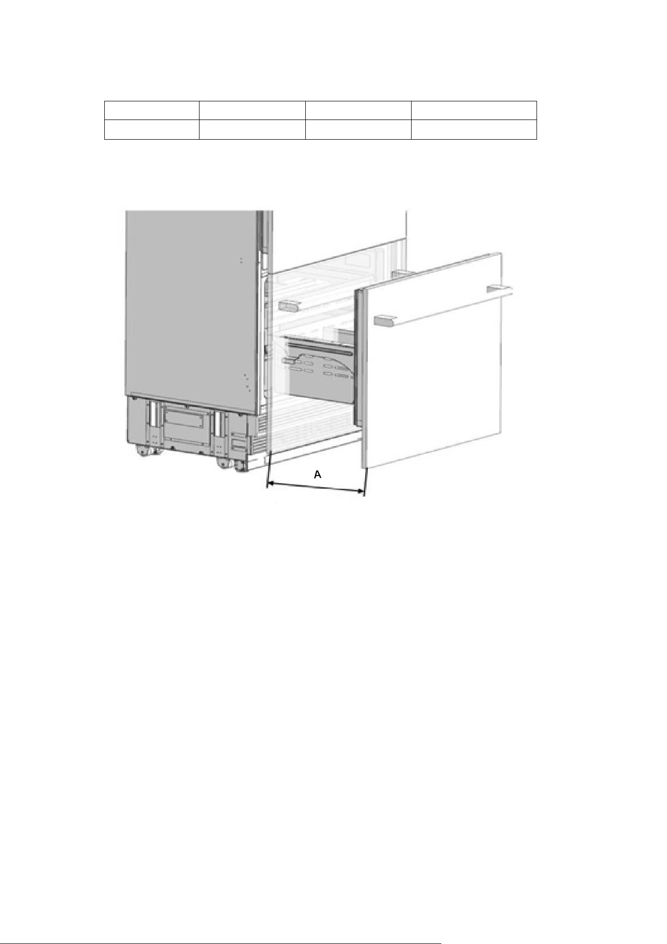
ALTERNATIVES FOR INSTALLATION
The product can be placed in various ways based on the kitchen design. It must be installed at a place where it is
ensured that the door can be opened and closed properly. If the doors cannot be opened 90 degrees at least, you
cannot completely open the drawers inside the product.
• Single cabin placement methods
12
PREPARATION FOR INSTALLATION
The instructions below have been prepared according to Built-in type.
Built-in: The Appliance and Panels fully seat into the gap, and a material that can be their own box is jammed
between the two kitchen cabinets or decorative columns.
This is the most common installation scenario.
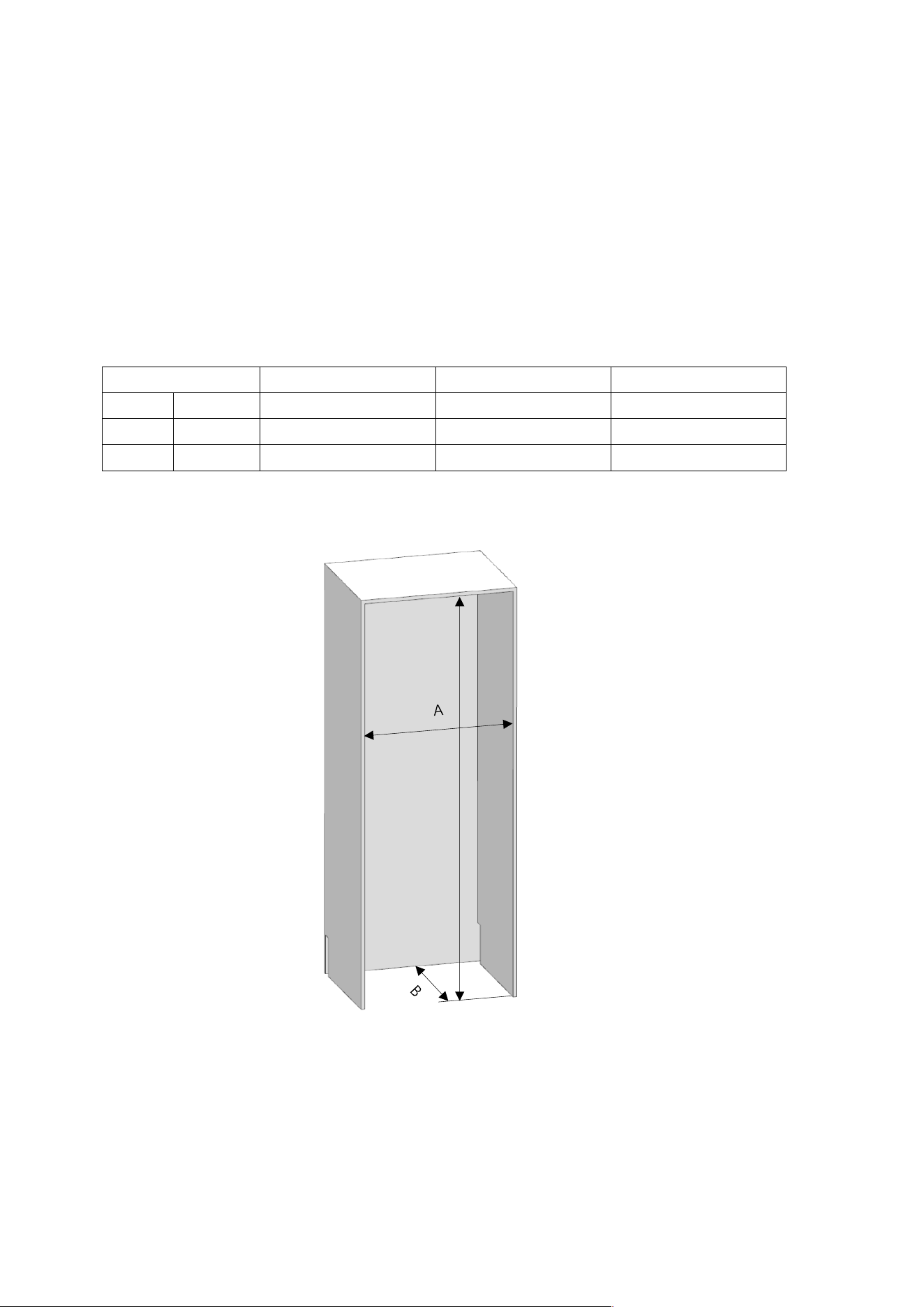
Cabin Dimensions
• Cabin dimensions below must be checked before starting the installation.
Category AINT7600/AINT7600IW
AINT9000/AINT9000IW
A width 30" (762mm) 36" (914mm)
B depth 25" (635mm) 25" (635mm)
C height 84" (2134mm) 84" (2134mm)
C
13
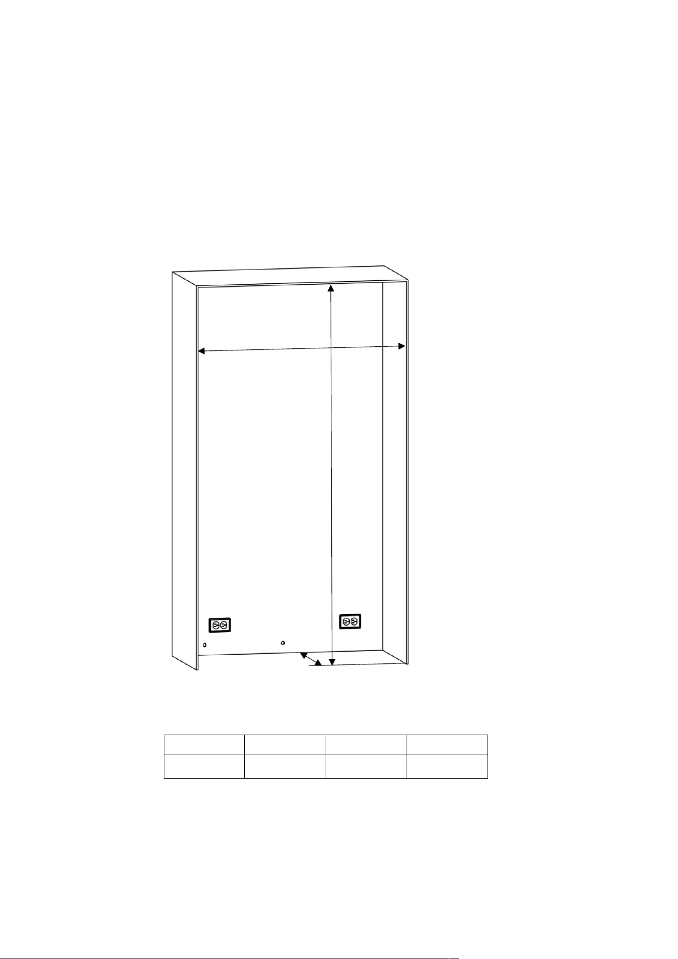
Location of the Electrical Wiring
Location of the electrical wiring must be within the range given below.
ATTENTION:
Do not use extension cables or two-pin adaptors and do not remove the ground terminal of the grounding cable.
ATTENTION:
A qualified electrician must ensure that the poles of the socket are connected correctly.
Verify that the grounding of the socket is correct.
14
Location of the Water System
The water connected to the water mains must be potable.
Location of the water system must be within the range given below.
Water system of the refrigerator must be connected to the water mains system in the house.
The user must be able to switch it on/off with the valve when necessary.
Objects that might pierce the water hoses or cause them to twist must not be present
where the water line is installed.
Pressure of the water system must be between 25-80 psi (1.7-5.5 Bar).
If the water pressure exceeds 80 psi, install a pressure limiting device or water impact protector to the inlet valve.
Never install the product or operate the appliance if it is possible for the water pressure to exceed 120 psi.
WARNING:
Make sure that there is no water leakage when making the water connections. Otherwise,
there will be water on the floor and the furniture will get damaged.
You will need a hose with a minimum length of 60" (1.5 meters) and a diameter of ¼"
for water connections of the product during installation.
A connector that has a thread with an external diameter of ¼ must be used to connect the hose end to the product.
Before completing the installation, make sure that water flows and there is no water leakage.
15
WARNING:
• Flatness of the floor where the product will be installed must be checked with a Bubble Level Tool.
• Uprightness of the furniture flanges must be checked with a Bubble Level Tool.
• If the flatness and uprightness of the product is not proper, problems may arise with the installation.
16
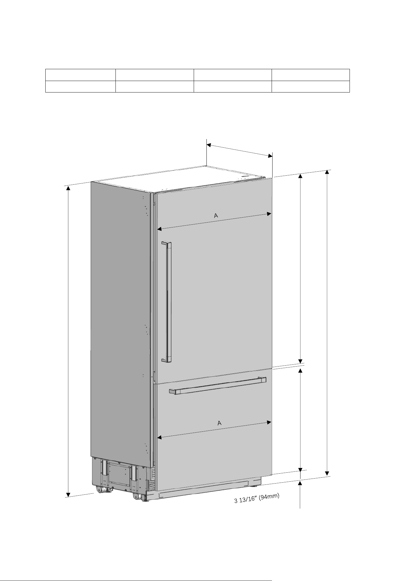
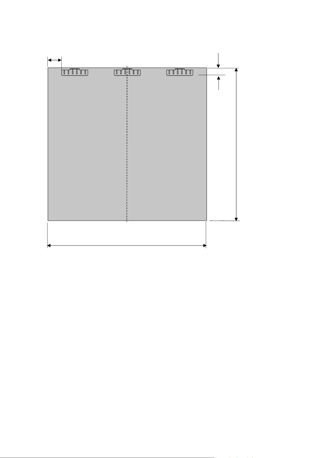
PRODUCT DIMENSION
Category
AINT7600/AINT7600IW
AINT9000/AINT9000IW
A 29 3/4” (756mm) 35 3/4” (908mm)
51 1/16” (1297mm)
28 11/16” (729mm)
83 9/16” (2123mm)
3
without panel : 23 5/16” (592mm)
with panel : 24 ¼” (616mm)
83 9/16” (2123)
17
Category
AINT7600/AINT7600IW
AINT9000/AINT9000IW
A
15 9/32" (388mm)
15 9/32" (388mm)
18
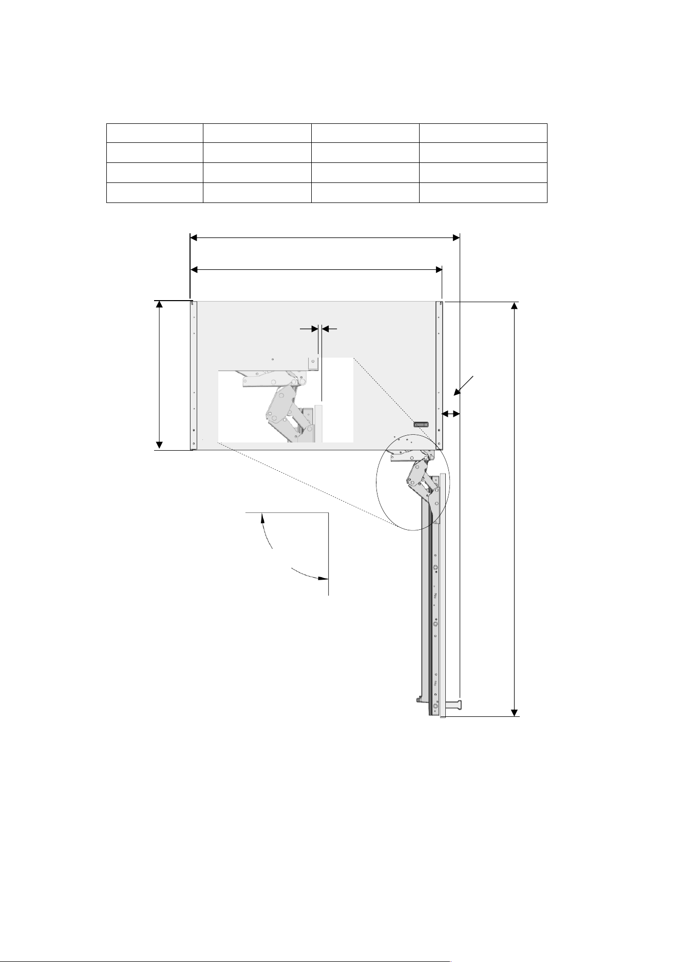
Category AINT7600/AINT7600IW AINT9000/AINT9000IW
A 32 7/16” (824mm) 38 7/16” (976mm)
B 29 3/4“ (756mm) 35 3/4“ (908mm)
C 55 1/32” (1398mm) 61” (1550mm)
21 27/32” (555mm)
2 11/16” (68mm)
90°Door swing
Minimum to wall
3/8” (10mm)
90
°
B
C
A
19
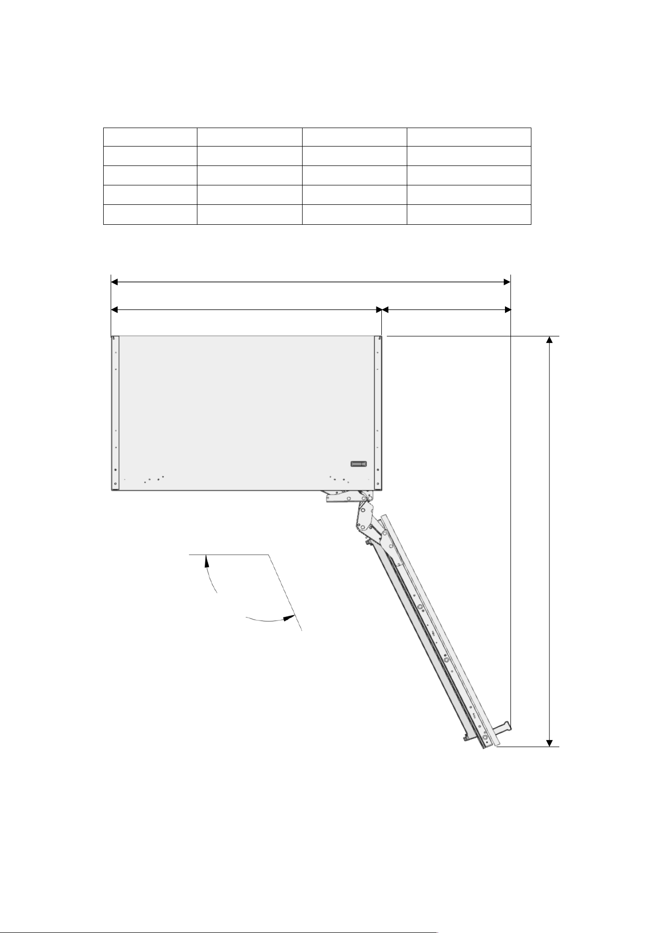
Category AINT7600/AINT7600IW AINT9000/AINT9000IW
A
443/8” (1127mm) 54 3/4” (1391mm)
B
29 3/4“ (756mm)
35 3/4“ (908mm)
C
14 5/8” (371mm)
19” (483mm)
D
52 11/16” (1338mm)
57 11/16” (1466mm)
115°Door swing
115°
A
C
D
B
20
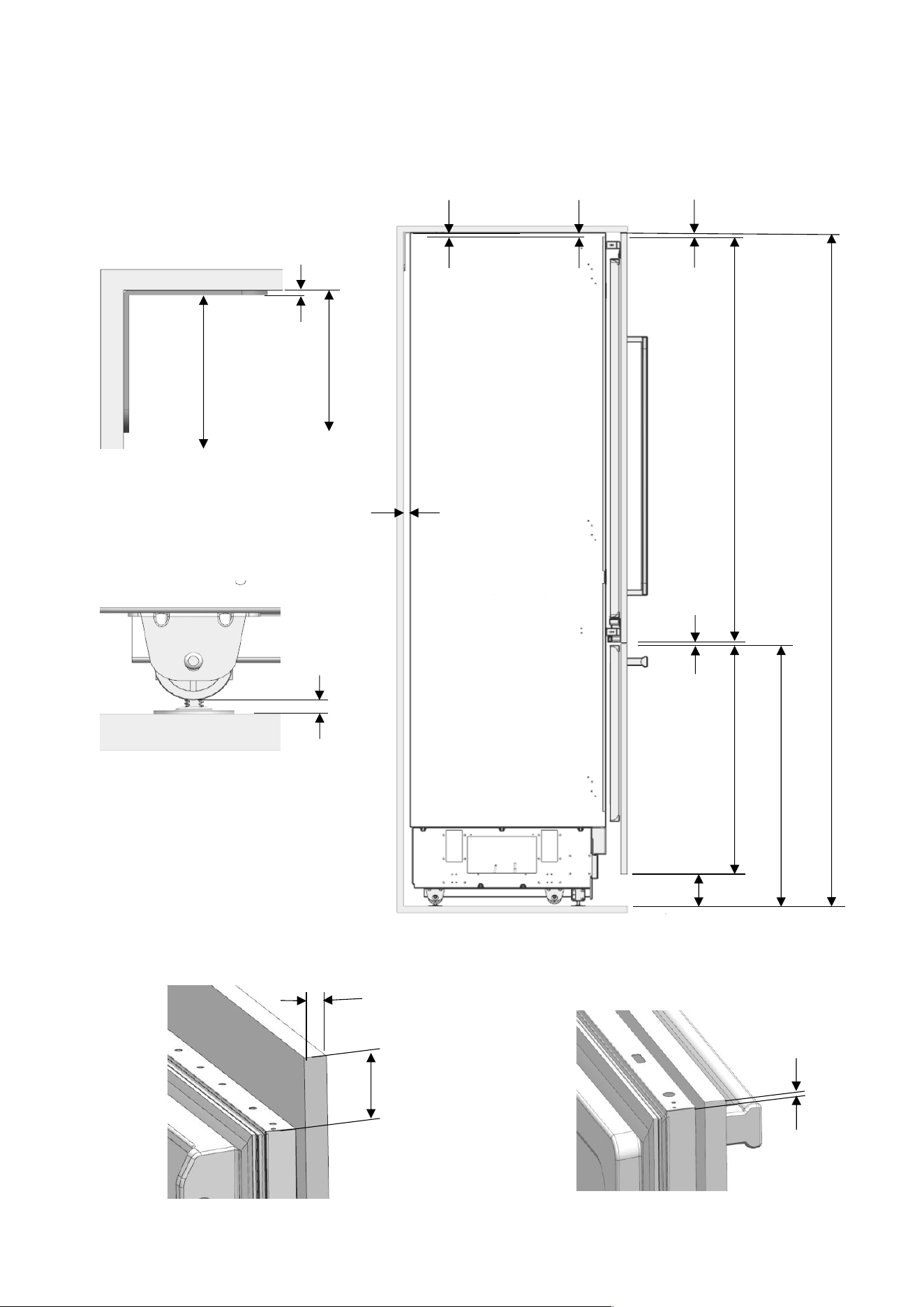
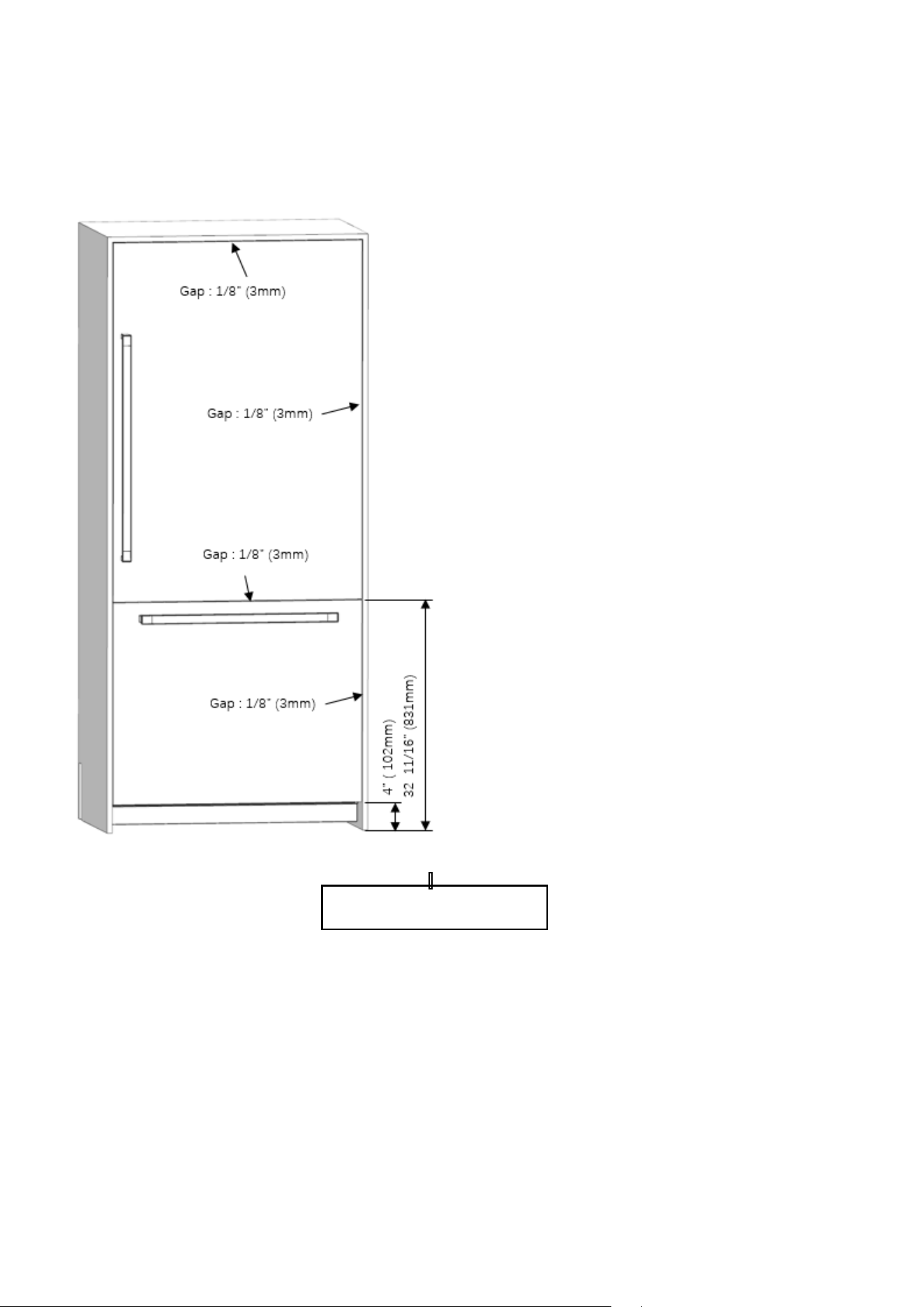
51 1/16” (1297mm)
28 11/16” (729mm)
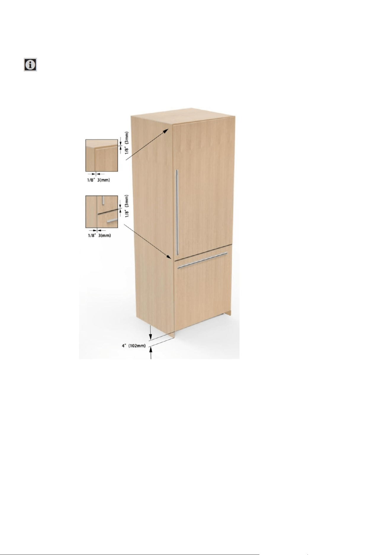
4” (102mm)
32 11/16” (831mm)
1/8” (3mm)
5/32” (4mm)
1/8” (3mm)
84” (2134mm)
1/8” (3mm)
3/4” (19mm)
Remaining space
after install
Minimum height
adjustment for leveling
Anti tip bracket location
5/32” (4mm)
84” (2134mm)
83 27/32” (2130mm)
Front 5/16” (8mm)
Rear ¼” (7mm)
Assembly dimension between
Wood panel and fridge door
4
”
(83mm)
3/4”
(19mm)
Assembly dimension between
Wood panel and freezer door
1/4” (6mm)
21
AINT7600/AINT7600IW
AINT9000/AINT9000IW
22
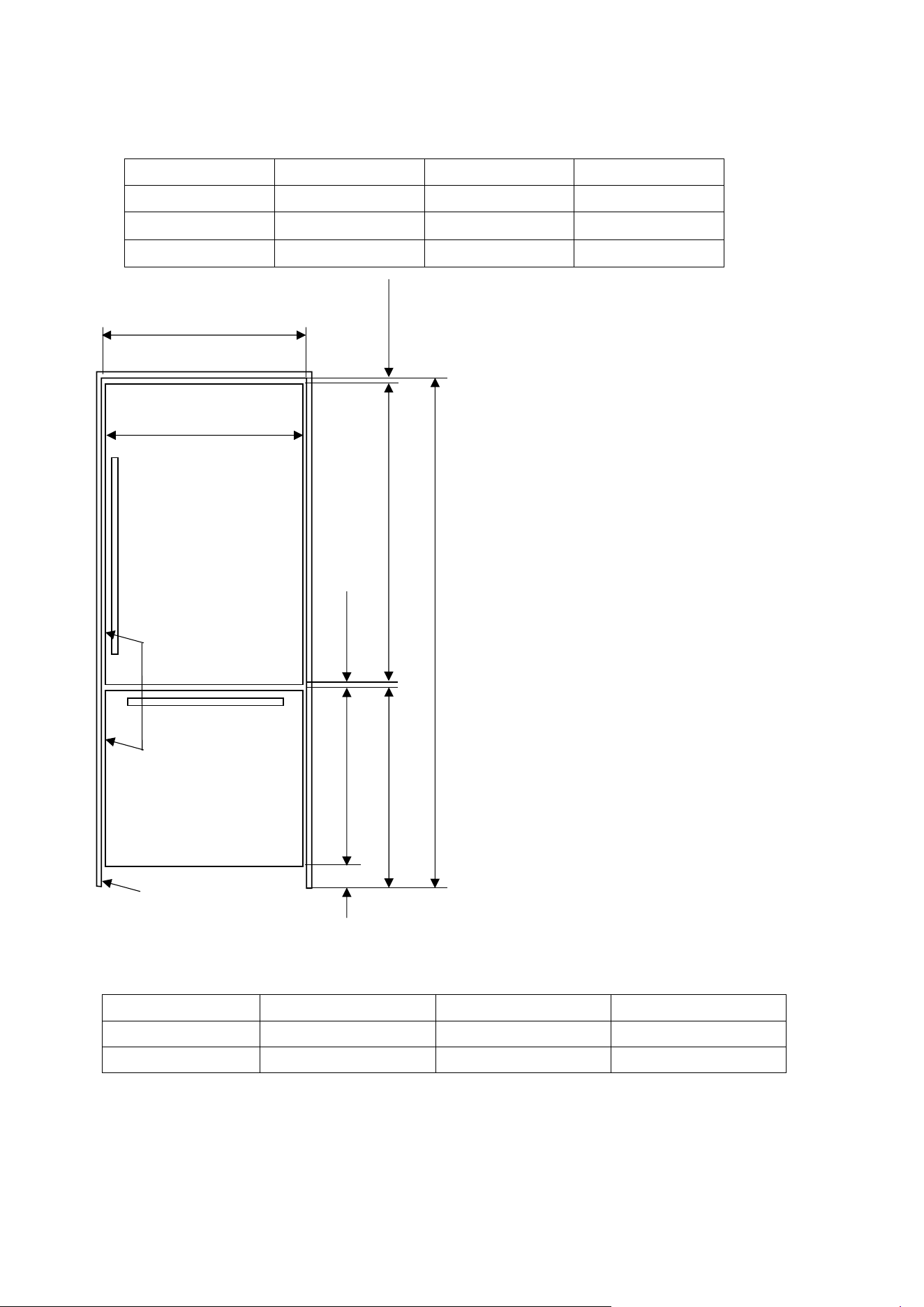
Height of the kitchen countertop based on the min/max. height of the cabin;
A B C
standard 4” (102mm) 32 11/16” (831mm) 84” (2134mm)
minimum 3 13/16”(97mm) 32 1/2“ (826mm) 83 13/16“ (2129mm)
maximum 5 3/8“(137mm) 34 1/8“ (866mm) 85 3/8“ (2169mm)
Category AINT7600/AINT7600IW
AINT9000/AINT9000IW
D
30” (762mm) 36” (914mm)
E
29 3/4” (756mm) 35 3/4” (908mm)
Freezer panel height
Furniture wood panel
Door wood panel
28 11/16” (729mm)
A
B
51 1/16” (1297mm)
1/8” (3mm)
C
1/8” (3mm)
Fridge panel height
D
E
23
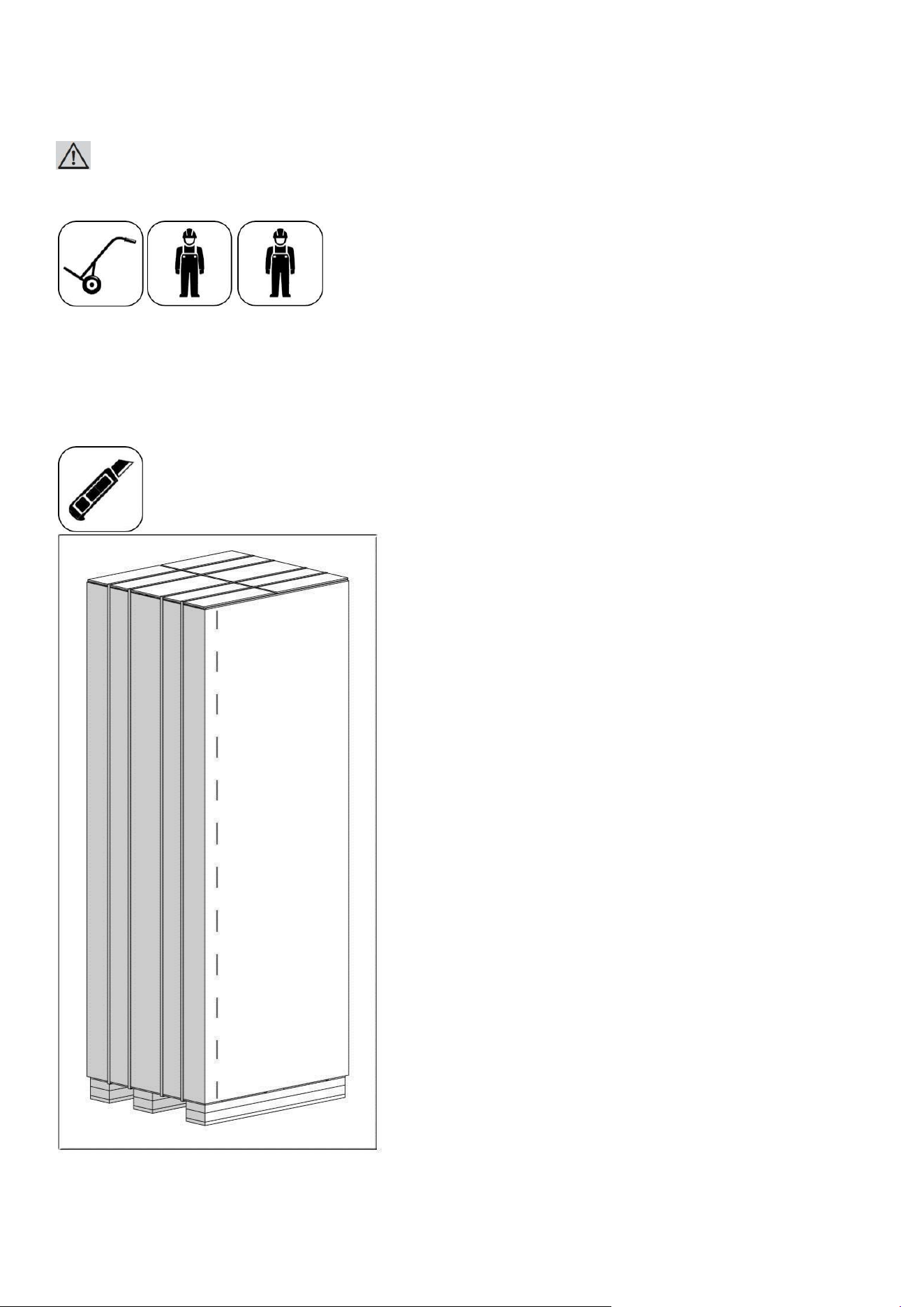
Unpacking
WARNING:
At least two persons must carry the refrigerator.
• Use a box cutter to remove the tapes.
• Cut the Packaging Board with a Box Cutter through the section illustrated in dotted lines
and remove it.
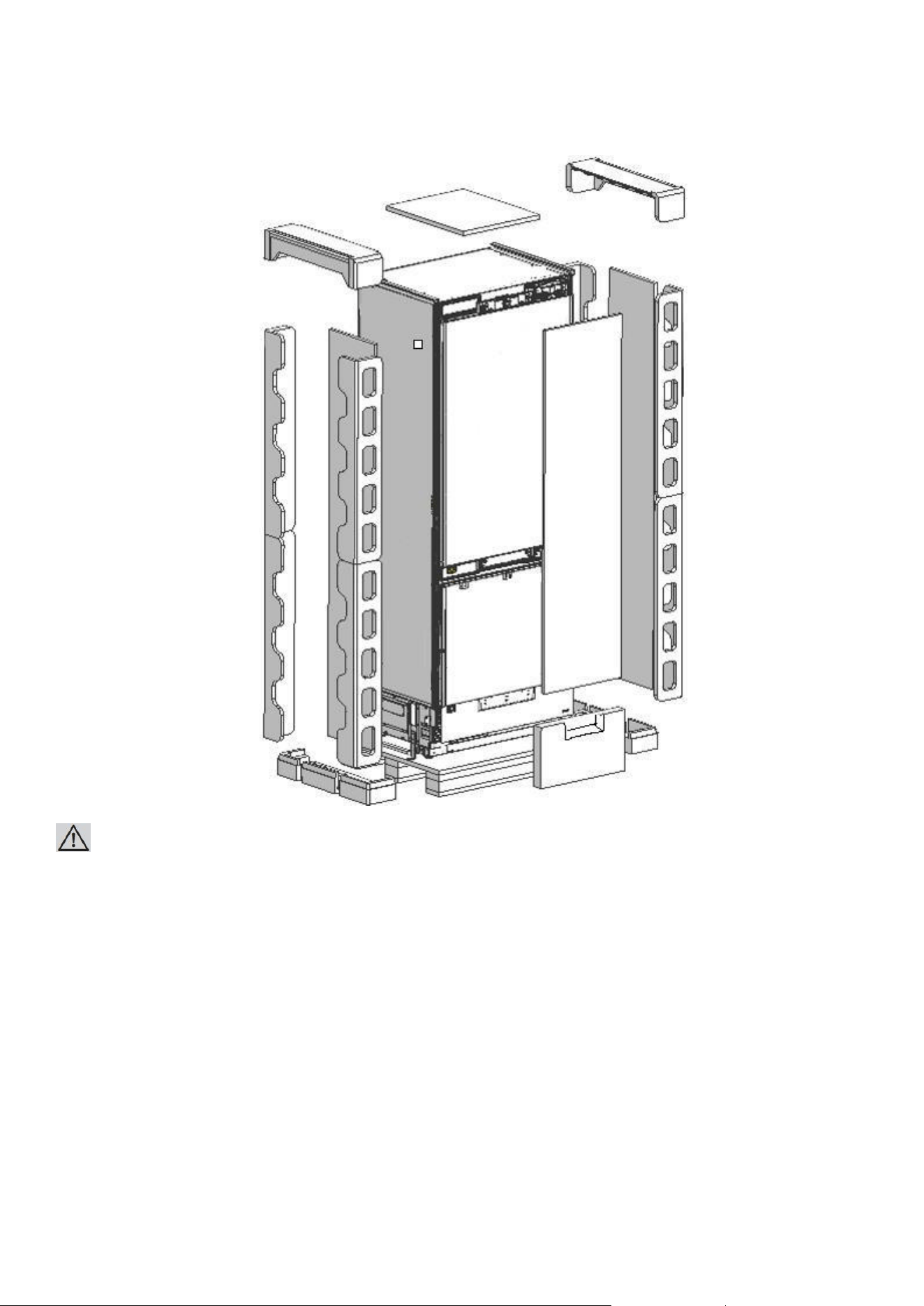
⚫ Remove the Packaging Polystyrene
24
material.
ATTENTION:
Do not remove the tape of the upper door on the product until the refrigerator is placed into the cabin.
Risk of tipping over.
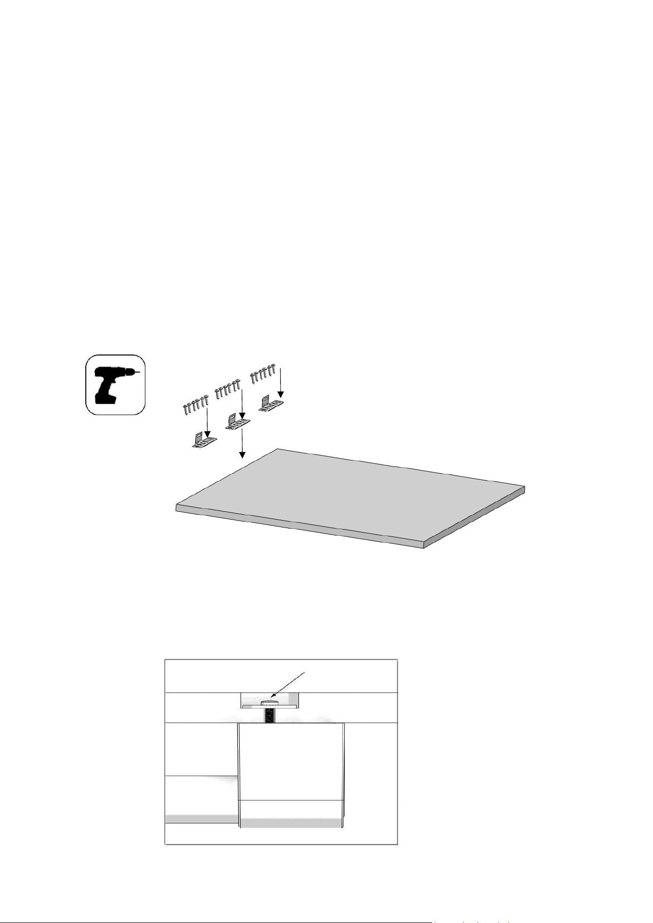
25
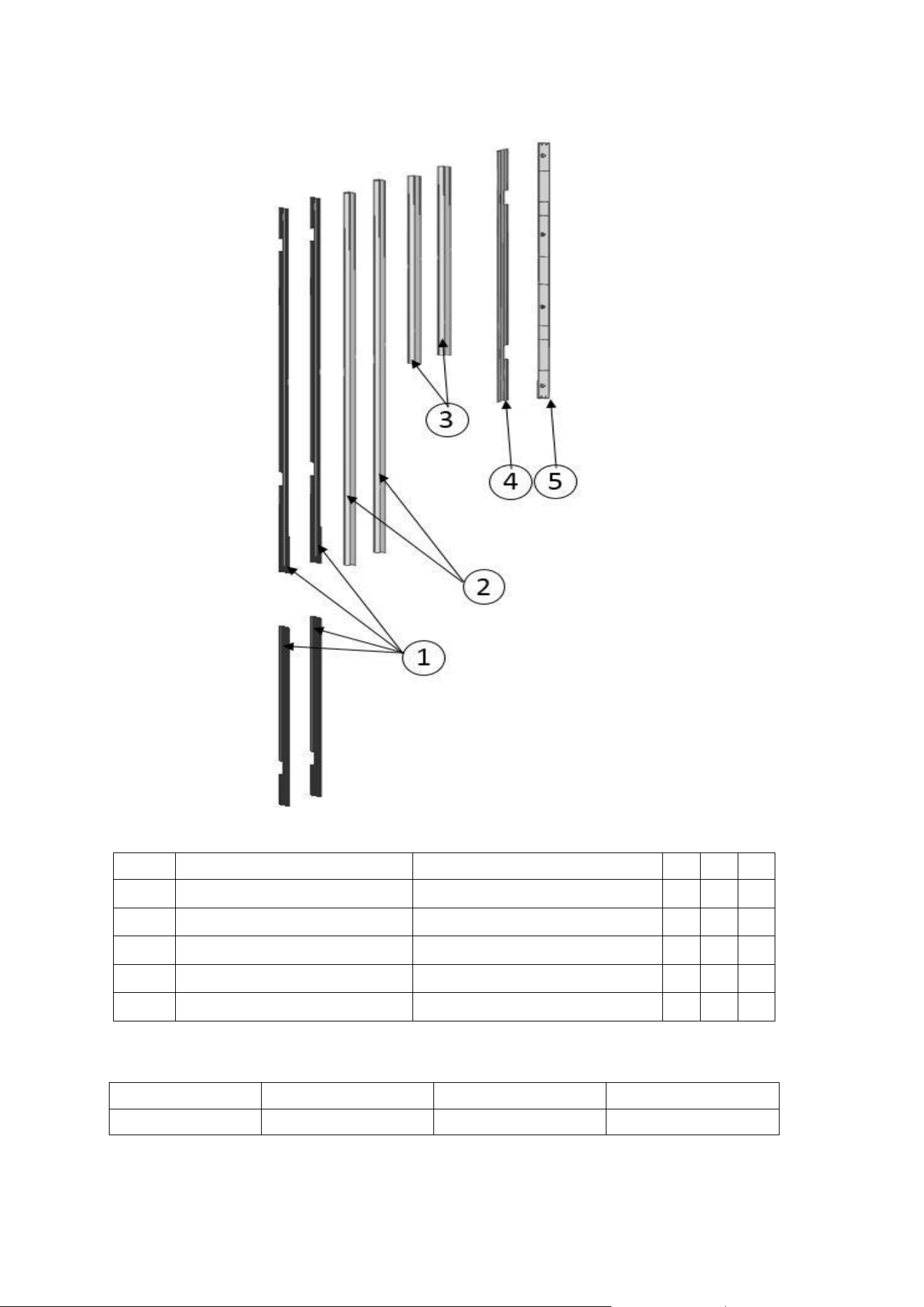
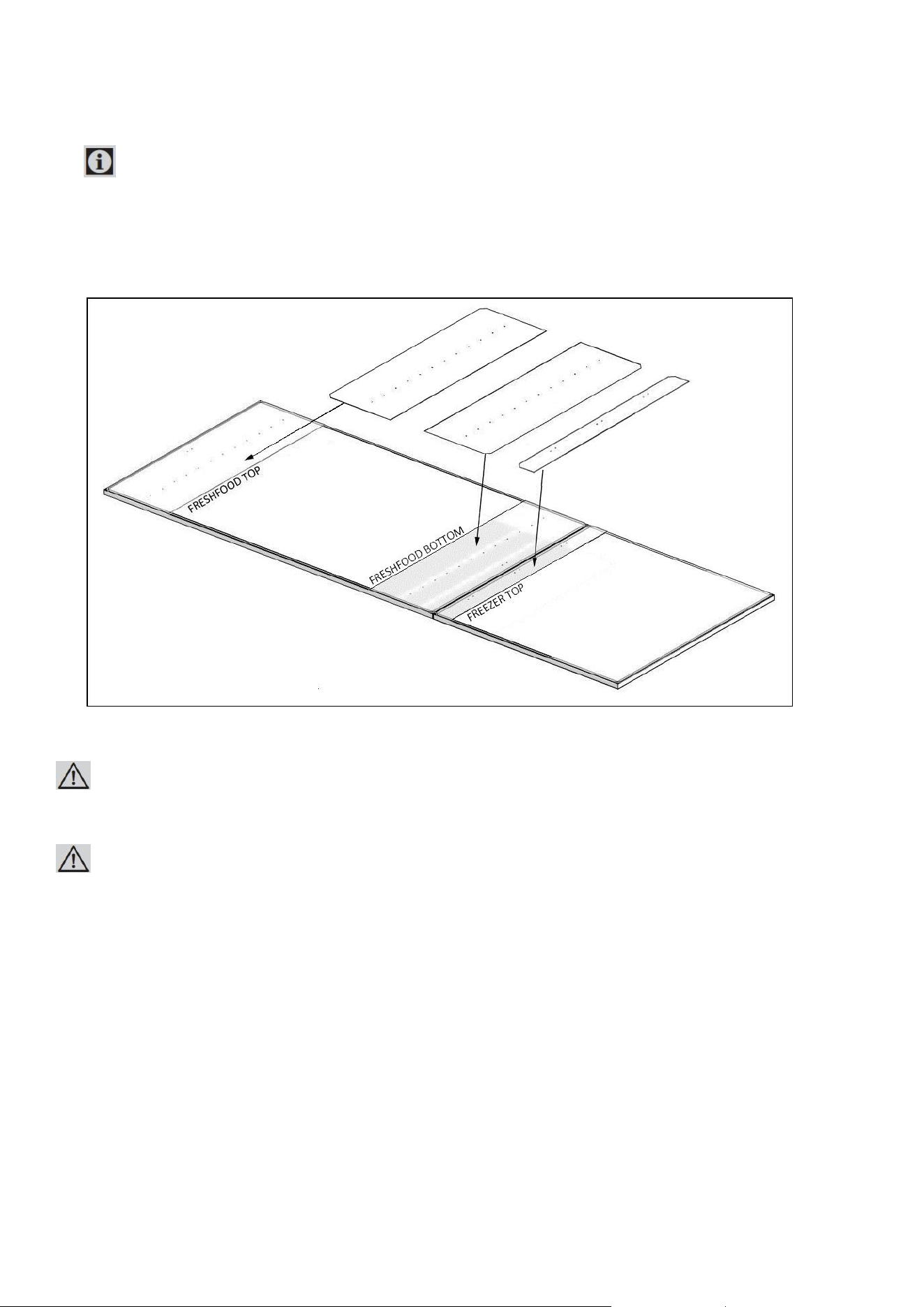
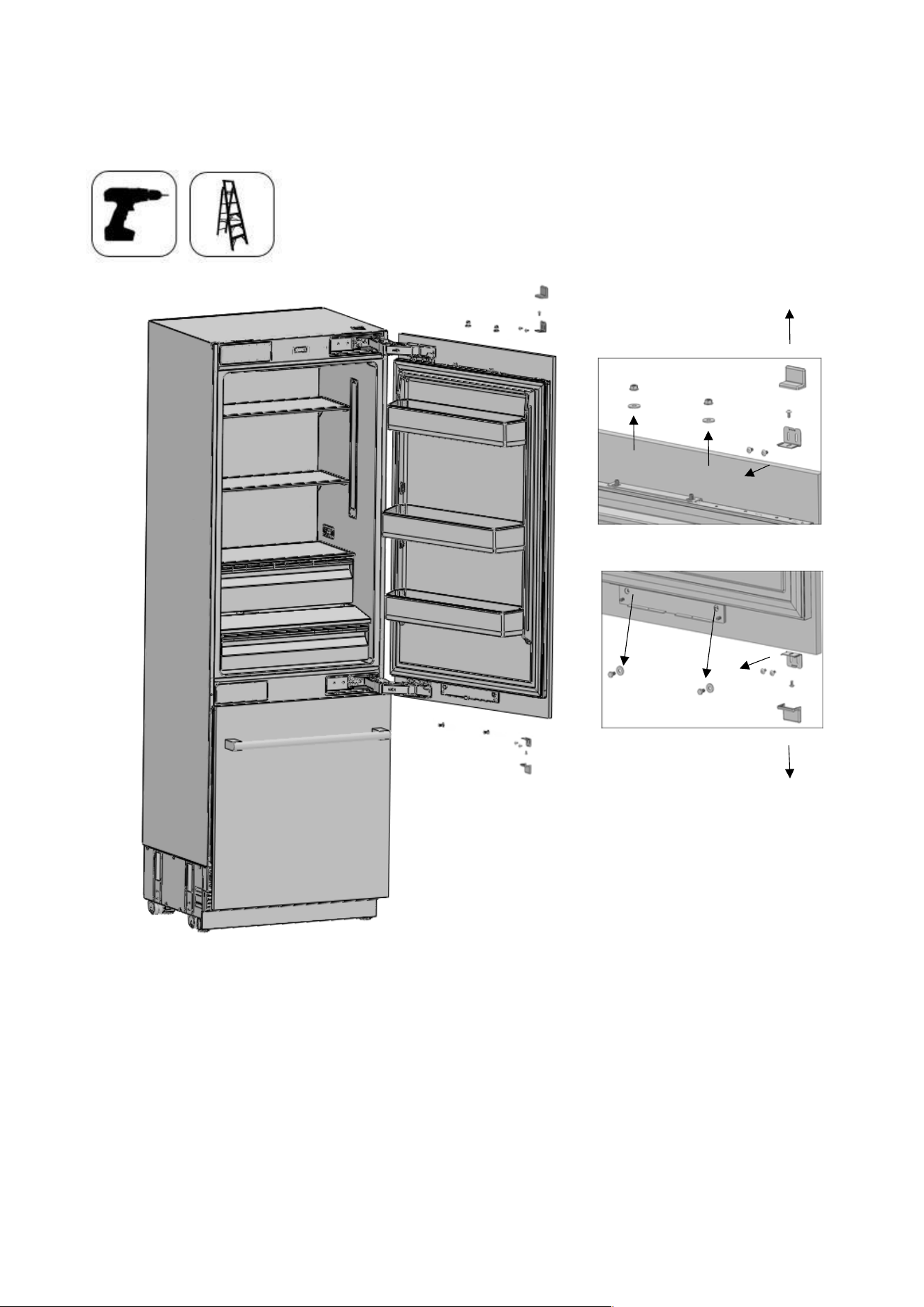
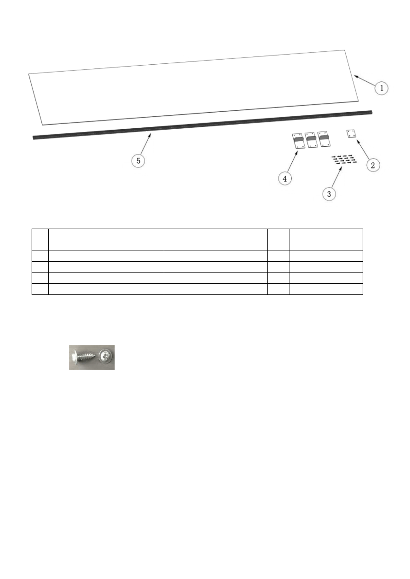
Removing connectors on the rear wall
√ Conference
No Part name spec 76 90
1 Trim fridge furniture side PVC extrusion L=617, L=1,259 4 4
2 Trim fridge door side PVC extrusion L=1136 2 2
3 Trim freezer door side PVC extrusion L=556 2 2
4 Trim furniture top PVC extrusion L=762, L=914 1 1
5 Cover freezer door top abs 1 1
Category AINT7600/AINT7600IW AINT9000/AINT9000IW
Abbreviation. 76 91
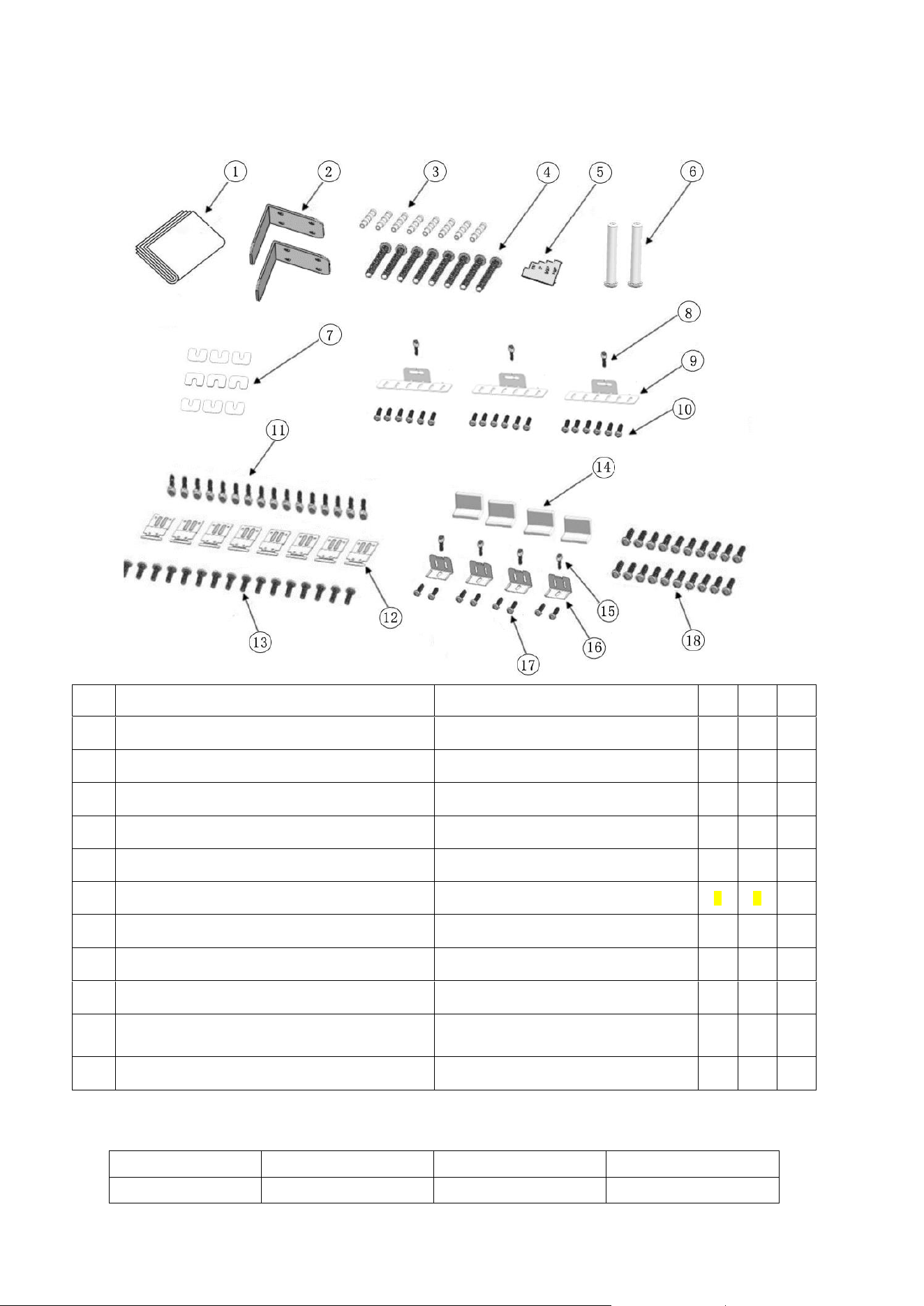
Removing mounting Parts in the Freezer
26
Compartment
⚫ Open the freezer compartment door and remove the mounting boxes and documents in the crisper.
√ Conference
No Part name spec 76 91
1
Furniture door preparation template
paper
1
1
2
Anti tip bracket
T4.0, Zn-coating
2
2
3
Dowel - 8
8
4
Anti tip bracket screws
M8*L60
8
8
5
Position adjustment jig
PS
1
1
6
90° limiting pins
sus
1 1
7
Freezer furniture door adjustment washer
abs
9
9
8 Screw freezer door hanger bracket
ST4.8*16, round head screw
3
3
9 Freezer door hanger bracket
T1.0, Cr+zn-coating
3
3
10
Screw freezer furniture door
hanger bracket
ST4x14, counter sunk head screw
18
18
11
Screw cabinet connecting bracket
M4*12, truss washer head
16
16
Category AINT7600/AINT7600IW AINT9000/AINT9000IW
Abbreviation. 76 91
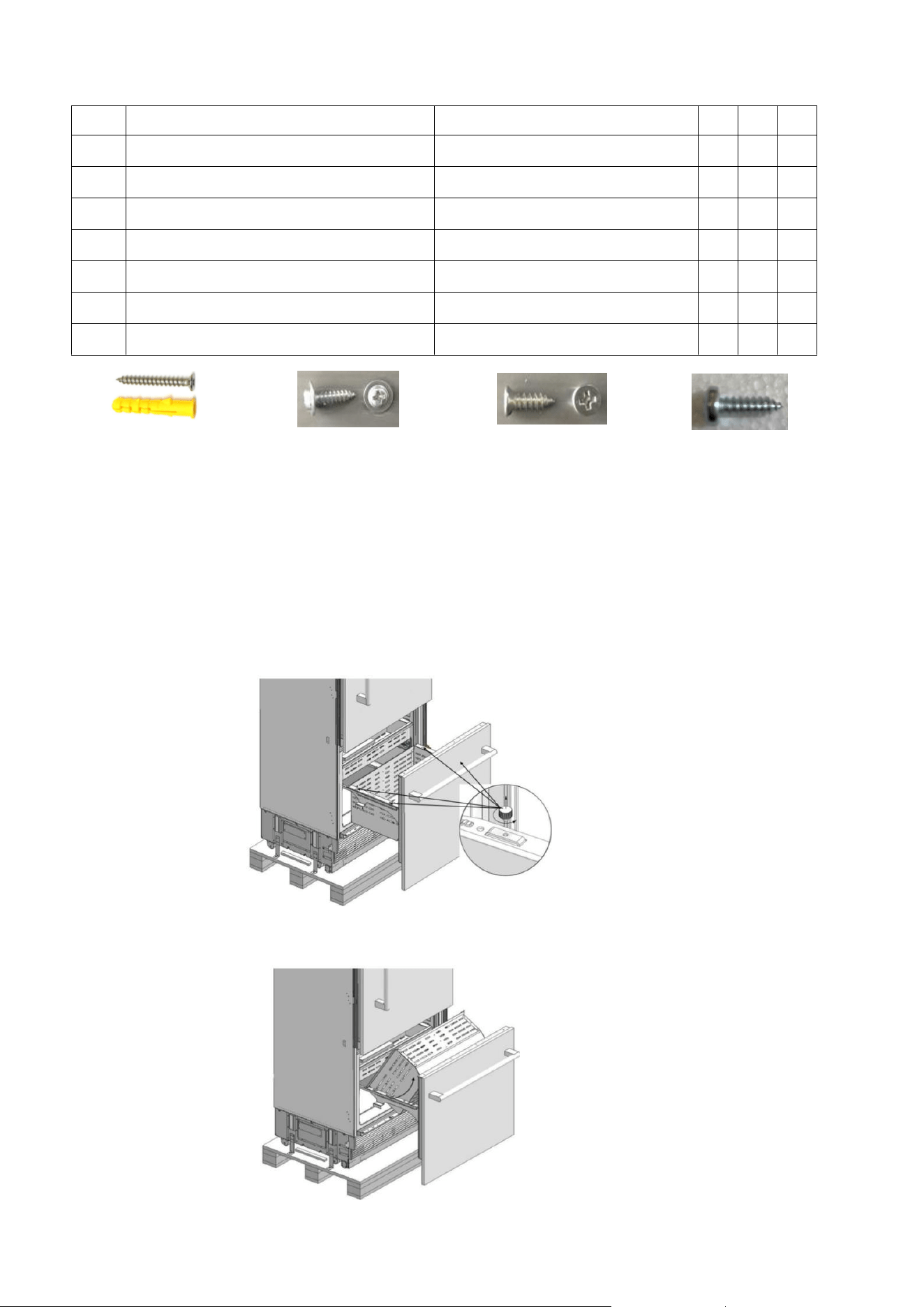
Removing the Freezing
27
Crisper
⚫ Remove it manually with 4 knurled screws.
⚫ Remove the Lower Crisper.
No Part name spec 76 91
12
Cabinet- cabin connecting bracket
T1.0, Zn-coating
8
8
13 Screw cabin connecting bracket
ST4x14, counter sunk head screw
16
16
14
Cover furniture door bracket abs 4
4
15
Screw door fixing bracket
M4*12, truss washer head 4
4
16
Door- door furniture connecting bracket T1.0, Cr+zn-coating 4
4
17 Screw furniture door fixing bracket
ST4x14, counter sunk head screw 8
8
18 Screw furniture door hanger bracket
ST4x14, counter sunk head screw
20
20
⚫ Anti tip bracket
screws
⚫ dowels
⚫ Truss washer head screw
Spec : M4x12
Fixing Refrigerator
Such as cabinet and door
(press part)
⚫ Counter sunk head screw
Spec : ST4x14
Fixing the cabin and
furniture door
(wood part)
⚫ Round head screw
Spec : ST 4.8x16
Fixing freezer door top part
and furniture door
(press part)
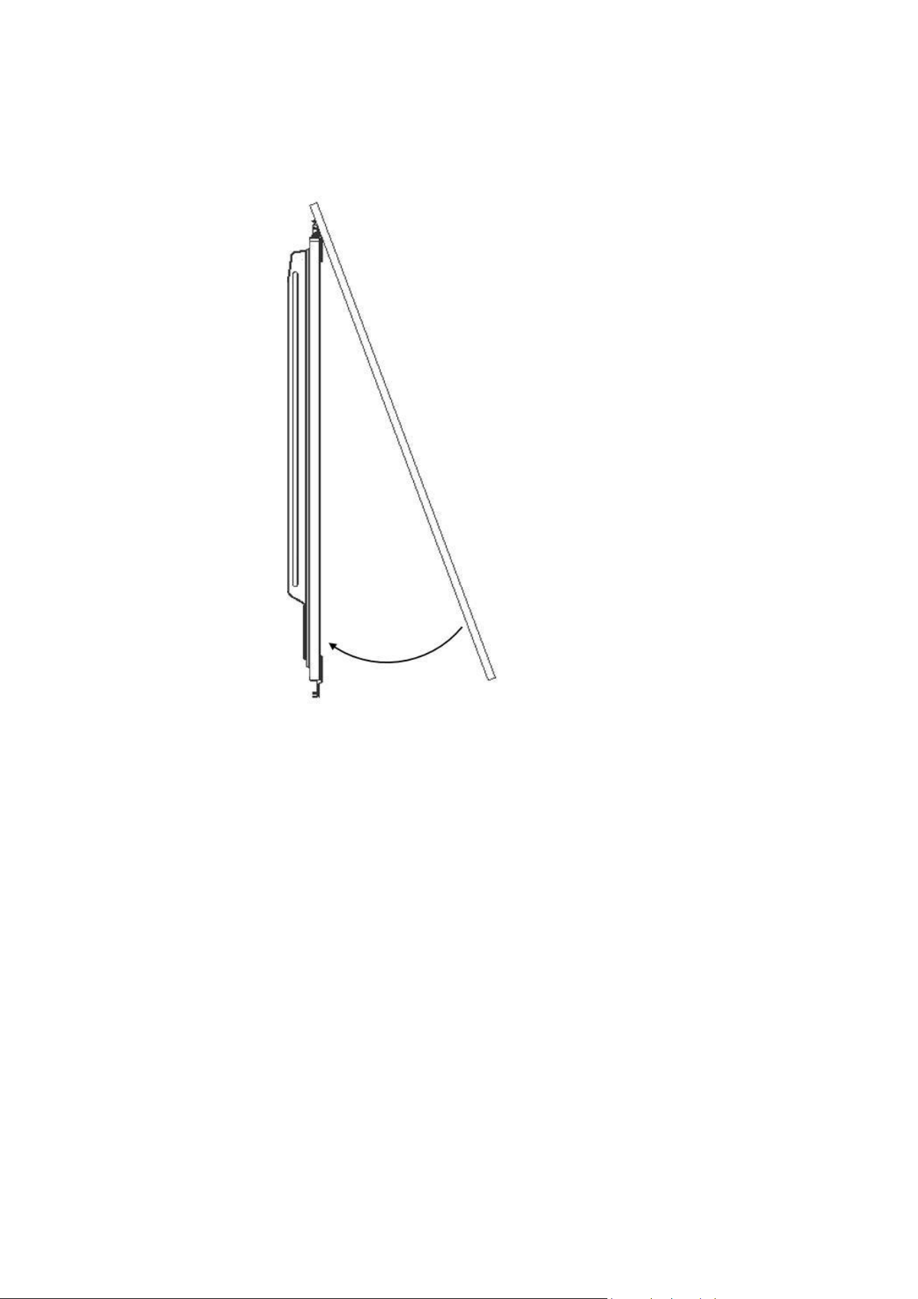
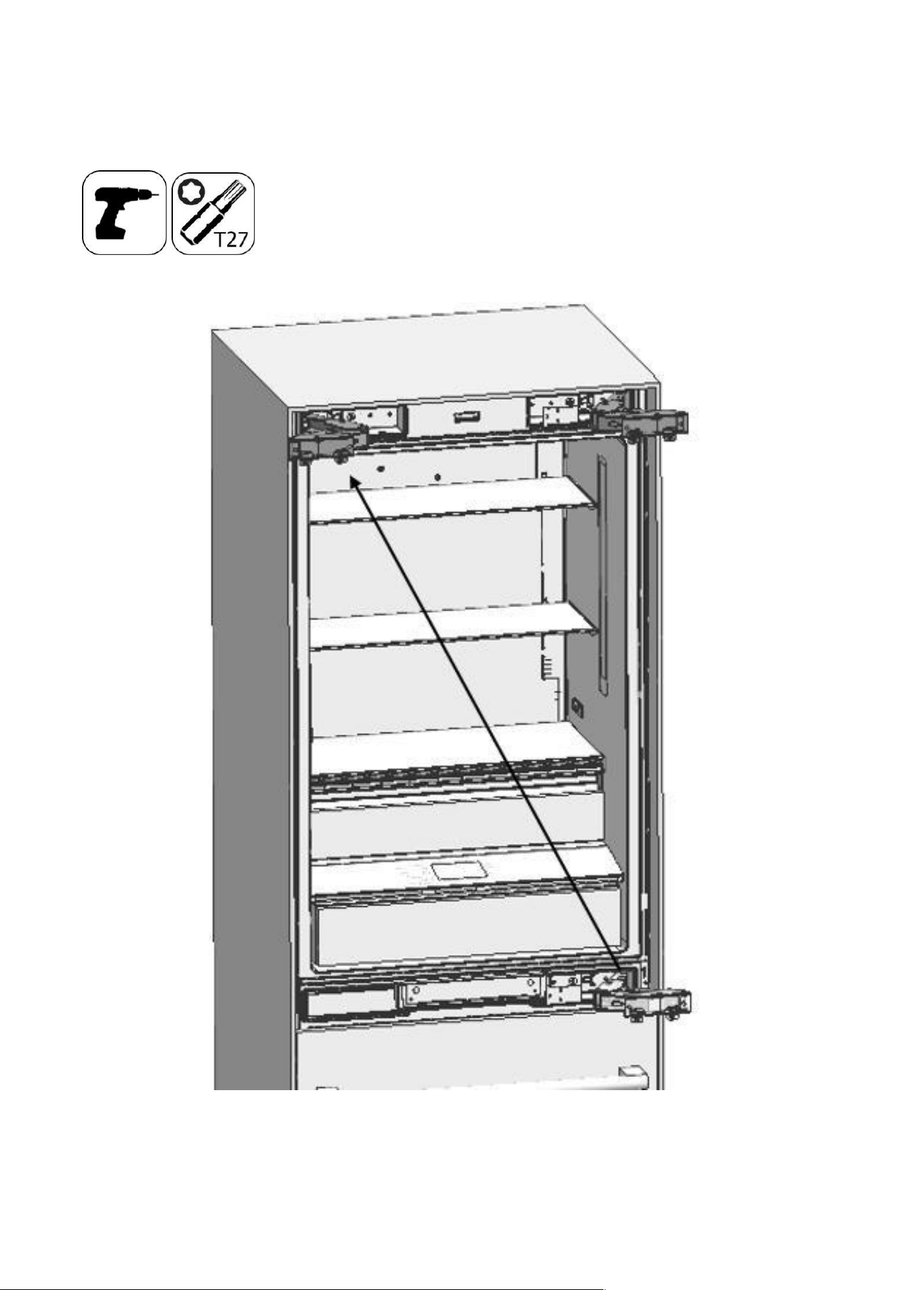
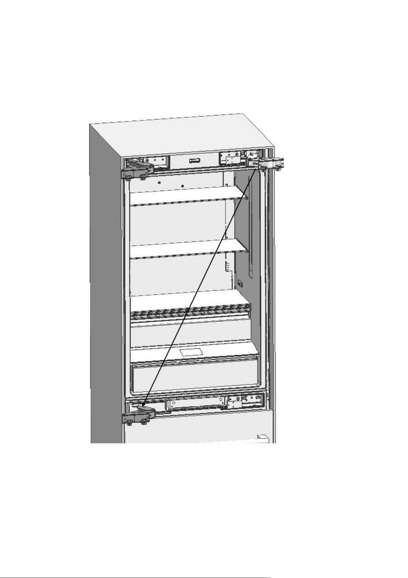
28
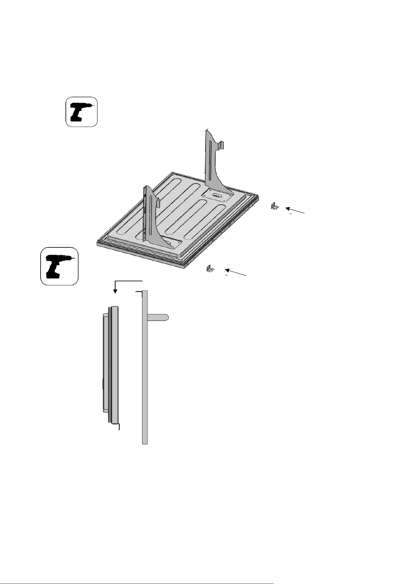
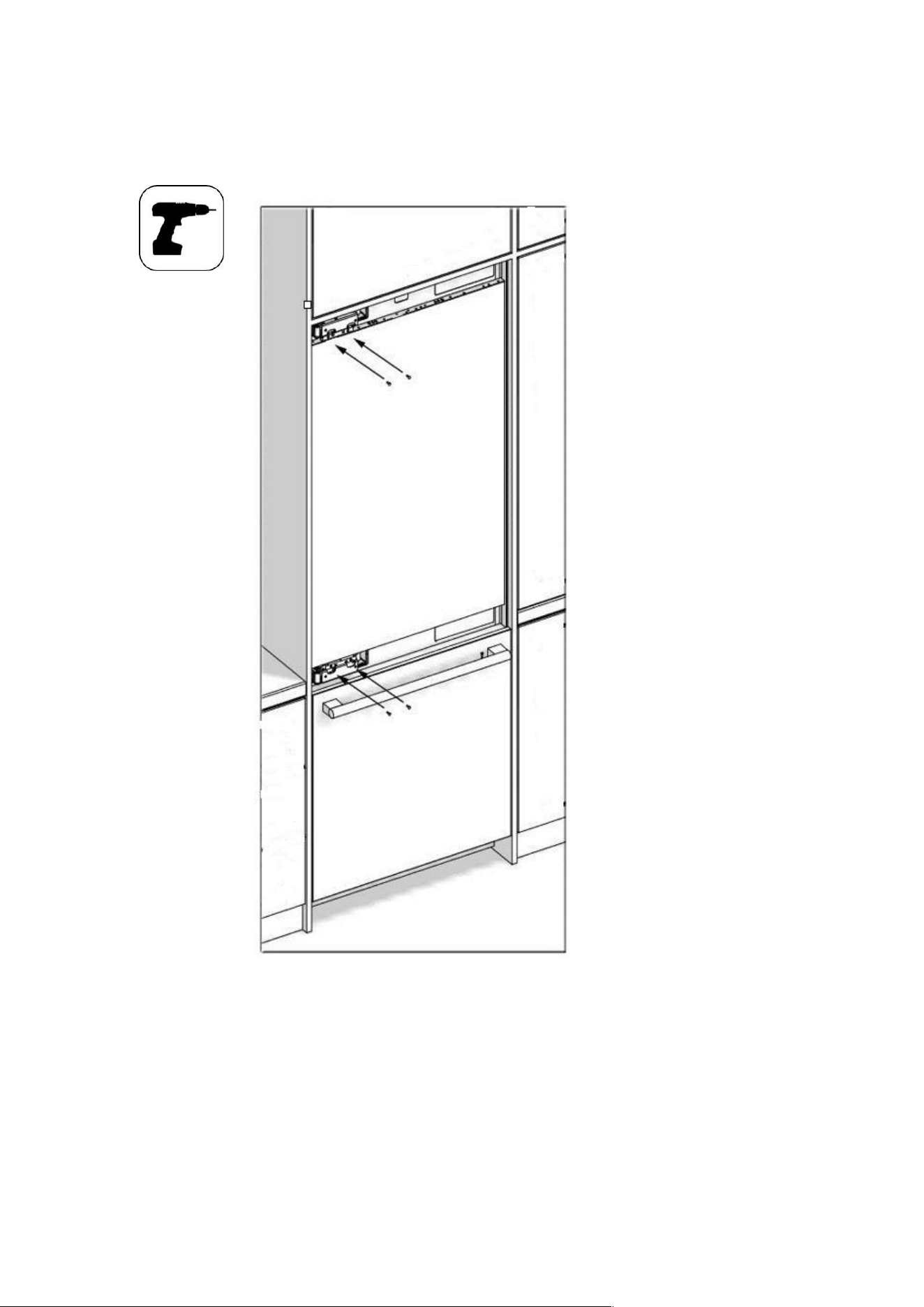
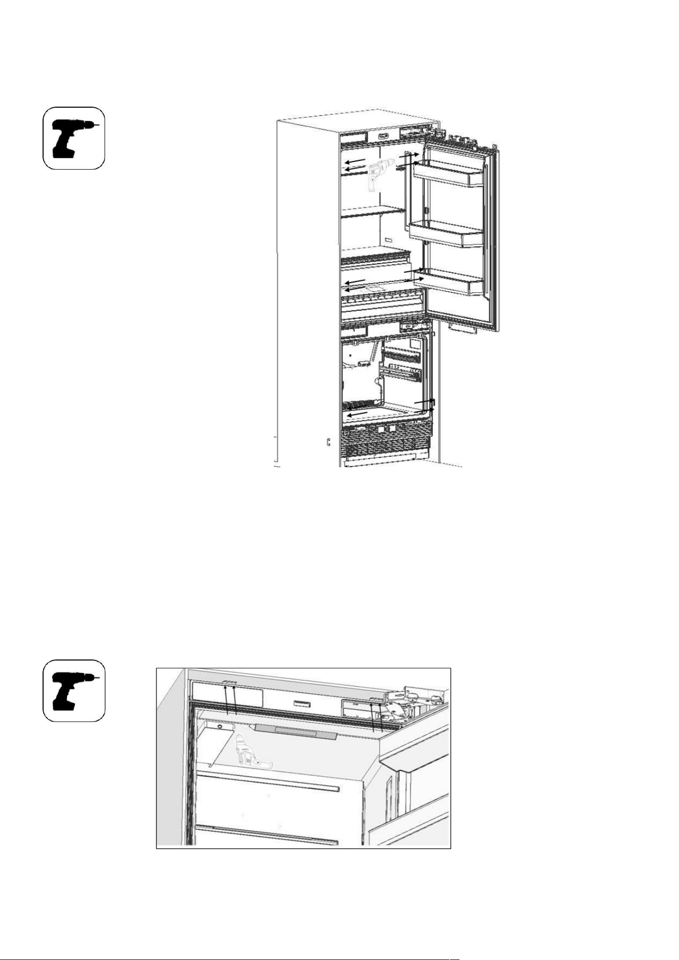
Removing the Freezing Door
Remove 2 screws which are near the front section and connect the freezing door and the rail.
⚫ Pull the door frontward to free it from the tabs at the back and remove it.
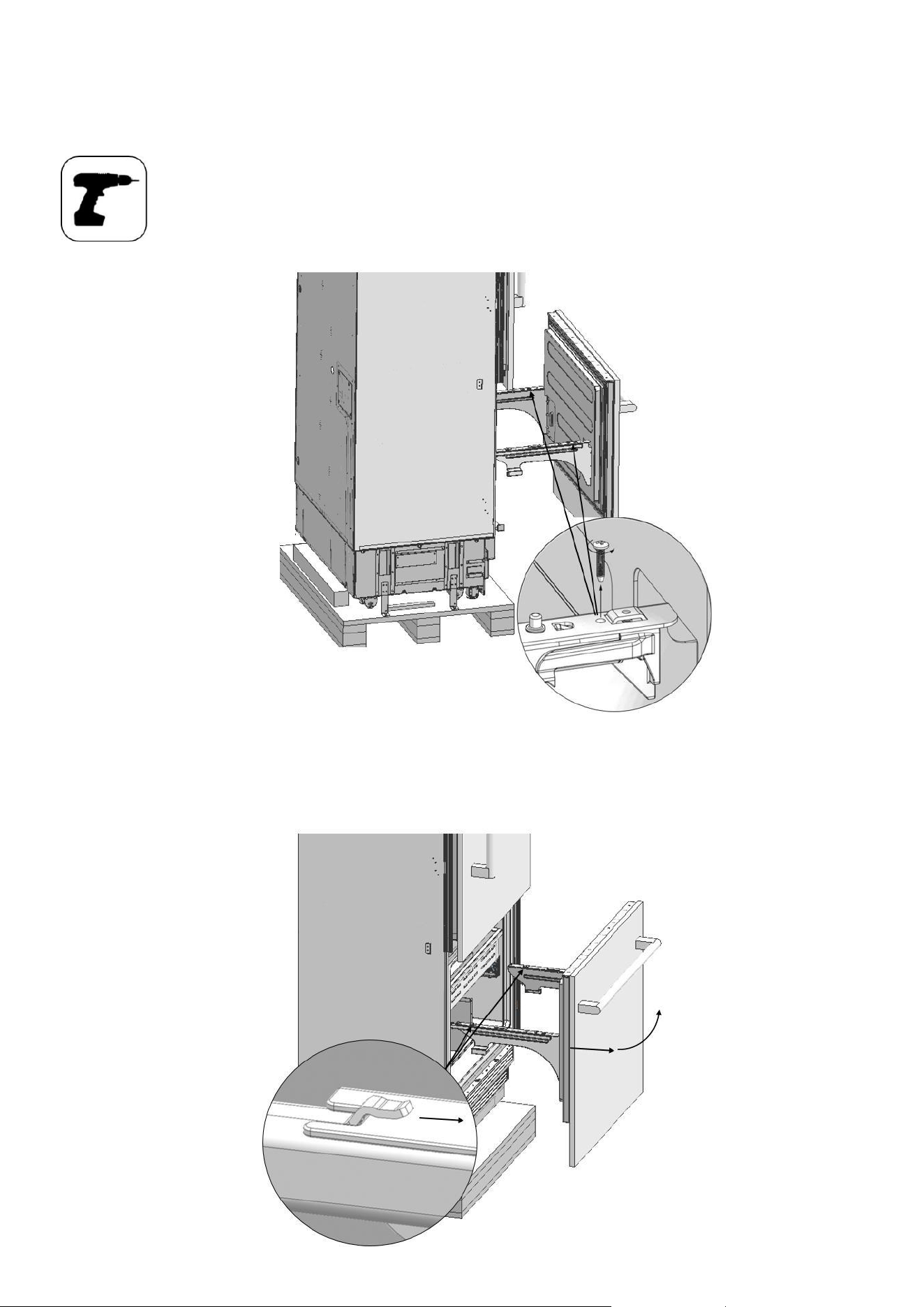
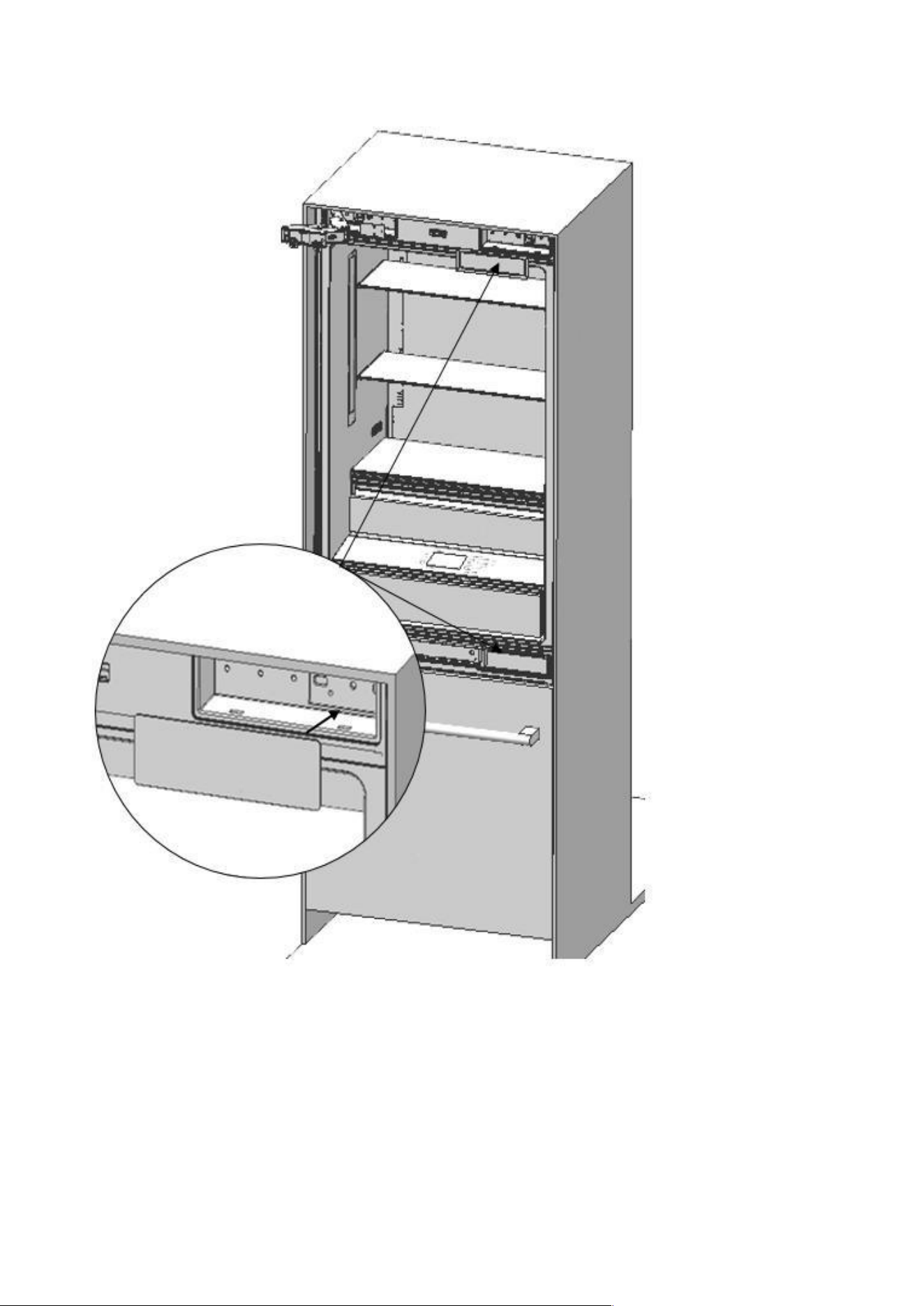
29
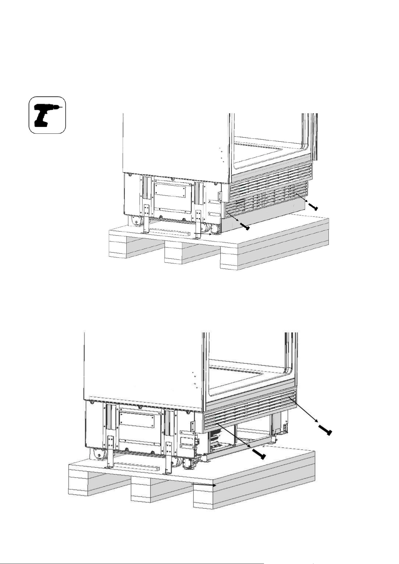
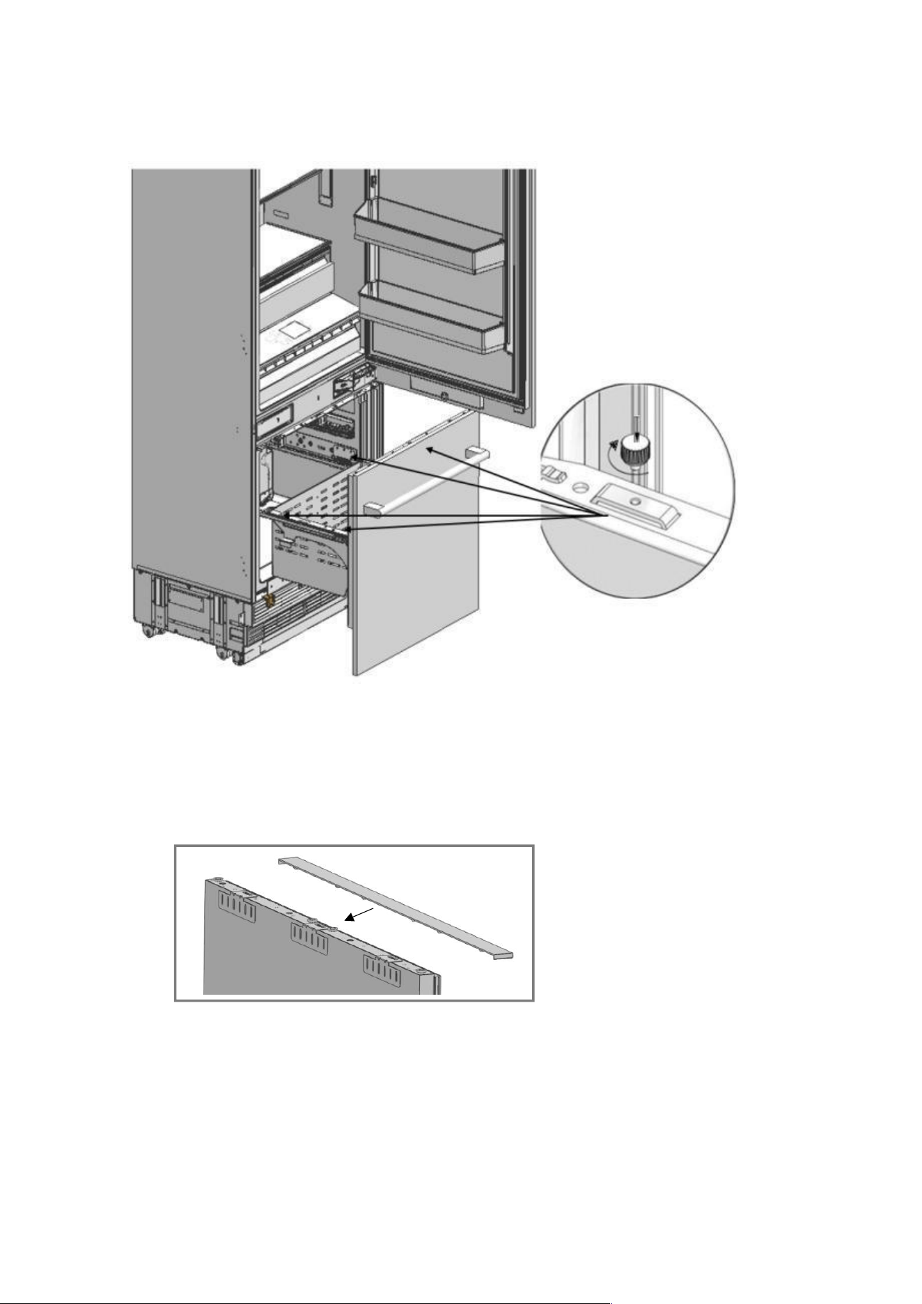
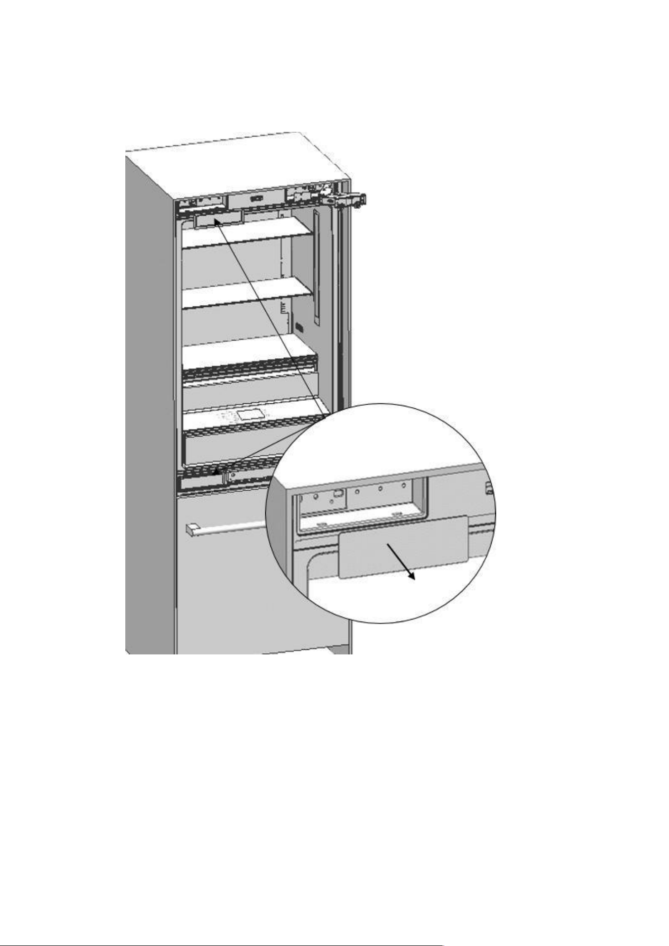
Removing the Lower Vent Hole Assembly
⚫ Remove the 2 screws to take out the Lower Vent Hole Assembly.
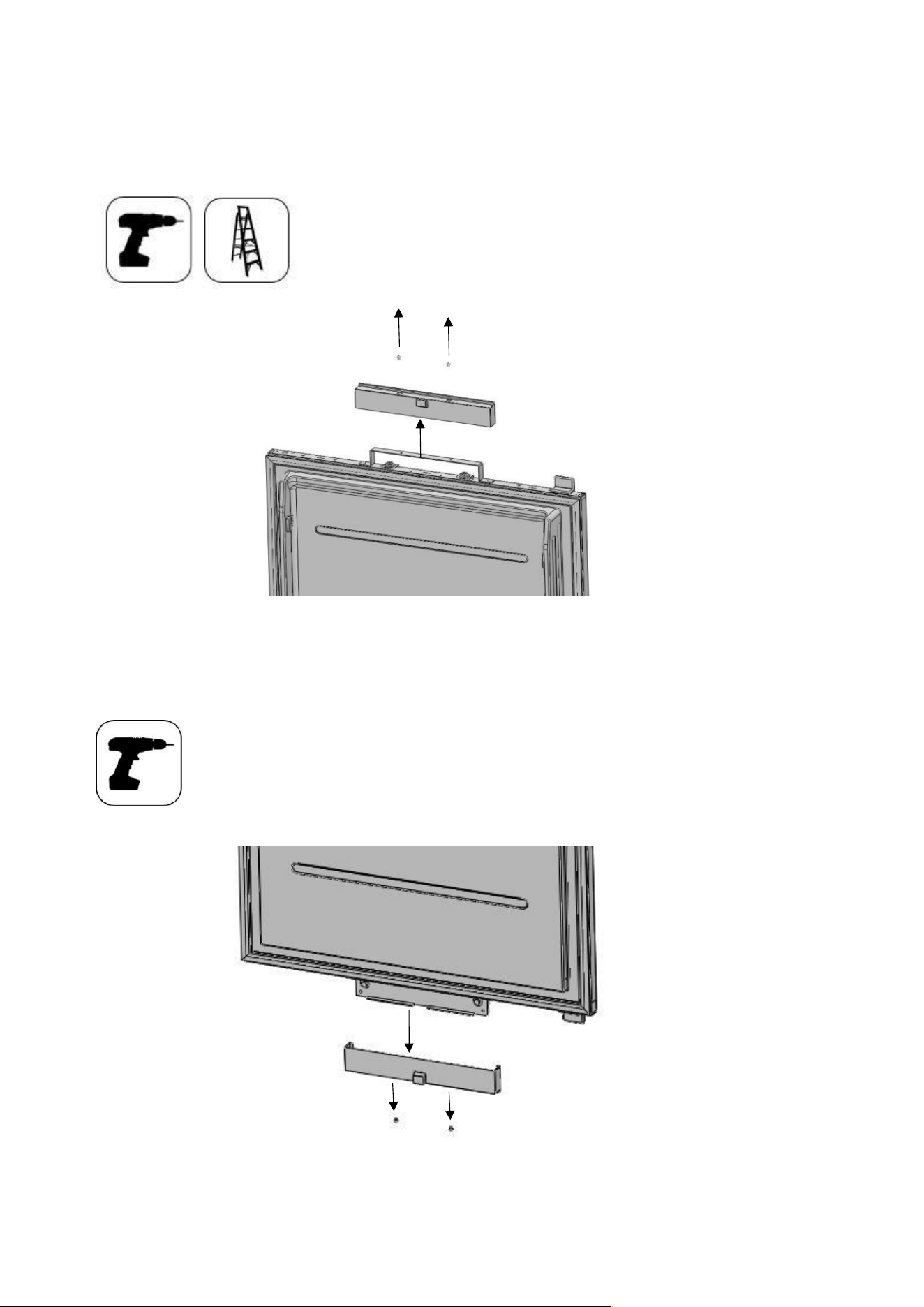
Removing the Upper Vent Hole Part
⚫ Remove the 2 screws to take out the Upper Vent Hole Part.
PRE-INSTALLATION
Continue to install the product according to the instructions below. Additionally, consider national and local
30
instructions regarding installation.
Please observe the following:
• For the USA, The National Electrical Code, ANSI/NFPA 70 – last version/State or Municipality
directives and/or regional directives.
• For Canada, The Canadian Electrical Code, C22.1 – last version/State or Municipality directives
and/or regional directives.
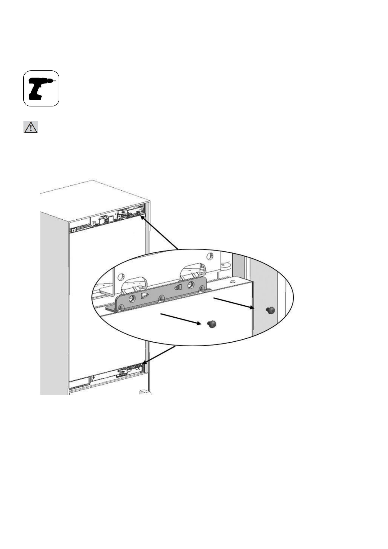
Mounting the Anti-Tip Brackets
WARNING:
You must definitely use Anti-Tip Brackets to prevent the appliance from tipping over.
WARNING:
Make sure that there is no electrical or water connection where the screws will be tightened and connections will
be established.
WARNING:
Please remember to use the necessary protective equipment when drilling holes on the wall and performing
installation.
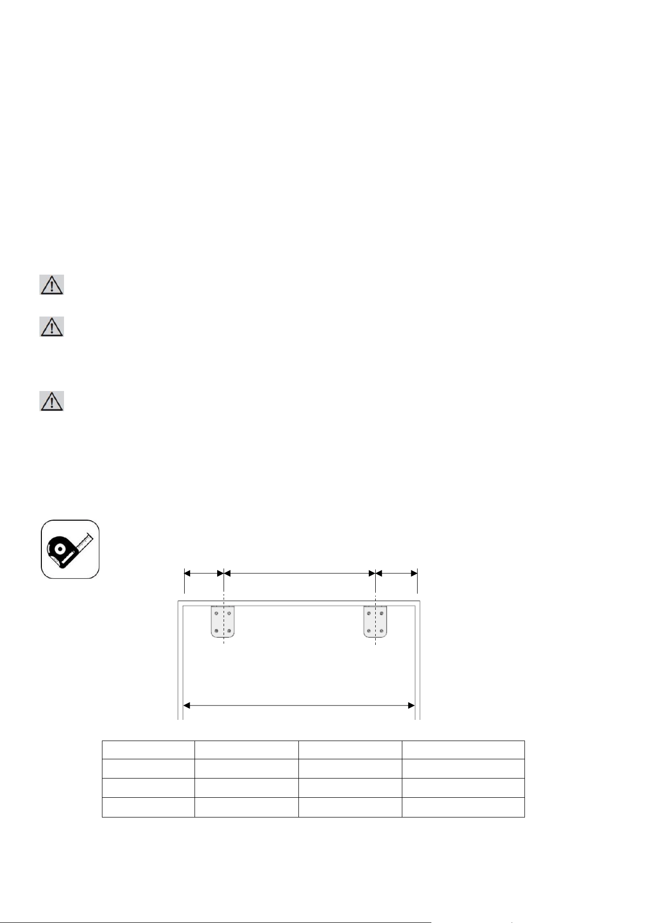
⚫ Mark the wall for Anti-Tip Brackets (item No.2).
Category
AINT7600/AINT7600IW AINT9000/AINT9000IW
A 30" (762mm) 36" (914mm)
B 23 5/8" (600mm) 23 5/8" (600mm)
C 3 3/16" (81mm) 6 3/16" (157mm)
B
C C
Anti tip brackets on the wall
A
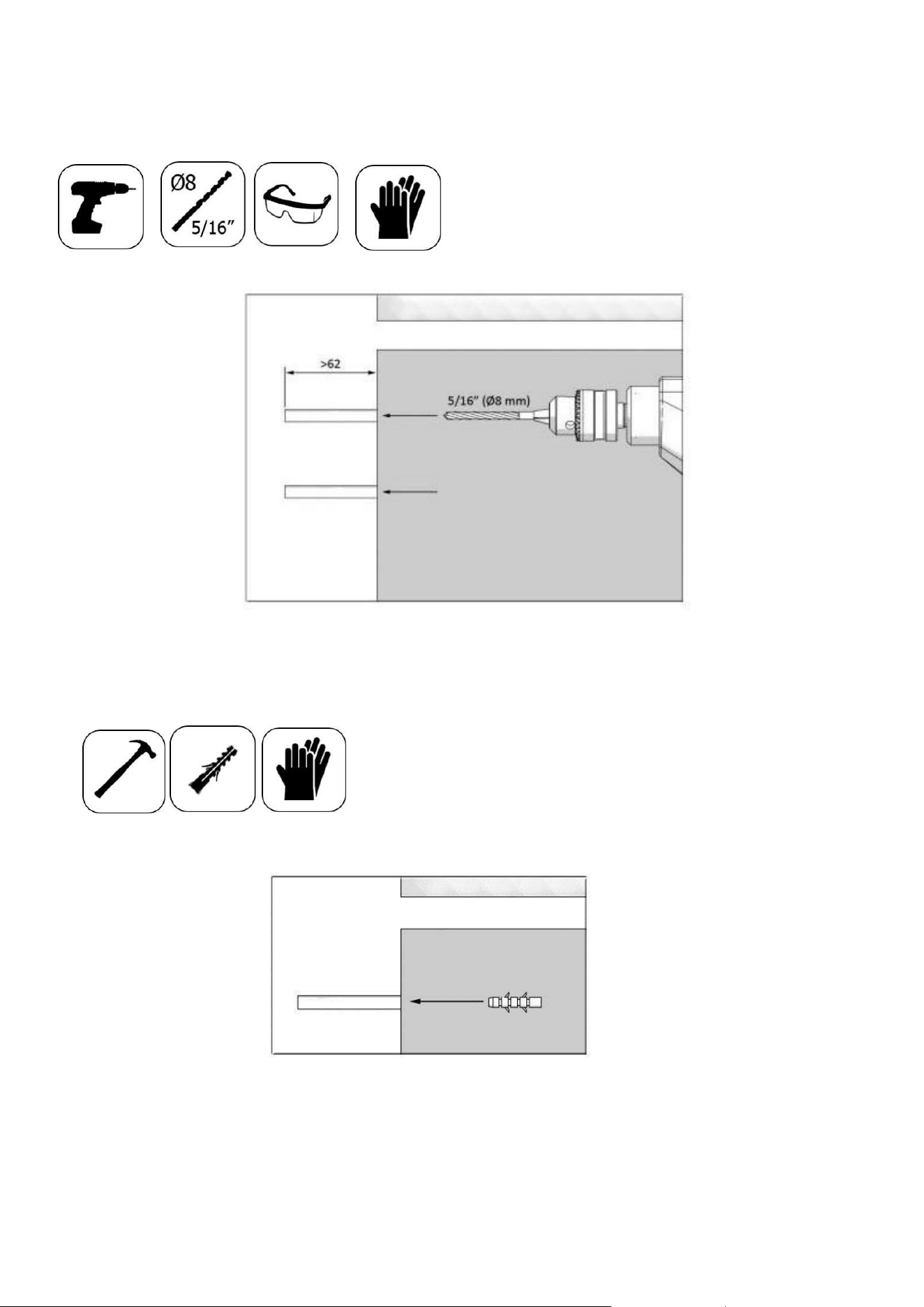
⚫ Use a drill to create holes for dowels (item No.3) at the marked points. (5/16” -Ø8)
⚫ Use the hammer to fit the dowels (
31
item No.3)
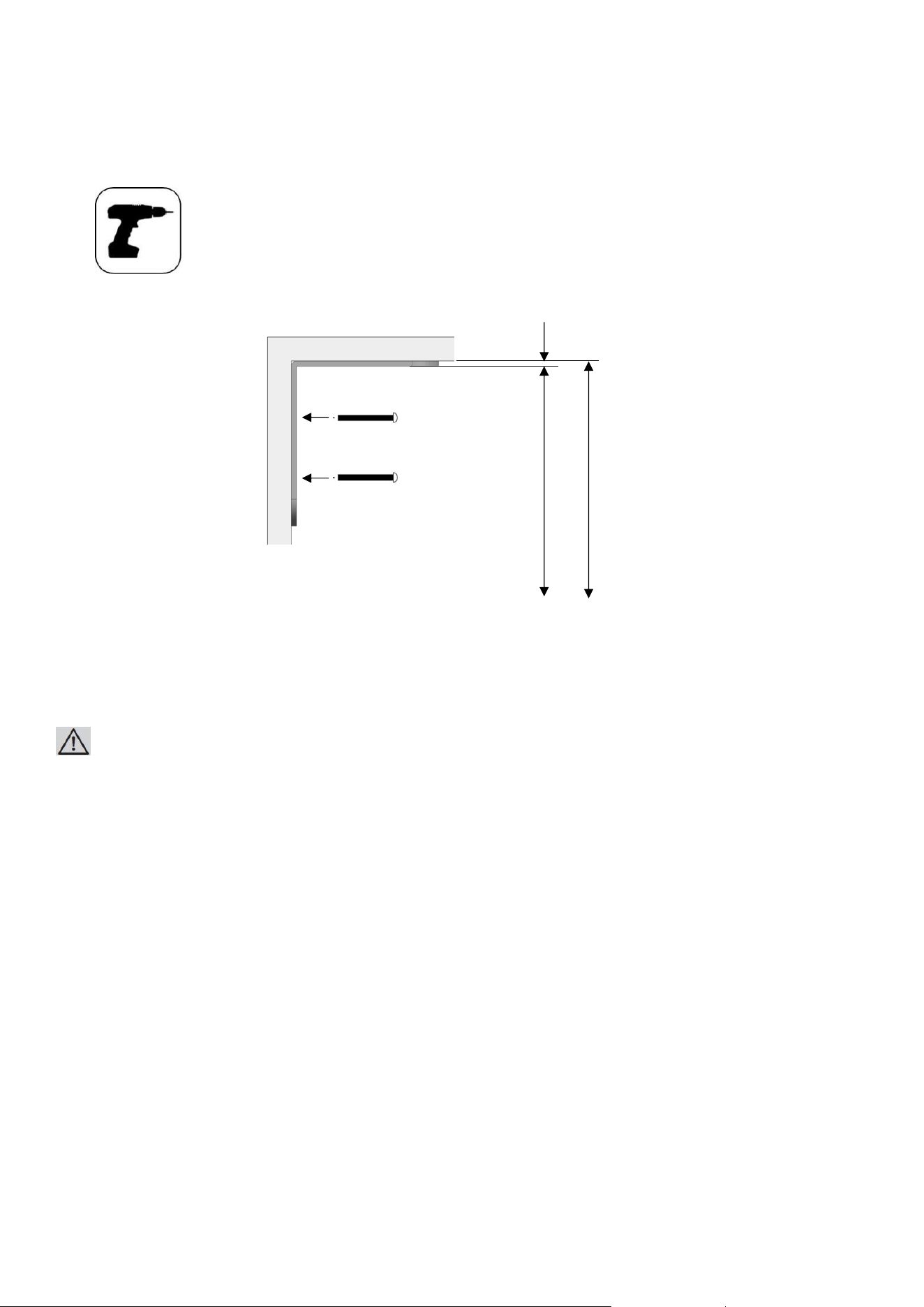
⚫ Fit the anti-tip brackets (item No.2) into their places, using 4 screws (item No.4) for
32
each.
You must use all of the 2 brackets to ensure safety of the product.
WARNING:
If you are not sure whether the existing connection parts are fit to the wall as securely as they should be,
you can use alternative anti-tip methods.
If there is furniture at the back wall of the refrigerator, please make sure that the furniture is fixed to the wall.
For this, you need to be sure that the back wall of the furniture is fixed to the concrete back wall
with suitable connection parts.
5/32” (4mm)
84” (2134mm)
83 27/32” (2130mm)
Thickness
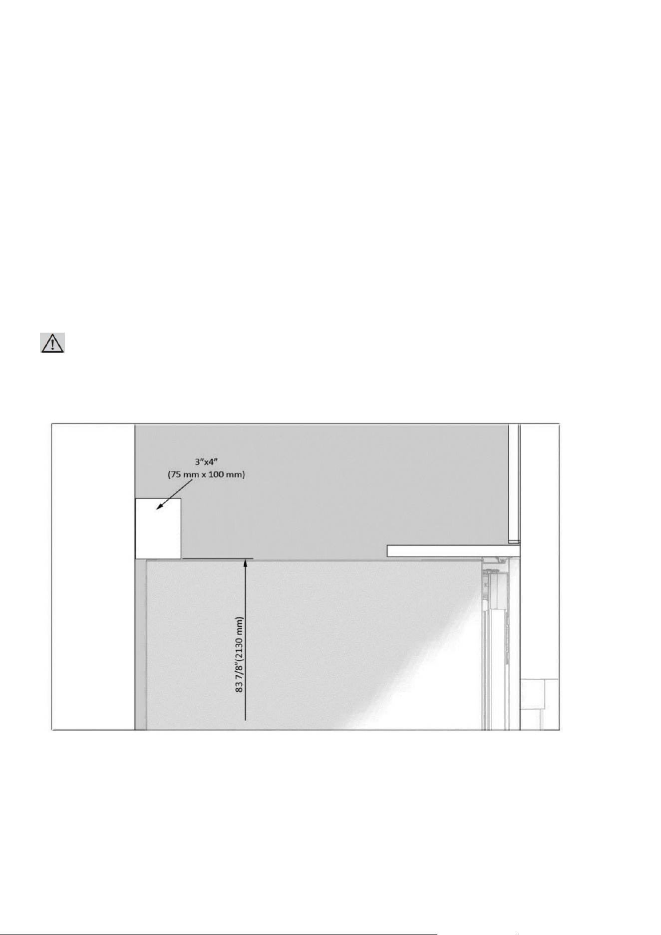
Alternative anti-tip method:
If the anti-tip brackets cannot be connected securely, you must use the alternative method below.
In this method, you can use wooden girders to avoid the risk of tipping over.
It must be installed as illustrated in the figure below.
There must be no clearance between the product and the wooden girder.
Minimum section dimensions of the wooden girder must be 3"x4" (75 mm x 100 mm). Width of the girder must be
equal to the clearance where it will be installed.
An additional girder must be used if the niche depth is more than anticipated. The wooden girder must contact the
product with a maximum size of 2" (50.8 mm).
33
To determine the location for the wooden girder, mark it on the rear wall, select suitable screws and connect safely.
WARNING:
Number and features of the screws to be used for the wooden girder must be determined so that there is no safe
connection.
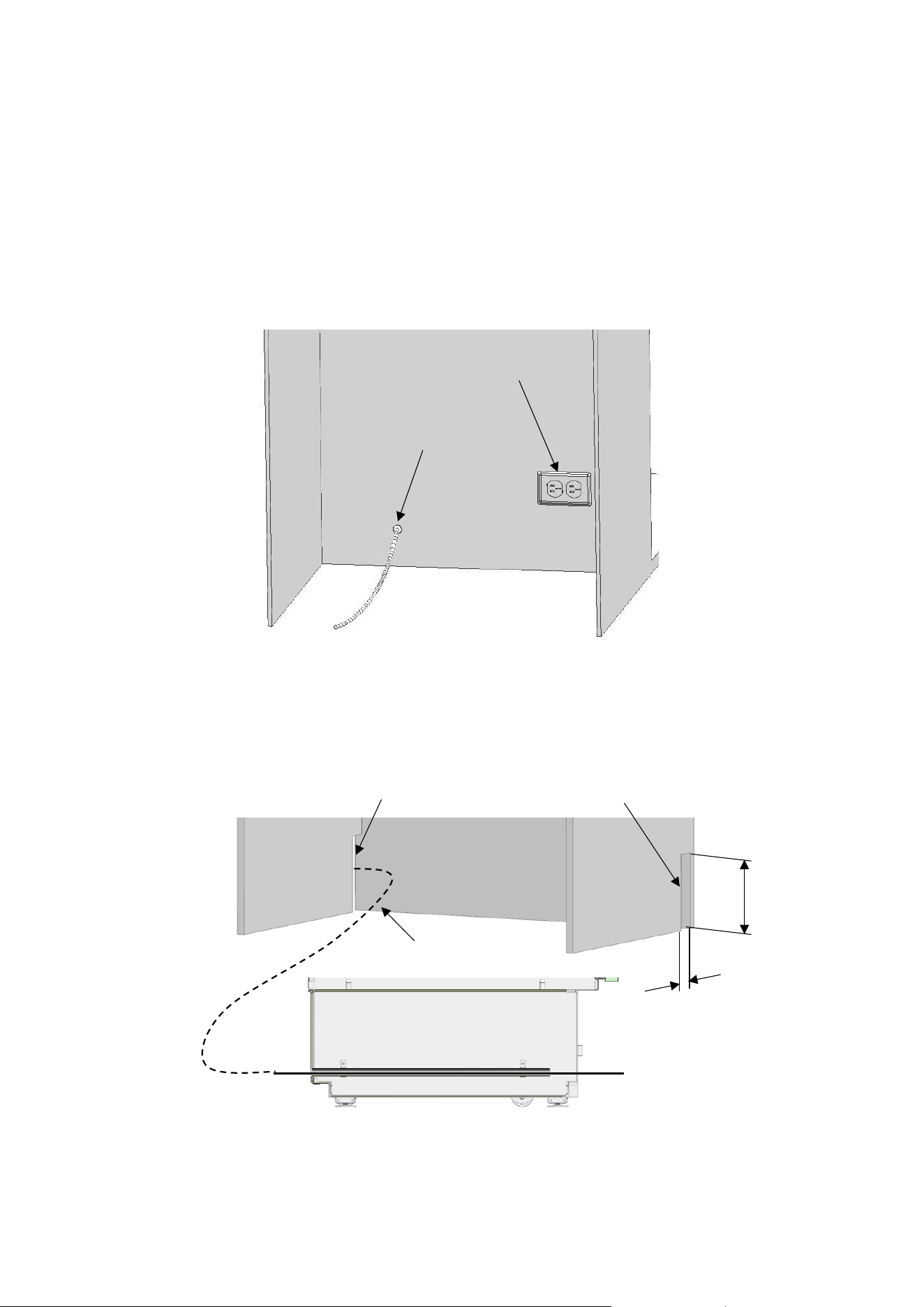
Preparing the Water Hose and the Power Plug
You will need a hose with a minimum length of 60" (1.5 meters) and a diameter of ¼" water connection
of the product during installation.
A connector that has a thread with an external diameter of ¼ must be used to connect the hose end to the product.
You
34
can choose the method A or method B below to prevent the cable from getting jammed.
⚫ Method A :Locate the water hose and power supply on the back
⚫ Method B :Locate the water hose and power supply on the side
Water hose
2” (50.8mm)
8” (203.2mm)
Keep for Power cord
Keep open for water line
water line location
Cable location
INSTALLATION TO THE CABIN
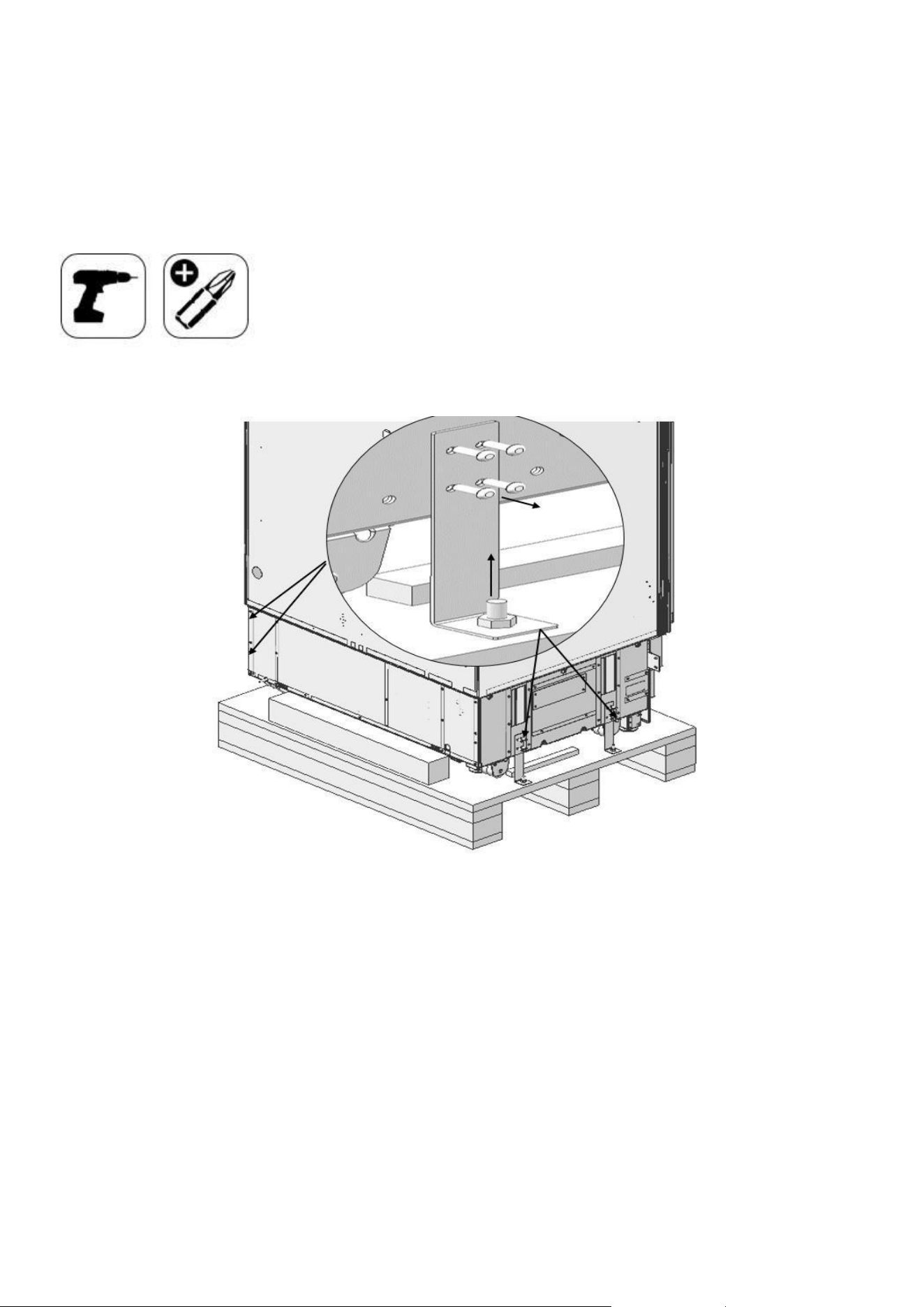
Taking the Refrigerator from the
35
Wooden Pallet
⚫ Remove the brackets that connect the refrigerator to the Wooden Pallet.
⚫ Recline the refrigerator slowly and pull back with the help of the cart, and then land
36
it.
ATTENTION:
The risk of tipping over is high as of this point. You should not open the doors
until the product is placed into the cabin.
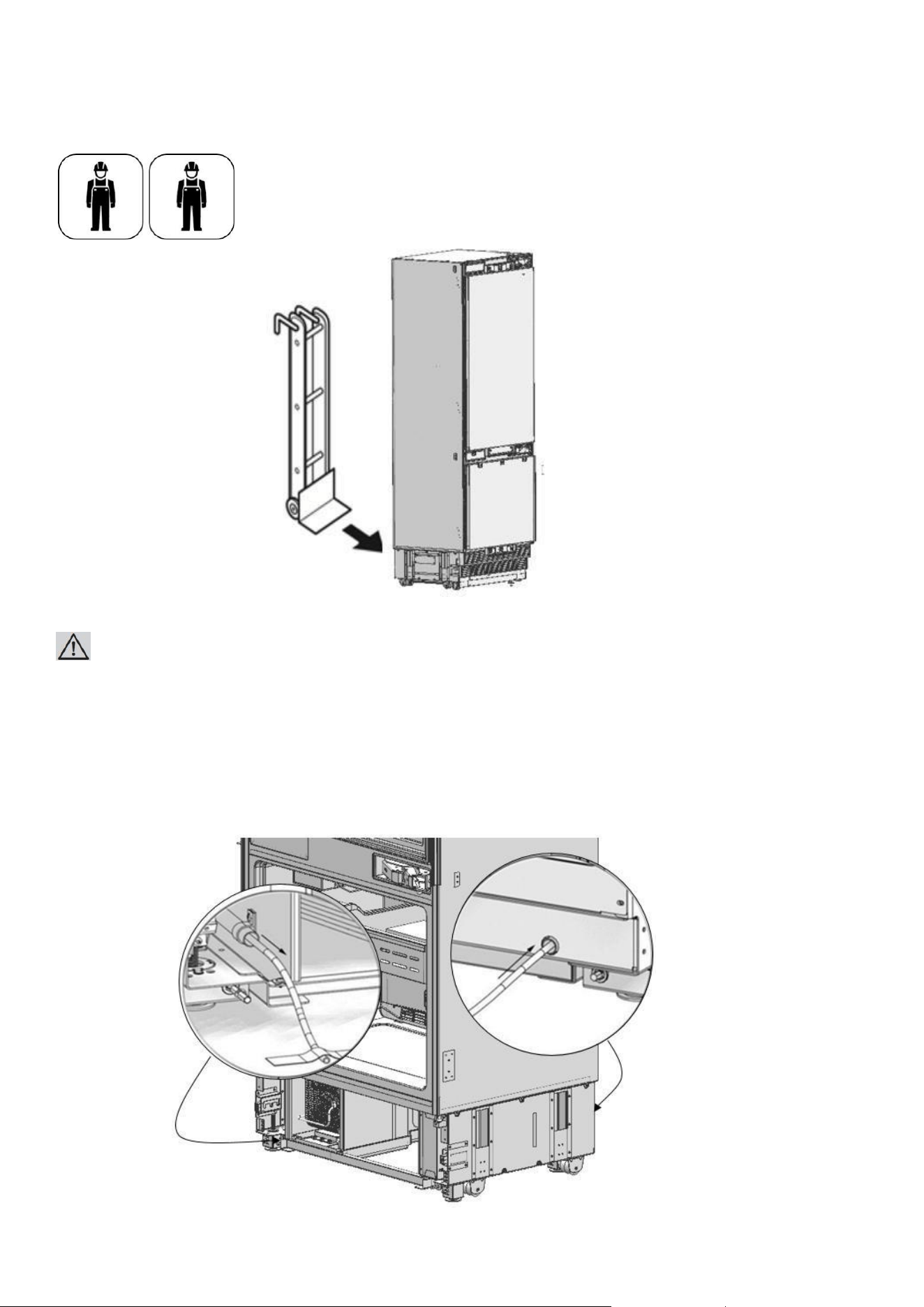
Placing the refrigerator into the cabin
⚫ Insert the mains water hose into the duct at the back and take it out from the front.
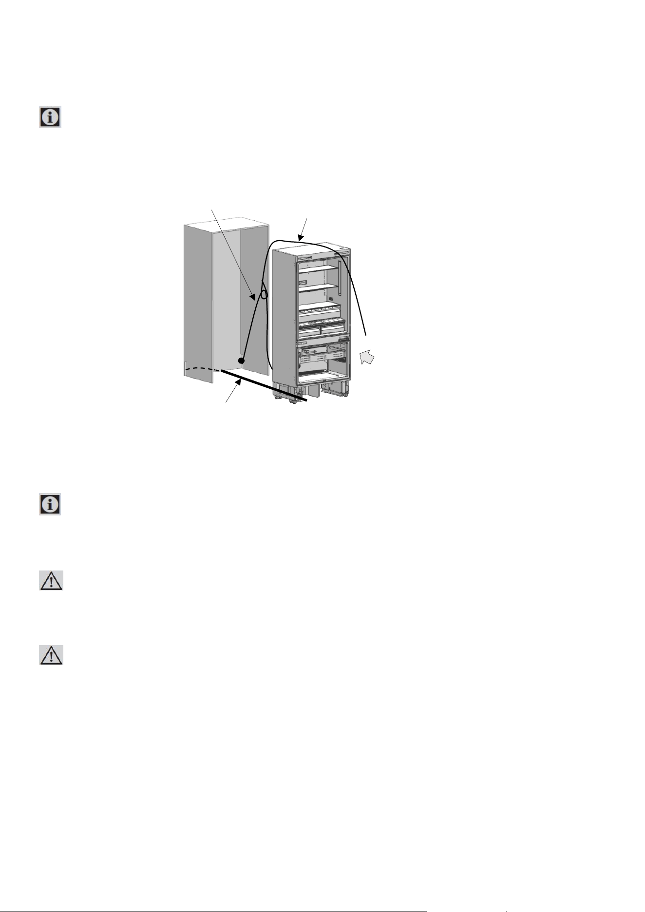
IMPORTANT
37
INFORMATION:
⚫ Apply the below method to prevent the cable from getting jammed.
⚫ Start the refrigerator and make sure it is energised. (You can check if the lamps of the freezer
compartment are on or off to see if the product is operating).
IMPORTANT INFORMATION:
You can use tape and similar protectors on parts you think this is necessary to protect the edges of the furniture
when placing the product.
WARNING:
The plug of the product must be accessible after installation. If the plug is not accessible after installation, the power
must be cut off from the main switch.
WARNING:
Make sure that the mains cable is not jammed when placing the product.
⚫ Push the product carefully towards the cabin to place it. If there is strain during the placement
of the product into the cabin:
- The floor might be rough or uneven.
- Adjustable feet might be loose.
(please see the relevant section to learn how to adjust the adjustable feet)
⚫ You must attach the Freezer Door temporarily to align the product before placing it.
You must use the upper edges of the Freezer Door when aligning the product with the furniture.
Adjustment of other edges are explained in the following pages.
Nylon string
Power cord
Water hose
Move to walll
38
IMPORTANT INFORMATION:
You must use the upper edges of the Freezer Door when aligning the product with the furniture.
Adjustment of other edges are explained in the following pages.
39
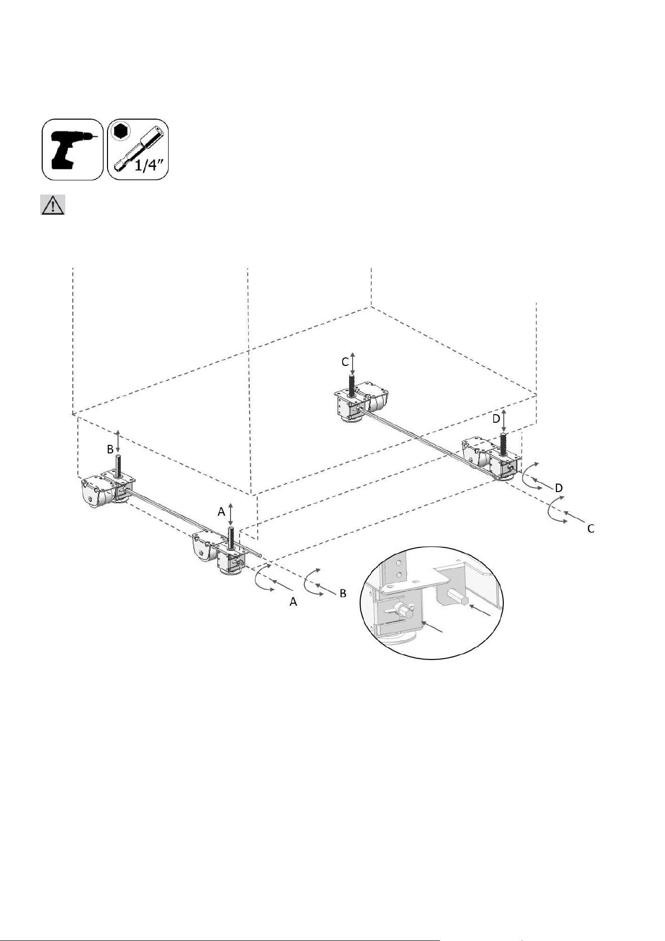
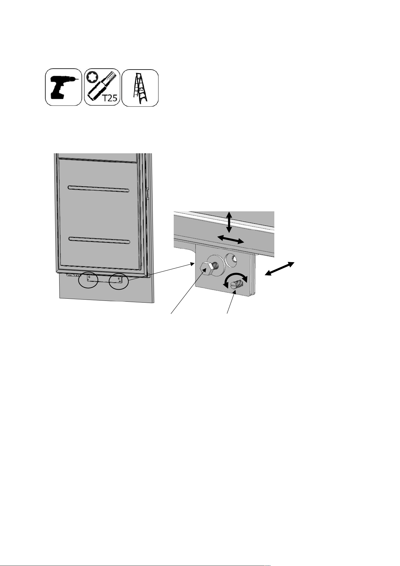
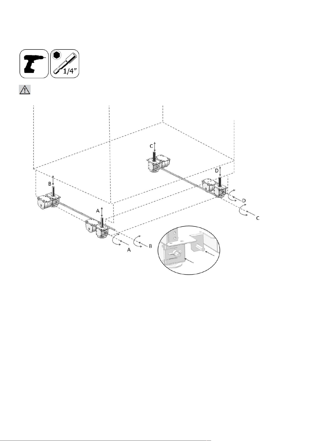
Adjusting the height of the refrigerator in the cabin
⚫ Adjust the refrigerator height using the adjustable feet.
WARNING:
First of all, raise the front feet to reduce the risk of the cabin falling frontward.
A/D –Turn the key clockwise to lift the front
B/C –Turn the key clockwise to lift the rear.
⚫ After adjusting the adjustable feet, check the flatness in both width and depth
40
directions.
The maximum height that the adjustable feet can reach is 1 9/16" (40 mm) and the product height is 85 3/8"
(2,169 mm)
IMPORTANT INFORMATION:
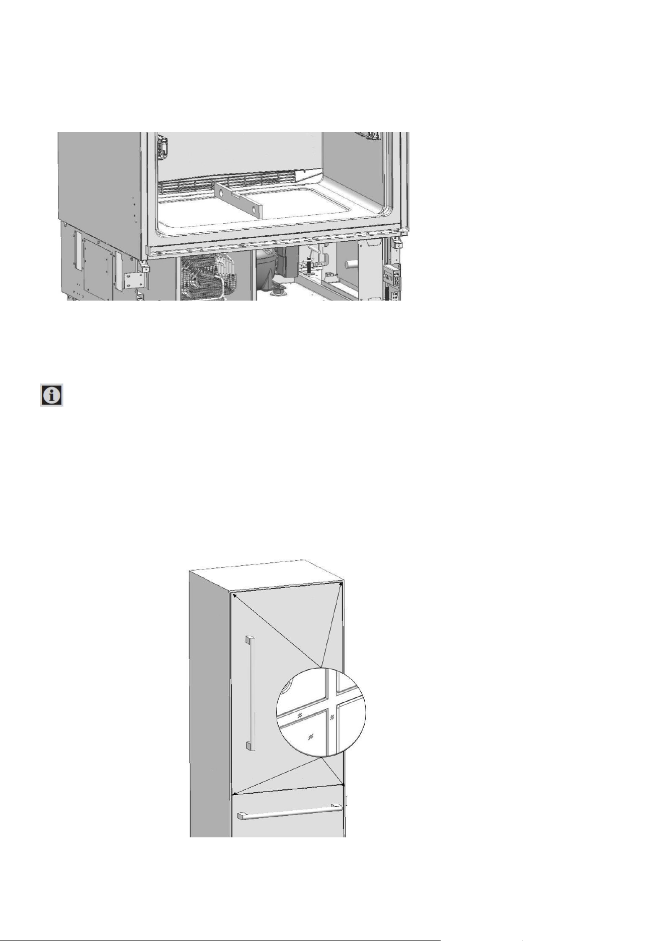
Adjusting the refrigerator according to the cabin flange
⚫ For products with clad doors, the position of the Refrigerator is adjusted
so that the door and the furniture surface are flush.
You can also use position adjustment jig (Item No5) if necessary.
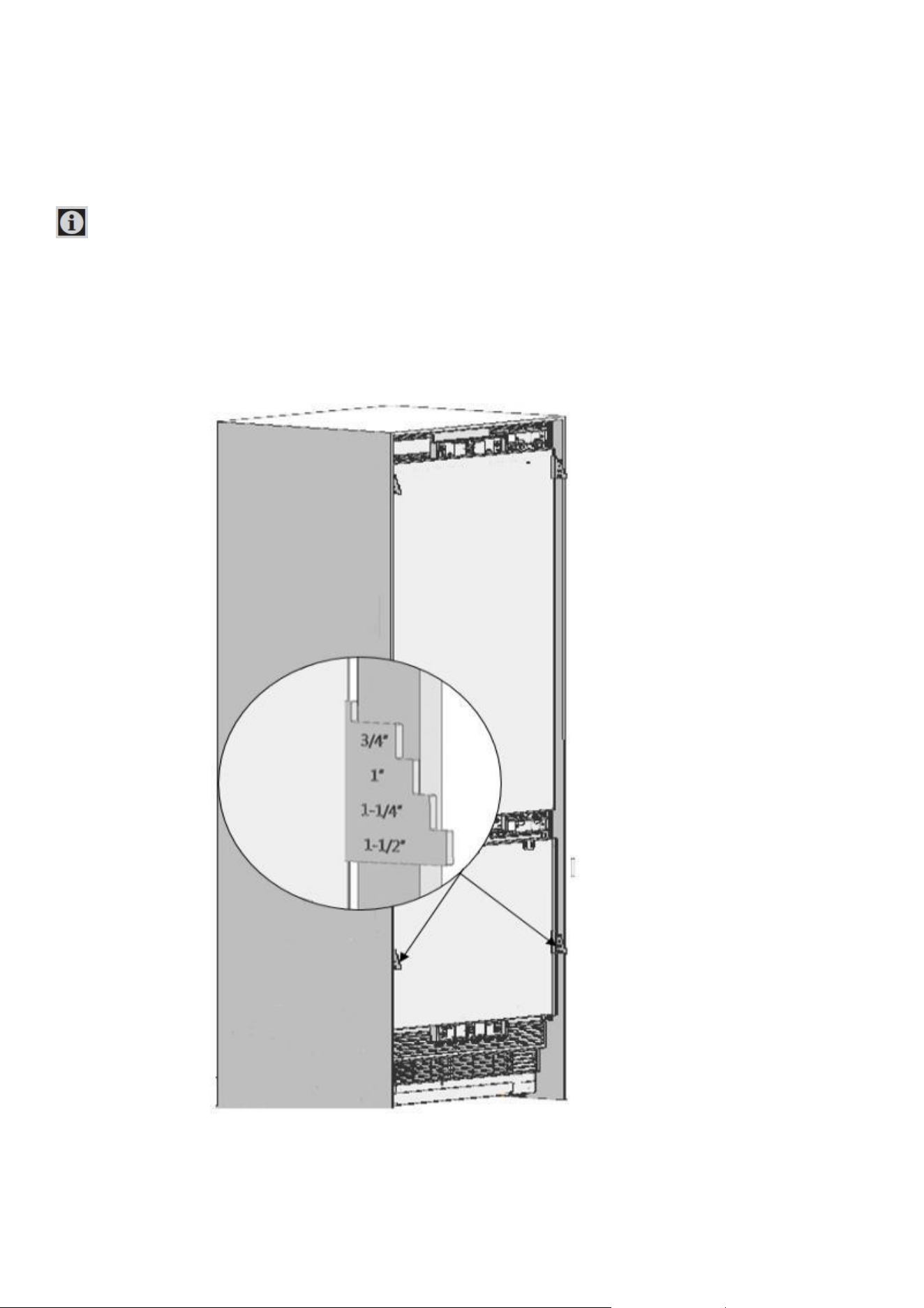
⚫ For products without furniture doors, the product is placed using the Adjustment part (Item
41
No5)
as shown in the figure below.
IMPORTANT INFORMATION:
It is very important to align the upper edge of the Freezer door when aligning.
All the other edges can be adjusted with the adjustment mechanisms.
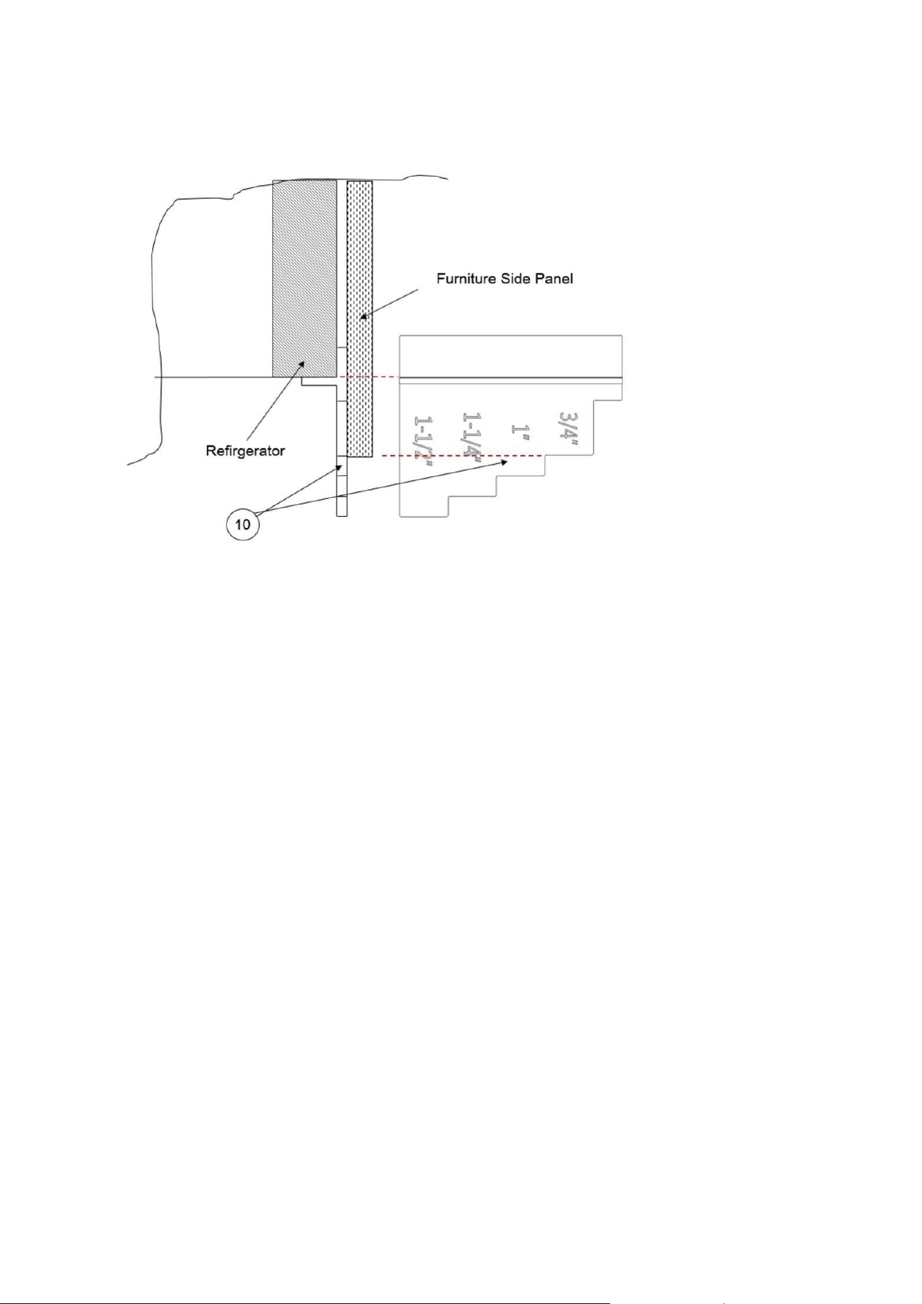
⚫ The position adjustment jig (Item No5) must be adjusted according to the thickness
42
of the door.
It can adjust the level for 4 different door thickness levels.
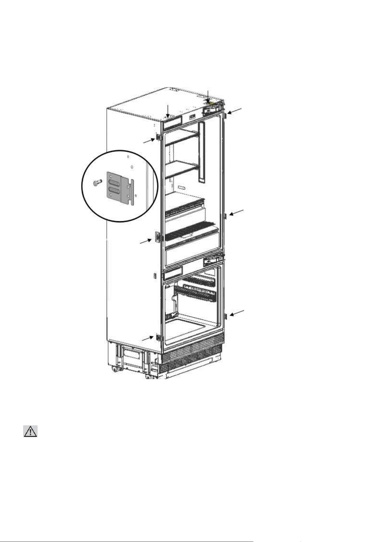
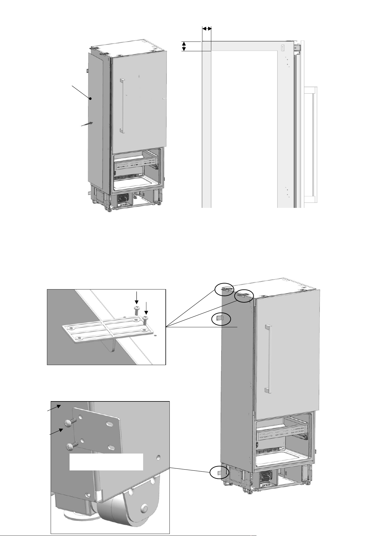
Screwing the cabinet-
43
cabin connecting bracket
⚫ Fix the cabinet-cabin connecting bracket (Item No12) to the cabinet, where 2 on the top, and 3 on every side.
Use screw cabinet connecting bracket (Item No11) to tighten.
WARNING:
Before starting to screw the Side and Upper brackets, please make sure that water is supplied to the product and
there is no water leakage.
44
IMPORTANT INFORMATION:
If you have difficulty tightening the screws, opening a reference hole with the drill will make this procedure easier.
⚫ Attach cabinet-cabin connecting bracket (Item No12) to the cabin.
with 16 screws cabin connecting bracket (Item No13).
INSTALLING THE CABIN BOTTOM
45
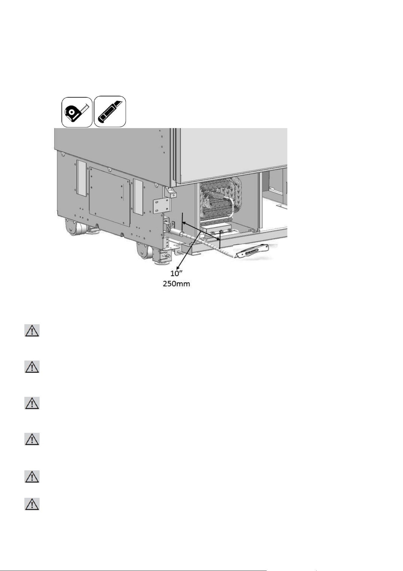
Water connection
⚫ Use the box cutter to cut the water hose from the end of the pipe it comes out,
leaving a section of 10".
⚫ Use the 2 wrenches to firmly connect the hose coming from the mains and the hose coming
from the valve.
WARNING:
The hose coming from the mains must be one piece. Do not use extension hoses.
WARNING:
Make sure that the power is cut off when making the water connection of the product.
WARNING:
The water valve must be off when connecting the water hose.
WARNING:
It is recommended that the water on/off valve remains accessible after installing the product.
WARNING:
This product is suitable for use with cold water mains only.
WARNING:
Pressure of the water system must be between 25-80 psi (1.7-5.5 Bar).
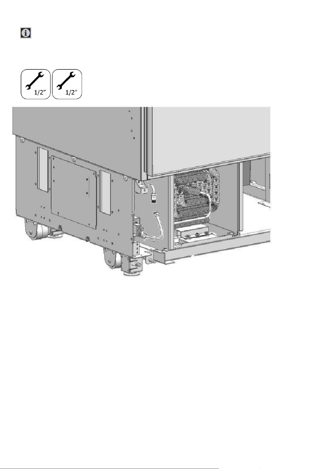
IMPORTANT
46
INFORMATION:
Once the connection is complete, you must turn on the mains valve and make sure
that there is no leakage at that point.
47
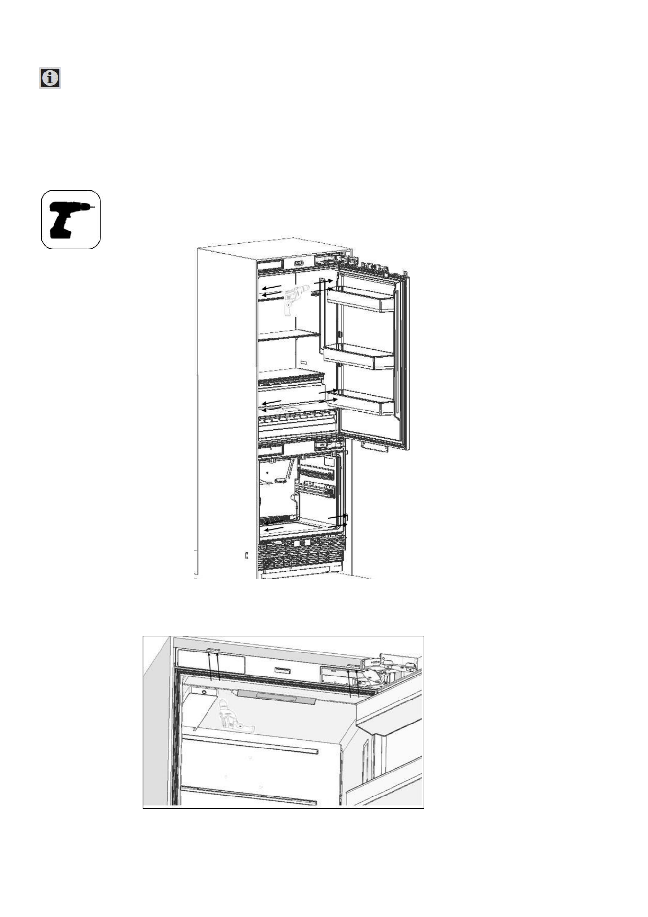
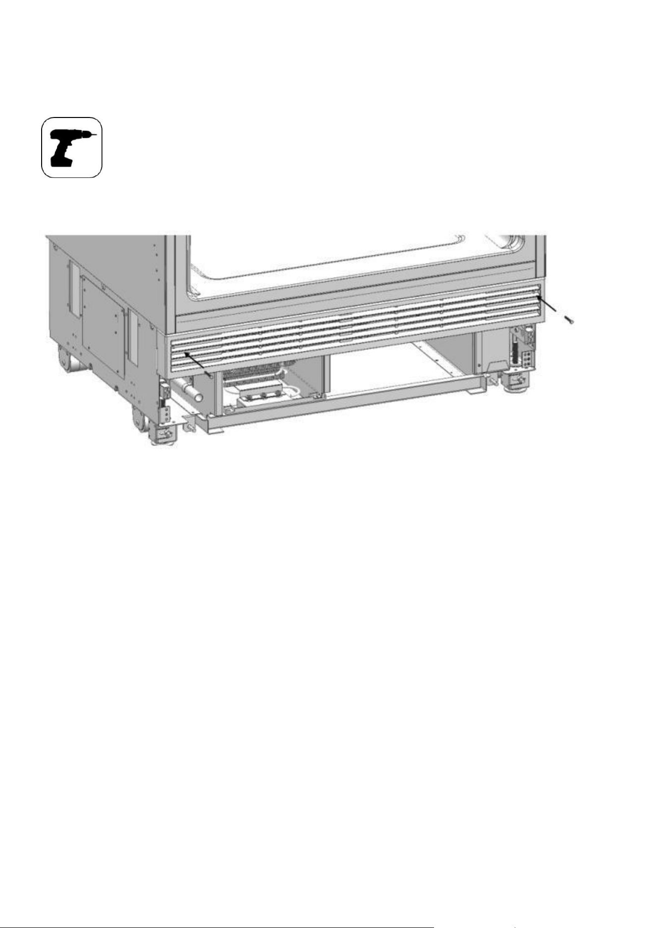
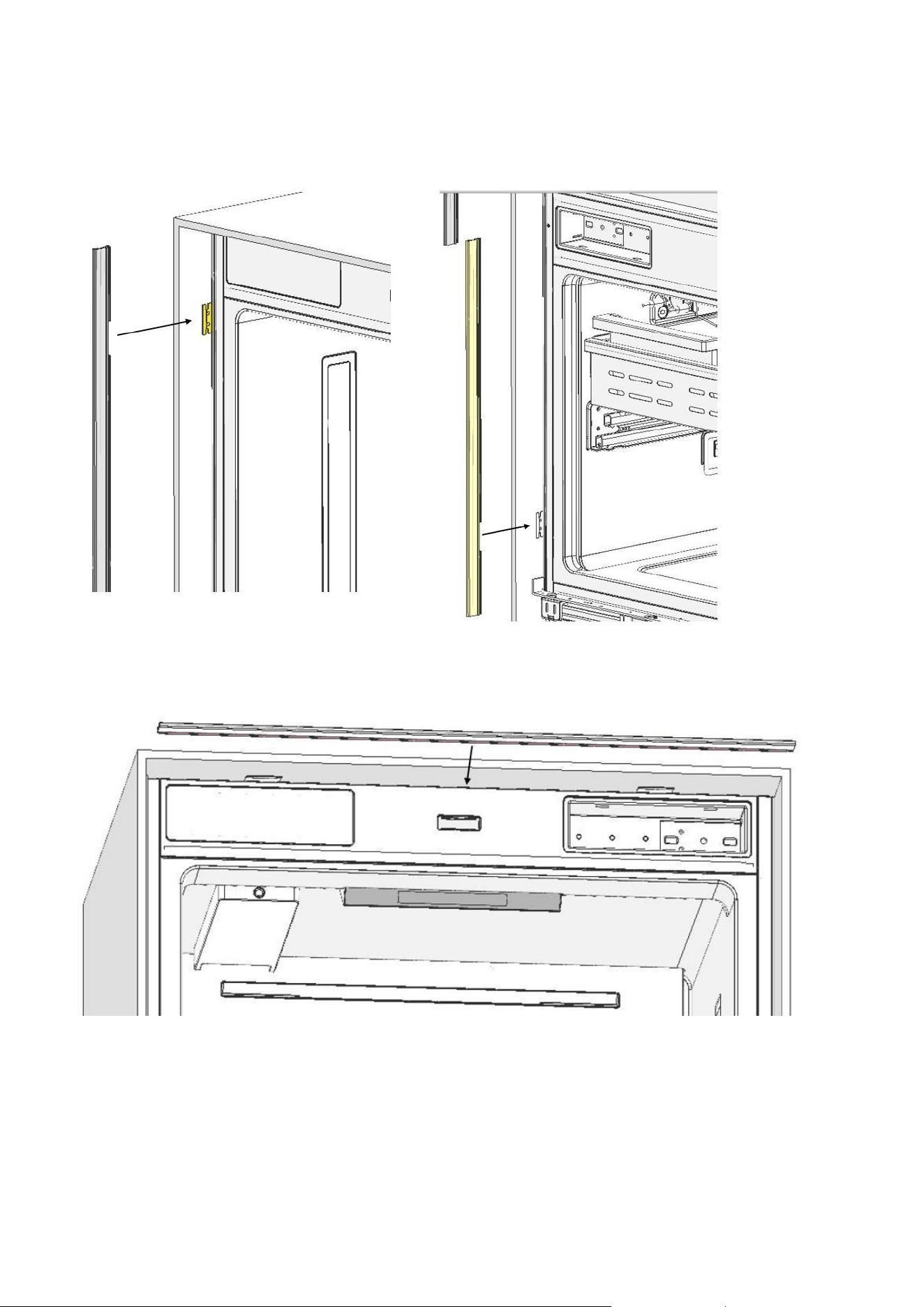
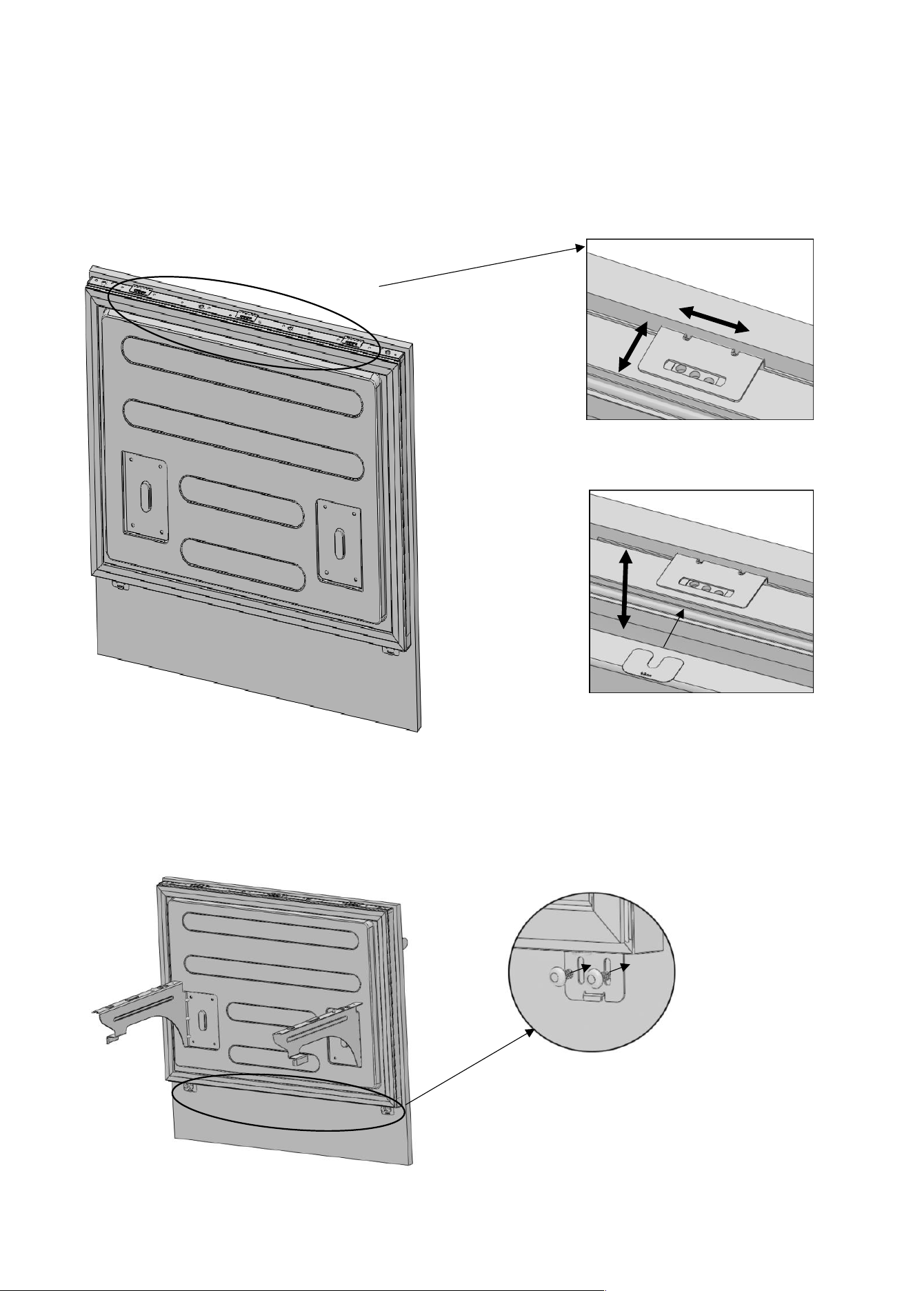
Attaching the upper vent hole part
⚫ Use 2 screws to attach the upper vent hole part.
48
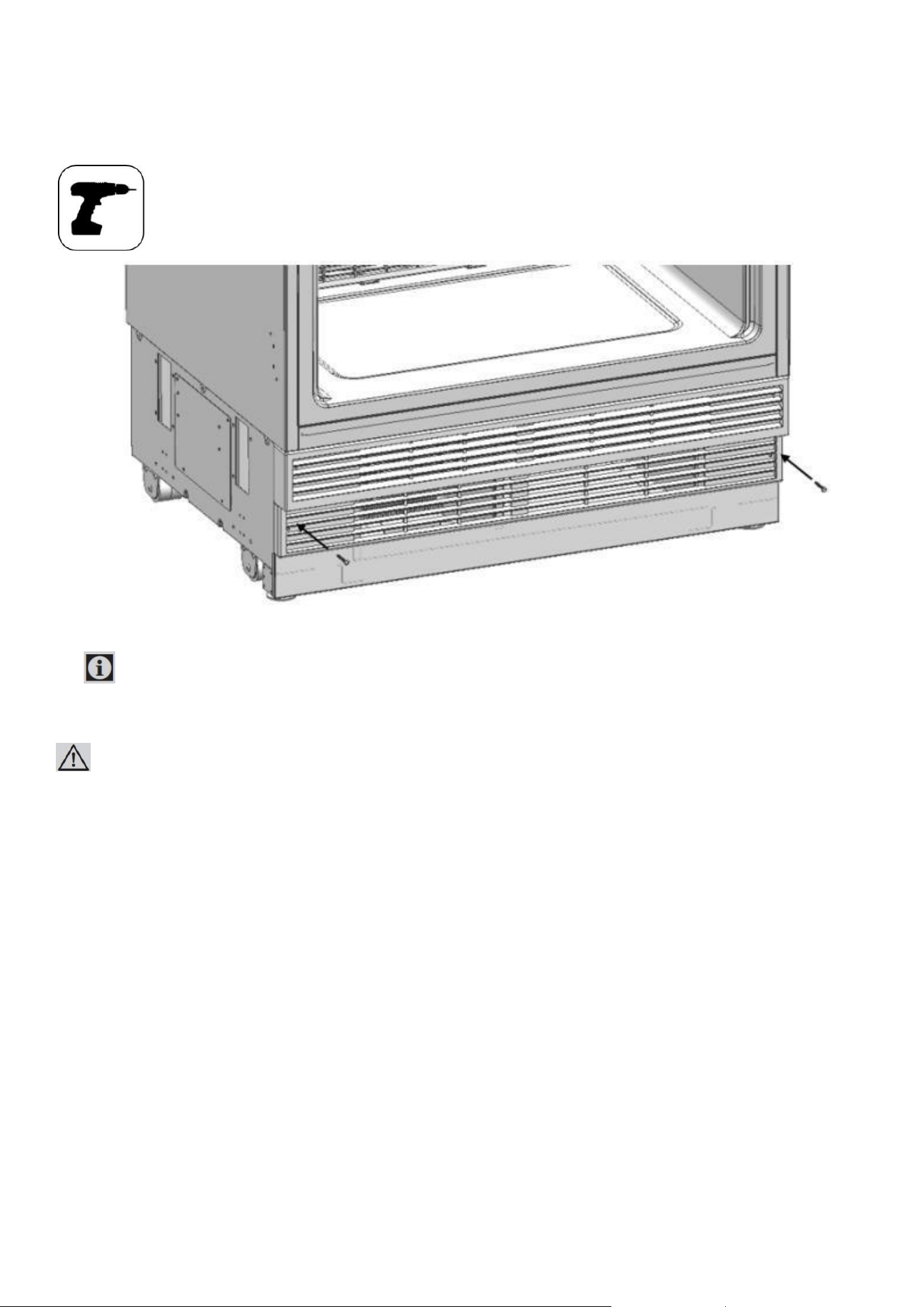
Attaching the lower vent hole assembly
⚫ Use 2 screws to attach the lower vent hole part.
IMPORTANT INFORMATION:
You can move the lower vent hole forward-backward to adjust it to the kick plate in the kitchen.
WARNING:
Forward-backward travel distance of the lower kick plate must be 15/16" (23 mm).
As you can see in the figure, the decorative kick plate must not be in front of the upper vent hole level.
49
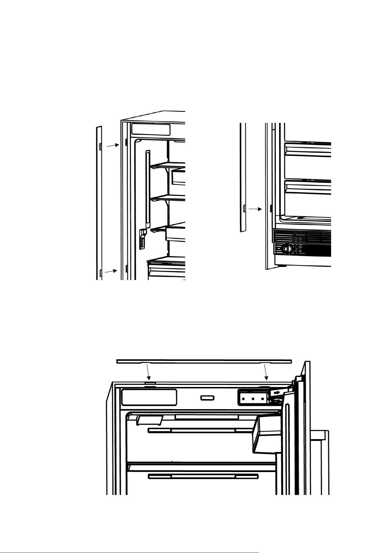
Attaching the decorative parts
⚫ Attach the trim fridge furniture side (Item No1) onto cabinet-cabin connecting bracket (Item No12).
⚫ Attach the trim furniture top (Item No4) onto cabinet-cabin connecting bracket (Item No12).
50
WARNING:
Maximum weights of the furniture to be mounted to the product are as follows.
Fridge Door: 35.7 lbs. (16.2 kg)
Freezer Door: 19.8 lbs. (9 kg)
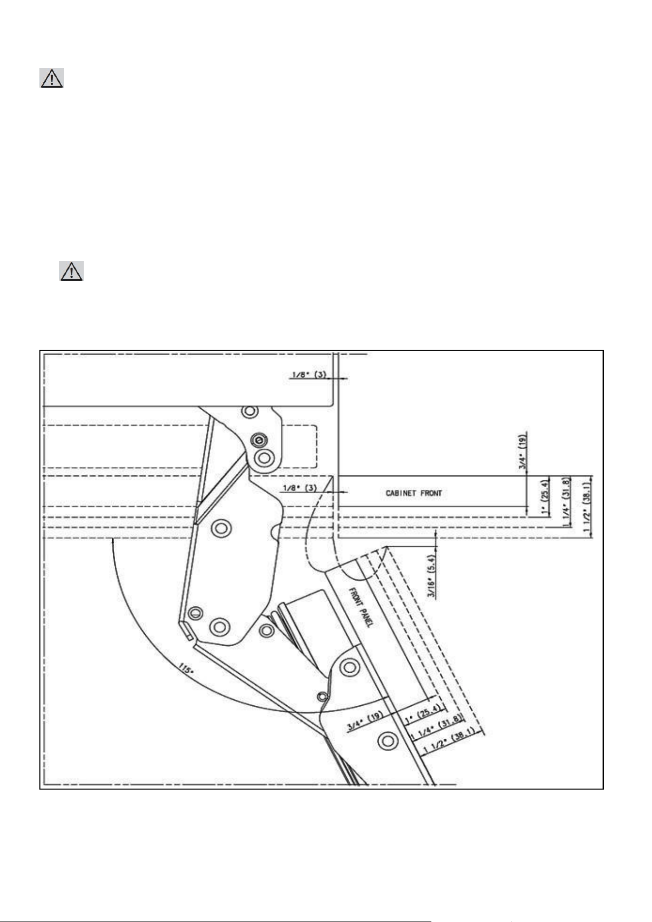
Choosing the Door Thickness
⚫ The door of your refrigerator can open by 115° maximum. If the door is going to open to this degree,
you can choose the following thickness levels.
WARNING:
If the door thickness is more than 1 ½” (38 mm), the door should not open more than 90°. You must use a
limiting pin on the hinge.
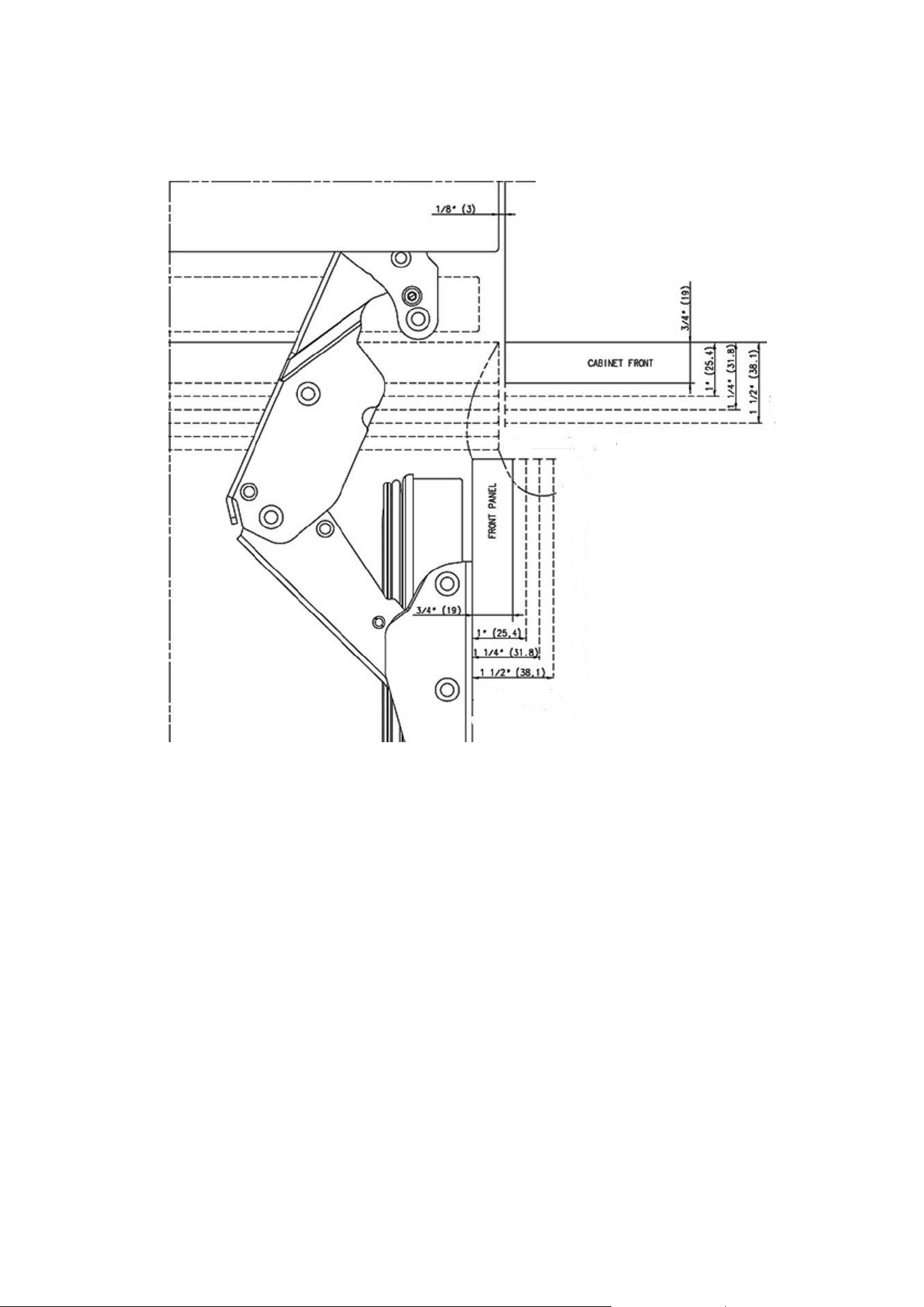
⚫ You can limit the opening degree of your door to 90° if you want.
In this case, the door thickness levels can be like the following (you can look at the relevant section to learn
51
how to attach the 90° limiting pin (Item No6).
FURNITURE DOOR PREPARATION
This section contains information about preparing the furniture doors and mounting them to the product.
52
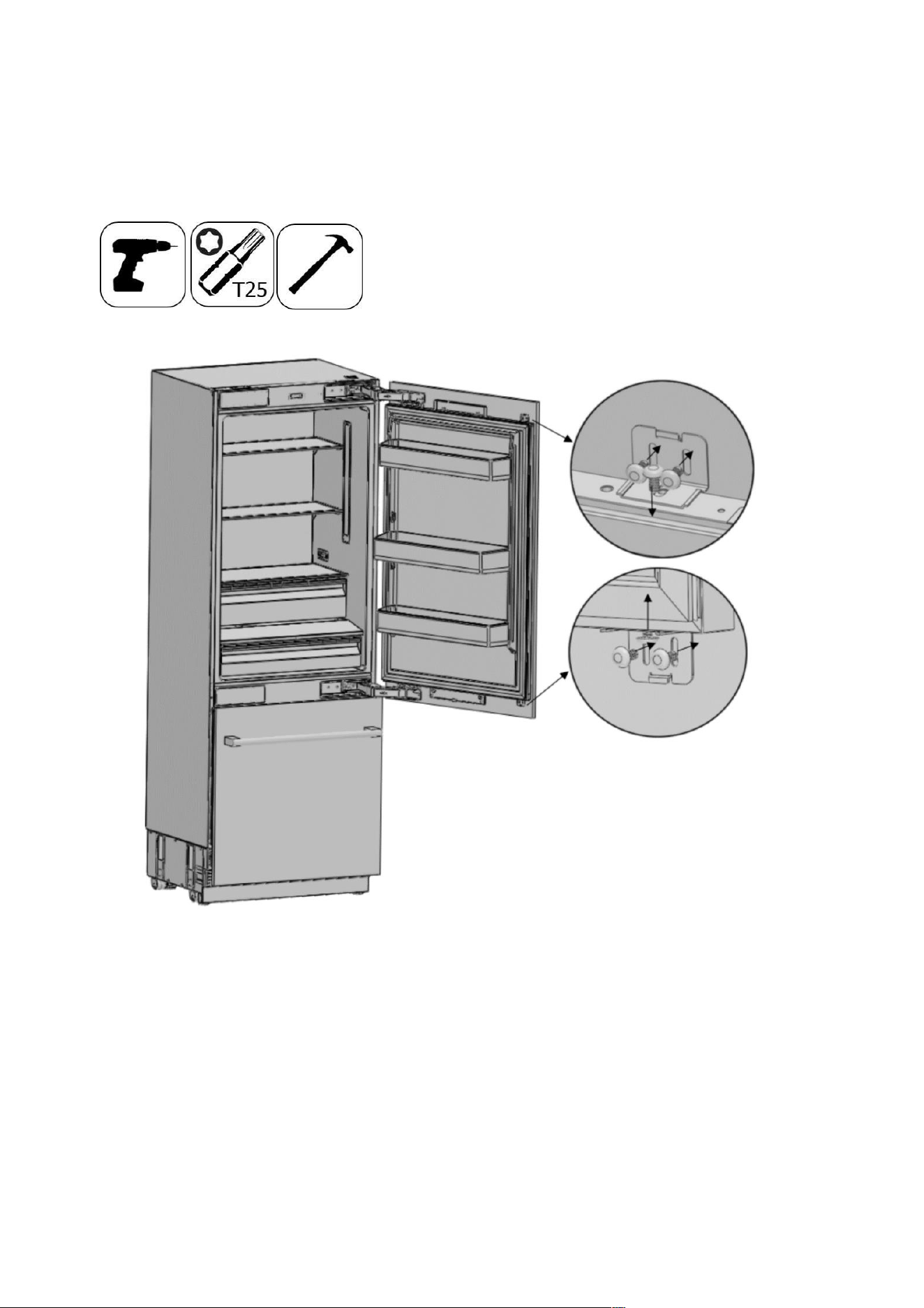
Removing the Mechanism Covers
⚫ Remove screws to take out the cover door hanger bracket upper and fixing bracket.
⚫ Remove two screws to take out the cover door hanger bracket low.
Removing the Panel-
53
Adjustment Mechanisms on the Refrigerator
⚫ Remove the upper and lower Adjusting Mechanism assemblies from the door.
54
Preparing Furniture Door
IMPORTANT INFORMATION:
You must take the dimensions into account when grouping the cradle parts on the furniture door.
When marking, you can use the "Furniture door preparation template" (Item No 1) provided
with the product.
WARNING:
Handle connection holes must be adjusted according to the handles to be used in kitchen design.
WARNING:
Minimum thickness of the door must be ¾" (19mm).
55
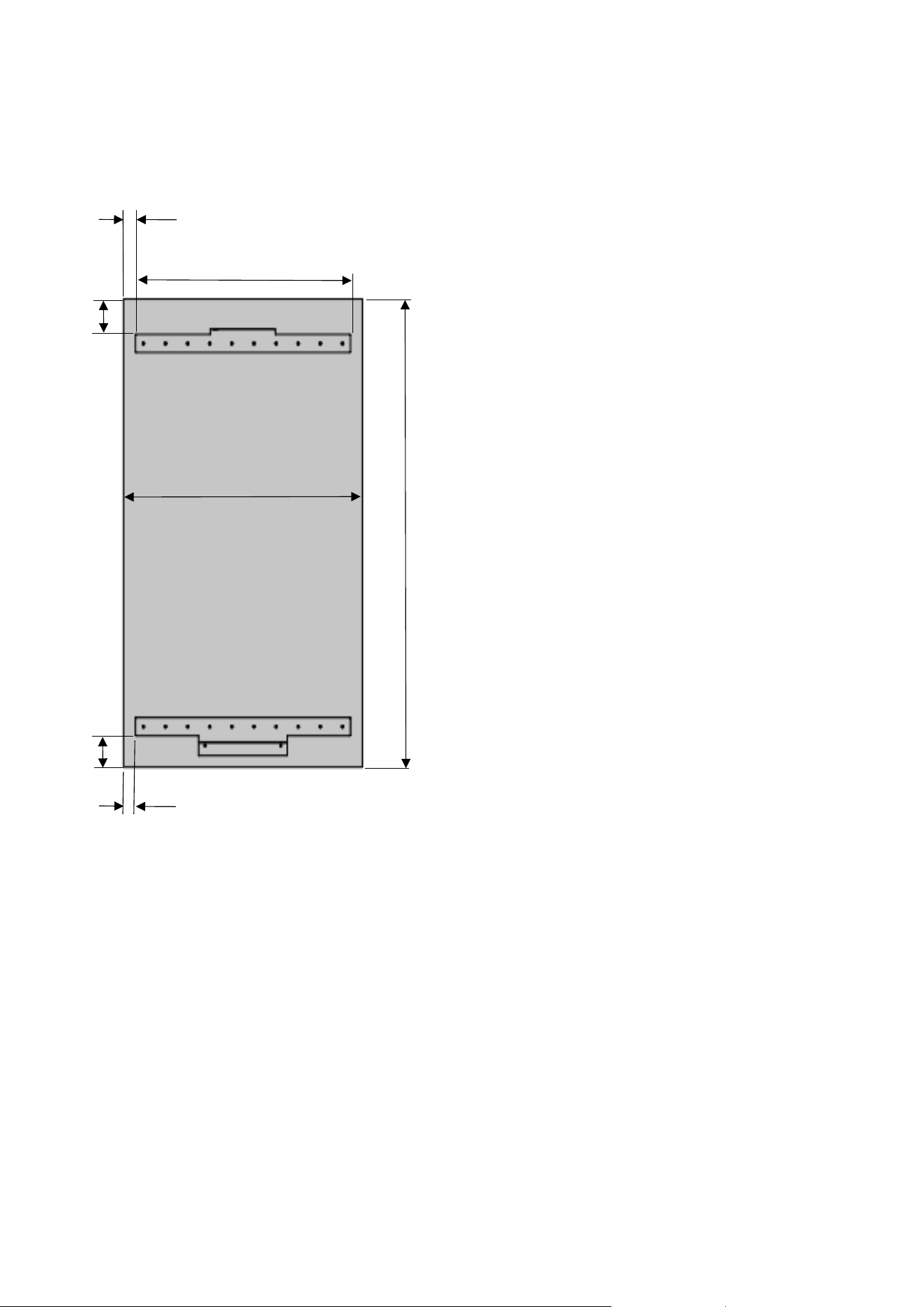
Preparing the Fridge Furniture Door
76:1 7/16” (38mm)
91:4 7/16” (114mm)
76:29 3/4“ (756mm)
91:35 3/4“
(908mm)
51 1/16” (1297mm)
3 7/16” (87mm)
26 13/16”(680mm)
3 13/16” (98mm)
AINT7600/AINT7600IW
AINT9000/AINT9000IW
76:1 7/16” (38mm)
91:4 7/16” (114mm)
56
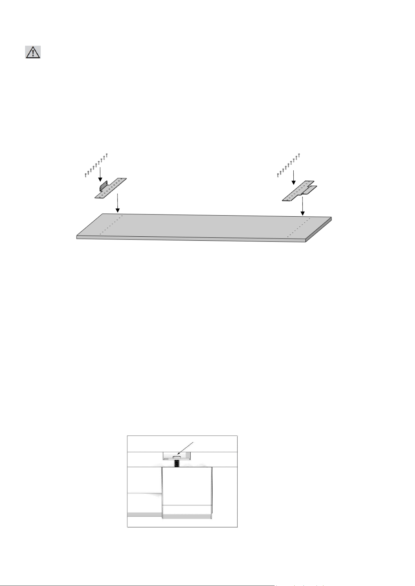
WARNING:
You must use screws suitable for the door thickness.
⚫ Install 2 hanger bracket using the screw furniture door hanger bracket (Item No18).
You can also use the furniture door preparation template (Item No 1) provided
with the product to align these parts.
It is recommended to keep this template for future reference.
⚫ Attach the fridge door handle.
Screws holding the door handle must not protrude.
AINT7600/AINT7600IW
AINT9000/AINT9000IW
Preparing the Freezer
57
Furniture Door
AINT7600/AINT7600IW
AINT9000/AINT9000IW
2 9/16” (65mm)
1 7/16” (37mm)
28 11/16“ (729mm)
76:29 3/4 “ (756mm)
91/92:35 3/4” (908mm)
58
WARNING:
Handle connection holes must be adjusted according to the handles to be used in kitchen design.
WARNING:
Minimum thickness of the door must be ¾" (19 mm).
WARNING:
You must use screws suitable for the door thickness.
⚫ Install hanger bracket using the screw furniture door hanger bracket (Item No18).
You can also use the furniture door preparation template (Item No 1) provided
with the product to align these parts.
It is recommended to keep this template for future reference.
⚫ Attach freezer door hanger brackets (Item No9) using 6 screws (Item No18) for each.
⚫ Attach the freezing door handle.
Screws holding the door handle must not protrude.
59
INSTALLING THE FRIDGE FURNITURE DOOR
1. Attach the furniture door to the fridge door
How to align the fridge
60
door with bolts.
Position of the Furniture Doors to the kitchen furniture must be flush.
To achieve this, you should adjust 3D direction using by two fixing bolt to perform fine adjustments.
First of all, review the position of the grouped Furniture Doors against the kitchen furniture.
Distances between furniture must be 1/8" (3 mm), assuming that the furniture dimensions are correct.
You can make door adjustments based on this distance.
• How to align the furniture door upper part with bolts.
Front & back
Left & right
Up & down
Fixing furniture door completely
• How to align the furniture door lower part with bolts
61
.
Up & down
Left & right
Fixing furniture door completely
Front & back
• Use the door-door furniture connecting bracket (Item No16) to join th
62
e furniture door
• Use 1 screw door fixing bracket (Item No15) to fix on the door.
• Use 2 screws (Item No17) to fix on the furniture door.
AINT7600/AINT7600IW
AINT9000/AINT9000IW
• Clip the cover furniture door bracket (Item No14)
63
.
AINT7600/AINT7600IW
AINT9000/AINT9000IW
• Attach and screw the upper/lower decoration
64
cover.
WARNING:
There is a magnet on the cover door hanger bracket upper.
This is a functional part for the operation of the product.
It should not be confused with the lower cover.
AINT7600/AINT7600IW
AINT9000/AINT9000IW
INSTALLING THE FREEZING
65
FURNITURE DOOR
• Attach door-door furniture connecting bracket (Item No16) on the door lower part
with screw door fixing bracket (Item No15)
⚫ Attach the furniture door to the freezing door
• How to align the freezing
66
furniture door lower part
• How to align the furniture door upper part with screw freezer door hanger bracket (Item No8).
• Use the door-door furniture connecting bracket (Item No16) to join the furniture door
• Use 2screws (Item No17) to fix on the furniture door.
Front & back
Left & right
Up & down
67
• Clip the cover furniture door bracket (Item No14).
.
WARNING:
You must keep these parts for future use. You will need them if you want to change the door directions.
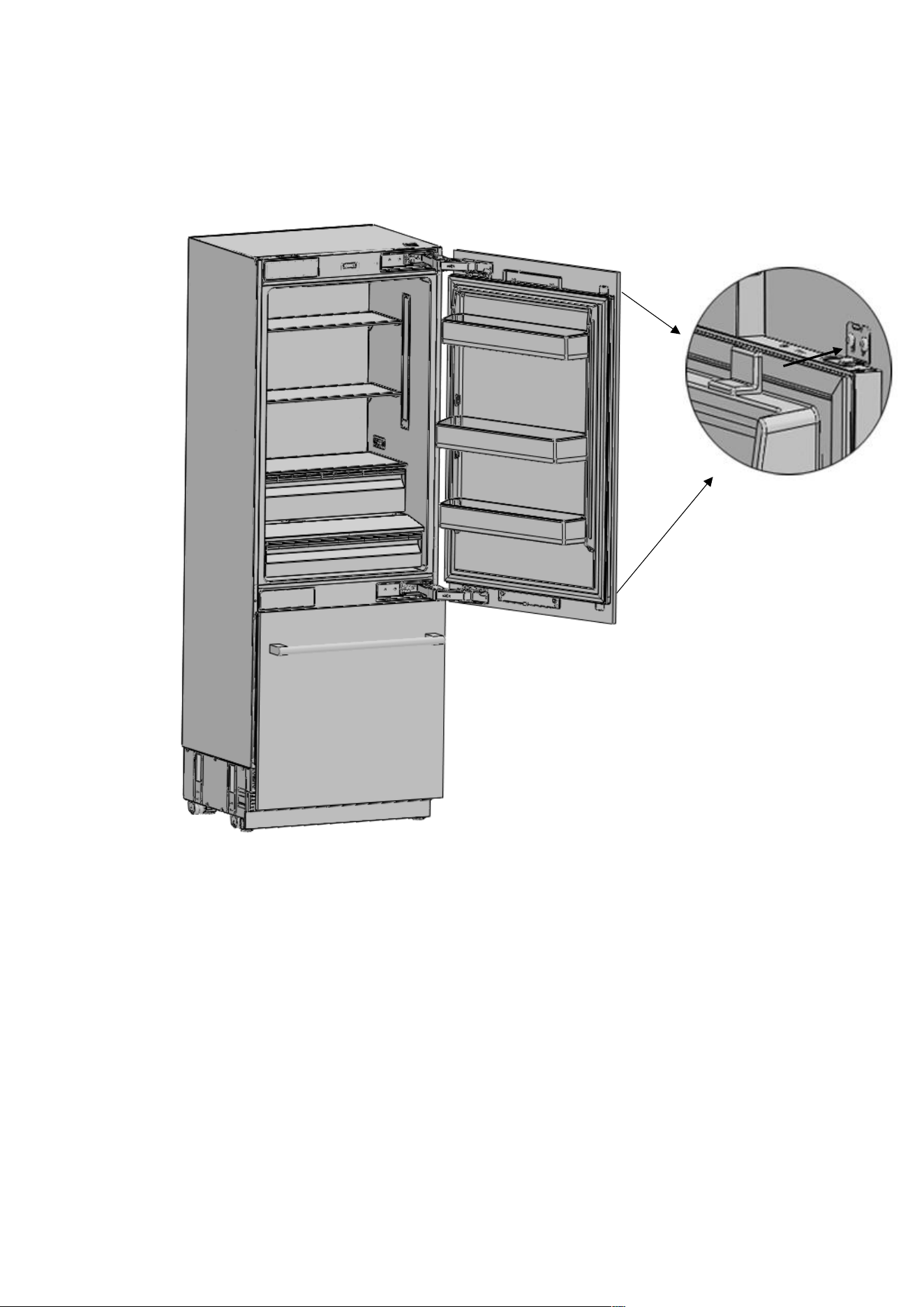
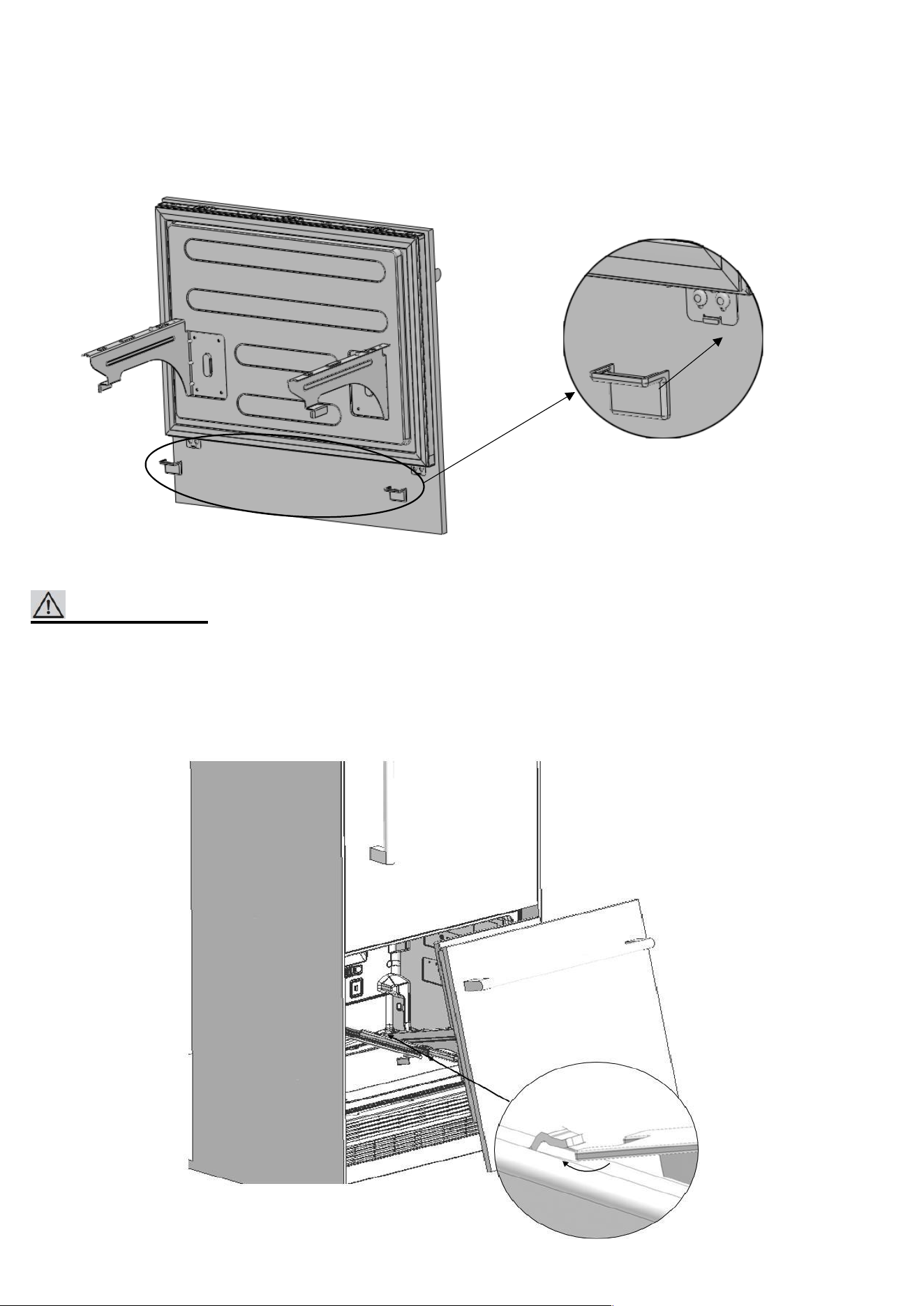
• Install the Freezer Furniture door assembly onto the rails.
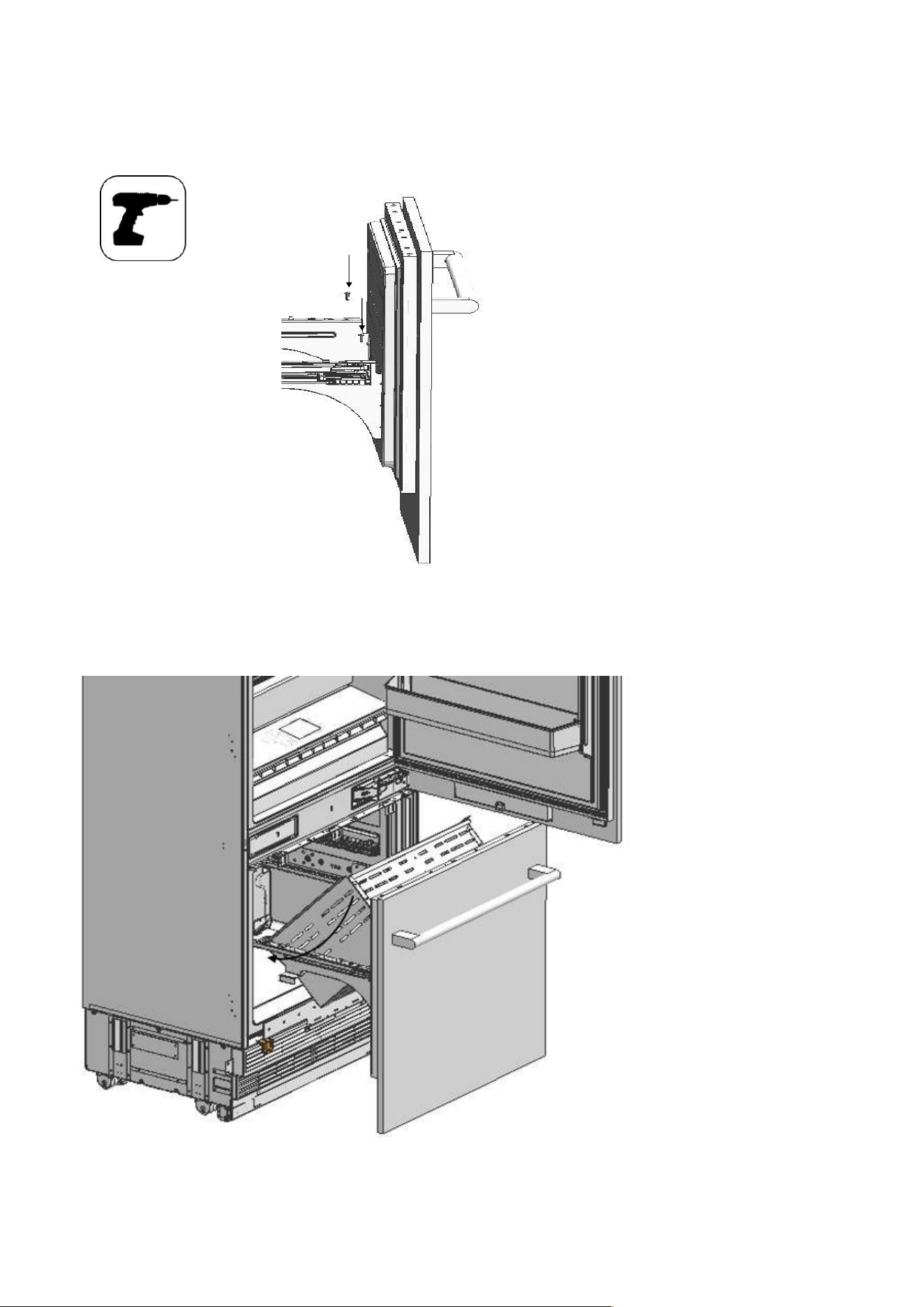
• Fix the Freezer Furniture door assembly onto the rails with 2 screws.
• Locate the drawer onto the rail and tighten the screws
68
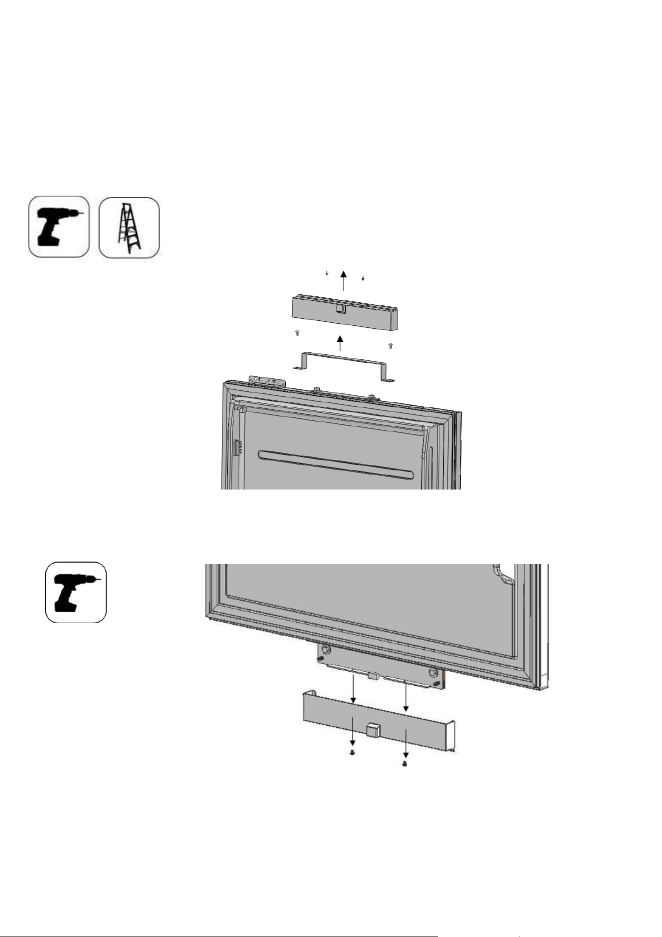
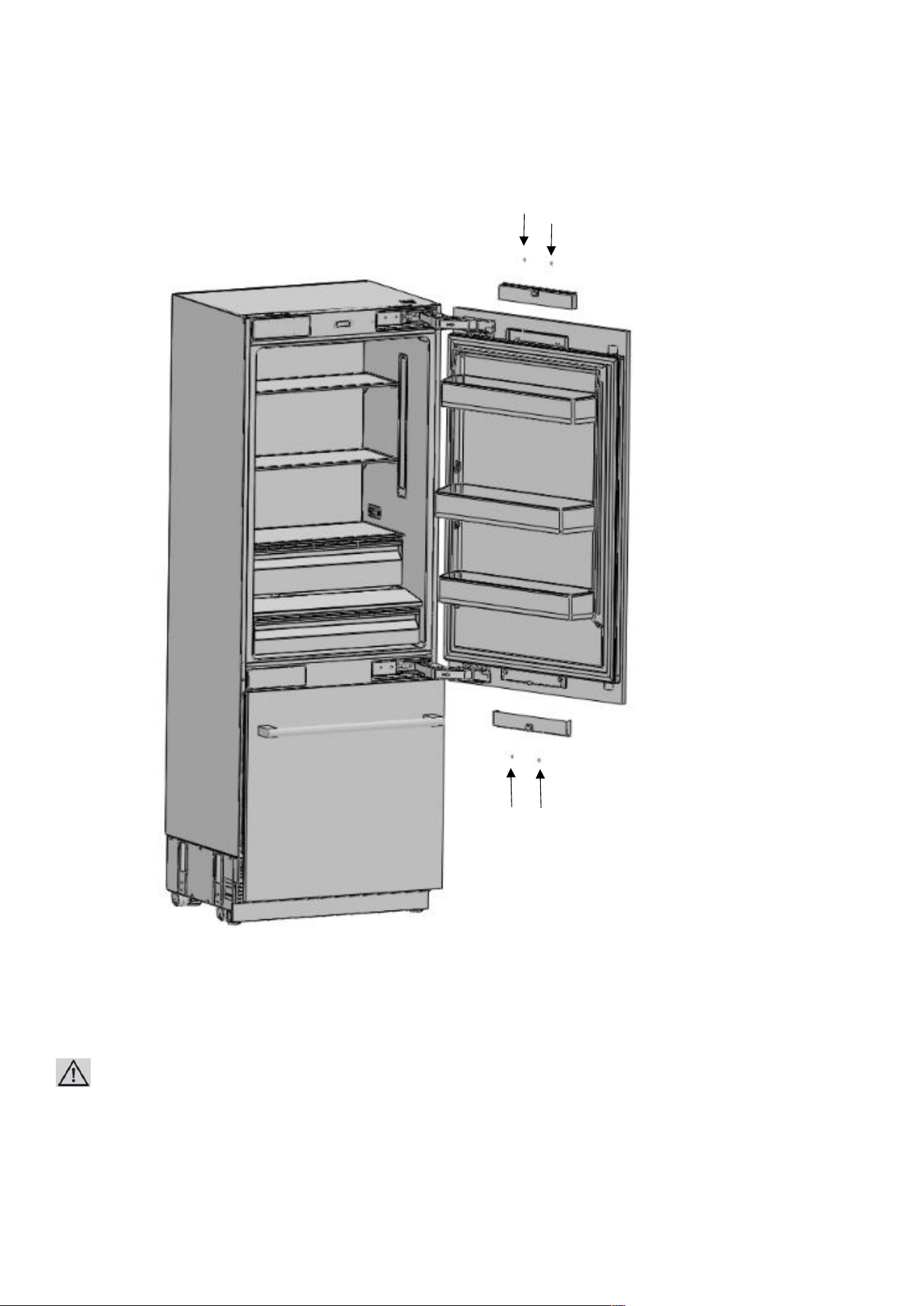
• Attach the cover freezing door top (Item No5) using the
69
tabs.
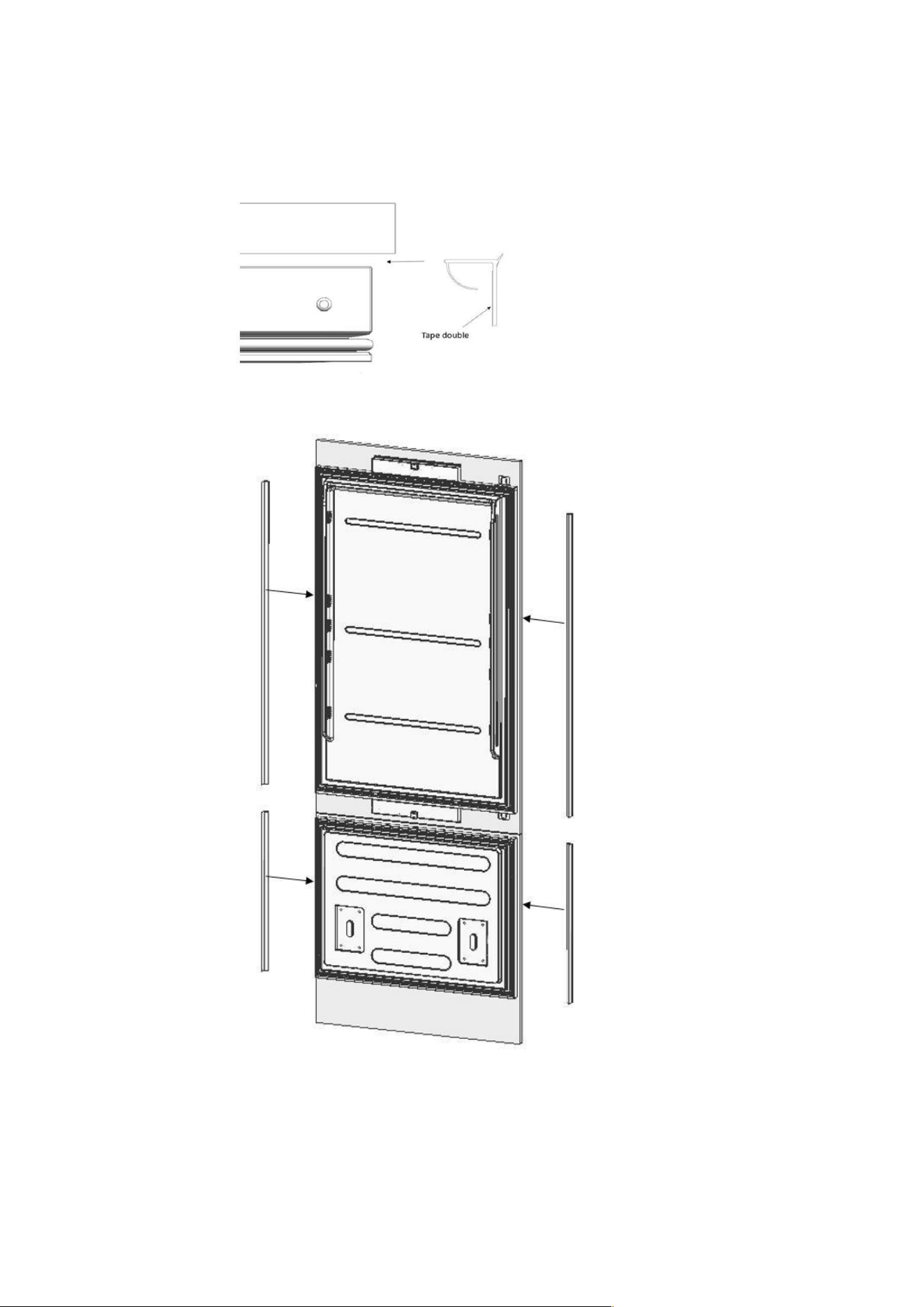
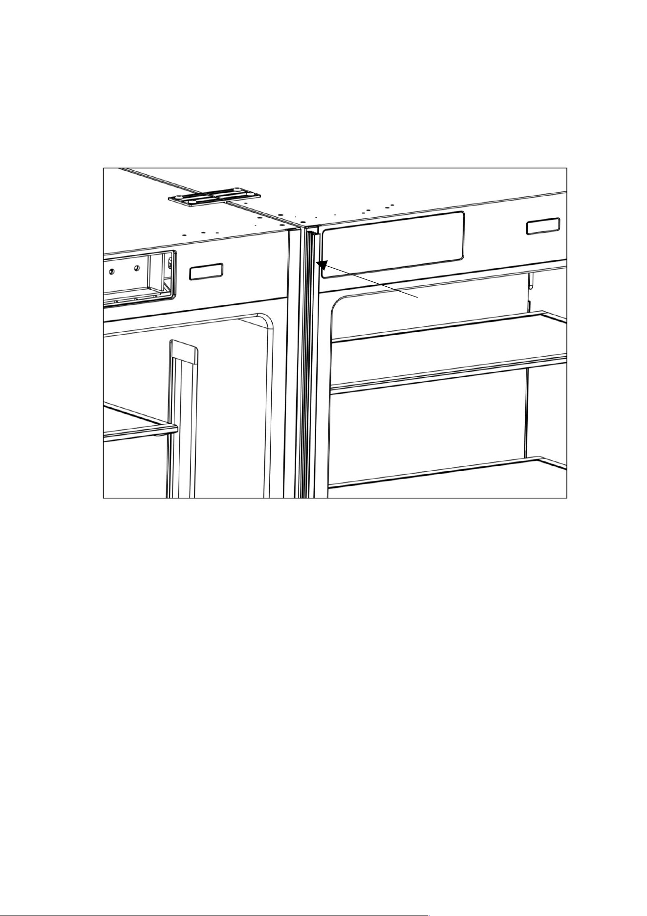
•
70
Attach the Trim door side (Item No2,3)
The backing paper of the double-sided tape should be removed before attaching the parts.
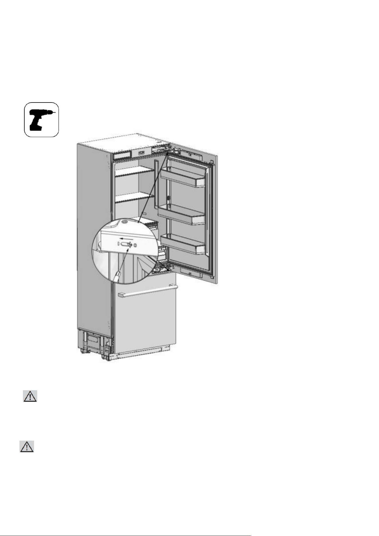
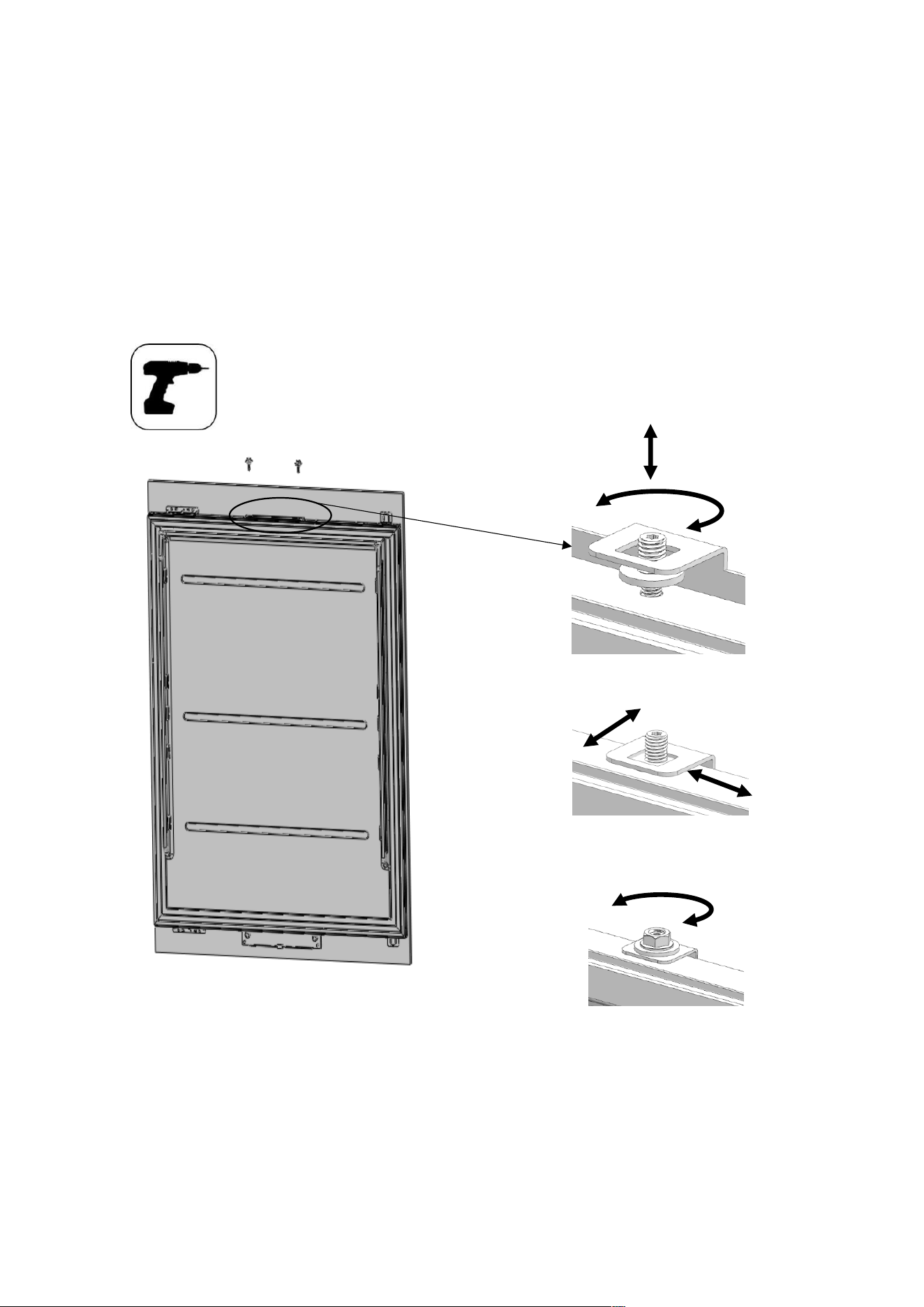
HINGE ADJUSTMENT
71
Adjusting the hardness of the hinges
• Use a drill to adjust the hardness of the upper and lower hinges of the fridge door.
Set the hinge adjustment screw to position "I" from position "O".
WARNING:
The door must be fully open during this adjustment.
WARNING:
This adjustment must definitely be performed after the door has been adjusted.
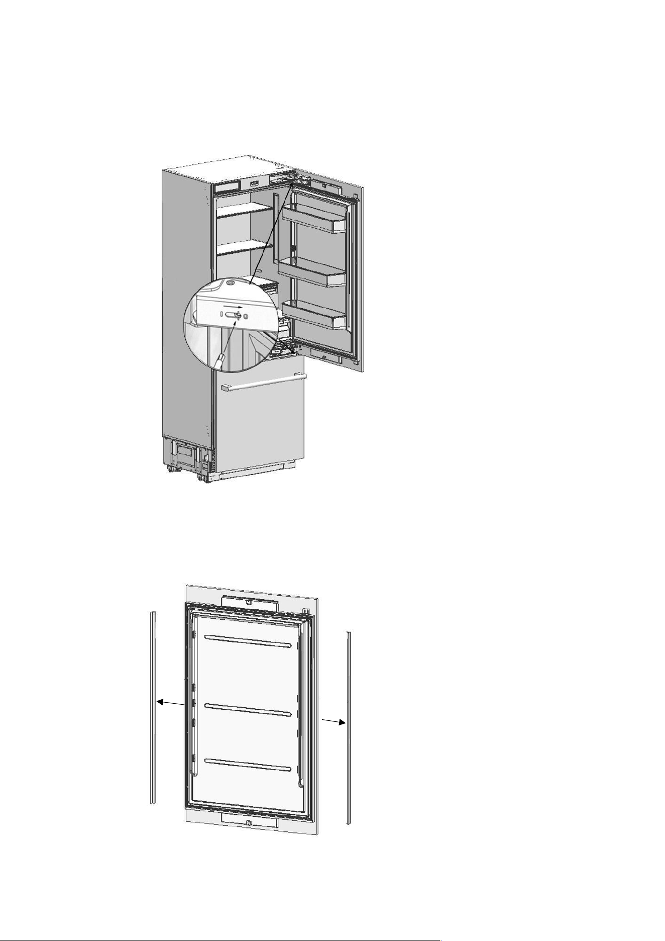
CHANGING DIRECTION OF THE FRIDGE DOOR
72
Removing the fridge furniture door
• Set the hardness level of the hinge to "0".
ATTENTION:
Failure to set the hinge to "0" and continuing the installation like that may cause injury.
• Remove the trim fridge furniture side
• Loosen 2 screws of the upper cover of the fridge door and remove
73
it.
• Remove the upper adjustment kits
• Loosen 2 screws of the lower cover of the fridge door and remove it.
• Remove fridge lower and upper bracket and fixing
74
screws.
AINT7600/AINT7600IW
AINT9000/AINT9000IW

75
WARNING:
The clad door will be released when these screws are removed.
You must take measures to prevent the door from falling.
You can tape the Furniture Door to the Inner Door or ask for help from another person.
• Take the Fridge Furniture Door and lay it down on a table upside down.
• You must attach the Furniture Door by rotating it 180° based on its current position.
Removing and preparing the Fridge Inner Door
• Remove the hinge connection screws of the Hinge
76
Brackets.
ATTENTION:
The clad door will be released when these screws are removed. You must take measures
to prevent the door from falling.
You can tape the Furniture Door to the Inner Door or ask for help from another person.
• Take out the fridge door and lay it down on a table remove the fixing parts and
screw them to the opposite side of the door as shown figure.
77
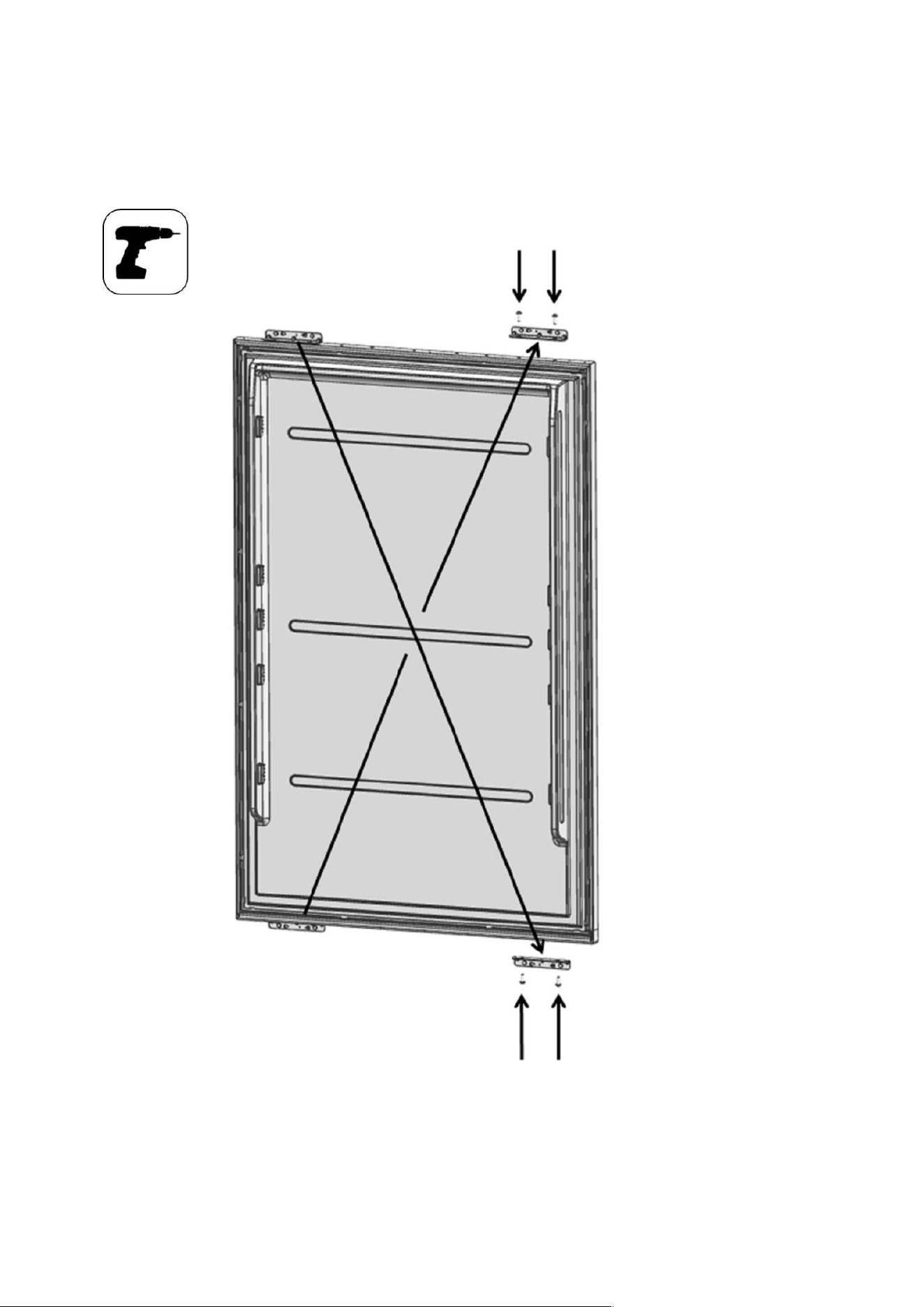
Replacing the hinges
• Remove the Hinge Caps located at the other side where you will fix the hinges.
78
• Remove the lower right hinge by loosening its 2 screws and fix it to its slot at the upper left side.
79
• Remove the upper right hinge by loosening its 2 screws and fix it to its slot at the lower Left side
80
81
• Attach the Hinge Slot Caps removed from the left side to the Hinge Caps at the right side.
Installing the Fridge Door
• Place the Fridge Door to the refrigerator and fix it with 4 screws.
82
83
INSTALLATION DUAL CABIN
If you are going to make a dual cabin installation, you must definitely demand "Dual Cabin Installation Kit"
from the authorized service.
The instructions below have been prepared according to Built-in type.
Built-in: The Appliance and Panels fully seat into the gap, and a material that can be their own box is jammed
between the two kitchen cabinets or decorative columns. This is the most common installation scenario.
Cabin Dimensions
Cabin dimensions below must be checked before starting the installation.
√ Dual cabin dimension
Category 76+76 76+90 90+90
“A” Dimension 60” (1524mm) 66” (1676mm) 72” (1828mm)
“A”
84” (2134mm)
25
84
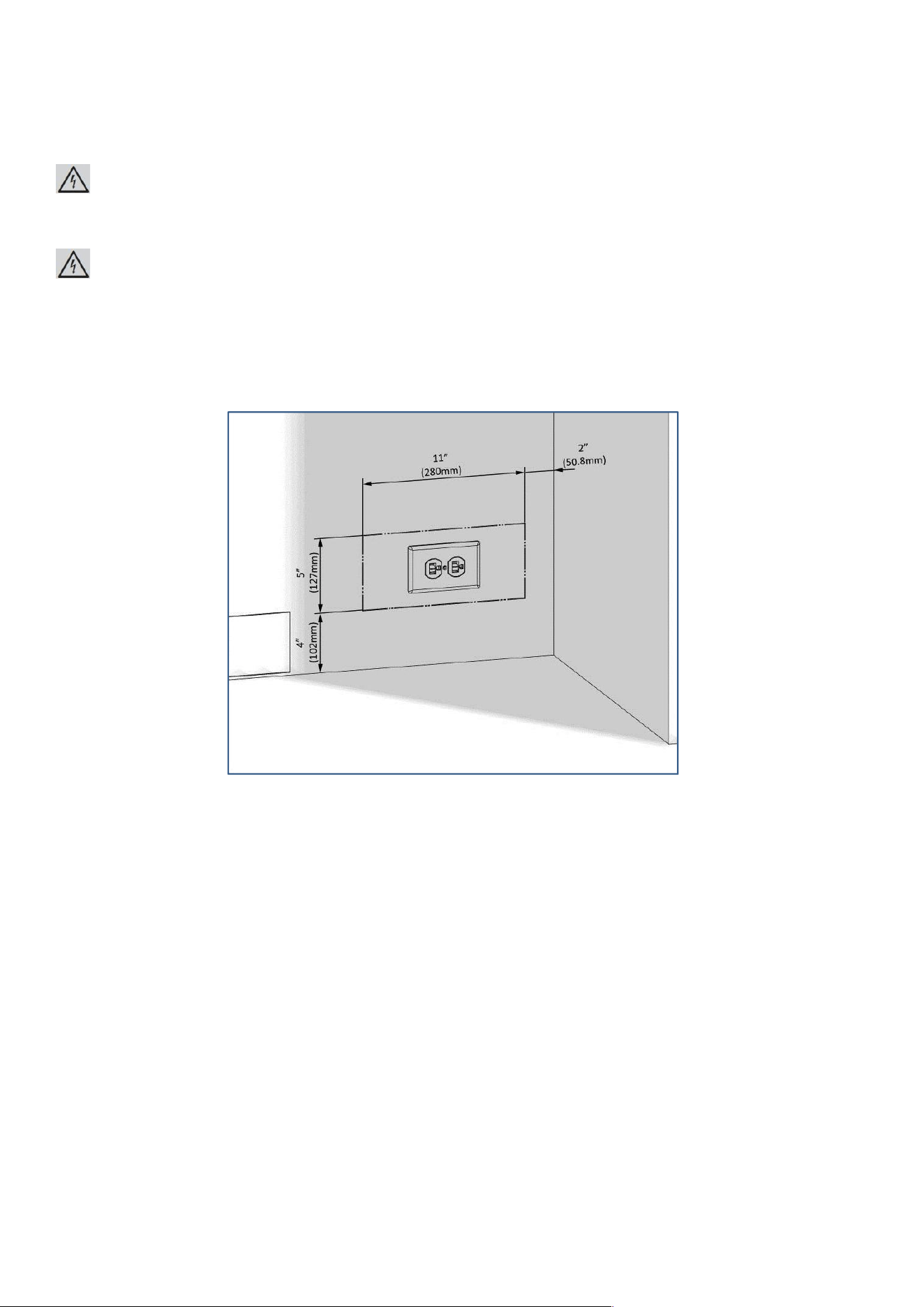
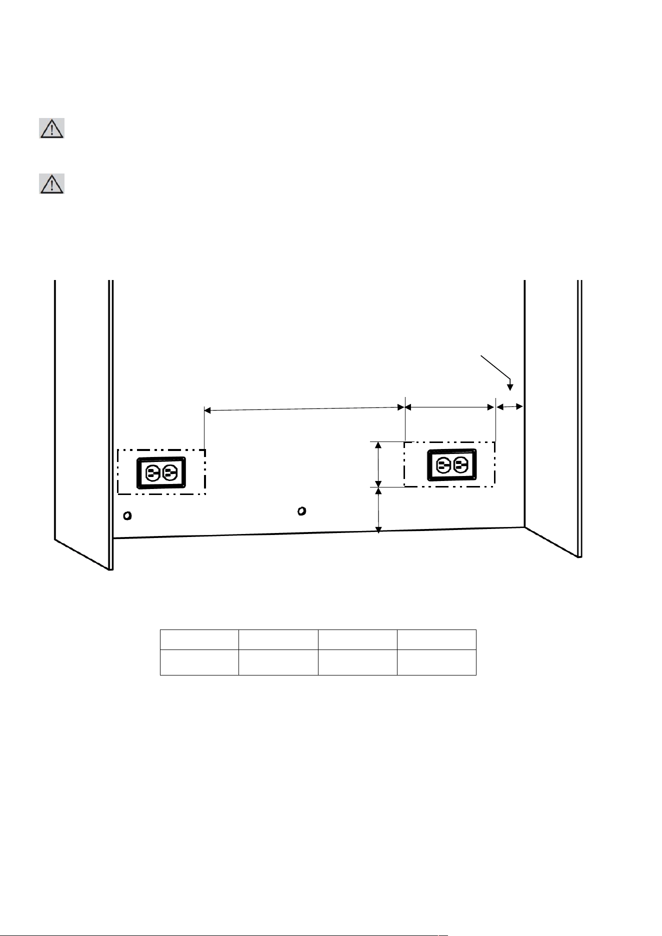
Location of the Electrical Wiring
Location of the electrical wiring must be within the range given below.
ATTENTION:
Do not use extension cables or two-pin adaptors and do not remove the ground terminal of the grounding cable.
ATTENTION:
A qualified electrician must ensure that the poles of the socket are connected correctly. Verify that
the grounding of the socket is correct.
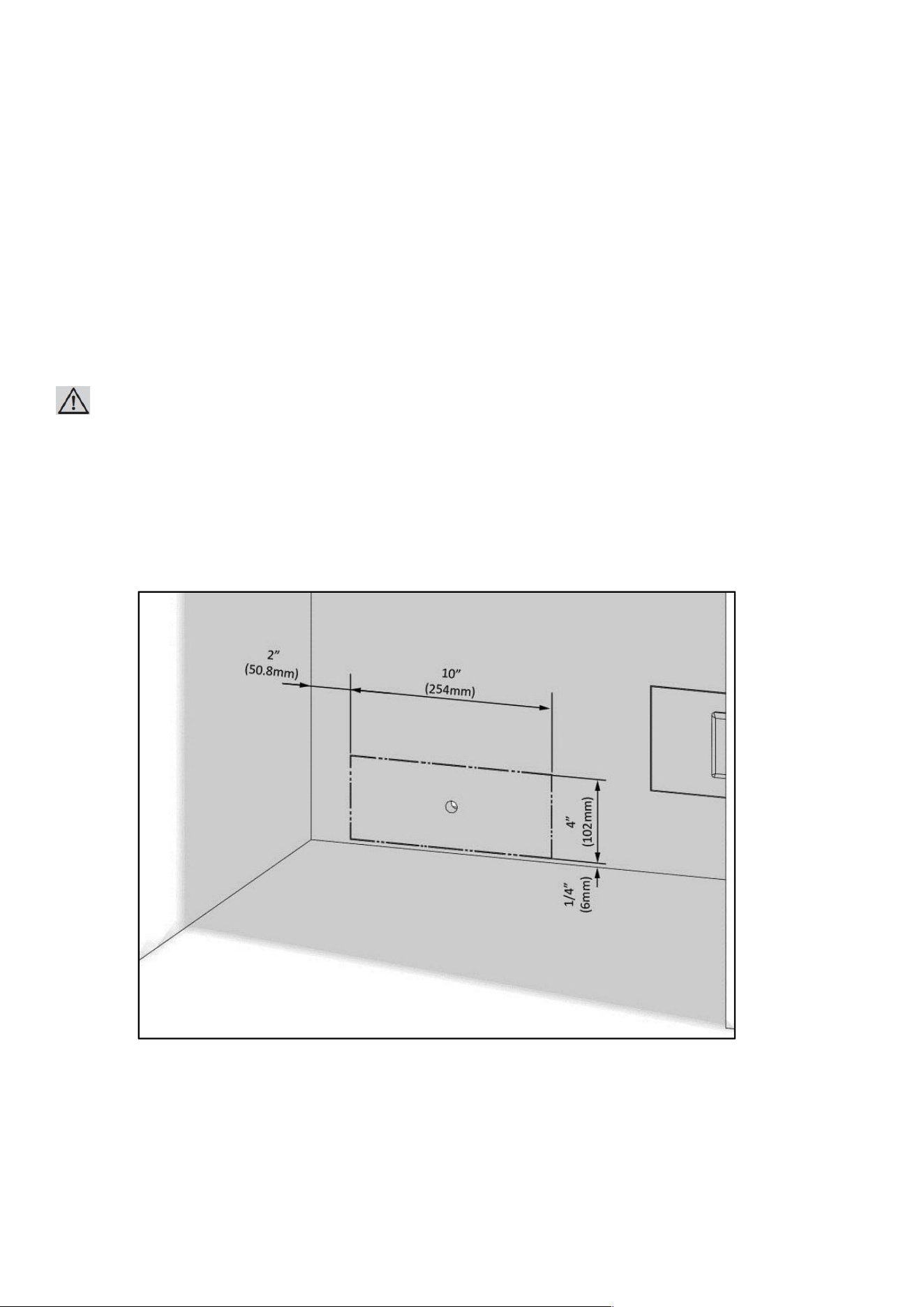
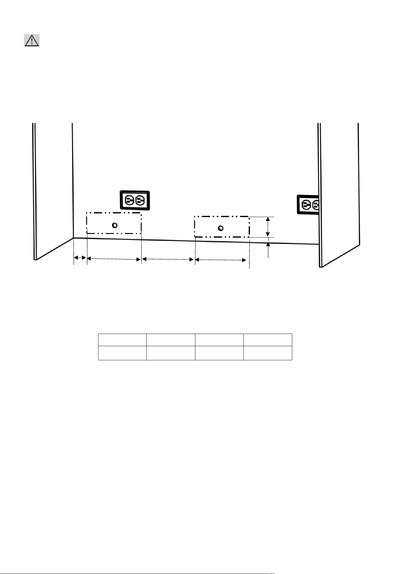
Location of the water system
The water connected to the water mains must be potable.
Location of the water system must be within the range given below.
Water system of the refrigerator must be connected to the water mains system in the house.
The user must be able to switch it on/off with the valve when necessary.
Objects that might pierce the water hoses or cause them to twist must not be present
where the water line is installed.
Pressure of the water system must be between 25-80 psi (1.7-5.5 Bar).
If the water pressure exceeds 80 psi, install a pressure limiting device or water impact protector to the inlet valve.
Never install the product or operate the appliance if it is possible for the water pressure to exceed 120 psi.
Category 76+76 76+90 90+90
“A” Dimension
19 1/8”
(485mm)
25 1/16”
(637mm)
25 1/16”
(637mm)
2 “ (50.8mm)
11 “ (280mm)
“A”
5”
(127mm)
4”
(1
02
mm)
85
WARNING:
Make sure that there is no water leakage when making the water connections.
Otherwise, there will be water on the floor and the furniture will get damaged.
You will need a hose with a minimum length of 60" (1.5 meters) and a diameter of ¼"
for water connections of the product during installation.
A connector that has a thread with an external diameter of ¼ must be used to connect the hose end to the product.
Before completing the installation, make sure that water flows and there is no water leakage.
Category 76+76 76+90 90+90
“A” Dimension 20” (508mm) 20” (508mm) 26” (660mm)
4” (102mm)
2“ (50.8mm)
10“ (254mm)
7/8”
(21mm)
A “
10“ (254mm)
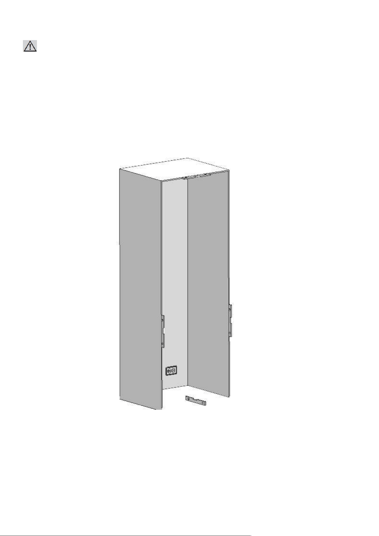
86
Mounting Part list
Stick the Insulation Sponge (Item No1) to the side panel so that the sponge remains in between two cabins.
No Part name Spec Q’ty Remark
1 Insulation sponge Sponge, gray, T3.0*400*1750 1
2 Connecting bracket T2.0, Cr+zn-coating 2
3 Truss washer head M4*12 16
4 Fastener POM 3
5 Trim furniture middle PVC extrusion L=1876 1
Truss washer head screw
Spec : M4x12
Fixing Refrigerator
Such as cabinet and door
(press part)
87
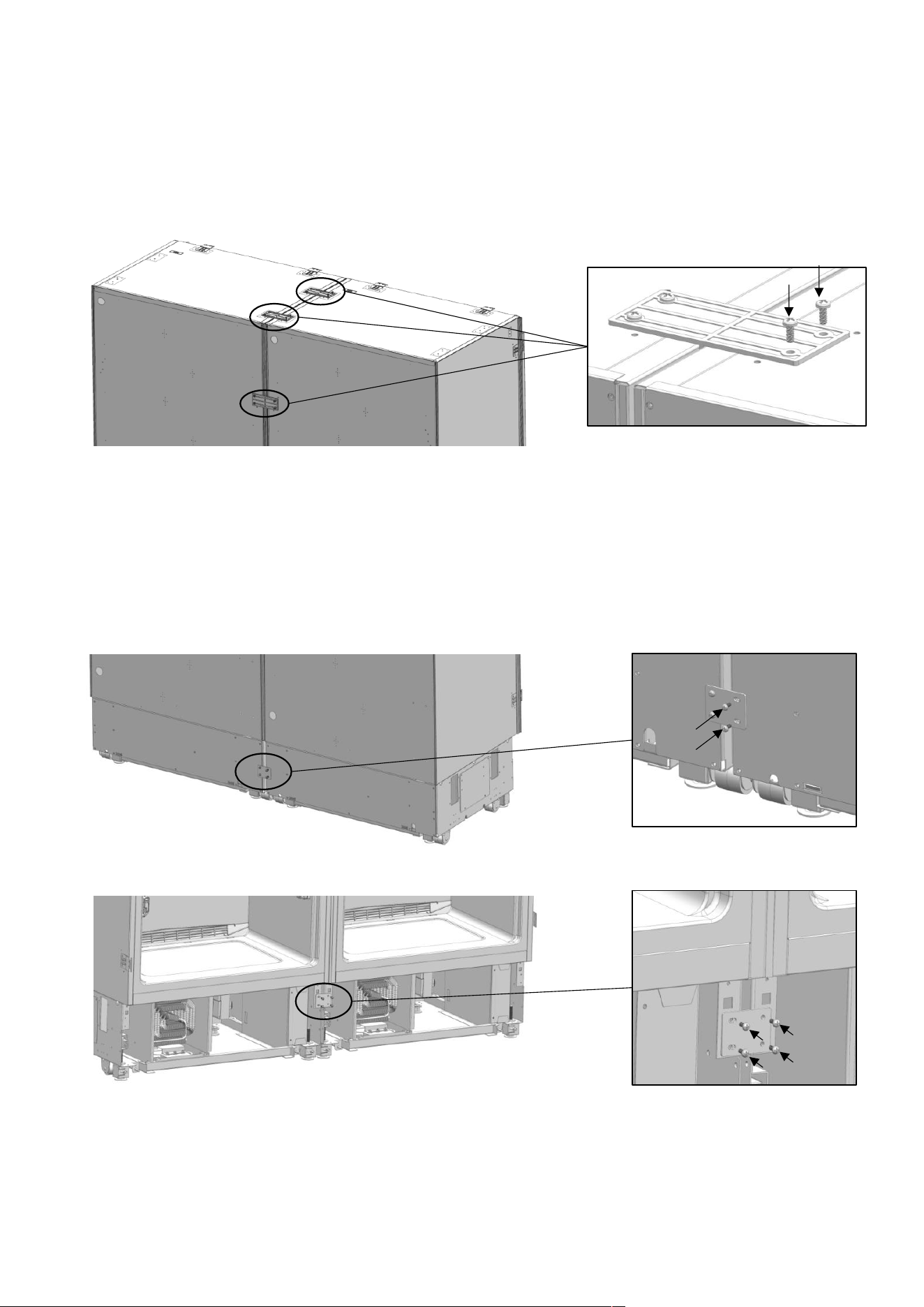
Attaching the fasteners and connecting bracket
Screw the connecting bracket(Item No2) and fasteners (Item No4) that are going
to connect two refrigerators together.
Connecting bracket
Fastener
60
55
Insulator
T3.0*400*1750
Insulator
88
Make power and water connections of the refrigerator as explained before.
After making sure that they are in alignment Screw the upper brackets to the other refrigerator.
After making sure that they are in alignment screw the lower brackets to the other refrigerator.
89
Adjusting the height of the refrigerator in the cabin
Adjust the refrigerator height using the adjustable feet.
WARNING:
First of all, raise the front feet to reduce the risk of the cabin falling frontward.
A/D –Turn the key clockwise to lift the front
B/C –Turn the key clockwise to lift the rear
Screwing the bracket
90
furniture on the cabin side wall
Attach the cabinet- cabin connecting bracket to the furniture with 12screws.
Screwing the bracket furniture on the cabin top wall
⚫ Attach the cabinet- cabin connecting bracket to the furniture with 4screws.
91
Attaching the decorative parts
Attach the trim furniture side onto the Cabinet- cabin connecting bracket.
Attach to the trim furniture top onto the Cabinet- cabin connecting bracket.
Attach the trim furniture middle ( Item
92
No5) between two refrigerators.
Refrigerator
User Manual
AINT7600
AINT7600IW
V202300828
Please read this manual before using the product!
Dear Valued Customer,
We wish you to get the best results from your product that has been
manufactured meticulously at modern plants and tested with detailed
quality control checks.
For this reason, we recommend that you read this user manual
thoroughly before starting the product.
If you hand over the product to someone else, please remember
to give the user manual as well.
This manual will help you use your appliance in a fast and safe way.
• Please read this user manual carefully before installing and using the product.
• Always follow the applicable safety instructions.
• Keep the user manual in an easily accessible place for further use.
• Please read all the other documents provided with the product.
Please keep in mind that this manual may apply to several product models.
This manual expressly indicates the differences between various models
A
Risk of injury and property damage.
B
Risk of electric
shock.
C
Important information and useful hints.
Packaging materials of this product has been
manufactured from recyclable materials in
accordance
with the National Environment Regulations.
1 Important Instructions Regarding Safety and Environment
This chapter contains safety information that will help you avoid the risk
personal injury or property damage. Failure to follow these instructions shall
render any product warranty void.
1.1 General Safety
• This product can be used by children at age 8 and above and those people
who have limited physical, sensory or mental capabilities and people
who lack experience and information on the condition that they have been
given the instructions about the safe use of the product,
they are supervised and the risks have been eliminated.
Children should not play with the product.
Cleaning and care should not be performed by children unless
they are supervised by an adult.
• Unplug the product if you encounter a failure during use.
• If the product malfunctions, it must not be operated until repaired
by the authorized service provider. Risk of electric shock!
• Plug the product into a grounded socket protected by a fuse
that corresponds to the value on its nameplate.
Have a qualified electrician ground the product.
Our company cannot be held responsible for damages resulting
from the failure to use the product with a grounded socket pursuant
to local regulations.
• Unplug the product when not in use.
• Never wash the product by spreading or
pouring water onto it! Risk of electric shock!
• Never touch the plug with wet hands!
• Never unplug the product by pulling the cable.
Always pull the plug by holding the socket
• Do not plug the refrigerator if the wall socket is loose.
• Never connect your refrigerator to energy saving devices.
• Such systems are harmful to your product.
• Unplug the product during installation, care, cleaning and repairing procedures.
• Always have the Authorized Service Provider install the product and
establish its electrical connections.
The manufacturer cannot be held responsible for damages caused
by procedures performed by unauthorized persons.
• Do not eat cone ice cream or ice cubes immediately after you take them
out of the freezer compartment! This may cause frostbite in your mouth!
• Do not touch frozen food with wet hands! They may stick to your hand!
• Do not put bottled or canned liquid beverages in the freezer compartment.
They may burst!

1 Important Instructions Regarding Safety and Environment
• Never use steam or steam cleaners to clean or defrost the refrigerator.
Steam gets into contact with the live parts in your refrigerator,
causing short circuit or electric shock!
• Do not use mechanical devices or other means to accelerate
the defrosting process other than those recommended by the manufacturer.
• Never use the parts in your refrigerator such as the door and drawer
as a means of support or step.
This may cause the product to tip over or damage the parts of it.
• Do not damage the parts where the refrigerant is circulating with drilling
or cutting tools.
The refrigerant that might blow out when the gas channels of
the evaporator, pipe extensions or surface coatings are punctured causes
skin irritations and eye injuries.
• Do not cover or block the ventilation holes in your refrigerator with any object.
• Place the beverage with higher proofs tightly closed and vertically.
• Do not use gaseous sprays near the product since there is the risk or
fire or explosion!
• Flammable items or products that contain flammable gases (e.g. spray)
as well as explosive materials should never be kept in the appliance.
• Do not place vessels filled with liquid onto the product. Splashing water
on an electrical part may cause electric chock or the risk of fire.
• Do not store items that need precise temperature adjustment
(such as vaccines, heat-sensitive medication, science materials etc.)
in the refrigerator.
• If you are not going to use the product for a long time, unplug it
and remove the food in it.
• If there is a blue light on the refrigerator, do not look at this light with optical tools.
• Exposing the product to rain, snow, sun or wind is dangerous in terms of
electrical safety.
• In products with mechanical control (thermostat), wait for 5 minutes
to plug in the product again after unplugging.
• Do not overload the refrigerator. Objects in the refrigerator may fall down
when the door is opened, causing injury or damage.
Similar problems may arise if any object is placed onto the product.
• If the product has a door handle, do not pull the handle
when re-locating the product. The handle might be loose.
• Be careful not to jam your hand or any other body part in the moving parts
of the refrigerator.
• Do not put your hand or any other foreign materials into the ice machine
while it is operating.
1.2 Intended Use
• This product has been designed for domestic use. It is not suitable
for commercial use and it must not be used out of its intended use.
• It must be used only for storing food.
• The manufacturer will not take any responsibility for damages resulting
from improper use or transport.
• Original spare parts will be available for 10 years after the purchase date
of the product.
1.3 Children's Safety
• If there is a lock on the door of the product, the key should be kept
out of the reach of children.
• Do not let children play with the product.
1.4 Compliance with the WEEE Directive and Disposing the Waste Product:
This product conforms to the EU WEE Directive (2012/19 EU).
This product bears a classification symbol for waste electrical and
electronic equipment (WEEE).
This product has been manufactured from high quality parts and materials
which can be reused and are suitable for recycling.
Therefore, do not dispose the product with normal domestic waste or
other waste at the end of its service life.
Take it to a collection center for recycling electrical and
electronic equipment.
Please consult local authorities to learn about the locations
of such collection center.
1 Important Instructions Regarding Safety and Environment
A
DANGER:
Before disposing your old refrigerator or freezer:
• Children may get locked inside.
• Remove the doors.
• Leave the shelves to prevent children from getting
inside the product easily.

1.5 Compliance with the RoHS Directive:
The unit you have purchased conforms to the EU RoHS Directive (2011/65/AB).
It does not contain harmful or prohibited materials specified in the Directive.
1.6 Packaging Information
• Packaging materials of the product have been manufactured from recyclable
materials in accordance with our National Environment Regulations.
• Do not dispose the packaging materials with normal domestic waste
or other types of waste.
• Take these materials to a recycling point designated by local authorities
1 Important Instructions Regarding Safety and Environment
A
DANGER:
Risk of Fire or Explosion:
• This product uses flammable refrigerant.
• Do not use mechanical devices to defrost
the refrigerator.
• Do not use chemicals for cleaning.
• Do not pierce the refrigerant pipe.
• If the refrigerant pipe is pierced, it must be repaired
only by licensed service personnel.
• Please consult the repair/user manual
before cleaning the product.
All safety instructions must be followed.
• Dispose the product according to federal or
local regulations
1.7 Hydrocarbon (HC) Warning
• If your product's cooling system contains R-600a.
This gas is flammable.
Therefore, pay attention not to damage the cooling system or
the piping during use and transportation.
• If damaged, keep the product away from potential fire sources that
may cause it to catch fire and ventilate the room where the product is placed.
1.8 For Products with a Water Dispenser/Ice Machine
• Operating pressure for cold water inlet is between 1-5.5 bars.
If the water pressure exceeds 80 psi (5.5 bars), install a pressure limiting
valve to your mains system.
• If the mains pressure is lower than 1 bar, you can use an auxiliary pump
to compensate the low pressure.
• If you do not know how to check the water pressure,
please consult a professional plumber.
• If there is a risk of water impact in your installation, always use
a water impact protection equipment in that installation.
• Please consult professional plumbers if you are not sure if there is
water impact in your installation.
• Do not make installation on the hot water inlet.
• Take the necessary measures against the freezing risk of the hoses.
1 Important Instructions Regarding Safety and
• The water temperature operating range must be 0.6°C(33°F) minimum
and 38°C(100°F) maximum.
Environment
C
If the product is damaged and if you see gas leak,
please keep away from the gas. It may cause frostbite
when it gets into contact with the skin. (including R134
C
Ignore this warning if the cooling system of your product
contains R134a.
C
Type of gas used in the product is stated on the type
plate which is on the left wall inside the refrigerator.
A
WARNING:
Never throw the product into fire for disposal.
A
WARNING:
Never connect the product to a cold water mains with a
pressure of 5.5 bars (80 psi) and above
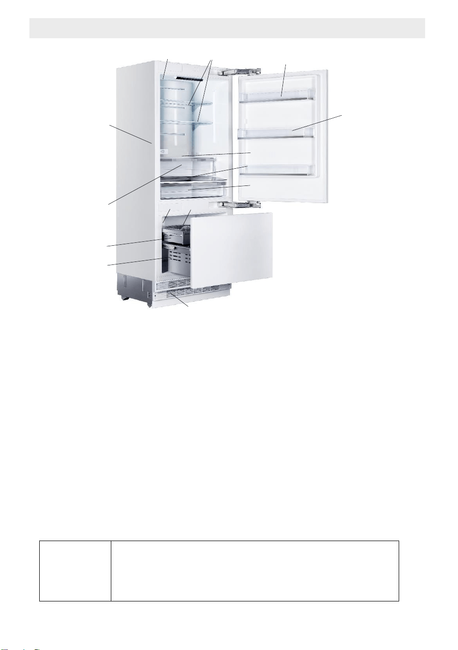
May not be available in all models
1.Water filter (if applicable)
2.Door bin
3.Body shelf (adjustable height)
4.Water dispenser
5.Gallon door bin
(adjustable height)
6.Odour filter
7.Crisper
8.Control display
9.Special temperature compartment
11.Icebox applies to high spec models
10.Ice machine (if applicable)
12.Upper drawer
13.Lower drawer
1
2
4
3
5
12
14
C
Figures in this user manual are schematic and may not
match the product exactly. If your product does not have
the relevant parts, the information applies to other
models.
2 Refrigerator Components List
7
10
6
8
9
11
13
14.Condenser
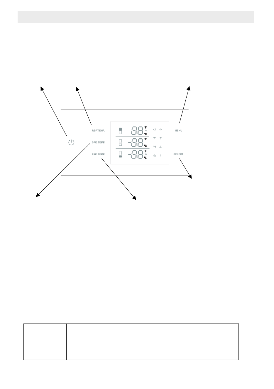
On/Off
button
Refrigerator compartment
temperature adjustment button
Special fridge compartment
temperature adjustment button
Freezer compartment temperature
adjustment button
Function election /
Child lock button
Confirm button
C
Figures in this user manual are schematic and may not
match the product exactly. If your product does not have
the relevant parts, the information applies to other
models.
May not be available in all models
3 Display Panel Set Up Instructions

1. On/Off button
Serves to switch the whole appliance On and Off. Press the button to
switch on the product, the product will be switched on in 5 seconds. Press
the on/off button for 1.5 seconds to switch off.
2. Function election / Child lock button
The child lock is a feature for preventing children from changing the product
settings. by pressing MENU button for 3 seconds, you may lock/unlock the
control panel.
The lock symbol will illuminate on the display when this function is enabled.
will
6. Holiday Mode
Press the MENU button till the holiday symbol illuminates, then press the
SELECT button to enable the function.
When the Holiday Mode function is enabled,
4. Special fridge compartment temperature adjustment button
Press the SPE TEMP button to change the special fridge compartment
temperature from -1°C(30°F ) to 5°C(41°F
3. Refrigerator compartment temperature adjustment button
Press the REF TEMP button to adjust the temperature from 2°C(36°F )
to 8°C(46°F ).
* Super fridge function will be enabled if keep pressing after 2°C(36°F ).
When the snow symbol illuminate on the display the super fridge function
will be enabled.
The best temperature for fresh food compartment is 4°C(39°).
)
5. Freezer compartment adjustment button
Press the FRE TEMP button to change the freezer compartment temperature
from -24°C(-11°F ) to -15°C(5°F)
* Super freezer function will be enabled if keep pressing after -24°C(-11°F ) .
When the snow symbol illuminate on the display the super freezer function
will be enabled.
NOTE : The defaulted temperature setting is 5°C(41°F )
for fridge compartment,2°C(36°F ) for special fridge compartment and -18°C
(0°F )for freezer compartment
the fridge temperature
be
set at 17°C(63°F ) and freezer temperature set at -18°C(0°F ),
special fridge compartment 17°C(63°F ) automatically.
NOTE: Do not place food in the fresh food compartment when Holiday Mode
is enabled.
3 Display Panel Set Up Instructions

7. Sabbath Mode
Press the MENU button till the Sabbath mode symbol illuminates, then press
the SELECT button to enable the function. When the Sabbath mode function is
enabled, all lights, buzzers, display panels will be switch off.
10. Ice Making (if applicable)
Press the MENU button till the ice making symbol illuminates,
then press the SELECT button to enable the function.
When the ice making function is enabled, ice maker will be automatically
operating, and the ice cubes will be accumulated in the ice tray.
NOTE: Prepare the water filter for use before using the ice. After connecting
the refrigerator to a water source or after replacing the water filter, fill and
discard two full containers of ice
9. Water Dispenser (if applicable)
Press the MENU button till the water dispenser symbol illuminates, then press
the SELECT button to enable the function. When the water dispensing function
is enabled, fresh water can be provided from the dispenser fitted
on the internal wall
8 Eco Mode
Press the MENU button till the Eco Mode illuminates, then press the SELECT
button to enable the function. When the Eco Mode function is enabled,
the fridge temperature will be set at 8°C(46 °F ) and freezer temperature set
at -15 °C(5 °F ),special fridge compartment 5°C(41°F ) automatically.
.
.
11. Water filter replacement (if applicable)
The water filter symbol flashes and beeps to advise the user to replace
the water filter. After the replacement is completed, press the SELECT
button for 5 seconds to reset. The set replacement time is 130 days.
12. Celsius and Fahrenheit selection
Press the MENU button till the Celsius and Fahrenheit selection symbol
illuminates to change between Celsius and Fahrenheit. After that press the
SELECT button to confirm.
3 Display Panel Set Up Instructions
4 Before Using the Refrigerator
4.1 Things to do for energy saving
• Do not leave the doors of your refrigerator open for a long time.
• Do not put hot food or drinks in your refrigerator.
• Do not overload the refrigerator. Cooling capacity will fall
when the air circulation in the refrigerator is hindered.
• Do not place the refrigerator in places subject to direct sunlight.
Install the product at least 30 cm away from heat sources such as hobs,
ovens, heater units and stoves and at least 5 cm away from electrical ovens.
• Pay attention to store your food in refrigerator in closed containers.
• You can remove the drawer shelf of the freezer compartment to fill
the freezer compartment with maximum amount of food.
The given energy consumption value of the refrigerator has been determined
with the freezer compartment shelf or the drawer removed and the refrigerator
filled with maximum amount of food.
There is no harm in using a shelf or drawer according to the shapes and
sizes of food to be frozen.
• Thawing the frozen foods in the fridge compartment both saves energy
and reserves the quality of the foods
C
Temperature of the room where your refrigerator is
located should at least be 10ºC/50°F. Operating your
refrigerator under cooler conditions is not recommended
with regard to its efficiency
C
inside of your refrigerator must be cleaned thoroughly.
C
If two coolers are to be installed side by side, there
should be at least 4 cm distance between them
4.2 Recommendations About the Fresh Food Compartment
• Make sure that the food does not touch the temperature sensor
in fresh food compartment. To allow the fresh food compartment
to keep its ideal storage temperature, the sensor must not be hindered by food.
• Do not place hot foods or beverages inside the product.
A
Connecting your refrigerator to systems that save
energy is dangerous as they may cause damage on the
product.

4 Before Using the Refrigerator
4.3 Initial use
Before using the product, make sure that all preparations have been made
in accordance with the instructions given in the "Important instructions
regarding safety and environment" and "Installation Instruction" chapters.
• Clean the interior of the refrigerator as recommended in the “Maintenance
and cleaning” section. Before you start the refrigerator, make sure
that the interior is dry.
• Plug the refrigerator in a grounded socket. The interior illumination is lit
when the door of the refrigerator is opened.
• Operate the refrigerator for 6 hours without placing any food in it and
do not open its door unless it is necessary
C
You will hear a noise when the compressor starts up.
The liquids and gases sealed within the refrigeration
system may also give rise to noise, even if the
compressor is not running and this is quite normal.
C
Front edges of the refrigerator may feel warm.
This is normal.
These areas are designed to be warm
to avoid condensation.

5 Operating the product
5.1 Dual Cooling System
Your refrigerator is equipped with two separate cooling systems
to cool the fresh food compartment and freezer compartment.
Thus, the air and odor in the fresh food compartment and
the frozen food compartment do not get mixed.
Thanks to these two separate cooling systems, cooling speed is much higher
than that of other refrigerators. Also additional power saving is provided
since the defrosting is performed separately.
5.2 Freezing Fresh Food
Wrap the foods or place them in a covered container before putting them
in the refrigerator.
• Hot foods and beverages must cool down to the room temperature
before you put them in the refrigerator.
• The foodstuff that you want to freeze must be fresh and in good quality.
• Divided the food into portions according to your family's daily or
meal based consumption needs.
• Pack the foods in an airtight manner to prevent them from drying even if
they are going to be stored for a short time.
• Materials to be used for packaging must be tear-proof and resistant
to cold, humidity, odor, oils and acids and they must also be airtight.
Moreover, they must be well closed and they must be made
from easy-to-use materials that are suitable for deep-freezers.
• Frozen food must be used immediately after they are thawed
and they should never be refrozen.
• Do not freeze too large quantities of food at one time.
The quality of the food is best preserved when it is frozen right through
to the core as quickly as possible.
• Placing warm food into the freezer compartment causes the cooling system
to operate continuously until the food is frozen solid.
5.3 Recommendations for Storing Frozen Food
• Frozen foods you purchase must be stored according to the conditions and
temperature determined by the food manufacturer.
• Note the following to ensure that the high quality achieved
by the frozen food manufacturer and the food retailer is maintained:
1. Put packages in the freezer as quickly as possible after purchase.
2. Make sure that the content of the package is labeled and dated.
3. Check whether the "Use By" or "Best Before" date
on the packaging is expired or not.
5 Operating the product
5.4 Placing the food
Freezer compartment
shelves
Various frozen food such as meat, fish,
ice cream, vegetables etc.
Egg tray Eggs
Fridge compartment
shelves
Food in pans, covered plates and closed
containers
Door shelves of fridge
compartment
Small and packaged foods or beverages
(such as milk, fruit juice, beer and etc.)
Crisper Vegetables and fruits
Special fridge
compartment
Delicatessen products
(cheese, butter, salami etc.)
Freezer Fridge
Remarks
-18°C / 0°F 4°C / 39°F
This is the recommended normal setting.
-20°C / -4°F 3°C / 37°F
These settings are recommended
when the ambient temperature is
above 30°C/86°F.
4°C / 39°Super Freezer F
Use when you wish to freeze your food in a
short time. Your refrigerator will return to
its previous mode when the process is
over.
-24°C / -12°F
Use these settings if you think that your
fridge compartment is not cold enough
because of the hot ambient conditions or
2°C / 36°F
frequent opening and closing of the door.
Use this function when you place too much
into the fridge compartment or when you
need to cool your food quickly. It is
recommended that you activate Quick
Fridge function 4-8 hours before placing the
-18°C / 0°F or
colder
Super Fridge
food
Recommended Operating Temperature:
Fridge: 4°C / 39°F , Freezer: - 18°C / 0°F
5.5 Operating temperature
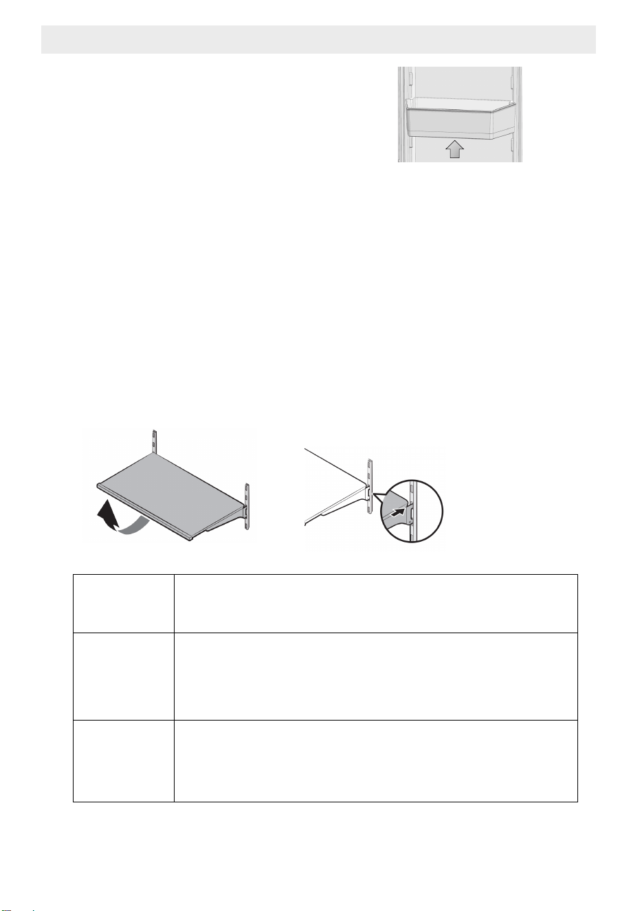
5 Operating the product
5.6 Door bin
To remove, lift up the door bin
and then pull out straight.
5.7 Glass shelves
To remove a shelf
- Fully open the corresponding door.
- Hold the front of the shelf, and then gently lift up and slide out.
To reinsert
- hold the shelf at an angle so the front is higher than the back,
and then insert the top hook into the top shelf notch.
- Put down the front slightly.
IMPORTANT NOTE:
Use care when handling glass shelves
to prevent breakage or scratching the interior.
A
ATTENTION:
Glass shelves must be unloaded.
A
ATTENTION:
You must wait for the glass shelves
to reach room temperature before immersing
them in water for cleaning.
A
ATTENTION:
The door may not be closed if the door shelves are
positioned at the same level as glass shelves. Make
sure than the door is closed after placing the shelves.
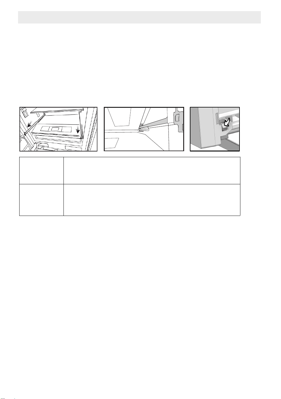
5 Operating the product
5.8 Crisper compartment
To remove the crisper
- Pull the crisper until it stops.
- Slightly unclip the front section of the drawer and take it out completely.
To install the crisper
- Pull the rails completely.
- Place the gap at the rear corners of the crisper to the detail located
at the rear corners of the rails.
- Push the crisper slowly down until you feel it clip front onto the rails.
C
Make sure that the details at the right and left-hand
sides are fixed when installing the crisper.
C
Never leave the vegetables in their plastic bags in the
crisper. If they are left in their plastic bags they will rot
in a short period of time.
The crisper compartment preserves the humidity of your vegetables,
allowing you to store them for a long time without having to keep
them in their bags.
If you do not prefer the vegetables to get into contact with other vegetables
due to hygienic reasons, you can use perforated paper, foam or a similar
material instead of plastic bags.
While the vegetables are being replaced, their specific weights should be
taken into consideration.
Heavy and hard vegetables must be placed at the bottom of the crisper
and light and soft vegetables must be on the upper part.
Pears, kiwis, tomatoes, cucumbers, apricots, peaches, broccolis, lettuces,
cabbages, parsley and spinach are fruits and vegetables
that emit ethylene gas.
Do not place them into the same crisper with other fruits and vegetables.
The ethylene gas emitted by these foods cause other fruits and vegetables to
ripen sooner and to rot in a shorter span of time.
Do not remove the main body of the crisper from the refrigerator separately
unless you have to do so.
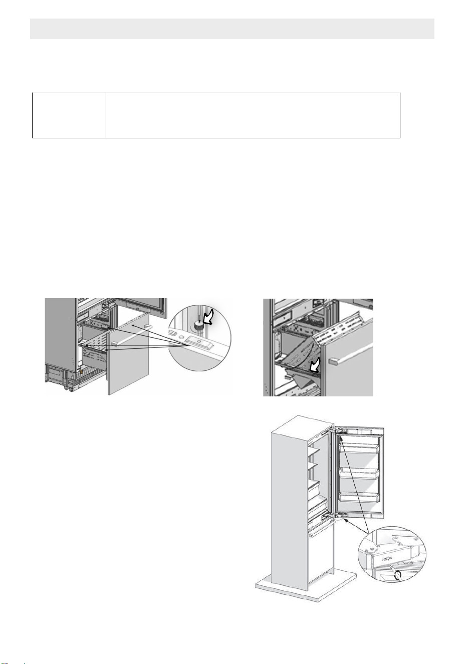
5 Operating the product
5.9 Special fridge compartment
You can control the temperature in this section to store your food
such as fish, meat, vegetables and delicatessen products for a longtime.
C
Removal/installation procedures of the special fridge
compartment are same as that of the crisper.
5.10 Freezer Crisper
The freezer compartment store your foods at a temperature
between -24°C and -18°C to keep them fresh for a long time.
To remove the crisper
- Open the freezer door until it stops.
- Unscrew drawer fixing screw and take it out carefully..
To install the crisper
- Open the freezer door until it stops.
- The crisper slowly down and screw drawer fixing bolt.
5.11 Hinge Adjustment
When adjusting the hardness of
the hinge: Hardness of the
lower and upper door hinges of
the fresh food compartment is
performed with the help of a
drill. Set the hinge adjustment
screw to position "1" from
position "0".
5.12 Changing the Direction of the Door
Please see the installation instructions provided
in the bag.

6 Care and Cleaning
Service life of the product will extend and frequently encountered problems will
decrease if the product is cleaned periodically.
Never use gasoline, benzene or similar substances for cleaning purposes.
Never use any sharp abrasive instruments, soap, household cleaners,
detergent or wax polish for cleaning.
Dissolve one teaspoon of carbonate in half liter of water Soak a cloth in the
solution and wring it thoroughly. Wipe the interior of the refrigerator with this
cloth and the dry thoroughly.
Make sure that no water enters the lamp housing or other electrical parts.
If you will not use the refrigerator for a long time, unplug it, remove all food
inside, clean it and leave the door ajar.
Check regularly that the door gaskets are clean. If not, clean them.
Take out all items in the product to remove the door and body shelves.
Remove the door shelves by pulling them up. Slide the shelves downwards to
re-install them after cleaning.
Never use chloric cleaning agents or water to clean outer surfaces or chrome-
coated parts of the product. Chlorine causes abrasion on such metal surfaces.
6.1 Avoiding Bad Odors
Materials that may cause odor are not used in the production of our
refrigerators. However, odor may be emitted if foods are stored improperly or
if the inner surface of the product is not cleaned as required.
Please consider the following to avoid this problem:
It is important that the refrigerator is kept clean.
Food residuals, stains, etc. can cause odor.
For this reason, clean your refrigerator with carbonate solved
in water every 15 days. Never use detergents or soap.
Keep your foods in closed vessels. Microorganisms emitted from vessels
without a cover may cause unpleasant odors.
Never keep expired or spoiled foods in your refrigerator.
6.2. Protecting the Plastic Surfaces
Do not put liquid oils or oil-cooked meals in your refrigerator in unsealed
containers as they damage the plastic surfaces of your refrigerator.
If oil is spilled or smeared onto the plastic surfaces, clean and
rinse the relevant part of the surface with warm water immediately.
B
WARNING Switch off the product before cleaning.
B
WARNING It is recommended to clean
the condenser every six months using gloves.
You must not use vacuum cleaners.

6 Care and Cleaning
6.3 Cleaning the Inner Surface
To clean the inner surfaces and all removable parts,
wash them with a mild solution comprising soap, water and carbonate.
Rinse and dry thoroughly.
Prevent the water from contacting the lighting means and control panel.
6.4 Stainless Steel Outer Surfaces
Use a stainless steel cleaning agent that is non- abrasive and
apply it with a lint-free, soft cloth.
For polishing, wipe the surface softly with a damp microfiber cloth
and use dry wash-leather.
Always follow the strands of the stainless steel.
A
ATTENTION:
Do not use vinegar, rubbing alcohol or other
alcohol-based cleaning agents
on any of the inner surfaces.

7 Trouble Shooting
Please review this list before calling the service.
This will save you time and money.
This list contains frequently encountered problems that are not results
of faulty workmanship or material use.
Your product may not have some of the features described here.
The refrigerator is not operating.
• It may not be plugged in properly. >>> Plug in the product properly.
• The fuse of the socket to which your refrigerator is connected
or the main fuse may have blown.
>>>Check the fuse.
The condensation on the fridge compartment
• The door may have been opened/closed frequently.
>>>Do not open/close the refrigerator door frequently.
• The environment may be too humid.
>>>Do not install the refrigerator at locations with a very high
level of humidity.
• Foods containing liquid may have been placed into the refrigerator
in vessels without covers.
>>> Do not place foods containing liquid into the refrigerator
in unsealed vessels.
• Door of the refrigerator may have been left ajar.
>>>Do not keep the doors of your refrigerator open for a long time.
The compressor is not operating.
• Protective thermal of the compressor will blow out during sudden power
failures or plug-out plug- ins as the refrigerant pressure in the cooling system
of the refrigerator has not been balanced yet.
• The refrigerator will start running approximately after 6 minutes.
Please call the Authorised Service Provider if the refrigerator does
not start at the end of this period.
• The freezer is in defrosting cycle. >>>This is normal for a refrigerator
that performs full-automatic defrosting.
Defrosting cycle is performed periodically.
• The refrigerator may not be plugged in.
>>>Make sure that the plug fits the socket.
• Temperature settings may be incorrect.
>>>Select the correct temperature value.
• Possible power failure.
>>>The refrigerator will start to operate normally when power restores.

7 Trouble Shooting
The operation noise increases when the refrigerator is running.
Operating performance of the refrigerator may vary based
on the ambient temperature changes.
This is normal and not a fault.
Vibration or noise.
• The floor may not be stable or level.
>>>If the refrigerator shakes when moved slightly feed to balance it.
Make sure that the floor is level and capable of carrying the refrigerator.
• Objects placed onto the refrigerator may cause noise.
>>>Remove the objects on the refrigerator.
There are noises coming from the refrigerator like liquid
spilling or spraying.
• Liquid and gas flows occur in accordance with the operating principles
of the refrigerator. This is normal and not a fault.
Whistle is heard from the refrigerator.
• There are fans that are used to cool the refrigerator.
This is normal and not a fault.
Damp accumulates on the inner walls of refrigerator.
• Hot and humid weather increases icing and condensation.
This is normal and not a fault.
• The doors may have been opened frequently or left ajar
for a long time.
>>>Do not open the door frequently. Close the doors, if open.
• The door may have been left ajar.
>>>Close the door completely.
Humidity occurs on the outer surface of the refrigerator or
between the doors.
• Air might be humid. This is quite normal in humid weathers.
>>>Condensation will disappear the humidity level decreases.
• There might be external condensation at the section between
two doors of the refrigerator if you use your product rarely.
This is normal. Condensation will disappear upon frequent use.

7 Trouble Shooting
There is a bad odour inside the refrigerator.
• No regular cleaning may have been performed.
>>>Clean the inside of the refrigerator sponge, lukewarm water
or carbonated water.
• Some vessels or packaging materials may cause the odour.
>>>Use another vessel, or packaging materials from another brand.
• Foods may have been placed into the refrigerator in vessels
without covers. >>>Store the foods in closed vessels.
Microorganisms emitted from vessels without a cover may cause
unpleasant odors.
• Take out expired or spoiled foods from the refrigerator.
The door cannot be closed.
• Food packages may be preventing the door from closing.
>>> Re-locate the packages obstructing the door.
• The refrigerator may be unstable on the floor.
>>>Adjust the refrigerator feet as requir the refrigerator in balance.
• The floor may not be level or solid.
>>>Make sure that the floor is level and capable of carrying
the refrigerator.
Crispers are stuck.
• Foods may be touching the upper wall of the crisper.
>>>Re-organise the foods in the crisper.
A
WARNING
If you can not eliminate the problem although
you follow the instructions in this section,
consult your dealer or the Authorized Service Provider.
Never attempt to repair a malfunctioned product.

DISCLAIMER
Worldwide Appliances PTY LTD, trading as ARTUSI, is continually seeking ways to improve the design specications, aesthetics and production
techniques of its products. As a result alterations to our products and designs take place continually. Whilst every eort is made to produce
information and literature that is up to date, this brochure should not be regarded as an infallible guide to the current specications, nor does
it constitute an oer for the sale of any particular product. Product dimensions indicated in our literature is indicative only. Actual product only
should be used to dene dimension cutouts. Distributors, and retailers are not agents of ARTUSI and are not authorised to bind ARTUSI by any
express or implied undertaking or representation.
artusi.com.au
NSW & ACT (Head Ofce)
48-50 Moore Street
Leichhardt
F 02 8569 4699
Victoria
2r/131 Church Street
Hawthorn
QLD
Contact Head Ofce
WA & NT
Unit 10/55 Howe Street
Osborne Park
Australia National Telephone Number 1300 694 583
Our showrooms are open daily from 9am-5pm and Saturdays 10am-4pm
/artusi_kitchen_laundry_outdoor