1. Packing List 3. LED Patterns
4. Wiring Instructions
5. Installation Preparations
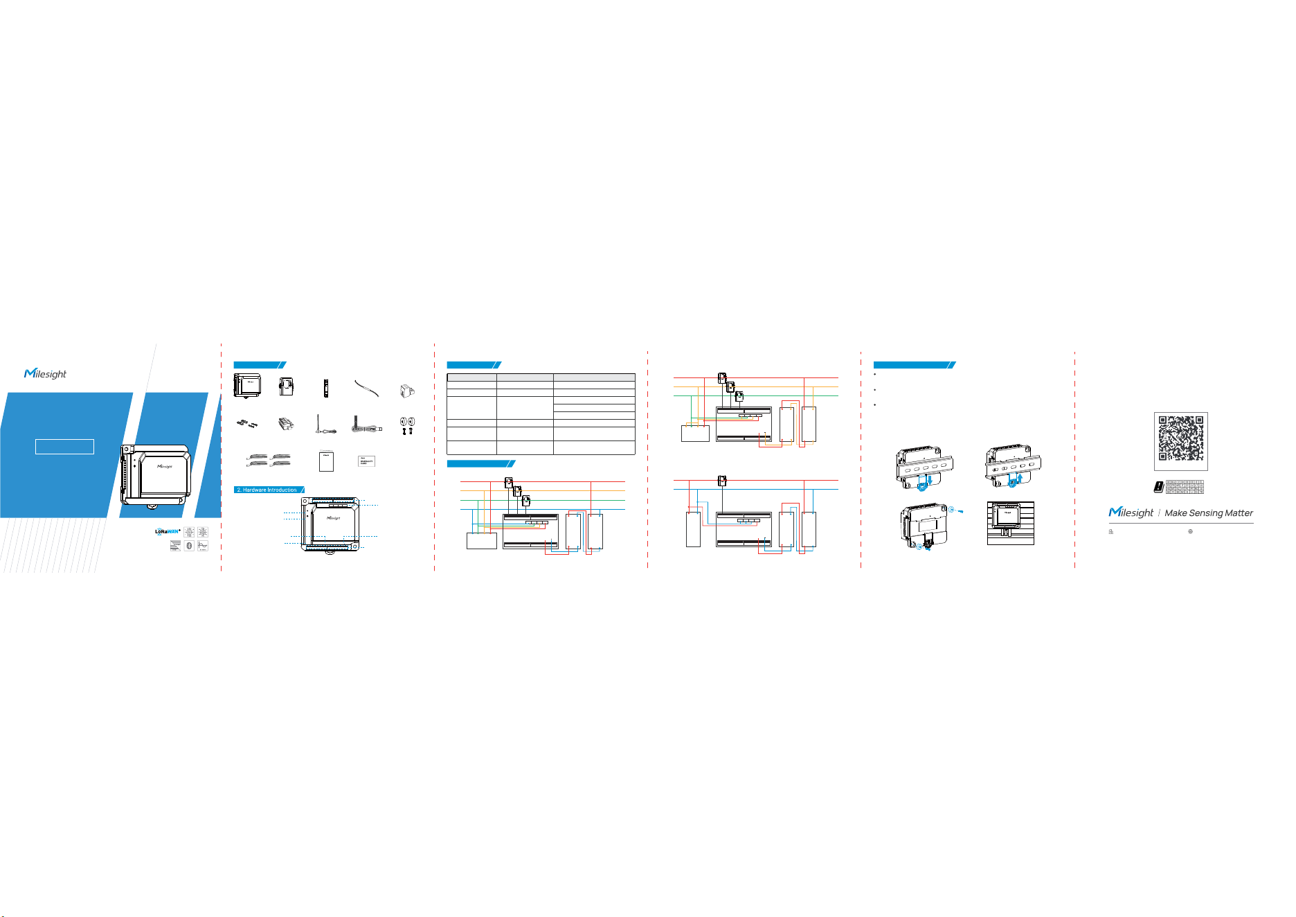
QUICK START GUIDE
Smart Power Monitor Hub
Quick Start Guide
Milesight IoT Co., Ltd. www.milesight.com
Warranty Card
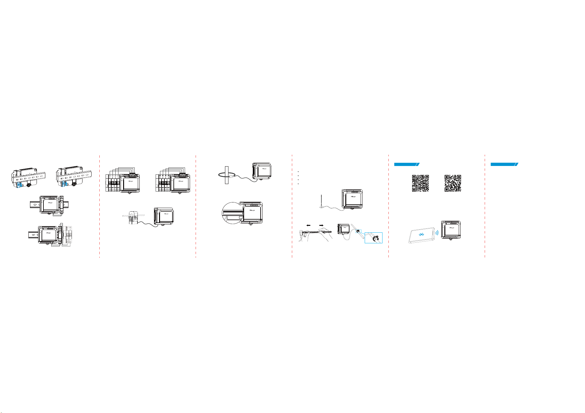
Device Installation
Step 1:
Note: The width of the DIN rail is 3.5 cm.
LoRaWAN
Magnetic Antenna
USB-C
NTC Sensor
Magnetic
Nuts (Optional)
CTH01
Main Unit
Current
Transformer
Mounting
Screw Kits
Voltage
Terminal Block
Power
Terminal Block
Magnetic Voltage
Measuring Cable (Optional)
Power
Adapter
Power
Terminal Wire
Quick
Start Guide
Type-C USB Interface
Reset Button
Power Indicator
12VDC
+
Type-C
LoRa
POWER
RESET
NL3
L2
L1
Group d
12
11
10
Group c
9
87
Group a
12
3
Group b
4
5
6
LoRaWAN Magnetic
Antenna Interface
Power Interface
Voltage Channels
Current Channels (Group a/b)
Current Channels(Group c/d)
De-activated:
Stays On
Sending Join Request:
Blinks Quickly Once
The collected parameters
exceeded the set threshold
Press and hold the reset
button for more than 10s
Activated Successfully:
Blinks Slowly Once
Stays On
Blinks Quickly
Quickly Blinks
LoRaWAN Status
Operational Status
Threshold Alarm
Reset to Factory
Default
Operation
Indicator
Function
On
Power On The power is switched on
Off
Power Off
The power is switched off
бThree-Phase Four-Wire
вThree-Phase Three-Wire
гSingle-Phase Two-Wire (L-N)
12 V D C
+
NL3
L2
L1
Group d
12
11
10
Group c
9
87
Group a
12
3
Group b
4
5
6
1
/
/
/
Circuit Breaker
1///
1///
Circuit
Breaker
1/
1/
Power
Adapter
Circuit Breaker
Circuit
Breaker
1/
1/
Circuit
Breaker
1/
1/
Circuit
Breaker
1/
1/
Power
Adapter
Power
Adapter
1/
12 V D C
+
NL3
L2
L1
Group d
12
11
10
Group c
9
87
Group a
12
3
Group b
4
5
6
/
/
/
1///
1///
1/
12 V D C
+
NL3
L2
L1
Group d
12
11
10
Group c
9
87
Group a
12
3
Group b
4
5
6
1
/
1/
Only qualified professional electricians are allowed to install this device. High voltage may be
present and can be life-threatening!
The main power supply of the target distribution box or circuit must be cut off. After power-off,
wait for at least 5 minutes to to ensure the circuit capacitors are fully discharged!
Use insulated tools and wear insulating gloves throughout the process, and strictly comply
with local electrical safety regulations.
DIN Rail Mounting
Magnetic Nuts Mounting
12VD C
+
Type-C
LoRa
POWER
RESET
NL3
L2
L1
Group d
12
11
10
Group c
9
87
Group a
12
3
Group b
45
6
®
®
®
Power:
BLE: 7.18dBm
Lora: 7.65 dBm
Frequency (TX and RX)
BLE: 2402-2480MHz
Lora: 863-868MHz
Add: Building C09, Software Park Phase III, Xiamen 361024, Fujian, China
CTH01-868M/915M
CE
6. Configuration
7. FCC Statement
Any changes or modifications not expressly approved by the party responsible for compliance
could void the user’s authority to operate the equipment. This device complies with part 15 of
the FCC Rules. Operation is subject to the following two conditions:
(1) This device may not cause harmful interference, and.
(2) This device must accept any interference received, including interference that may cause
undesired operation.
Note: This equipment has been tested and found to comply with the limits for a Class B digital
device, pursuant to part 15 of the FCC Rules. These limits aredesigned to provide reasonable
protection against harmful interference in a residential installation. This equipment generates,
uses and can radiate radio frequency energy and, if not installed and used in accordance with
the instructions, may cause harmful interference to radio communications. However, there is
no guarantee that interference will not occur in a particular installation. If this equipment does
cause harmful interference to radio or television reception, which can be determined by
turning the equipment off and on, the user is encouraged to try to correct the interference by
one or more of the following measures:
—Reorient or relocate the receiving antenna.
—Increase the separation between the equipment and receiver.
—Connect the equipment into an outlet on a circuit different from that to which
the receiver is connected.
—Consult the dealer or an experienced radio/TV technician for help.
FCC Radiation Exposure Statement:
This equipment complies with FCC radiation exposure limits set forth for an uncontrolled
environment. This equipment should be installed and operated with minimum distance 20cm
between the radiator& your body. This transmitter must not be co-located or operating in
conjunction with any other antenna or transmitter.
1. Download and install “Milesight ToolBox” App on an a Bluetooth-enabled smartphone.
2. Enable Bluetooth and location function on the smart phone.
3. Open “Milesight ToolBox” App, select Bluetooth method and search for the target device to
connect, and then enter the Bluetooth password to read/write the device until App shows a
WYGGIWWJYPTVSQTX8LIɸHIJEYPXɸ&PYIXSSXLɸREQIɸMWɸ'8,<<<<<<<XLɸXSɸWXɸGLEVEGXIVWSJ
HIZMGIɸ72ɸERHXLIɸHIJEYPXɸPSKMRɸTEWW[SVHɸMWɸ-XƅWWYKKIWXIHXSGSRJMKYVIEHIZMGI
password for security.
Step 2:
12V D C
+
Type-C
LoRa
POWER
RESET
NL3
L2
L1
Group d
12
11
10
Group c
9
87
Group a
12
3
Group b
4
5
6
,QSXW9
2XWSXW9
12V D C
+
Type-C
LoRa
POWER
RESET
NL3
L2
L1
Group d
12
11
10
Group c
9
87
Group a
12
3
Group b
45
6
1
1
99
99
Step 3:
Step 4:
Voltage Terminal Block Connection
Connect Current Transformer
Connect Rogowski Coils
or
Magnetic Voltage Measuring
Cable Connection
1
1
12VDC
+
Type-C
LoRa
POWER
RESET
NL3
L2
L1
Group d
12
11
10
Group c
9
87
Group a
12
3
Group b
4
5
6
1
1
12VDC
+
Type-C
LoRa
POWER
RESET
NL3
L2
L1
Group d
12
11
10
Group c
9
87
Group a
12
3
Group b
4
5
6
Note: If measuring a three-phase circuit, please use three channels of the same group.
12V DC
+
Type-C
LoRa
POWER
RESET
NL3
L2
L1
Group d
12
11
10
Group c
9
87
Group a
12
3
Group b
45
6
N
Group a
12
3
Note: If a Rogowski Coil is used for one channel, the other two channels in the same group must
also use Rogowski Coils.
Antenna Installation
USB-C NTC Sensor Installation
Note:
The antenna should be installed vertically, with the magnetic base attached to a metal surface.
Keep the antennas away from walls and ensure there are no obstacles around them.
For better coverage, it is recommended to position the antennas at a higher location.
Place the antennas near windows when used indoors.
12V DC
+
Type-C
LoRa
POWER
RESET
NL3
L2
L1
Group d
12
11
10
Group c
9
87
Group a
12
3
Group b
4
5
6
iOSAndroid
12V D C
+
Type-C
LoRa
POWER
RESET
NL3
L2
L1
Group d
12
11
10
Group c
9
87
Group a
12
3
Group b
4
5
6