EN
Original Instructions
Version 3 - February 2025
83811/84121
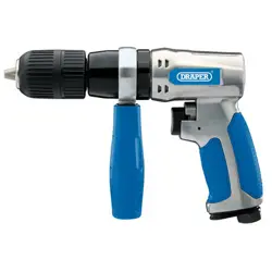
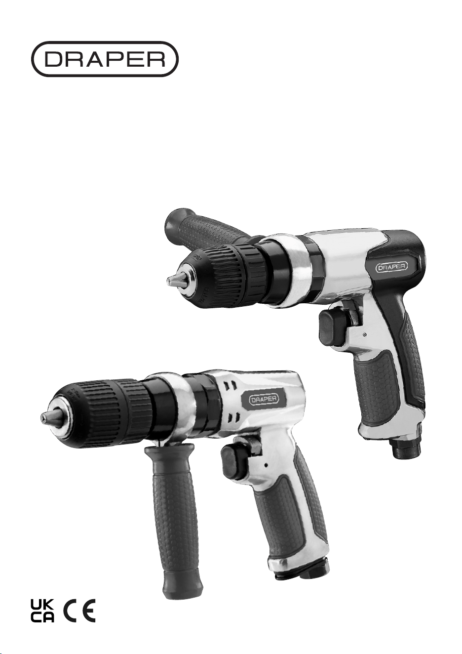
AIR
DRILL
Stock No: 84121
Stock No: 83811
1.1 Product Reference
User Manual for: Air Drill
Stock No: 83811/84121]
Part No: DAT-RAD10, DAT-RAD-13
1.2 Revisions
Version 1: October 2017
First release
Version 2: July 2021
Version 3: February 2025
As our manuals are continually updated, always ensure
that the latest version is used.
Please visit drapertools.com/manuals for the latest
version of this manual and the associated parts list, if
applicable.
1.3 Understanding the Safety Content of
This Manual
WARNING! – Situations or actions that may result
in personal injury or death.
CAUTION! – Situations or actions that may result
in damage to the product or surroundings.
Important: – Information or instructions of particular
importance.
1.4 Copyright © Notice
Copyright © Draper Tools Limited.
Permission is granted to reproduce this manual for
personal and educational use ONLY. Commercial
copying, redistribution, hiring or lending is strictly
prohibited.
No part of this manual may be stored in a retrieval system
or transmitted in any other form or means without written
permission from Draper Tools Limited.
In all cases, this copyright notice must remain intact.
1. Preface
– 2 –
These are the original product instructions. This
document is part of the product; retain it for the life
of the product, passing it on to subsequent holders.
Read this manual in full before attempting to
assemble, operate or maintain this product.
This Draper Tools manual describes the purpose
of the product and contains all the necessary
information to ensure its correct and safe use.
Following all the instructions and guidance in
this manual will ensure the safety of both the
product and the operator and increase the
lifespan of the product.
All photographs and drawings within this manual are
supplied by Draper Tools to help illustrate correct
operation of the product.
Every eort has been made to ensure the
information contained in this manual is accurate.
However, Draper Tools reserves the right to amend
this document without prior warning. Always use the
latest version of the product manual.

2. Contents
– 3 –
EN
1. Preface 2
1.1 Product Reference 2
1.2 Revisions 2
1.3 Understanding the Safety Content of
This Manual 2
1.4 Copyright © Notice 2
2. Contents 3
3. Product Introduction 4
3.1 Intended Use 4
3.2 Specication 4
4. Health and Safety Information 5-6
4.1 General Health and Safety Precautions 5
4.2 Additional Safety instructions for
Compressed Air 5
4.3 Additional Safety Instructions for Air Drills 5
4.4 Residual Risk 6
5. Identication and Unpacking 7
5.1 Product Overview 7
5.2 Packaging 7
6. Assembly Instructions 8
6.1 Preparing the Air Supply for Use 8
6.2 Connection To The Air Supply 8
7. Operating Instructions 9-10
7.1 Keyless Chuck 9
7.2 Trigger Switch 9
7.3 Directional control Switch 9
7.4 Using the Drill 10
8. Maintenance Storage and Disposal 10
9. Troubleshooting 11
10. Warranty 12
11. Explanation of Symbols 13

– 4 –
3. Product Introduction
3.1 Intended Use
This reversible air drill features a quick-change keyless
chuck for fast bit changes and suitable for drill bits with
diameters up to 10mm (83811) and 13mm (84121).
Any other application beyond the conditions established
for use will be considered misuse. Draper Tools accepts
no responsibility for improper use of this product.
Read this manual in full before attempting to assemble,
operate or maintain the product, and retain it for later use.
Important: The declared vibration total values and noise
emissions values have been measured in accordance
with a standard test method and may be used for
comparing one tool with another. These values may also
be used in a preliminary assessment of exposure.
WARNING! The vibration and noise emissions
during actual use of the product can dier from
the declared values depending on the type of
work and the area upon which it is used. Before
each use, estimate the likely exposure resulting
from the actual conditions of use. Take into
account all parts of the operation cycle in order
to identify any safety measures required to
protect the operator.
3.2 Specication
Stock No. 83811 84121
Part No. DAT-RAD10 DAT-RAD13
Chuck Size: 10mm (3/8”) 13mm (½“)
Max. Operating Air Pressure: 90psi (6.2bar) 90psi (6.2bar)
Average Air Consumption: 155L/min (5.5cfm) 184L/min (6.5cfm)
Speed (no load): 2200rpm 700rpm
Minimum Air Line size: 3/8” ID 3/8”ID
Air Inlet: ¼ “ BSP ¼ “ BSP
Noise emissions:
Sound pressure level: 87dB (A) 87dB (A)
Sound power level: 98dB (A) 98dB (A)
Vibration level: 1.0m/s
2
1.0m/s
2
Net Weight: 1.48kg 1.66kg
EN

– 5 –
4. Health and Safety Information
EN
Important: Read all the Health and Safety instructions
before attempting to operate, change accessories,
maintain or repair this product. Failure to follow these
instructions may result in injury or damage to the user,
the product or the workpiece.
4.1 General Health and Safety Precautions
• Only qualied and trained operators should use or
adjust the air drill.
• DO NOT modify this drill. Modications can reduce
the eectiveness of safety measures and increase the
risks to the operator.
• Retain the safety instructions for future reference and
use by the operator.
• DO NOT use the drill if it has been damaged.
• Inspect the tool periodically to verify that the ratings
and markings required are attached and legible.
• Keep bystanders away during operation.
• ALWAYS wear appropriate personal protective
equipment (PPE). Personal protective safety glasses
and dust mask shall be used; suitable gloves and
protective clothing are recommended.
• Have your tool serviced by a qualied repair person
using only identical replacement parts.
4.2 Additional Safety instructions for
Compressed Air
WARNING! Compressed air can cause severe injury.
− ALWAYS turn o and disconnect the air supply
before making any adjustments to the product or
leaving it unattended.
− NEVER direct this product towards yourself or others.
− Ensure that compressed air is not blocked by or in
contact with any part of your body.
• ONLY use clean, dry and regulated compressed air.
WARNING! NEVER use oxygen, combustible
gases or other bottled gases as a supply for this
product. Use of these substances may cause the
product to explode.
• The use of a whip hose between the tool and the air
supply to reduce vibration is recommended.
WARNING! Whipping hoses can cause severe
injury. Always check for and replace damaged or
loose hoses and ttings.
• Ensure that the product is compatible with the air
supply before use.
• Ensure all connections are securely tightened.
• Where universal twist couplings (claw couplings) are
used, lock pins must be installed and whip check
safety cables must be used to safeguard against
possible hose-to-tool or hose-to-hose failure
• DO NOT exceed the maximum stated air pressure.
• DO NOT obstruct the ability of the trigger to release
once depressed.
• NEVER carry the tool by the air line.
4.3 Additional Safety Instructions for
Air Drills
• Be aware that the failure of the workpiece, or
accessories, or even of the inserted tool itself can
generate high-velocity projectiles.
• Always wear impact-resistant eye protection during
the operation of the drill. The grade of protection
required should be assessed for each use.
• Ensure that the workpiece is securely xed.
• There is a risk of crushing by torque between the drill
and the workpiece.
• Keep hands, loose clothing, hair etc. away from the
rotating spindle of the drill and accessories.
• Wear suitable gloves to protect hands.
• Hold the tool correctly; be ready to counteract normal
or sudden movements and have both hands available.
• It is recommended to use the side handle.
• High-reaction torque can be developed in the case of
stalling, which can be caused by excessive loads
being applied to the drill bit, by the drill bit snagging
on the material being drilled into or by the drill bit
breaking through the material being drilled.
• Keep hands away from the rotating chuck and drill bit.
• When using a drill to perform work-related activities,
the operator can experience discomfort in the hands,
arms, shoulders, neck or other parts of the body.
• While using a drill, the operator should adopt a
comfortable posture while maintaining a secure
footing and avoiding awkward or o-balanced
postures. The operator should change posture during
extended tasks, which can help avoid discomfort and
fatigue.
• Direct the exhaust so as to minimize disturbance of
dust in a dust-lled environment.

– 6 –
4. Health and Safety Information
EN
• Where dust or fumes are created, the priority shall be
to control them at the point of emission to avoid a
hazard.
• Release the start and stop device in the case of an
interruption of the energy supply.
• Only use lubricants recommended by the
manufacturer.
• Disconnect the tool from the energy supply before
changing the inserted tool or accessory.
• Use only sizes and types of accessories and
consumables that are recommended by the tool
manufacturer.
• Avoid direct contact with the inserted tool during and
after use, as it can be hot or sharp.
• The drill is not intended for use in potentially
explosive atmospheres and is not insulated against
coming into contact with electric power. Ensure there
are no electrical cables, gas pipes, etc., that can
cause a hazard if damaged by use of the tool.
• Noise Hazards
− Exposure to high noise levels can cause
permanent hearing loss and other problems.
Perform a risk assessment and implement any
appropriate controls for identied hazards before
performing any operation.
− Use appropriate hearing protection in accordance
with local occupational health and safety
regulations.
− Operate and maintain the tool appropriately to
prevent unnecessary increase in noise emissions.
• Vibration Hazards
− Exposure to vibration can cause disabling damage to
the nerves and blood supply of the hands and arms.
− Wear warm clothing when working in cold
conditions and keep your hands warm and dry.
− If you experience numbness, tingling, pain or
whitening of the skin in your ngers or hands,
stop using the tool and consult a qualied health
professional.
− Operate and maintain the tool appropriately to
prevent unnecessary increase in vibration
emissions.
− The risks from vibration hazards are increased
when grip force on the tool is higher. − Hold the
tool with a light but safe grip, keeping in mind that
your grip may need to be altered to react to
unexpected forces.
4.4 Residual Risk
The safety instructions in this manual cannot account for all
possible conditions and situations that may occur. Exercise
common sense and caution when using this product and
protect against any additional conceivable risks.
– 7 –
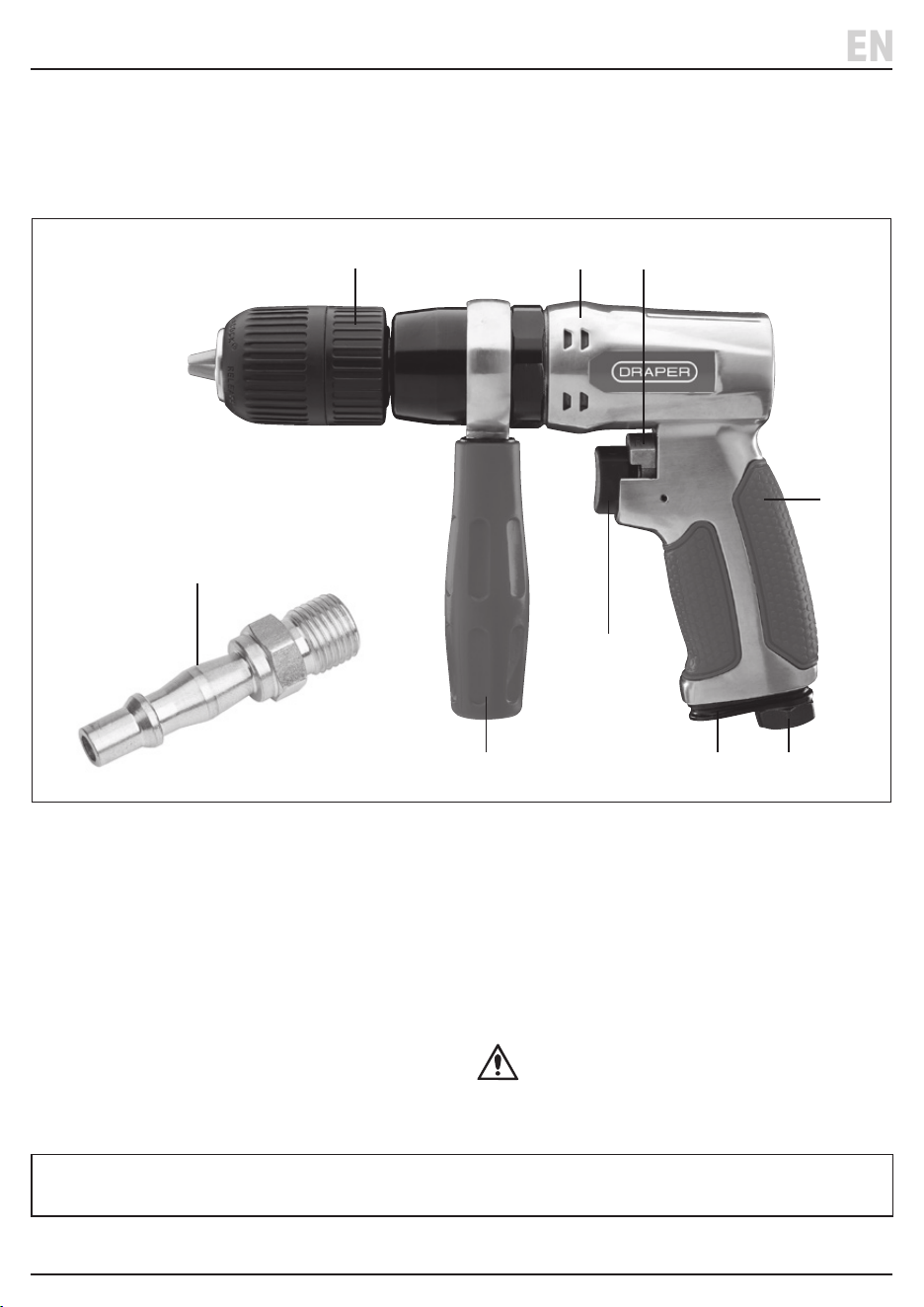
5. Identication and Unpacking
5.1 Product Overview
(1) Keyless chuck
(2) Aluminium body
(3) Forward and reverse switch
(4) Low vibration soft grip handle
(5) Female air inlet (1/4“ BSP)
(6) Air exhaust
(7) Trigger switch
(8) Side Handle
(9) Air line coupling screw adaptor
Carefully remove the product from the packaging and
examine it for any signs of damage that may have
occurred during shipment. If any part is damaged or
missing, do not attempt to use the product. Please
contact the Draper Helpline; contact details can be
found at the back of this manual.
EN
(1)
(2) (3)
(4)
(8)
(7)
(6) (5)
5.2 Packaging
Keep the product packaging for the duration of the
warranty period in case the product needs to be returned
for repair.
WARNING! Keep packaging materials out of
reach of children. Dispose of packaging
correctly and responsibly and in accordance
with local regulations.
Please visit drapertools.com for our full range of accessories and consumables.
(9)
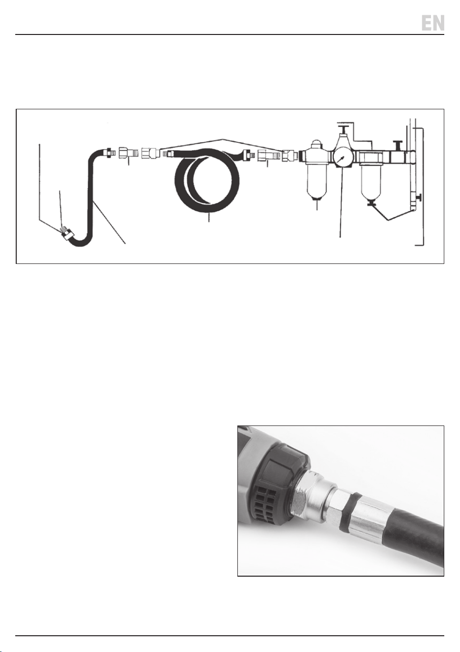
Do not install quick
coupling here.
To your
air tool
Whip hose
Nipple Nipple
Quick coupler
Air line hose
Oiler
Regulator
Drain daily
Air supply
Water separation
Fig. 1
– 8 –
6.2 Connection To The Air Supply (Fig.2)
Important: Use of a 1/4” BSP male-threaded thread whip
hose (not supplied) is recommended to connect the tool
to the air line in order to reduce vibration.
1. Wrap a length of PTFE tape around the thread before
securing the hose in place.
2. Check that the connection is secure and airtight.
6. Assembly Instructions
EN
6.1 Preparing the Air Supply for Use (Fig.1)
Important: Before preparing or adjusting this product,
read and understand all the safety instructions listed in
this manual.
Important: Always disconnect from the air supply before
assembling, carrying out adjustments, servicing or
maintenance.
Fig. 2
• This air tool operates at a max. pressure of 6.2bar
(90psi).
• The compressed air system must be controlled by a
combination pressure regulator, in-line lubricator and
moisture lter. This will ensure a constant supply of
dry air at all times, provided it is properly maintained.
• Important: Always check the machine operating
pressure before use.
• Water in the compressor tank may cause considerable
corrosion to air tools; the compressor should be
drained daily to avoid excessive water in the air
supply. Dirty or wet air can signicantly shorten the
lifespan of the product.
• When using an air tool with a hose over 25ft long,
Draper Tools recommends increasing the bore of the
hose to the next largest available size (i.e. increase
3/8” to 1/2”). This will ensure adequate pressure and
volume of air to power the tool.
– 9 –
Note: Before operating the drill ensure the compressor
reservoirs are drained of condensate along all the
connected air lines. Check and drain the air line
regulator’s water trap & ll up the lubrication reservoir.
7.1 Keyless Chuck (Fig.3)
The drill is tted with a keyless chuck, which negates the
requirement for a separate key to secure the accessory in
the jaws.
Selection of the correct accessory depends on the
material type and the application. Ensure the selected
accessory is suitable and speed compatible with the drill.
1. Place the drill bit or accessory into the chuck.
2. Hold the back of the chuck (1.1) and rotate the body
(1.2) to grip.
WARNING! Before drilling, carefully check the
surface for the presence of electric cables, gas or
water pipes or other similar contents. If unsure
DO NOT proceed.
7.2 Trigger Switch (Fig.4)
• Conrm direction of rotation before starting the drill.
• Press the trigger switch (7) to operate the drill.
• Release the trigger to stop the drill.
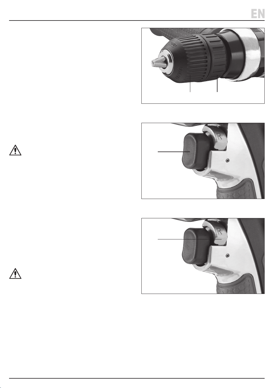
7.3 Directional control Switch (Fig.5)
• Slide the switch (3) to change the direction for either
(F) forward or (R ) for reverse.
• Use the trigger switch to adjust the speed setting most
suitable for the application. ONLY switch direction
when the chuck has stopped rotating
WARNING! Changing direction while the chuck
is rotating will damage the gearbox.
7. Operating Instructions
EN
Fig. 3
Fig. 4
Fig. 5
(1.2) (1.1)
(7)
(3)

– 10 –
7.4 Using the Drill
Dust and Swarf
• ALWAYS wear safety glasses and a correctly tted
dust when using the drill.
• A mask rated at least FFP2 should be used if the
application involves exposure to ne wood dust.
• Swarf produced by metal drilling is extremely sharp.
Take care when clearing metal swarf.
• The ‘burr’ left on the edge of the workpiece is also
sharp and should be removed with a suitable tool.
Drilling Wood and Plastic
• To prevent splitting around the drill holes on the
reverse side, place a piece of scrap timber under the
material to be drilled.
Drilling Metal
• The drill is suitable for use with metals such as sheet
steel, aluminium and brass.
• To help the drill bit to locate mark the point to be
drilled with a centre punch.
• Add a drop of oil on the cutting point to help aid
penetration and prolong the life of the drill bit.
Screwdriving
• To prevent slipping or damage to the screw head,
match the screwdriver bit to the screw head size.
7. Operating Instructions
EN
8. To Maintenance Storage and Disposal
EN
• Always unplug from the air supply and switch o
before carrying out any cleaning or maintenance.
• Regularly inspect and clean the drill to keep it in good
working condition.
• Wipe over with a damp cloth only. DO NOT use
solvents or abrasives to clean the product.
• When not in use store the product in a dry safe place
out of the reach of children.
At the end of its working life, dispose of the product
responsibly and in line with local regulations. Recycle
where possible.
• DO NOT dispose of this product with domestic waste;
most local authorities provide appropriate recycling
facilities.

9. Troubleshooting
EN
Problem Possible Cause Remedy
Tool will not operate. Air ows
slightly from exhaust. Spindle
turns freely.
Motor or throttle seized with dirt. • Check for dirt in air inlet.
• Pour air tool lubricating oil into
air inlet.
• Operate trigger in short bursts
• Disconnect air line supply, then
turn drill chuck by hand.
Reconnect air supply.
• If motor fails to turn contact the
Draper Tools product helpline for
advice.
Tool runs slowly. Air ows slightly
from exhaust.
Rotor vane seized. • Pour air tool lubricating oil into
air inlet.
• Operate trigger in short bursts.
• Disconnect air supply, rotate drill
by hand. Reconnect air supply.
• If still not functional. contact the
Draper Tools product helpline for
advice.
Spindle seized. Motor vane broken. Contact the Draper Tools product
helpline for advice.
Tool will not shut o. ‘O’ rings throttle valve dislodged
from seat inlet valve.
Replace ‘O’ ring or contact the
Draper Tools product helpline for
advice.
– 11 –

10. Warranty
Draper Tools products are carefully tested and inspected
before shipment and are guaranteed to be free from
defective materials and workmanship.
Should the tool develop a fault, return the complete tool
to your nearest distributor or contact Draper Tools
directly. Contact information can be found at the back of
this manual.
Proof of purchase must be provided.
If, upon inspection, it is found that the fault occurring is
due to defective materials or workmanship, repairs will be
carried out free of charge. This warranty period covers
parts and labour for 6 months from the date of purchase.
This warranty does not apply to any consumable parts,
batteries or normal wear and tear, nor does it cover any
damage caused by misuse, careless or unsafe handling,
alterations, accidents, or repairs attempted or made by
any personnel other than the authorised Draper Tools
repair agent.
In all cases, to make a claim for faulty workmanship or
materials within the standard warranty period, please
contact or return the product to the place of purchase.
Proof of purchase may be required.
If the place of purchase is no longer trading or if you
experience any diculties with your warranty, please
contact Customer Services with the product details and
your proof of purchase. Contact details can be found at
the back of this manual.
If the tool is not covered by the terms of this warranty,
repairs and carriage charges will be quoted and charged
accordingly.
This warranty supersedes any other guarantees
expressed or implied and variations of its terms are not
authorised.
Your Draper Tools guarantee is not eective until you can
produce, upon request, a dated receipt or invoice to
verify your purchase within the guarantee period.
Please note that this warranty is an additional benet
and does not aect your statutory rights.
Draper Tools Limited
EN
– 12 –
– 13 –
11. Explanation of Symbols
Read the instruction manual
Wear safety glasses
Wear ear defenders
Wear protective gloves
Warning!
Warning! Risk of crushing!
Direction of rotation
European conformity
UK Conformity Assessed
EN

Notes
EN
– 14 –

Notes
– 15 –

© Published by Draper Tools Limited© Published by Draper Tools Limited
Delta International
Delta International BV
Oude Graaf 8
6002 NL
Weert
Netherlands
Contact Details
Draper Tools
Draper Tools Limited
Hursley Road
Chandler’s Ford
Eastleigh
Hampshire
SO53 1YF
UK
Website: drapertools.com
Email: [email protected]
Product Helpline: +44 (0) 23 8049 4344
Telephone Sales Desk: +44 (0) 23 8049 4333
General Enquiries: +44 (0) 23 8026 6355
Please contact the Draper Tools Product Helpline for repair and servicing enquiries.