
Due to regular upgrades of systems and products, ZKTeco could not guarantee exact consistency
betweenthe actual product and the written information in this manual.
Installation Guide
Model: LH1000
Lock Body: American Standard Mortise with 5 Latches
Version: 1.0

Precautions
Installation is recommended to be performed by a professional to avoid any
additional service charges that may cause due to improper product installation.
Please read this Installation Guide carefully or contact the Customer Care for any
queries regarding installation.
A new lock is always in open mode until it is unlocked once by a RFID S50/S70 IC Card
(13.56Mhz).
Please swipe the authorized Access Card, Time Sync Card and Room Card at the initial
usage.
To power on the lock, four alkaline AA batteries (not included in package) are
required. Non-alkaline and rechargeable batteries ARE NOT RECOMMENDED.
Do not remove the batteries when the lock is in working state.
The lock is equipped with mechanical keys for manual unlocking. Remove the
mechanical keys from the package and keep them safely.
This type of lock is suitable for a door thickness of 35 mm to 54 mm. If your door
thickness is more than this range, please contact us for customization.
Avoid contact with corrosive substances, and do not hang any objects on the
handle.
When the battery power is low, the lock will beep to remind the user to replace the
batteries. Please do not reverse the positive and negative terminals while replacing
the batteries.
The software within the lock manages the working of RFID cards. For more details,
refer the Software User Manual.
1.
2.
3.
4.
5.
6.
7.
8.
9.
10.
11.
For further queries, please contact the seller.

Table of Contents
What's in the Box.............................................................................................................1
Installation Diagram.......................................................................................................2
3. Install the Mortise.....................................................................................................................................3
4. Install Outdoor Unit............................................................................................................................4
Installation Procedure....................................................................................................2
2. Drill Holes on the Door......................................................................................................................3
1. Door Opening Direction.....................................................................................................2
5. Install Strike Plate and Box...............................................................................................................6
6. Test the Lock by Mechanical Key...........................................................................................................6
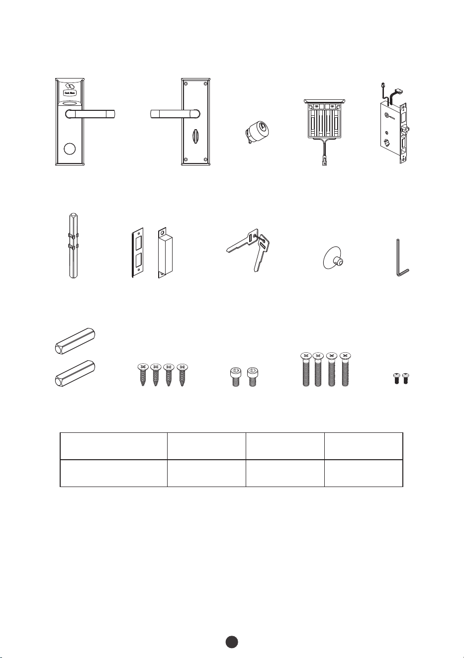
What's in the Box
Outdoor Unit Indoor Unit
Battery Box
Mortise
Spindle B
Spindle A
Strike Plate and Box
Keys
Vacuum Sucker
Hex Wrench
Screw A Screw B Screw C Screw D
1
Cylinder
Door Thickness
35 mm to 54 mm
Spindle A
40 mm
Screw C
55 mm
Spindle B
75 mm
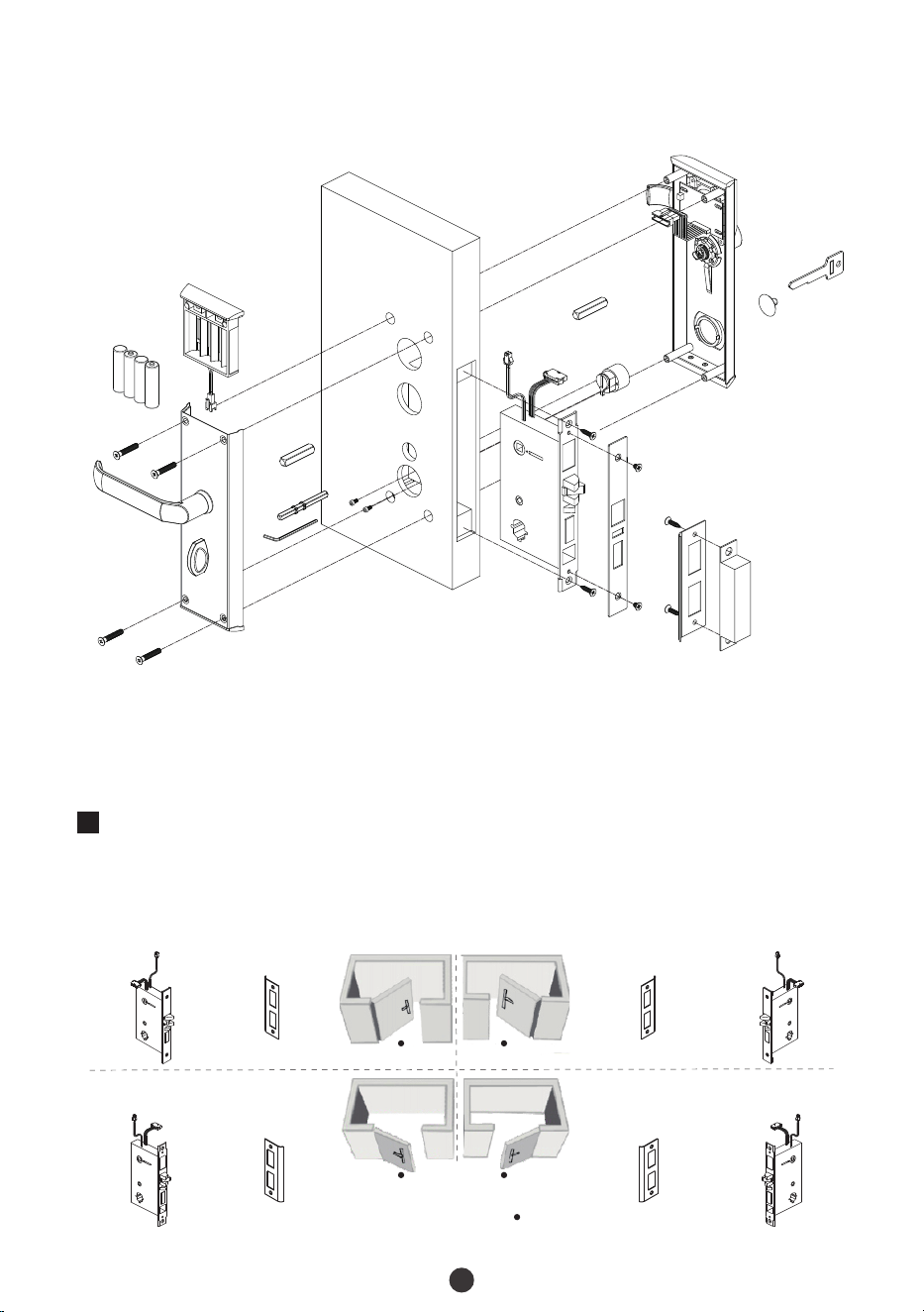
Installation Diagram
2
Installation Procedure
1
The handle position is determined by the swing (opening) direction of the door. Below is
the graphical representation of handle in reference to your location outside the room.
Battery Box
Battery
Screw C
Spindle A
Spindle B
H
e
x
W
r
e
nc
h
Indoor Unit
Scr
ew
B
Spindle A
Cylinder
Mortise
Screw A
Strike Plate and Box
Outdoor Unit
Cylinder
Cover
Key
Door
Door Opening Direction
Person Location
Left Inward
Right Inward
Left Outward
Right Outward
Mortise Strike Plate Strike Plate Mortise
Mortise Strike Plate Strike Plate Mortise
3
2
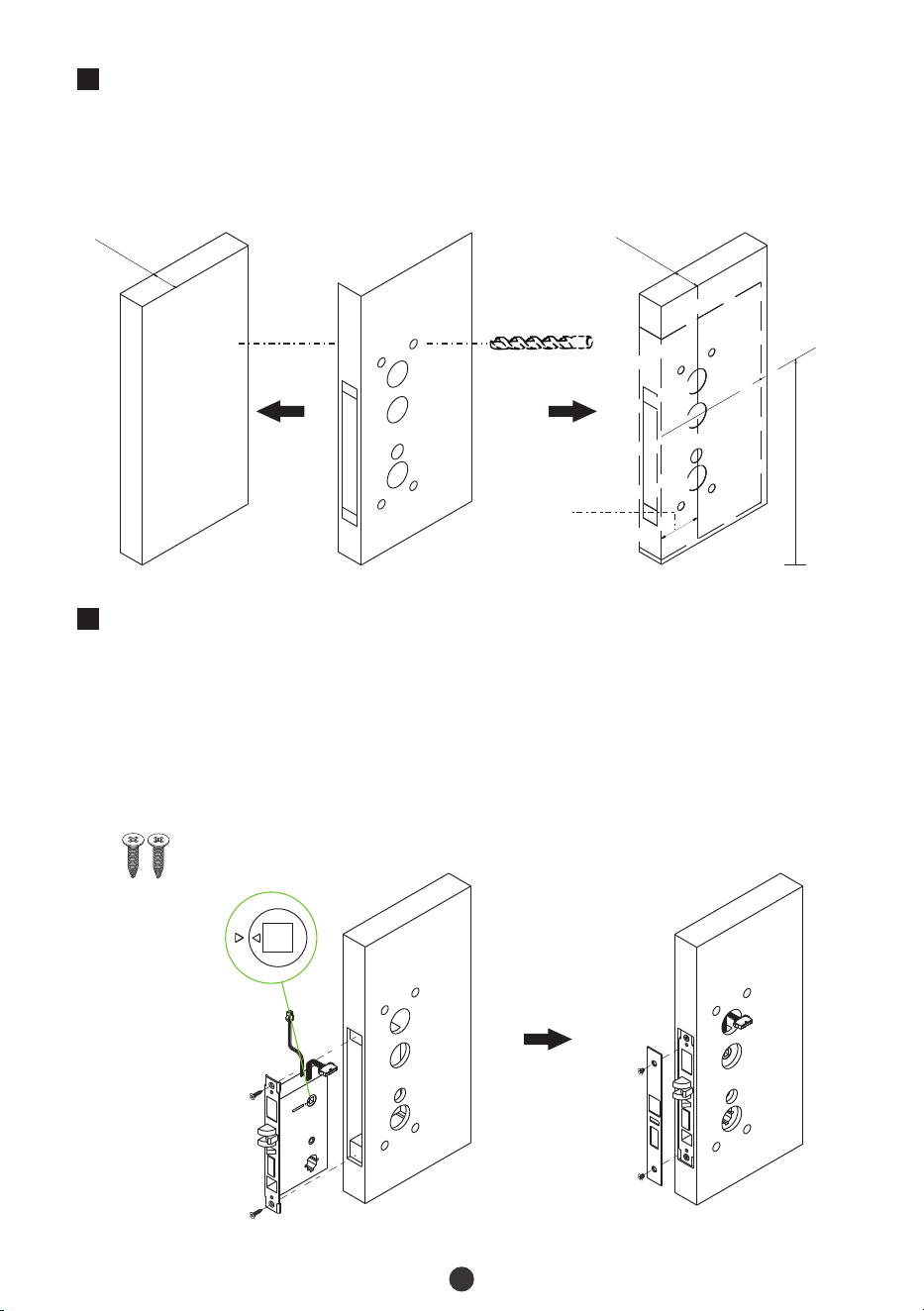
Drill Holes on the Door
Mark the holes to be drilled and drill the marked places.
Place the Installation template on the door at the desired handle height.
1)
2)
35 to 54 mm
Installation Template
De
s
ired han
dl
e h
e
i
g
h
t
Center line
of handle
Backset
62.5 mm
35 to 54 mm
3
Install the Mortise
Keep the two triangles on the clutch facing each other and then secure the mortise
with screw A.
1)
2)
Secure the lock plate with the screw. Make sure the Mainboard cable is towards
outdoor unit, and the power cable is towards indoor unit.
Screw A
F
4
4
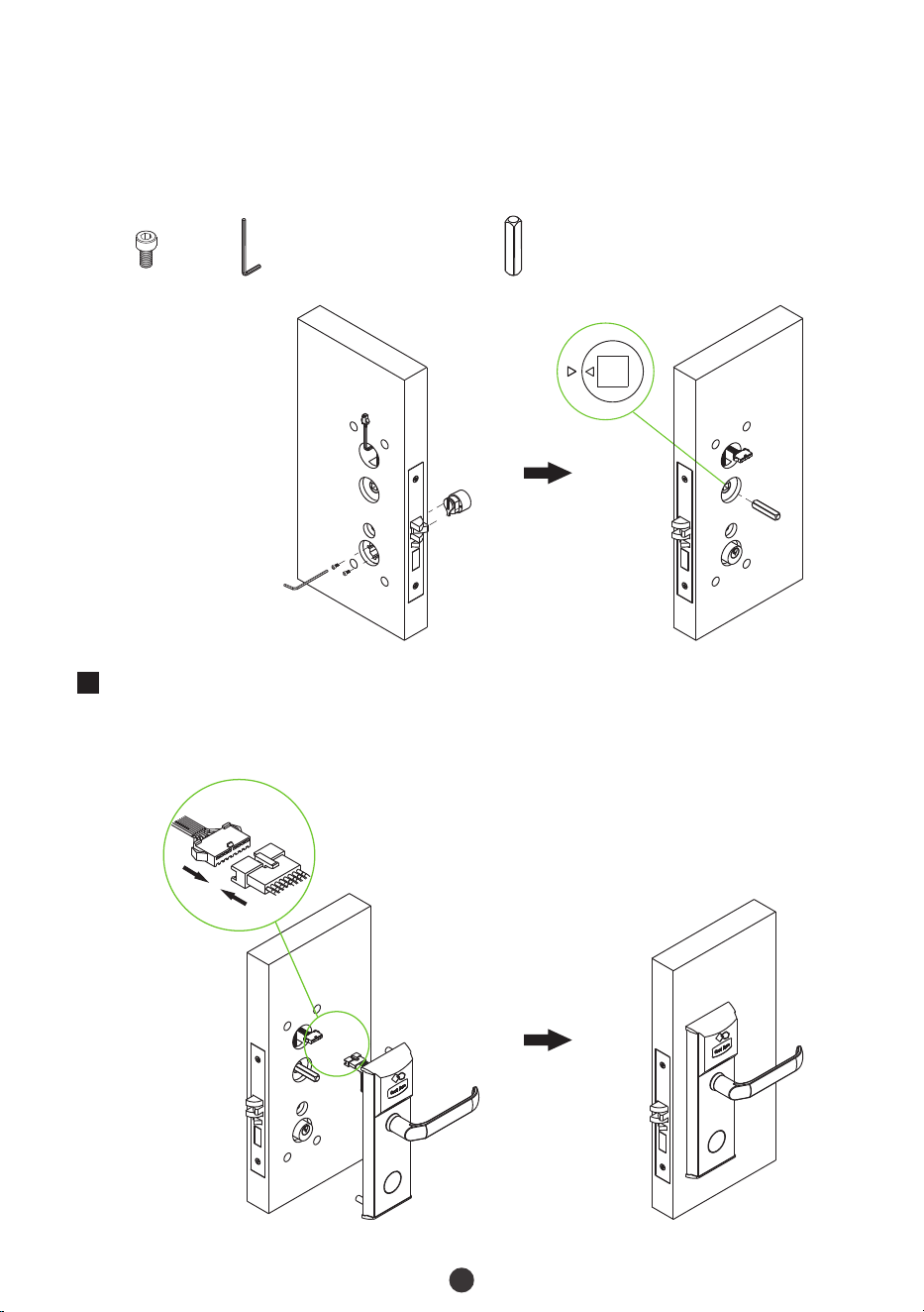
Install Outdoor Unit
Attach the outdoor unit to the door by inserting the cable through the drilled holes.
1)
Secure the cylinder with screw B by hex wrench. Make sure the cylinder is facing
towards the outdoor unit.
3)
4)
Insert the spindle A into the clutch facing towards outdoor unit and make sure the
two triangles are horizontal and facing each other.
Screw B
Hex Wrench Spindle A
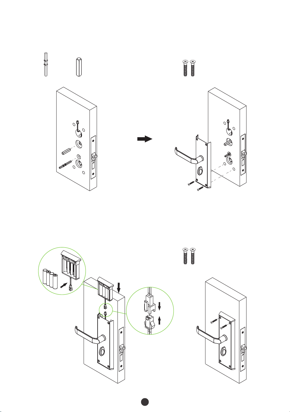
5
Insert the rest spindles into the mortise forward indoor unit.
2)
3)
Secure the lower section of the outdoor unit with screw C.
Spindle A
Spindle B
Screw C
4)
Connect the battery box cable and insert four Alkaline AA batteries. Then, insert the
battery box into the indoor unit.
5)
Secure the battery box and indoor unit with screw C.
Screw C
6
6
5
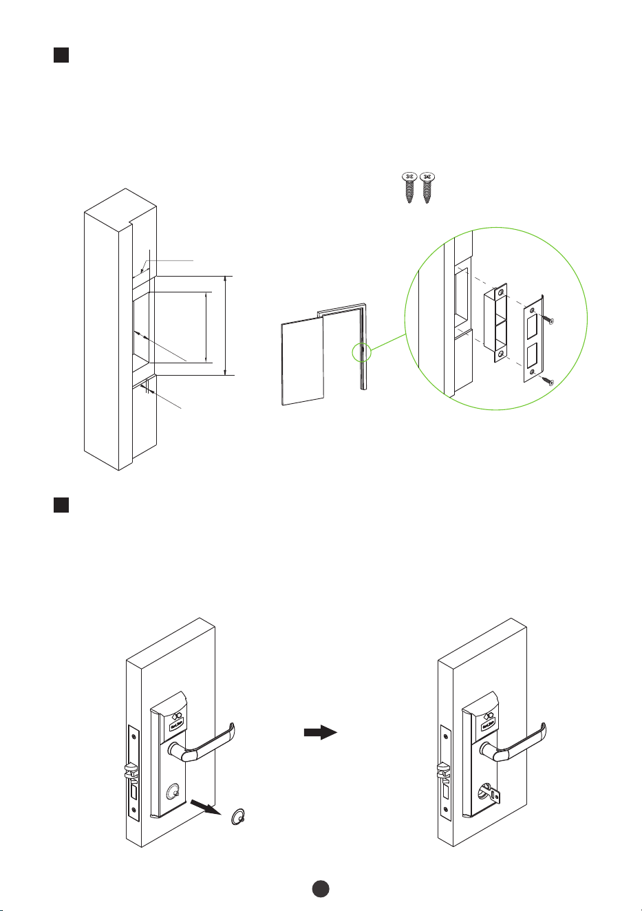
Install Strike Plate and Box
Make sure that the strike box is aligned with the latch bolt. Then, use the Installation
template to drill holes.
Align the strike plate and box with the drilled holes and secure them with screw A.
1)
2)
Screw A
3 mm
22 mm
125 mm
89 mm
25 mm
Test the Lock by Mechanical Key
Remove the cover on the key hole by the sucker provided.
Insert the key into the cylinder and rotate 90°. If the latch opens and beeps, it means
the lock is working normally.
1)
2)

This device complies with Part 15 of the FCC Rules. Operation is subject to the following
two conditions: (1) This device may not cause harmful interference, and (2) This device
must accept any interference received, including interference that may cause undesired
operation.
This equipment has been tested and found to comply with the limits for a Class B digital
device, pursuant to Part 15 of the FCC Rules. These limits are designed to provide
reasonable protection against harmful interference in a residential installation. This
equipment generates, uses, and can radiate radio frequency energy and, if not installed
and used in accordance with the instructions, may cause harmful interference to radio
communications. However, there is no guarantee that interference will not occur in a
particular installation. If this equipment does cause harmful interference to radio or
television reception, which can be determined by turning the equipment off and on, the
user is encouraged to try to correct the interference by one or more of the following
measures:
IMPORTANT! Any changes or modifications not expressly approved by the party
responsible for compliance could void the user's authority to operate the equipment.
Reorient or relocate the receiving antenna.
Increase the separation between the equipment and receiver.
Consult the dealer or an experienced radio/TV technician for help.
Warning:
FCC RF Radiation Exposure Statement:
This Transmitter must not be co-located or operating in conjunction with any other
antenna or transmitter.
This equipment complies with RF radiation exposure limits set forth for an
uncontrolled environment.
Connect the equipment into an outlet on a circuit different from that to which the
receiver is connected.

ZKTeco Industrial Park, No. 32, Industrial Road,
Tangxia Town, Dongguan, China.
Phone : +86 769 - 82109991
Fax : +86 755 - 89602394
www.zkteco.com
Copyright © 2024 ZKTECO CO., LTD. All Rights Reserved.