Warning notices: Before using this product, please read this manual carefully and keep it for future reference.
The design and specifications are subject to change without prior notice for product improvement.
Consult with the dealer or manufacturer for details.
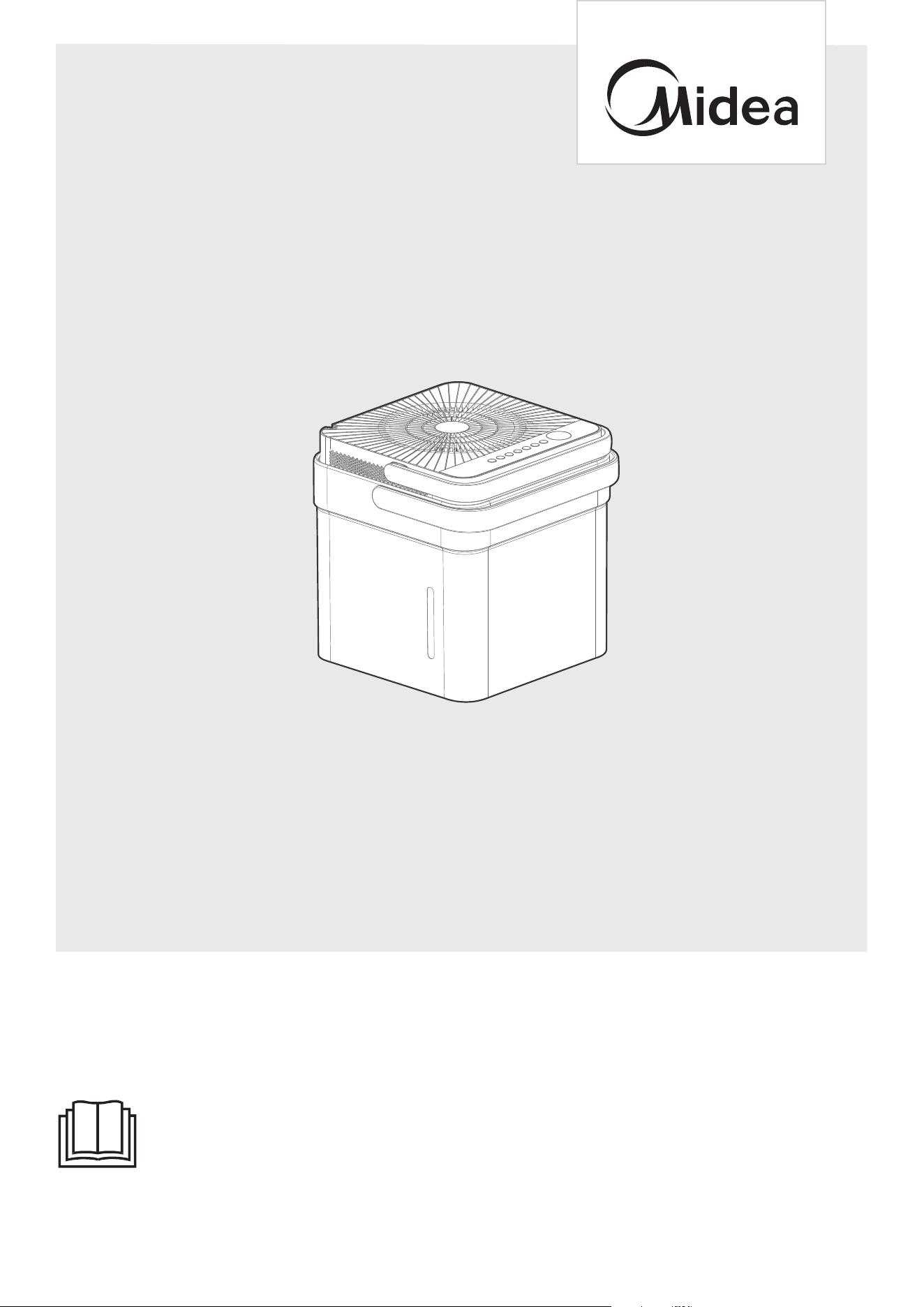
The diagram above is just for reference. Please take the appearance of the actual product as the standard.
MODEL NUMBER
USER MANUAL
DEHUMIDIFIER
MAD35S1QWT-A
MAD35S1QGR-A
MAD50S1QWT-A
MAD20S1QWT
MAD50PS1QWT-A
MAD50PS1QGR
MAD50PS1QWT-S
MAD50PS1QWT-B

THANK YOU FOR CHOOSING MIDEA!
Before using your new Midea product, please review this manual thoroughly to
ensure safe and effective operation of its features and functions.
01
CONTENTS
01
02
11
12
13
15
18
20
21
22
23
27
28
28
29
CONTENTS
SAFETY PRECAUTIONS
PRODUCT OVERVIEW
SET UP INSTRUCTIONS
INSTALLATION INSTRUCTIONS
OPERATION INSTRUCTIONS
REMOVING COLLECTED WATER
CLEANING AND MAINTENANCE
NESTING AND STORING INSTRUCTIONS
TROUBLESHOOTING TIPS
APP INSTRUCTIONS
WARRANTY
TRADEMARKS, COPYRIGHTS AND LEGAL STATEMENT
DISPOSAL AND RECYCLING
DATA PROTECTION NOTICE
This manual contains helpful tips for the proper use and maintenance of the
dehumidifier. Implementing preventive care can save significant time and money
throughout the unit's lifespan.
Read This Manual
SAFETY PRECAUTIONS
WARNING
This symbol indicates a hazardous situation which, if not avoided,
could result in death or serious injury.
CAUTION
This symbol indicates a hazardous situation which, if not avoided,
could result in minor or moderate injury.
Explanation of Symbols
02
WARNING
NOTICE
All the pictures in this manual are for illustrative purposes only. The actual shape
functions are similar.
To prevent injury to the user, or personal and property damage, these instructions
must be followed. Incorrect operation due to ignoring of instructions may cause
harm or damage. The level of risk is shown by the following indications.
Do not modify power cord length or share the outlet with other appliances.
It may cause electric shock or fire due to overheating.
Do not operate or stop the unit by inserting or pulling out the power plug.
It may cause electric shock.
Do not allow water to enter into electric parts. It may cause failure or electric shock.
Do not use the power outlet if it is loose or damaged.
It may cause fire and electric shock.
Do not use or keep the power cord close to heating appliances or heat sources
such as fireplaces. It may cause fire and electric shock.
Do not disassemble or modify unit. It may cause failure and electric shock.
Do not damage or use an unspecified power cord.
It may cause fire and electric shock.
Do not use the unit near flammable gas or combustibles, such as gasoline, benzene,
thinner, etc. It may cause fire.
Do not operate with wet hands. It may cause electric shock.
Do not open the unit during operation. It may cause electric shock.
Do not drink the water from the bucket.
CAUTION
For support, please call the Service Center at 1-866-646-4332.
This unit is not intended for use by people (including children) with reduced
physical, sensory, or mental capabilities or lack of experience and knowledge,
unless they have been given supervision or instruction concerning use of the
appliance by a person responsible for their safety.
Children should be supervised to ensure that they do not play with the unit.
The unit shall be installed in accordance with National wiring regulations and
local electrical codes.
purchased dehumidifier and
03
WARNING
Do not use the unit in small spaces or place in a sink or shower.
Lack of ventilation can cause overheating and fire.
Repairs to the unit should not be attempted independently.
Avoid fire hazard or electric shock.
Do not use an extension cord or an adaptor plug.
Do not remove any prongs from the power cord.
Plug in power plug properly.
Otherwise, it may cause electric shock or fire due to excess heat generation.
Unplug the unit if strange sounds, smells, or smoke are present.
A damaged product may cause fire and electric shock.
Ventilate room before operating the unit if there is a gas leak from other appliances.
If the power cord is damaged, it must be replaced by the manufacturer or an
authorized service center in order to avoid electrical risk.
Be sure the dehumidifier has been securely and correctly installed according to the
Before cleaning, turn off the power and unplug the unit.
installation instructions in this manual. Save this manual for possible future use in
removing or installing this unit.
Be sure the dehumidifier is properly grounded. To minimize shock and fire hazards,
proper grounding is important. The power cord is equipped with a three-prong
grounding plug for protection against shock hazards.
The dehumidifier must be used with a properly grounded wall receptacle. If the wall
receptacle is not adequately grounded or protected by a time delay fuse or circuit
breaker, have a qualified electrician install the proper receptacle.
Ensure the receptacle is accessible before the unit installation.
Ensure that the electrical service is adequate for the selected model.
This information can be found on the serial plate, which is located on the side of the
cabinet and behind the grille.
Make sure the bucket is empty of water before nesting unit.
If not, it could cause could cause electric shock and/or damage the unit.
Unplug the unit before nesting it in the bucket.
If not, it could cause could cause electric shock and/or damage the unit.
When unplugging the unit, be sure to grab the plug, not the cord.
CAUTION
Do not use in places where water may splash onto the unit. Water may enter the
unit and degrade the insulation. It may cause an electric shock or fire.
Place the unit on a level, sturdy section of the floor. If the unit falls over, it may
cause water to spill and damage belongings, or cause electrical shock or fire.
Never insert fingers or other foreign objects into grilles or openings. Take special
care to warn children of these dangers. It may cause failure or electric shock.
Do not climb up on or sit on the unit.
Injury may occur if there is a fall, whether from the user or the unit itself.
Always insert the filters securely, and take caution to avoid injuries to hand and
fingers. Clean filter once every two weeks.
Service Center at 1-866-646-4332.
04
CAUTION
power supply immediately. Visually inspect the unit to ensure there is no damage.
If damage has been suspected, contact customer service.
In a thunderstorm, the power should be disconnected to the unit due to lightning.
Do not run power cord under carpeting. Do not cover cord with throw rugs,
runners, or similar coverings. Do not route cord under furniture or appliances.
Do not place anything on top of the unit.
This would restrict airflow, possibly damage the unit and decrease performance.
Always lift unit with 2 hands using proper lifting technique.
Before turning the unit on, make sure it is seated correctly on the bucket.
Before lifting ensure the handle is properly attached.
Only use the bucket that came with the unit. Do not use any other bucket.
Clean the bucket regularly.
WARNING
CAUTION
CAUTION
CAUTION
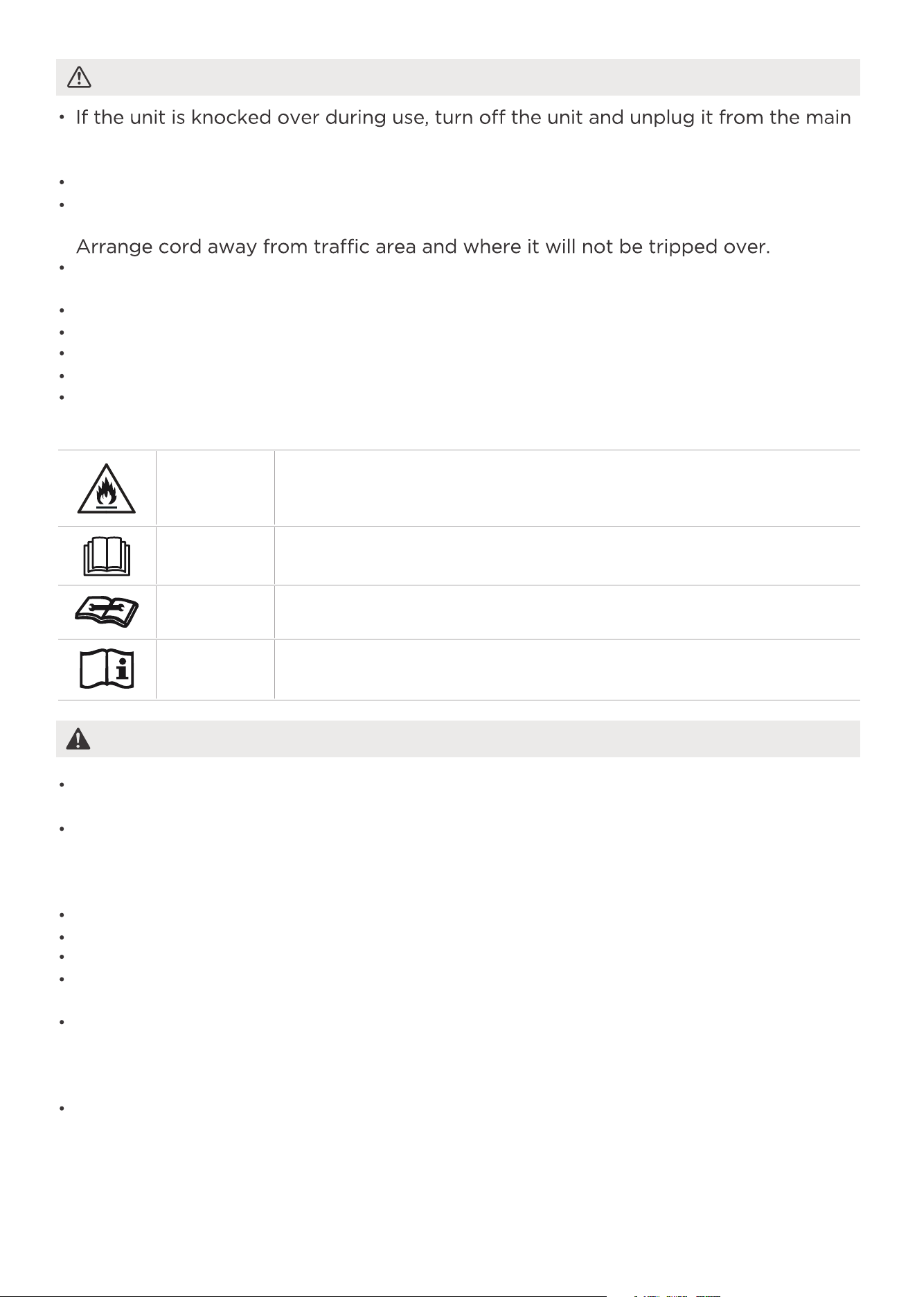
This symbol indicates that this appliance used a flammable
refrigerant. If the refrigerant is leaked and exposed to an
external ignition source, there is a risk of fire.
This symbol indicates that the operation manual should be
read carefully.
This symbol indicates that a service personnel should be handl-
ing this equipment with reference to the installation manual.
This symbol indicates that information is available such as the
operating manual or installation manual.
EXPLANATION OF SYMBOLS DISPLAYED ON THE UNIT
Do not try to accelerate the defrosting process or methods of cleaning that are not
recommended by the manufacturer.
The appliance shall be stored in a room without a continuously operating ignition
source (i.e. open flames or an operating gas appliance) or an ignition
source (i.e. an operating electric heater) close to the appliance. The
appliance shall also be stored in a room without ignition sources.
Do not pierce or burn.
Be aware that the refrigerants may not contain an odor.
Keep ventilation openings clear of obstruction.
Unit is only to be serviced by a Midea authorized servicer, please call Customer
Service at 1-866-646-4332 for support.
Flammable refrigerant R32 is used within air conditioner. Please follow the
instructions carefully to handle, install, clean, and service the air conditioner to
avoid damage or hazard. Do not dispose of air conditioner in regular trash. Contact
qualified agency for proper disposal.
No open fire or devices that generate spark/arcing shall be around the air
conditioner to avoid causing ignition of the flammable refrigerant used. Please
follow the instructions carefully to store or maintain the air conditioner to prevent
mechanical damage from occurring.
WARNING
05
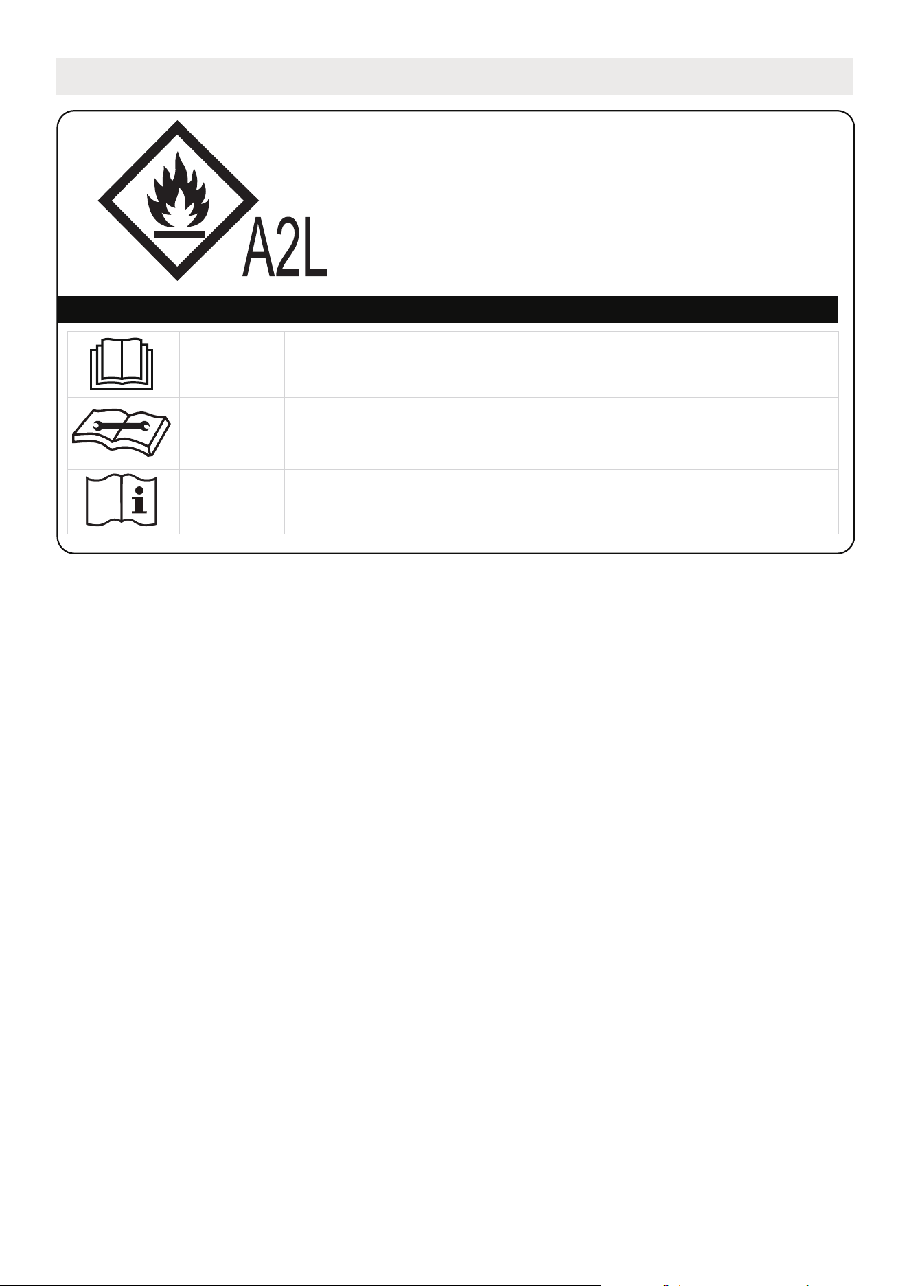
WARNING:
SAFETY PRECAUTIONS for R32 refrigerant model
CAUTION:
Risk of fire
flammable materials
Explanation of symbols displayed on the unit
CAUTION
This symbol indicates that the operation manual should
be read carefully.
CAUTION
This symbol indicates that a service personnel should be
handling this equipment with reference to the
installation manual.
CAUTION
This symbol indicates that information is available such
as the operating manual or installation manual.
- Servicing shall only be performed as recommended by the equipment manufacturer.
Maintenance and repair requiring the assistance of other skilled personnel shall be
carried out under the supervision of the person competent in the use of flammable
refrigerants.
- DO NOT modify the length of the power cord or use an extension cord to power
the unit.
- DO NOT share a single outlet with other electrical appliances. Improper power
supply can cause fire or electrical shock.
- Please follow the instruction carefully to handle, install, clear, service the appliance
to avoid any damage or hazard.
- When maintaining or disposing the appliance, the refrigerant shall b
e recovered
properly, shall not discharge to air directly.
- Compliance with national gas regulations shall be observed.
- Keep ventilation openings clear of obstruction.
- The appliance shall be stored so as to prevent mechanical damage from occurring.
- A warning that the appliance shall be stored in a well-ventilated area where the
room size corresponds to the room area as specified for operation.
- Any person who is involved with working on or breaking into a refrigerant circuit
should hold a current valid certificate from an industry-accredited assessment
authority, which authorises their competence to handle refrigerants safely in
accordance with an industry recognised assessment specification. All training shall
follow the ANNEX HH requirements of UL 60335-2-40 4th Edition.
Examples for such working procedures are:
• Breaking into the refrigerating circuit;
• Opening of sealed components;
• Opening of ventilated enclosures.

06
1) Checks to the area
Prior to beginning work on systems containing flammable refrigerants, safety checks
are necessary to ensure that the risk of ignition is minimized. For repair to the
refrigerating system, the following precautions shall be complied with prior to
conducting work on the system.
2) Work procedure
Work shall be undertaken under a controlled procedure so as to minimize the risk of
a flammable gas or vapor being present while the work is being performed.
3) General work area
All maintenance staff and others working in the local area shall be instructed on the
nature of work being carried out. Work in confined spaces shall be avoided.
The area around the workspace shall be sectioned off. Ensure that the conditions
within the area have been made safe by control of flammable material.
4) Checking for presence of refrigerant
The area shall be checked with an appropriate refrigerating detector prior to and
during work, to ensure the technician is aware of potentially flammable atmospheres.
Ensure that the leak detection equipment being used is suitable for use with
flammable refrigerants. (i.e. non-sparking, adequately sealed or intrinsically safe)
5) Presence of fire extinguisher
If any hot work is to be conducted on the refrigeration equipment or any associated
parts, appropriate fire extinguishing equipment shall be available to hand. Have a
dry powder or CO
2 fire extinguisher adjacent to the charging area.
6) No ignition sources
No person carrying out work in relation to a refrigerating system which involves
exposing any pipe work that contains or has contained flammable refrigerant shall
use any sources of ignition in such a manner that it may lead to the risk of fire or
explosion. All possible ignition sources, including smoking, should be kept sufficiently
far away from the site of installation, repairing, removing and disposal, during which
flammable refrigerant can possibly be released to the surrounding space. Prior to
work taking place, the area around the equipment is to be surveyed to make sure
that there are no flammable hazards or ignition risks. "No Smoking" signs shall be
displayed.
6. Information on servicing
See transport regulations.
1. Transport of equipment containing flammable refrigerants
See local regulations.
2. Marking of equipment using signs
See national regulations.
3. Disposal of equipment using flammable refrigerants
4. Storage of equipment
Storage package protection should be constructed such that mechanical
damage to the equipment inside the package will not cause a leak of the
refrigerant charge. The maximum number of pieces of equipment permitted to
be stored together will be determined by local regulations.
5. Storage of packed (unsold) equipment
The storage of the unit should be in accordance with the applicable regulations
or instructions, whichever is more stringent.

07
7) Ventilated area
Ensure that the area is in the open or that it is adequately ventilated before breaking
into the system or conducting any hot work. A degree of ventilation shall continue
during the period that the work is carried out. The ventilation should safely disperse
any released refrigerant and preferably expel it externally into the atmosphere.
8) Checks to the refrigerating equipment
Where electrical components are being changed, they shall be fit for the purpose
and to the correct specifications. At all times the manufacturer's maintenance and
service guidelines shall be followed. If in doubt consult the manufacturer's technical
department for assistance. The following checks shall be applied to installations
using flammable refrigerants: the actual refrigerant charge is in accordance with the
room size within which the refrigerant containing parts are installed; the ventilation
machinery and outlets are operating adequately and are not obstructed; if an
indirect refrigerating circuit is being used, the secondary circuit shall be checked for
the presence of refrigerant; marking to the equipment continues to be visible and
legible.
Markings and signs that are illegible shall be corrected; and refrigerating pipe or
components are installed in a position where they are unlikely to be exposed to
any substance which may corrode refrigerant containing components, unless the
components are constructed of materials which are inherently resistant to being
corroded or are suitably protected against being so corroded.
9) Checks to electrical devices
Repair and maintenance to electrical components shall include initial safety checks
and component inspection procedures. If a fault exists that could compromise safety,
then no electrical supply shall be connected to the circuit until it is satisfactorily dealt
with. If the fault cannot be corrected immediately but it is necessary to continue
operation, an adequate temporary solution shall be used.
This shall be reported to the owner of the equipment so all parties are advised.
Initial safety checks shall include: That capacitors are discharged: this shall be done
in a safe manner to avoid possibility of sparking; that there no live electrical
components and wiring are exposed while charging, recovering or purging the
system; that there is continuity of earth bonding.
7. Sealed electrical components shall be replaced.
8. Intrinsically safe components must be replaced.
Check that cabling will not be subject to wear, corrosion, excessive pressure,
vibration, sharp edges or any other adverse environmental effects. The check shall
also take into account the effects of aging or continual vibration from sources such
as compressors or fans.
9. Cabling

08
When breaking into the refrigerant circuit to make repairs—or for any other
purpose - conventional procedures shall be used. However, for flammable
refrigerants it is important that best practice be followed, since flammability is
a consideration. The following procedure shall be adhered to:
-Safely remove refrigerant following local and national regulations;
-Evacuate;
-Purge the circuit with inert gas (optional for A2L);
-Evacuate (optional for A2L);
-Continuously flush or purge with inert gas when using flame to open circuit; and
-Open the circuit.
The refrigerant charge shall be recovered into the correct recovery cylinders if
venting is not allowed by local and national codes. For units containing flammable
refrigerants, the system shall be purged with oxygen-free nitrogen to render the
appliance safe for flammable refrigerants. This process may need to be repeated
several times. Do not use compressed air or oxygen to purge refrigerant systems.
For units containing flammable refrigerants, refrigerants purging shall be
achieved by breaking the vacuum in the system with oxygen-free nitrogen and
continuing to fill until the working pressure is achieved, then venting to
atmosphere, and finally pulling down to a vacuum (optional for A2L).
This process shall be repeated until no refrigerant is within the system (optional
for A2L). When the final oxygen-free nitrogen charge is used. the system shall be
vented down to atmospheric pressure to enable work to take place. The outlet
for the vacuum pump shall not be close to any potential ignition sources, and
ventilation shall be available.
11. Removal and evacuation
Under no circumstances shall potential sources of ignition be used in the searching
for or detection of refrigerant leaks. A halide torch (or any other detector using a
naked flame) shall not be used.
The following leak detection methods are deemed acceptable for systems
containing flammable refrigerants. Electronic leak detectors shall be used to detect
flammable refrigerants, but the sensitivity may not be adequate, or may need
re-calibration. (Detection equipment shall be calibrated in a refrigerant-free area.)
Ensure that the detector is not a potential source of ignition and is suitable for the
refrigerant used. Leak detection equipment shall be set at a percentage of the LFL
of the refrigerant and shall be calibrated to the refrigerant employed and the
appropriate percentage of gas (25 % maximum) is confirmed. Leak detection fluids
are suitable for use with most refrigerants but the use of detergents containing
chlorine shall be avoided as the chlorine may react with the refrigerant and corrode
the copper pipe-work. If a leak is suspected, all naked flames shall be removed/
extinguished. If a leakage of refrigerant is found which requires brazing, all of the
refrigerant shall be recovered from the system, or isolated (by means of shut off
valves) in a part of the system remote from the leak. Removal of refrigerant shall
be according to Removal and evacuation.
10. Detection of flammable refrigerants

09
Before carrying out this procedure, it is essential that the technician is completely
familiar with the equipment and all its detail. It is recommended good practice
that all refrigerants are recovered safely.
Prior to the task being carried out, an oil and refrigerant sample shall be taken in
case analysis is required prior to re-use of reclaimed refrigerant. It is essential
that electrical power is available before the task is commenced.
a) Become familiar with the equipment and its operation.
b) Isolate system electrically.
c) Before attempting the procedure ensure that: Mechanical handling equipment
is available, if required, for handling refrigerant cylinders; all personal protective
equipment is available and being used correctly; the recovery process is
supervised at all times by a competent person; recovery equipment and
cylinders conform to the appropriate standards.
d) Pump down refrigerant system, if possible.
e) If a vacuum is not possible, make a manifold so that refrigerant can be
removed from various parts of the system.
f) Make sure that cylinder is situated on the scales before recovery takes place.
g) Start the recovery machine and operate in accordance with manufacturer's
instructions.
h) Do not overfill cylinders. (No more than 80 % volume liquid charge).
i) Do not exceed the maximum working pressure of the cylinder, even temporarily.
j) When the cylinders have been filled correctly and the process completed, make
sure that the cylinders and the equipment are removed from site promptly and
all isolation valves on the equipment are closed off.
k) Recovered refrigerant shall not be charged into another refrigeration system
unless it has been cleaned and checked.
In addition to conventional charging procedures, the following requirements shall
be followed.
Ensure that contamination of different refrigerants does not occur when using
charging equipment.
Hoses or lines shall be as short as possible to minimize the amount of refrigerant
contained in them.
Cylinders shall be kept in an appropriate position according to the instructions.
Ensure that the refrigeration system is earthed prior to charging the system with
refrigerant. Label the system when charging is complete (if not already). Extreme
care shall be taken not to overfill the refrigeration system. Prior to recharging the
system it shall be pressure tested with OFN. The system shall be leak tested on
completion of charging but prior to commissioning. A follow up leak test shall be
carried out prior to leaving the site.
12. Charging procedures
13. Decommissioning
Equipment shall be labeled stating that it has been de-commissioned and
emptied of refrigerant. The label shall be dated and signed. Ensure that there are
labels on the equipment stating the equipment contains flammable refrigerant.
14. Labeling
10
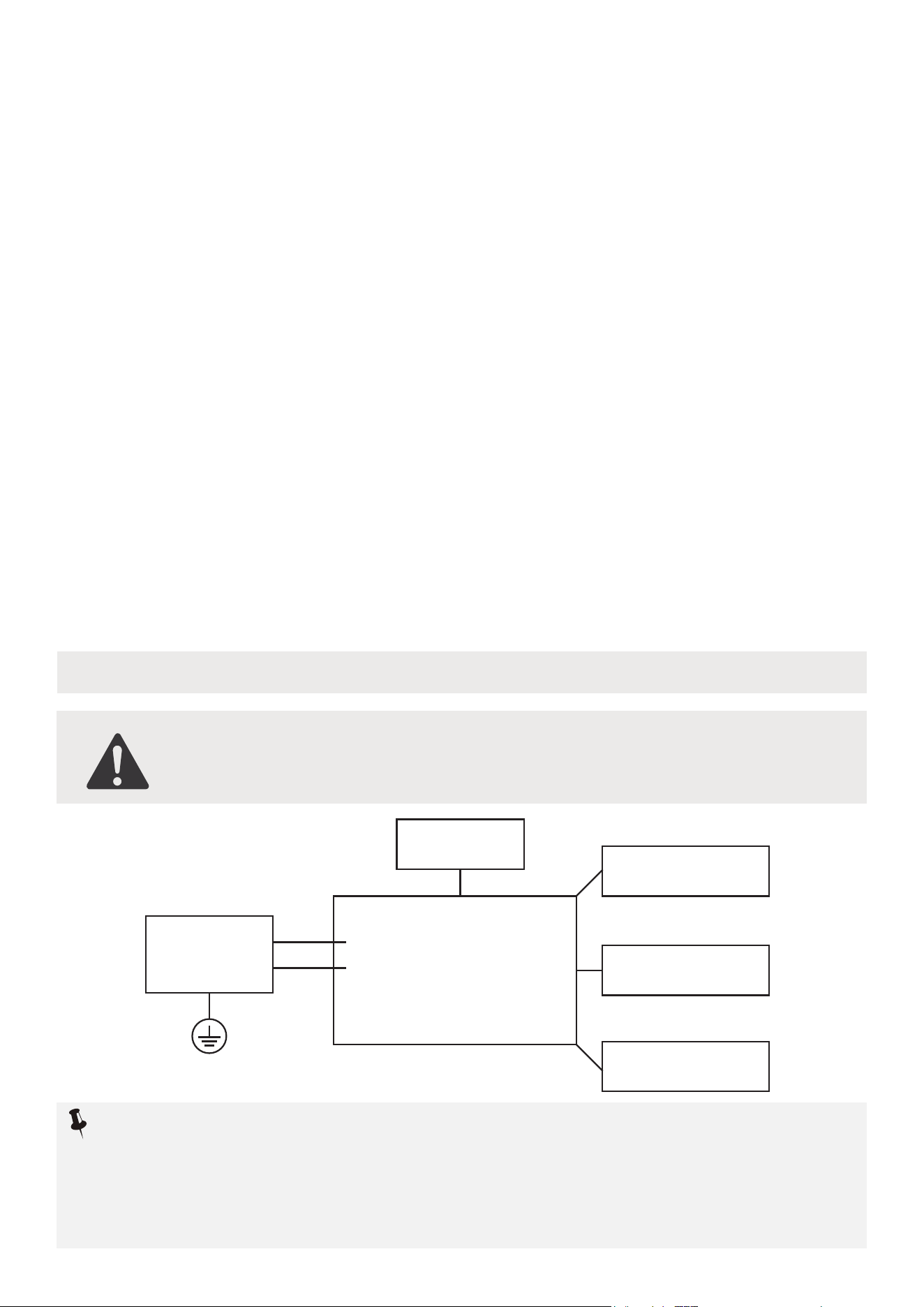
Electronic Work
WARNING:
BEFORE PERFORMING ANY ELECTRICAL OR WIRING WORK, TURN
OFF THE MAIN POWER TO THE SYSTEM.
Main Control
Compressor
Fan Motor
Display
Power
Supply
L/AC L/L1/L-IN
N/AC N/L2/N-IN
Other
Electronic Type
When removing refrigerant from a system, either for servicing or decommissioning,
it is recommended good practice that all refrigerants are removed safely. When
transferring refrigerant into cylinders, ensure that only appropriate refrigerant
recovery cylinders are employed. Ensure that the correct number of cylinders for
holding the total system charge is available. All cylinders to be used are designated
for the recovered refrigerant and labelled for that refrigerant (i.e. special cylinders
for the recovery of refrigerant). Cylinders shall be complete with pressure relief
valve and associated shut-off valves in good working order. Empty recovery
cylinders are evacuated and, if possible, cooled before recovery occurs. The
recovery equipment shall be in good working order with a set of instructions
concerning the equipment that is at hand and shall be suitable for the recovery of
the flammable refrigerant. If in doubt, the manufacturer should be consulted. In
addition, a set of calibrated weighing scales shall be available and in good working
order. Hoses shall be complete with leak-free disconnect couplings and in good
condition.
The recovered refrigerant shall be processed according to local legislation in the
correct recovery cylinder, and the relevant waste transfer note arranged. Do not
mix refrigerants in recovery units and especially not in cylinders. If compressors or
compressor oils are to be removed, ensure that they have been evacuated to an
acceptable level to make certain that flammable refrigerant does not remain within
the lubricant. The compressor body shall not be heated by an open flame or other
ignition sources to accelerate this process. When oil is drained from a system, it
shall be carried out safely.
15. Recovery
NOTICE:
Please strictly follow the wiring label attached to the machine for all wiring connections.
The wiring diagram may vary for different unit. Please refer to the wiring diagram on
the unit. The above wiring diagram is a simplified version for preliminary illustration
purposes only.
11
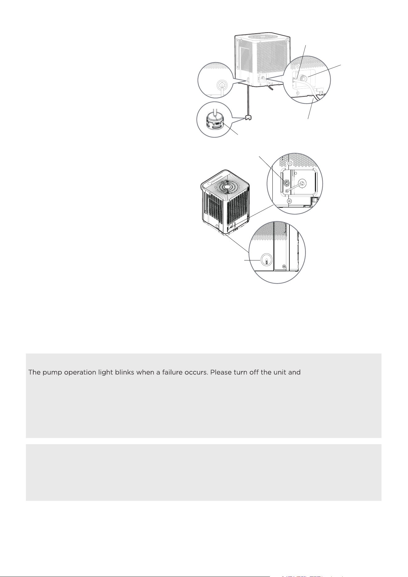
Pump drain hose
(only for units with the
drain pump feature)
Pump inlet hose (only
for units with the drain
pump feature)
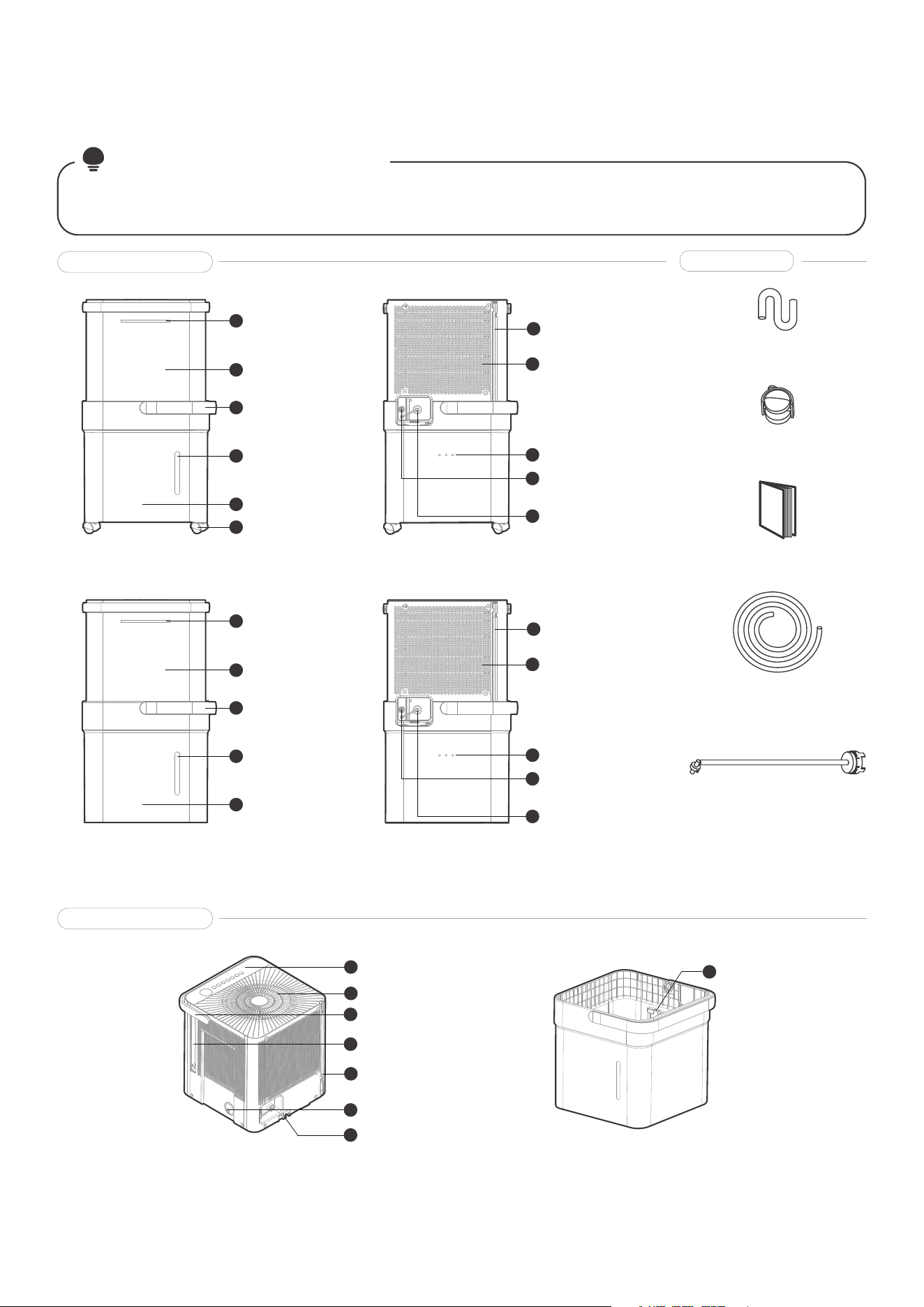
NOTE ON ILLUSTRATIONS:
PRODUCT OVERVIEW
All the illustrations in the manual are for explanation purpose only. The unit may be slightly different.
The actual shape shall prevail. The unit can be controlled by the unit control panel alone.
Model A-Back View
BucketDehumidifier
Pump hose
outlet(Optional)
Garden
hose outlet
Pump hose
outlet(Optional)
Garden
hose outlet
Power cord
storage
channel
Power cord
storage
channel
Relief Holes
Air intake
8
10
11
7
9
Model A-Front View
Front panel
Bucket handle
Bucket water
level window
Bucket
Quick glance
light (Optional)
Caster
(Optional)
1
2
3
4
5
6
Air outlet
Air filter handle
(Both Sides)
Bucket sensor
Power cord
Pump inlet hose
connection(Optional)
Control panel
and Display
Unit handle
12
14
13
16
18
15
17
Lock tabs
19
Product overview
Parts overview
Accessories
Model B-Back View
Relief Holes
Air intake
8
10
11
7
9
Model B-Front View
Front panel
Bucket handle
Bucket water
level window
Bucket
Quick glance
light (Optional)
1
2
3
4
5
Normal
drain hose
Owner’s
manual
Casters
(Optional)
Manual
12
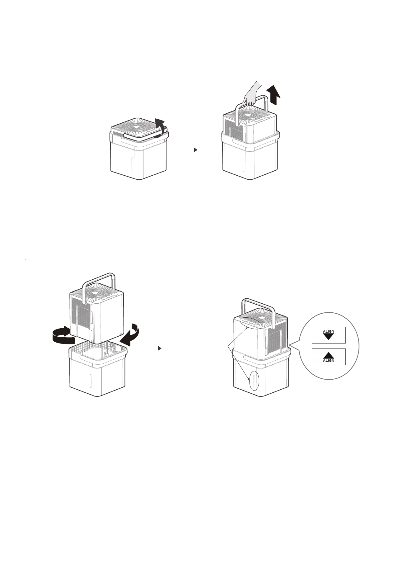
SET UP INSTRUCTIONS
Step 1:
Separate dehumidifier & bucket from the nested shipping/storage position. Remove all packaging materials
from the unit.
Step 2:
Rotate dehumidifier 90° and align the arrows on the two labels (one on the bucket and one on the
dehumidifier) and carefully sit the dehumidifier down onto the bucket. The water level window in the bucket
and the user interface buttons on the dehumidifier should be on the same side when properly stacked.
Check to ensure the arrows on the unit and bucket are aligned as in Fig. 4c for proper operation.
Step 3:
Plug the unit in and press the power button and the unit is ready to run in normal (bucket) mode.
Fig. 3a Fig. 3b
Nested Shipping & Storage Position
Rotate dehumidifier 90°
User Interface
Buttons and
Water Level
Window Aligned
on the same side
13
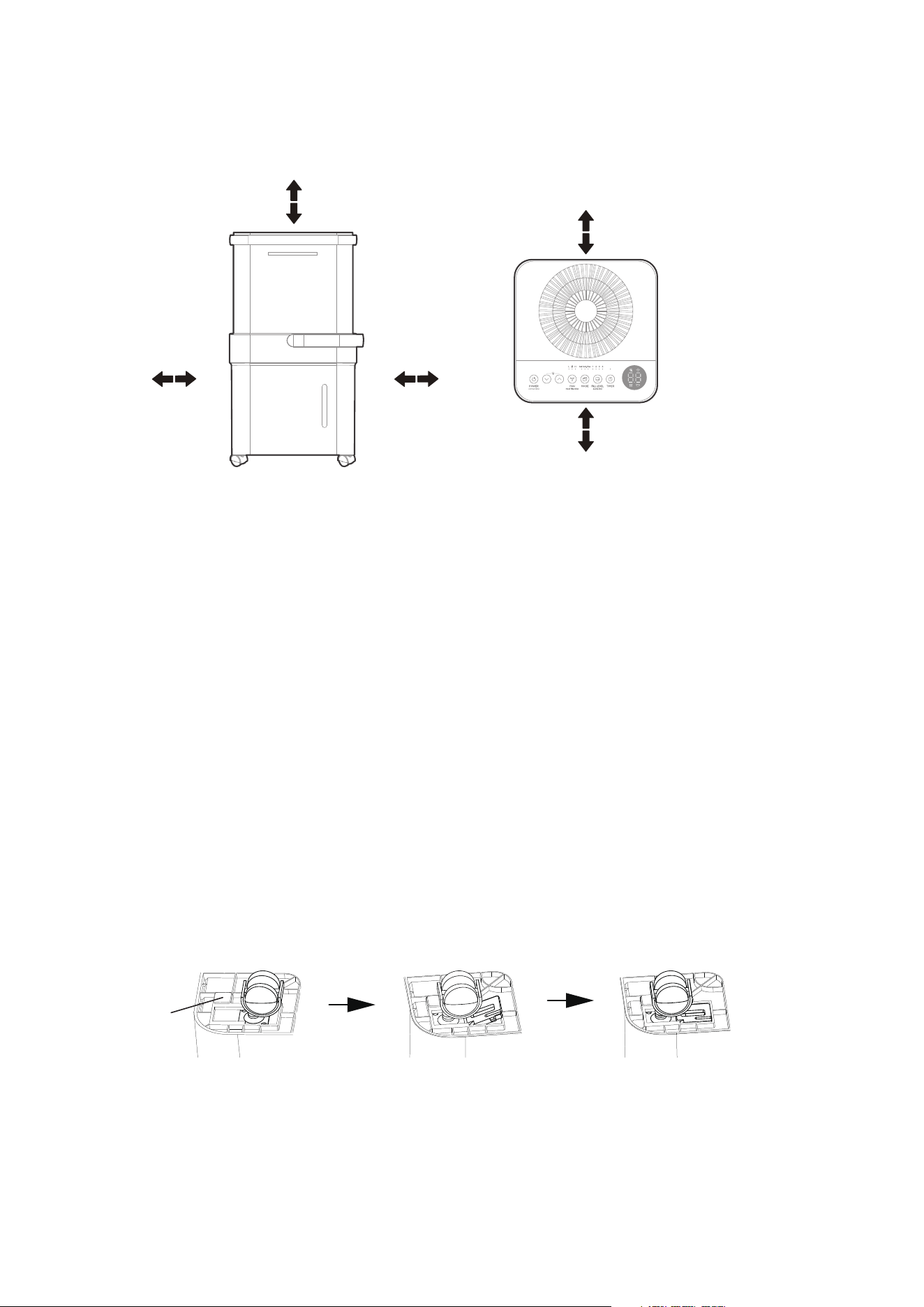
Positioning the Unit
The dehumidifier should be placed in the area where dehumidification is desired most. Adjacent rooms in
which dehumidification is also desired should allow adequate airflow in and out of the space containing the
dehumidifier.
• Do not use outdoors.
• This dehumidifer is intended for indoor residential
applications only. This dehumidifier should not be
used for commercial or industrial applications.
• Place the dehumidifier on a smooth, level floor
strong enough to support the unit with a full
bucket of water.
• Allow at least 8” of air space on all sides of the
unit for air circulation (at least 16” for air outlet).
• Place the unit in an area where the temperature
will not fall below 41°F (5°C). The coils can
become covered with frost at lower temperatures,
which may reduce performance.
• Place the unit away from any clothes dryer, heater
or radiator.
• Close all doors, windows, and other openings to
the outdoors in the room.
Fig. 5
INSTALLATION INSTRUCTIONS
More than
40cm(16”)
More than
40cm(16”)
More than
20cm(8”)
More than
20cm(8”)
More than
20cm(8”)
Front View Top View
Fig. 6
Optional Caster Installation
To install the casters:
1. Remove the Dehumidifier from the bucket.
2. Slide each caster into the slot on the bucket’s bottom corner as shown below.
3. Place the retaining block into the slot to hold the caster in place.
4. Repeat this for each corner of the bucket until all 4 casters are installed.
blockcaster
bottom
of unit
14
ADDITIONAL SETUP AND USAGE INFORMATION
Scan this QR code with a mobile device to see a playlist of helpful videos about
the new Cube Dehumidifier.
Fig. 7
To remove the casters:
1. Use a flathead screwdriver to actuate the tab on the retaining block.
2. Remove the retaining block and slide the casters out of the slot on the bucket.
Optional Caster Installation
NOTICE
With the casters attached, do not move the unit and bucket assembly while there
is water in the bucket. Before rolling the bucket, remove the unit.
15
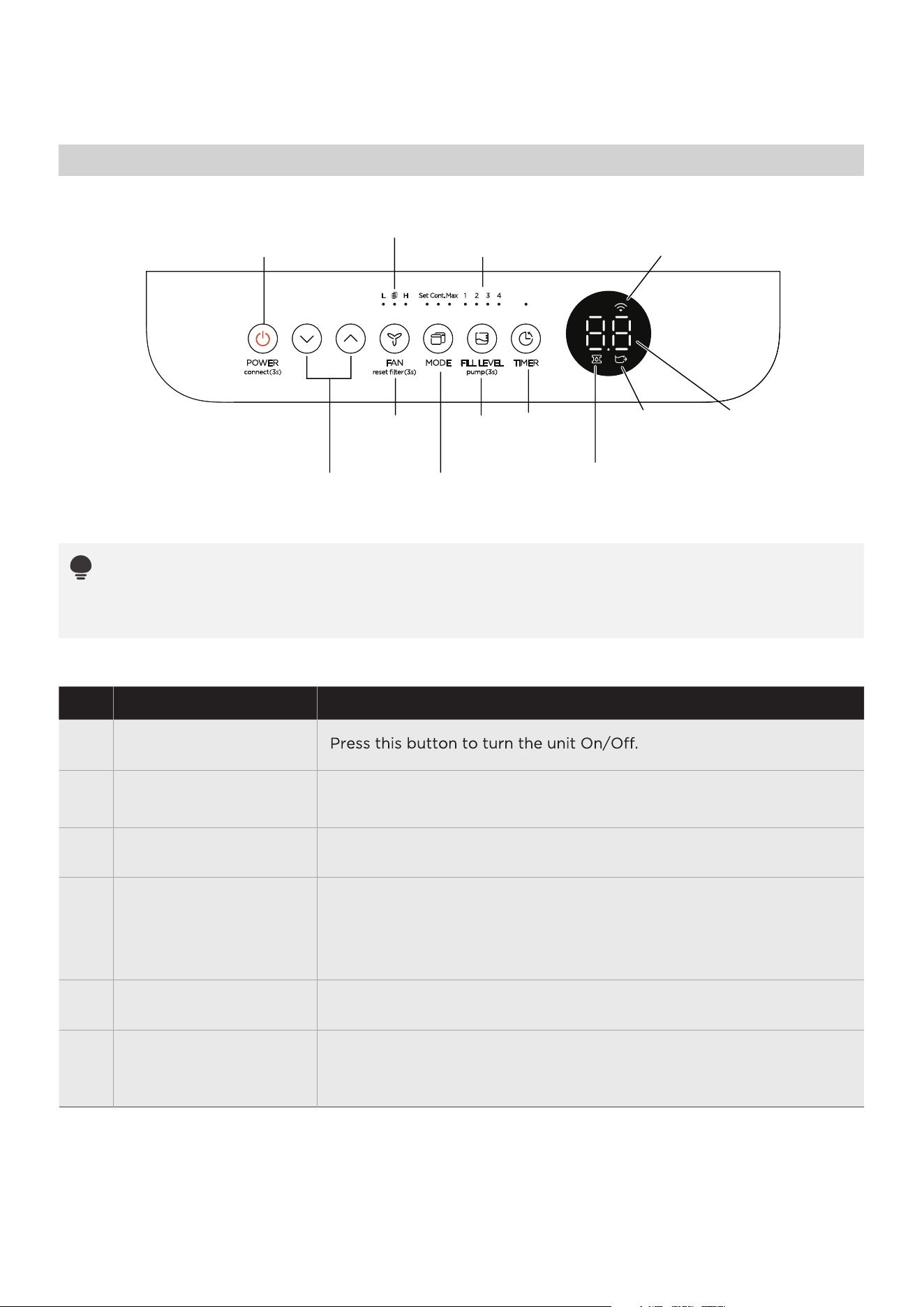
Control Panel
OPERATION INSTRUCTIONS
Fan Button
and Indicators
(reset filter)
Mode Button
and Indicators
Timer
Button and
Indicator
Fill Level
Button and
Indicators
Pump
Indicator
(some models)
Power Button
(connect)
Up/Down
Pump
(some
models)
Buttons
Connection
Indicator
LED DisplayBucketless
Indicator
Filter Indicator
NOTICE:
The appearance of the control panel on the unit may vary slightly. Functions will be similar.
When a button is pushed, the unit will make a beep sound to indicate that it is changing modes.
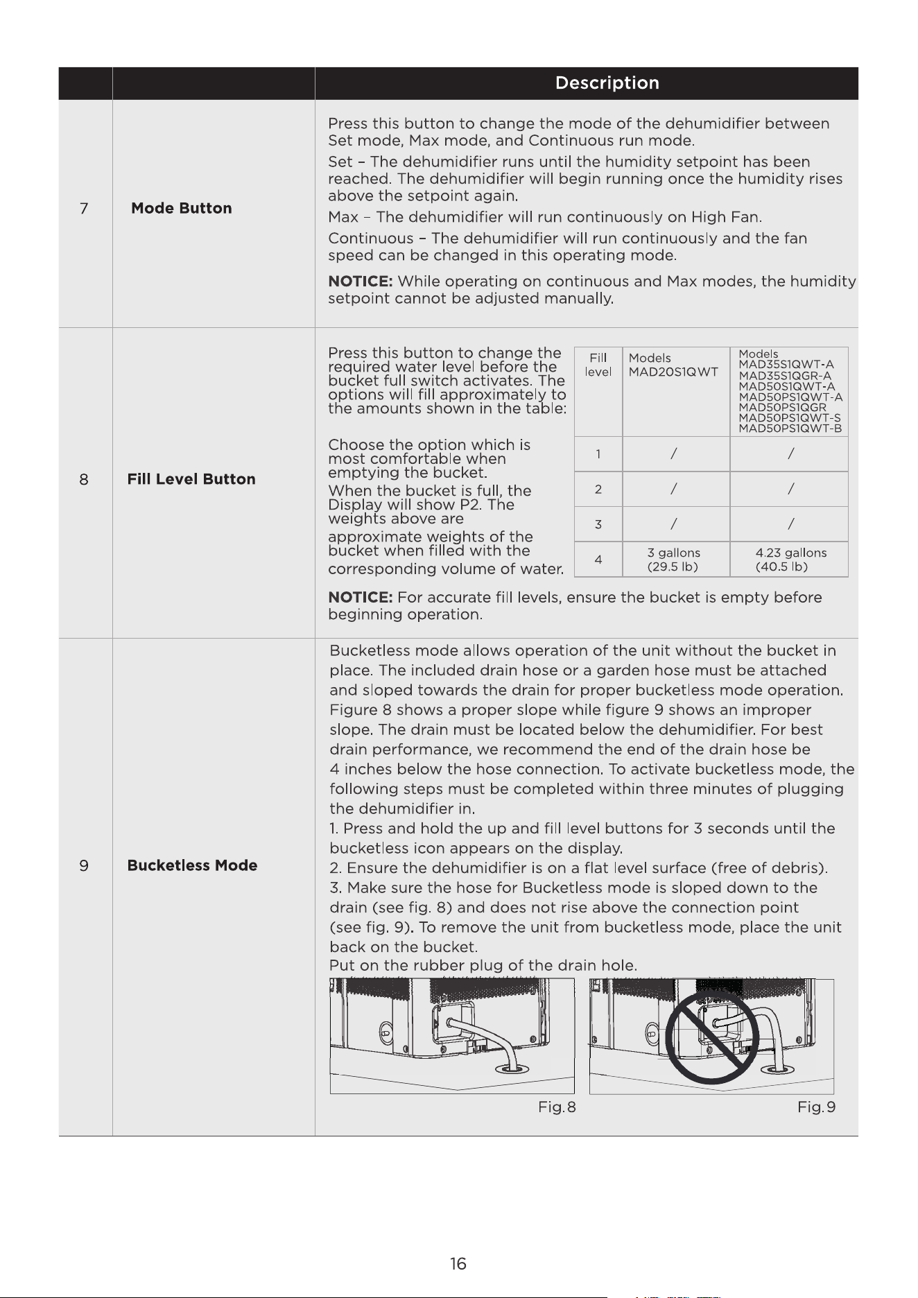
Description
Connect
1
3
4
5
2
Power Button
Holding the power button for 3 seconds will place the unit in network
connection mode to setup wireless control.
Up/Down Buttons
Press these buttons to adjust the setpoint or to set the time feature.
Press and hold on the Fill level pump 3 seconds to initiate PUMP
feature. Press and hold on the Fill level pump 3 seconds again to stop
PUMP feature. Turn on the PUMP feature, the bucket capacity cannot
be selected and the bucket capacity is at 4 step.
Pump
(On some models)
Fan Button
Press this button to change the fan speed between High and Low.
6
Filter Reset
To reset the change filter indicator, hold the fan button for 3 seconds.
NOTE: It will enter the filter cleaning reminder when the unit runs for
250 hours.
17
Other Features
NOTICE:
• When first using the dehumidifier, operate the unit
continuously 24 hours. Make sure the plastic cover
on the continuous drain hose outlet is installed
properly so there are no leaks.
• This unit is designed to operate in a working
environment between 5°C/41°F and 35°C/95°F.
• Make sure the water bucket is positioned correctly
so that the unit can operate properly. When the
water in the bucket reaches a certain level, please be
careful while moving the unit to avoid spilling.
Description
11
10
TIMER Button
Press this button to activate the Timer function. The Timer LED will
illuminate indicating timer mode is being set. 0.0 will also appear on
the display indicating the number of hours from now until the timer
function will initiate.
When the timer function initiates, the unit will change its power
state. For more information see Timer function under other features
on the next page.
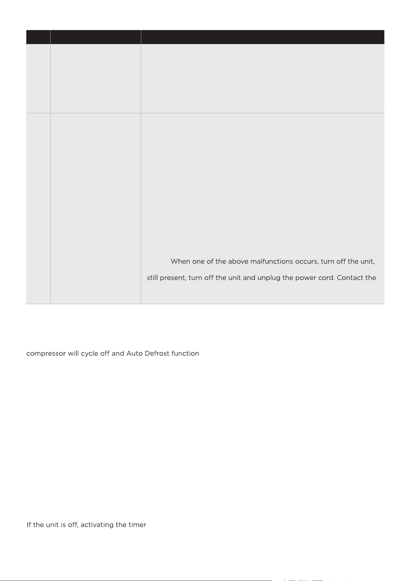
When frost builds up on the evaporator coils, the
will run automatically.
EH60
Room temperature sensor error
--Unplug the unit and plug it back in. If error repeats, call for service;
EH61
Tube Temperature sensor of the evaporator error
--Unplug the unit and plug it back in. If error repeats, call for service;
EH0b
Display board and master control board communication error.
--Unplug the unit and plug it back in. If error repeats, call for service;
Protection Code:
P2
Bucket is full
--Empty the bucket and replace it in the right position.
Eb
Bucket malfunction
--Replace the bucket in the right position, the malfunction clear.
NOTE:
and check for any obstructions. Restart the unit, if the malfunction is
manufacturer or its service agents or a similar qualified person for
service.
ERROR Codes
Auto Defrost
After the unit has stopped, it can not be restarted
in the first 3 minutes to protect compressor
operation. The unit will restart automatically after
3 minutes.
3 minutes compressor operation delay protection
If the unit stops unexpectedly due to power being
cut, it will restart with the previous function setting
(except bucketless mode) automatically when the
power resumes.
Auto-Restart
Timer Function
• Activating the Timer function sets the duration
until the unit changes its power state. This means,
if the unit is on, activating the timer function will
set the time until the unit will turn off.
set the time until the unit will turn on.
function will
• The time can be set after pressing the timer
button then using the up or down buttons. These
buttons will change the time in 0.5 hour increments
up to 10 hours. After 10 hours, the time will change
in 1 hour increments up to 24.
• If an error code appears during this time, the
timer function will be cancelled.
18
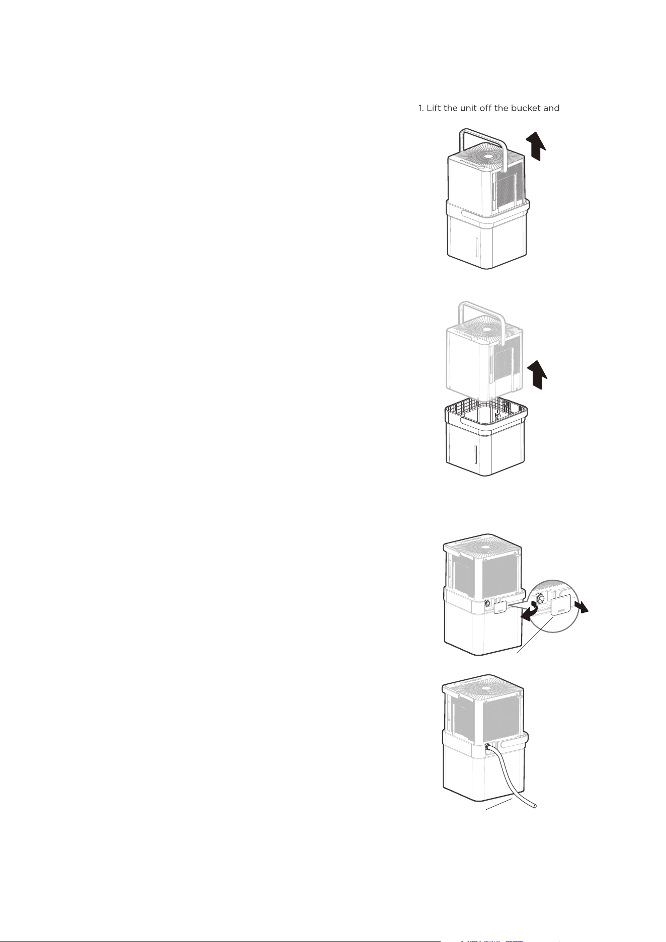
REMOVING COLLECTED WATER
There are three ways to remove collected water:
1. Emptying the bucket
• When the bucket reaches the set Fill Level, the unit’s
display will show P2 regardless of power status.
• Using proper lifting techniques, remove the unit from
the bucket. Be aware, some residual water may spill
from the bottom of the unit while not on the bucket.
• Using two hands, grab the bucket handle and carry
it to the desired drainage point. Pouring from a front
corner of the bucket (the bucket window is on the
front side), empty the bucket. If pouring from the
back of the bucket, some water may spill from the
relief holes.
• Return the bucket to the desired operating location
and place the unit back on the bucket. Be sure the
unit is aligned properly.
Fig. 10
Fig. 11
Fig. 12
Fig. 13
NOTICE:
NOTICE:
• When the unit is removed from the bucket, do not
set the unit on any electrical components as the
bottom may be wet.
• Do not set the unit on an uneven surface after
removing it from the bucket.
• Ensure the unit is seated properly after returning it
to the bucket.
• If the unit is removed from the bucket during
operation, the display will show the error code Eb
and cease operation until returned to the bucket
or changed to bucketless mode.
2. Continuous draining
• Water can be automatically emptied from the unit
into a sink, or other type of drain using the included
hose.
• To install the hose, remove the drain cap from the
rear of the unit and set aside. Insert the included drain
hose, or attach a garden hose to the drain outlet.
Place the other end of the hose on or near the drain
so that water will drain properly.
place it on a level surface.
2. Lift the bucket using 2 hands
and carry to drainage point.
3. Pour out all of the water.
Remove the cover.
Drain hose
Remove the plastic
cover rotating
counter-clockwise.
When using the continuous draining feature,
ensure the unit is placed above the sink or drain
being used. This will ensure proper draining.
• When removing the drain hose, some water
may remain in the hose or the drain outlet.
Be sure this water will not spill by drying
the wet area before moving the unit.
19
NOTICE:
The pump may generate a loud noise
for the first 3~5 minutes of operation.
Max pump height: 14 ft. Make sure the
hose is properly seated.
To remove the pump hose, push in on
the collar around the hose and pull the
hose out.
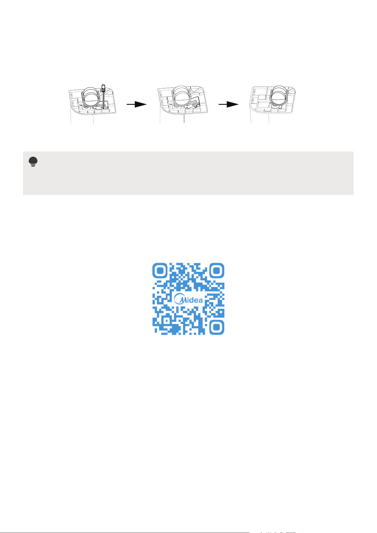
3. Pump draining (some models)
• Water can be pumped from the unit
into a sink or other type of drain by
putting the unit in pump mode and
attaching the included pump hose.
Be sure to install both the inlet and
outlet pump hoses as shown in the
figures on the right.
• To install the pump hose, remove the
plug from the pump drain hole and
firmly attach the included pump
hose as shown in Fig. 14.
• Holding the fill level button for 3
seconds will activate pump mode if
the bucket is in place (pump model only).
• The pump inlet hose must be
placed in the bucket in order to
pump the water out of the bucket.
pump drain
hose outlet
Reinstall the
plastic cover
pump
drain hose
pump drain hose
pump filter
outlet connection
pump drain hose
inlet connection
Fig. 14
Fig. 15
• Make sure the hose is secure so there are no leaks.
• Direct the hose toward the drain, making sure that there are no kinks that will stop
the water flowing.
• Place the end of the hose into the drain.
• Select the desired humidity setting and fan speed on the unit for pump draining
to start.
• When operating in Bucketless mode, the pump cannot be used.
NOTICE
disconnect the power cord. Check the following items:
• Cleaning the pump filter:
- Remove the bucket from the unit, rinse the filter of the pump with water or wipe it with a rag.
• Check if the drain hose is clean and free of debris.
• Empty the water from the bucket.
• Check the hose connection and the bucket for proper fitment. If the error persists, contact Customer
Service.
NOTICE
If routing the drain hose outdoors, do not operate when the outdoor temperature is at or below
32°F (0°C) as the water will freeze, blocking the hose and causing the unit to stop.
Make sure to empty the bucket at least once a week when using the pump draining feature.
When the pump draining feature is not being used, remove the pump drain hose from the outlet.
Clean the Grille and Case
CLEANING AND MAINTENANCE
Use water and a mild detergent. Do not use bleach or abrasives.
Do not splash water directly onto the unit. Doing so may cause
an electrical shock, cause the insulation to deteriorate, or cause
the unit to rust.
The air intake and outlet may get dirty during operation, use a
vacuum cleaner or brush to clean.
source before cleaning.
Every few weeks, clean the bucket thoroughly. Partially fill the
bucket with clean water and mild detergent. Swish it around in
the bucket, empty and rinse.
Note: Do not use a dishwasher to clean the bucket. After clean,
the bucket must be in place and securely seated for the
dehumidifier to operate.
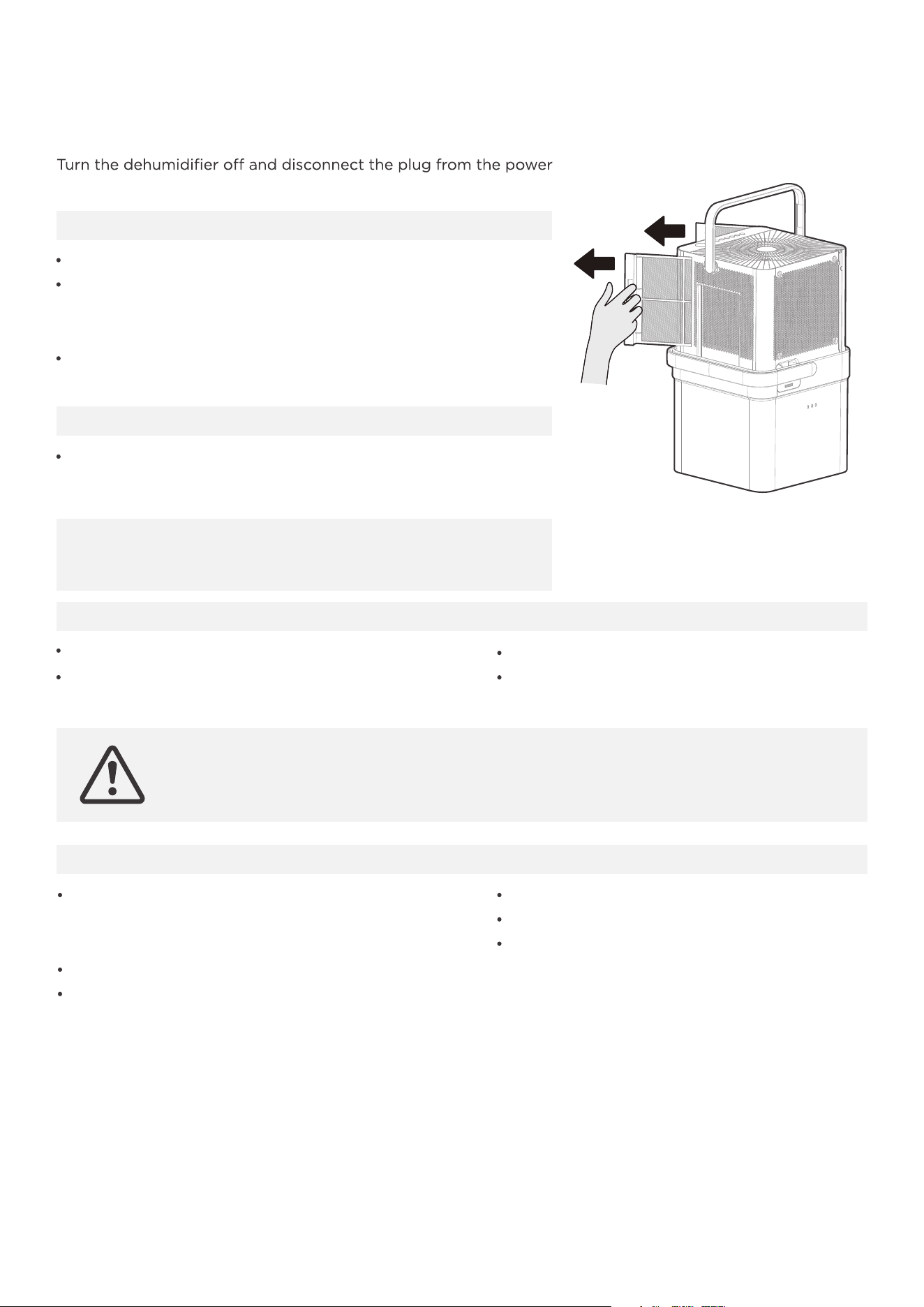
Clean the bucket
To remove the filters, pull each filter outwards.
Wash the filters with clean water then dry.
Re-install each filter.
Reset the filter indicator light following
operating instructions.
Clean the air filter
Filters on the left
and right sides
Nest the unit inside the bucket.
Cover the unit with a plastic bag.
Store the unit upright in a dry,
well-ventilated area.
CAUTION
To avoid loss of performance or damage to the unit, DO NOT operate the
dehumidifier without the filters.
Before storing the unit and bucket, let it
rest for one full day so that the system
can dry out naturally.
Clean the unit, water bucket and air filters.
Ensure the power cord is in the power
cord storage channel.
When not using the unit for long time periods
20
CAUTION
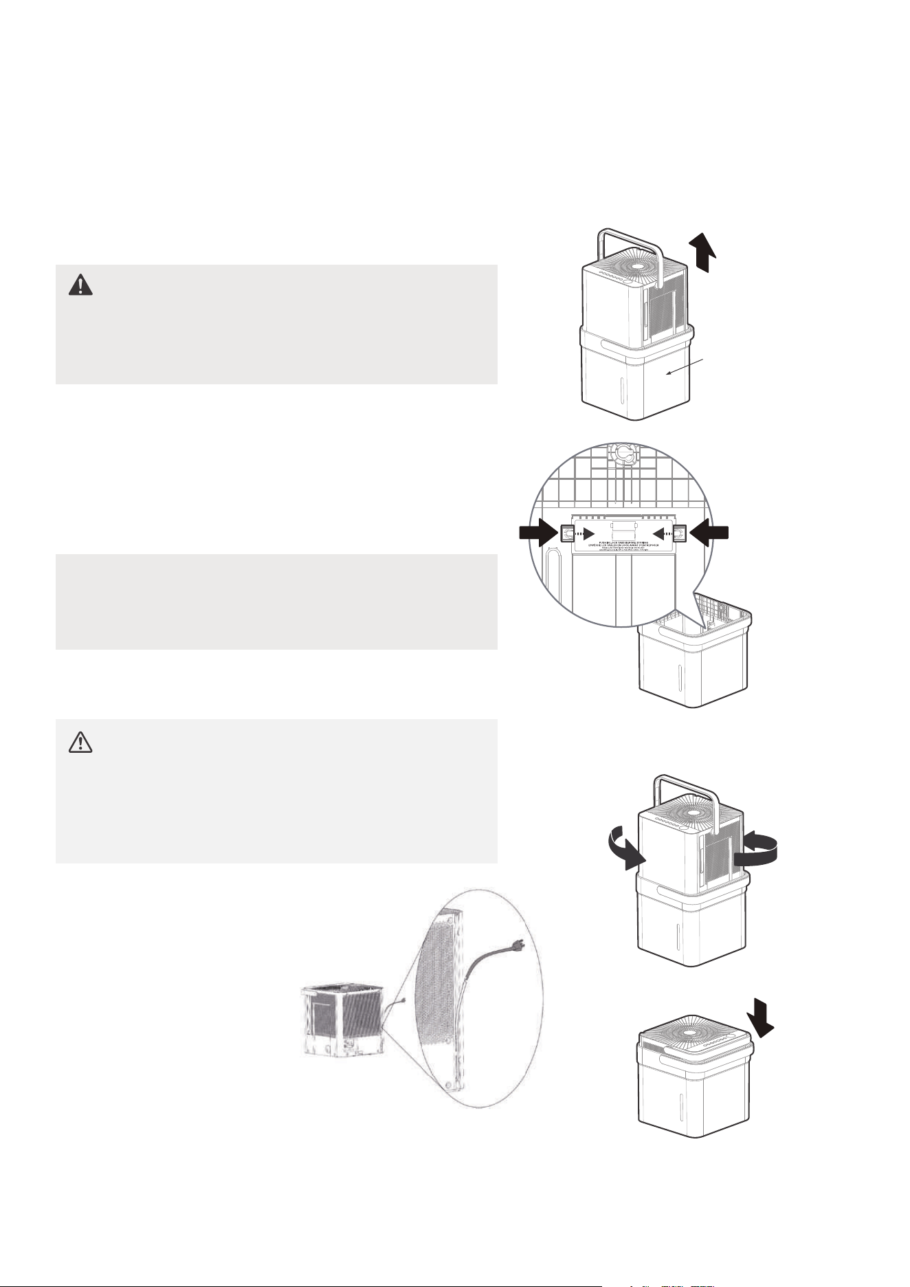
NESTING AND STORING INSTRUCTIONS
When carrying the nested unit, be sure
and use the bucket handle to ensure both
the dehumidifier and bucket are safely
carried.
Fig. 17
Fig. 18
Fig. 20
Fig. 19a
Fig. 19b
Step 1:
Power o and unplug the unit. Then lift the dehumidifier o
the bucket.
Step 2:
Empty all water from bucket.
Step 3:
Make sure to press the tabs on the inside bucket feature in
so that the unit can nest correctly. See Fig. 18.
Step 4:
Rotate dehumidifier 90° in either direction and insert into
bucket to nest.
Step 5:
The dehumidifier is nested and ready to store.
WARNING
Make sure the bucket is empty before
nesting the dehumidifier to avoid risk of
electrical shock.
Make sure
it is empty.
NOTICE
Make sure the power cord is properly tucked into the
power cord storage channel on the back of the
dehumidifier to prevent damage.
21

Unit does not
start
Make sure the dehumidifiers plug is connected firmly into the wall outlet.
Check the house fuse/circuit breaker box.
Dehumidifier has reached its preset level or bucket is full.
Water bucket is not in the proper position.
Not enough time to remove the moisture.
Make sure there are no curtains, blinds or furniture blocking the front
or back of the dehumidifier.
The humidity control may not be set low enough.
Check that all doors, windows and other openings are securely closed.
Room temperature is too low, below 5°C (41°F).
There is a water vapor source in the room.
Air filter may be dirty. Clean filter. Refer to Care and Cleaning section.
The unit is tilted instead of upright as it should be.
The floor surface is not level.
This is normal. The dehumidifier has Auto defrost feature.
Hose to connector or hose connection may be loose.
Intended to use the bucket to collect water, but the back drain plug is
removed.
These are error codes and protection code. Check Operating
Instructions.
Clean the pump filter.
Check the pump hose is not blocked or leaking.
Empty the water bucket.
Check to ensure the unit is level, and there is no debris on the surface.
Check the drain hose connection and ensure it is properly seated in
the outlet.
Dehumidifier
does not dry
the air as it
should
The unit makes
a loud noise
when operating
Frost appears
on the coils
Water on floor
EH60, EH61, P2,
EC, Eb and
EH0b appear
in the display
The pump
operation on
light blinks at
1Hz
When operating
in bucketless
mode, water
collects around
the bottom of the
unit
TROUBLESHOOTING TIPS
Problem What to check
Before calling for service, review this list as it may save time and money. This list includes common
occurrences that are not the result of defective workmanship or materials in this appliance.
22

23
APP INSTRUCTIONS
We hereby declare that this Dehumidifier is in compliance with the essential requirements and other
relevant provisions of Directive 1999/5/EC.
1. Supports operating systems: iOS 10+ or Android 5+.
2. In the event of an OS update, a delay may occur before the corresponding software update is available,
potentially affecting compatibility until a new version is released. Device-specific or network issues may
also impact the unit's functionality, and Midea disclaims responsibility for any resulting problems.
3. This Smart Dehumidifier only supports WPA-PSK/WPA2-PSK (recommended) encryption.
4. To ensure proper scanning of the QR code, the smartphone must have at least a 5-megapixel camera.
5. Due to unstable network connectivity, requests may time out. If this happens, rerun the network
configuration.
6. Due to unstable network connectivity, commands may time out. If this happens, the smartphone app and
the actual product may display conflicting information. The information displayed on the actual product
is always the most accurate. Refresh the app to re-sync.
DECLARATION OF CONFORMITY
SPECIFICATION OF WIRELESS MODULE
PRECAUTIONS
Wireless Module Model: US-SK105
Antenna Type: Printed PCB Antenna
Frequency Band: 2400-2483.5MHz
Operation Temperature: 0 C~45 C/32 F~113 F
Operation Humidity: 10%~85%
Power Input: DC 5V/300mA
Maximum TX Power: <20dBm
NOTICE
Midea will not be responsible for any problems that could be caused by incompatibility or network
issues, wireless router and mobile phone.
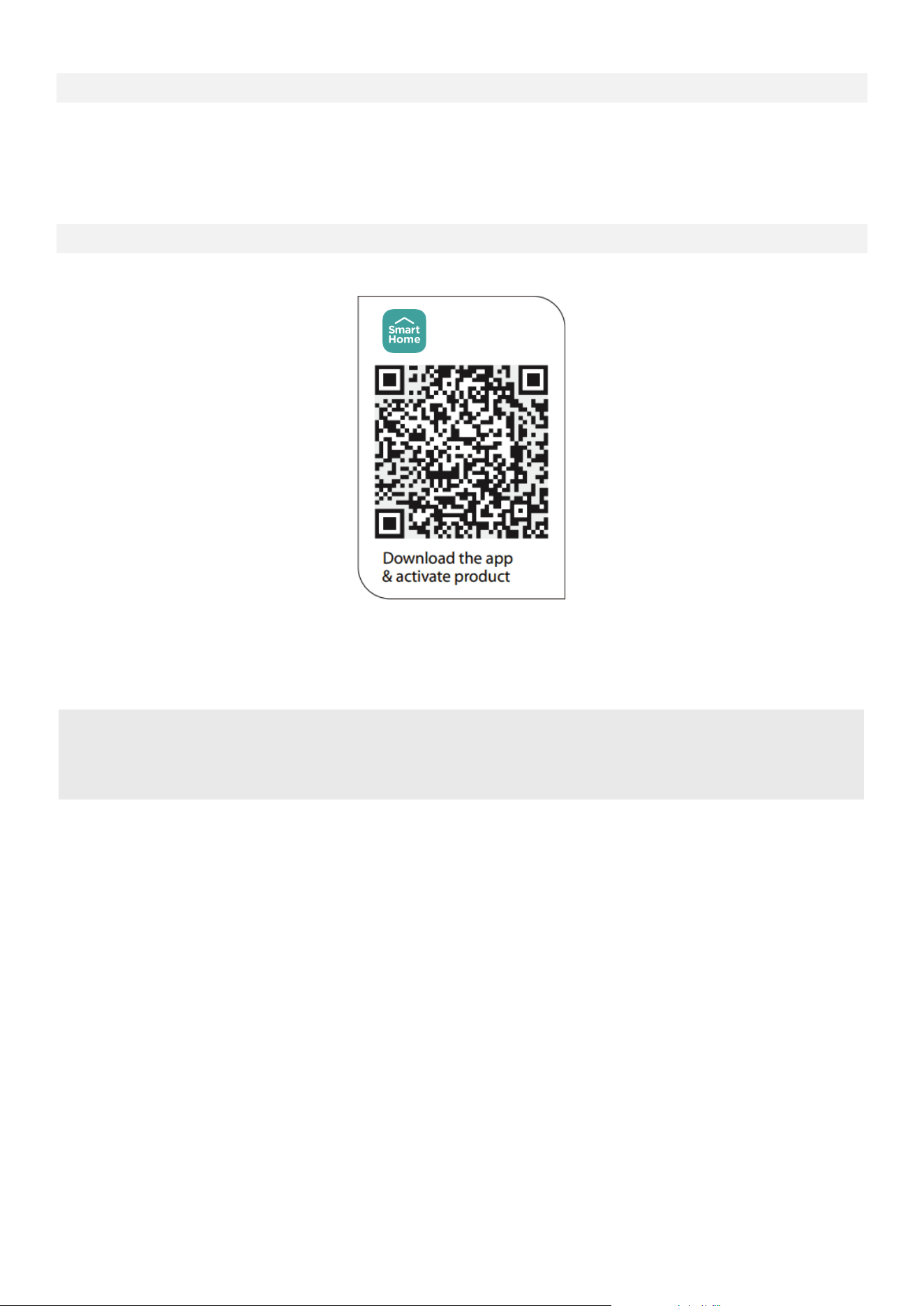
Scan to download app.
• App can also be downloaded from Google Play or App Store. Search for "SmartHome".
Devices required to use the Smart Dehumidifier:
1. Smart Phone with compatible iOS or Android system.
2. Wireless Router
3. Smart Dehumidifier
SYSTEM OVERVIEW
DOWNLOAD AND INSTALL THE APP
NOTICE
All the images in this manual are for reference only, the product and app may look slightly different.
The actual product and app instructions have to be considered.
24
SmartHome
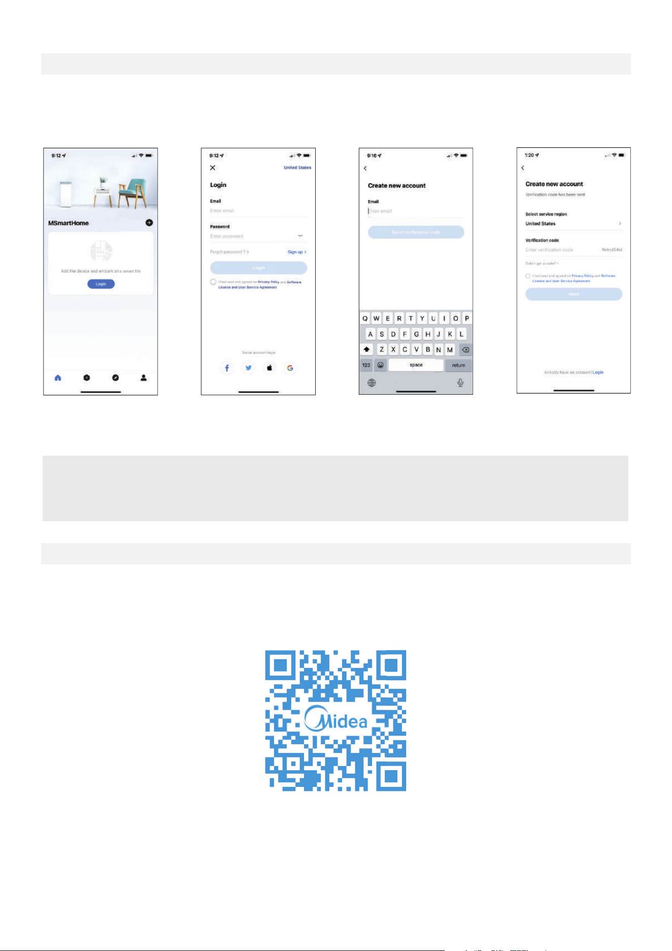
• Make sure the smartphone is connected to the correct wireless router and the wireless router has a
working 2.4 GHz internet connection.
• It is recommended to activate the account immediately to be able to recover the password by email.
1. Press Login. 2. Select Sign Up.
3. Enter email address.
4. Enter the verification
code sent to the
email address.
CREATE THE ACCOUNT
NOTICE
• Make sure the smartphone is able to connect to the wireless network which will be used.
• Make sure also that the device is not connected to other networks in range.
For additional instructions regarding the features of the app and Smart Home skill
capabilities, scan the QR code below.
ADDITIONAL APP AND SMART HOME FUNCTIONS
25
Declaration of conformity
NOTICE:
All the illustrations in the manual are for explanation purpose only. The unit may
prevail.
Company will not be liable for any issues and problems caused by Internet,
Wireless Router and Smart Devices. Please contact the original provider
to get further help.
FCC ID:2ADQOMDNA21
IC:12575A-MDNA21
This device complies with Part 15 of the FCC Rules and it contains licence
exempt transmitter(s)/receiver(s) that comply with Innovation, Science and
Economic Development Canada’s licence-exempt RSS(s).
Operation is subject to the following two conditions:
(1) This device may not cause harmful interference.
(2) This device must accept any interference, including interference that may
cause undesired operation of the device.
Only operate the device in accordance with the instructions supplied.
Changes or modifications to this unit not expressly approved by the party
responsible for compliance could void the user's authority to operate the equipment.
This device complies with radiation exposure limits set forth for an uncontrolled
environment. In order to avoid the possibility of exceeding the radio frequency
exposure limits, human proximity to the antenna shall not be less than 20cm
(8 inches) during normal operation.
Note: This equipment has been tested and found to comply with the limits for a
Class B digital device, pursuant to Part 15 of the FCC rules. These limits are
designed to provide reasonable protection against harmful interference in a
residential installation. This equipment generates, uses and can radiate radio
frequency energy and, if not installed and used in accordance with the instructions,
may cause harmful interference to radio communications. However there is no
guarantee that interference will not occur in a particular installation. If this
equipment does cause harmful interference to radio or television reception, which
to try to correct the interference by one or more of the following measures:
• Reorient or relocate the receiving antenna
• Increase the separation between the equipment and receiver
the receiver is connected
26
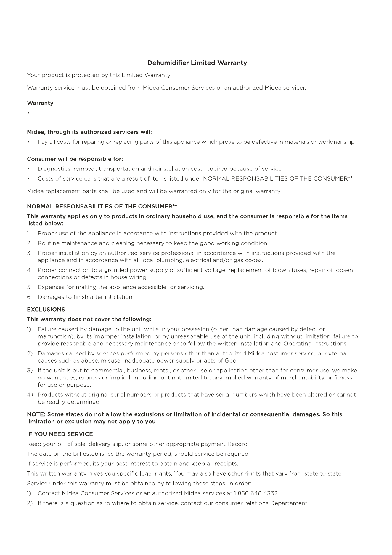
WARRANTY
27
One year limited warranty from the date of delivery or the purchase date, whichever is later.
The date of delivery establishes the warranty period, should service be required.
28
DISPOSAL AND RECYCLING
Important instructions for environment(European Disposal Guidelines)
Compliance with the WEEE Directive and Disposing of the Waster Product:
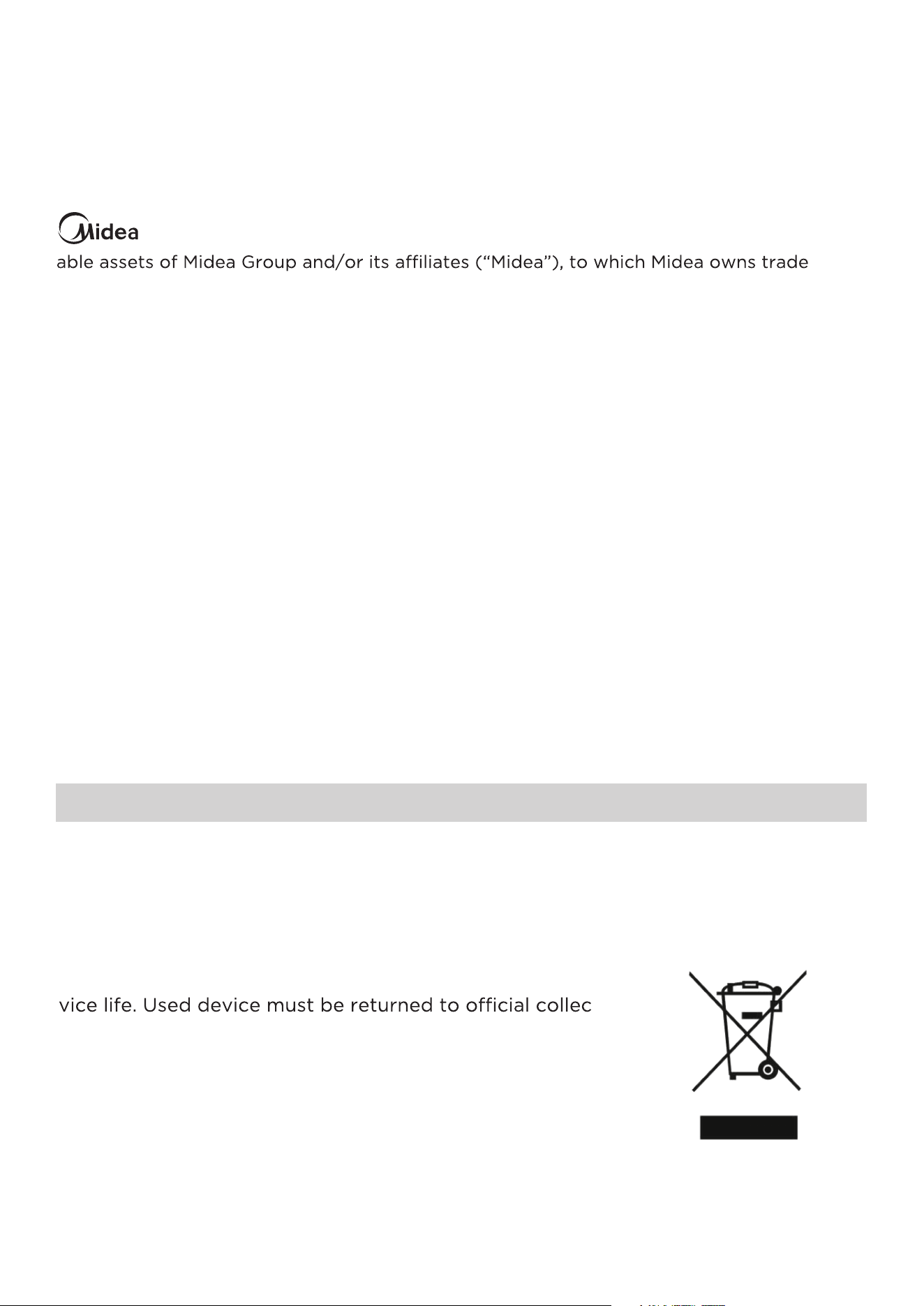
This product complies with EU WEEE Directive. This product bears a classification
symbol for waster electrical and electronic equipment (WEEE).
This symbol indicates that this product shall not be dis-
posed with other household wastes at the end of its ser-
-
tion point for recycling of electrical and electronic devices.
To find these collection systems, please contact to the local
authorities or retailer where the product was purchased.
Each household performs important role in recovering
and recycling of old appliance. Appropriate disposal of
used appliance helps prevent potential negative conse-
quences for the environment and human health.
logo, word marks, trade name, trade dress and all versions thereof are valu-
-
marks, copyrights and other intellectual property rights, and all goodwill derived from
using any part of an Midea trademark. Use of Midea trademark for commercial purposes
without the prior written consent of Midea may constitute trademark
infringement or unfair competition in violation of relevant laws.
This manual is created by Midea and Midea reserves all copyrights thereof. No entity or
individual may use, duplicate, modify, distribute in whole or in part this manual, or
bundle or sell with other products without the prior written consent of Midea.
All the described functions and instructions were up to date at the time of printing this
manual. However, the actual product may vary due to improved functions and designs.
TRADEMARKS, COPYRIGHTS
AND LEGAL STATEMENT

DATA PROTECTION NOTICE
For the provision of the services agreed with the customer,
we agree to comply without restriction with all stipulations of applicable data
protection law, in line with agreed countries within which services to the customer
will be delivered, as well as, where applicable, the EU General Data Protection
Regulation (GDPR).
Generally, our data processing is to fulfill our obligation under contract with you and
for product safety reasons, to safeguard your rights in connection with warranty
and product registration questions. In some cases, but only if appropriate data
protection is ensured, personal data might be transferred to recipients located
outside of the European Economic Area.
Further information are provided on request. You can contact our Data Protection
[email protected]. To exercise your rights such as right to object
your personal date being processed for direct marketing purposes, please contact
us via [email protected]. To find further information, please follow the QR
Code below.
The design and specifications are subject to change without prior notice for
product improvement. Consult with the sales agency or manufacturer for details.
Any updates to the manual will be uploaded to the service website, please check
for the latest version.
29


2025
16122000A82673
20251107
CD001UI-DM(NEW)A