Visit our website at: http://www.harborfreight.com
email our technical support at: [email protected]
59785
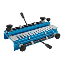
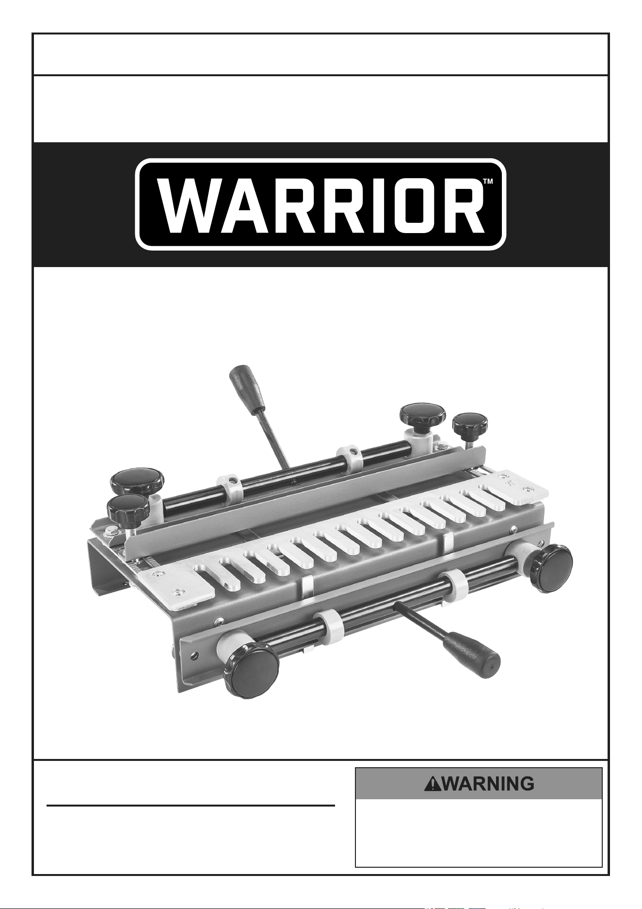
DOVETAIL JIG
Owner’s Manual & Safety Instructions
Save This Manual Keep this manual for the safety warnings and precautions, assembly,
operating, inspection, maintenance and cleaning procedures. Write the product’s serial number in the
back of the manual near the assembly diagram (or month and year of purchase if product has no number).
Keep this manual and the receipt in a safe and dry place for future reference. 23h
When unpacking, make sure that the product is intact
and undamaged. If any parts are missing or broken,
please call 1-888-866-5797 as soon as possible.
Copyright
©
2023 by Harbor Freight Tools
®
. All rights reserved.
No portion of this manual or any artwork contained herein may be reproduced in
any shape or form without the express written consent of Harbor Freight Tools.
Diagrams within this manual may not be drawn proportionally. Due to continuing
improvements, actual product may differ slightly from the product described herein.
Tools required for assembly and service may not be included.
read this material before using this product.
Failure to do so can result in serious injury.
SaVe tHiS ManuaL.

Page 2 For technical questions, please call 1-888-866-5797. Item 59785
SaFety OperatiOn MaintenanceSetup
table of contents
Safety ......................................................... 2
Specifications ............................................. 3
Setup .......................................................... 3
Operation .................................................... 9
Maintenance .............................................. 10
Parts List and Diagram .............................. 11
Warranty .................................................... 12
iMpOrtant SaFety inFOrMatiOn
General Safety Warnings and precautions
1. KEEP WORK AREA CLEAN AND DRY. Cluttered,
damp, or wet work areas invite injuries.
2. KEEP CHILDREN AWAY FROM WORK AREA.
Do not allow children to handle this product.
3. STORE IDLE EQUIPMENT. When not in use,
tools and equipment should be stored in a dry
location to inhibit rust. Always lock up tools and
equipment, and keep out of reach of children.
4. DO NOT USE THIS PRODUCT IF UNDER
THE INFLUENCE OF ALCOHOL OR DRUGS.
Read warning labels on prescriptions to
determine if your judgement or reflexes are
impaired while taking drugs. If there is any
doubt, do not attempt to use this product.
5. USE EYE AND BREATHING PROTECTION.
Wear ANSI approved safety impact eye goggles
and an ANSI approved dust mask or respirator
when using this product. ANSI approved safety
impact eye goggles, dust masks, and respirators
are available from Harbor Freight Tools.
6. DRESS SAFELY. Do not wear loose clothing or
jewelry, as they can become caught in moving parts.
Wear a protective hair covering to prevent long hair
from becoming caught in moving parts. If wearing
a long-sleeve shirt, roll sleeves up above elbows.
7. DO NOT OVERREACH. Keep proper
footing and balance at all times to prevent
tripping, falling, back injury, etcetera.
8. INDUSTRIAL APPLICATIONS MUST
FOLLOW OSHA REQUIREMENT.
9. STAY ALERT. Watch what you are doing at all times.
Use common sense. Do not use this product when
you are tired or distracted from the job at hand.
10. CHECK FOR DAMAGED PARTS. Before using
this product, carefully check that it will operate
properly and perform its intended function. Check
for damaged parts and any other conditions that
may affect the operation of this product. Replace
or repair damaged or worn parts immediately.
11. MAINTAIN THIS PRODUCT WITH
CARE. Keep this product clean and dry
for better and safer performance.
12. USE THE RIGHT TOOL FOR THE JOB. Do
not attempt to force a small tool or attachment
to do the work of a larger industrial tool. There
are certain applications for which this tool was
designed. It will do the job better and more
safely at the rate for which it was intended. Do
not modify this tool, and do not use this tool
for a purpose for which it was not intended.
13. WARNING: The warnings, precautions, and
instructions discussed in this manual cannot cover
all possible conditions and situations that may occur.
The operator must understand that common sense
and caution are factors, which cannot be built into
this product, but must be supplied by the operator.
Specific product Warnings and precautions
1. USE THE PROPER DOVETAIL BIT FOR YOUR
ROUTER. For use only with Ø1/4" shank,
Ø1/2" x 14° dovetail bits (sold separately).
Do not use a bit larger than recommended,
or damage to the Template will result.
2. MAINTAIN A SAFE WORKING ENVIRONMENT.
Keep the work area well lit. Make sure there
is adequate surrounding workspace. Always
keep the work area free of obstructions,
grease, oil, trash, and other debris.
SaVe tHeSe inStructiOnS.
Page 3For technical questions, please call 1-888-866-5797.Item 59785
SaFetyOperatiOnMaintenance Setup
Specifications
Dovetail Jig Style 1/2" Half-Blind Joints
Workpiece Capacity 1-1/4" Thick and 10" Wide
Router Requirements
1/4" Collet, 7" max Base,
7/16" Template Guide (sold separately)
Router Dovetail Bit Ø1/4" Shank, Ø1/2" x 14° (sold separately)
Setup - Before use:
read the entire iMpOrtant SaFety inFOrMatiOn section at the beginning of this document
including all text under subheadings therein before set up or use of this product.
note: For additional information regarding the parts listed in the following pages,
refer to the Assembly Diagram near the end of this manual.
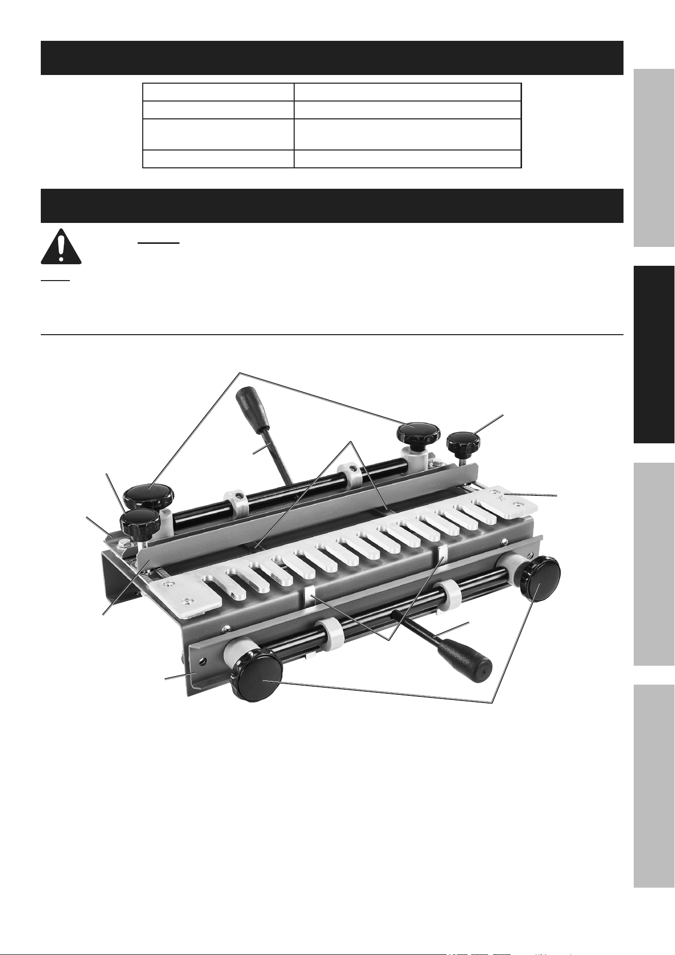
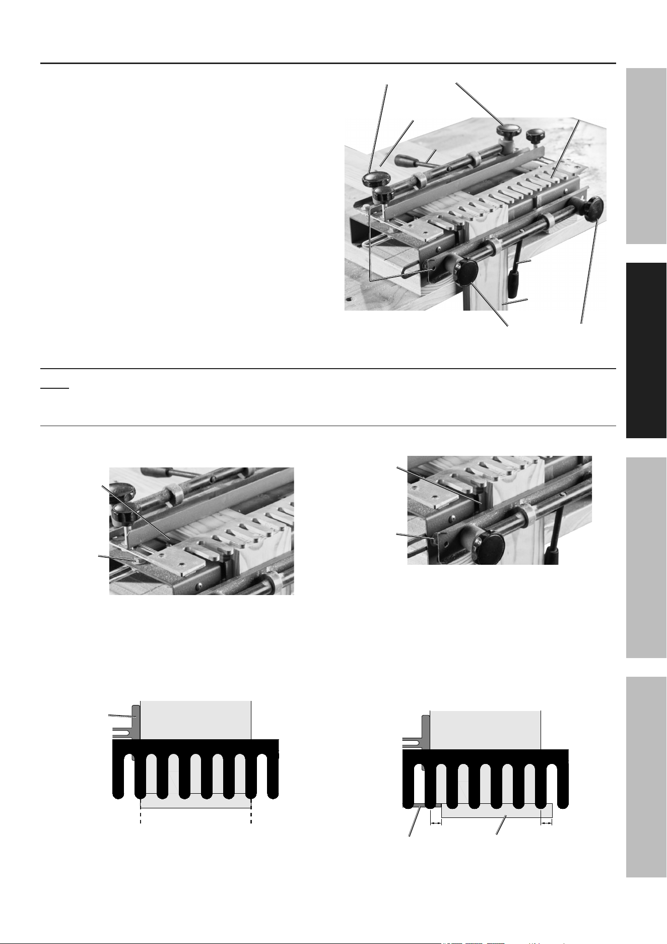
Functions
Fence
top
clamp Knobs
Front
Lever
top
Lever
template
Fence
Knob
Fence
Knob
Front
clamp Knobs
Front
clamp
top
clamp
top
Stops
Front
Stops
template - Pattern for cutting dovetails
Fence - Router guide
Fence Knobs - Hold Fence in place
Levers - Hold workpieces in place
clamp Knobs - Adjust Clamp pressure
Stops - Align workpieces to Template
Page 4 For technical questions, please call 1-888-866-5797. Item 59785
SaFety OperatiOn MaintenanceSetup
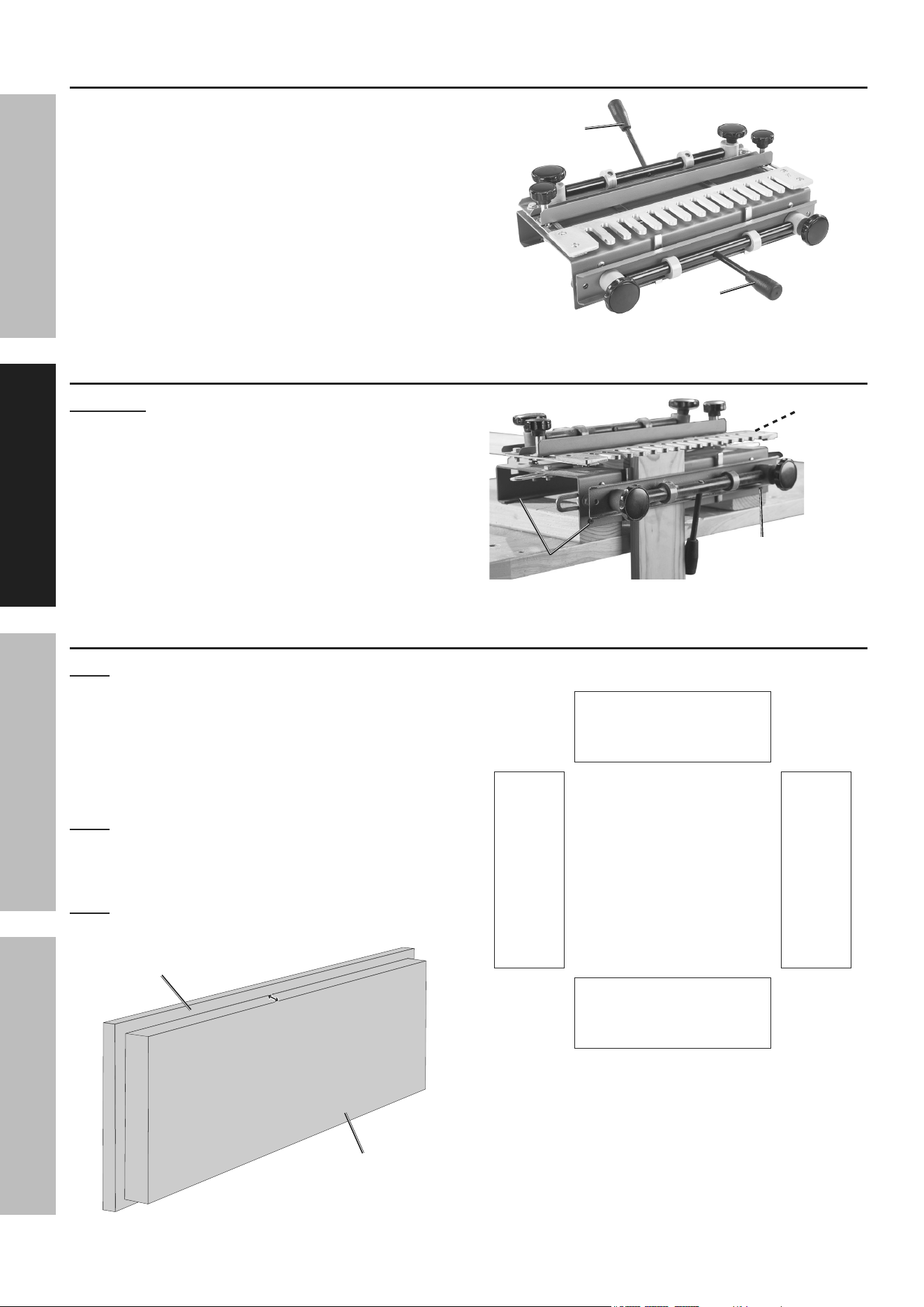
assembly
Thread Levers into Rods.
Front
Lever
top
Lever
Mounting
cautiOn! tO preVent inJury Or
prOperty DaMaGe: Mount the Jig on a
flat, level, sturdy, surface capable of supporting
the weight of Jig, workpieces, and tools.
1. Position Jig on front edge of mounting surface.
2. Using Jig as a template, mark and drill four
holes in mounting surface. Secure Jig with
appropriate hardware (not included).
Mounting
Mounting
Holes
Holes
Mounting
Mounting
Hole
Hole
Mounting
Mounting
Hole
Hole
preparing Workpieces
note: Prepare two identical sets of workpieces.
Use scrap material for one set for test cutting.
1. Cut front and back workpieces minimum
5/8" thick and 1" increments wide.
2. Cut Side workpieces minimum 3/8" thick
and 1" increments wide.
note: Difference in thickness between front,
back and sides must be 1/4" or less.
3. Verify all workpiece edges are flat, even and square.
note: If using rabbeted front, interior
face must be minimum 5/8" thick.
rabbet notch
interior
Face
5/8
5/8
"
"
4. Mark inside of workpieces with names and numbers.
inside Front
inside Back
inside right
inside Left
12
3 4
12
3 4
Page 5For technical questions, please call 1-888-866-5797.Item 59785
SaFetyOperatiOnMaintenance Setup
Setting clamp pressure
1. Open Levers (shown closed).
2. Loosen Clamp Knobs.
3. With markings facing out, mount side workpiece
vertically, flush against Template. Tighten Clamp
Knobs until Clamp just touches workpiece.
4. Close Front Lever.
5. With markings facing out and matching number
next to vertical workpiece, mount front or back
workpiece horizontally under Template and
flush against vertical workpiece. Tighten Clamp
Knobs until Clamp just touches workpiece.
6. Close Top Lever.
7. Check workpieces and Template for
flexing or raising. Adjust Clamp Knobs as
necessary until workpieces are flat.
Vertical Vertical
WorkpieceWorkpiece
Horizontal Horizontal
WorkpieceWorkpiece
clamp Knobsclamp Knobs
toptop
LeverLever
clampsclamps
FrontFront
LeverLever
template
11
SideSide
clamp Knobsclamp Knobs
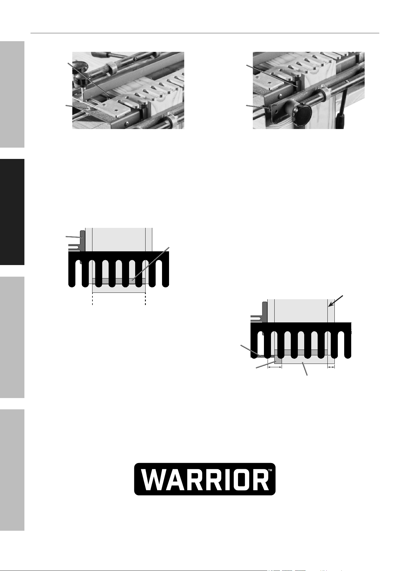
adjusting Stops
note: These instructions are for processing one set of joints. Two sets may be processed
using all four Stops, if combined width of workpieces is less than 10".
Standard Front and Back
1. Loosen Top Stop Bolt with 12mm
wrench (sold separately).
toptop
StopStop
StopStop
BoltBolt
2. Open Top Lever and center horizontal (front/back)
workpiece under Template fingers and flush against
vertical workpiece.
3. Close Top Lever.
4. Slide Top Stop against workpiece and
tighten Stop Bolt; do not overtighten.
HorizontalHorizontal
WorkpieceWorkpiece
Vertical WorkpieceVertical Workpiece
top
Stop
5. Loosen Front Stop Bolt.
StopStop
BoltBolt
FrontFront
StopStop
6. Measure 1/2" to right from right edge of
horizontal workpiece and mark rear edge
of template. Open Front Lever and align
right edge of vertical (side) workpiece
to mark on template, keeping it flush to
Template and horizontal workpiece.
7. Close Front Lever.
8. Slide Front Stop against workpiece and
tighten Stop Bolt; do not overtighten.
1/2" 1/2"
HorizontalHorizontal
WorkpieceWorkpiece
Vertical WorkpieceVertical Workpiece
Front Stop
9. Verify vertical workpiece is flush against
horizontal workpiece and Template.
Page 6 For technical questions, please call 1-888-866-5797. Item 59785
SaFety OperatiOn MaintenanceSetup
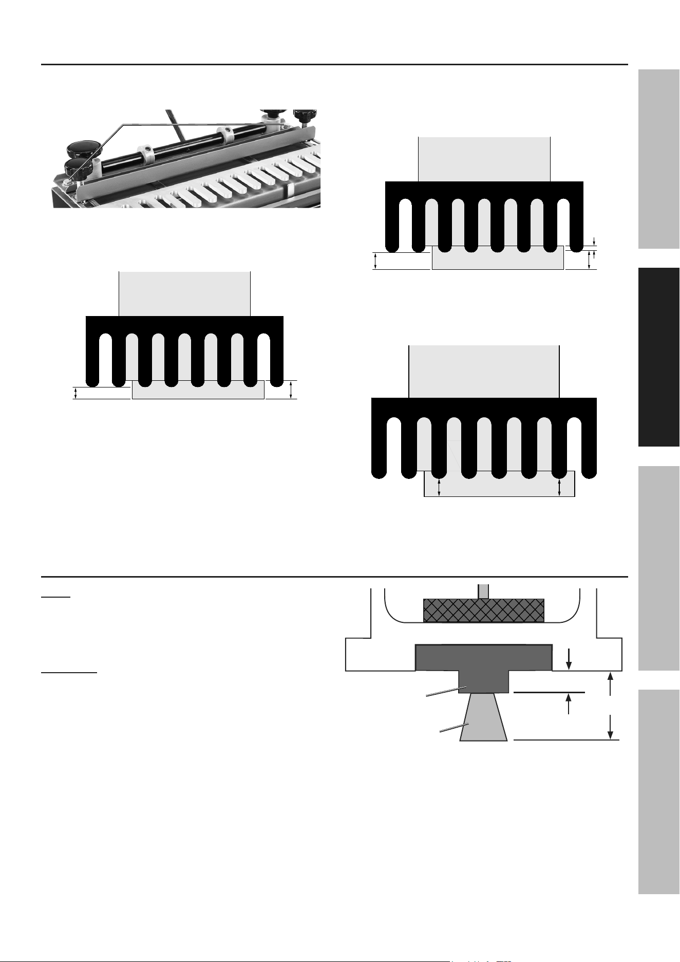
rabbeted Front and Standard Back
1. Loosen Top Stop Bolt.
toptop
StopStop
StopStop
BoltBolt
2. Open Top Lever and center horizontal (front/back)
workpiece under Template and flush against
vertical workpiece.
3. Close Top Lever.
4. Slide Top Stop against workpiece and
tighten Stop Bolt; do not overtighten.
5. Cut top spacer for horizontal workpiece
the same width as side rabbet notch and
insert behind vertical workpiece.
HorizontalHorizontal
WorkpieceWorkpiece
Vertical Vertical
WorkpieceWorkpiece
top
Stop
top
Spacer
6. Loosen Front Stop Bolt.
StopStop
BoltBolt
FrontFront
StopStop
7. Cut bottom spacer for vertical workpiece
the same width as top rabbet notch.
8. Measure 1/2" to right from right rabbeted
edge of horizontal workpiece and
mark rear edge of template.
9. Open Front Lever and insert bottom spacer
between vertical (side) workpiece and Front
Stop, keeping it flush to vertical workpiece.
10. Move spacer and vertical workpiece to the right,
aligning edge to mark on template, keeping them
flush to Template and horizontal workpiece.
11. Close Front Lever.
12. Slide Front Stop against bottom spacer and
tighten Stop Bolt; do not overtighten.
1/2" +
Spacer
HorizontalHorizontal
WorkpieceWorkpiece
Vertical Vertical
WorkpieceWorkpiece
Front
Stop
Bottom
Spacer
1/2"
rabbeted
edge
13. Verify vertical workpiece is flush against horizontal
workpiece, top spacer, and Template.
Page 7For technical questions, please call 1-888-866-5797.Item 59785
SaFetyOperatiOnMaintenance Setup
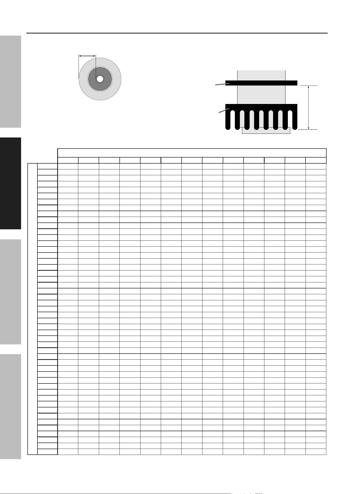
adjusting template
1. Slightly loosen Template Bolts with 12mm wrench.
template
Bolts
2. Vertical workpiece less than or equal to
7/8" thick: Slide Template so front edge
is 1/8" back from workpiece edge.
1/8"
7/8" or
Less
3. Vertical workpiece more than 7/8" thick:
Determine amount thickness exceeds 7/8" (X),
and add 1/8". Set Template front edge back
from vertical workpiece edge by that amount.
X+1/8"
7/8"
X
4. Measure at both ends of workpiece
to verify Template is parallel to front
edge of vertical workpiece.
5. Tighten Template Bolts , then reverify Template
is parallel to front edge of vertical workpiece.
Setting up router
note: Reference Specifications on page 3 for router
base, dovetail bit and template guide requirements.
1. Refer to router manual's instructions for
installing router bit and template guide.
cautiOn! tO preVent inJury Or
prOperty DaMaGe: DO nOt uSe
teMpLate GuiDe if it protrudes less than
1/8" or more than 3/16" below router base.
2. Using combination square (sold separately), adjust
dovetail bit so it protrudes 9/16" below router base.
3. Confirm template guide and dovetail bit are secure.
9/16"
1/8" to 3/16"
router Base
template template
GuideGuide
DovetailDovetail
BitBit
templatetemplate
GuideGuide
Page 8 For technical questions, please call 1-888-866-5797. Item 59785
SaFety OperatiOn MaintenanceSetup
adjusting Fence
1. Using a combination square measure distance
from template guide edge to router base edge.
2. Measure vertical workpiece thickness. For rabbeted
fronts, add top spacer width to workpiece thickness.
3. Look up value from Fence Adjustment
Table on page 8.
4. Loosen Fence Knobs, set distance between
Template front edge and Fence, then tighten Knobs.
5. Measure at both ends and verify Fence
is parallel with Template front edge.
templatetemplate
FenceFence
table Value
Fence adjustment table
Vertical Workpiece thickness in inches
1/2 17/32 9/16 19/32 5/8 21/32 11/16 23/32 3/4 25/32 13/16 27/32 7/8
Distance from template Guide edge to router Base edge in inches
2 2-13/16 2-7/8 2-15/16 3 3-1/16 3-1/8 3-3/16 3-1/4 3-5/16 3-3/8 3-7/16 3-1/2 3-9/16
2-1/32 2-27/32 2-29/32 2-31/32 3-1/32 3-3/32 3-5/32 3-7/32 3-9/32 3-11/32 3-13/32 3-15/32 3-17/32 3-19/32
2-1/16 2-7/8 2-15/16 3 3-1/16 3-1/8 3-3/16 3-1/4 3-5/16 3-3/8 3-7/16 3-1/2 3-9/16 3-5/8
2-3/32 2-29/32 2-31/32 3-1/32 3-3/32 3-5/32 3-7/32 3-9/32 3-11/32 3-13/32 3-15/32 3-17/32 3-19/32 3-21/32
2-1/8 2-15/16 3 3-1/16 3-1/8 3-3/16 3-1/4 3-5/16 3-3/8 3-7/16 3-1/2 3-9/16 3-5/8 3-11/16
2-5/32 2-31/32 3-1/32 3-3/32 3-5/32 3-7/32 3-9/32 3-11/32 3-13/32 3-15/32 3-17/32 3-19/32 3-21/32 3-23/32
2-3/16 3 3-1/16 3-1/8 3-3/16 3-1/4 3-5/16 3-3/8 3-7/16 3-1/2 3-9/16 3-5/8 3-11/16 3-3/4
2-7/32 3-1/32 3-3/32 3-5/32 3-7/32 3-9/32 3-11/32 3-13/32 3-15/32 3-17/32 3-19/32 3-21/32 3-23/32 3-25/32
2-1/4 3-1/16 3-1/8 3-3/16 3-1/4 3-5/16 3-3/8 3-7/16 3-1/2 3-9/16 3-5/8 3-11/16 3-3/4 3-13/16
2-9/32 3-3/32 3-5/32 3-7/32 3-9/32 3-11/32 3-13/32 3-15/32 3-17/32 3-19/32 3-21/32 3-23/32 3-25/32 3-27/32
2-5/16 3-1/8 3-3/16 3-1/4 3-5/16 3-3/8 3-7/16 3-1/2 3-9/16 3-5/8 3-11/16 3-3/4 3-13/16 3-7/8
2-11/32 3-5/32 3-7/32 3-9/32 3-11/32 3-13/32 3-15/32 3-17/32 3-19/32 3-21/32 3-23/32 3-25/32 3-27/32 3-29/32
2-3/8 3-3/16 3-1/4 3-5/16 3-3/8 3-7/16 3-1/2 3-9/16 3-5/8 3 -1/16 3-3/4 3-13/16 3-7/8 3-15/16
2-13/32 3-7/32 3-9/32 3-11/32 3-13/32 3-15/32 3-17/32 3-19/32 3-21/32 3-23/32 3-25/32 3-27/32 3-29/32 3-31/32
2-7/16 3-1/4 3-5/16 3-3/8 3-7/16 3-1/2 3-9/16 3-5/8 3-11/16 3-3/4 3-13/16 3-7/8 3-15/16 4
2-15/32 3-9/32 3-11/32 3-13/32 3-15/32 3-17/32 3-19/32 3-21/32 3-23/32 3-25/32 3-27/32 3-29/32 3-31/32 4-1/32
2-1/2 3-5/16 3-3/8 3-7/16 3-1/2 3-9/16 3-5/8 3-11/16 3-3/4 3-13/16 3-7/8 3-15/16 4 4-1/16
2-17/32 3-11/32 3-13/32 3-15/32 3-17/32 3-19/32 3-21/32 3-23/32 3-25/32 3-27/32 3-29/32 3-31/32 4-1/32 4-3/32
2-9/16 3-3/8 3-7/16 3-1/2 3-9/16 3-5/8 3-11/16 3-3/4 3-13/16 3-7/8 3-15/16 4 4-1/16 4-1/8
2-19/32 3-13/32 3-15/32 3-17/32 3-19/32 3-21/32 3-23/32 3-25/32 3-27/32 3-29/32 3-31/32 4-1/32 4-3/32 4-5/32
2-5/8 3-7/16 3-1/2 3-9/16 3-5/8 3-11/16 3-3/4 3-13/16 3-7/8 3-15/16 4 4-1/16 4-1/8 4-3/16
2-21/32 3-15/32 3-17/32 3-19/32 3-21/32 3-23/32 3-25/32 3-27/32 3-29/32 3-31/32 4-1/32 4-3/32 4-5/32 4-7/32
2-11/16 3-1/2 3-9/16 3-5/8 3-11/16 3-3/4 3-13/16 3-7/8 3-15/16 4 4-1/16 4-1/8 4-3/16 4-1/4
2-23/32 3-17/32 3-19/32 3-21/32 3-23/32 3-25/32 3-27/32 3-29/32 3-31/32 4-1/32 4-3/32 4-5/32 4-7/32 4-9/32
2-3/4 3-9/16 3-5/8 3-11/16 3-3/4 3-13/16 3-7/8 3-15/16 4 4-1/16 4-1/8 4-3/16 4-1/4 4-5/16
2-25/32 3-19/32 3-21/32 3-23/32 3 -5/32 3-27/32 3-29/32 3-31/32 4-1/32 4-3/32 4-5/32 4-7/32 4-9/32 4-11/32
2-13/16 3-5/8 3-11/16 3-3/4 3-13/16 3-7/8 3-15/16 4 4-1/16 4-1/8 4-3/16 4-1/4 4-5/16 4-3/8
2-27/32 3-21/32 3-23/32 3-25/32 3-27/32 3-29/32 3-31/32 4-1/32 4-3/32 4-5/32 4-7/32 4-9/32 4-11/32 4-13/32
2-7/8 3-11/16 3-3/4 3-13/16 3-7/8 3-15/16 4 4-1/16 4-1/8 4-3/16 4-1/4 4-5/16 4-3/8 4-7/16
2-29/32 3-23/32 3-25/32 3-27/32 3-29/32 3-31/32 4-1/32 4-3/32 4-5/32 4-7/32 4-9/32 4-11/32 4-13/32 4-15/32
2-15/16 3-3/4 3-13/16 3-7/8 3-15/16 4 4-1/16 4-1/8 4-3/16 4-1/4 4-5/16 4-3/8 4-7/16 4-1/2
2-31/32 3-25/32 3-27/32 3-29/32 3-31/32 4-1/32 4-3/32 4-5/32 4-7/32 4-9/32 4-11/32 4-13/32 4-15/32 4-17/32
3 3-13/16 3-7/8 3-15/16 4 4-1/16 4-1/8 4-3/16 4-1/4 4-5/16 4-3/8 4-7/16 4-1/2 4-9/16
3-1/32 3-27/32 3-29/32 3 -1/32 4-1/32 4-3/32 4-5/32 4-7/32 4-9/32 4-11/32 4-13/32 4-15/32 4-17/32 4-19/32
3-1/16 3-7/8 3-15/16 4 4-1/16 4-1/8 4-3/16 4-1/4 4-5/16 4-3/8 4-7/16 4-1/2 4-9/16 4-5/8
3-3/32 3-29/32 3 -1/32 4-1/32 4-3/32 4-5/32 4-7/32 4-9/32 4-11/32 4-13/32 4-15/32 4-17/32 4-19/32 4-21/32
3-1/8 3-15/16 4 4-1/16 4-1/8 4-3/16 4-1/4 4-5/16 4-3/8 4-7/16 4-1/2 4-9/16 4-5/8 4-11/16
3-5/32 3-31/32 4-1/32 4-3/32 4-5/32 4-7/32 4-9/32 4-11/32 4-13/32 4-15/32 4-17/32 4-19/32 4-21/32 4-23/32
3-3/16 4 4-1/16 4-1/8 4-3/16 4-1/4 4-5/16 4-3/8 4-7/16 4-1/2 4-9/16 4-5/8 4-11/16 4-3/4
3-7/32 4-1/32 4-3/32 4-5/32 4-7/32 4-9/32 4-11/32 4-13/32 4-15/32 4-17/32 4-19/32 4-21/32 4-23/32 4-25/32
3-1/4 4-1/16 4-1/8 4-3/16 4-1/4 4-5/16 4-3/8 4-7/16 4-1/2 4-9/16 4-5/8 4-11/16 4-3/4 4-13/16
3-9/32 4-3/32 4-5/32 4-7/32 4-9/32 4-11/32 4-13/32 4-15/32 4-17/32 4 -9/32 4-21/32 4-23/32 4-25/32 4-27/32
3-5/16 4-1/8 4-3/16 4-1/4 4-5/16 4-3/8 4-7/16 4-1/2 4-9/16 4-5/8 4-11/16 4-3/4 4-13/16 4-7/8
3-11/32 4-5/32 4-7/32 4-9/32 4-11/32 4-13/32 4-15/32 4-17/32 4-19/32 4-21/32 4-23/32 4-25/32 4-27/32 4-29/32
3-3/8 4-3/16 4-1/4 4-5/16 4-3/8 4-7/16 4-1/2 4-9/16 4-5/8 4-11/16 4-3/4 4-3/16 4-7/8 4-15/16
3-13/32 4-7/32 4-9/32 4-11/32 4-13/32 4-15/32 4-17/32 4-19/32 4-21/32 4-23/32 4-25/32 4-27/32 4-29/32 4-31/32
3-7/16 4-1/4 4-5/16 4-3/8 4-7/16 4-1/2 4-9/16 4-5/8 4-11/16 4-3/4 4-13/16 4-7/8 4-15/16 5
3-15/32 4-9/32 4-11/32 4-13/32 4-15/32 4-17/32 4-19/32 4-21/32 4-23/32 4-25/32 4-27/32 4-29/32 4-31/32 5-1/32
3-1/2 4-5/16 4-3/8 4-7/16 4-1/2 4-9/16 4-5/8 4 -1/16 4-3/4 4-13/16 4-7/8 4-15/16 5 5-1/16
Page 9For technical questions, please call 1-888-866-5797.Item 59785
SaFetyOperatiOnMaintenance Setup
Operating instructions
read the entire iMpOrtant SaFety inFOrMatiOn section at the beginning of this
manual including all text under subheadings therein before set up or use of this product.
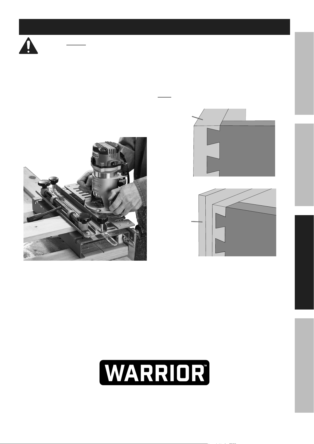
1. Plug router into 120VAC grounded outlet.
2. Place router on Template; confirm router
bit is not contacting workpieces.
3. Test cut on scrap workpieces and make adjustments
according to Troubleshooting on page 10.
4. Turn on router; let it come up to speed.
5. Making multiple passes, remove material from
in front of Template, then remove material inside
Template fingers until router contacts Fence.
6. When finished, turn off and unplug router.
7. Sand off rough edges that may interfere with
joint fit. A hammer and wood block may be
required to assemble workpieces together.
note: When assembled correctly, half-blind joints
will be flush to each other on all outside surfaces.
pinpin
tailtail
DrawerDrawer
FrontFront
SideSide
tailtail
Standard Front
tailtail
pinpin
DrawerDrawer
FrontFront
SideSide
tailtail
rabbet Front
8. Continue cutting and assembling vertical and
horizontal workpieces until all cuts are finished.
Page 10 For technical questions, please call 1-888-866-5797. Item 59785
SaFety OperatiOn MaintenanceSetup
Maintenance and Servicing
procedures not specifically explained in this manual must
be performed only by a qualified technician.
1. BeFOre eacH uSe, inspect the general
condition of the tool. Check for:
• loose hardware,
• misalignment or binding of moving parts,
• cracked or broken parts,
• any other condition that may
affect its safe operation.
2. aFter uSe, wipe external surfaces
of the tool with clean cloth.
troubleshooting
problem possible causes Likely Solutions
Rough edges / splintering /
tear outs when router
bit exits workpiece.
1. Forcing tool to work too fast.
2. Cutting across grain of wood.
1. Allow tool to work at its own rate.
2. Scribe a line on vertical workpiece at
same distance down router bit is cutting,
or back up workpiece with a scrap piece,
or slow router when exiting wood.
Pins on side piece fit
too deep in tails of
front / back piece.
Distance between edge
of vertical workpiece and
Fence is set too deep.
Adjust Fence forward by same
amount that pins are exposed. See
Adjusting Fence on page 8.
Pins on side piece protrudes
from tails of front / back piece.
Distance between edge
of vertical workpiece and
Fence is set too narrow.
Adjust Fence back by same
amount that tails protrude out. See
Adjusting Fence on page 8.
Side and front / back piece
edges are not aligned.
Stops are not set correctly. Measure offset amount of workpieces
and adjust Front Stops accordingly. Front
Stops must be offset from top Stops by
exact 1/2". Confirm front Stops remain
square to horizontal workpiece.
Fit too tight / loose. Depth of router bit needs adjustment. Fit to tight: Lower bit
slightly (1/64" - 1/32").
Fit to loose: Raise bit
slightly (1/64" - 1/32").
Side workpiece fits
excessively / protrudes at
one edge and not the other.
1. Workpiece edges are not parallel
with Template front edge.
2. Fence is not parallel with
Template front edge.
3. Template is not parallel
with workpiece edges.
1. Clamp workpieces parallel to each
other and tight against Stops.
2. Adjust Fence parallel to front
edge of Template fingers.
3. Adjust Template parallel to front
edges of workpieces.
Follow all safety precautions whenever diagnosing or servicing the tool.
record product’s Serial number Here:
note: if product has no serial number, record month and year of purchase instead.
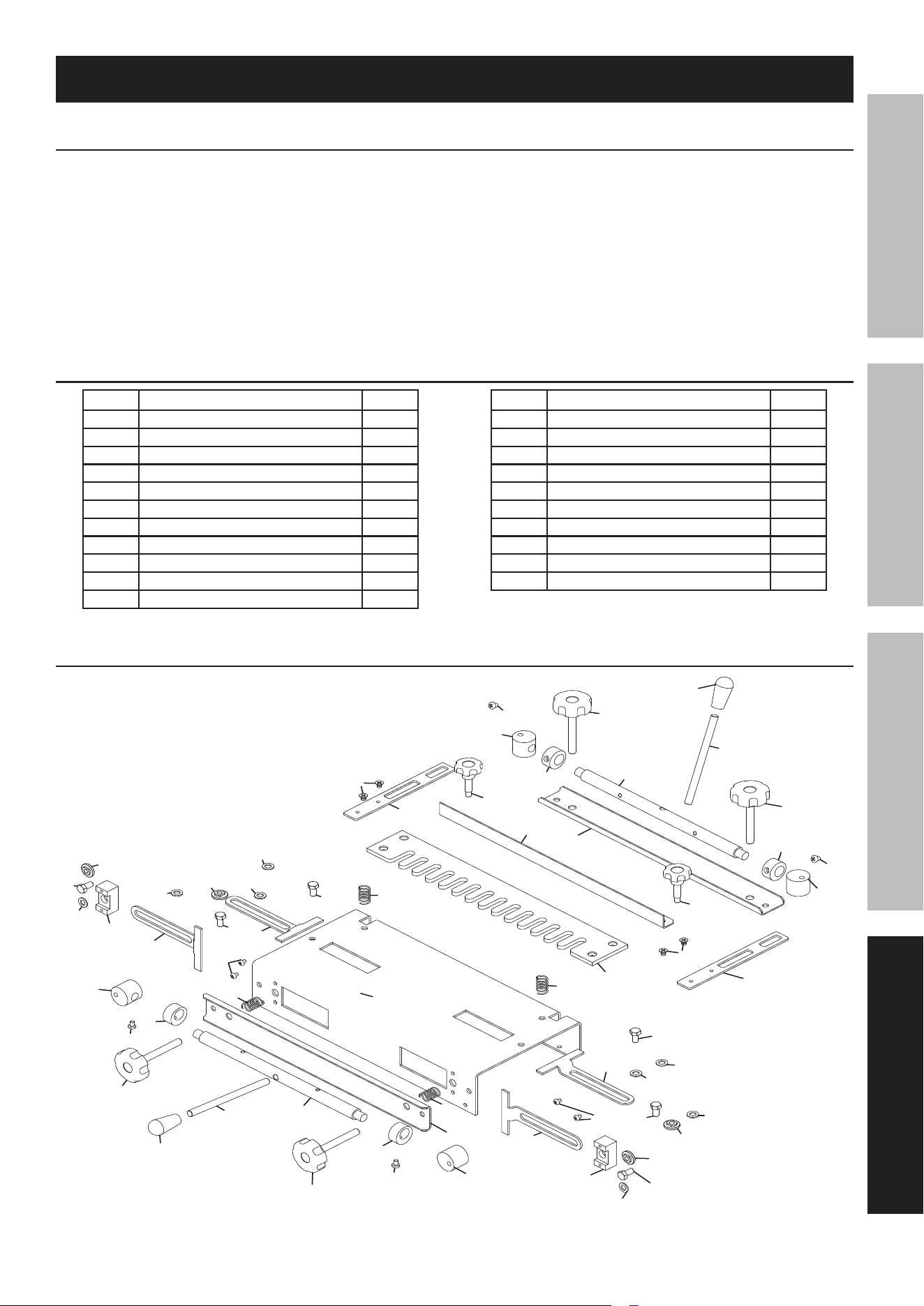
note: Some parts are listed and shown for illustration purposes only, and are not
available individually as replacement parts. Reference UPC 193175485205.
Page 11For technical questions, please call 1-888-866-5797.Item 59785
SaFetyOperatiOnMaintenance Setup
parts List and Diagram
pLeaSe reaD tHe FOLLOWinG careFuLLy
THE MANUFACTURER AND/OR DISTRIBUTOR HAS PROVIDED THE PARTS LIST AND ASSEMBLY DIAGRAM
IN THIS MANUAL AS A REFERENCE TOOL ONLY. NEITHER THE MANUFACTURER OR DISTRIBUTOR
MAKES ANY REPRESENTATION OR WARRANTY OF ANY KIND TO THE BUYER THAT HE OR SHE IS
QUALIFIED TO MAKE ANY REPAIRS TO THE PRODUCT, OR THAT HE OR SHE IS QUALIFIED TO REPLACE
ANY PARTS OF THE PRODUCT. IN FACT, THE MANUFACTURER AND/OR DISTRIBUTOR EXPRESSLY
STATES THAT ALL REPAIRS AND PARTS REPLACEMENTS SHOULD BE UNDERTAKEN BY CERTIFIED AND
LICENSED TECHNICIANS, AND NOT BY THE BUYER. THE BUYER ASSUMES ALL RISK AND LIABILITY
ARISING OUT OF HIS OR HER REPAIRS TO THE ORIGINAL PRODUCT OR REPLACEMENT PARTS
THERETO, OR ARISING OUT OF HIS OR HER INSTALLATION OF REPLACEMENT PARTS THERETO.
parts List
part Description Qty
1 Base 1
2 Washer M8 8
3 Bolt M8x16 6
4 Nut M8 4
5 Side Brace 2
6 Fence Knob 2
7 Clamp Knob 4
8 Eccentric Bushing 4
9 Eccentric Cam 4
10 Rod 2
11 Lever Knob 2
part Description Qty
12 Lever Rod 2
13 Set Screw M5x12 4
14 Spring 4
15 Fence 1
16 Screw M6x10 4
17 1/2" Template 1
18 Stop 4
19 Screw M5x16 4
20 Support 2
21 Clamp 2
assembly Diagram
1
2
3
4
5
6
7
8
9
10
11
12
13
14
15
16
17
18
19
20
21
7
11
12
7
7
10
13
13
13
8
9
8
9
8
9
18
18
18
21
14
14
14
3
3
3
3
3
6
5
16
2
2
2
2
2
2
2
20
19
4
4
4

Limited 90 Day Warranty
Harbor Freight Tools Co. makes every effort to assure that its products meet high quality and durability standards,
and warrants to the original purchaser that this product is free from defects in materials and workmanship for the
period of 90 days from the date of purchase. This warranty does not apply to damage due directly or indirectly,
to misuse, abuse, negligence or accidents, repairs or alterations outside our facilities, criminal activity, improper
installation, normal wear and tear, or to lack of maintenance. We shall in no event be liable for death, injuries
to persons or property, or for incidental, contingent, special or consequential damages arising from the use of
our product. Some states do not allow the exclusion or limitation of incidental or consequential damages, so the
above limitation of exclusion may not apply to you. THIS WARRANTY IS EXPRESSLY IN LIEU OF ALL OTHER
WARRANTIES, EXPRESS OR IMPLIED, INCLUDING THE WARRANTIES OF MERCHANTABILITY AND FITNESS.
To take advantage of this warranty, the product or part must be returned to us with transportation charges
prepaid. Proof of purchase date and an explanation of the complaint must accompany the merchandise.
If our inspection verifies the defect, we will either repair or replace the product at our election or we may
elect to refund the purchase price if we cannot readily and quickly provide you with a replacement. We will
return repaired products at our expense, but if we determine there is no defect, or that the defect resulted
from causes not within the scope of our warranty, then you must bear the cost of returning the product.
This warranty gives you specific legal rights and you may also have other rights which vary from state to state.
26677 agoura road • calabasas, ca 91302 • 1-888-866-5797