Installation Instructions, and
Use and Care Guide
RESIDENTIAL
CONDENSING GAS
WATER HEATERS
Power Vent / Power Direct Vent Gas Models
with Hot Surface Ignion
Series 120-121
Not For Use in Manufactured (Mobile) Homes
Improper installa�on, opera�on,
altera�on, or service might cause a
malfunc�on that results in property
damage, personal injury, or death.
Read and understand this instruc�on
manual and the safety messages
before installing, opera�ng, or
servicing this water heater.
This manual must remain with the
water heater.
Safety Hazard
WARNING
⚠
WARNING: If the informaon in
these instrucons is not followed
exactly, a re or explosion may
result causing property damage,
personal injury, or death.
— Do not store or use gasoline or other
ammable vapors and liquids in the
vicinity of this or any other appliance.
— WHAT TO DO IF YOU SMELL GAS:
• Do not try to light any appliance.
• Do not touch any electrical switch;
do not use any phone in your
building.
• Immediately call your gas supplier
from a neighbor’s phone. Follow the
gas supplier’s instrucons.
• If you cannot reach your gas
supplier, call the re department.
— Installaon and service must be
performed by a qualied installer,
service agency, or the gas supplier.
LOW LEAD
CONTENT
Place these instrucons adjacent to heater and nofy owner to keep for future reference.
Keep this manual in the pocket on heater for future reference whenever maintenance adjustment or service is required.
PRINTED 1123 100368549_2000624920B

CONTENTS
COMPLETED INSTALLATION (TYPICAL).........3
IMPORTANT SAFETY INFORMATION ............4
Do Not Operate If Damaged ...................4
Hydrogen Gas Flammable .......................4
Liming the Risk of Scalding ...................4
Warning Messages ...............................5
Risks During Installaon and
Maintenance ...........................................6
Risks During Operaon ...........................6
Water Contamination Risk ............... 7
Fire Risk
........................................... 7
Explosion Risk .........................................7
Carbon Monoxide Risk ............................8
INTRODUCTION ...........................................10
Abbreviaons Used...............................10
Qualicaons ........................................ 10
Qualified Installer or Service
Agency
.......................................... .10
Important Denions ...........................10
Preparing For Installaon .....................11
MASSACHUSETTS INSTALLATION
REQUIREMENTS ...........................................12
FEATURES AND COMPONENTS ...................13
Model Characteristics ......................... 15
Controls and Switches
....................... 15
Control Module
............................. 15
Pressure Switches
.......................... 15
Outlet Air Pressure Switch (OAPS)
. 15
Intake Air Pressure Switch (IAPS)
... 15
Hot Surface Igniter (HSI)
................ 15
Flame Sensor
................................. 15
GETTING STARTED .......................................16
Before you Begin ................................16
Recommended Accessories: .................16
Rough-In Dimensions..........................17
Verify that Your Home is Equipped and
Up-To-Date for Proper Operaon .........18
Water Pressure .............................. 18
Water Pressure Increase Caused by
Thermal Expansion
........................ 18
Water Pipe and Tank Leaks
............ 18
Water Temperature Regulaon ............18
Verify that the Locaon is
Appropriate ..........................................19
Removing the Old Water Heater ..........20
Combuson Air and Venlaon ............21
Corrosion and Water Quality ................21
Install Shut-O and Thermostac Mixing
Valves ....................................................21
INSTALLING THE VENT SYSTEM ..................22
Planning the Vent System .....................22
Vent Kit .................................................22
Vent Pipe Material ................................23
Vent Pipe Length and Sizing ..................23
Polypropylene Vent Systems .................23
Vent Pipe Runs .............................. 24
Vent Pipe Installaon ............................ 24
Vent Screens .........................................24
Installing the Exhaust/Condensate Tee .24
Important Notes and Warnings ............25
Power Direct Venng (PDV) ..................25
Direct Vent Air Intake Moisture
Protecon .............................................25
Termination Clearances Sidewall Power
Vent
.......................................... .......... 26
Side Wall Vent Terminaon (Standard) . 27
Roof Vent Termination (Standard) .27
Side Wall Vent For Cold Climates .......... 27
Concentric Vent Terminaon ................27
Mulple Concentric Vent Terminaon ..28
Low Prole Vent Installaon ................. 29
Calculating Equivalent Feet (PDV) .......30
Installing a New Tee Terminaon ..........31
Installing a New 90° Terminaon .......... 31
Power Vent (PV) ....................................31
Termination Clearances Other than
Sidewall Direct Vent
........................... 32
Calculang Equivalent Feet (PV) ...........34
Vent Installaon ....................................34
Condensate (Exhaust) ........................... 34
INSTALLING THE WATER HEATER................35
Water Line Connecons ........................35
Thermostac Point-of-Use Mixing
Valves ....................................................35
Closed Water Systems ..........................36
Thermal Expansion ...............................36
Temperature-Pressure Relief Valve ....... 37
T&P Valve Discharge Pipe ..............37
Space Heang Applicaons ..................38
Combo Heating .............................. 38
System Requirements
.................... 38
Combo Heating Installation
...........39
Electrical Installation
.......................... 39
Grounding Instructions
..................39
Electrical Supply
............................ 39
Dedicated Power Wiring and
Breakers
........................................ 39
Power Fluctuations and Electrical
Noise
.............................................39
Electrical Wiring
............................ 40
Making the Electrical Connections
40
Gas Supply System Installation
...........40
Gas Supply Regulator
.....................40
Gas Line Installation
......................41
Gas Line Sizing
............................... 42
Gas Supply Line Leak Testing
.........43
Gas Supply Line Purging.................43
Water Heater Gas Leak Testing
...... 43
High Altude Installaons ....................43
Connecng the Water Supply ...............43
Installation Checklist ..........................44
Water Heater Location
..................44
Gas Supply And Piping
................... 44
Vent Pipe System
........................... 44
Vent Termination
........................... 44
Vertical
........................................44
Water System Piping
......................44
Electrical Connections
...................44
START UP AND OPERATIONS .......................45
Start Up Condions ..............................45
Smoke/Odor .........................................45
Prior to Start up ....................................45
Filling the Water Heater........................45
Inial Start Up .......................................45
Required Test Equipment ...............45
Preparation....................................45
Lighting The Water Heater
.............46
TEMPERATURE REGULATION ......................47
Temperature Control ............................47
Hot Water Can Scald ............................. 47
High Temperature Applicaons ............48
High Temperature Limit Control (ECO) .48
CONTROL SYSTEM OPERATION ..................49
Icons .....................................................49
Buons .................................................49
ON/OFF ................................................. 49
Lock/Unlock .......................................... 49
Temperature Setpoint ...........................49
Normal Mode / Vacaon Mode ............ 49
Burner In Operaon ..............................49
Switching Between Temperature Units 49
Fault Indicaon .....................................49
Service Mode ........................................49
MAINTENANCE ............................................50
Venng System Inspecon ....................50
Draining and Flushing ...........................50
Draining the Storage Tank .............. 50
Flushing the Storage Tank
..............50
Sediment Removal ................................ 51
Lime Scale Removal .......................51
Chemical Lime Scale Removal
........51
Burner Operaon And
Inspecon .............................................51
Combuson Chamber And Burner
Cleaning ................................................ 51
Housekeeping .......................................52
Maintain Minimum Clearances.............52
Anode Rod Maintenance ......................52
Temperature-Pressure Relief Valve Test 52
Service ..................................................53
TROUBLESHOOTING ....................................54
Service Mode ........................................54
Outlet Air Pressure Switch (OAPS) ........ 54
Intake Air Pressure Switch (IAPS) .......... 54
Basic Sequence Of Operaon ...............55
Call for Heat: ................................. 55
Monitor Flame Current
..................55
Burner Ignition Sequence
.............. 55
Water Leak Detecon ...........................55
Clearing Error Codes .............................56
Error Priority..................................57
Checking for leaks ................................. 57
DIAGRAMS ....................................................58
Wiring Diagram ..................................58
SERVICE PARTS LIST .....................................59
2 • Residenal Condensing Gas Water Heaters
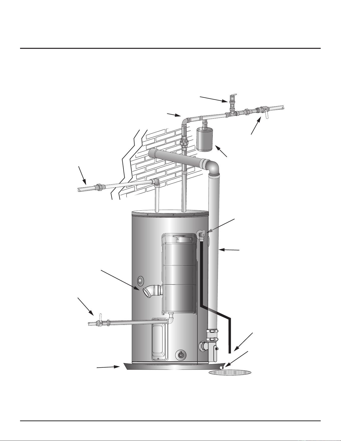
COMPLETED INSTALLATION (TYPICAL)
Hot Water Line
Expansion Tank
Water Shut Off Valve
Cold Water Line
T&P Relief Valve
T&P
Discharge
Pipe
Drain Pan
Discharge
Pipe
Gas
Shut-Off
Valve
Drain Pan
Exhaust
Vent Pipe
Intake Air Connec�on
Vacuum Relief Valve
Figure 1. Typical Installation
Residenal Condensing Gas Water Heaters • 3
IMPORTANT SAFETY INFORMATION
To reduce the risk of property damage, serious
injury or death, read and follow the precauons
below, all labels on the water heater, and the
safety messages and instrucons throughout
this manual.
DO NOT OPERATE IF DAMAGED
DO NOT USE THIS WATER HEATER IF ANY PART
HAS BEEN EXPOSED TO FLOODING OR WATER
DAMAGE. Immediately call a qualied service
agency to inspect the water heater and to
make a determinaon on what steps should
be taken next.
If the unit is exposed to the following, do not
operate heater unl all correcve steps have
been made by a qualied service agency.
1. External re.
2. Damage.
3. Firing without water.
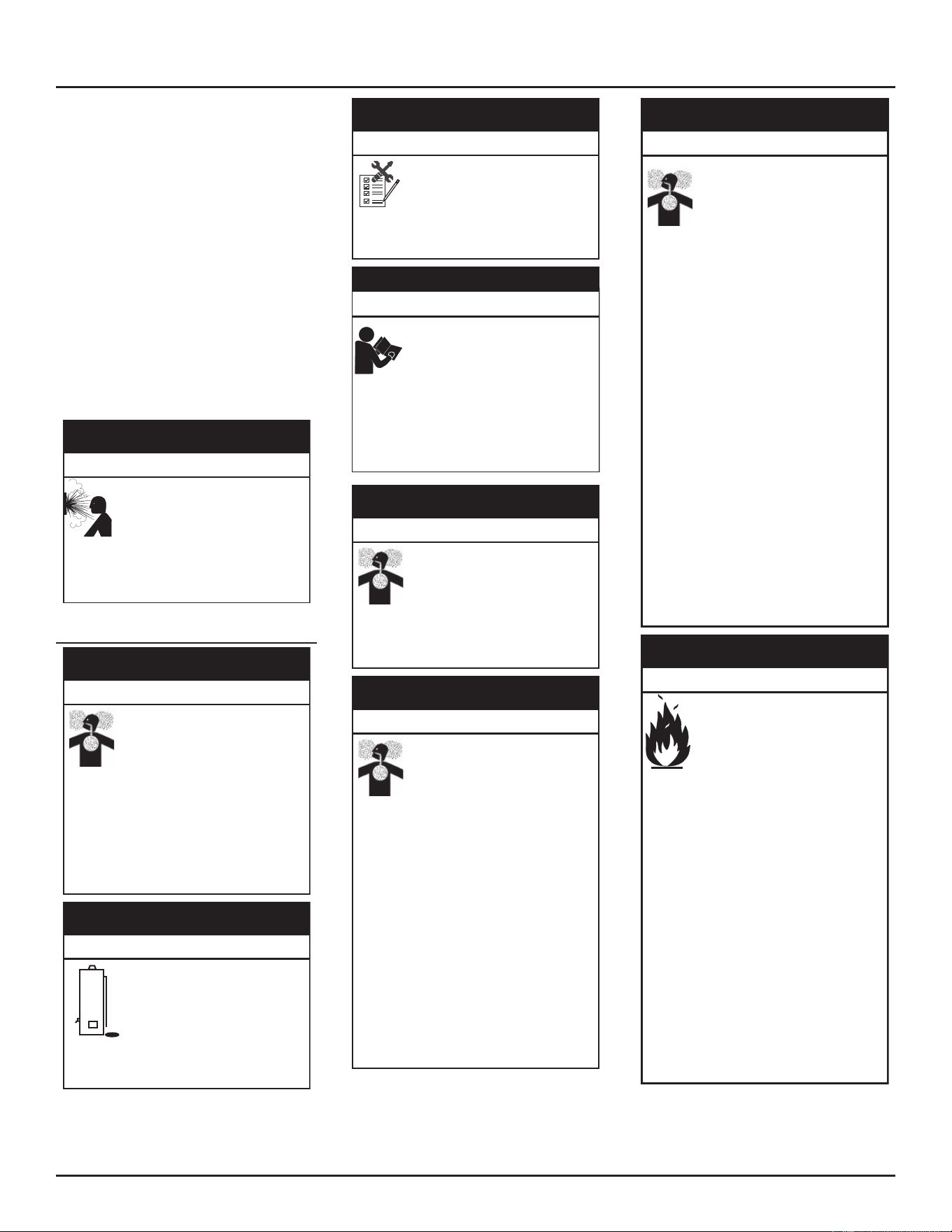
HYDROGEN GAS FLAMMABLE
Hydrogen gas can be produced in a hot water
system served by this water heater that has not
been used for a long period of me (generally
two weeks or more). Hydrogen gas is extremely
ammable. To reduce the risk of injury under
these condions, it is recommended that a
hot water faucet served by this water heater
be opened for several minutes before using
any electrical appliance connected to the hot
water system. If hydrogen is present there
will probably be an unusual sound such as air
escaping through the pipe as the water begins
to ow. THERE SHOULD BE NO SMOKING OR
OPEN FLAME NEAR THE FAUCET AT THE TIME
IT IS OPEN.
Hydrogen gas can accumulate in
water pipes that have been unused
for several days. If there is an
igni�on source near the faucet when
you turn it on, it could ignite the hydrogen and
cause an explosion.
Keep all ignition sources away from the
faucet when turning on hot water.
Explosion Hazard
WARNING
⚠
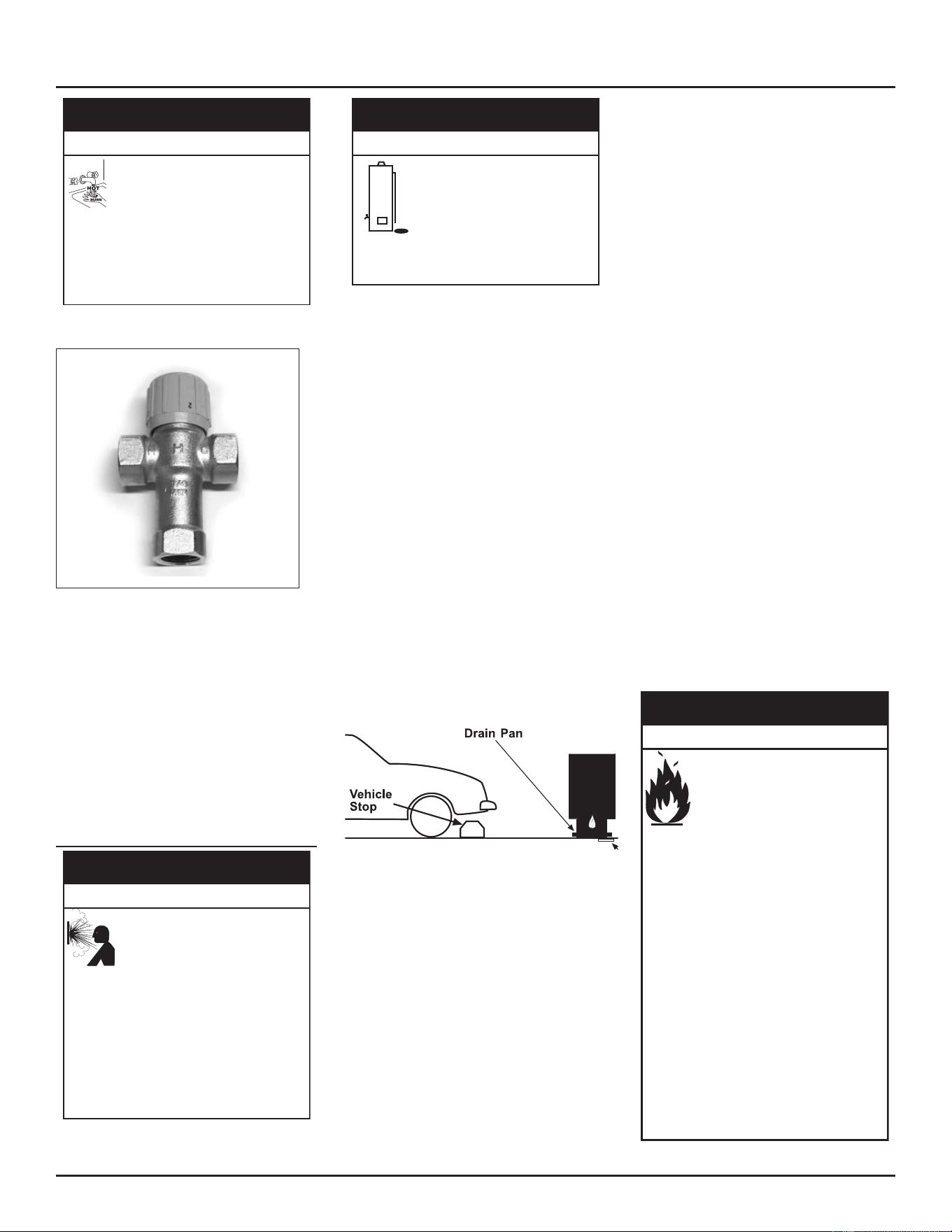
LIMITING THE RISK OF SCALDING
For a variety of reasons, water heaters can
produce water that is much hoer than its
temperature setting. Take precautions to
prevent this higher temperature water from
reaching the water xtures.
Higher temperatures over 120°F
(49°C) can cause severe burns
instantly resul�ng in severe injury
or death.
To reduce the risk of unusually hot water
reaching the fixtures in the house, install
thermostatic mixing valves at each point of
use.
Burn Hazard
DANGER
⚠
According to a naonal standard (ASSE 1070)
and many local plumbing codes, the water
heater’s gas control valve should not be used as
the sole means to regulate water temperature
and avoid scalds.
A properly adjusted thermostac mixing valve
at each point of use allows you to set the
tank temperature to a higher seng without
increasing risk of scalds. A higher temperature
setting allows the tank to provide much
more hot water and can help provide proper
water temperatures for appliances such as
dishwashers and washing machines.
Higher tank temperatures (140°F) also kill
bacteria that cause a condition known as
“smelly water” and can reduce the levels of
bacteria that cause water-borne diseases.
4 • Residential Condensing Gas Water Heaters
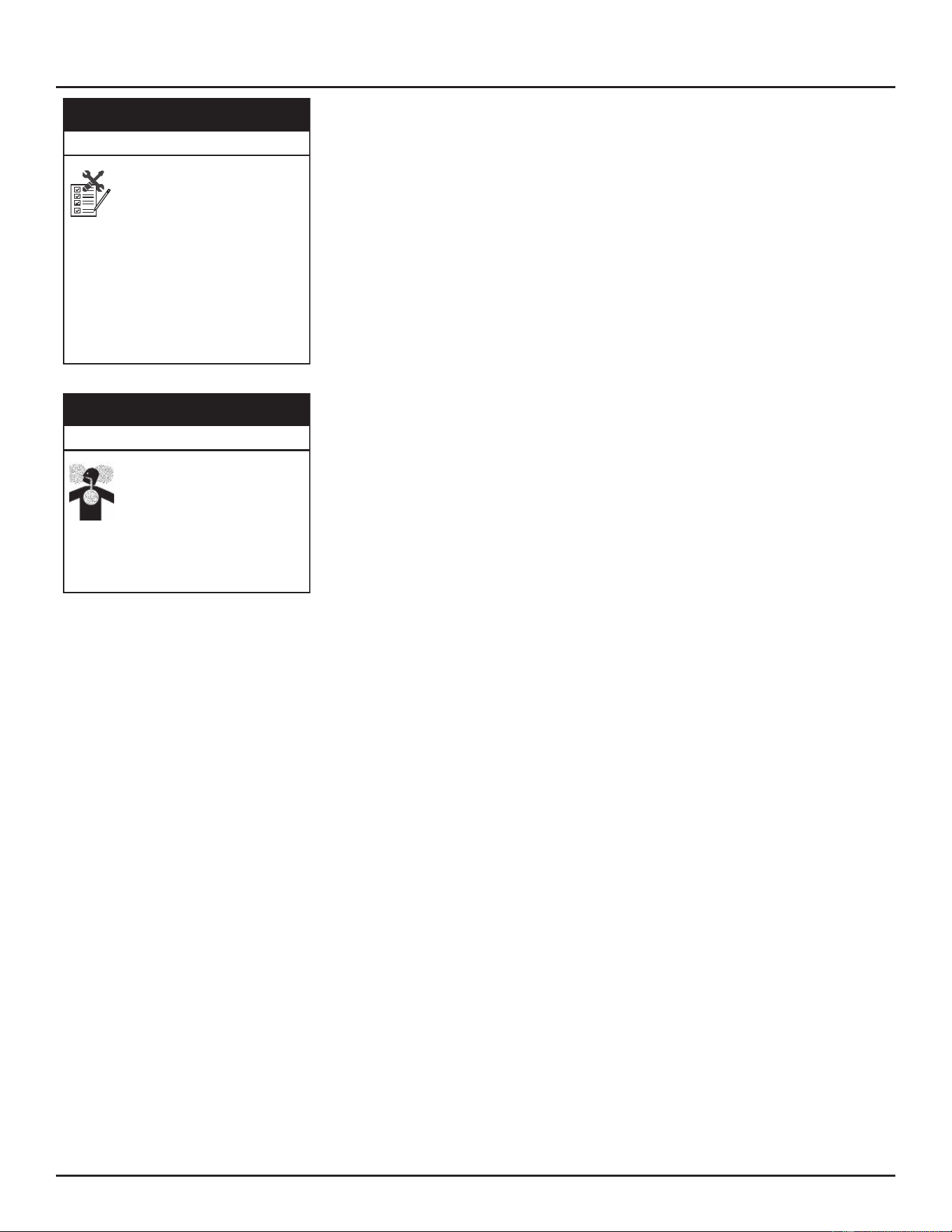
WARNING MESSAGES
Read and follow all safety messages and instrucons in this manual.
Related messages and instrucons have been provided in this manual
and on your own water heater to warn you and others of a potenal
injury hazard. Read and obey all safety messages and instrucons
throughout this manual. It is very important that the meaning of each
safety message is understood by you and others who install, use or
service this water heater.
Many safety-related messages and instrucons have been provided in
this manual and on your own water heater to warn you and others of a
potenal injury hazard. Read and obey all safety messages and instrucons
throughout this manual. It is very important that the meaning of each
safety message is understood by you and others who install, use, or service
this water heater.
This is the safety alert symbol. It is used
to alert you to potenal personal injury
hazards. Obey all safety messages that
follow this symbol to avoid possible
injury or death. Keep this manual near
the water heater.
DANGER DANGER
DANGER indicated an imminently
hazardous situaon which, if not
avoided, will result in injury or death.
WARNING WARNING
WARNING indicates a potenally
hazardous situaon which if not avoided
could result in injury or death.
CAUTION CAUTION
CAUTION indicates a potenally
hazardous situaon which, if not
avoided, could result in minor or
moderate injury.
CAUTION CAUTION
CAUTION used without the safety alert
symbol indicates a potenally hazardous
situaon which, if not avoided could
result in property damage
All safety messages will generally tell you about the type of hazard, what
can happen if you do not follow the safety message, and how to avoid
the risk of injury.
Important informaon to keep
Fill out this secon and keep this manual in the pocket of the
water heater for reference.
Date Installed:
Model Number:
Serial Number:
Maintenance
Performed:* Date
*Drain and ush tank and remove and inspect anode rod aer
rst six months of operaon and at least annually thereaer.
Operate the Temperature and Pressure Relief Valve (T&P)
annually and inspect T&P valve every 2-4 years (see the label
on the T&P valve for maintenance schedule). If no label is
aached to the T&P Relief Valve, follow the instrucons in
the T&P Relief Valve Maintenance secon of this manual.
See the Maintenance secon for more informaon about
maintaining this water heater.
IMPORTANT SAFETY INFORMATION
Residenal Condensing Gas Water Heaters • 5
To reduce the risk of property damage, serious
injury or death, read and follow the precauons
below, all labels on the water heater, and the
safety messages and instrucons throughout
this manual.
RISKS DURING INSTALLATION AND MAINTE-
NANCE
WARNING
Read this manual and the labels on the water
heater before you install, operate, or service it.
If you have difficulty following the directions, or
aren’t sure you can safely and properly do any
of this work yourself:
• Call our Technical Assistance Hotline at
1-877-817-6750 or visit http://ww-
w.AOSmithAtLowes.com. We can help you
with installation, operations, troubleshooting,
or maintenance. Before you call, write down
the model and serial number from the water
heater’s data plate.
• Incorrect installation, operation, or service
can damage the water heater, your house
and other property, and present risks,
including fire, scalding, electric shock, and
explosion, causing serious injury or death.
DO NOT RETURN THIS UNIT TO THE STORE.
Contact with wiring or electrical
connec�ons can result in electrical
shock, resul�ng in sever injury, or
death.
Do the following to avoid this hazard:
• Disconnect power by opening the circuit
breaker or removing the fuses before
installing or servicing.
• Use a non-contact circuit tester to confirm
that power is off before working on or near
any electrical parts.
• Replace the junction box cover and access
doors after servicing.
Electrical Shock Hazard
WARNING
⚠
This water heater is too heavy to
be carried safely by one person.
A�emp�ng to do so could cause
serious injury.
Avoid this hazard by doing the following:
• Use at least two people to lift the water
heater.
• Be sure you both have a good grip before
lifting.
•
Use an appliance dolly or hand truck to move
the water heater.
Li Hazard
WARNING
⚠
The water heater is designed for a
specific type of gas, a specific gas
pressure, and a specific firing rate.
Changing any of these parameters
might cause the water heater to
explode and catch fire, resul�ng in
property damage, personal injury, or death.
Do the following to avoid these hazards:
• Do not connect a natural gas water heater to
an L.P. gas supply.
• Do not connect an L.P. gas water heater to a
natural gas supply.
• Use a pressure reducer valve to match gas
supply line pressure to the water heater’s
rated pressure.
• Use a new CSA approved gas supply line.
• Under no circumstances should the input
exceed the rate shown on the water heater’s
rating label.
• Install a shut-off valve on the gas supply line.
• Read the instruction manual before
installing, using, or servicing the water
heater.
• Contact a qualified installer or service agency
for installation and service.
Fire and Explosion Hazard
WARNING
⚠
RISKS DURING OPERATION
Water temperature over 125°F
(52°C) can cause severe burns
instantly resul�ng in severe injury
or death.
Observe the following precau�ons to avoid
this hazard:
• Children, the elderly, and the physically or
mentally disabled are at highest risk for scald
injury.
• Feel water before bathing or showering.
• Temperature limiting devices, such as
thermostatic point-of-use mixing valves must
be installed when required by codes and to
ensure safe temperatures at fixtures.
• The thermostat(s) on this water heater
has been factory set to approximately
120°F to reduce the risk of scalding. Higher
temperatures increase the risk of scalding,
but even at 120°F, hot water can scald. If you
choose a higher temperature, thermostatic
mixing valves, located at each point-of-use
are particularly important to help avoid
scalding.
• Thermostatic mixing valves located at each
point of use are particularly important to
avoid scalding.
Burn Hazard
⚠
DANGER
Table 1. Burn Time at Various
Temperatures
Water
Tempera-
ture
°C (°F)
Time for 1st Degree
Burn
(Less Severe
Burns)
Time for
Permanent
Burns 2nd &
3rd Degree
(Most Se-
vere Burns)
43 (110) (shower temp.)
47 (116) (pain threshold)
47 (116) 35 minutes 45 minutes
50 (122) 1 minute 5 minutes
55 (131) 5 seconds 25 seconds
60 (140) 2 seconds 5 seconds
65 (149) 1 second 2 seconds
68 (154) instantaneous 1 second
(U.S. Government Memorandum, C.P.S.C., Peter L.
Armstrong, Sept. 15, 1978)
For more information about changing the
factory temperature seng, see Temperature
Regulation (page 47).
Even if you set the water heater’s
temperature control to a low seng, higher
water temperatures may occur in certain
circumstances.
• In some cases, repeated small draws
of water can cause the hot and cold
water in the tank to “stack” in layers.
If this happens, the water can be as
much as thirty degrees hoer than
the temperature control seng. This
temperature variaon is the result of your
usage paern and is not a malfuncon.
• Water temperature will be hoer if
someone adjusted the temperature
control to a higher seng.
• Problems with the gas control valve or
other malfuncons may result in higher
than expected water temperatures.
• If the water heater is in a hot
environment, the water in the tank can
become as hot as the surrounding air,
regardless of the temperature seng.
• If the water supplied to the water
heater is pre-heated (by a solar heang
system) the temperature in the tank
may be higher than the water heater’s
temperature seng.
• Should overheang occur or the burner
fail to shut o, turn o the manual gas
supply valve to the water heater and call a
qualied person.
IMPORTANT SAFETY INFORMATION
6 • Residenal Condensing Gas Water Heaters
Higher temperatures over 120°F
(49°C) can cause severe burns
instantly resul�ng in severe injury or
death.
To reduce the risk of unusually hot water
reaching the fixtures in the house, install
thermosta�c mixing valves at each point of
use.
Burn Hazard
⚠
WARNING
If anyone in your home is at parcular risk of
scalding (for example, the elderly, children, or
people with disabilies) or if there is a local
code or state law requiring a certain water
temperature at the hot water tap, these
precauons are parcularly important.
According to a national standard American
Society of Sanitary Engineering (ASSE 1070)
and most local plumbing codes, the water
heater’s thermostat should not be used as the
sole means to regulate water temperature and
avoid scalds.
Properly adjusted thermostac mixing valves
installed at each point-of-use allow you to
set the tank temperature to a higher seng
without increasing the risk of scalds. A higher
temperature seng allows the tank to provide
much more hot water and can help provide
proper water temperatures for appliances such
as dishwashers and washing machines. Higher
tank temperatures (140°F) also kill bacteria that
cause a condion known as “smelly water” and
can reduce the levels of bacteria that cause
water-borne diseases.
This water heater’s ven�ng system
can become hot enough to burn.
Do not touch the ven�ng system
while water heater is on, or un�l
the water heater is turned off and ven�ng
allowed to cool.
Burn Hazard
⚠
WARNING
Water Contamination Risk
Connec�ng the water heater to a
non-potable water system might
result in chemical or biological
contamina�on of the water heater.
Do not connect the water heater to a
non-potable water system.
Toxic Chemical Hazard
⚠
WARNING
Fire Risk
To reduce the risk of a re that could destroy
your home and seriously injure or kill people,
read and observe the following warning
messages:
Contaminants in gas lines can cause
fire or explosion.
Do the following to avoid this
hazard:
• Clean all gas piping before
installation.
• Install sediment trap in accordance
with
NFPA54
or
CSA-B1491
.
• Be sure the junction box cover and the
access door covers are in place.
• These covers keep debris from
entering and potentially being ignited,
and help keep any internal fires from
spreading.
Fire and Explosion Hazard
⚠
WARNING
Improper installa�on of electrical
connec�ons can cause the water
heater to catch fire.
Do the following to avoid this hazard:
• Make electrical connections properly,
according to the instructions.
• Use 10 gauge solid copper wire.
• Use a UL listed or CSA approved strain
relief.
• Connect ground wire to green ground
screw.
Property Damage Hazard
⚠
CAUTION
Under certain condi�ons, the water
heater can explode and catch fire,
resul�ng in property damage,
personal injury, or death.
Do the following to avoid these
condi�ons:
• Do not store or use gasoline or other
flammable vapors and liquids in the vicinity
of this or any other appliance.
• Avoid all ignition sources if you smell gas.
• Do not expose water heater controls to
excessive gas pressure.
•
Use only the gas shown on the water heater
rating label.
• Maintain required clearances to
combustibles.
• Keep ignition sources away from faucets
after extended periods of non-use.
Fire and Explosion Hazard
⚠
WARNING
Exposure to water or flood
condi�ons can cause the water
heater to catch fire or explode.
• Keep the water heater from
becoming wet. Immediately shut
the water heater off and have it
inspected by a qualified person
if you find that the wiring, thermostat(s) or
surrounding insulation have been exposed
to water in any way (e.g., leaks from
plumbing, leaks from the water heater itself
can damage property and could cause a fire
risk).
• If the water heater is subjected to flood
conditions or the thermostat(s) have been
submerged in water, the entire water
heater must be replaced.
• Make electrical connections properly,
according to these instructions. Use 10
gauge solid copper wire. Use a UL listed or
CSA approved strain relief.
Fire and Explosion Hazard
⚠
WARNING
EXPLOSION RISK
High temperature or pressure in
the water heater can cause the
water heater to explode resul�ng
in severe injury or death.
• A properly sized temperature-pressure
relief valve must be installed in the opening
provided.
• The temperature-pressure relief valve must
comply with
ANSI Z21.22-CSA4.4
and
ASME
code.
• Do not plug, block, or cap the discharge
line.
Property Damage Hazard
⚠
CAUTION
IMPORTANT SAFETY INFORMATION
Residenal Condensing Gas Water Heaters • 7
A nationally recognized testing laboratory
maintains public inspection of the valve
producon process and ceres that it meets
the requirements for Relief Valves for Hot Water
Supply Systems, ANSI Z21.22. The T&P Relief
Valve’s relief pressure must not exceed the
working pressure rang of the water heater as
stated on the rang plate.
Maintain the T&P Relief Valve properly. Follow
the maintenance instrucons provided by the
manufacturer of the T&P Relief Valve (label
aached to T&P Relief Valve). If no label is
aached to the T&P Relief Valve, follow the
instructions in Temperature-Pressure Relief
Valve Test (page 52). An explosion could
occur if the T&P Relief Valve or discharge pipe
is blocked. Do not cap or plug the T&P Relief
Valve or discharge pipe.
Hydrogen gas can accumulate in
water pipes that have been unused
for several days. If there is an
igni�on source near the faucet when
you turn it on, it could ignite the hydrogen and
cause an explosion.
Keep all ignition sources away from the
faucet when turning on hot water.
Explosion Hazard
WARNING
⚠
CARBON MONOXIDE RISK
An improperly installed water
heater can emit carbon monoxide.
Breathing carbon monoxide can
cause brain damage or death.
Do the following to avoid carbon monoxide
poisoning:
• Install the water heater in accordance with
the instruction manual and NFPA 54.
• To avoid injury, combustion and ventilation
air must be taken from outdoors.
• Do not place chemical vapor emitting
products near water heater.
Breathing Hazard-Carbon Monoxide Gas
⚠
WARNING
Over �me, the tank and fi�ngs of
the water heater can begin to leak
and cause water damage.
Locate the water heater in an
area where water leakage from
the heater or connec�ons will not result in
damage to the area or the lower floors of
the structure.
Property Damage Hazard
⚠
CAUTION
Improper installa�on use and
service could result in property
damage.
This unit must be configured with both an
air intake terminal and an exhaust
terminal.
Property Damage Hazard
⚠
CAUTION
Improper installa�on, opera�on,
altera�on, or service might cause a
malfunc�on that results in property
damage, personal injury, or death.
Read and understand this instruc�on
manual and the safety messages
before installing, opera�ng, or
servicing this water heater.
This manual must remain with the
water heater.
Safety Hazard
WARNING
⚠
Opera�ng this water heater at
al�tudes above 10,100 feet (3,078
m) can cause it to emit carbon
monoxide. Breathing carbon
monoxide can cause brain damage or death.
Consult with A. O. Smith for installa�ons
above 10,100 feet (3,078 m).
Breathing Hazard-Carbon Monoxide Gas
⚠
WARNING
Certain abnormal condi�ons can
cause the water heater to emit
carbon monoxide. Breathing carbon
monoxide can cause brain damage
or death.
Do the following to prevent these
abnormal condi�ons:
• Do not operate water heater if any part has
been exposed to flooding or water damage.
• Do not operate if soot buildup is present.
• Do not obstruct water heater air intake with
insulating jacket.
• Do not place chemical vapor emitting
products near water heater.
• Never operate the heater unless it is vented
to the outdoors and has adequate air supply
to avoid risks of improper operation, fire,
explosion, or asphyxiation.
• Always read and understand the instruction
manual.
• Install gas and carbon monoxide detectors in
the vicinity of the water heater.
Breathing Hazard-Carbon Monoxide Gas
⚠
WARNING
An improperly installed or
malfunc�oning condensate drain
can cause the water heater to emit
carbon monoxide. Breathing carbon
monoxide can cause brain damage
or death.
Do the following to avoid carbon monoxide
poisoning:
• Install vent system in accordance with local
codes.
• Do NOT elevate any portion of the field
supplied drain line beyond the 1/2” adapter
above the adapter This must be true for the
entire length of the drain line including the
exit into an appropriate drain.
• Condensate lines must be free and
clear of debris and must not allow back
flow through the hose. The condensate
lines must be able to flow freely to an
appropriate drain.
• Do not allow condensate lines to become
crimped closed.
• Analyze the entire vent system to make sure
that condensate will not become trapped in
a section of vent pipe and therefore reduce
the open cross sectional area of the vent.
• Do not install any external condensate trap.
The exhaust tee assembly has an internal
condensate trap.
• Install gas and carbon monoxide detectors in
the vicinity of the water heater.
Breathing Hazard-Carbon Monoxide Gas
⚠
WARNING
Under certain circumstances, the
water heater can explode and catch
fire, resul�ng in property damage,
personal injury, or death.
Do the following to avoid these
condi�ons:
• Do not store or use gasoline or other
flammable vapors and liquids in the vicinity
of this or any other appliance.
• Avoid all ignition sources if you smell gas.
• Do not expose water heater controls to
excessive gas pressure.
• Use only the gas shown on the water
heater rating label.
• Maintain required clearances to
combustibles.
• Keep ignition sources away from faucets
after extended periods of non-use.
• Install sediment trap in accordance with
NFPA54
or
CSA-B1491.
• Read the instruction manual before
installing, using, or servicing the water
heater.
• Contact a qualified installer or service
agency for installation and service.
Fire and Explosion Hazard
⚠
WARNING
IMPORTANT SAFETY INFORMATION
8 • Residenal Condensing Gas Water Heaters
Solvent cements and primers
for plastic pipe are flammable
liquids and emit flammable
vapors. Improper use can cause
an explosion and fire that would
result in property damage.
• Use only in well ventilated areas.
• Do not use near any open flame and all
ignition sources, including water heaters.
•
Use only the solvent cement and primer
appropriate for the venting material being
used.
Property Damage Hazard
⚠
CAUTION
Installing the vent screen
improperly or installing the
wrong screen can cause the water
heater to emit carbon monoxide.
Breathing carbon monoxide can
cause brain damage or death.
Install the appropriate screen designed for
this water heater according to the manual
and all applicable codes.
Breathing Hazard-Carbon Monoxide Gas
⚠
WARNING
IMPORTANT SAFETY INFORMATION
Residenal Condensing Gas Water Heaters • 9

INTRODUCTION
Thank You for purchasing this water heater.
Properly installed and maintained, it should
give you years of trouble free service.
ABBREVIATIONS USED
Abbreviaons found in this Instrucon Manual
include:
• ANSI - American Naonal Standards
Instute
• ASME - American Society of Mechanical
Engineers
• AHRI - Air-Condioning, Heang and
Refrigeraon Instute
• NEC - Naonal Electrical Code
• NFPA - Naonal Fire Protecon
Associaon
• UL - Underwriters Laboratory
• CSA - Canadian Standards Associaon
QUALIFICATIONS
Qualified Installer or Service Agency
Installaon and service of this water heater
requires ability equivalent to that of a Qualied
Agency (as dened by ANSI below) in the eld
involved. Installaon skills such as plumbing,
air supply, venng, gas supply and electrical
supply are required in addion to electrical
tesng skills when performing service.
ANSI Z223.1 2006 Sec. 3.3.83: “Qualified
Agency” - “Any individual, rm, corporaon
or company that either in person or through a
representave is engaged in and is responsible
for (a) the installaon, tesng or replacement
of gas piping or (b) the connecon, installaon,
testing, repair or servicing of appliances
and equipment; that is experienced in such
work; that is familiar with all precautions
required; and that has complied with all
the requirements of the authority having
jurisdicon.”
If you are not qualied (as dened by ANSI
above) and licensed or cered as required by
the authority having jurisdicon to perform a
given task do not aempt to perform any of
the procedures described in this manual. If
you do not understand the instrucons given
in this manual do not aempt to perform any
procedures outlined in this manual.
IMPORTANT DEFINITIONS
Qualified Installer: A qualified installer
must have ability equivalent to a licensed
tradesman in the elds of plumbing, air supply,
venng and gas supply, including a thorough
understanding of the requirements of the
National Fuel Gas Code, ANSI Z223.1/NFPA
54 as it relates to the installaon of gas red
water heaters. The qualied installer must also
be familiar with the design features and use
of ammable vapor ignion resistant water
heaters and have a thorough understanding of
this Installaon and Operang manual.
Service Agency: A service agency also
must have ability equivalent to a licensed
tradesman in the elds of plumbing, air supply,
venng and gas supply, including a thorough
understanding of the requirements of the
National Fuel Gas Code”, ANSI Z223.1/NFPA 54
as it relates to the installaon of gas red water
heaters. The service agency must also have a
thorough understanding of this Installaon
and Operang manual, and be able to perform
repairs strictly in accordance with the service
guidelines provided by the manufacturer.
Gas Supplier: The Natural Gas or Propane
Ulity or service who supplies gas for ulizaon
by the gas burning appliances within this
application. The gas supplier typically has
responsibility for the inspection and code
approval of gas piping up to and including the
Natural Gas meter or Propane storage tank
of a building. Many gas suppliers also oer
service and inspecon of appliances within
the building.
10 • Residential Condensing Gas Water Heaters

PREPARING FOR INSTALLATION
1. Read the enre manual before
aempng to install or operate the water
heater. Pay close aenon to the General
Safety secon of this manual. If you don’t
follow the safety rules, the water heater
may not operate safely. It could cause
property damage, injury and/or death.
2. This manual contains instrucons for the
installaon, operaon, and maintenance
of the water heater. It also contains
warnings throughout the manual that you
must read and be aware of. All warnings
and all instrucons are essenal to the
proper operaon of the water heater
and your safety. Detailed installaon
diagrams are also found in this manual.
These diagrams will serve to provide the
installer with a reference. It is essenal
that all venng, water piping, gas piping
and wiring be installed as shown.
3. Parcular aenon should be given to
the installaon of thermometers as these
are necessary for checking the operaon
of the water heater.
4. The principal components of the water
heater are idened in Features and
Components (page 13). Use this
reference to locate and idenfy various
components on the water heater.
5. See maintenance schedule in Maintenance
(page 50) and Troubleshooting (page
54). By using the troubleshoong
checklist the user may be able to make
minor operaonal adjustments and avoid
unnecessary service calls. However,
service and diagnosc procedures should
only be performed by a Qualied Service
Agency.
Note: Costs to correct installaon errors
are not covered under the limited
warranty.
6. Be sure to turn o power when working
on or near the electrical system of the
water heater. Never touch electrical
components with wet hands or when
standing in water.
7. The installaon must conform with these
instrucons and local code authority
having jurisdicon. In absence of local
codes, installaon must comply with
current edions of the National Fuel
Gas Code, ANSI Z223.1/NFPA 54 and the
National Electrical Code”, NFPA 70. All
documents are available from:
CSA Internaonal
8501 East Pleasant Valley Road
Cleveland, Ohio, United States
44131-5575
NFPA documents are also available from:
Naonal Fire Protecon Associaon
1 Baerymarch Park
Quincy, MA 02269.
8. The water heater, when installed, must be
electrically grounded in accordance with
the local codes or in the absence of local
codes: current edion of the National
Electrical Code, NFPA 70.
9. If aer reading this manual you have
any quesons or do not understand
any poron of the instrucons, call the
toll free number on the front page of
this manual for technical assistance. In
order to expedite your request, please
have the full Model, Serial and Series
number of the water heater you are
working with available for the technician.
This informaon is located on the water
heater’s rang plate.
10. Carefully plan the placement of the water
heater. Examine the locaon to ensure
that it complies with the requirements in
Before you Begin (page 16).
INTRODUCTION
Residenal Condensing Gas Water Heaters • 11

MASSACHUSETTS INSTALLATION REQUIREMENTS
For all side wall terminated, horizontally vented
power vent, direct vent, and power direct vent
gas fueled water heaters installed in every
dwelling, building or structure used in whole or
in part for residenal purposes, including those
owned or operated by the Commonwealth and
where the side wall exhaust vent terminaon
is less than seven (7) feet above nished grade
in the area of the venng, including but not
limited to decks and porches, the following
requirements should be sased:
INSTALLATION OF CARBON MONOXIDE
DETECTORS At the time of installation of
the side wall horizontal vented gas
fueled equipment, the installing plumber or
gasfitter should observe that a hard wired
carbon monoxide detector with an alarm
and baery back-up is installed on the oor
level where the gas equipment is to be
installed. In addion, the installing plumber
or gasfitter should observe that a battery
operated or hard wired carbon monoxide
detector with an alarm is installed on each
addional level of the dwelling, building or
structure served by the sidewall horizontal
vented gas fueled equipment. It should
be the responsibility of the property owner
to secure the services of qualified licensed
professionals for the installaon of hard wired
carbon monoxide detectors.
In the event that the side wall horizontally
vented gas fueled equipment is installed in a
crawl space or an ac, the hard wired carbon
monoxide detector with alarm and battery
back-up may be installed on the next adjacent
oor level.
In the event that the requirements of this
subdivision can not be met at the time of
compleon of installaon, the owner should
have a period of thirty (30) days to comply with
the above requirements provided that during
said thirty (30) day period, a baery operated
carbon monoxide detector with an alarm should
be installed.
APPROVED CARBON MONOXIDE DETECTORS
Each carbon monoxide detector as required in
accordance with the above provisions should
comply with NFPA 720 and be ANSI/UL 2034
listed and CSA cered.
SIGNAGE A metal or plastic identification
plate should be permanently mounted to
the exterior of the building at a minimum
height of eight (8) feet above grade directly
in line with the exhaust vent terminal for
the horizontally vented gas fueled heating
appliance or equipment. The sign should read,
in print size no less than one-half (1/2) inch in
size, GAS VENT DIRECTLY BELOW. KEEP CLEAR
OF ALL OBSTRUCTIONS.
INSPECTION The state or local gas inspector
of the side wall horizontally vented gas fueled
equipment should not approve the installaon
unless, upon inspecon, the inspector observes
carbon monoxide detectors and signage
installed in accordance with the provisions of
248 CMR 5.08(2)(a) 1 through 4.
EXEMPTIONS: The following equipment is
exempt from 248 CMR 5.08(2)(a)1 through 4:
1. The equipment listed in Chapter 10
entled Equipment Not Required To Be
Vented in the most current edion of
NFPA 54 as adopted by the Board; and
2. Product Approved side wall horizontally
vented gas fueled equipment installed
in a room or structure separate from the
dwelling, building, or structure used in
whole or in part for residenal purposes.
MANUFACTURER REQUIREMENTS - GAS
EQUIPMENT VENTING SYSTEM PROVIDED
When the manufacturer of Product
Approved side wall horizontally vented
gas equipment provides a venting system
design or venting system components with
the equipment, the instructions provided
by the manufacturer for installation of the
equipment and the venting system should
include:
1. Detailed instrucons for the installaon of
the venng system design or the venng
system components; and
2. A complete parts list for the venng
system design or venng system.
MANUFACTURER REQUIREMENTS - GAS
EQUIPMENT VENTING SYSTEM NOT PROVIDED
When the manufacturer of a Product Approved
side wall horizontally vented gas fueled
equipment does not provide the parts for
venng the ue gases, but idenes special
venng systems, the following requirements
should be sased by the manufacturer:
1. The referenced special venng system
instrucons should be included with the
appliance or equipment installaon
instrucons; and
2. The special venng systems should
be Product Approved by the Board,
and the instrucons for that system
should include a parts list and detailed
installaon instrucons.
A copy of all installaon instrucons for all
Product Approved side wall horizontally
vented gas fueled equipment, all venting
instructions, all parts lists for venting
instructions, and/or all venting design
instrucons should remain with the appliance or
equipment at the compleon of the installaon.
12 • Residential Condensing Gas Water Heaters
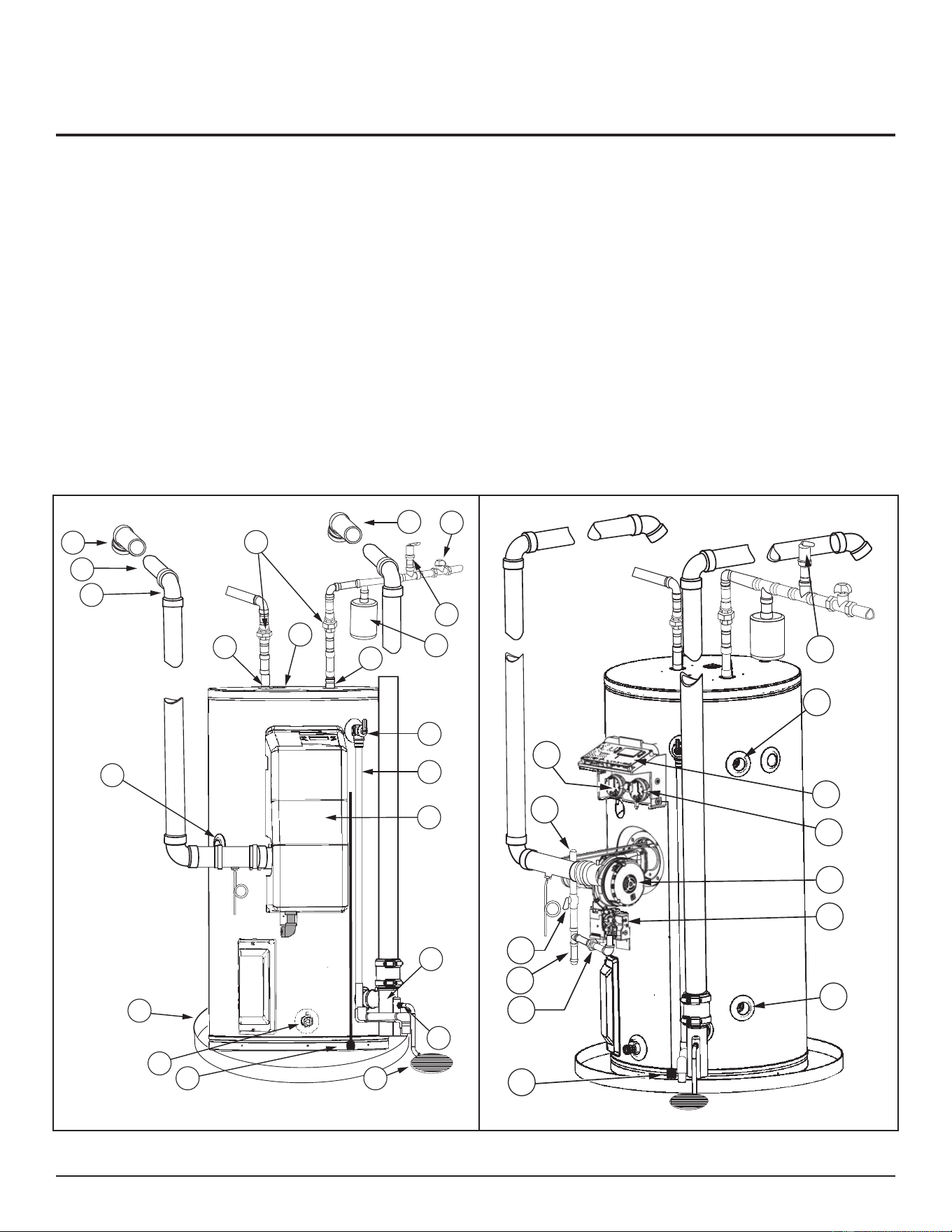
FEATURES AND COMPONENTS
1. Terminaon Elbow With Vent Screen
(included in Vent Kit)
2. *Vent Pipe
3. *Vent Pipe Elbow (Long Radius)
4. *Inlet Water Shut-O Valve
5. *Thermal Expansion Tank
6. *Union (Dielectric Water Connecon)
7. Cold-Water Inlet Nipple/Diptube
8. T&P Valve
9. Discharge Pipe
10. Control Cover (Plasc)
11. Condensate Drain (1/2” MNPT)
12. Condensate Trap/Exhaust Tee
(Included in Vent Kit)
13. Drain Valve
14. *Floor Drain
15. Leak Detecon Module (Oponal)
16. *Metal Drain Pan
17. *Ground Joint Union (Gas Connecon)
18. *Sediment Trap
19. *Main Manual Gas Shut-O Valve
20. *Gas Supply*
21. Intake Air Pressure Switch (IAPS)
22. Hot-Water Outlet Nipple/Anode
23. Anode (Under Cap)
24. **Combo Heang System Supply Outlet
(Oponal)
25. Control Panel
26. Outlet Air Pressure Switch (OAPS)
27. Blower
28. Gas Control Valve
29. **Combo Heang System Return Inlet
(Oponal)
30. Temperature Sensor
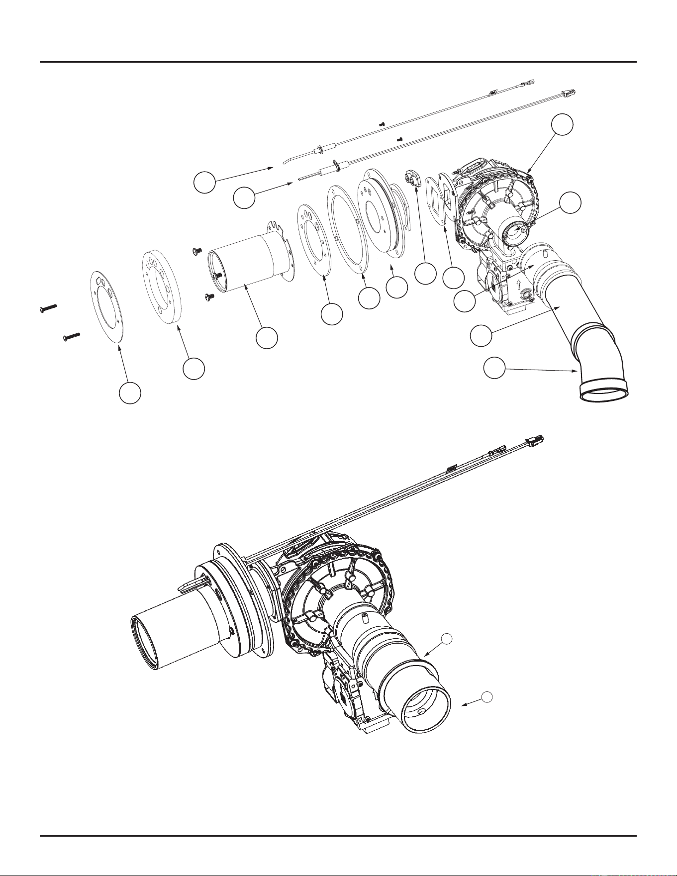
31. Burner Insulaon Shield
32. Burner Refractory
33. Burner
34. Burner Gasket
35. Flange Gasket
36. Ignion Gasket
37. Flame Sensor
38. Hot Surface Igniter
39. Air Intake Venturi
40. Blower Gasket
41. Blower/Burner Flange
42. Air Intake Adapter (Rubber)
43. Air Intake Terminal (Included in Vent Kit)
44. 2” Dia x 3.00” Long Air Intake Pipe
(included in Vent Kit)
45. *Vacuum Relief Valve
†
46. Air Intake Check Valve (LP Models Only)
* Items not supplied with the water heater.
** The side recirculaon loop connecons may not be used as the primary water inlet and outlet connecons. See Combo Heating (page 38).
Venng as shown for PDV (Power Direct Vent) applicaons.
†
Install vacuum relief valve per local codes.
2
3
1
4
13
6
16
23
22
30
5
7
8
9
10
11
14
15
1
12
45
Figure 2. Features and Components - Front
24
25
26
27
28
29
15
17
18
19
20
21
45
Figure 3. Features and Components - Right Side
Residential Condensing Gas Water Heaters • 13
34
35
33
31
32
27
37
38
41
42
44
43
36
40
39
Figure 4. Blower and Intake Air Components for Natural Gas
47
46
Figure 5. Blower and Intake Air Components for LP Gas
FEATURES AND COMPONENTS
14 • Residenal Condensing Gas Water Heaters
MODEL CHARACTERISTICS
Table 2. Gas Pressure and Electrical Characteristics
*Manifold Pressure
Minimum
Supply Pressure
Maximum
Supply Pressure Electrical Characteristics
Gas Type In. W.C. (kPA) In. W.C.(kPA) In W.C.(kPA) Volts/Hz Amperes
Natural 0” (0) 3.5(1.10) 14(3.49) 120/60 <5
Propane 0”(0) 8.0 (1.99) 14 (3.49) 120/60 <5
* The manifold pressure is the factory seng and is not adjustable. A negave pressure will be seen with just the blower running without
the Gas Control Valve open.
CONTROLS AND SWITCHES
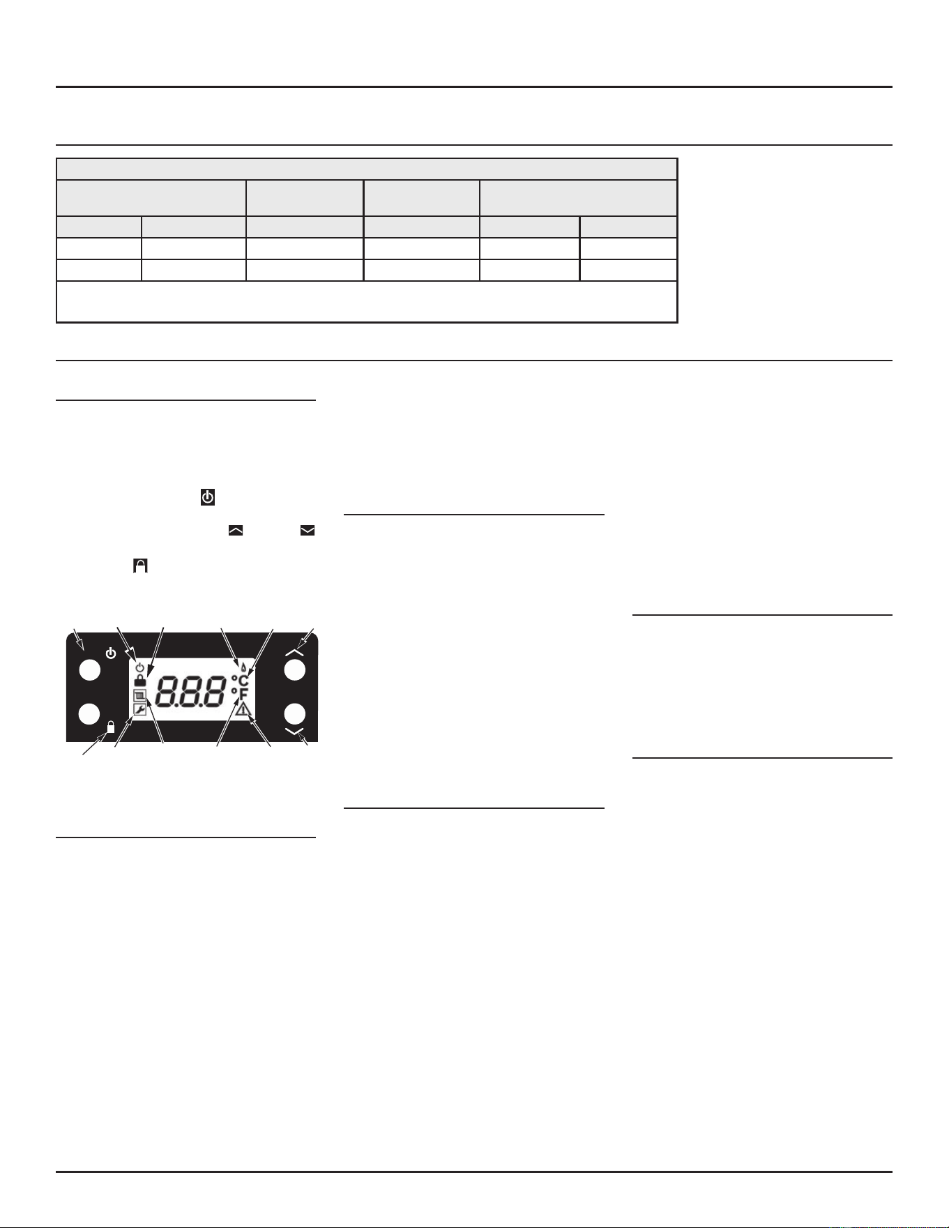
Control Module
This heater includes a control module with a
user interface and a LCD display (see Figure 6).
There are three primary functions of the
control: turn the appliance on/o, set/control
water temperature, seng operang mode. To
turn heater on: hold the (ON/OFF) buon
depressed for 5 seconds. To change desired
setpoint temperature use the (Plus) or
(Minus) buttons, then lock in setpoint by
depressing (Lock/Unlock). For more
informaon on this control module. See Control
System Operation (page 49).
ON/OFF
ENTER
LOCK/
UNLOCK
SERVICE
RADIATOR
(NOT IN USE)
FAHRENHEIT
WARNING
MINUS
ON/OFF ON/OFF LOCK FLAME ON CELSIUS PLUS
Figure 6. User Interface Screen
Pressure Switches
This model is provided with two pressure
switches. These switches are essenal to the
safe and proper operaon of the unit. Each
switch provides feedback to the control to
ensure the control will detect which switch has
been acvated and indicate the appropriate
error code (blocked vent outlet or blocked air
intake).
Outlet Air Pressure Switch (OAPS)
The Outlet Air Pressure Switch is set up to shut
the unit o when a build-up of posive pressure
in the exhaust vent pipe occurs. This switch
is a posive pressure switch that requires an
increase in pressure to change the electrical
contacts from normally closed to open. When
this switch prevents the unit from igning, most
likely the exhaust is blocked by some means.
Check to see if the condensate is allowed to
ow freely from the condensate trap and for
obstrucons in the exhaust venng and exhaust
vent terminal. Also verify that the vent length
does not exceed the maximum allowed as
shown in Combustion Air and Ventilation (page
21).
Intake Air Pressure Switch (IAPS)
The Intake Air Pressure Switch is set up to
shut the unit o when a build-up of negave
pressure in the intake air pipe occurs. This
switch is a negative pressure switch that
requires an increase in negave pressure to
change the electrical contacts from normally
closed to open. The switch is connected to the
pressure tap on the rubber blower adapter
connected to the inlet of the blower. When this
switch prevents the unit from igning, most
likely the intake is blocked. Verify that the intake
air pipe, and the intake air terminaon are
free of obstrucons that may prevent air from
entering the unit. Also verify the intake air pipe
length does not exceed the maximum allowed
in Combustion Air and Ventilation (page 21).
Hot Surface Igniter (HSI)
This heater is provided with a Hot Surface
Igniter. It can automacally ignite the burner
when a “call for heat” is received. On a “call for
heat” the Hot Surface Ignitor will heat up for 12
seconds and will ignite the gas/air mixture when
the gas valve opens. The ignitor then turns o.
Flame Sensor
This heater includes a ame sensor to detect
the flame current and continue to monitor
the ame current during the burner operaon
to ensure the burner operates only in a safe
condion.
FEATURES AND COMPONENTS
Residenal Condensing Gas Water Heaters • 15
GETTING STARTED
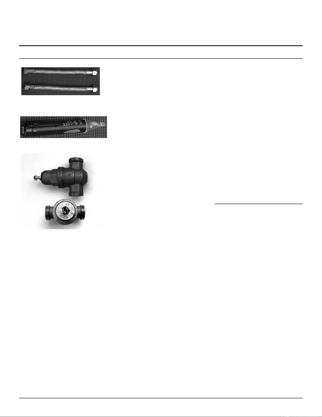
BEFORE YOU BEGIN
Figure 7. Flexible connectors use compression fittings
and do not require soldering.
Figure 8. Use a non-contact circuit tester to insure that
the power is off before you work on a circuit.
Figure 9. Install a Pressure Reducing Valve set to 50 to
60 PSI.
1. Review all of the instrucons before you
begin work.
Improper installaon can damage the
storage booster tank, your home and
other property, and can present risks of
serious injury or death.
2. This water heater is designed as a
Category I, non-direct vented water
heater which takes its combuson air
either from the installaon area or from
air ducted to the unit from the outside.
This water heater must be installed
according to all local and state/provincial
codes.
3. Check with your local and state
authories for any local or state codes
that apply to your area. In the absence
of local and state codes, follow Naonal
Fire Protecon Associaon (NFPA-70)
and the current edions of the Naonal
Electric Code (NEC) and the Internaonal
Plumbing Code (IPC). The instrucons
in this manual comply with naonal
codes, but the installer is responsible for
complying with local codes.
Note: If you lack the necessary skills required
to properly install this water heater,
or you have difficulty following the
instrucons, you should not proceed
but have a qualied person perform the
installaon of this water heater.
4. Before you start, be sure you have the
following tools and supplies:
• Common plumbing tools (depending
on what type of water pipes you
have).
• Thread sealant tape or pipe joint
compound approved for potable
water.
• For homes with copper pipes, you
may purchase a Gas Water Heater
Hook-Up Kit (available at your local
plumbing supplier) with compression
ngs that don’t require soldering.
This kit includes two 12” ex water
lines, two compression ngs, an
18” exible gas line, two nipples, and
thread sealant tape.
• For homes with plasc pipe, use
threaded connectors suitable for
the specic type of plasc pipe
used: CPVC or PEX (cross-linked
polyethylene). Do not use PVC pipe.
• A chloride-free liquid soluon
is the only approved fuel gas or
combuson product leak vericaon
method. .
• An appliance dolly or hand truck to
move the water heater.
RECOMMENDED ACCESSORIES:
• A metal drain pan.
• Automac water leak detecon and shut-
o device.
• Pressure Reducing Valve.
• Thermal Expansion Tank.
• Thermostac Mixing Valves at each point-
of-use.
• Fuel gas and carbon monoxide detector.
16 • Residential Condensing Gas Water Heaters
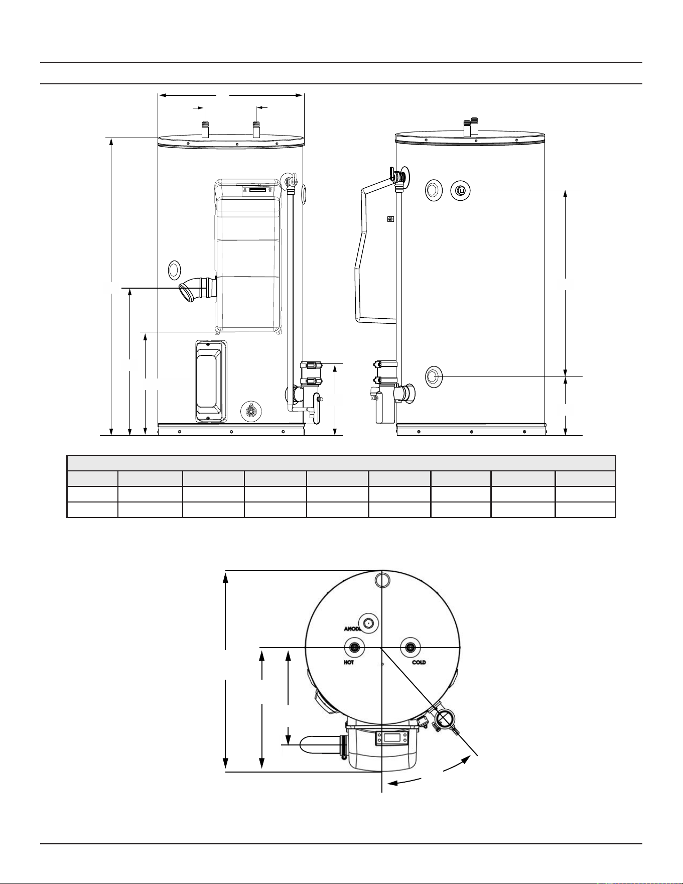
ROUGH-IN DIMENSIONS
H
G
A
B
D
C (Gas connection)
E
F
Figure 10. Rough-In Front- and Right-Side Views
Table 3. Rough-In Dimensions Key in Inches (centimeters)
Models A B C D E F G H
40 Gallon
45.00 (114.3) 22.38 (56.84) 15.75 (40) 10.5 (26.67) 27.75 (70.49) 8.75 (22.22) 22.00 (55.88) 8.00 (20.32)
50 Gallon
54.50 (138) 24.75 (62.86) 18.75 (47.62) 9.75 (24.76) 37.75 (95.89) 8.00 (20.32) 22.00 (55.88) 8.00 (20.32)
29 inches
(73.66 cm)
41°
13.5 inches
(34.29 cm)
17 inches
(43.2 cm)
Figure 11. Rough-In Top View
GETTING STARTED
Residenal Condensing Gas Water Heaters • 17
VERIFY THAT YOUR HOME IS EQUIPPED AND
UP-TO-DATE FOR PROPER OPERATION
Installing a new water heater is the perfect me
to examine your home’s plumbing system and
make sure the system is up to current code
standards. There have likely been plumbing
code changes since the old water heater
was installed. We recommend installing the
following accessories and any other needed
changes to bring your home up to the latest
code requirements. Updang your plumbing
system can help extend the life of your
water heater, avoid damage to your home
and property, and reduce the risk of serious
injuries or death. Inspect your home and install
any devices you need to comply with current
codes and assure that your new water heater
performs at its best. Check with your local
plumbing ocial for more informaon.
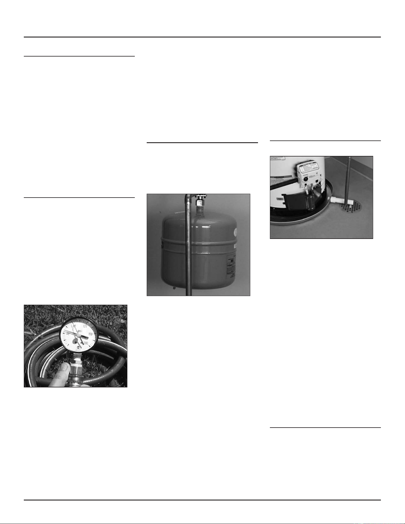
Water Pressure
Most codes allow a maximum incoming water
pressure of 80 psi (we recommend a working
pressure no higher than 50-60 psi). Check your
home’s water pressure gauge and adjust if
necessary. High water pressure can damage
the water heater, piping, and other appliances.
HOW: Purchase an inexpensive water pressure
gauge from your local plumbing supplier.
Connect the water pressure gauge to an outside
faucet and measure the maximum water
pressure experienced throughout a 24-hour
period (highest water pressures oen occur
at night).
Figure 12. Use a Water Pressure Gauge to make sure your
home’s water pressure is not too high.
To adjust your home’s water pressure: Locate
your home’s Pressure Reducing Valve (PRV) on
the main incoming (cold) water supply line and
adjust the water pressure control to between
50 and 60 psi. If your home does not have a
Pressure Reducing Valve, install a PRV on the
home’s main water supply line and set it to
between 50 and 60 psi. Pressure Reducing
Valves are available at your local plumbing
supplier.
BACKGROUND: Over the years, many ulies
have increased water supply pressures so
they can serve more homes. In some homes
today, pressures can exceed 100 psi. High
water pressures can damage water heaters,
causing premature leaks. If you have replaced
toilet valves, had a water leak, or had to repair
appliances connected to the plumbing system,
pay parcular aenon to your home’s water
pressure. When purchasing a PRV, make sure
the PRV has a built-in bypass.
Water Pressure Increase Caused by
Thermal Expansion
Verify that you have a properly sized Thermal
Expansion Tank. We recommend installing an
expansion tank if your home does not have one.
Plumbing codes require a properly pressurized,
properly sized Thermal Expansion Tank in
almost all homes.
Figure 13. A Thermal Expansion Tank helps protect the
home’s plumbing system from pressure spikes.
HOW: Connect the Thermal Expansion Tank
(available at your local plumbing supplier) to the
cold water supply line near the water heater.
The expansion tank contains a bladder and
an air charge. To work properly, the Thermal
Expansion Tank must be sized according to the
water heater’s tank capacity and pressurized
to match the home’s incoming water pressure.
Refer to the instrucons provided with the
Thermal Expansion Tank for installaon details.
BACKGROUND: Water expands when heated,
and the increased volume of water must have
a place to go, or thermal expansion will cause
large increases in water pressure (despite the
use of a Pressure Reducing Valve in the home’s
main water supply line). The Safe Drinking
Water Act of 1974 requires the use of back-ow
preventers and check valves to restrict water
from your home reentering the public water
system. Back-ow preventers are oen installed
in water meters and may not be readily visible.
As a result, most all plumbing systems today are
now “closed,” and almost all homes now need
a Thermal Expansion Tank.
A Thermal Expansion Tank is a praccal and
inexpensive way to help avoid damage to the
water heater, washing machine, dishwasher,
ice maker, and even toilet valves. If your toilet
occasionally runs for no apparent reason
(usually briefly at night), that may be due
to thermal expansion increasing the water
pressure temporarily.
Water Pipe and Tank Leaks
Figure 14. A metal drain pan piped to an adequate drain
can help protect flooring from leaks and drips.
Leaks from plumbing pipes or from the water
heater itself can damage property and could
cause a re risk.
• Install an automac leak detecon and
shut-o device (available at your local
plumbing supplier). These devices can
detect water leaks and can shut o the
water heater’s water supply if a leak
occurs. Install a metal drain pan (available
at your local plumbing supplier) under
the water heater to catch condensaon
or leaks from the piping connecons
or tank. Most codes require, and we
recommend, installing the water heater
in a metal drain pan that is piped to an
adequate drain. The drain pan must be at
least two inches wider than the diameter
of the water heater. Install the drain pan
so the water level would be limited to a
maximum depth of 1-¾”. The pan must
not restrict air ow to the burner.
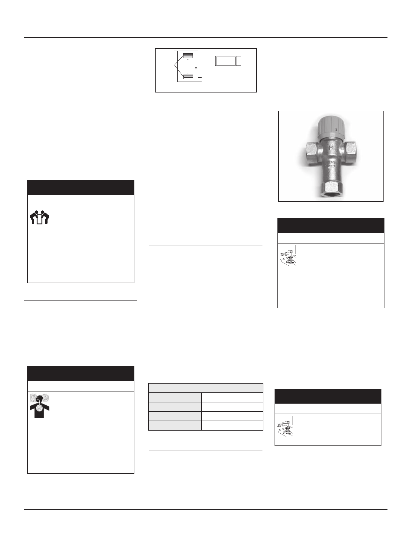
WATER TEMPERATURE REGULATION
Install Thermostac Mixing Valves to regulate
the temperature of the water supplied to
each point-of-use (for example, kitchen sink,
bathroom sink, bath, shower). Install and adjust
the mixing valve according to its manufacturer’s
instrucons..
GETTING STARTED
18 • Residenal Condensing Gas Water Heaters
The temperature of the water in
a water heater can exceed the
thermostat se�ng to the point of
being able to cause burns.
Even if the water heater’s thermostat is set
to a rela�vely low temperature, hot water
can scald. Install Thermosta�c Mixing
Valves at each point-of-use to reduce the
risk of scalding.
Burn Hazard
⚠
WARNING
See Table 1 (page 6).
Figure 15. Thermostatic Mixing Valves installed at each
point-of-use can help avoid scalding.
BACKGROUND: A Thermostac Mixing Valve,
installed at each point-of-use, mixes hot water
from the water heater with cold water to more
precisely regulate the temperature of hot water
supplied to xtures. If you are not sure if your
plumbing system is equipped with properly
installed and adjusted Thermostatic Mixing
Valves at each point where hot water is used,
contact a qualied person.
VERIFY THAT THE LOCATION IS
APPROPRIATE
Flammable vapors can leak from
their containers and be ignited by
the water heater. The resul�ng fire
and/or explosion can cause serious
injury or death.
Do the following to avoid this hazard:
• Do not place chemical vapor emitting
products near air intake and exhaust
terminations.
• Do not use or store flammable vapor
products, such as gasoline, solvents, or
adhesives in the same room or area near
the water heater or other appliances.
Fire and Explosion Hazard
WARNING
⚠
Over �me, the tank and fi�ngs of
the water heater can begin to leak
and cause water damage.
Locate the water heater in an
area where water leakage from
the heater or connec�ons will not result in
damage to the area or the lower floors of
the structure.
Property Damage Hazard
⚠
CAUTION
Carefully choose a locaon for the new water
heater. The placement is a very important
consideraon for the safety of the occupants in
the building and for the most economical use
of the water heater.
Whether replacing an exisng water heater or
installing the water heater in a new locaon
observe the following crical points:
1. The water heater must be located
indoors.
2. The water heater must not be located
in an area where it will be subject to
freezing temperatures.
3. Locate the water heater so it is protected
and not subject to physical damage by
a moving vehicle. In garage installaon
avoid damage to your water heater by
installing a vehicle stop as shown in
Figure 16. Check state and local codes for
requirements prior to installaon.
Figure 16. Garage Installation
4. Locate the water heater on a level
surface.
5. Locate the water heater near a oor
drain. The water heater should be
located in an area where leakage of
the tank or connecons will not result
in damage to the area adjacent to the
water heater or to lower oors of the
structure. When such locaons cannot
be avoided, it is recommended that
a metal drain pan, piped to adequate
drain, be installed under the water
heater. Drain pan should be fabricated
with sides at least 45 mm (1-3/4”)
deep with diameter at least 50 mm (2”)
greater than diameter of heater. Pan
must not restrict combuson air ow.
6. Locate the water heater close to the
point of major hot water usage.
7. Locate the water heater close to a 120
Vac power supply. See Electrical Supply
(page 39) for requirements.
8. Locate the water heater where an
adequate supply of fresh air for
combuson and venlaon can be
obtained. See Combustion Air and
Ventilation (page 21).
9. Locate the water heater where the vent
and intake air piping, when installed, will
remain within the maximum equivalent
lengths allowed. See Combustion Air and
Ventilation (page 21).
10. Do not locate the water heater where
noise (such as the Combuson Blower)
during normal operaon will be
objeconable in adjacent areas.
11. Do not locate the water heater where
the subsequent installaon of the vent
(exhaust) or intake air terminaons
would be objeconable due to noise
at the terminaon(s). This includes
locaons close to or across from
windows and doors. See Power Direct
Venting (PDV) (page 25) and Power
Vent (PV) (page 31).
Under certain circumstances, the
water heater can explode and catch
fire, resul�ng in property damage,
personal injury, or death.
Do the following to avoid these
condi�ons:
• Do not store or use gasoline or other
flammable vapors and liquids in the vicinity
of this or any other appliance.
• Avoid all ignition sources if you smell gas.
• Do not expose water heater controls to
excessive gas pressure.
• Use only the gas shown on the water
heater rating label.
• Maintain required clearances to
combustibles.
• Keep ignition sources away from faucets
after extended periods of non-use.
• Install sediment trap in accordance with
NFPA54
or
CSA-B1491.
• Read the instruction manual before
installing, using, or servicing the water
heater.
• Contact a qualified installer or service
agency for installation and service.
Fire and Explosion Hazard
⚠
WARNING
GETTING STARTED
Residenal Condensing Gas Water Heaters • 19
Do not locate water heater areas where
flammable liquids (vapors) are likely to be
present or stored (garages, storage and
ulity areas, etc.): Flammable liquids (such as
gasoline, solvents, propane (LP or butane, etc.))
and other substances (such as adhesives, open
paint cans etc.) emit ammable vapors which
can be ignited by a gas water heater’s ignion
device or main burner. The resulng ashback
and re can cause death or serious burns to
anyone in the area.
Installation: Do not install the water heater where flammable
products will be stored or used.
Vapors from flammable
liquids may explode and
catch fire causing death or
severe burns.
Do not use or store
flammable products such as
gasoline, solvents or
adhesives in the same room
or area near the water
heater.
Keep flammable products:
1. far away from heater,
2. in approved containers,
3. tightly closed and
4. out of children's reach.
Water heater has a main
burner and hot surface
igniter. The hot surface
igniter:
1. can be triggered at any
time and
2. the hot surface will ignite
flammable vapors.
Vapors:
1. cannot be seen,
2. are heavier than air,
3. go a long way on the
floor and
4. can be carried from other
rooms to the electrodes
by air currents.
Flammable Vapors
FLAMMBLE
WARNING
When the water heater is installed directly on
carpeng, the water heater shall be installed on
a metal or wood panel extending beyond the
full width and depth of the water heater by at
least 3” in any direcon or, if the water heater
is installed in an alcove or closet, the enre
oor shall be covered by the panel. The panel
must be strong enough to carry the weight of
the heater when full of water.
Installing the water heater too
close to combus�ble materials
can result in a fire resul�ng in
property damage, serious injury,
or death.
Maintain minimum required clearances
to combus�bles.
Fire Hazard
⚠
WARNING
Minimum clearances from combustible
materials are stated on the data plate located
on the front of the water heater. Standard
clearances are 0” at the sides and rear, 0”
from the front, and 0” from the top. If the
clearances from combusble material stated
on the water heater dier from the standard
clearances, install the water heater according
to the clearances stated on the water heater.
Adequate clearance for inspecon and service
should be considered before installation. A
minimum of 24” of front clearance and 4” on
each side should be provided for access to
replaceable and/or serviceable parts such as
drain valve, condensate drain, temperature-
pressure relief valve, and the vent connecon
(exhaust tee).
Figure 17 may be used as a reference guide to
locate the specic clearance locaons. When
installing the water heater, consideration
must be given to proper locaon. The locaon
selected should be as close to the wall as
praccable and as centralized with the water
piping system as possible.
CEILING
FRONT VIEW
0”
(0 mm)
MIN.
0”
(0 mm)
MIN.
*4”
(102 mm)
MIN.
*For service access
LEFT
WALL
RIGHT
WALL
TOP VIEW
OF CLOSET
WITHOUT DOOR
WATER
HEATER
0”
(0 mm) MIN.
0”
(0 mm) MIN.
*24”
(610 mm) MIN.
TOP VIEW
OF CLOSET
WITH DOOR
WATER
HEATER
Figure 17. Clearance Locations
REMOVING THE OLD WATER HEATER
1. Read each installaon step and decide
if you have the necessary skills to install
the water heater. Only proceed if you are
comfortable you can safely perform the
work. If you are not sure, have a qualied
person perform the installaon.
2. Follow the direcons in the manual that
came with your old water heater for
shung it down.
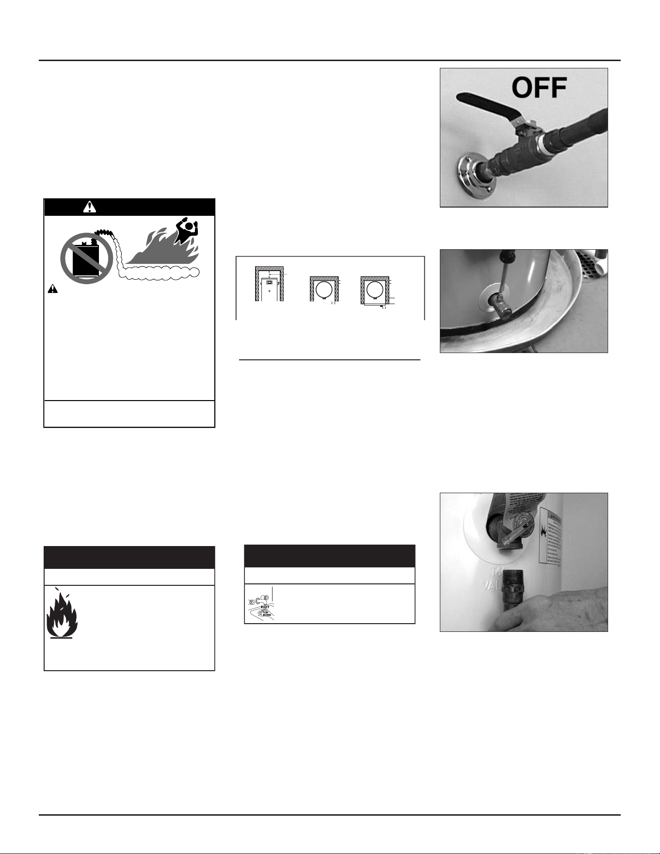
3. If the old water heater is a gas water
heater, turn the manual gas valve for the
water heater’s gas supply line to OFF.
4. Open a hot water faucet and let the hot
water run unl it is cool.
Be sure the water runs cool before
draining the tank to reduce the risk
of scalding.
Burn Hazard
⚠
WARNING
5. Connect a garden hose to the drain valve
and place the other end of the hose in a
drain, outside, or in buckets (sediment
in the boom of the tank may clog the
valve and prevent it from draining. If you
cannot get the tank to drain, contact a
qualied person).
6. Turn the cold water supply valve OFF.
Figure 18. Cold water supply in OFF position.
7. Open the drain valve on the water heater.
Figure 19. Draining the old water heater.
8. Also open a hot water faucet to help the
water in the tank drain faster.
9. When the tank is empty, disconnect the
Temperature & Pressure (T&P) Relief
Valve discharge pipe. You may be able
to reuse the discharge pipe, but do not
reuse the old T&P Relief Valve. A new T&P
Relief Valve comes with your new water
heater.
Figure 20. Removing the T&P Relief Valve discharge pipe.
10. If the old water heater is a gas water
heater and has either a dra hood or vent
piping, ensure that the components are
cool and then disconnect them according
to the manual that came with the water
heater. You may need to support the vent
piping unl the new water heater is in
place.
11. If the water heater has input air ducng,
disconnect the water heater at the input
air connecon ng.
GETTING STARTED
20 • Residenal Condensing Gas Water Heaters
12. Disconnect the water pipes. In many
cases, the water pipes are connected
by a threaded union, which can be
disconnected with wrenches. If you must
cut the water pipes, cut the pipes close
to the water heater’s inlet and outlet
connecons, leaving the water pipes as
long as possible. If necessary, you can
make them shorter later when you install
the new water heater.
13. If the water heater is a gas water heater,
conrm that the manual gas valve for the
water heater’s supply line is turned OFF.
Disconnect the gas line from the water
heater’s gas control valve and cap it.
14. Remove the old water heater. Use an
appliance dolly or hand truck to move the
water heater.
This water heater is too heavy to
be carried safely by one person.
A�emp�ng to do so could cause
serious injury.
Avoid this hazard by doing the following:
• Use at least two people to lift the water
heater.
• Be sure you both have a good grip before
lifting.
•
Use an appliance dolly or hand truck to move
the water heater.
Li Hazard
WARNING
⚠
COMBUSTION AIR AND VENTILATION
A gas water heater cannot operate properly
without the correct amount of air for
combustion. Never obstruct the flow of
ventilation air. If you have any doubts or
quesons at all, call your gas supplier. Failure to
provide the proper amount of combuson air
can result in a re or explosion and cause death,
serious bodily injury, or property damage.
An improperly installed water
heater can emit carbon monoxide.
Breathing carbon monoxide can
cause brain damage or death.
Do the following to avoid carbon monoxide
poisoning:
• Install the water heater in accordance with
the instruction manual and NFPA 54.
• To avoid injury, combustion and ventilation
air must be taken from outdoors.
• Do not place chemical vapor emitting
products near water heater.
Breathing Hazard-Carbon Monoxide Gas
⚠
WARNING
VENTILATION
AIR
OPENING
12” max.
(30.5 cm)
12” max.
(30.5 cm)
100 sq in
(645 sq cm)
FRONT VIEW OF DOOR
3”
(7.6 cm)
Rectangular
Air Duct
Figure 21. Closet Door Ventilation
Propellants of aerosol sprays and volatile
compounds, (cleaners, chlorine based
chemicals, refrigerants, etc.) in addition to
being highly ammable in many cases, will also
react to form corrosive acids when exposed
to the combustion products of the water
heater. The results can be hazardous, and also
cause product failure. Air for combuson and
venlaon must not come from a corrosive
atmosphere. Any failure due to corrosive
elements in the atmosphere is excluded from
warranty coverage.
It is imperative that the water heater(s)
be installed direct vent so that all air for
combustion and ventilation is taken from
outdoors.
CORROSION AND WATER QUALITY
Water quality will vary from locaon to locaon
and may contain contaminates that can reduce
the life or performance of the water heater.
Contaminates which can reduce the life or
performance of the water heater, if present in
high quanes, include those which contribute
to hardness (dissolved minerals such as sodium,
calcium and magnesium); plus chlorides and
sulfates. Addionally, water that is too acidic
or alkaline (measured as pH) can reduce the
life of the water heater. Water treatment
systems (such as water soeners for hardness)
should be used and maintained properly if the
contaminate levels exceed the following:
Warranty is void in applicaons which exceed
the water quality requirements listed below.
Table 4. Water Quality Requirements
Total Hardness
12 grains per gal. max.
Chloride
12 grains per gal. max.
pH
6.5-8.0
Alkalinity
12 grains per gal. max.
INSTALL SHUT-OFF AND THERMOSTATIC
MIXING VALVES
1. If one is not already installed, install a
manual shut-o valve in the cold water
line that supplies the water heater. Install
the shut-o valve near the water heater
so that it is readily accessible. Only use
a full-ow ball or gate valve compable
with potable water.
2. Install a Thermostac Mixing Valve at
each point-of-use (for example, kitchen
sink, bathroom sink, bath, shower) per
the valve manufacturer’s instrucons.
Figure 22. Install Thermostatic Mixing Valves at each
point where hot water will be used.
The temperature of the water in
a water heater can exceed the
thermostat se�ng to the point of
being able to cause burns.
Even if the water heater’s thermostat is set
to a rela�vely low temperature, hot water
can scald. Install Thermosta�c Mixing
Valves at each point-of-use to reduce the
risk of scalding.
Burn Hazard
⚠
WARNING
3. For water heaters that are fed by a solar
water heang system (or any other
pre-heang system), always install a
Thermostac Mixing Valve or other
temperature liming device in the inlet
water supply line to limit water supply
inlet temperature to 120°F. Solar water
heang systems can supply water with
temperatures exceeding 180°F and may
result in water heater malfuncon.
Hot water provided by solar hea�ng
systems can cause severe burns
instantly, resul�ng in serious injury
or death.
Burn Hazard
⚠
WARNING
.
GETTING STARTED
Residenal Condensing Gas Water Heaters • 21
INSTALLING THE VENT SYSTEM
PLANNING THE VENT SYSTEM
This water heater may be installed in either
a Power Direct Vent (PDV) or in a Power Vent
(PV) conguraon. Both conguraons must be
properly vented for removal of exhaust gases to
the outside atmosphere. Correct installaon of
the vent pipe system is mandatory for the safe
and ecient operaon of this water heater and
is an important factor in the life of the unit.
This water heater, when installed in a PDV
conguraon, has a direct vent system in which
all combustion products (exhaust) must be
vented to the outdoors and will require outdoor
air for combuson. Both intake and exhaust
piping will require a sealed piping system as
described in these instrucons.
When installed in a Power Vent (PV)
conguraon, this water heater will require
room air for combuson. Adequate air intake
resources are required. The exhaust piping will
require a sealed piping system as described in
these instrucons.
Improper installa�on use and
service could result in property
damage.
This unit must be configured with both an
air intake terminal and an exhaust
terminal.
Property Damage Hazard
⚠
CAUTION
Certain abnormal condi�ons can
cause the water heater to emit
carbon monoxide. Breathing carbon
monoxide can cause brain damage
or death.
Do the following to prevent these
abnormal condi�ons:
• Do not operate water heater if any part has
been exposed to flooding or water damage.
• Do not operate if soot buildup is present.
• Do not obstruct water heater air intake with
insulating jacket.
• Do not place chemical vapor emitting
products near water heater.
• Never operate the heater unless it is vented
to the outdoors and has adequate air supply
to avoid risks of improper operation, fire,
explosion, or asphyxiation.
• Always read and understand the instruction
manual.
• Install gas and carbon monoxide detectors in
the vicinity of the water heater.
Breathing Hazard-Carbon Monoxide Gas
⚠
WARNING
Important: This water heater must be
vented separately from all
other appliances. DO NOT
common vent this water
heater with any other
appliance. DO NOT vent into a
common chimney.
Table 5 (page 23) lists the allowable vent
materials. Figure 36, Figure 37, and Figure 38
(page 29) show various end termination
details and clearances for PDV installaons.
Figure 42, Figure 43, and Figure 44 (page 33)
shows various end termination details and
clearances for PV installaons
Note: The informaon provided in Figure 3 is
intended as a guideline for good vent
installaon pracces only.
This water heater may be vented horizontally
through a wall or vercally through the roof.
Pipe runs must be adequately supported along
both vertical and horizontal runs according
to local codes or the venng manufacturer’s
instrucons such as IPEX (www.ipexna.com/
resources/technical-library).
Note: Do not use an elbow as a support point.
Elbows are not designed to carry the
load or stresses of the venng system
if they are rigidly held.
Note: Do not use the condensaon trap as a
support point. It not designed to carry
the load or stresses of the venting
system. Vent piping must be supported
adequately and not put any weight on
the condensaon trap.
Vent pipe must be installed in accordance
with all local codes or, in the absence of
such, the latest edion of National Fuel Gas
Code, ANSI Z223.1/NFPA 54. In addition,
clearances from combusble materials must be
provided in accordance with informaon in the
“Locating The New Water Heater” secon of this
manual. Take note of the clearance and venng
requirements when installing in a confined
space such as a small room or closet. Vent pipes
serving power vented appliances are classied
by building codes as “vent connectors”.
• Plan the vent system layout so that proper
clearances are maintained from plumbing
and wiring.
• Plan the layout of the vent system from
the vent terminaon to the water heater
considering all the elbows (90° and 45°)
plus the number of feet of pipe that will
be needed to install the total vent system.
• Venng should be as direct as possible
with the fewest number of ngs.
• Use long radius 45° and long radius 90°
elbows wherever possible.
• Avoid using 90° elbows “back to back”
and do not use street elbows.
• Maintain a minimum 6” straight secon
between elbows. Closely coupled and
short radius elbows reduce the venng
capacity. Figure 24 (page 23) shows
examples of vent pipe connecons.
An improperly installed water
heater can emit carbon monoxide.
Breathing carbon monoxide can
cause brain damage or death.
Do the following to avoid carbon monoxide
poisoning:
• Install the water heater in accordance with
the instruction manual and NFPA 54.
• To avoid injury, combustion and ventilation
air must be taken from outdoors.
• Do not place chemical vapor emitting
products near water heater.
Breathing Hazard-Carbon Monoxide Gas
⚠
WARNING
VENT KIT
A Vent Kit included with this water heater
may be used for standard sidewall or roof
terminaon. It consists of:
1. One 45° ULC PVC elbow for installaon
on exhaust venng,
2. One 45° ULC PVC elbow for installaon
on air intake venng,
3. Wire mesh screens for installaon on
the intake and outlet terminaons
to prevent objects from blocking the
venng system. See Vent Screens (page
24).
4. 2” Dia x 3.00”L PVC Pipe for connecon
to blower intake in PV (Power Vent)
installaons.
5. 2” rubber coupling for connecons to
condensate/exhaust tee.
6. Condensate/Exhaust tee.
7. Outlet pressure switch so tubing for
connecon to Condensate/Exhaust tee.
Debris screens are to be installed at the
terminaons to keep foreign materials out of
the venng.
22 • Residential Condensing Gas Water Heaters
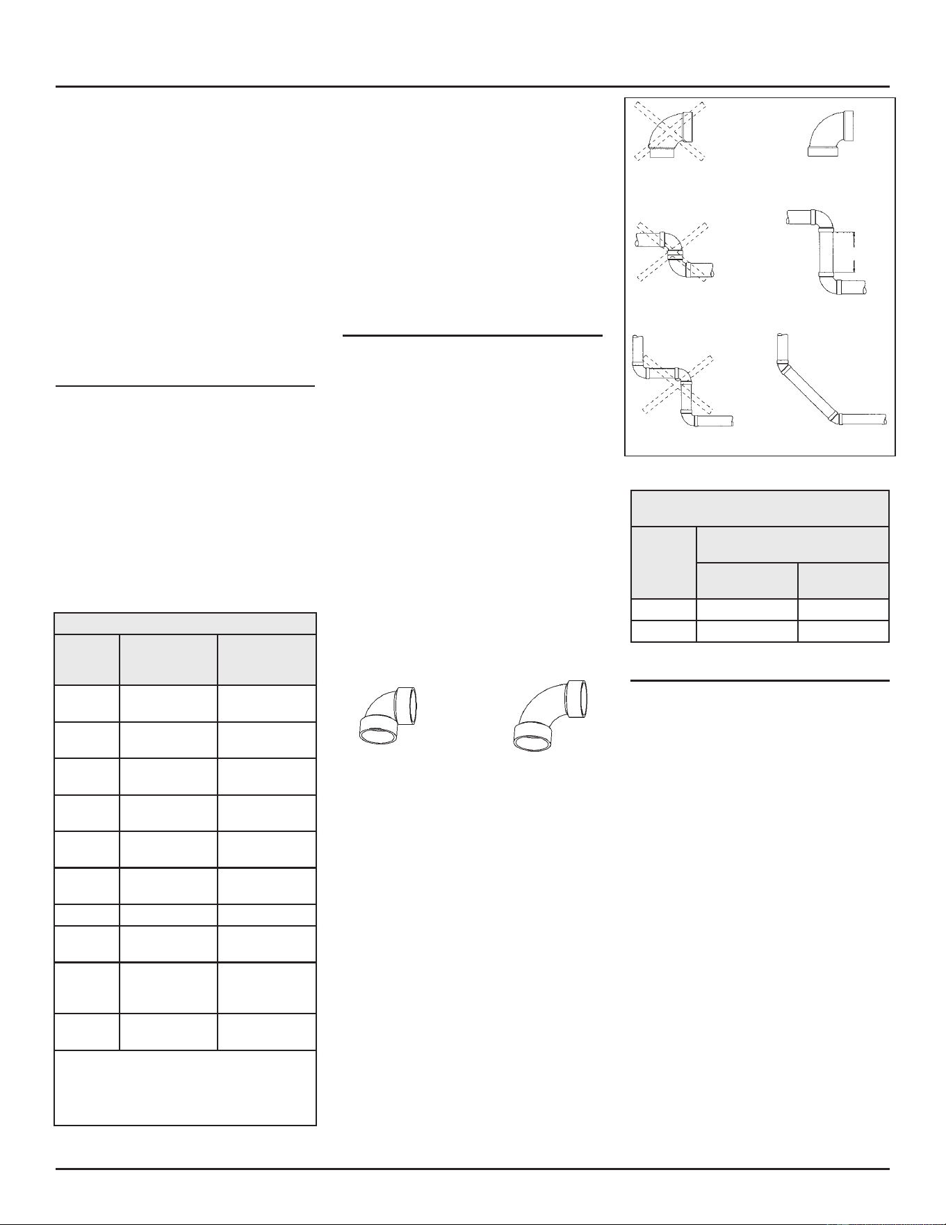
Note: The Condensate/Exhaust tee and outlet
pressure switch tubing will need to be
connected to the water heater before
the exhaust venng can be connected
to the water heater. See Installing the
Exhaust/Condensate Tee (page 24).
Additional vent termination options (not
included) are available. Instrucon for installing
these other terminaon methods are described
later in this secon.
Important: Aer compleng the venng
installaon, ensure the
vent pipe is not blocked or
restricted in any way.
VENT PIPE MATERIAL
This heater is cered to be installed using
Schedule 40 vent material. Check local codes
to determine which materials are allowed in
your area and only use approved material.
All venng material and components must be
joined with the approved primer/cleaner and
solvent cement. Do not cement the venng
system to the heater. For polypropylene vent
systems follow manufacturer’s instrucons.
Note: Polypropylene vent systems require
separate adaptor, termination, and
elbows (eld supplied).
Table 5. Vent Pipe Materials
Material
Pipe and
Fitting
Nomenclature
Applicable
Standard
PVC DWV ASTM D2665 or
CSA B181.2
PVC Sch 40, 80, 120 ASTM D1785 or
CSA B137.3
PVC SDR series ASTM D2241 or
CSA B137.3
PVC BH ULC S636‡
UL 1738§
CPVC CPVC 41 ASTM D2846 or
CSA B137.6
CPVC Sch 40, 80 ASTM F441 or
CSA B137.6
CPVC SDR series ASTM-F442
CPVC BH ULC S636‡
UL 1738§
ABS Sch 40 DWV ASTM D2661§,
CSA B181.1§ or
ULC S636‡
Polypro-
pylene
n/a ULC S636‡
UL 1738§
‡ Applicable to Canada only.
§ Applicable to the United States only.
Use of cellular core PVC (ASTM F891), cellular core CPVC,
or Radel®(polyphenysulfone) in non-metallic venng
systems is prohibited.
Important: Use only solid (not foam core)
piping. Plasc pipe and ngs
are available through most
plumbing suppliers. Always
check the marking on the pipe
to make sure you are using
the correct material. Use of
cellular core PVC (ASTM F891),
cellular core CPVC, or Radel
®
(polyphenolsulfone) in non-
metallic venng systems is
prohibited.
VENT PIPE LENGTH AND SIZING
See Table 11 (page 30), and Table 14 (page
34) for vent pipe sizing. If the installation
requires a vent riser, suitable drainage must
be provided to ensure condensaon does not
accumulate. See Figure 45 (page 34). The
specied maximum lengths are for each of the
intake and exhaust systems and not for the
combined lengths of both systems. Minimum
pipe length is 2’ with a minimum of one 90°
elbow per side (intake and exhaust).
1. Determine terminaon type and pipe
size.
2. Determine number of elbows in vent
system. Do not include terminaon
elbow. Calculate the maximum equivalent
length of the exhaust and air intake
system using Table 6 to determine
equivalent length values.
90° LONG SWEEP ELBOW
(LESS RESTRICTIVE)
90° SHORT SWEEP ELBOW
(MORE RESTRICTIVE)
Figure 23. Vent Pipe Elbows
STREET ELBOW
NORMAL ELBOW
BACK TO BACK ELBOWS
150 mm (6”) minimum
PREFERRED PRACTIICE
Figure 24. Vent Pipe Elbow Use
Table 6. Elbow Type and Equivalent
Lengths of Straight Pipe
Elbow
Type
Equivalent Length Of Straight
Pipe
Short Sweep/
Radius
Long Sweep/
Radius
90° 8’ 5’
45° 4’ 2.5’
POLYPROPYLENE VENT SYSTEMS
Note: This heater is cered to use solid wall
polypropylene venng. Do not install
with the corrugated type ex venng.
Polypropylene vent systems do not use cement
to connect the pipe and elbow secons but
use a push together gasket seal method. Do
not aempt to connect polypropylene with
sealant cement.
• Polypropylene vent systems are designed
to use specic adaptors to connect the
water heater venng. These adaptors are
available through your venng supplier.
• The PVC vent terminaon elbow supplied
with this heater has been cered to be
used with polypropylene vent systems.
A polypropylene to PVC end connecon
is required and is available through your
venng supplier.
• Oponal wall plates that t the
polypropylene venng are also available
through your supplier.
INSTALLING THE VENT SYSTEM
Residenal Condensing Gas Water Heaters • 23
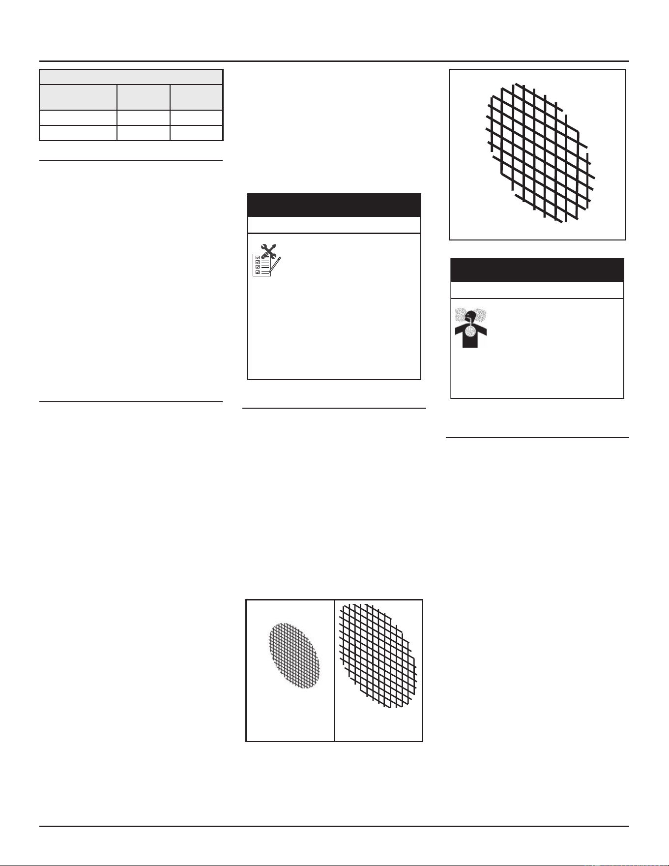
Table 7. Pressure Switch Settings
Pressure Switch
Setting (NC) Nat Gas LP Gas
Outlet Air (OAPS) 1.8” w.c. 1.43” w.c.
Intake Air (IAPS) -1.88” w.c. -1.62” w.c.
Vent Pipe Runs
1. The exhaust vent system must not,
under any circumstances, be run
downhill then run uphill thus forming
a valley. It may leave a space to
accumulate condensaon and block vent
pipe.
2. Horizontal runs require a minimum 1/8”
rise per 5’ and a support according to
venng manufacturer’s instrucons.
Ensure there is enough height between
heater and terminaon to raise vent
pipe runs the required distance.
3. Vercal runs must provide proper
support to prevent stress on the pipes
according to venng manufacturer’s
instrucons.
VENT PIPE INSTALLATION
The following guidelines should be followed
when installing the air intake and exhaust vent
system:
• Vent diameter must not be reduced
unless specically noted in the installaon
instrucons.
• Support all horizontal pipe runs
according to local codes or the venng
manufacturer’s instrucons such as IPEX
(www.ipexna.com/resources/technical-
library).
• Covering non-metalic vent piping with
thermal insulaon is prohibited.
• Vents run through uncondioned spaces
where below freezing temperatures are
expected, are not recommended.
• Vents run through uncondioned spaces
inside a building may result in the
condensaon of ue gases during the
winter season.
Venng Instrucons
1. Calculate “Equivalent Vent Length” before
starng. Do not exceed the values shown
in Table 11 (page 30), and Table 14
(page 34).
2. Follow the vent manufacturer’s
instrucons for installing the venng.
3. Install the properly sized debris screen
into the outlet elbow and secure with a
small quanty of silicone sealant.
4. Do not seal the vent piping to the wall
unl the venng is properly connected to
the condensate trap assembly.
5. Complete the venng installaon by
sealing around the terminaon assembly
where it passes through the outside wall,
inside and out, with silicone or other
suitable sealant. Apply enough sealant to
secure the (oponal) cover plate to the
wall.
Solvent cements and primers
for plastic pipe are flammable
liquids and emit flammable
vapors. Improper use can cause
an explosion and fire that would
result in property damage.
• Use only in well ventilated areas.
• Do not use near any open flame and all
ignition sources, including water heaters.
•
Use only the solvent cement and primer
appropriate for the venting material being
used.
Property Damage Hazard
⚠
CAUTION
VENT SCREENS
Installed in the intake and vent terminaon
elbows, the debris vent screen is required to
keep foreign objects, rodents and small birds
from entering the venng system. Any such
debris can acvate the Blocked Air sensors and
prevent the water heater from operang.
• Install the debris vent screen in both the
air intake pipe and the exhaust pipe.
• Gently push the screen into the
terminaon elbow unl it sits against the
inside shoulder.
• The debris vent screens are self-securing.
Note: In the concentric vent applicaon, the
vent screen is to be installed in the
exhaust piping only.
2” Vent piping
2.45 in. O. D.
(6.22 cm O.D.)
3” Vent piping
(3.56 in. O. D.
(9.04 cm O.D.)
4” Vent piping; 4.50 in. O. D.; (11.43 cm O.D)
Figure 25. Termination Debris Screen
Installing the vent screen
improperly or installing the
wrong screen can cause the water
heater to emit carbon monoxide.
Breathing carbon monoxide can
cause brain damage or death.
Install the appropriate screen designed for
this water heater according to the manual
and all applicable codes.
Breathing Hazard-Carbon Monoxide Gas
⚠
WARNING
INSTALLING THE EXHAUST/CONDENSATE
TEE
Before the exhaust vent system can be installed
the factory supplied Exhaust/Condensate Tee
must be installed on the water heater. See Vent
Kit for parts. See Figure 26.
1. Remove the Exhaust/Condensate Tee and
so tubing from the vent kit.
2. Aach the Exhaust/Condensate Tee to the
heaters exhaust rubber coupling located
at boom right of water heater. Note
orientaon.
3. Tighten the hose clamp to 24-30 in/Lbs.
4. Aach one end of the so tubing to
the hose barb located on the Exhaust/
Condensate Tee.
5. Aach the other end of the so tubing
to the aluminum tubing aached to the
water heater. This aluminum tubing is
connected to the Outlet Air Pressure
Switch, located on the control panel.
Note: The Exhaust/Condensate Tee must be
connected to the Outlet Air Pressure
INSTALLING THE VENT SYSTEM
24 • Residenal Condensing Gas Water Heaters
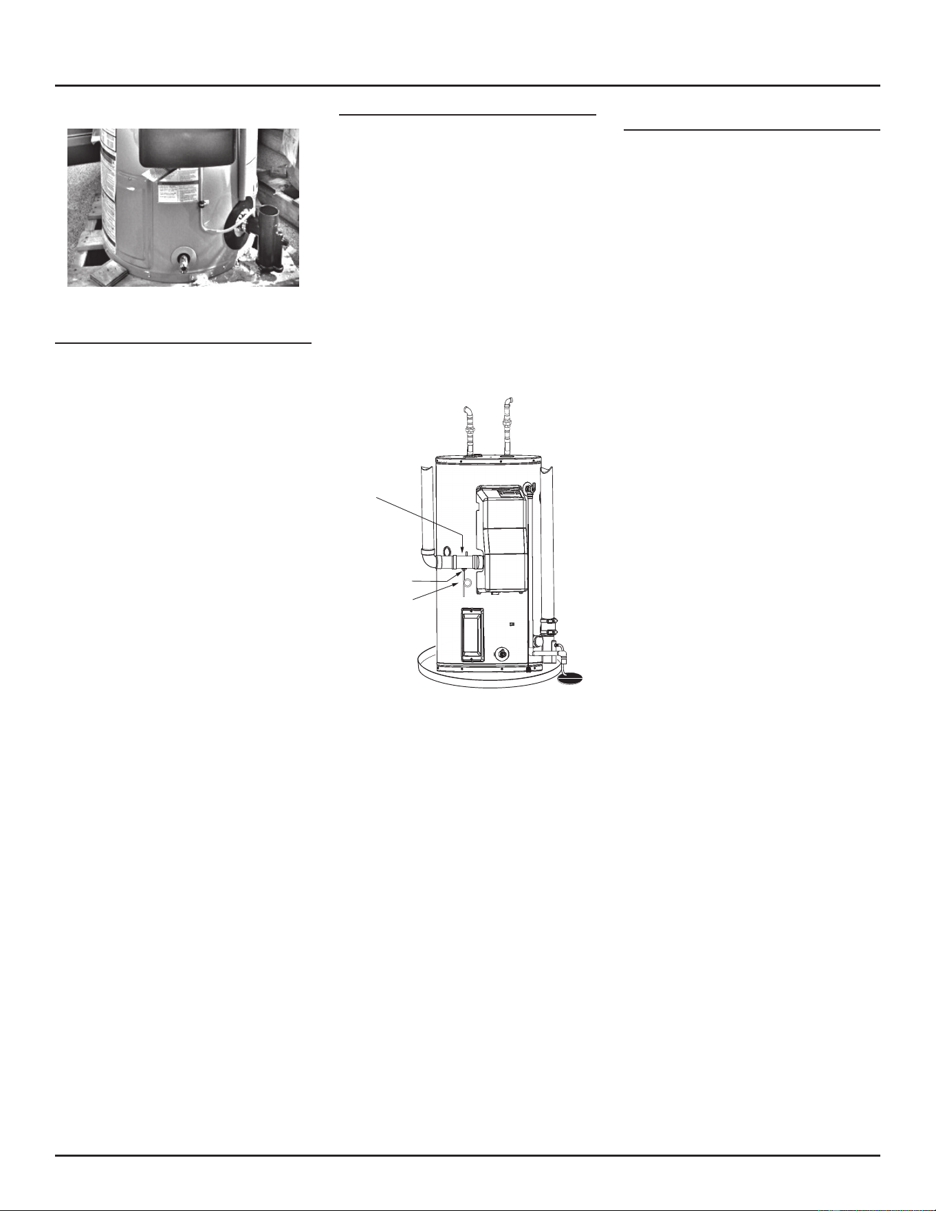
Switch or the OAPS will not funcon
properly.
Figure 26. Condensate/Exhaust Tee Installation
IMPORTANT NOTES AND WARNINGS
• Do not allow insulaon to cover the vent
piping.
• During operaon the plasc piping will
expand as it heats up and contract as it
cools down. This is normal for this type of
venng. Rigidly fastening the vent piping
can cause undue stress that may result
in the cracking or fracturing the vent
piping material. A fracture of the venng
pipe may pose a serious safety hazard. To
prevent stressing of the vent system, all
hangers and supports must allow the vent
piping freedom to move.
• All power vented water heaters generate
a certain amount of operaonal noise. In
order to minimize noise transmission to
the support structure, use isolaon pads
between the pipe hangers and the vent
pipe.
POWER DIRECT VENTING (PDV)
The combuson air intake and exhaust vent
system and terminaon may be installed in one
of the following type terminaons:
1. Horizontal (2 Pipe) (air intake and
exhaust vent).
2. Vercal (2 Pipe) (air intake and exhaust
vent)
3. Concentric (horizontal/side wall
installaon).
4. Concentric (vercal/roof installaon).
5. Low Prole (2 Pipe) (air intake and
exhaust vent). Horizontal use only.
CONNECT FIELD
SUPPLIED FLEXIBLE
DRAIN HOSE TO BARB
FITTING AND FORM A
LOOP WATER TRAP IN
DRAIN HOSE
RUN DRAIN HOSE
TO SUITABLE FLOOR
DRAIN SEPARATELY
FROM OTHER
CONDENSATE DRAINS
FIELD SUPPLIED
2” x 2” x 1/2” TEE
WITH HOSE BARB
FITTING INSTALLED
FACTORY-SUPPLIED
INTAKE AIR
CONNECTION
INSTALL TEE FITTING AS CLOSE
TO WATER HEATER
INTAKE AIR CONNECTION AS
POSSIBLE
Figure 27. Intake Air Condensate Tee Installation
DIRECT VENT AIR INTAKE MOISTURE PRO-
TECTION
The air intake piping in a direct vent system will
normally not have any moisture accumulaon in
it. However, in certain cases, moisture may build
up and needs to be drained. Typical situaons
include, but are not limited to:
• Cold outdoor temperature, parcularly if
the air inlet is short
• Heater being used mostly for space
heang
• Air inlet pipe has vercal rise near the
heater
Installaons with any of these condions are
required to provide a moisture drain with a
trap that ows to a waste drain. See Figure 27.
A horizontal secon of the air inlet pipe, near
the heater should include a 2”x 2” x 1/2” tee and
a hose barb ng to drain the water. The tee
should be as close to the heater as is praccal.
The drain tubing in any installation should
have a loop trap and ow to an appropriate
waste drain. The air intake drain line must be
enrely separate from the exhaust vent outlet
condensate line.
INSTALLING THE VENT SYSTEM
Residenal Condensing Gas Water Heaters • 25
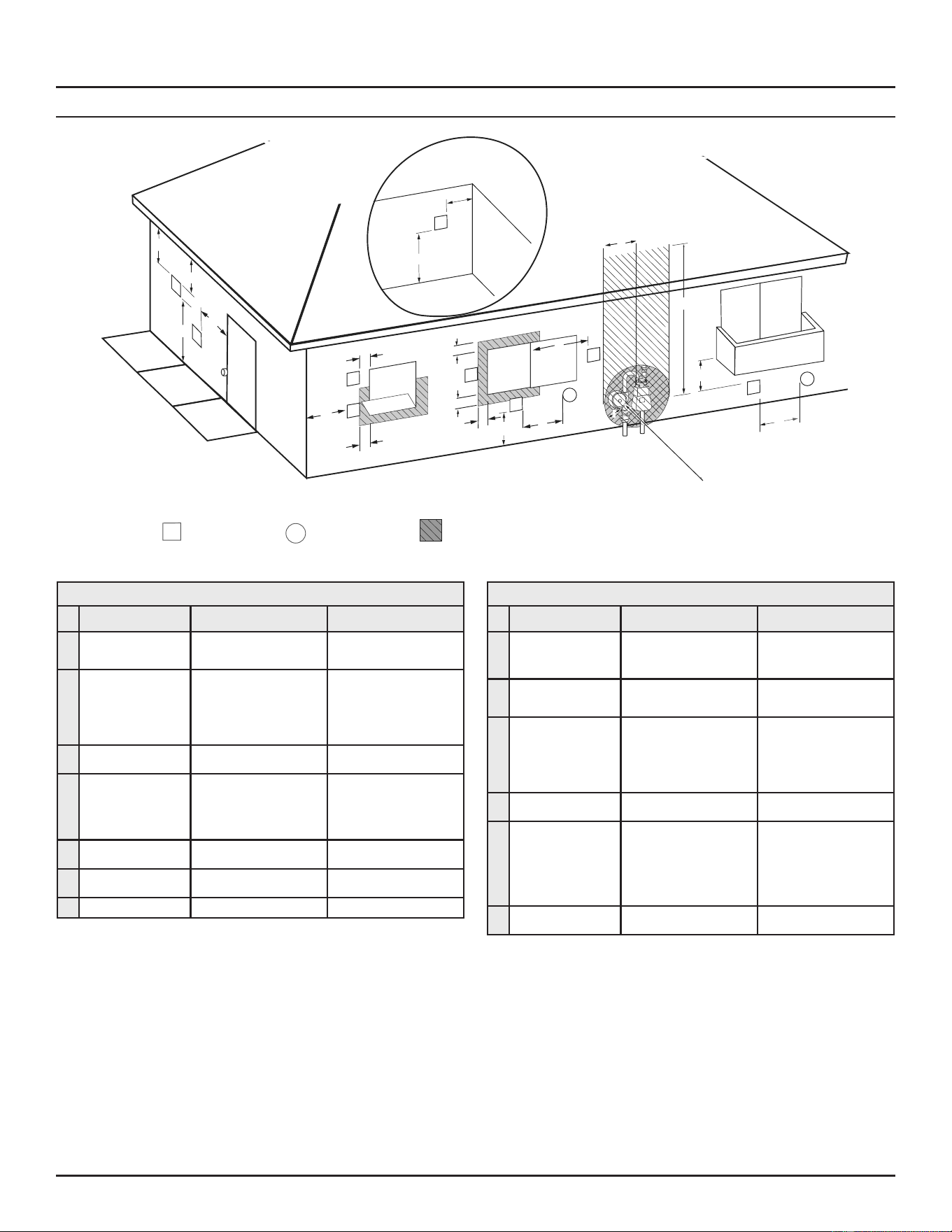
TERMINATION CLEARANCES SIDEWALL POWER VENT
Fixed
Closed
Operable
Fixed
closed
Operable
B
V
V
V
V
V
V
V
V
C
B
B
X
A
M
K
Regulator vent outlet
In the event no
regulator is present,
H and I can be
disregarded
.
V
Legend:
= Vent terminal
X
= Air supply inlet
= Area where terminal is not permitted
B
B
J
F
X
B
L
E
D
Inside
corner detail
V
A
G
H
15 ft
I
Figure 28. Sidewall Power Direct Vent Using Outside Air
Table 8. Termination Clearances for Sidewall Power Vent
Type of Clearance Canadian Installations 1 US Installations 2
A
Clearance above grade,
veranda, porch, deck or
balcony
12 inches (30 cm) 12 inches (30 cm)
B
Clearance to window or
door that may be opened
• 6 in (15 cm) for appliances ≤
10,000 Btuh (3 kW)
• 12 in (30 cm) for appliances
> 10,000 Btuh (3 kW) and ≤
100,000 Btuh (30 kW),
• 36 in (91 cm) for appliances >
100,000 Btuh (30 kW)
• 6 in (15 cm) for appliances ≤
10,000 Btuh (3 kW)
• 9 in (23 cm) for appliances
>10,000 Btuh (3 kW) and ≤
50,000 Btuh (15 kW)
• 12 in (30 cm) for appliances >
50,000 Btuh (15 kW)
C
Clearance to permanently
closed window
12 inches (30 cm)* 12 inches (30 cm)*
D
Vercal clearance to
venlated sot located
above the terminal within
a horizontal distance of 2
feet (61 cm) from the cen-
ter line of the terminal
12 inches (30 cm)* 12 inches (30 cm)*
E
Clearance to unvenlated
sot
12 inches (30 cm)* 12 inches (30 cm)*
F
Clearance to outside
corner
2 feet (60 cm)* 2 feet (60 cm)*
G
Clearance to inside corner 18 inches (45 cm)* 18 inches (45 cm)*
Table 8. Termination Clearances for Sidewall Power Vent
Type of Clearance Canadian Installations 1 US Installations 2
H
Clearance to each side
of center line extended
above meter/regulator
assembly
3 (91 cm) within a height of
15 (4.6 m)
Clearance in accordance with
local installaon codes and the
requirements of the gas supplier
I
Clearance to service
regulator vent outlet
3 (91 cm) Clearance in accordance with
local installaon codes and the
requirements of the gas supplier
J
Clearance to a non me-
chanical air supply inlet
into building or combus-
on air inlet to any other
appliance
• 6 in (15 cm) for appliances ≤
10,000 Btuh (3 kW)
• 12 in (30 cm) for appliances
> 10,000 Btuh (3 kW) and ≤
100,000 Btuh (30 kW)
• 36 in (91 cm) for appliances
>100,000 Btuh (30 kW)
• 6 in (15 cm) for appliances ≤
10,000 Btuh (3 kW)
• 9 in (23 cm) for appliances
>10,000 Btuh (3 kW) and ≤
50,000 Btuh (15 kW)
• 12 in (30 cm) for appliances >
50,000 Btuh (15 kW)
K
Clearance to a mechanical
air supply inlet
6 feet (1.83 m) 3 feet (91 cm) above if within 10
feet (3 m) horizontally
L
Clearance above paved
sidewalk or paved drive-
way located on public
property
7 feet (2.13 m)† 7 (2.13 m) for mechanical
dra systems (Category I appli-
ances); vents for Category II and
IV appliances cannot be located
above public walkways or other
areas where condensate or
vapor can cause a nuisance or
hazard
M
Clearance under veranda,
porch, deck, or balcony
12 inches (30 cm) ‡ 12 inches (30 cm) ‡
1. In accordance with the current CSA B149.1, Natural Gas and Propane Installation Code.
2. In accordance with the current ANSI Z223.1/NFPA 54, National Fuel Gas Code.
† A vent shall not terminate directly above a sidewalk or paved driveway that is located between two single family dwellings and serves both dwellings where it can cause hazardous frost o
ice accumulaons on adjacent property surfaces.
‡ Permied only if veranda, porch, deck, or balcony is fully open on a minimum of two sides beneath the oor.
* Clearance in accordance with local installaon codes and the requirements of the gas supplier and the manufacturer’s installaon instrucons
INSTALLING THE VENT SYSTEM
26 • Residenal Condensing Gas Water Heaters
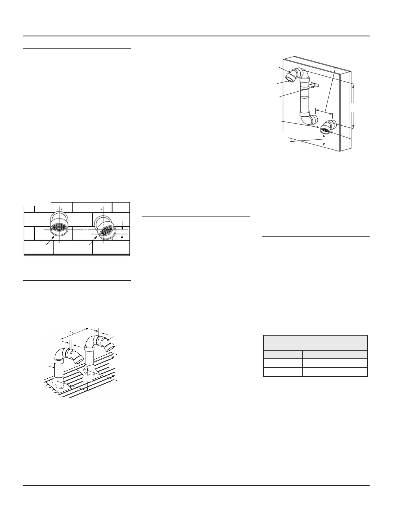
SIDE WALL VENT TERMINATION (STANDARD)
Important: When terminang the vent
on a side wall, the following
specicaons pertaining to
terminal locaon must be
followed. See Figure 29.
1. The air intake terminal and the exhaust
vent terminal must terminate on the
same exterior wall.
2. The vercal center-line of the air intake
terminal must be located at a minimum
of 8” from the vercal center-line of the
exhaust vent terminal.
3. The horizontal center-line of the air intake
terminal may not be located more than
24” below the horizontal center-line of
the exhaust vent terminal.
4. To avoid exhaust recirculaon, the air
intake terminal may be rotated away from
the exhaust vent terminal. See Figure 29.
SIDE WALL
MIN 8”
(20 CM)
EXHAUST
VENT
TERMINAL
INTAKE
VENT
TERMINAL
24“ MAX
(61 CM)
Figure 29. Sidewall Vent Clearances*
Roof Vent Termination (Standard)
Important: When terminang the vents
through a roof, the following
specicaons pertaining to
terminal locaon must be
followed. See Figure 30.
8 inches min.
(20 cm)
A & B; ABOVE
ANTICIPATED SNOW LEVEL
OR
18 inches (45 cm)
MIN. ABOVE ROOF
EXHAUST
VENT
TERMINAL
INTAKE
VENT
TERMINAL
1 inch
(2.5 cm)
A
B
1 inch
(2.5 cm)
Figure 30. Roof Vent Snow Clearances
1. The air intake terminaon and the
exhaust vent terminaon shall extend
12” above ancipated snow level and at
least 12” above the roof.
2. Must provide proper support for all
pipes protruding through roof.
3. The vercal roof terminaons should
be sealed with a plumbing roof boot or
equivalent ashing.
4. The air intake terminaon and the
exhaust vent terminaon must penetrate
the same side of roof.
5. The center-line of the air intake
terminaon and the center-line of the
exhaust vent terminaon must not be
closer than 8”.
6. The air intake terminal and the exhaust
vent terminal must be oriented facing
downward and the same direcon.
SIDE WALL VENT FOR COLD CLIMATES
Some winter weather condions present a risk
of ice accumulaon at the intake terminaon
screen. Such accumulaon will restrict intake
air ow. If local condions present this risk, the
terminaon conguraon shown in Figure 31 is
recommended. This will reduce the possibility
of exhaust gas recirculaon as well as reduce
the chance of ice accumulaon.
If necessary to avoid snow accumulation,
the intake vent terminal may be ed with
a riser similar to that on the exhaust vent
terminal. Both the intake and exhaust vent
terminaons may be 90° elbows if specied by
local requirements.
Note: The vercal center-line of the air intake
terminaon and the vercal center-line
of the exhaust vent terminaon must
not be closer than 8”.
Important: Elbows (excluding the
terminaon elbow) and risers
must be considered when
calculang total equivalent
vent length. See Table 6 (page
23).
WALL
MOUNTED
SUPPORT
BRACKET
8 inches MIN.
(20 cm)
INTAKE
TERMINAL
EXHAUST
TERMINAL
VENT
SCREEN
INSIDE
VENT
SCREEN
24 inches MAX.
(61 cm)
12 inches (30 cm)
ABOVE GRADE
OR ABOVE
ANTICIPATED
SNOW LEVEL
Figure 31. Sidewall Vent Termination Snow Clearances
Debris screens may be removed while there
is a risk of ice accumulaon but this can make
the air intake suscepble to debris buildup, the
entry of birds, other small animals or rodents. If
the debris screens are removed to prevent ice
accumulaon, it is recommended that they be
re-installed when the risk of ice accumulaon
has passed.
CONCENTRIC VENT TERMINATION
A concentric vent terminaon kit (see Table
9) may be used for vertical or horizontal
terminaons. Figure 33 illustrates the concentric
vent kit for a horizontal (side wall) installaon.
To prevent rain water from entering the exhaust
outlet, slope the vent kit at a downward pitch
of 1/4” per 5’ away from the inside wall. Ensure
the combuson air intake locaon is above the
ancipated snow level. Figure 32 illustrates the
concentric vent terminaon kit in a vercal
(roof) installaon. Ensure the combuson air
intake locaon is above the ancipated snow
level.
Table 9. Concentric Vent Termination
Kits
Vent Dia. P/N
2” 100153586
3” 100111100
INSTALLING THE VENT SYSTEM
Residenal Condensing Gas Water Heaters • 27
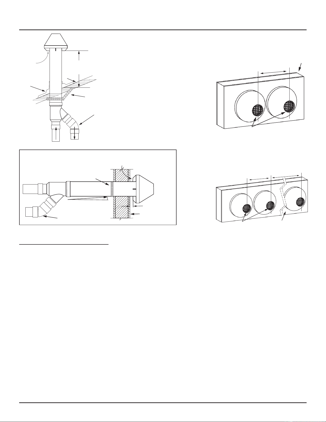
Combustion
Air
Above Anticipated Snow
Level or 18” (450 mm)
Minimum Above the Roof
Roof
Strapping
(field-supplied)
Elbow
(field-supplied)
Combustion Air
Exhaust
Flashing
(field-supplied)
Figure 32. Concentric Termination (Vertical)
ORIENTATION OF EXHAUST PIPING AND COMBUSTION
AIR PIPING RELATIVE TO EACH OTHER MAY BE HORI
-
ZONTAL (AS SHOWN) OR AT ANY OTHER ANGLE TO SUIT
THE INSTALLATION.
Combustion
Air
Strapping
(field-supplied)
Elbow
(field-supplied)
Slope: 4 % grade
Wall
1” (25 mm) Minimum
Figure 33. Concentric Terminaon (Horizontal)
MULTIPLE CONCENTRIC VENT TERMINATION
When two concentric vent kits are being
installed, the vent hood centers shall be either
less than 9.5” apart or more than 43.5” apart.
Spacings between 9.5” and 43.5” are not
allowed due to the possibility of exhaust cross
circulaon (see Figure 34).
When more than 2 kits are installed only 2 of
them shall be less than 9.5” apart. Never install
3 terminaon kits together less than 9.5” apart
(see Figure 35).
9.5 inches (24 cm ) maximum or
43.5 inches (1.1 m) minum
Wall
Vent
Screens
Figure 34. Through-Wall Multi-Concentric Vent
Termination
Note: If a terminaon elbow is required by
local codes, install vent screen in elbow
instead of the concentric vent exhaust.
9.5 inches (24 cm) maximum
Vent
Screens
43.5 inches (1.1 m) minimum
Wall
Figure 35. Three or More Sidewall Concentric Vent
Terminations
Note: If a terminaon elbow is required by
local codes, install vent screen in elbow
instead of the concentric vent exhaust.
INSTALLING THE VENT SYSTEM
28 • Residenal Condensing Gas Water Heaters
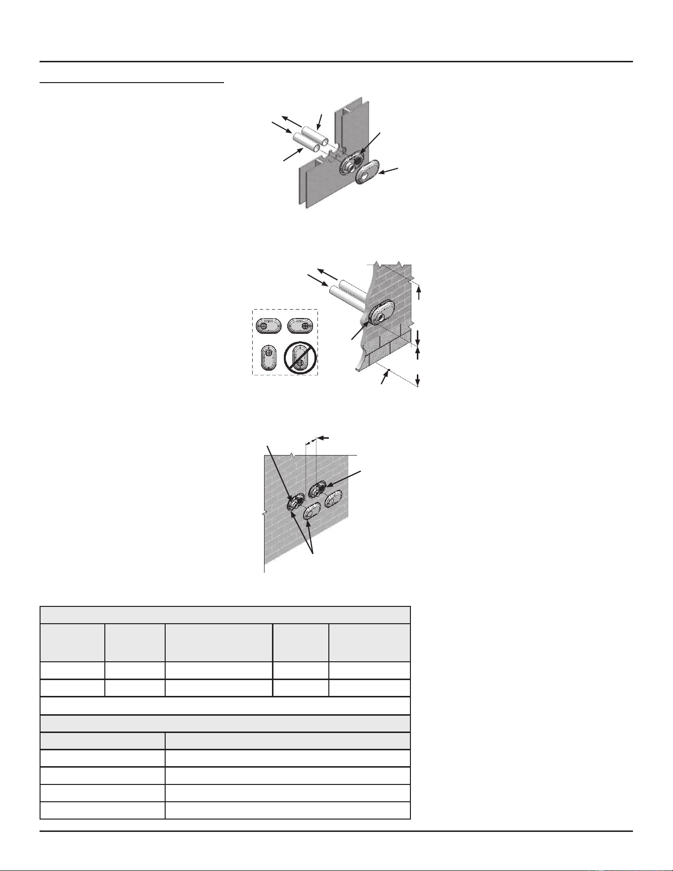
LOW PROFILE VENT INSTALLATION
This water heater is cered for sidewall direct
venting with IPEX System 636 Low Profile
Vent Kit. Follow instrucons below for proper
installaons.
All termination kits must be located and
installed in accordance with local building
code and CSA B149.1 Natural Gas and Propane
Installation Code.
1. Once the proper locaon has been
determined, cut 2 holes in the wall large
enough to accommodate the pipe. Pipe
diameters and distance between hole
centers can be found in Table 10 (page
29).
2. Slide both the intake and exhaust pipes
through the holes. Solvent cement both
pipes to the base of the vent terminaon
kit, follow the solvent cemenng
procedures outlined in the IPEX System
636 Installation Guide, which is available
on the web www.ipexinc.com.
3. To fasten the Base to the wall, use the
supplied screws and anchors. A 3/16”
(5 mm) hole, 1-3/16” (30 mm) deep,
will need to be drilled for the anchors.
Locate the anchor hole using the base as
a template.
4. Screw the Cap to the Base using the
supplied screws.
5. Once the vent terminaon and pipes are
secured, the wall penetraons will need
to be sealed from the interior using a
PVC-compable sealant material.
6. All vent pipes and air inlets must
terminate at the same height to avoid
possibility of severe personal injury,
death, or substanal property damage.
7. Operate heater through 1 heat cycle to
ensure combuson-air and vent pipes are
properly connected to concentric vent
terminaon
Vent Base
Vent Cap
Air Inlet
Piping
Vent (Exhaust)
Piping
Figure 36. Inlet and Vent Flow in Low Profile Installation
To Heater Intake
Air Connection
From Heater Vent
Pipe Connection
Vent/Air
Termination
12”
Min to
Over-
Hang
12”
Min
Grade or
Snow Line
Possible Orientations
Figure 37. Low Profile Sidewall Clearances
12” Min between Edge of Air Inlet
and Adjacent Vent
(Exhaust) Outlet
Air Inlet
Vent/Air
Termination
Vent (Exhaust)
Figure 38. Multiple Low Profile Vent Clearances
Table 10. Low Prole Termination Kits - Dimensions
AOS Kit
Number
IPEX
Part Num-
ber Description
Pipe
Outside
Diameter
Hole Spacing
(Center to
Center)
100086241 196984 2” Flush Mount Vent Ki 2.375” 5.63”
100187887 196985 3″ Flush Mount Vent Kit 3.5″ 7.63"
Each Kit Contains
Qty Item Description
1 Base (two holes)
1 Cap (one hole)
8 Stainless Steel Screws
4 Plasc Anchors
INSTALLING THE VENT SYSTEM
Residenal Condensing Gas Water Heaters • 29
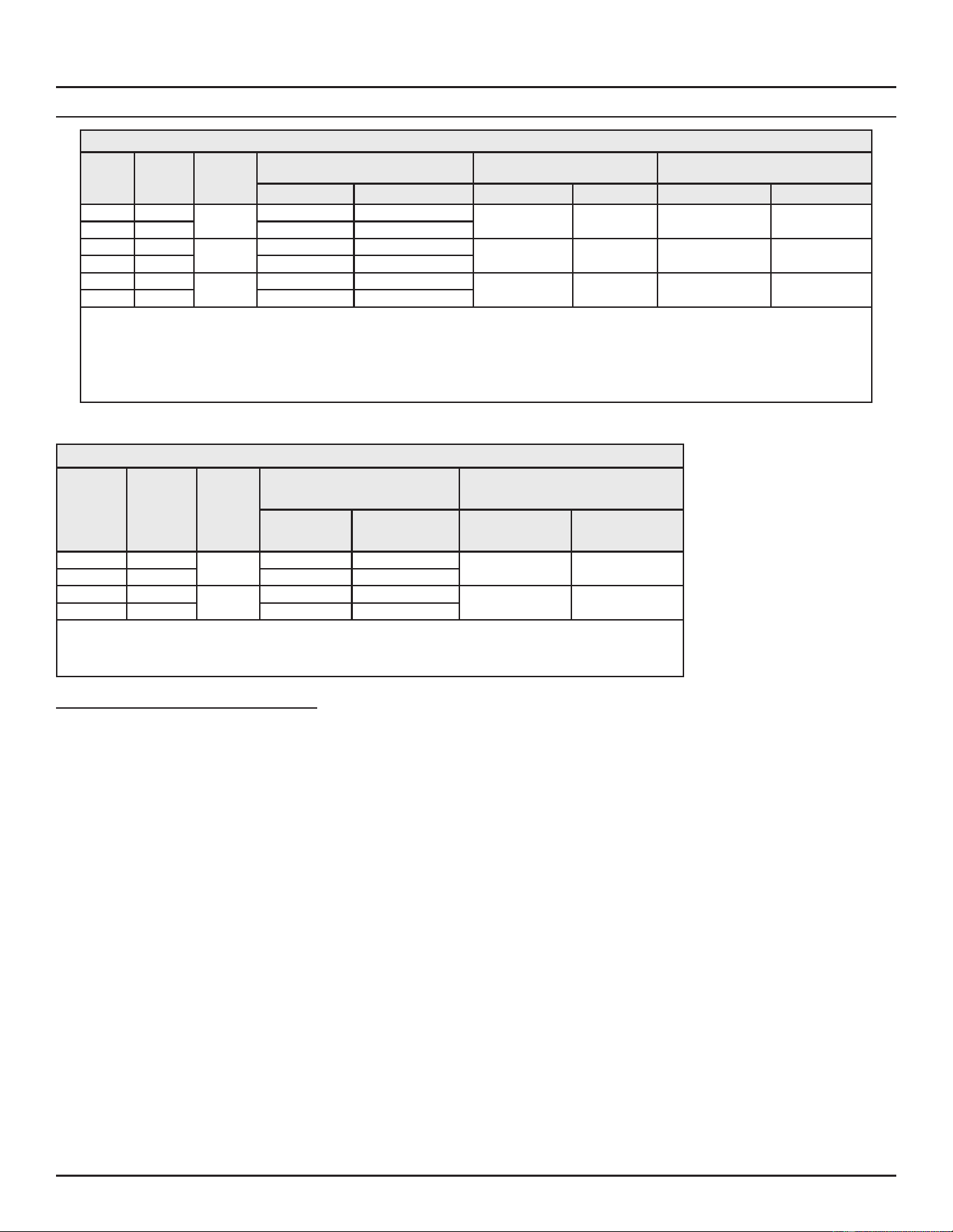
CALCULATING EQUIVALENT FEET (PDV)
Table 11. Calculating Equivalent Feet (PDV)
Water
Heater
Model
Heater
Input
(Btu/Hr)
Vent Size
(Inside
Diam.)
Pressure Switch Settings (in. w.c.) 2 Pipe Equiv. Vent Length Conc. Vent Equiv. Vent Length
Intake (Nat/LP) Exhaust (Nat/LP) Max. Min. Max. Min.
40 gal. 50,000
2”
-1.88/-1.62 1.8/1.43
60 . (18.3 m) +
terminaon
7 . (2.1 m) +
terminaon
50 . (15.2 m) +
terminaon
7 . (2.1 m) +
terminaon
50 gal. 65,000 -1.88/-1.62 1.8/1.43
40 gal. 50,000
3”
-1.88/-1.62 1.8/1.43
150 . (45.7 m) +
terminaon
10 . (3.0 m) +
terminaon
150 . (45.7 m) +
terminaon
10 . (3.0 m) +
terminaon
50 gal. 65,000 -1.88/-1.62 1.8/1.43
40 gal. 50,000
4”
-1.88/-1.62 1.8/1.43
180 . (54.8 m) +
terminaon
15 . (4.6 m) +
terminaon
N/A N/A
50 gal. 65,000 -1.88/-1.62 1.8/1.43
Notes:
1. A horizontal vent must have a 45° or 90° vent terminaon elbow to direct the vent pipe downward unless otherwise specied by local requirements.
2. A vercal vent must have a 90° elbow to direct the vent pipe horizontally followed by a vent terminaon 45° elbow to direct the vent pipe downward unless otherwise
specied by local requirements.
3. If addional elbows are used in the vent system the allowable vent lengths are reduced.
4. Two 45° elbows are considered the equivalent of one 90° elbow.
Table 12. Calculating Low Prole Equivalent Vent Length
Water
Heater
Model
Heater
Input (Btu/
Hr)
Vent Size
(Inside
Diam.)
Pressure Switch Settings (in.
w.c.) Low Prole Equiv. Vent Length
Intake (Nat/LP) Exhaust (Nat/LP) Max. Min.
40 gal. 50,000
2”
-1.88/-1.62 1.8/1.43
60 . (18.3 m) +
terminaon
7 . (2.1 m) + termi-
naon
50 gal. 65,000 -1.88/-1.62 1.8/1.43
40 gal. 50,000
3”
-1.88/-1.62 1.8/1.43
150 . (45.7 m) +
terminaon
10 . (3.0 m) +
terminaon
50 gal. 65,000 -1.88/-1.62 1.8/1.43
Notes:
1. If addional elbows are used in the vent system the allowable vent lengths are reduced.
2. Two 45° elbows are considered the equivalent of one 90° elbow.
INSTALLING THE VENT SYSTEM
30 • Residenal Condensing Gas Water Heaters
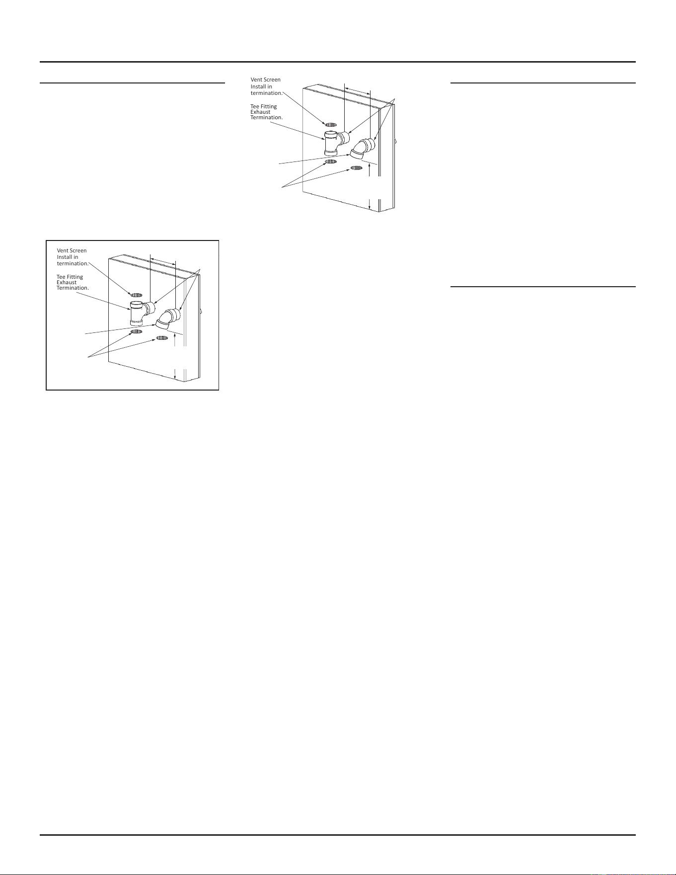
INSTALLING A NEW TEE TERMINATION
A tee fitting, purchased separately, as the
exhaust terminaon and a 45° elbow as the air
intake terminaon are permied on the water
heater models covered by this manual. The
tee terminaon is approved for 2” and 3” vent
diameters only.
Note: The sound suppressor must not be
installed if the tee terminal is installed.
When a Tee terminaon is used, properly sized
vent debris screens must be installed as seen in
Figure 25 (page 24).
Vent Screen
Install in
termination.
Tee Fitting
Exhaust
Termination.
45° Elbow
Air Intake
Termination
Vent Screen
Install in
termination.
*Or above anticipated snow level.
18”
(457 mm)
min
Apply sealant
to both sides
of wall.
12”
(300 mm)
min*
Figure 39. Tee Fitting Exhaust Termination with 90 Intake
Termination
Vent Screen
Install in
termination.
Tee Fitting
Exhaust
Termination.
45° Elbow
Air Intake
Termination
Vent Screen
Install in
termination.
*Or above anticipated snow level.
18”
(457 mm)
min
Apply sealant
to both sides
of wall.
12”
(300 mm)
min*
Figure 40. Raised Tee Fitting Exhaust Termination with 90
Intake Termination
INSTALLING A NEW 90° TERMINATION
A 90° elbow, purchased separately, as the
exhaust terminaon and a 45° elbow as the air
intake terminaon are permied on the water
heater models covered by this manual. The
90° terminaon is approved for 2” and 3” vent
diameters only.
Note: The sound suppressor must not be
installed if the 90° terminal is installed.
When a 90° terminaon is used, properly sized
vent debris screens must be installed as seen in
Figure 25 (page 24).
POWER VENT (PV)
It is imperave that the rst hanger (or support)
be located on the horizontal run immediately
adjacent to the rst 90° elbow from the vercal
rise. Support method used should isolate
the vent pipe from the oor joists or other
structural members to prevent the transmission
of noise and vibraon. Do not support, pin, or
otherwise secure the venng system in a way
that restricts the normal thermal expansion
and contracon of the chosen venng material.
If the water heater is being installed as a
replacement for an existing power vented
heater in pre-existing venting, a thorough
inspection of existing venting system must
be performed prior to any installaon work.
Verify that correct material, as detailed in this
manual, has been used, and that the minimum
or maximum vent lengths and terminal locaon
as detailed in this manual have been met.
INSTALLING THE VENT SYSTEM
Residenal Condensing Gas Water Heaters • 31
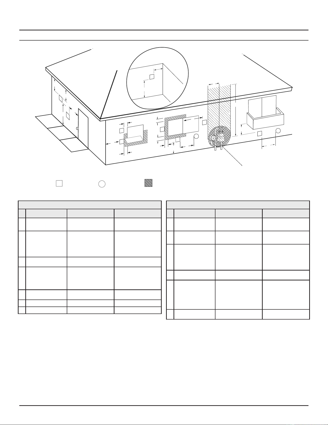
TERMINATION CLEARANCES OTHER THAN SIDEWALL DIRECT VENT
Fixed
Closed
Operable
Fixed
closed
Operable
B
V
V
V
V
V
V
V
V
C
B
B
X
A
M
K
Regulator vent outlet
In the event no
regulator is present,
H and I can be
disregarded
.
V
Legend:
= Vent terminal
X
= Air supply inlet
= Area where terminal is not permitted
B
B
J
F
X
B
L
E
D
Inside
corner detail
V
A
G
H
15 ft
I
Figure 41. Other than Direct Vent Using Outside Air
Table 13. Termination Clearances for Sidewall Direct Vent
Type of Clearance Canadian Installations 1 US Installations 2
A
Clearance above grade,
veranda, porch, deck or
balcony
12 inches (30 cm) 12 inches (30 cm)
B
Clearance to window or
door that may be opened
• 6 in (15 cm) for appliances ≤
10,000 Btuh (3 kW)
• 12 in (30 cm) for appliances
> 10,000 Btuh (3 kW) and ≤
100,000 Btuh (30 kW),
• 36 in (91 cm) for appliances >
100,000 Btuh (30 kW)
4 feet (1.2 m) below or to side
of opening;
1 foot (30 cm) above opening
C
Clearance to permanently
closed window
6 inches (15 cm)* 6 inches (15 cm)*
D
Vercal clearance to
venlated sot located
above the terminal within a
horizontal distance of 2 feet
(61 cm) from the center line
of the terminal
12 inches (30 cm) 12 inches (30 cm)
E
Clearance to unvenlated
sot
12 inches (30 cm) 12 inches (30 cm)
F
Clearance to outside corner 2 feet (60 cm)* 2 feet (60 cm)*
G
Clearance to inside corner 18 inches (45 cm)* 18 inches (45 cm)*
Table 13. Termination Clearances for Sidewall Direct Vent
Type of Clearance Canadian Installations 1 US Installations 2
H
Clearance to each side of
center line extended above
meter/regulator assembly
3 (91 cm) within a height 15
(4.6 m)
Clearance in accordance with
local installaon codes and the
requirements of the gas supplier
I
Clearance to service regula-
tor vent outlet
3 (1.83 m) Clearance in accordance with
local installaon codes and the
requirements of the gas supplier
J
Clearance to a non me-
chanical air supply inlet into
building or combuson air
inlet to any other appliance
• 6 in (15 cm) for appliances ≤
10,000 Btuh (3 kW)
• 12 in (30 cm) for appliances
> 10,000 Btuh (3 kW) and ≤
100,000 Btuh (30 kW)
• 36 in (91 cm) for appliances
>100,000 Btuh (30 kW)
4 feet (1.2 m) below or to side
of opening;
1 foot (30 cm) above opening
K
Clearance to a mechanical
air supply inlet
6 feet (1.83 m) 3 feet (91 cm) above if within 10
feet (3 m) horizontally
L
Clearance above paved
sidewalk or paved driveway
located on public property
7 feet (2.13 m)† 7 (2.13 m) for mechanical dra
systems (Category I appliances);
vents for Category II and IV
appliances cannot be located
above public walkways or other
areas where condensate or
vapor can cause a nuisance or
hazard
M
Clearance under veranda,
porch, deck, or balcony
12 inches (30 cm) ‡ 12 inches (30 cm) ‡
1 In accordance with the current CSA B149.1, Natural Gas and Propane Installation Code.
2 In accordance with the current ANSI Z223.1/NFPA 54, National Fuel Gas Code.
† A vent shall not terminate directly above a sidewalk or paved driveway that is located between two single family dwellings and serves both dwellings where it may cause hazardous frost or
ice accumulaons on adjacent property surfaces.
‡ Permied only if veranda, porch, deck, or balcony is fully open on a minimum of two sides beneath the oor.
INSTALLING THE VENT SYSTEM
32 • Residenal Condensing Gas Water Heaters
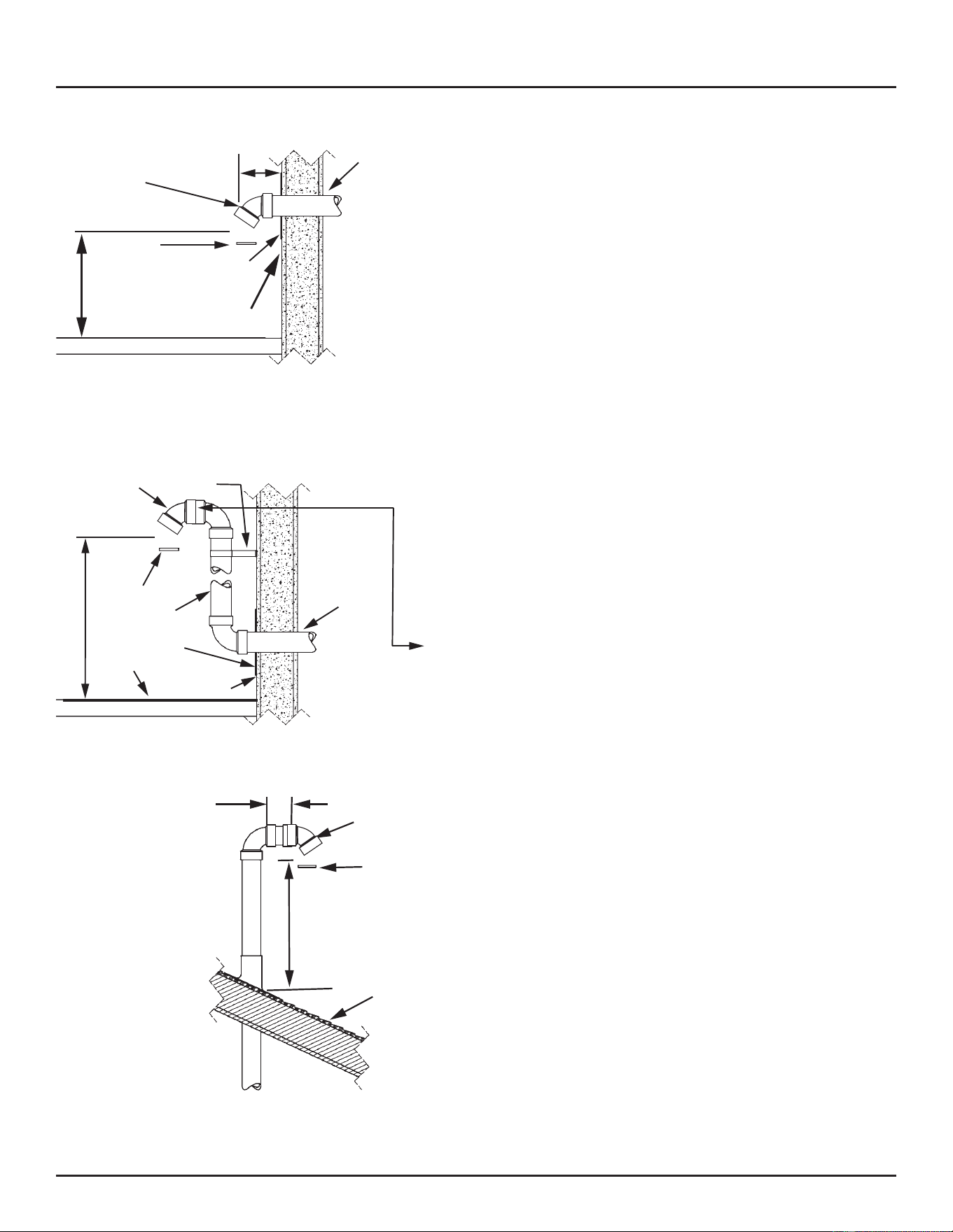
Attach
termination
elbow.
Debris
Screen
(Install into
Elbow)
12”
(300 mm)
min.*
Ground
Level*
Cover Plate
(optional)
Sealant
(under plate)
Vent Pipe to be
sloped (down) toward
heater to prevent
water from collecting.
May require a
condensate tee.
Sealant
6”
(150 mm)
*Where snow cover is normal during winter,
ensure outlet is installed above the anticipated
snow level.
Figure 42. Side-Wall Vent Terminaon - Normal Snow Cover
Attach
termination
elbow.
Bracket
Debris
Screen
(Install into
Elbow)
12”
(300 mm)
min.*
Ground
Level*
Cover Plate
(optional)
Sealant
(under plate)
Vent Riser
Sealant
Equivalent Vent
Length
Measured from
this Position
Vent Pipe to be
sloped (down) toward
heater to prevent
water from collecting.
May require a
condensate tee.
*Where snow cover is above normal during
winter, ensure outlet is installed above the
anticipated snow level.
Figure 43. Side-Wall Vent Terminaon - Above Normal Snow Cover
A vent used in a special
venting system with positive
vent pressure and passing
through a roof shall extend
at least 18” (45 cm ) above
the highest point where it
passes through the roof
surface and any other
obstruction witin a horizontal
distance of 18” (45 cm ) . A
vertical venting system must
be supported every 5 feet
(1.5 m).
Roof Line
18” (45 cm ) or
above anticipated
snow level.
Debris Screen
(Install into
elbow.)
Attach
termination
elbow.
3”
(7.5 cm) min.
Figure 44. Roof Vent Terminaon
INSTALLING THE VENT SYSTEM
Residenal Condensing Gas Water Heaters • 33
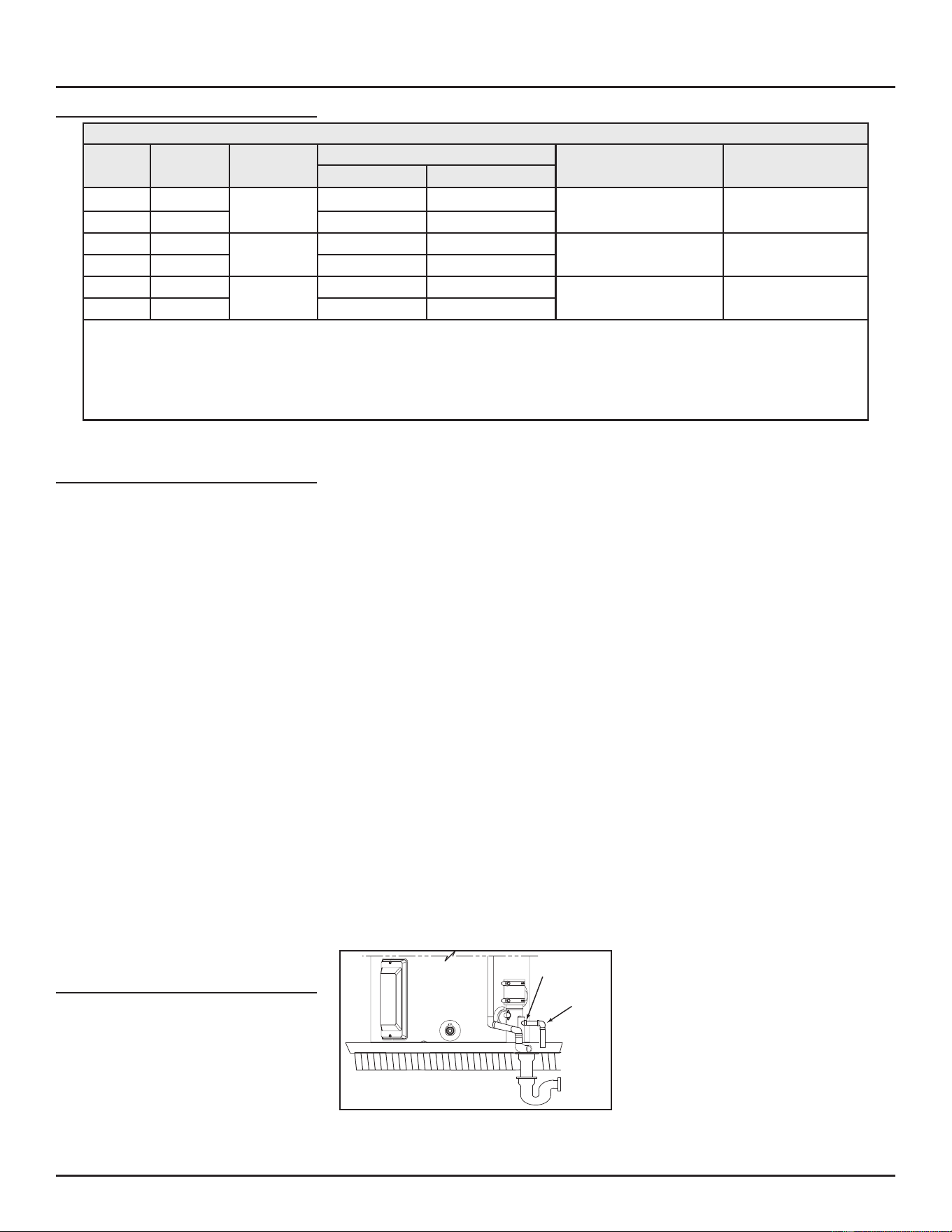
CALCULATING EQUIVALENT FEET (PV)
Table 14. Calculating Equivalent Feet (PV)
Water
Heater
Model
Heater Input
(Btu/Hr)
Vent Size
(Inside Diam.)
Pressure Switch Settings (in. w.c.)
Max. Equivalent Vent
Length
Min. Equivalent Vent
LengthIntake (Nat/LP) Exhaust (Nat/LP)
40 gal. 50,000
2”
-1.88/-1.62 1.8/1.43
60 . (18.3 m) + terminaon 7 . (2.1 m) + terminaon
50 gal. 65,000 -1.88/-1.62 1.8/1.43
40 gal. 50,000
3”
-1.88/-1.62 1.8/1.43
150 . (45.7 m) + terminaon
10 . (3.0 m) + termina-
on
50 gal. 65,000 -1.88/-1.62 1.8/1.43
40 gal. 50,000
4”
-1.88/-1.62 1.8/1.43
180 . (54.8 m) + terminaon
15 . (4.6 m) + termina-
on
50 gal. 65,000 -1.88/-1.62 1.8/1.43
Notes:
1. All vent pipe material must be schedule 40.
2. Snorkel terminaon elbows' equivalent lengths must be deducted from total vent length.
3. Concentric vent terminaons are not available for PV installaons.
4. Use long radius elbows where possible. Minimum distance between 90º elbows should be 6” (150 mm) wherever possible.
5. Venng systems may use a maximum of ve (5) 90° elbows.
6. Use proper screen terminaon.
VENT INSTALLATION
1. Carefully inspect the enre venng
system for any signs of cracks or fractures,
parcularly at joints between elbows and
other ngs and straight runs of vent
pipe.
2. Check system for signs of sagging or
other stresses in joints as a result of
misalignment of any components in
the system. If any of these condions
are found, they must be corrected in
accordance with the venng instrucons
elsewhere in this manual before
compleng installaon and pung the
water heater into service.
3. The vent piping shall be connected to the
condensate trap with a rubber coupling
and secured with gear clamps. The
condensate trap, pressure switch, so
tubing, coupling, and clamps are provided
with the heater in the vent kit. The so
tubing is used to connect the condensate
trap to the outlet air pressure switch.
Ensure that the tubing is connected from
the condensate trap to the outlet air
pressure switch aluminum tubing located
next to the condensate trap. See Figure 26
(page 25).
CONDENSATE (EXHAUST)
This appliance is a condensing unit and will
have condensate build up throughout the
exhaust venng system. The vent pipe should
be sloped upwards (1/4” per foot) away from
the water heater. Adequate means for draining
back to the condensate trap and disposing
of the condensate must be made by the
installer. Condensaon in the venng system
is dependent upon installation conditions
including, but not limited to:
• ambient temperature and humidity of
installaon locaon,
• ambient temperature and humidity of
venng space,
• vent discharge and slope,
• product usage.
Note: Do not use the condensaon trap as a
support point. It not designed to carry
the load or stresses of the venting
system. Vent piping must be supported
adequately and not put any weight on
the condensaon trap.
Connect a suitable condensate drain line to
the port on the condensate trap using a 1/2”
FNPT connector. The condensate line must
be horizontal or inclined towards the drain.
Ensure the drain line terminates at a drain as
condensate will ow from the end. Ensure that
any discharge will exit the condensate drain
line near a suitable building drain, or external
to the building.
Note: In cold climates it is recommended the
condensate drain be terminated at a
suitable drain inside the building.
BUILDING
DRAIN
CONDENSATE
DRAIN LINE -
FIELD SUPPLIED
CONDENSATE
DRAIN LINE
CONNECTION
Figure 45. Condensate Drain Piped to Floor Drain
Caution must be used to ensure that drain
is free and clear of debris and will not allow
back-ow through the condensate drain line.
If the condensate does not drain properly it
will build up in the exhaust (vent) tee. This
will restrict the ow of ue gases and cause
the Blocked Exhaust pressure switch to open
its contacts. The control system monitors all
pressure switches, if the Blocked Exhaust Switch
contacts are open the control system will lock
out and disable heang operaon. The “Blocked
Exhaust” Fault code will be displayed on the
control system’s LCD.
Note: If the “Blocked Exhaust” Fault code is
ever displayed on the control system
LCD, check the condensate drain rst
and ensure it is not blocked.
DO NOT remove, modify or alter the factory
installed exhaust/condensate tee for any
reason. See Figure 45. The water heater’s vent
pipe is under a slight posive pressure while
unit is in operaon. The water trap inside of
the exhaust/condensate tee prevents ue gases
from escaping into the installed space.
INSTALLING THE VENT SYSTEM
34 • Residenal Condensing Gas Water Heaters
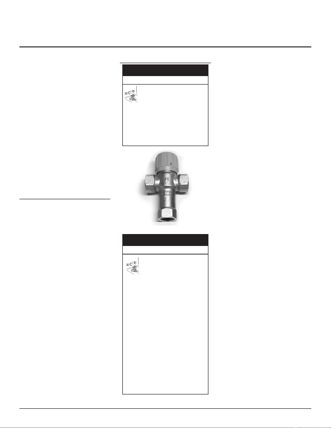
INSTALLING THE WATER HEATER
DO NOT install any external condensate trap.
The exhaust tee assembly has an internal
condensate trap built in.
• Care should be taken to ensure there is no
kink or twist in the condensate hose.
• Condensate hose must be free and clear
of debris and must not allow back ow
through drain line.
• Condensate must be able to ow freely to
an appropriate drain.
• Do not allow condensate hose to become
crimped closed.
• The condensate drain hose must not be
elevated above the connecon on the
condensate trap.
• Condensate from this water heater is
mildly acidic (pH levels between 4.3 and
5.0). Please note that some local codes
require that condensate be treated by
using a pH neutralizing lter prior to
disposal. Condensate neutralizer kits are
available. Contact your distributor or
Service Agency.
WATER LINE CONNECTIONS
To reduce the risk of unusually hot water
reaching the fixtures in the house, install
Thermostatic Mixing Valves at each point-
of-use.
The water piping installaon must conform
to these instructions and to all local and
national code authority having jurisdiction.
Good pracce requires that all heavy piping
be supported.
Read and observe all requirements in the
following secons before installaon of the
water piping begins:
1. Thermostatic Point-of-Use Mixing Valves.
2. Temperature-Pressure Relief Valve (page
37).
3. Closed Water Systems and Thermal
Expansion (page 36).
THERMOSTATIC POINT-OF-USE MIXING
VALVES
Improper installa�on of electrical
connec�ons can cause the water
heater to catch fire.
Do the following to avoid this hazard:
• Make electrical connections properly,
according to the instructions.
• Use 10 gauge solid copper wire.
• Use a UL listed or CSA approved strain
relief.
• Connect ground wire to green ground
screw.
Property Damage Hazard
⚠
CAUTION
Figure 46. Thermostatic Point of Use Mixing Valve
Water temperature over 125°F
(52°C) can cause severe burns
instantly resul�ng in severe injury
or death.
Observe the following precau�ons to avoid
this hazard:
• Children, the elderly, and the physically or
mentally disabled are at highest risk for scald
injury.
• Feel water before bathing or showering.
• Temperature limiting devices, such as
thermostatic point-of-use mixing valves must
be installed when required by codes and to
ensure safe temperatures at fixtures.
• The thermostat(s) on this water heater
has been factory set to approximately
120°F to reduce the risk of scalding. Higher
temperatures increase the risk of scalding,
but even at 120°F, hot water can scald. If you
choose a higher temperature, thermostatic
mixing valves, located at each point-of-use
are particularly important to help avoid
scalding.
• Thermostatic mixing valves located at each
point of use are particularly important to
avoid scalding.
Burn Hazard
⚠
DANGER
Water heated to a temperature which sases
space heang, clothes washing, dish washing,
and other sanizing needs can scald and cause
permanent injury upon contact. Short repeated
heang cycles caused by small hot-water uses
can cause a temperature increase of the hot
water above the heater’s temperature sengs.
In addion to using lowest possible temperature
seng that sases demand of applicaon, to
reduce the risk of scalding, install Thermostac
Mixing Valves (temperature liming valves) at
each point-of-use. See Figure 46 (page 35).
These valves automacally mix hot and cold
water to limit the temperature at the tap.
Thermostac Mixing Valves are available from
your local plumbing supplier. Consult a Qualied
Installer or Service Agency. Follow mixing valve
manufacturer’s instructions for installation
of the valves. Before changing the factory
seng on the control system, see Temperature
Regulation (page 47). If you choose a
higher temperature setting, Thermostatic
Mixing Valves located at each point-of-use are
parcularly important to help avoid scalding.
See Figure 46.
Some people are more likely to be permanently
injured by hot water than others. These
include the elderly, children, the inrm and
the physically/mentally disabled. Table 15
(published by U.S. Government Memorandum,
1978) shows the approximate time-to-burn
relaonship for normal adult skin. If anyone
using hot water provided by the water heater
being installed ts into one of these groups,
special precauons must be taken.
In all cases, the following burn table must be
used.
Residential Condensing Gas Water Heaters • 35
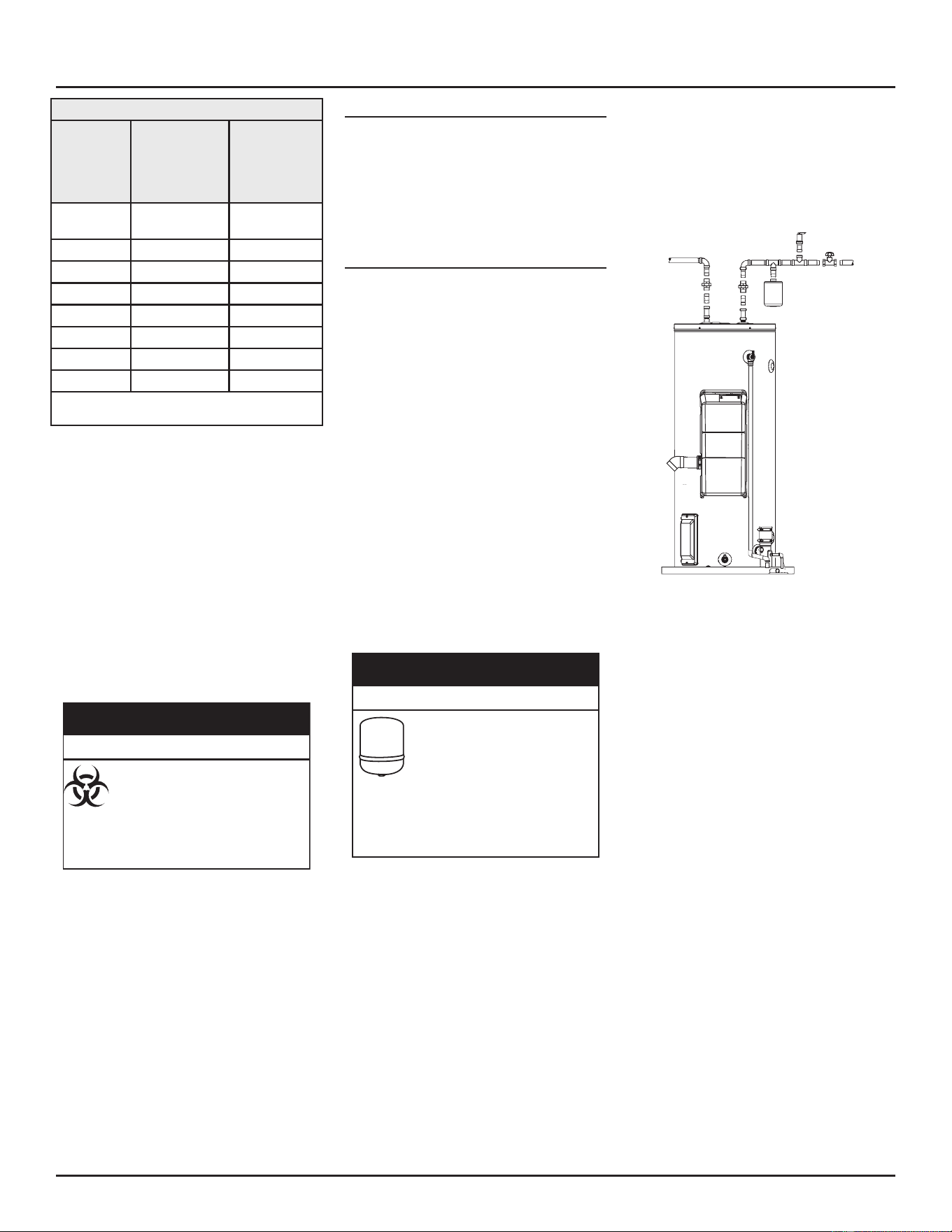
Table 15. Burn Time at Various Temperatures
Water
Temperature
°F (°C)
Time for 1st
Degree Burn
(Less Severe
Burns)
Time for Per-
manent Burns
2nd & 3rd
Degree
(Most Severe
Burns)
110 (43) (normal shower
temp.)
116 (47) (pain threshold)
116 (47) 35 minutes 45 minutes
122 (50) 1 minute 5 minutes
131 (55) 5 seconds 25 seconds
140 (60) 2 seconds 5 seconds
149 (65) 1 second 2 seconds
154 (68) instantaneous 1 second
(U.S. Government Memorandum, C.P.S.C., Peter L.
Armstrong, Sept. 15, 1978)
In addion to using lowest possible temperature
seng that sases demand of applicaon, to
reduce the risk of scalding, install Thermostac
Mixing Valves (temperature liming valves) at
each point-of-use. See Figure 45 (page 34).
These valves automacally mix hot and cold
water to limit the temperature at the tap.
Thermostac Mixing Valves are available from
your local plumbing supplier. Consult a Qualied
Installer or Service Agency. Follow mixing valve
manufacturer’s instructions for installation
of the valves. Before changing the factory
seng on the control system, see Temperature
Regulation (page 47).
Connec�ng the water heater to a
non-potable water system might
result in chemical or biological
contamina�on of the water heater.
Do not connect the water heater to a
non-potable water system.
Toxic Chemical Hazard
⚠
WARNING
CLOSED WATER SYSTEMS
Water supply systems may, because of code
requirements or such condions as high line
pressure, among others, have installed devices
such as pressure reducing valves, check valves,
and back ow preventers. Devices such as these
cause the water system to be a closed system.
THERMAL EXPANSION
As water is heated, it expands (thermal
expansion). In a closed system the volume
of water will grow when it is heated. As
the volume of water grows there will be a
corresponding increase in water pressure due
to thermal expansion. Thermal expansion can
cause premature tank failure (leakage). This
type of failure is not covered under the limited
warranty. Thermal expansion can also cause
intermient temperature-pressure relief valve
operaon: water discharged from the valve due
to excessive pressure build up. This condion
is not covered under the limited warranty.
The temperature-pressure relief valve is not
intended for the constant relief of thermal
expansion.
A properly sized thermal expansion tank should
be installed on all closed systems to control the
harmful eects of thermal expansion. Contact a
local plumbing service agency to have a thermal
expansion tank installed.
A water heater installed in a closed
water system can be damaged by
normal variations in pressure.
If the water heater is to be installed
in a closed water system, install a thermal
expansion tank or device to prevent pressure
changes from damaging the water heater.
Contact a qualified installer or service agency.
Property Damage Hazard
⚠
CAUTION
Do not apply heat to the cold water inlet.
Note: To protect against unmely corrosion of
hot and cold water ngs, it is strongly
recommended that dielectric unions
or couplings be installed on this water
heater (see Figure 47) when connected
to copper pipe.
Figure 47. Using Dielectric Unions or Couplings
Figure 47 also shows the typical aachment of
the water piping to the water heater. The water
heater is equipped with 3/4” NPT connecons
for all models.
INSTALLING THE WATER HEATER
36 • Residenal Condensing Gas Water Heaters
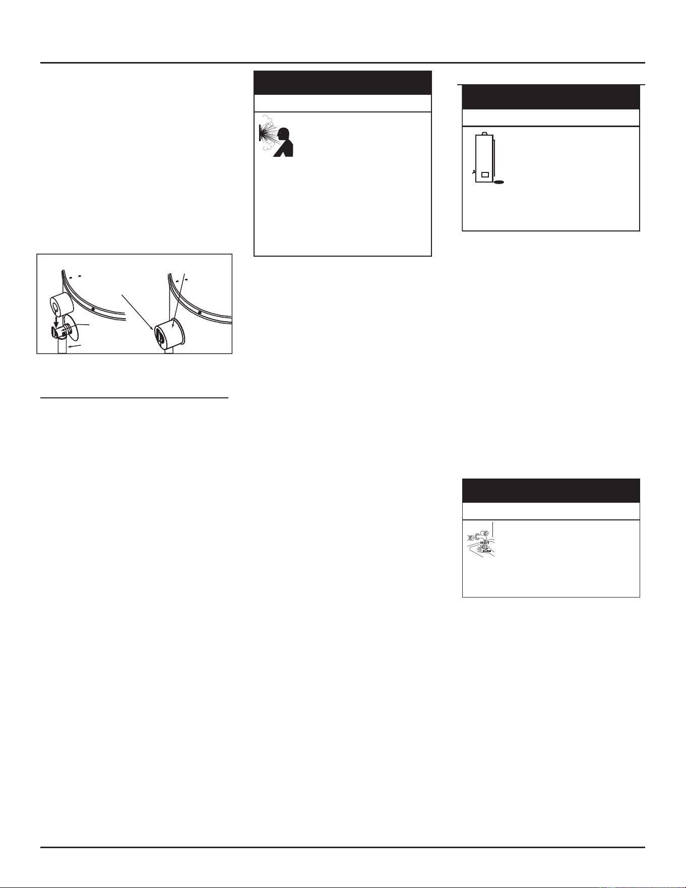
Note: If using copper tubing, solder tubing to
an adapter before aaching the adapter
to the water heater connecons. Do
not solder the water lines directly to
the water heater connecons. It will
damage the tank, T&P Valve and Pipe
Insulaon (if supplied).
Fit pipe insulaon over the incoming cold water
line and the hot water line. Make sure that the
insulaon is against the top cover of the heater.
Fit T&P valve insulaon over valve. Make sure
that the insulaon does not interfere with the
lever of the T&P valve. Secure all insulaon
using tape.
T&P Relief Valve
T&P Relief Valve
Drain Line
Manual Relief Lever
T&P Relief Valve Insulation
(Outlet opening on underside)
Figure 48. Installing Insulation Over T&P Valve
TEMPERATURE-PRESSURE RELIEF VALVE
This water heater is provided with a properly
rated/sized and certified combination
Temperature-Pressure Relief Valve (T&P
relief valve) by the manufacturer. The valve
is cered by a naonally recognized tesng
laboratory that maintains periodic inspecon
of producon of listed equipment of materials
as meeng the requirements for Relief Valves
for Hot Water Supply Systems, ANSI Z21.22 •
CSA 4.4, and the code requirements of ASME.
If replaced, the new T&P valve must meet the
requirements of local codes, but not less than
a combination Temperature-Pressure Relief
Valve rated/sized and cered as indicated in
the previous paragraph. The new valve must
be marked with a maximum set pressure not
to exceed the marked hydrostatic working
pressure of the water heater (150 psi / 1,035
kPa) and a discharge capacity not less than the
water heater Btu/hr or kW input rate as shown
on the water heater’s model rang plate.
Note: In addition to the factory installed
Temperature-Pressure Relief Valve on
the water heater, each remote storage
tank that may be installed and piped
to a water heang appliance must also
have its own properly sized, rated and
approved Temperature-Pressure Relief
Valve installed.
High temperature or pressure in
the water heater can cause the
water heater to explode resul�ng
in severe injury or death.
• A properly sized temperature-pressure
relief valve must be installed in the opening
provided.
• The temperature-pressure relief valve must
comply with
ANSI Z21.22-CSA4.4
and
ASME
code.
• Do not plug, block, or cap the discharge
line.
Property Damage Hazard
⚠
CAUTION
For safe operaon of the water heater, the
Temperature-Pressure Relief Valve must not
be removed from its designated opening nor
plugged. The Temperature-Pressure Relief Valve
must be installed directly into the ng of the
water heater designed for the Temperature-
Pressure Relief Valve. Install discharge piping so
that any discharge will exit the pipe 6” above an
adequate oor drain, or external to the building.
In cold climates it is recommended that it be
terminated at an adequate drain inside the
building. Be certain that no contact is made with
any live electrical part. The discharge opening
must not be blocked or reduced in size under
any circumstances.
Excessive length, over 30’ , or use of more than
four elbows can cause restricon and reduce
the discharge capacity of the valve.
No valve or other obstrucon is to be placed
between the Temperature-Pressure Relief
Valve and the tank. Do not connect discharge
piping directly to the drain. To prevent bodily
injury, hazard to life, or property damage,
the temperature-pressure relief valve must
be allowed to discharge water in adequate
quanes should circumstances demand. If
the discharge pipe is not connected to a drain
or other suitable means, the water ow may
cause property damage.
The purpose of a Temperature-Pressure Relief
Valve is to prevent excessive temperatures and
pressures in the storage tank. The T&P valve is
not intended for the constant relief of thermal
expansion. A properly sized thermal expansion
tank must be installed on all closed systems to
control thermal expansion. See Closed Water
Systems and Thermal Expansion (page 36).
T&P Valve Discharge Pipe
The temperature-pressure relief
valve can intermi�ently discharge
hot water throughout the normal
opera�on of the water heater,
which can cause water damage.
Locate the water heater so that the discharge
pipe terminates at an adequate and suitable
drain.
Property Damage Hazard
⚠
CAUTION
• Shall not be smaller in size than the
outlet pipe size of the valve, or have any
reducing couplings or other restricons.
• Shall not be plugged or blocked.
• Shall not be exposed to freezing
temperatures.
• Shall be of material listed for hot water
distribuon.
• Shall be installed so as to allow complete
drainage of both the Temperature-
Pressure Relief Valve and the discharge
pipe.
• Must terminate 6” above a oor drain
or other safe place. In cold climates, it is
recommended that the discharge pipe be
terminated at an adequate drain inside
the building.
• Shall not have any valve or other
obstrucon between the Temperature-
Pressure Relief Valve and the drain
The discharge from the
temperature-pressure relief valve
can be hot enough to burn.
Keep your hands clear of the
temperature-pressure relief valve discharge
outlet.
Burn Hazard
⚠
DANGER
INSTALLING THE WATER HEATER
Residenal Condensing Gas Water Heaters • 37
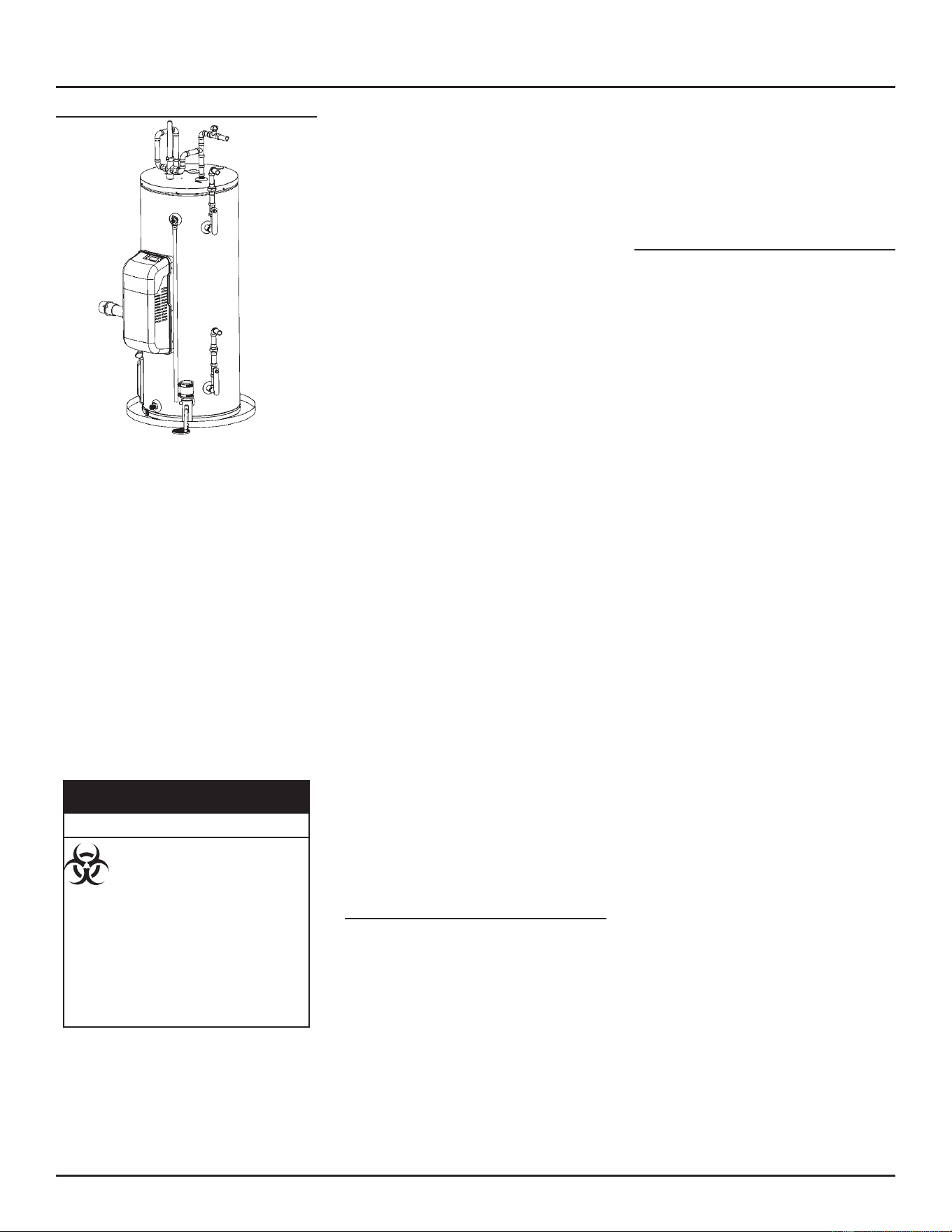
SPACE HEATING APPLICATIONS
Figure 49. Water Heater with Side Taps for Space Heating
This appliance has been design certified as
complying with American National Standards for
water heaters and is suitable for combinaon
water (potable) heang and space heang but
not space heang only applicaons.
Note: When there will be no domestic
hot water demand for an extended
period of me, the temperature set
point should be set at 90°F to prevent
“Stacking” and T&P discharge.
This heater is equipped with addional side
taps for use in space heating applications.
See Features and Components (page 13) for
locaons. If this water heater is to be used
to supply both space heating and potable
(drinking) water, the instrucons listed below
must be followed:
Use of chemical piping sealers or
connec�ng the water heater to a
non-potable water system might
result in chemical or biological
contamina�on of the water heater.
Do the following to avoid contamina�ng
the water heater:
• Do not connect the water heater to a
non-potable water system.
• Do not use piping that has been treated
with chromates, boiler seal, or other
chemicals.
Toxic Chemical Hazard
⚠
WARNING
Consult a Qualified Installer or Service
Agency. Follow manufacturer’s instructions
for installation of valves. Before changing
the factory seng on the control system, see
Temperature Regulation (page 47). Water
piping and vent piping occupy the space above
the water heater. Plan the water piping to
ensure it does not cause interference with the
vent piping. See Combustion Air and Ventilation
(page 21).
If this water heater is to be used to supply
both space heating and potable water, the
instrucons listed below must be followed:
• Be sure to follow the manual(s) shipped
with the air handler or other type heang
system.
• This water heater is not to be used as
a replacement for an exisng boiler
installaon.
• Do not use with piping that has been
treated with chromates, boiler seal or
other chemicals and do not add any
chemicals to the water heater piping.
• If the space heang system requires
water temperatures higher than required
for domesc water purposes, install a
Thermostac Mixing Valve in the domesc
(potable) hot water supply at each point-
of-use to limit the risk of scald injury. See
Figure 46 (page 35).
• Pumps, valves, piping and ngs must be
compable with potable water.
• A properly installed ow control valve is
required to prevent thermosiphoning.
Thermosiphoning is the result of a
connuous ow of water through the
air handler circuit during the o cycle.
Weeping (blow o) of the temperature-
pressure relief valve (T&P) or higher than
normal water temperatures are the rst
signs of thermosiphoning.
• The hot-water line from the water heater
should be vercal past any mixing valve
or supply line to the heang system to
remove air bubbles from the system.
• Do not connect the water heater to
any system or components previously
used with non-potable water heang
appliances when used to supply potable
water.
Combo Heating
This secon serves as a guide for the installaon
and use of “Combo” heang systems ulizing a
domesc water heater that has been specically
approved for such use. It is wrien for those
knowledgeable in the required trades and
professionals involved in the design and
installaon of Combo Heang Systems.
It is the responsibility of the installer/designer
to follow all applicable codes to ensure the
eecveness and safety of the installaon.
Your water heater is equipped with Combo
Heang capabilies and are shipped with the
two side plumbing taps PLUGGED (items 24 and
item 29 in Figure 3 (page 13)). See also Figure
49 (page 38). If the heater is to be operated
using the side taps for combo heang, these
plugs must be removed.
System Requirements
The following requirements must be met for the
installaon of Combo Heang Systems:
1. All components used for the distribuon
of water in the heang loop must be
suitable for potable water. These include
all piping, ngs, solder and uxes,
pumps for circulaon of water, valves,
etc.
2. The water heater must not be connected
to a hydronic heang system that has
been used previously. This heater is not
designed to be used in a space heang
only applicaon.
3. No boiler treatment chemicals of any
kind shall be introduced into the system.
4. The Combo System components must
be selected and sized to meet and
maintain the total calculated demands
for both domesc service hot water and
space heang requirement. The sizing
and installaon must be performed
in accordance with good engineering
pracce such as “ASHRAE Handbooks”,
HRAI’s Unied Combo Guidelines,
“Hydronics Instute Manuals”, ANSI
Z223.1, CSA F280, Naonal/Provincial
Building Codes, ANSI and/or codes
having jurisdicon.
5. The air handler (fan coil) and/or the
circulang pump in a baseboard
hydronic loop will require a dedicated
120 Vac circuit. This must be provided
and idened for this purpose.
6. All piping between the water heater and
the air handler or hydronic baseboard
loop must be adequately insulated to
reduce heat loss.
7. If the local jurisdicon requires a back-
ow preventer in the cold water line, an
expansion tank of adequate size must be
installed.
8.
INSTALLING THE WATER HEATER
38 • Residenal Condensing Gas Water Heaters
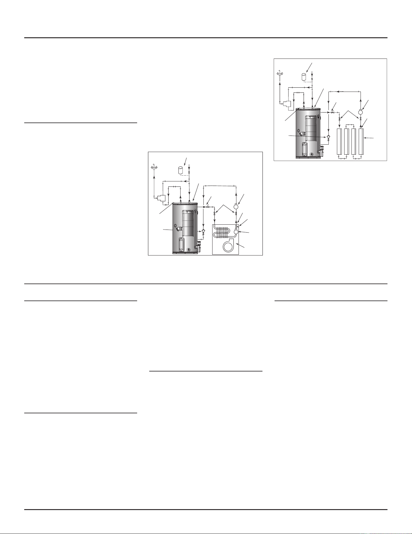
9. “Combo” Heang Systems require
higher water temperatures than
other applicaons. When the system
is used to supply water for Combo
Heang applicaons, a means, such
as Thermostac Mixing Valves at each
point-of-use, must be installed to temper
the water in order to reduce scald hazard
potenal. See Figure 50 and Figure 51.
Combo Heating Installation
The heang mode may be one of the following
opons:
A. A fan coil/air handler. See Figure 50 (page
39).
B. A hydronic baseboard (nned tube) loop/
In oor heang. See Figure 50 (page 39).
The following is a list of requirements for the
installaon of opon A or B.
1. Install shut-o valves and unions so that
the water heater can be isolated from
the heang module should servicing of
the water heater become necessary.
2. Install a drain valve at the lowest point
of the heang loop so that water can
be drained from the heang module
without aecng the water heater.
3. If the air handler does not have a venng
means at the highest point of the
piping arrangement, install an air bleed
at the highest point of the plumbing
arrangement.
Install a spring loaded check valve in the
space heang return line to prevent cold
water from continuously entering the
water heater. Failure to install such a valve
could cause “stacking” and cause the T&P
valve to open.
WATER
HEATER
HOT
OUTLET
EXPANSION TANK (OPTIONAL)
MIXING
VALVE
COLD
INLET
CHECK VALVE (IF USED
REQUIRES EXPANSION TANK)
COLD SUPPLY
HOSE BIB
(OPTIONAL)
FLOW
CONTROL
SUPPLY
RETURN
EXTERNAL
CIRCULATOR
AIR
HANDLER
HOT WATER
TO HOUSE
FIXTURE
C
H
M
INTERNAL
CIRCULATOR
DRAIN/
PURGE
VALVE
SPRING
LOADED
CHECK
VALVE
Figure 50. Typical Combo Heating Configuration
See also Massachusetts Installation Requirements
(page 12).
HOSE BIB
(OPTIONAL)
FLOW
CONTROL
SUPPLY
RETURN
EXTERNAL
CIRCULATOR
HYDRONIC
BASEBOARDS
(SERIES
CONNECTED
SHOWN)
HOT
OUTLET
EXPANSION TANK (OPTIONAL)
MIXING
VALVE
COLD
INLET
CHECK VALVE (IF USED
REQUIRES EXPANSION TANK)
COLD SUPPLY
HOT WATER
TO HOUSE
FIXTURE
C
H
M
SPRING
LOADED
CHECK
VALVE
Figure 51. Typical Combo Heating with Hydronic
Baseboards
ELECTRICAL INSTALLATION
Grounding Instructions
This water heater must be grounded in
accordance with the National Electrical Code
and/or local codes. These codes must be
followed in all cases. Failure to ground this
water heater properly may also cause errac
control system operaon.
This water heater must be connected to a
grounded metal, permanent wiring system; or
an equipment grounding conductor must be
run with the circuit conductors and connected
to the equipment grounding terminal or lead
on the water heater.
Electrical Supply
The water heaters covered in this manual
require a 120 Vac, 1Ø (single phase), 60 Hz, 10
amp power supply and must also be electrically
grounded in accordance with local codes or, in
the absence of local codes, with the National
Electrical Code, NFPA 70.
If any of the original wire as supplied with
the water heater must be replaced, it must
be replaced with 105°C rated wiring or its
equivalent, except in the burner housing. In this
case 200°C rated wire must be used.
Dedicated Power Wiring and Breakers
Dedicated power supply wires, ground wiring
and dedicated circuit breakers oen prevent
electrical line noise and should be considered
when installing the water heater.
Power Fluctuations and Electrical Noise
The water heater’s control system requires a
source of stable clean electricity for proper
operaon. Connecng the water heater to a
branch circuit that is subject to uctuaons
in voltage level or electrical line noise such as
EMI (electromagnec interference) or RFI (radio
frequency interference) may cause erratic
control system operaon and malfuncon.
A high quality power supply lter/suppressor
must be installed if the above condions exist.
Call the technical support phone number for
more informaon.
Note: Malfunctions caused by the power
supply and the costs to install the power
supply lters are not covered under the
limited warranty.
INSTALLING THE WATER HEATER
Residenal Condensing Gas Water Heaters • 39
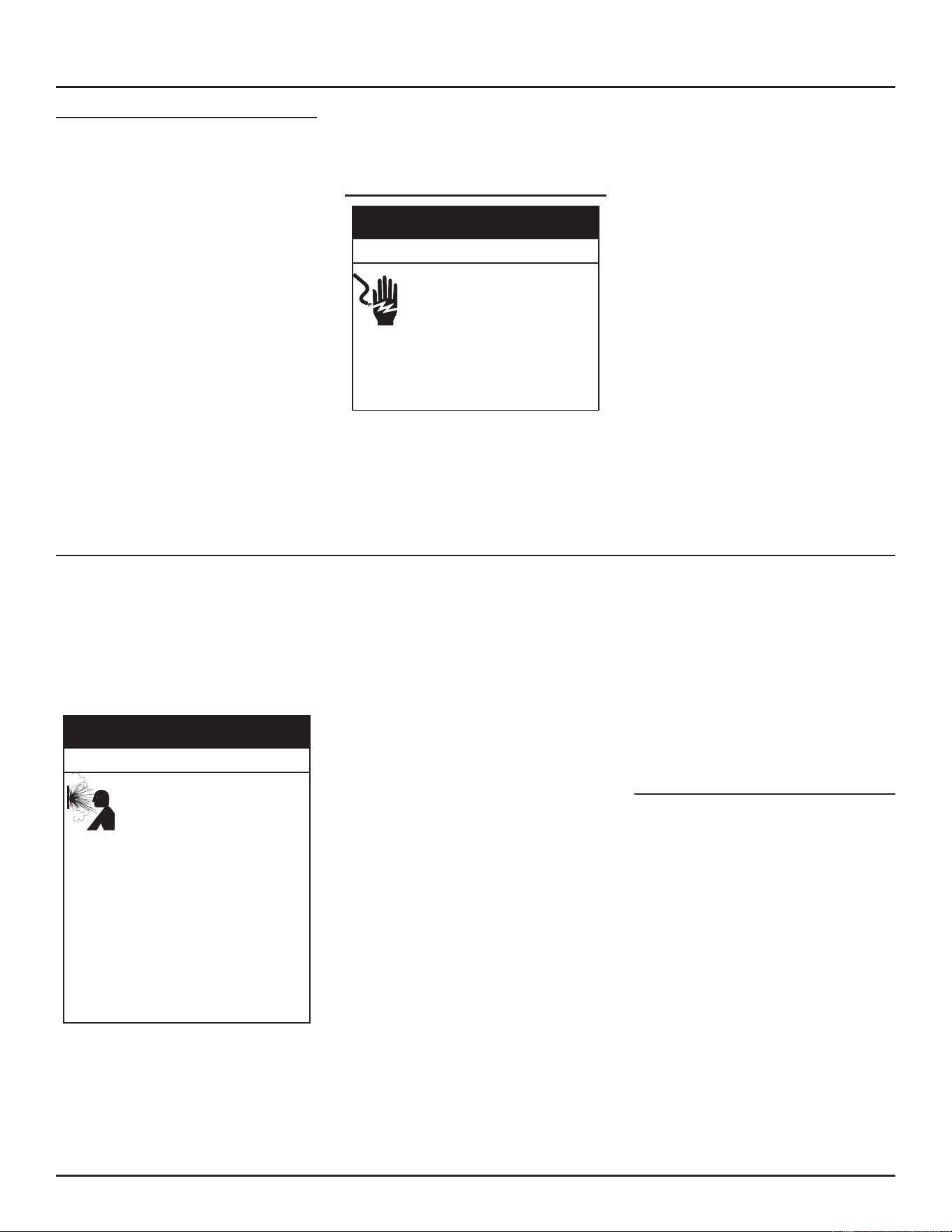
Electrical Wiring
If you lack the necessary skills required to
properly install the electrical wiring to this
water heater, do not proceed but have a
qualied electrician perform the installaon.
See Electrical Supply (page 39) for addional
requirements.
When making the electrical connecons, always
make sure:
• The voltage and frequency must
correspond to that specied on the water
heater data plate on the front of the
water heater.
• The electrical supply has the proper
overload fuse or breaker protecon. The
heater draws less than 10 amps.
• Wire sizes, connecons and conduits
comply with all applicable codes.
• The water heater and electrical supply are
properly grounded.
• This water heater must be “hard-wired”
do not use an extension cord to supply
electrical power to this water heater.
Note: The wiring diagram can be found in
Diagrams (page 58). Always reference
the wiring diagram(s) for the correct
electrical connecons.
Making the Electrical Connections
Servicing this water heater can
expose you to electrical current
capable of causing severe injury or
death.
• Disconnect power before servicing.
• Replace all parts and panels before
opera�ng.
• Failure to do so can result in e death or
electrical shock.
Electrical Shock Hazard
⚠
WARNING
Before plugging in the water heater, always
make sure:
• The voltage and frequency correspond to
that specied on the water heater wiring
diagram.
• The electrical outlet has the proper
overload fuse or breaker protecon.
1. The unit must be connected to a 120
VAC power supply. A dedicated circuit is
preferred. Do not use a GFI outlet.
2. The water heater must be properly
grounded.
3. This water heater is a polarity sensive
appliance and will not operate if the
power supply polarity is reversed.
Note: Note: Always reference the wiring
diagram for the correct electrical
connecons.
After making all electrical connections,
completely ll the tank with water and check
all connecons for leaks. Open the nearest
hot-water faucet and let it run for 3 minutes
to purge the water lines of air and sediment
and to ensure complete filling of the tank.
The electrical power may then be turned on.
Verify proper operaon aer servicing. See also
Installation Checklist (page 44).
GAS SUPPLY SYSTEM INSTALLATION
Low pressure building gas supply systems are
dened as those systems that cannot under any
circumstances exceed 14” w.c. (3.5 kPa). These
systems do not require pressure regulaon.
Measurements should be taken to insure
that gas pressures are stable and fall within
the requirements stated on the water heater
rang plate.
A�emp�ng to use the wrong type
of gas or excessive gas pressure
with the water heater might
cause it to explo de and catch fire,
resul�ng in property damage,
personal injury, or death.
Do the following to avoid this hazard:
• Use the type of gas specified for this water
heater on its rating label only.
• Use a pressure reducer valve to match gas
supply line pressure to the water heater’s
rated pressure.
• Turn off gas lines during installation.
• Contact a qualified installer or service
agency for installation and service.
Fire and Explosion Hazard
WARNING
⚠
Readings should be taken with all gas burning
equipment o (stac pressure) and with all gas
burning equipment running at maximum rate
(dynamic pressure). The gas supply pressure
must be stable within 1.5” w.c. (0.37 kPa) from
stac to dynamic pressure to provide good
performance. Pressure drops that exceed 1.5”
w.c. (0.37 kPa) may cause rough starng, noisy
combustion or nuisance outages. Increases
or spikes in stac pressure during o cycles
may cause failure to ignite or in severe cases
damage to water heater gas control valves. If
your low pressure system does NOT meet these
requirements, the installer is responsible for
the correcons.
High pressure building supply systems use
pressures that exceed 14” w.c. These systems
must use eld supplied regulators to lower
the gas pressure to less than 14” w.c. Water
heaters require gas regulators that are properly
sized for the water heater input and deliver the
rang plate specied pressures. Gas supply
systems where pressure exceeds 5 psi oen
require mulple regulators to achieve desired
pressures. Systems in excess of 5 psi building
pressure should be designed by gas delivery
professionals for best performance. Water
heaters connected to gas supply systems that
exceed 14” w.c. at any me must be equipped
with a gas supply regulator.
All models require a minimum gas supply
pressure of 3.5” W.C. for natural gas and 8.0”
W.C. for propane. The minimum supply pressure
is measured while gas is not owing (stac
pressure) AND while gas is owing (dynamic
pressure). The supply pressure (static and
dynamic) should never fall below 3.5” w.c.
for natural gas and 8.0” W.C. for propane. The
supply pressure should be measured with all gas
red water heaters connected to the common
main ring at full capacity. If the supply pressure
drops more than 1.5” w.c. as gas begins to ow
to the water heater then the supply gas system
including the gas line and/or the gas regulator
may be restricted or undersized. See Gas Supply
Regulator (page 40) and Gas Line Installation
(page 41). The gas control valve on all models
has a maximum gas supply pressure limit of 14”
w.c. The maximum supply pressure is measured
while gas is not owing (stac pressure) AND
while gas is owing (dynamic pressure).
Gas Supply Regulator
The maximum allowable gas supply pressure
for this water heater is 14” w.c. Install a posive
lock-up gas pressure regulator in the gas supply
line if inlet gas pressure can exceed 14” w.c.
at any me. Regulators must be sized/used
according to manufacturer’s specicaons.
If a posive lock-up regulator is required follow
these instrucons:
1. Posive lock-up gas pressure regulators
must be rated at or above the input Btu/
hr rang of the water heater they supply.
2. Supply gas regulators shall have inlet
and outlet connecons not less than
the minimum supply gas line size for the
water heater they supply.
3. Posive lock-up gas pressure regulator(s)
should be installed no closer than 3’
INSTALLING THE WATER HEATER
40 • Residenal Condensing Gas Water Heaters
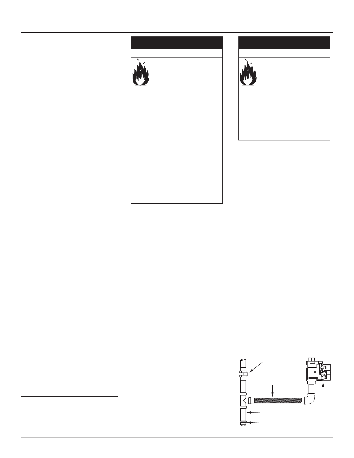
and no farther than 8’ from the water
heater’s inlet gas connecon.
4. Aer installing the posive lock-up gas
pressure regulator(s) an inial nominal
supply pressure seng of 7.0” w.c. for
Natural Gas and 11.0” w.c. for Propane
(LP) while the water heater is operang
is recommended and will generally
provide good water heater operaon.
Some addional adjustment may be
required later to maintain a steady gas
supply pressure.
5. When installing mulple water heaters
in the same gas supply system it is
recommended that individual posive
lock-up gas pressure regulators be
installed at each unit.
All gas piping must comply with local codes
and ordinances or with current edions of the
National Fuel Gas Code, ANSI Z223.1/NFPA 54.
Copper or brass tubing and ngs (except n
lined copper tubing) shall not be used.
If the gas control valve is subjected to pressures
exceeding 1/2 psi, the damage to the gas control
valve could result in a re or explosion from
leaking gas.
If the main gas line Shut-o serving all gas water
heaters is used, also turn o the gas at each
water heater. Leave all gas appliances shut o
unl the water heater installaon is complete.
A gas line of sucient size must be run to the
water heater. Consult the current edion of
the National Fuel Gas Code, ANSI Z223.1/NFPA
54 and your gas supplier concerning pipe size.
There must be:
• A readily accessible manual shut o valve
in the gas supply line serving the water
heater, and
• A sediment trap ahead of the gas control
valve to help prevent dirt and foreign
materials from entering the gas control
valve.
• A ground joint union of proper size
between the manual shut o valve and
gas control valve to permit servicing of
the unit.
Be sure to check all the gas piping for leaks
before lighting the water heater. Rinse off
soluon and wipe dry.
Gas Line Installation
Contact your local gas utility company to
ensure that adequate gas service is available
and to review applicable installaon codes for
your area.
Under certain circumstances, the
water heater can explode and catch
fire, resul�ng in property damage,
personal injury, or death.
Do the following to avoid these
condi�ons:
• Do not store or use gasoline or other
flammable vapors and liquids in the vicinity
of this or any other appliance.
• Avoid all ignition sources if you smell gas.
• Do not expose water heater controls to
excessive gas pressure.
• Use only the gas shown on the water
heater rating label.
• Maintain required clearances to
combustibles.
• Keep ignition sources away from faucets
after extended periods of non-use.
• Install sediment trap in accordance with
NFPA54
or
CSA-B1491.
• Read the instruction manual before
installing, using, or servicing the water
heater.
• Contact a qualified installer or service
agency for installation and service.
Fire and Explosion Hazard
⚠
WARNING
Be sure that the gas meter has sufficient
capacity to supply the rated gas input of the
water heater as well as the requirements of
all other gas red equipment supplied by the
meter. If the gas meter is undersized, the gas
company will have to install a properly sized
gas meter.
Make sure the gas supplied is the same type
listed on the water heaters rang label.
The gas piping must be installed according to
all local and state codes or in absence of local
and state codes with the current edion of the
National Fuel Gas Code, ANSI Z223.1/NFPA 54.
Schedule 40 Steel or Wrought Iron Pipe is the
preferred material for the gas line of this water
heater. It is imperative to follow the sizing
recommendaons in the latest version of the
National Fuel Gas Code, ANSI Z223.1/NFPA 54 if
corrugated stainless steel tubing (CSST) is used
as the gas line for this water heater.
Table 6 (page 23), Table 11 (page 30), and
Table 14 (page 34), and Table 16 (page 42)
are provided as a sizing reference for commonly
used gas pipe materials. Consult the National
Fuel Gas Code for the recommended gas pipe
size of other materials.
Contaminants in gas lines can cause
fire or explosion.
Do the following to avoid this
hazard:
• Clean all gas piping before
installation.
• Install sediment trap in accordance
with
NFPA54
or
CSA-B1491
.
• Be sure the junction box cover and the
access door covers are in place.
• These covers keep debris from
entering and potentially being ignited,
and help keep any internal fires from
spreading.
Fire and Explosion Hazard
⚠
WARNING
Follow the instrucons below and see Figure 52
and Figure 53 for gas piping installaon.
1. Apply thread sealing compounds (pipe
dope/thread-sealer
tape) sparingly and
only to the male threads of the pipe
joints. Do not apply sealing compound
to the rst two threads. Use pipe dope
or thread-sealer tape marked as being
resistant to the acon of liquid petroleum
(LP/propane) gases.
2. Install a readily accessible manual
shut-o valve in the gas supply line as
recommended by the local ulity. Know
the locaon of this valve and how to turn
o the gas to this unit.
3. Install a sediment trap as shown. The
sediment trap must be no less than 3”
long for the accumulaon of dirt, foreign
material and water droplets.
4. Install a ground union between the water
heater and the manual shut-o valve.
This is to allow easy servicing. See Figure
53 (page 42).
5. Turn the gas supply on and check for
leaks. See Gas Supply Line Leak Testing
(page 43).
Note: Units with inputs of 175,000 BTU/hr or
above must have a minimum of 3/4”
NPT gas pipe supplied to the water
heater.
Flexible Connector (properly sized
for the heater input rate)
Ground Joint Union
(op�onal)
Cap
Sediment Trap (3 inch minimum)
Gas Control
Valve
Figure 52. Flexible Pipe to Gas Valve
INSTALLING THE WATER HEATER
Residenal Condensing Gas Water Heaters • 41
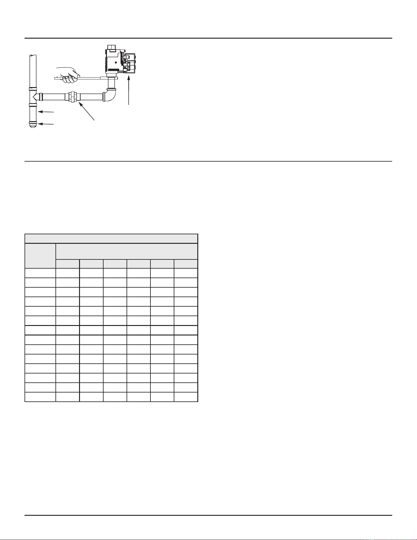
Cap
Sediment Trap
Ground Joint Union
(op�onal)
Gas Control
Valve
Figure 53. Black Pipe to Gas Valve
Note: Always secure the square on the gas
valve base with a suitable wrench when
ghtening or loosening the gas piping.
Gas Line Sizing
Depending on the developed equivalent length
and/or the number of appliances connected to
a common main, the size of supply gas lines may
have to be increased.
Size the supply/main gas line(s) in accordance
with Table 16 or Table 17.
The values given in Table 16 and Table 17 are for
straight lengths of iron pipe at 0.5” W. C. (125
Pa) pressure drop, which is considered normal
for low pressure systems.
Note: Fings such as elbows and tees will add
to the pipe pressure drop.
Schedule-40 Steel or wrought-iron pipe is the
preferred material for the gas line of this water
heater. It is imperative to follow the sizing
recommendaons in the latest version of the
National Fuel Gas Code if corrugated stainless
steel tubing (CSST) is used as the gas line for
this water heater.
Table 16. Supply Gas Line Sizing U. S. Units
Length in
Feet
Normal Iron Pipe Sizes (Inches)
Input In Thousands Btu/Hr
1/2” 3/4” 1” 1 1/4” 1 1/2” 2”
10
175 360 680 1400 2100 3960
20
120 250 485 950 1460 2750
30
97 200 375 770 1180 2200
40
82 170 320 660 990 1900
50
73 151 285 580 900 1680
60
66 138 260 530 810 1520
70
61 125 240 490 750 1400
80
57 118 220 460 690 1300
90
53 110 205 430 650 1220
100
50 103 195 400 620 1150
125
44 93 175 360 550 1020
150
40 84 160 325 500 950
175
37 77 145 300 460 850
200
35 72 135 280 430 800
INSTALLING THE WATER HEATER
42 • Residenal Condensing Gas Water Heaters
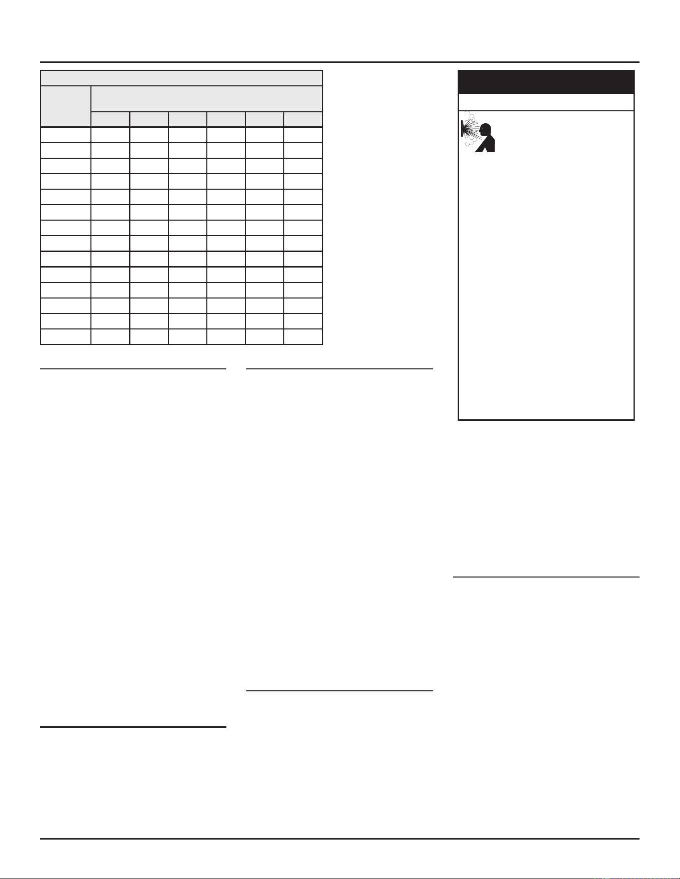
Table 17. Supply Gas Line Sizing Metric Units
Length In
Meters
Normal Iron Pipe Sizes (inches)
Input in kW
1/2” 3/4” 1” 1 1/4” 1 1/2” 2”
3.0
51 105 199 410 615 1160
6.1
35 73 142 278 428 805
9.1
28 59 110 225 346 644
12.2
24 50 94 193 290 556
15.2
21 44 83 170 264 492
18.3
19 40 76 155 237 445
21.3
18 37 70 143 220 410
24.4
17 35 64 135 202 381
27.4
16 32 60 126 190 357
30.5
15 30 57 117 182 337
38.1
13 27 51 105 161 299
45.7
12 25 47 95 146 278
53.3
11 23 42 88 135 249
61.0
10 21 40 82 126 234
Gas Supply Line Leak Testing
Any me work is done on the gas supply system
perform a leak test to avoid the possibility of
re or explosion.
1. For test pressures exceeding 1/2 psi
disconnect, the water heater and its
Main Gas Shuto Valve from the gas
supply piping system during tesng. See
Figure 2 (page 13). The gas supply
line must be capped when disconnected
from the water heater.
2. For test pressures of 1/2 psi or less, the
water heater need not be disconnected,
but must be isolated from the supply
gas line by closing the Main Gas Shuto
Valve during tesng.
3. Paint all supply gas line joints and
connecons upstream of the water
heater with a chloride-free liquid
soluon to test for leaks. Bubbles
indicate a gas leak. Do not use matches,
candles, ame or other sources of
ignion for this purpose.
4. Repair any leaks before placing the water
heater in operaon.
Gas Supply Line Purging
Gas line purging is required with new piping or
systems. Purging should be performed per the
current edion of the National Fuel Gas Code,
ANSI Z223.1/NFPA 54.
Water Heater Gas Leak Testing
The following are procedure guidelines
for detecting gas leaks in gas water heater
connecons, including the gas valve, the valve
train, and other system components.
A chloride-free liquid solution is the only
approved fuel gas or combuson product leak
vericaon method. Paint suspected leak points
with a liquid soluon to test for leaks. Bubbles
indicate a fuel gas or combuson product leak.
Do not use matches, candles, ame or other
sources of ignion for this purpose.
Use of a leak-detecon device shall be limited
to idencaon of a potenal source of leakage
with the actual leak confirmed by using a
chloride-free liquid soluon as described above.
When using a leak-detecon device the p of
the probe shall be no less than 2” (50 mm) from
the suspected leak point. If no leak is detected
with a leak detecon device, no vericaon is
required with a liquid soluon.
Note: Servicing should only be performed by
a qualied service technician.
HIGH ALTITUDE INSTALLATIONS
This high eciency water heater is cered
for use without modicaon for an altude
of 10,100 feet (3,078 m). Consult the factory
for installaon at altudes over 10,100 feet
(3, 078 m).
Breathing carbon monoxide can
cause brain damage or death.
Do the following to avoid carbon
monoxide poisoning:
• Install vent system in accordance with
codes.
• Special consideration must be taken with
installations above 10,100 ft. (3,079 m).
Refer to the high altitude section of this
manual.
• Do not operate if there is soot build-up.
•
Do not obstruct water heater air intake with
insulating jacket or blanket.
• Do not place chemical vapor emitting
products near the water heater.
• Gas and carbon monoxide detectors are
available.
•
Never operate the heater unless it is vented
to the outdoors and has adequate air
supply to avoid risks of improper operation,
fire, explosion, or asphyxiation.
• Analyze the entire vent system to make
sure that condensate will not become
trapped in a section of vent pipe and
therefore reduce the open cross sectional
area of the vent.
• Always read and understand instruction
manual.
Breathing Hazard
WARNING
⚠
Some gas ulity companies derate their gas for
altude, making it unnecessary to install high
altude orices. Call the local gas or ulity
company to verify BTU content.
Due to the input rate reducon at high altudes,
the output rang of the water heater is also
reduced and should be compensated for in
the sizing of the equipment for applicaons.
See Combustion Air and Ventilation (page 21).
CONNECTING THE WATER SUPPLY
Note that all piping and components
connected to the water heater must be
suitable for use with potable water.
1. Determine the type of water pipes in
your home. Most homes use copper
water pipes, but some use CPVC or cross-
linked polyethylene (PEX). Use ngs
appropriate for the type of pipe in your
home. Do not use iron or PVC pipe – they
are not suitable for potable water.
2. Connect the cold water supply using ¾
inch Naonal Pipe Thread “NPT” to the
cold water inlet nipple.
For ease of removing the water heater
for service or replacement, connect the
water pipes with a coupling called a
union. We recommend using a dielectric-
type union (available at your local
INSTALLING THE WATER HEATER
Residenal Condensing Gas Water Heaters • 43
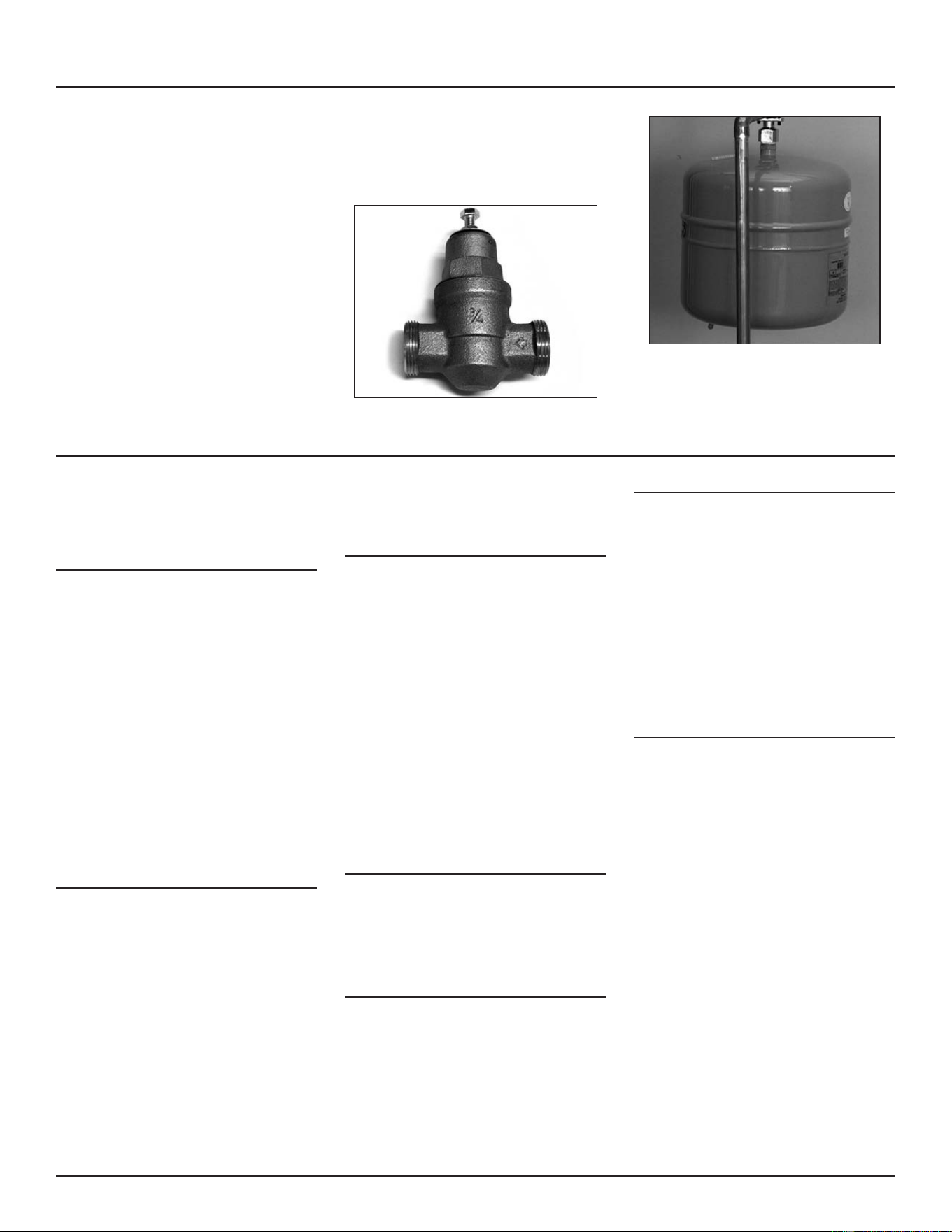
plumbing supplier). Dielectric unions
can help prevent corrosion caused by
ny electric currents common in copper
water pipes and can help extend the life
of the water heater.
NOTICE: Most water heater models
contain energy saving heat traps in the
inlet and outlet connecons. Do not
remove the heat traps.
3. Connect the hot water supply using ¾”
NPT to the hot water outlet. Follow the
same connecon guidelines as for the
cold water supply.
4. Install insulaon (or heat tape) on the
water pipes especially if the indoor
installaon area is subject to freezing
temperatures. Insulang the hot water
pipes can increase energy eciency.
5. Adjust (or install) the home’s Pressure
Reducing Valve to 50-60 psi and install a
Thermal Expansion Tank.
Figure 54. A Pressure Reducing Valve is required if your
home’s water pressure is above 80 psi.
Figure 55. The Thermal Expansion Tank should be
pressurized with air to match the home’s incoming water
pressure.
INSTALLATION CHECKLIST
Note: Use and complete this checklist
before lighting the heater. Correct
any condions that do not meet these
instrucons.
Water Heater Location
Centrally located with the water piping
system. Located as close to gas piping
and vent pipe system as possible.
Located indoors and in a vertical position.
Protected from freezing temperatures.
Proper clearances from combustible
surfaces maintained and not installed
directly on a carpeted floor.
Provisions made to protect the area from
water damage. Metal drain pan installed
and piped to an adequate drain.
Installation area free of corrosive ele-
ments and flammable material.
Sufficient room to service the water
heater.
Gas Supply And Piping
Gas supply is the same type as listed on
the water heater data plate.
Gas line equipped with shut-off valve,
union and sediment trap.
Approved pipe joint compound used.
Adequate pipe size and of approved
material.
Chloride-free solution or other approved
means used to check all connections and
fittings for possible gas leaks.
Vent Pipe System
Vent pipe and fittings of approved mate-
rial.
Acceptable size, length and number of
elbows on exhaust vent system.
Installed in accordance with prevail-
ing provisions of local codes, or in the
absence of such, the latest edition of
National Fuel Gas Code, ANSI Z223.1/NFPA
54.
Horizontal piping slopes at an upward
pitch of 1/8” rise per 5’ away from the
water heater.
Not obstructed in any way.
Means installed to collect, neutralize (if
required) and dispose of condensate.
Vent Termination
Horizontal
12” min. above grade/snow level.
Away from corners, other vents, win-
dows etc.
Vertical
Air Intake and Exhaust terminations 18”
min. above roof/snow level.
Water System Piping
Temperature and Pressure relief valve
properly installed with a discharge line
run to an open drain and protected from
freezing.
All piping properly installed and free of
leaks.
Heater completely filled with water.
Closed system pressure build-up precau-
tions installed.
Thermostatic Mixing Valves installed at
each point-of-use.
Electrical Connections
Unit connected to a 120 V electrical sup-
ply. A dedicated circuit is preferred. Do
not use a GFI outlet.
Proper polarity.
Water heater properly grounded.
Installed in accordance with prevail-
ing provisions of local codes, or in the
absence of such, the latest edition of
National Electrical Code (NFPA 70).
After all actions on checklist are checked/
completed, read the Lighng Instrucons and
proceed with lighng the heater.
INSTALLING THE WATER HEATER
44 • Residenal Condensing Gas Water Heaters
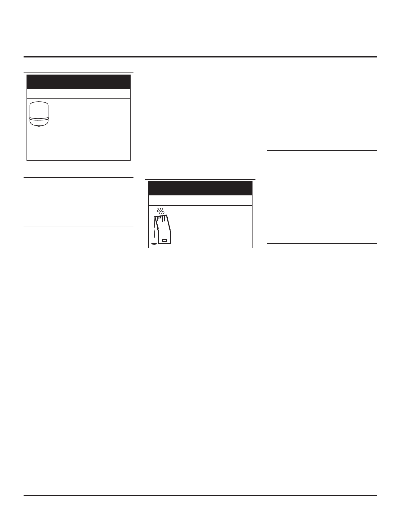
START UP AND OPERATIONS
START UP CONDITIONS
A water heater installed in a closed
water system can be damaged by
normal variations in pressure.
If the water heater is to be installed
in a closed water system, install a thermal
expansion tank or device to prevent pressure
changes from damaging the water heater.
Contact a qualified installer or service agency.
Property Damage Hazard
⚠
CAUTION
SMOKE/ODOR
It is not uncommon to experience a small
amount of smoke and odor during the inial
start-up. This is due to burning o of oil from
metal parts, and will disappear in a short while.
PRIOR TO START UP
Installaon and start up of this water heater
requires abilies and skills equivalent to that
of a licensed tradesman in the eld involved.
See Qualications (page 10).
DO NOT USE THIS APPLIANCE IF ANY PART
HAS BEEN EXPOSED TO FLOODING OR WATER
DAMAGE. Immediately call a qualied service
technician to inspect the water heater and to
make a determinaon on what steps should
be taken next.
Light the water heater in accordance with the
Lighng and Operaon Instrucon label on the
water heater and in this manual.
The water heaters covered by this manual
are equipped with an electronic control
system which automatically sequences the
Combustion Blower, pre- and post-purging
of the combuson chamber, the Hot Surface
Igniter, the 24 Volt Gas Control Valve, Main
Burner Ignion, and ame sensing. The control
system will lock out aer three unsuccessful
ignion aempts. The control will reset itself
aer 15 minutes. See Control System Operation
(page 49).
Before aempng start up, thoroughly study
and familiarize yourself with the exact sequence
of operaon. See Basic Sequence Of Operation
(page 55), Burner Ignition Sequence (page
55). Ensure the water heater is properly
grounded. Flame sensing requires an adequate
earth ground. If the water heater is not properly
grounded it will cause Ignition Failure. See
Electrical Wiring (page 40).
Be certain that the water heater is full of water,
that air is purged from the gas and water lines
and that there are no leaks in the gas and water
lines. Ensure all inlet water valves are open.
FILLING THE WATER HEATER
Operating the water heater without
water will cause damage to it.
To avoid water heater damage, fill
tank with water before operating.
Property Damage Hazard
⚠
CAUTION
Never use this water heater unless it is
completely full of water. To prevent damage
to the tank, the tank must be lled with water.
Water must ow from the hot water faucet
before turning ON gas to the water heater.
To ll the water heater with water:
1. Locate the drain valve at the base of the
water heater behind the access panel.
See Features and Components (page
13).
2. Close the water heater drain valve
by turning the handle to the right
(clockwise).
3. Open the cold water supply valve to the
water heater.
Note: The cold water supply valve must be le
open when the water heater is in use.
4. To insure complete lling of the tank,
allow air to exit by opening the nearest
hot water faucet. Allow water to run
unl a constant ow is obtained. This
will let air out of the water heater and
piping.
5. Check all water piping and connecons
for leaks. Repair as needed. See
Checking for leaks (page 57).
INITIAL START UP
Required Test Equipment
• One U-tube manometer, recommended
ranges; 0-14” w.c. and 0-35” w.c. or
pressure gauges.
• One digital manometer can be used in
place of U-tube manometers or pressure
gauges. Recommended ranges; -14.00
to +14.00” w.c. resoluon 0.01” w.c. and
0-35” w.c. resoluon 0.10” w.c.
Note: All test equipment must be acclimated
to ambient temperature before
calibraon and use.
Preparation
1. Using the control system menus, change
the temperature setpoint to the lowest
temperature seng. See Temperature
Setpoint (page 49).
2. Close the manual gas shut o valve. See
Figure 2 (page 13).
3. Wait ve (5) minutes for any residual gas
to clear.
4. Open the Main Gas Shuto Valve.
5. Measure and record the supply gas
pressure, this is a “stac” supply gas
pressure reading; while the water heater
is not ring. Adjust supply gas pressure
as necessary. See Gas Supply System
Installation (page 40).
Residential Condensing Gas Water Heaters • 45
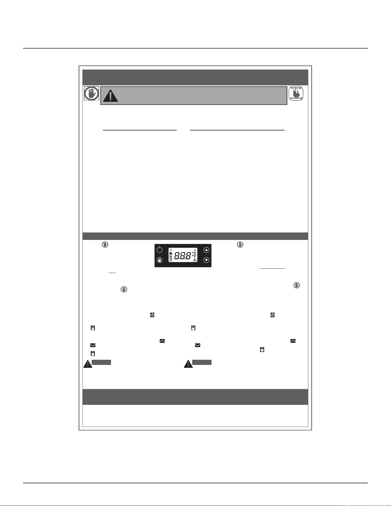
Lighting The Water Heater
The instrucon label below is axed to the
water heater’s covered by this manual at the
factory and must be followed when lighng and
operang the water heater.
100321847
1. Débranchez le chauffe-eau de la prise 120 Vca/60 Hz lors de tout
entretien.
2. Débranchez le chauffe-eau de la prise 120 Vca/60 Hz lors de tout
entretien.
1. Unplug the power cord from the 120Vac 60Hz outlet if
service is to be performed.
2. Set the Main Manual Gas Shut-Off Valve to the OFF
position.
COUPER L’ALIMENTATION
EN GAZ DE L’APPAREIL
TO TURN OFF GAS
TO APPLIANCE
1. ARRÊTEZ! Lisez les directives de sécurité au
haut de cette étiquette.
2. Débranchez le cordon d’alimentation de la prise
électrique 120 Vca/60 Hz.
3. Le brûleur de cet appareil est muni d’un dispositif
d’allumage automatique. Ne tentez pas d’allumer le
brûleur manuellement.
4. Poussez l’interrupteur de la commande du gaz à la position “OFF”.
5. Attendez cinq minutes afin de laisser se dissiper tout gaz ayant pu
s’accumuler. Si vous détectez une odeur de gaz, ARRÊTEZ!
Passez à l’étape B des instructions de sécurité dans la partie
supérieure de cette étiquette. Si vous ne détectez pas d’odeur de
gaz, passez à la prochaine étape.
6. Poussez l’interrupteur de la commande du gaz à la position “ON”.
7. Branchez le cordon d’alimentation à une prise électrique 120 Vca/60
Hz.
8. Lancez le chauffage en appuyant sur le bouton (ON/OFF)
pendant 3 secondes.
9. Si l’icône “Verrou” s’affiche à l’écran, appuyez sur le bouton
(Verrouiller/Déverrouiller) pendant 5 secondes pour déverrouiller
le module de commande.
10. La température de consigne par défaut est de 60°C (140°F). Pour
modifier ce paramètre, appuyez plusieurs fois sur le
bouton (Plus) ou (Moins) jusqu’à ce que la température de
l’eau souhaitée s’affiche à l’écran. Appuyez sur le bouton
(Verrouiller/Déverrouiller) dans les 10 secondes pour accepter la
nouvelle température de consigne.
DANGER plus l’eau est chaude, plus le risque
d’ébouillantage est élevé. Consultez les directives du manuel
à ce sujet avant de régler la température.
11. Si l’appareil ne se met pas en marche, suivez la directive “COUPER
L’ALIMENTATION EN GAZ DE L’APPAREIL” et appelez un
technicien ou le fournisseur de gaz.
DANGER
1. STOP! Read the safety
information above on this label.
2. Unplug the power cord from the
120Vac 60Hz outlet.
3. This appliance is equipped with a
device which automatically lights the
burner. Do not try to light the burner by hand.
4. Set the Main Manual Gas Shut-Off Valve to the OFF
position.
5. Wait five (5) minutes to clear out any gas. If you then
smell gas, STOP! Follow "B" in the safety
information above on this label. If you don't smell
gas, go to the next step.
6. Set the Main Manual Gas Shut-Off Valve to the ON
position.
7. Plug the power cord into a 120Vac 60Hz outlet.
8. Turn ON the heater by pressing the (ON/OFF)
button for 3 seconds.
9. If the “Lock” icon on the display is showing, press the
(Lock/Unlock) button for 5 seconds to unlock the
control.
10. The default setpoint for water temperature is 60°C
(140°F). To change this setting, press the (Plus) or
(Minus) button repeatedly until the desired water
temperature is indicated on the display. Press the
(Lock/Unlock) button within 10 seconds to accept
the new water temperature setpoint.
DANGER Hotter water increases the risk of
scald injury. Consult the instruction manual
before changing temperature.
11. If the appliance will not operate, follow the instructions
"TO TURN OFF GAS TO APPLIANCE" and call your
technician or gas supplier.
DANGER
INSTRUCTIONS D’UTILISATIONOPERATING INSTRUCTIONS
A. Cet appareil n’est pas équipé d’une veilleuse. Le brûleur est plutôt
muni d’un dispositif d’allumage automatique.
NE tentez PAS d’allumer le brûleur manuellement.
B. AVANT LA MISE EN MARCHE, humez tout autour de l’appareil
afin de déceler une éventuelle odeur de gaz. Sentez aussi près du
sol, car certains gaz sont plus lourds que l’air et s’y accumulent.
SI VOUS DÉTECTEZ UNE ODEUR DE GAZ:
• Ne mettez aucun appareil en marche.
• Ne pas toucher à aucun interrupteur; ne pas se servir des
téléphones se trouvant dans le bâtiment.
• Appelez immédiatement votre fournisseur de service du gaz de
chez un voisin et suivez ses directives.
• Si vous ne pouvez communiquer avec votre fournisseur de gaz,
appelez le service des incendies.
C. Ne vous servez que de vos mains pour appuyer sur les boutons
du module de commande, n’utilisez jamais d’outils. Si vous
n’arrivez pas à actionner les boutons du module de commande,
ne tentez pas de les réparer. Faites plutôt appel à un technicien
d’entretien qualifié. Si vous forcez ou tentez de réparer le bouton,
il a risque d’explosion ou d’incendie.
D. N’utilisez pas cet appareil même s’il n’a été que partiellement
submergé par de l’eau. Communiquez immédiatement avec un
installateur qualifié ou un centre de service afin de faire remplacer
tout chauffe-eau ayant été submergé lors d’une inondation. Ne
tentez jamais de réparer l’appareil. Il doit être remplacé!
A. This appliance does not have a pilot. It is equipped
with an ignition device which automatically lights the
burner. Do NOT try to light the burner by hand.
B. BEFORE OPERATING smell all around the
appliance area for gas. Be sure to smell next to the
floor because some gas is heavier than air and will
settle on the floor.
WHAT TO DO IF YOU SMELL GAS:
• Do not try to light any appliance.
• Do not touch any electric switch; Do not use any
phone in your building.
• Immediately call your gas supplier from a
neighbor's phone. Follow the gas suppliers
instructions.
• If you cannot reach your gas supplier, call the fire
department.
C. Use only your hand to push in the control module
buttons. Never use tools. If the control buttons will
not push in, don't try to repair them, call a qualified
service technician. Force or attempted repair may
result in a fire or explosion.
D. Do not use this appliance if any part has been under
water. Immediately contact a qualified installer or
service agency to replace a flooded water heater.
Do not attempt to repair the unit. It must be
replaced!
AVANT LA MISE EN MARCHE: LE RÉSEAU D’ALIMENTATION EN EAU DOIT
ÊTRE ENTIÈREMENT REMPLI D’EAU ET L’AIR ENTIÈREMENT PURGÉ.
BEFORE OPERATING: ENTIRE SYSTEM MUST BE FILLED
WITH WATER AND AIR PURGED FROM ALL LINES.
INFLAMMABLE
FLAMMABLE
WARNING: If you do not follow these instructions exactly, a fire or explosion may result
causing property damage, personal injury or loss of life.
AVERTISSEMENT: Tout manquement aux présentes directives peut causer un incendie
ou une explosion résultant en des dommages matériels, des blessures ou la mort.
POUR VOTRE SÉCURITÉ,
LISEZ AVANT L’ALLUMAGE
FOR YOUR SAFETY
READ BEFORE LIGHTING
Install Thermostatic Mixing Valves (temperature limiting valves) at
each point-of-use to reduce the risk of scalding.
Installer des mélangeurs thermostatiques (limiteurs de température)
à chaque point d’utilisation pour réduire le risque d’échaudage.
ENVIRON 0,5 SECONDE
ENVIRON 1,5 SECONDE
MOINS DE 5 SECONDES
ENVIRON 30 SECONDES
PLUS DE 5 MINUTES
160°F (71°C)
150°F (65°C)
140°F (60°C)
130°F (54°C)
120°F (49°C)
ABOUT 1/2 SECOND
ABOUT 1 1/2 SECONDS
LESS THAN 5 SECONDS
ABOUT 30 SECONDS
MORE THAN 5 MINUTES
160°F (71°C)
150°F (65°C)
140°F (60°C)
130°F (54°C)
120°F (49°C)
DÉLAI D’ÉBOUILLANTAGE
(BRÛLURE AU 2
e
ET 3
e
DEGRÉ
SUR LA PEAU D’UN ADULTE)
THERMOSTAT –
VOIR LE MANUEL
D’INSTRUCTIONS
TIME TO PRODUCE
2nd & 3rd DEGREE
BURNS ON ADULT SKIN
TEMPERATURE
SETTING, SEE
INSTRUCTION MANUAL
HOT
BURN
CHAUDE
BRÛLURE
L'eau, à une température supérieure à 125°F (51°C), peut
instantanément causer des brûlures graves ou entraîner
la mort.
Le risque de brûlures est plus élevé chez les enfants, les
personnes handicapées et les personnes âgées.
Lisez la notice d'instruction avant de régler la
température du chauffe-eau.
Vérifier la température de l'eau avant de prendre un bain
ou une douche.
Des robinets limiteurs de température sont disponibles.
Consultez la notice.
Water temperature over 125°F (51°C) can cause severe
burns instantly or death from scalds.
Children, disabled and elderly are at highest risk of being
scalded.
See instruction manual before setting temperature at
water heater.
Feel water before bathing or showering.
Temperature limiting valves are available, see manual.
DANGER
Figure 56. Lighting Instructions Label
46 • Residential Condensing Gas Water Heaters
TEMPERATURE REGULATION
Install Thermostac Mixing Valves to regulate
the temperature of the water supplied to
each point-of-use (for example, kitchen sink,
bathroom sink, bath, shower). Install and adjust
the mixing valve according to its manufacturer’s
instrucons. See Figure 46 (page 35).
It is recommended that lower water
temperatures be used to avoid the risk of
scalding. It is further recommended, in all
cases, that the water temperature be set for
the lowest temperature which sases your
hot-water needs. This will also provide the most
energy ecient operaon of the water heater.
Short repeated heang cycles caused by small
hot-water uses can cause a temperature
increase of the hot water by 30F° higher than
the heater’s temperature settings. If you
experience this type of use you should consider
using lower temperature sengs to reduce
scald hazards.
WARNING! Even if the water heater’s control
system is set to a relavely low temperature,
hot water can scald. Install Thermostatic
Mixing Valves at each point-of-use to reduce
the risk of scalding. See Figure 46 (page 35).
Should overheang occur or the gas supply fails
to shut o, turn o the main manual gas shut o
valve to the appliance. See Figure 2 (page 13).
TEMPERATURE CONTROL
Water temperature over 125°F
(52°C) can cause severe burns
instantly resul�ng in severe injury
or death.
Observe the following precau�ons to avoid
this hazard:
• Children, the elderly, and the physically or
mentally disabled are at highest risk for scald
injury.
• Feel water before bathing or showering.
• Temperature limiting devices, such as
thermostatic point-of-use mixing valves must
be installed when required by codes and to
ensure safe temperatures at fixtures.
• The thermostat(s) on this water heater
has been factory set to approximately
120°F to reduce the risk of scalding. Higher
temperatures increase the risk of scalding,
but even at 120°F, hot water can scald. If you
choose a higher temperature, thermostatic
mixing valves, located at each point-of-use
are particularly important to help avoid
scalding.
• Thermostatic mixing valves located at each
point of use are particularly important to
avoid scalding.
Burn Hazard
⚠
DANGER
HOT WATER CAN SCALD
Water heaters are intended to produce hot
water. Water heated to a temperature which
will sasfy space heang, clothes washing, dish
washing, cleaning and other sanizing needs
can scald and permanently injure you upon
contact. Some people are more likely to be
permanently injured by hot water than others.
These include the elderly, children, the inrm,
or physically/mentally handicapped. If anyone
using hot water ts into one of these groups
or if there is a local code or state law requiring
certain temperature water at the hot-water
tap, then you must take special precauons. In
addion to using lowest possible temperature
seng that sases demand of applicaon, to
reduce the risk of scalding, install Thermostac
Mixing Valves (temperature limiting valves)
at each point-of-use. See Figure 46 (page
35).These valves automatically mix hot and
cold water to limit the temperature at the tap.
Before changing the factory setting on the
control system, see Table 18.
This water heater is equipped with a control
system. See Figure 57 (page 49). Hot
water temperatures required for automac
dishwasher and laundry use can cause scald
burns resulng in serious personal injury and/
or death. The temperature at which injury
occurs varies with the person’s age and me
of the exposure. The slower response me of
children, aged or disabled persons increases the
hazards to them. Never allow small children to
use a hot-water tap, or to draw their own bath
water. Never leave a child or disabled person
unaended in a bathtub or shower.
Seng the water heater temperature at 120 °F
will reduce the risk of scalds.
Higher temperatures over 120°F
(49°C) can cause severe burns
instantly resul�ng in severe injury or
death.
To reduce the risk of unusually hot water
reaching the fixtures in the house, install
thermosta�c mixing valves at each point of
use.
Burn Hazard
⚠
WARNING
See Figure 46 (page 35)
Residential Condensing Gas Water Heaters • 47
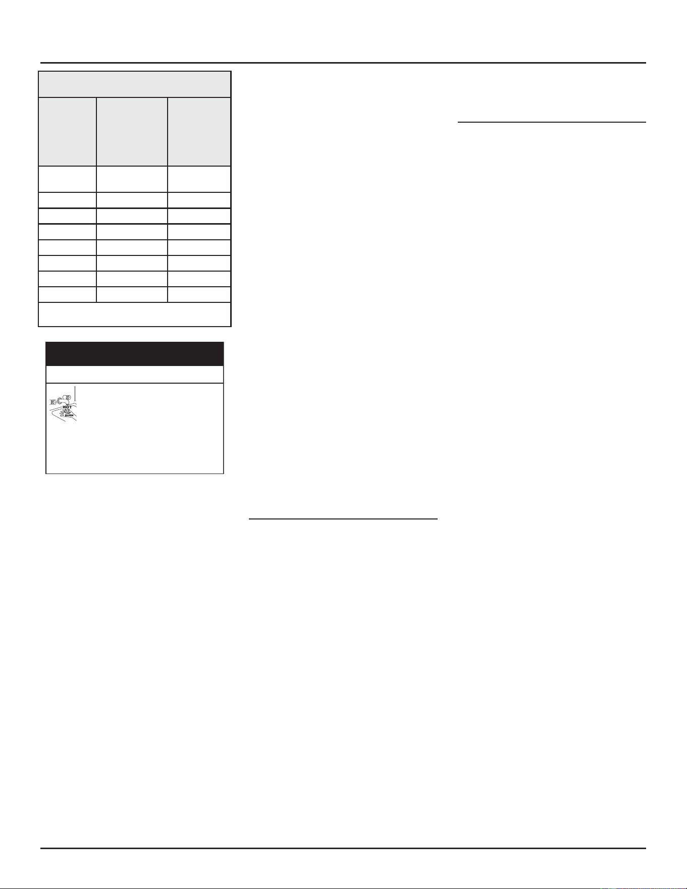
Table 18. Burn Time at Various
Temperatures
Water
Temperature
°F (°C)
Time for 1st
Degree Burn
(Less Severe
Burns)
Time for
Permanent
Burns
2nd & 3rd
Degree
(Most Severe
Burns)
110 (43) (normal shower
temp.)
116 (47) (pain threshold)
116 (47) 35 minutes 45 minutes
122 (50) 1 minute 5 minutes
131 (55) 5 seconds 25 seconds
140 (60) 2 seconds 5 seconds
149 (65) 1 second 2 seconds
154 (68) instantaneous 1 second
(U.S. Government Memorandum, C.P.S.C., Peter L.
Armstrong, Sept. 15, 1978)
Higher temperatures over 120°F
(49°C) can cause severe burns
instantly resul�ng in severe injury
or death.
To reduce the risk of unusually hot water
reaching the fixtures in the house, install
thermostatic mixing valves at each point of
use.
Burn Hazard
DANGER
⚠
Check water temperature at several points
of use in your home (for example, bathtub
faucet, shower, or lavatory sink) and adjust
the Thermostac Mixing Valves as needed. See
Figure 46 (page 35).
The water heater should be located in an area
where the general public does not have access
to set temperatures.
Seng the water temperature setpoint at 120°F
will reduce the risk of scalds. Some states require
sengs at specic lower temperatures. Check
with the code authority having jurisdicon.
The water heaters covered in this manual are
equipped with an electronic control system to
regulate water temperature inside the storage
tank. The control system senses temperature
from a factory installed temperature probe
installed on the side of the storage tank. See
Figure 2 (page 13) and Figure 3 (page 13).
The water temperature setpoint is adjusted to
regulate water temperature inside the tank.
This is an adjustable user seng in the control
system’s “Temperature Menu.” This and all
control system menus are accessed through
the UIM (user interface module) located on
the front of the water heater. See Figure 57
(page 49).
The water temperature setpoint is adjustable
from 90°F (32°C) to 160°F (71°C). The factory
seng is 120°F (49°C). See Temperature Setpoint
(page 49) for instrucons on how to adjust
the setpoint and other sengs.
Set the water temperature setpoint at the
lowest seng which produces acceptable hot
water supply. This will always provide the most
ecient operaon.
Note: When there will be no domesc hot
water demand for an extended period of
me, the temperature set point should
be set at 90°F to prevent “Stacking” and
T&P discharge.
HIGH TEMPERATURE APPLICATIONS
Higher operating temperatures cause more
wear on all water heaters and will decrease
the life span of the water heater. Consider
installing a small booster water heater for high
temperature applicaons to raise the outlet
temperature from the larger primary water
heater to the desired point of use temperature.
Contact your local distributor or call technical
support phone number listed on front page of
this manual for further technical assistance.
HIGH TEMPERATURE LIMIT CONTROL (ECO)
This water heater is equipped with an
ECO (energy cut out) non-adjustable high-
temperature limit designed to protect against
excessively high water temperatures inside
the water heater’s storage tank. The Control
board constantly monitors the state of the
temperature sensor thermistors. If the ECO
activates due to abnormally high water
temperature (approximately 190°F), the Control
Board will lock out and display fault code E00
on the UIM.
If the ECO acvates due to abnormally high
water temperatures in the storage tank, the
control system will immediately de-energize
the Gas Control Valve and end current heang
cycle. The control system will lock out disabling
further heang operaon. It is important that
a Qualied Service Technician be contacted
to determine the reason for ECO acvaon
before reseng the ECO. Once the reason has
been determined and corrected the ECO can
be reset as follows:
If the ECO acvates, water temperature must
drop below 140°F before the control system
can be reset. Once water temperature has
cooled below this point, the Control Board
must be reset. To reset the Control Board, do
the following:
1. Unlock the buons (by pressing the
Lock/Unlock buon for 3 seconds), if the
interface is locked
2. Simultaneously press the ON/OFF and
Plus (SW3) buons for 3 seconds.
See Figure 57 (page 49) for the button
locaons.
TEMPERATURE REGULATION
48 • Residenal Condensing Gas Water Heaters
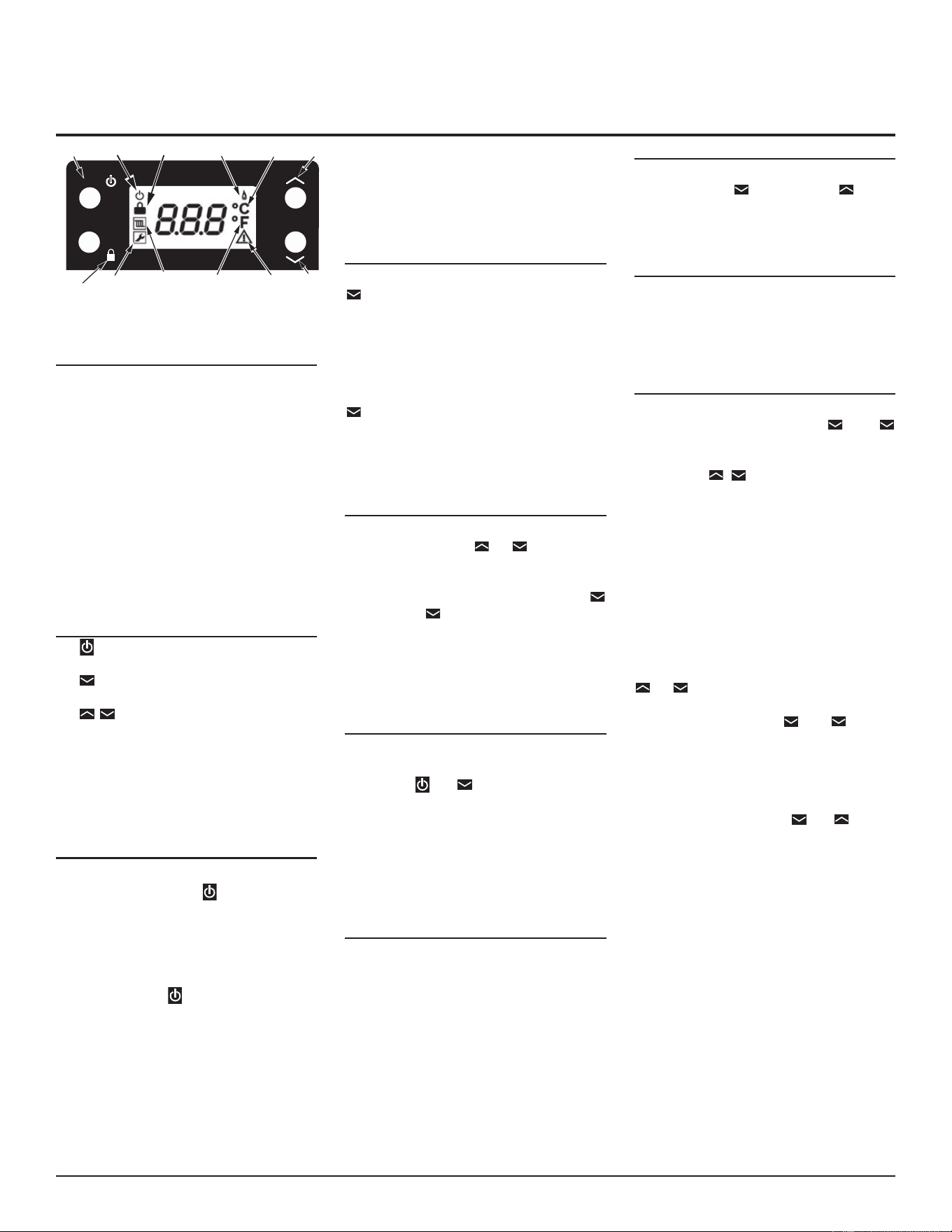
CONTROL SYSTEM OPERATION
ON/OFF
ENTER
LOCK/
UNLOCK
SERVICE
RADIATOR
(NOT IN USE)
FAHRENHEIT
WARNING
MINUS
ON/OFF ON/OFF LOCK FLAME ON CELSIUS PLUS
Figure 57. LCD Display
ICONS
• ON/OFF: visible when heater has power
but is OFF.
• LOCK: visible when keypad locked.
• RADIATOR: not used
• SERVICE: visible when heater is in service
modes.
• FLAME: visible when burner is in run
mode.
• CELSIUS: visible when a temperature is
shown and the unit is °C.
• FAHRENHEIT: visible when a temperature
is shown and the unit is °F.
• WARNING: ashing during fault
condions.
BUTTONS
• (ON/OFF) - This buon is used to
switch On/O the heater.
• (Lock/Unlock) - This buon is used to
Lock/ Unlock the control.
• (Plus and Minus) - These two
buons are used to make changes of the
setpoint and to navigate throughout the
menus.
Combinaons of the buons are used for other
funcons, as per the following paragraphs:
ON/OFF
When the heater is OFF the only active
(unlocked) buon is the buon. The LCD
display shows only the ON/OFF icon. This icon
informs the user that the heater is connected
to electric power. When in OFF, the heater
completely ignores the call for heat and never
ignites the burner. The user can turn the heater
ON by pressing the buon for 3 seconds.
When the heater is ON, the ON/OFF icon is not
shown. Setpoint/Error codes are shown on LCD.
Lock/Unlock, °C, °F, ame, service and warning
icons are acve and shown according to heater
status and seng.
LOCK/UNLOCK
The control can be locked either by pressing the
buon for 3 seconds or automacally aer
30 seconds without pressing any buon. When
the control is locked the LCD will return to
display the setpoint (or error code if in a fault
state). When the control is locked and any
buon is pressed the lock icon on LCD will ash
twice per second. To unlock the control press
buon for 5 seconds and the lock icon on
LCD will turn o. When the control is locked the
Temperature setpoint cannot be changed and
the operang mode cannot be changed.
TEMPERATURE SETPOINT
To adjust the temperature setpoint, unlock the
control and press the or buons unl
reaching the desired value. The new value will
ash on the LCD display twice per second. To
validate the new setpoint, short press the
buon. If the buon is not pressed within
10 seconds, the new value will start to ash on
the display, and the setpoint goes back to the
previous value being connuously shown on
LCD.
NORMAL MODE / VACATION MODE
The user can quickly change from the normal
mode to the vacaon mode (and vice versa) by
pressing the and buons simultaneously.
In vacaon mode the setpoint is 60°F and the
differential is 10F° independently of the
outdoor temperature. In Normal mode the LCD
will display the actual setpoint set by the user,
in Vacation mode the LCD will display the
vacaon setpoint.
BURNER IN OPERATION
When the burner is in operaon and the ame
is detected by the ame sensor, the ame icon
on LCD is on.
SWITCHING BETWEEN TEMPERATURE UNITS
To switch temperature units (°F/°C), unlock the
control and press buon and the buon
simultaneously. The corresponding icon on LCD
°F or °C will be on.
FAULT INDICATION
If an error condion exists or a warning is in
place, the LCD shows the setpoint for 1 second
and error code for 1 second. The warning icon
will ash once per second.
SERVICE MODE
To enter in the service mode, Unlock the control
and simultaneously press the and
buons for 3 seconds. In service mode the
service icon is on. While in service mode,
pressing the / buons allows for cycling
between service codes. The numeric display will
show the service code for 1 second, followed
by the actual measurement displayed for 3
seconds.
Example: H06-5.00 represents the service code
of “H06 Blower RPM target” and the value of
“5.00” is the blower speed (5.00x1000 = 5,000
rpm).
The display will connue to show the service
code and the measurement value unless the
or buons are pressed to cycle to the
next item. To exit Service mode once again
simultaneously press the and buons
for 3 seconds. If no buon is pressed for 30
seconds the unit will revert back to operaon
mode where the setpoint is displayed and the
control is locked.
Simultaneously pressing the and buons
again will conrm the new altude seng and
also exit altude seng and revert back to
“Service mode”.
Residential Condensing Gas Water Heaters • 49
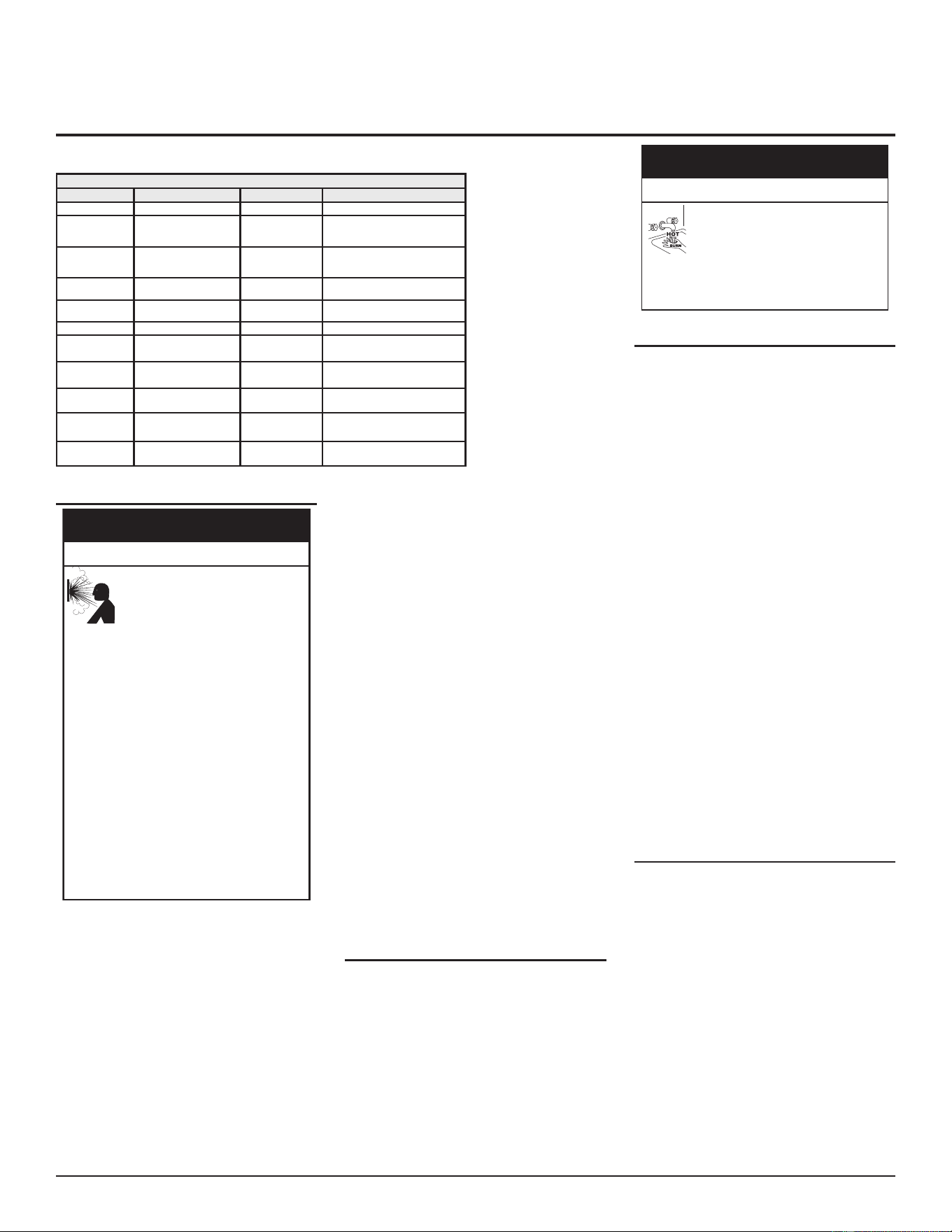
MAINTENANCE
Table 19. Maintenance Schedule
Component Operation Interval Reference
Tank Drain and Flush Every 6 Months See Draining and Flushing.
Tank
Lime Scale Removal
(Water Less Than 25
Grains Hard)
Not Required N/A
Tank
Lime Scale Removal
(Water Greater Than 25
Grains Hard)
Annually See Lime Scale Removal.
Burner Flames Inspecon Every 3 Months
See Burner Operation And
Inspection (page 51).
Burner Inspecon/Cleaning As Needed
Contact qualied agency or profes-
sional.
Moving Parts Lubricaon Not Required N/A
Powered Anodes Inspecon/Cleaning Annually
See Anode Rod Maintenance (page
52).
T&P Valve Test Operaon Semi Annually
See Temperature-Pressure Relief
Valve Test (page 52).
Vent System Inspecon Annually See Venting System Inspection.
Condensate
Neutralizaon
Inspecon Annually
See manual for the condensate
neutralizaon kit.
Condensate Col-
lecon
Cleaning Annually See Venting System Inspection.
VENTING SYSTEM INSPECTION
Flu gases, which can contain
carbon monoxide, can escape
if the vent pipe is not properly
installed. Breathing carbon
monoxide can cause brain damage or death.
Do the following to prevent this:
• Be alert for an obstructed, sooted, or
deteriorated vent system.
• Do not store corrosive chemicals in the
vicinity of the water heater because they
can cause chemical corrosion of the flue
and vent system.
• Analyze the entire vent system to make
sure that condensate will not become
trapped in a section of vent pipe and
therefore reduce the open cross sectional
area of the vent.
• Always read and understand the instruction
manual.
• Install gas and carbon monoxide detectors
in the vicinity of the water heater.
Fire and Explosion Hazard
WARNING
⚠
At least once a year a visual inspecon should
be made of the venng system. You should:
• Check for obstrucons and/or
deterioraon of the intake air and/
or vent piping and the intake air and
vent terminaons. The combuson
and venlaon air ow must not be
obstructed. Repair and/or replace
immediately as necessary.
Note: Do not reach inside the vent terminaon
while the heater is in operaon.
• Remove any debris that may have
accumulated on the screen in the vent
terminaons.
• Check all vent system connecons for
damage or deterioraon which could
cause improper venng or leakage of
combuson products. Repair or reseal as
necessary.
Be sure the vent piping is properly connected to
prevent escape of dangerous ue gasses which
could cause deadly asphyxiaon.
Obstrucons and deteriorated vent systems
may present serious health risk or asphyxiaon.
Chemical vapor corrosion of the flue and
vent system may occur if air for combuson
contains certain chemical vapor. Spray can
propellants, cleaning solvents, refrigerator
and air conditioner refrigerants, swimming
pool chemicals, calcium and sodium chloride,
waxes, bleach and process chemicals are typical
compounds which are potenally corrosive.
If aer inspecon of the vent system you found
soong or deterioraon, something is wrong.
Call the local gas ulity to correct the problem
and clean or replace the ue and venng before
resuming operaon of the water heater.
DRAINING AND FLUSHING
It is recommended that the water heater
storage tank be drained and flushed every
6 months to reduce sediment buildup. The
water heater should be drained if being shut
down during freezing temperatures. See Figure
2 (page 13) and Figure 3 (page 13) for
the locaon of the water heater components
described below.
The discharge from the
temperature-pressure relief valve
can be hot enough to burn.
Keep your hands clear of the
temperature-pressure relief valve discharge
outlet.
Burn Hazard
⚠
DANGER
Draining the Storage Tank
1. Unplug the water heater from the
electrical supply.
2. Turn o the gas supply at the Main Gas
Shuto Valve if the water heater is going
to be shut down for an extended period.
See Figure 2 (page 13).
3. Ensure the cold water inlet valve is open.
4. Open a nearby hot water faucet and let
the water run unl the water is no longer
hot.
5. Close the cold water inlet valve to the
water heater.
6. Connect a hose to the water heater drain
valve and terminate it to an adequate
drain.
7. Open the water heater drain valve and
allow all the water to drain from the
storage tank.
8. Close the water heater drain valve when
all water in the storage tank has drained.
9. Close the hot water faucet opened in
Step 4.
10. If the water heater is going to be shut
down for an extended period, the drain
valve should be le open.
Flushing the Storage Tank
1. Unplug the water heater from the
electrical supply.
2. Ensure the cold water inlet valve is open.
3. Open a nearby hot water faucet and let
the water run unl the water is no longer
hot. Then close the hot water faucet.
4. Connect a hose to the drain valve and
terminate it to an adequate drain.
5. Ensure the drain hose is secured before
and during the enre ushing procedure.
Flushing is performed with system water
pressure applied to the water heater.
6. Open the water heater drain valve to
ush the storage tank.
50 • Residential Condensing Gas Water Heaters
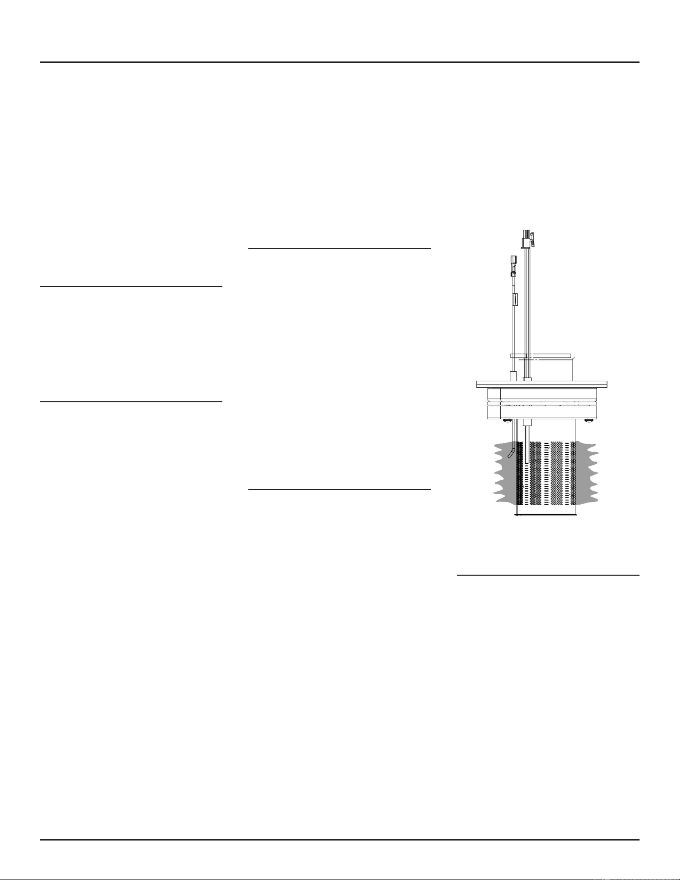
7. Flush the water heater storage tank to
remove sediment and allow the water to
ow unl it runs clean.
8. Close the water heater drain valve when
ushing is completed.
9. Remove the drain hose.
10. Fill the water heater. See Filling the Water
Heater (page 45).
11. Reconnect the water heater to the
electrical supply to place the water
heater back in operaon.
12. Allow the water heater to complete
several heang cycles to ensure it is
operang properly.
SEDIMENT REMOVAL
Waterborne impuries consist of the parcles
of soil and sand which sele out and form a
layer of sediment on the boom of the tank.
For convenience, sediment removal and lime
scale removal should be performed at the
same me.
Lime Scale Removal
When water is heated dissolved minerals in
the water such as calcium and magnesium
carbonate (lime scale) become less soluble.
As the water temperature rises these minerals
will precipitate or “fall out” of soluon.
The amount of lime scale released from water
is in direct proporon to water temperature
and usage. The higher the water temperature
or water usage, the more lime deposits are
dropped out of the water.
Water hardness also affects lime scale
accumulation. With the temperature and
usage being the same, hard water will release
more lime scale than soer water.
Lime scale reduces heating efficiency as it
accumulates inside a water heater. Heang
transfer surfaces become coated with lime
scale deposits which increases fuel costs to
operate the water heater. Lime scale deposits
can also cause rumbling and pounding noises
as air molecules trapped in the lime scale
escape when heated. Lime scale accumulaon
also reduces the life span of water heaters. For
these reasons a regular schedule for deliming
should be set up.
The depth of lime accumulaon in the boom
of the water heater should be measured
periodically. Inspect by removing the cleanout
cover once every 6 months at rst. Deliming
maintenance should then be performed
based on the me it takes for 1 inch (2.5 cm)
of lime to accumulate in the boom of the
water heater.
Chemical Lime Scale Removal
To dissolve and remove more stubborn lime
scale deposits, UN-LIME® Professional Delimer
should be used.
UN-LIME
®
Professional Delimer is an easy to
handle patented food grade acid formulated
specically for lime scale removal from all
types of water using equipment. Hydrochloric
base acids must not be used to delime the
water heaters covered in this manual.
Follow the instrucons on the UN-LIME
®
to
delime the water heater.
Note: Contact Technical Support for
assistance in ordering the UN-LIME
®
Professional Delimer.
BURNER OPERATION AND
INSPECTION
At least once a year a visual inspecon should
be made of the main burner and the hot
surface igniter assembly for proper flame
characteriscs and ignion sequences. This
can be done by removing the outer plasc
cover. See Figure 58 (page 51).
The main burner should provide complete
combustion of gas, ignite rapidly, give
reasonably quiet operation, and cause no
excessive flame lifting from the burner
ports. If the proper flame characteristics
are not evident, make sure that the ow of
combuson and venlaon air is not blocked.
Inspecon of exhaust/air intake terminaon is
needed to ensure there is no blockage there.
You should also check for soong. Soot is not
normal and will impair proper combuson. A
visual inspecon of the main burner and hot
surface igniter should also be done at least
once a year. See Figure 58 (page 51).
Soot build-up indicates a problem that requires
correcon before further use. Turn “OFF” gas
to water heater by unplugging the power cord
and leave o unl repairs are made. Failure to
correct the cause of the soong can result in a
re causing death, serious injury, or property
damage.
Figure 58. Burner-Blower Assembly
COMBUSTION CHAMBER AND BURNER
CLEANING
In the event your burner or burner air openings
require cleaning, Call your service agency to
remove and clean the burner and correct
the problem that required the burner to be
cleaned.
MAINTENANCE
Residenal Condensing Gas Water Heaters • 51
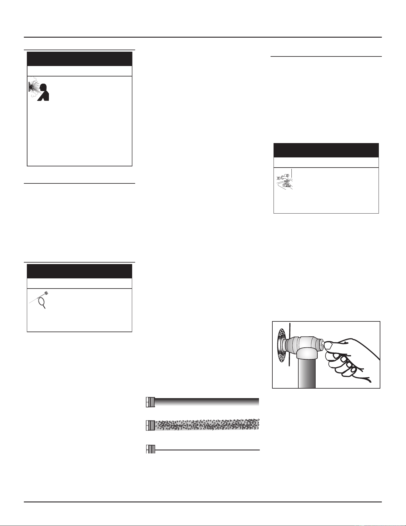
HOUSEKEEPING
Flammable vapors can leak from
their containers and be ignited by
the water heater. The resul�ng fire
and/or explosion can cause serious
injury or death.
Do the following to avoid this hazard:
• Do not place chemical vapor emitting
products near air intake and exhaust
terminations.
• Do not use or store flammable vapor
products, such as gasoline, solvents, or
adhesives in the same room or area near
the water heater or other appliances.
Fire and Explosion Hazard
WARNING
⚠
MAINTAIN MINIMUM CLEARANCES
To ensure sucient venlaon and combuson
air supply, proper clearances from the water
heater must be maintained. See Before you
Begin (page 16). Combusble materials such
as clothing, cleaning materials, or ammable
liquids, etc. must not be placed against or
adjacent to the water heater which can cause
a re.
ANODE ROD MAINTENANCE
A depleted or malfunctioning
anode can lead to damage to the
water heater
Inspect the anode or anodes annually
and replace them as needed.
Property Damage Hazard
⚠
CAUTION
The anode rod is a sacricial metal rod that helps
avoid corrosion and premature failure (leaks) in
the tank. The anode rod is a consumable item.
Inspect the anode rod aer the rst six months
of operaon when you drain and ush the tank.
Replace the anode rod if it is substanally worn
out or depleted. See Figure 59 (page 52).
Thereaer, inspect the anode rod annually or
more frequently if needed. If you use a water
soener, your anode rod will deplete faster than
normal. Inspect the anode rod more frequently,
replacing the anode rod if it is depleted. Once
the anode rod is depleted, the tank will start to
corrode, eventually developing a leak. Obtain
a new anode rod from your local plumbing
supplier or have a qualied person replace it.
(Anode rods are a consumable item and are not
covered under warranty).
Certain water condions will cause a reacon
between the anode rod and the water. The most
common complaint associated with the anode
rod is a “roen egg smell” produced from the
presence of hydrogen sulfide gas dissolved
in the water. The removal of the anode rod
requires a 1-1/16” socket.
Important: Do not operate the water
heater without a funconing
anode rod as this will void any
warranes. A special anode
rod may be available if water
odor or discoloraon occurs.
Note: This rod may reduce but not eliminate
water odor problems. The water supply
system may require special ltraon
equipment from a water condioning
company to successfully eliminate all
water odor problems.
Remove the anode rod for inspecon at least
once per year. To replace the anode:
1. Turn “OFF” the electrical supply to the
water heater.
2. Turn “OFF” the gas supply at the Main
Gas shut-o Valve.
3. CLOSE the cold-water inlet valve to the
water heater.
4. OPEN a nearby hot-water faucet and
leave open to allow for draining.
5. Drain approximately 5 gallons of water
from tank. See Draining and Flushing for
proper procedures. Close drain valve.
6. Remove old anode rod.
7. Use thread-sealer tape or approved pipe
sealant on threads and install new anode
rod.
8. Remove the hose and follow instrucons
in the Filling the Water Heater (page 45).
9. Follow the lighng instrucons on the
label or see Lighting The Water Heater
(page 46) to restart the water heater.
See Figure 2 (page 13) for anode rod locaon.
New Rod
Partially Consumed Rod
Depleted Rod
Figure 59. Anode Rod Depletion
TEMPERATURE-PRESSURE RELIEF VALVE
TEST
It is recommended that the Temperature-
Pressure Relief Valve be checked every 6 months
to ensure that it is in operang condion. When
checking the Temperature-Pressure Relief Valve
operaon, make sure that (1) no one is in front
of or around the outlet of the Temperature-
Pressure Relief Valve discharge line, and (2) that
the water discharge will not cause any property
damage, as the water may be extremely hot.
Use care when operang valve as the valve
may be hot.
The discharge from the
temperature-pressure relief valve
can be hot enough to burn.
Keep your hands clear of the
temperature-pressure relief valve discharge
outlet.
Burn Hazard
⚠
DANGER
To check the temperature-pressure relief valve,
li the lever at the end of the valve several mes
(see Figure 60). The valve should seat properly
and operate freely.
If aer manually operang the valve, it fails
to completely reset and connues to release
water, immediately close the cold water inlet
to the water heater and drain the water
heater. See Draining and Flushing (page 50).
Replace the Temperature-Pressure Relief Valve
with a properly rated/sized new one. See
Temperature-Pressure Relief Valve (page 37)
for instrucons on replacement.
Figure 60. Testing the Temperature-Pressure Relief Valve
If the Temperature-Pressure Relief Valve on the
water heater weeps or discharges periodically,
this may be due to thermal expansion.
Note: Excessive water pressure is the most
common cause of Temperature-
Pressure Relief Valve leakage. Excessive
water system pressure is most oen
caused by “thermal expansion” in a
“closed system.” See Closed Water
Systems and Thermal Expansion (page
36). The Temperature-Pressure Relief
MAINTENANCE
52 • Residenal Condensing Gas Water Heaters
Valve is not intended for the constant
relief of thermal expansion.
Temperature-Pressure Relief Valve leakage due
to pressure build up in a closed system that does
not have a thermal expansion tank installed
is not covered under the limited warranty.
Thermal expansion tanks must be installed on
all closed water systems.
Do not plug the Temperature-Pressure Relief
Valve opening. This can cause property
damage, serious injury or death.
If you do not understand these instrucons or
have any quesons regarding the Temperature-
Pressure Relief Valve call the toll free number
listed on the front page of this manual for
technical assistance.
Without a temperature-pressure
relief valve, the water heater might
overheat or over-pressurize and
explode resul�ng in severe injury
or death.
Do the following to avoid this hazard:
• Install a properly-sized
temperature-pressure relief valve in the
opening provided.
• The temperature-pressure relief valve must
comply with
ANSI Z21.22-CSA 4.4
and the
ASME
code.
Fire and Explosion Hazard
WARNING
⚠
SERVICE
If a condition persists or you are uncertain
about the operaon of the water heater contact
a qualied service technician.
Use this guide to check a leaking water heater.
Many suspected leaks are not leaking tanks.
Oen the source of the water can be found
and corrected.
If you are not thoroughly familiar with gas
codes, your water heater, and safety pracces,
contact your gas supplier or qualied installer
to check the water heater.
Read this manual rst. Then before checking
the water heater make sure the gas supply has
been turned “OFF”, and never turn the gas “ON”
before the tank is completely full of water.
MAINTENANCE
Residenal Condensing Gas Water Heaters • 53
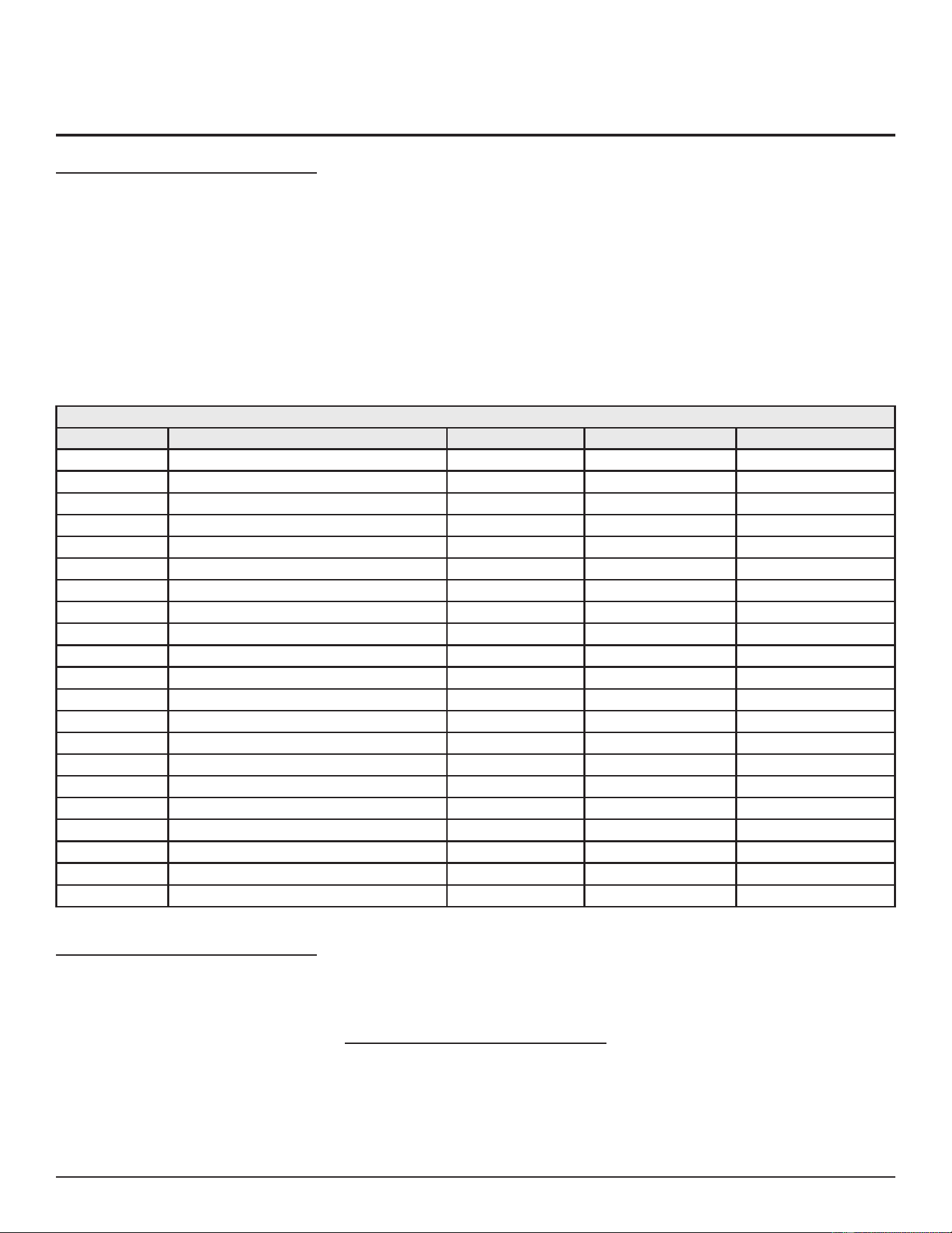
TROUBLESHOOTING
SERVICE MODE
To enter in the service mode, unlock the buons
by simultaneously pressing the “Lock/Unlock”
and “Minus” buons for 3 seconds. In service
mode, the “service” icon shows on the display.
While in service mode, pressing the “Plus/
Minus” (SW3 & SW4) buons cycles between
service codes. The numeric display shows the
service code for 1 second, followed by the
actual measurement, which is displayed for 3
seconds.
Example:
H06-5.00 is the service code for “H06 Blower
RPM target,” and “5.00” is the blower speed
(5.00x1000 = 5,000 rpm).
The display connues to show the service code
and the measurement value unless the up or
down arrow buon is pressed to switch to the
next item.
To exit service mode, simultaneously press
the “Lock/Unlock” (SW2) and “Minus” (SW4)
buons again for 3 seconds. Also, if in service
mode and no buon is pressed for 30 seconds,
the unit will go back to operaon mode, with
the setpoint on the display and the buons
locked.
Table 20. Service Code Functions
Service Code Service Functions Range Unit On LCD
H01 SW code / SW revision
H01_xxx_xxx
H02 Tank temperature 0-999 °C /°F
H02_xxx
H03 Tank temperature 2 0-999 °C /°F
H03_xxx
H04 Flame current 0-9.9 uA
H04_xx
H05 Blower rpm (actual) 1.00-9.99 (x1000) rpm
H05_xxx
H06 Blower rpm (commanded) 1.00-9.99 (x1000) rpm
H06_xxx
H07 LDM Voltage 0.00-9.99 V
H07_xxx
H08 Total Heang cycles 0-999999 -
H08_xxx_xxx
H09 Total heang me 0-999999 h
H09_xxx_xxx
H10 Total Ignion failures 0-999999 -
H10_xxx_xxx
H11 Total Flame loss failures 0-999999 -
H11_xxx_xxx
H12 Error code History 1 - -
H12_xxx_xxx
H13 Error code History 2 - -
H13_xxx_xxx
H14 Error code History 3 - -
H14_xxx_xxx
H15 Error code history 4 - -
H15_xxx_xxx
H16 Error code History 5 - -
H16_xxx_xxx
H17 Error code History 6 - -
H17_xxx_xxx
H18 Error code History 7 - -
H18_xxx_xxx
H19 Error code History 8 -
H19_xxx_xxx
H20 Error code History 9 - -
H20_xxx_xxx
H21 Error code History 10 - -
H21_xxx_xxx
OUTLET AIR PRESSURE SWITCH (OAPS)
The role of the OAPS is to detect a blocked ue
outlet (blocked vent). It is a normally closed
switch that opens when the outlet vent is
parally or totally blocked. In case it opens, the
heater ceases heang mode, goes to post-purge
and displays E06. Once the post-purge is over,
if heat request is sll present and the OAPS is
closed, the system should restart and aempt
to start a new heang cycle. If the OAPS opens
three mes in less than 60 minutes since rst
occurrence the heater ceases heang mode,
goes to post-purge, and displays E05. See
Clearing Error Codes (page 56).
INTAKE AIR PRESSURE SWITCH (IAPS)
The role of the IAPS is to detect a blocked air
inlet. It’s a normally closed switch that opens
when the inlet vent is partially or totally
blocked. In case it opens, the heater ceases
heang mode, goes to post-purge and displays
E23. Once the post-purge is over, if heat request
is sll present and the IAPS is closed, the system
should restart and attempt to start a new
heang cycle. If the IAPS opens three mes in
less than 60 minutes since rst occurrence the
heater ceases heang mode, goes to post-purge
and displays E22. See Clearing Error Codes
(page 56).
54 • Residential Condensing Gas Water Heaters
BASIC SEQUENCE OF OPERATION
Call for Heat:
The control determines that a call for heat
is necessary when the water temperature
drops below setpoint minus the dierenal
temperature. The call for heat is ended when
the water temperature rises above setpoint.
When there is no call for heat, the heater
remains in standby mode.
A call for heat is determined by the following
condions:
• If tank temperature < Operang Setpoint
– Dierenal, a call for heat is iniated.
• If tank temperature > Operang Setpoint,
a call for heat is ended.
The tank temperature is the water temperature
measured by the dual thermistor temperature
probe.
The Setpoint is the intended temperature of
the outlet water set by end user and displayed
on LCD display.
Monitor Flame Current
When the heater is in pre-purge, warm-up
or post-purge and the control senses a ame
current, the heater will go in error mode E01
(Flame detected when it is not expected); the
blower will operate at high speed unl the ame
current is not sensed anymore. 15 minutes aer
the disappearance of the ame, the control
will operate normally. When the heater is in
operaon (burner is “on”) and the ame is lost,
aer the post-purge sequence the heater will
iniate a new heang cycle. If the ame is lost
for 3 mes in less than ve minutes the heater
will go in error mode (E03 lose ame 3 mes in 5
minutes). See Clearing Error Codes (page 56).
Burner Ignition Sequence
At power up, the control board, performs
an inter-purge to clean-up the combustion
chamber. Aer this, when call for heat is not
present, the heater is in STAND-BY status.
Aer receiving a call for heat, prior pre-purge
stage, the control will check for the inlet air
pressure switch and outlet air pressure switch
to be closed and no ame signal presence. The
blower will start to operate in pre-purge stage.
At the end of the pre-purge period the HSI
will be energized. Aer 12 seconds (warm up
me), the HSI reaches the ignion temperature;
the gas valve will be energized (open) for the
duraon for 5 seconds (safety me), then the
presence of the ame signal will be veried
by the control. The heating mode will be
maintained unl the call for heat is sased
(tank temperature reaches the Setpoint). The
gas valve will be turned o (closed) and the
blower will operate for the duraon of post-
purge then it will be turned o. The heater
will remain in standby unl a new call for heat
occurs.
WATER LEAK DETECTION
Inially the control will have the leak detecon
funcon disabled by default. In this case the
Leak Detecon Module (LDM) associated errors
E10, E11, and buzzer, are disabled as well.
As soon as an Leak Detecon Module (LDM) is
connected to the control, the Leak Detecon
Funcon is automacally enabled. Errors E10,
E11, and buzzer will be enabled as well. With
the LDM connected, if the voltage at the LDM
input falls below 1.45 V a “Water leak detected”
alarm will be in place (E10 and Buzzer beeping
connuously). This alarm will cease if the LDM
input voltage rises above 1.55 V (leak condion
ceased). Also when the owner acknowledges
the event, he/she can silence the buzzer for 5
minutes by pushing the
button for 3
seconds. Aer 5 minutes, if the leak condion
is sll in place (LDM voltage < 1.45 V) the buzzer
will start beeping connuously. A new push on
the buon will silence the buzzer again for
5 minutes and so on. Once connected, if the
LDM gets disconnected, the error E11 warning
shall be in place (to let the owner know that
the LDM funcon it is not operaonal). If for
any reason the LDM should be unplugged on
purpose, the LDM function and associated
errors can be disabled by pressing the
buon for 5 seconds. It will remain disabled
unl an LDM module is connected again.
Table 21. Water Leak Detection Indications
Status Voltage
Leak detected < 1.45
Leak recover > 1.55
LDM present < 1.8
LDM unplugged > 2
Vdc 3.3
TROUBLESHOOTING
Residenal Condensing Gas Water Heaters • 55
CLEARING ERROR CODES
Hard Faults and Soft Faults can be cleared
following two steps:
1. Unlock the control (by pressing the
buon for 3 seconds), if the interface is
locked
2. Press the and buons
simultaneously for 3 seconds.
So faults are also automacally cleared aer
15 minutes aer the fault condion occurred,
if the condions of the faults disappeared. If
the fault condion is sll set, the control will
aempt to clear the So Faults aer another
15 minutes (and so on).
Auto Reset faults are cleared automacally
when the fault condion disappears.
Table 22. Error Codes
Code Fault description Meaning Error type Clear/Exit
E00 ECO (Dhw High-Limit) T > Tmax 201°F Hard Fault, Buzzer beeping once per
second
Manual Acon
E01 Flame out of sequence Flame detected when it is not expected So Fault Reset in 15 minutes / Manual
acon
E02 Repeated Flame Loss Lost ame 3 mes in 5 minutes So Fault Reset in 15 minutes / Manual
acon
E03 Ignion failure Failed to ignite “n” mes in a row. (“n” is
congurable for development only. It can be 1,
2, 3, 4, or 5)
So Fault Reset in 15 minutes / Manual
acon
E05 Blocked ue Outlet Air Pressure SW open 3rd me in less
than one hour
So Fault Reset in 15 minutes / Manual
acon
E06 Blocked ue Outlet Air Pressure SW open, 1st and 2nd me Auto Reset Fault Aer post-purge
E07 Tank Temperature Probe
(NTC) failure
Tank Temperature Probe (NTC) open or short
or sensed temperature dierence > 4°C
Auto Reset Fault When condion corrected
E10 Water leak detected Vdc < 1.45 Warning, Buzzer beeping connu-
ously
When Vdc > 1.55
E11 LDM open Vdc > 2 V Warning, Buzzer beeping once per
second
When Vdc < 1.8 V, or long press
on “Minus”
E19 Missing short circuit be-
tween X6.6 and X6.12
Missing short circuit between X6.6 and X6.12 Hard Fault, Buzzer beeping once per
second
Manual Acon
E20 Blower not running Blower speed < 200 rpm when blower pow-
ered
Hard Fault, Buzzer beeping once per
second
Manual Acon
E21 Blower speed error Read speed not within +/- 10% of the Set
speed for more than 10 seconds
So fault 3 mes / Then Hard Fault Reset in 15 minutes / Manual
Acon
E22 Blocked air inlet Inlet Air Pressure SW open 3rd me in less
than one hour
So Fault Reset in 15 minutes / Manual
Acon
E23 Blocked air inlet Inlet Air Pressure SW open, 1st and 2nd me Auto Reset Fault Aer venlaon as long as
post-purge
TROUBLESHOOTING
56 • Residenal Condensing Gas Water Heaters
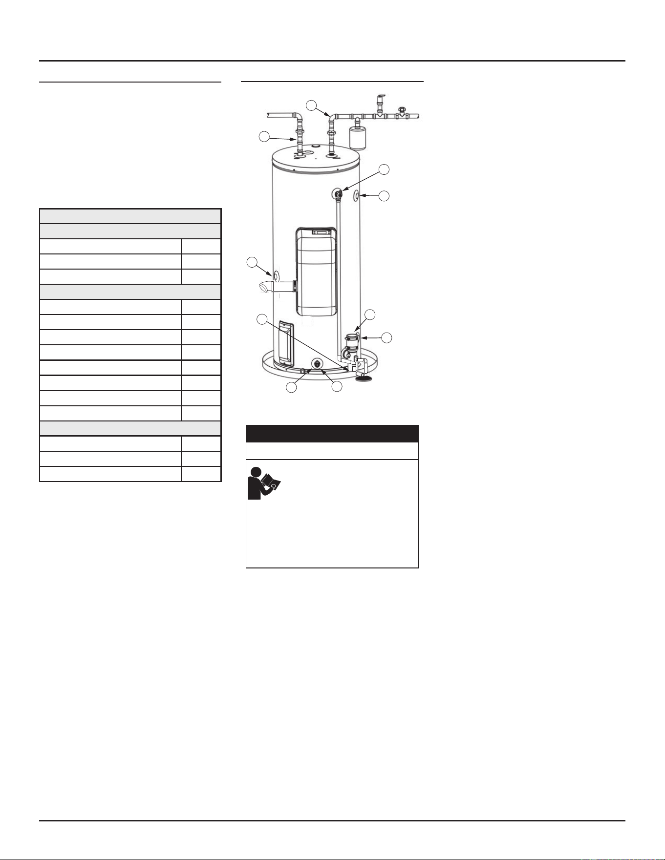
Error Priority
If mulple error condions arise at the same
me, the Control will always give priority to
hard faults over so faults, and to so faults
over warnings, in ascending “class” priority
sequence.
In case of mulple errors of the same “class”
(for example 2 or more hard faults) at the same
me, the Control uses the following priority
table (higher priority rst).
Table 23. Error Priority
Hard Faults
ECO error, T > Tmax (201F) E00
Blower Speed error E21
Blower not running E20
Soft Faults
Blower Speed Error E21
Flame out of Sequence E01
Repeated Flame Loss E02
Ignion Failure E03
Blocked Flue 3rd E05
Blocked Flue, 1st, 2nd E06
Blocked air inlet, 1st, 2nd E22
Blocked air inlet 3rd E23
Auto reset / Warnings
NTC failure
E07
Water Leak detected
E10
LDM open
E11
If there are mulple error condions at the
same time, and at least one requires the
buzzer, the buzzer will sound independent of
the priority.
CHECKING FOR LEAKS
A
B
D
G
G
F
E
C
H
I
Figure 61. Leak Test Locations
Improper installa�on, opera�on,
altera�on, or service might cause a
malfunc�on that results in property
damage, personal injury, or death.
Read and understand this instruc�on
manual and the safety messages
before installing, opera�ng, or
servicing this water heater.
This manual must remain with the
water heater.
Safety Hazard
WARNING
⚠
Never use this water heater unless it is
completely lled with water. To prevent damage
to the tank, the tank must be lled with water.
Water must ow from the hot water faucet
before turning “ON” gas to the water heater.
A. *Condensation may be seen on the hot
water outlet pipe in humid weather or the
hot water outlet connecon may be leaking.
B. *Condensaon may be seen on the cold
water inlet pipe in humid weather or the
cold water inlet connecon may be leaking.
C. Small amounts of water from temperature-
pressure relief valve may be due to thermal
expansion or high water pressure in your
area.
D. *The temperature-pressure relief valve may
be leaking at the tank ng.
E. Water from a drain valve may be due to the
valve being slightly opened.
F. *The drain valve may be leaking at the tank
ng.
G. Leakage from recirculation plug or pipe
connecon.
H. Leakage from the temperature probe
connecon.
I. Condensate from the exhaust connecon.
Leakage from other water heaters, water lines,
or ground seepage should also be checked.
* To check where threaded poron enters tank,
insert coon swab between jacket opening and
ng. If coon is wet, follow the instrucons in
Draining the Storage Tank (page 50) and then
remove the ng. Put pipe dope or thread-
sealer tape on the threads and replace. Then
follow the instrucons in Filling the Water Heater
(page 45).
TROUBLESHOOTING
Residenal Condensing Gas Water Heaters • 57
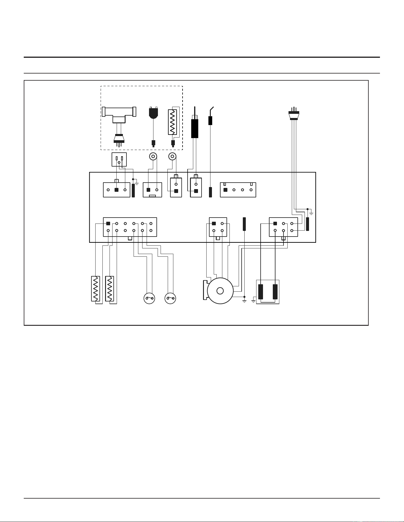
DIAGRAMS
WIRING DIAGRAM
NTC1 NTC2 OAPS Gas ValvesBlower
Flame
Rod
Hall Sensor
PWM
GND (0Vdc)
24Vdc
AC Power
120 VacHSILDM
Water
Shutoff Valve
Outdoor
Temp
Sensor
FA5
X6
X10X7X3
X4 X2
X1
FA1
FA2
FA3
(Optional - External)
1 2 3 4
87
6 1 2
43
1 2 1 2 3 4
1
2
1
2
321
5
4
6
321
Diagnostic Port
L
N
L
N
5
9 10
IAPS
1211
Figure 62. Wiring Diagram
58 • Residential Condensing Gas Water Heaters
SERVICE PARTS LIST
Table 24. Service Parts List
Kit Number Description
100344160 K,SIT BLOWER/GAS CONTROL VALVE,NG,0480.408 (Natural Gas Models Only)
100344191 K, IGNITER SIDEFIRE
100344192 K,FLAME SENSOR BENT
100344193 K,BURNER,4.5",STAINLESS STEEL,NG (Natural Gas Models Only)
100344194 K,GASKET,BURNER,1/2" THK
100368397 K,CONTROL BOARD,NG,50K (Natural Gas Models Only)
100368398 K,CONTROL BOARD,NG,65K (Natural Gas Models Only)
100344198 K,SWITCH, PRESSURE N.C, AIR INTAKE, -1.88" (Natural Gas Models Only)
100344199 K, SWITCH, PRESSURE N.C, FLUE,1.8" (Natural Gas Models Only)
100344200 K,THERMISTOR,3/4NPT
100344201 K,TRAP,CONDENSATE,POLYPROPYLENE
100344202 K,DIPTUBE,HT2,3/4NPTX3X34,PEX (40 Gal Models)
100344203 K,DIPTUBE,HT2,3/4NPTX3X46,PEX (50 Gal Models)
100300397 K,SEC ANODE OUTLET-16" -.80 DIA-5"NIP-MG (40/50 Gal Models)
100108660 K,ANODE-32"-3/4"NPT-.84DIA-MAGNESIUM (40 Gal Model)
100109223 K,ANODE-44"-3/4"NPT-.84DIA-MAGNESIUM (50 Gal Model)
100324744 K,POWERED ANODE, RES-LG,PROD PRES (OPTIONAL)
100346478 K,LEAK DETECTION
100368395 K,SIT BLOWER/GAS CONTROL VALVE,LP,0480.421 (LP Gas Models Only)
100368396 K,BURNER,4.5”,FIBER COATED,LP (LP Gas Models Only)
100368399 K,CONTROL BOARD,LP,50K,CONFIGURED,SER121 (LP Gas Models Only)
100368400 K,CONTROL BOARD,LP,65K,CONFIGURED,SER121 (LP Gas Models Only)
100368411 K,SWITCH, PRESSURE N.C, AIR INTAKE, -1.62” (LP Gas Models Only)
100368412 K,SWITCH, PRESSURE N.C, FLUE, 1.43” (LP Gas Models Only)
100112508 K,BACKFLOW PREVENTER (LP Gas Models Only)
Residential Condensing Gas Water Heaters • 59

500 Tennessee Waltz Parkway,
Ashland City, TN 37015
• Technical Support: 800-527-1953
• Parts: 800-433-2545
• Fax: 800-644-9306
www.hotwater.com
Copyright © 2023 A. O. Smith Corporaon. All rights reserved.