
Instruction Manual
DIESEL GENERATOR
DHY18COM-1
WARNING: Read the instructions carefully before use.

CONTENTS
1.
Contents •• • • • • • • • • • • • • • • • • • • • • • • • • • • • • •• • • • • • • • • •• •• • • • • • • • • • • • • • • • • • • • • •• • • • • • • • • • • •• • • • • • • • • • • • • • • • 1
2. eamble • • • • • • • • • • •• • • •• •• •• • • • • • • • • • • • • • • •• •• • • • • •• • • • • • • •• • • • • • • • • • • • • • • • • •• • • • • • • • • • • • • • • • • • • • • • • • 4
2
.
1
.
I
ntroduction
• • • • • • • • •
•
• • • • • • • • • • • • • • • • • • • • • • • • • • • • • • • • • • • • • • • • • • • • • • • • • • • • • • • • • • • • • • • • • • • • • • •
4
2.
1
.
1
G
eneral
recommendation
s
•• •• •• •• •• •• •• ••
•• •• •• •• •• ••
•• •• •• •• •• •• •• •
• •• •• •• •• •• •• •
• ••
4
2.
1
.2. Structu
r e of
the reference
materia
• • • • • • • • • • • •
• • • • • • • • • • • • • •
• • • • • • • • • • • • • •
• • • • • • • • •
• • 5
2.
1
.2.
1 L
e
v
e
l
A • • • • • • •• • • • • •• • • • • • • • •• • • •• • • • •• • • • • • • • • • • •• • • • • • • • • • • •• • • • • • • • • • • •• • • • • • • • •• • 5
2.
1
. 2.2
L
e
v
e
l
B • • • • • • • • • • • • • • • • • • • • • • • • • • • • • • • • • • • • • • • • • • • • • • • • • • • • • • • • • • • • • • • • • • • • • • • • • • • • • • 5
2
.
2. P
ictogr
ams and their
meanings
• • • • • • • • • • • • • •
• • • • • • • • • • • • •
• • • • • • • • • • • • • • • • • •
• • • • • • • • • • • •
6
2.3.
S
afet
y
instructions
and regulations
•
• •
• • • • • • • • • • • • •
•
• • • • • • • • • • •
• • • • • • • • •
• • • • • • • • • • • • • • •
•• 8
2. 3 .
1
G
eneral ad
v
ice
• • • • • • • • • • • • • • • • • • • • • • • • • • • • • • • • • • • • • • • • • • • • • • • • • • • • • • • • • • • • • • • • • • • • • • • • • • • 8
2.3.2
R
is
k
s
re
l
ated to feed
g
as (conce
rns g
as sets
)
• • • • • • • • • ••
• •• • •• • •• • ••• • •
• • • • • •• • • • 1
0
2.3.3
R
is
k
s re
l
ated to exhaust g
ases and fuels
•
• • • • • • • •
•
• • • •
• • •· • • • "· • • • • ·•
• •
•
•
•
• •· • •
•
• 1
0
2.3.4
R
is
k
s related to toxic
products
• • • • • • • • • • • • • •
• • • • • • • • •• • • •
• •• • • • • • • •• • • •
• • • • • • • • • • • ••
11
2.3.
5
R
is
k
of
re, b
u
rns and ex
p
losion
• • • • • • •• • • • • • •
• •• • • • • •• • • • • • •
• •• • • •• • •
•
• • • • • • •• • • ••
11
2.3.
6
R
is
k
s related to e
l
ectrical net
w
orks
••• • •• •• • • • • • • • •• • • •• • • • ••• • • • •• • • •• • • • • • • • •• • ••
1
2
2.3.
7
D
ang
ers presented
by el
ectric cu
rrents (fi
rst aid
)
••• ••• • •• ••• •••
••••••••••••••••••
1
3
2.3.
8
R
is
k
s
related to mo
v
ing
the set
.
.
.
•• • •• • ••• • •• •••
• • • • • • ••• ••• •••
• •• ••• • • • •• • ••
•
.
.
.
• •• 1
3
2.3.
9
R
ecommendation
r the o
p
erator and e
n
v
ironment
••• • •• •• • ••• ••• ••• •• • ••• ••• •••
1
4
3. Instaation ••••
•
•••••••••••••••••••••••••••••••••••••••••••••••••••••••••••••
•
••••• •••••••••••••••••• 16
3.
1
.
U
n
l
o
ading
• • • • • • • • • • • • •• • •• • • • • • • • • • • • •• • • • • • • •• • • • • • • • • • • • • • • • • • • • • • • • • • • • • • • • • • • • • • • • • • • • • • • 16
3 .
1
.
1
Safety during
unloading
• • • • • • • • • • • • •
• • • • • • • • • • • • • •
• • • • • • • • • • • • • • •
• • • • • • • • • • • • • • •
• • • • • •
1
6
3 .
1
.2
E
xam
p
l
e of materia
l
• • • • • • • • • • • • • • • • • • • • • • • • • • • • • • • • • • • • • • • • • • • • • • • • • • • • • • • • • • • • • • • • • •
1
6
3 .
1
.3 Instructions fo
r unloading
•
•
• • • •
•
• • •
• • • • • • • •
•
•
• •
•
•
• • • • • • •
• • • • • • • • • • • • • •
• •
•
• • • •
• • • • •
•
• • 1
6
3.
1
.3.
1
Slings
•••••• ••••••••• ••••••••••••••• ••••••••••••••••••••••••••••••••••••••• ••••••••• 1
6
3.
1
.3.2
F
ork
lift
truc
k
• • • •• • • • • • • • •• • • • • • •• • • • •• • • • • • •• • • • •• • • • • • •• • • • ••• • • • • •• • • • ••• • • • • •• 1
7
3.
2
Handling instructions
••
•
• •
•
•• •
• • •
•
•
•
• • • • •
• • •
•
•
• • •
•
•
•
•
• • • •
•
•
•
•
• •
•
•
•
• •
•
•
•
• •
• •
t •
• • • • • • • • • • • • • 17
3.3
I
nstal
l
ation of fixed sets
• •
•
• • •
•
•
•
• •
•
•
• •
• • • • • •
• •
•
•
• •
• •
•
• • • •
• • • • • • • • • •
•
• • •
•
• •
•
•
•
• •
• • • • • • • • • • 1
9
3.3.
1 P
osition
•••••• •••••• ••••••••••••••• •••••• •••••• ••••••••••••••• ••••••••• ••••••••• •••••••••
2
0
3.3.2 Measurements and
layout
•
•• • • • • • • ••• •• •
•••
•
•• • ••
•
•• • •• • • • ••• •• •
••• • • • • •• ••• • ••
••• • ••
2
0
3. 3. 2.
1
Static requiremen
ts
• • • • • • • • • • • • • • • • • •
• • • • • • • • • • • •
• • • • • • • • • • • • • • • • • •
• • • • • • • • • • • • •
• •
2
0
- 1/42 -

3
.
3
.
2
.
2
D
yn
ami
c
requirement
s
•• • ••• • •• • •• • • •
••• •• • ••• • •• ••• • •
• •• • •• • ••• • • • •• •
• •• • •• •• • •• • 21
3
.
3.2
.
3 C
on
s
tru
c
tion
• •• • • • •• • •• • ••• • •• ••• • • • •• • •• • •• • •••• •• ••• • • • •• • •• • •• • •••• •• • •• • • • •• • •• • 21
3
.
3
.
2
.
4
B
a
s
e of t
he
s
et
• •• ••• ••• •••••• • •• ••• •• • ••• ••• • • • ••• • •• • • • •• • •• • ••• • • • •• • • •• • •• •• • •• •
21
3
.
3
.
2
.
5
O
pening
s
••• •• • •• • ••• •• • •• • •• • •• • ••• ••• •• • ••• ••• •• • •• • ••• •• • • • • • •• • •• ••• ••• ••• •• • • • • 22
3
.
3
.
2
.
6
L
ifting
• •• ••• • •• • • • •• • •• • •• • ••• • •• ••• • • • • • • ••• • •• • • • • • • ••• • • • • • • ••• • •• • • • • • • ••• • • • • • • 22
3
.
3
.
2
.
7
Soundproong
• • • • • • •• • •• • ••• • • • •
•• • •• • • • ••• • •• • • • • • •
••• • • • • • • ••• • •• • • • • • •
••• • • • • • • 22
3
.
3
.
2
.
8 V
enti
la
tion
••• ••• •••••••••••••••••••••••••••••• •••••••••••• ••••••••• •••••• •••••• ••• 23
3
.
3
.
2
.
9
F
uel
••• • • • ••• •• • ••• • •• • •• ••• • • • ••• •• •••• • • • • •• • •• • • • ••• •• • ••• • •• ••• • • • •• • • •• • •• •• • •• • 2
4
3
.
3
.
2
.
1
0
B
urnt g
as ex
hau
s
t
• • • • • • • • • • • • • • •
• • • • • • • • • • • • • • • •
• • • • • • • • • • • • • • •
• • • • • • • • • • • • • • • •
• 2
5
3
.
3
.
2
.
11 E
le
c
tri
c
ity
•• • ••• • • • • • • ••• • •• ••• • •• •• • ••• •• • • • • ••• • •• ••• • • • • • • ••• • •• • • • • • • ••• • • • • • • 28
3
.
3
.
2
.
12 C
oo
l
ing
••••••••
•
••••••••••••••• ••••••••• •••••• •••••••••••••••••• •••••••••••••••
•
•• 2
9
3
.
3
.
2
.
13
Spe
c
i
al arrangements
•• • ••• • • • • •• • •• • •
• ••• ••• ••• • •• • •
• •• • •• • ••• • • • ••
• • •• • •• •• • •• • 3
0
4
. Ins
t
allatio
n
of
m
obil
e
site
s
et
s
• • • •• • • • • • • • •• • •
• • • • • • • • • • • •• • • •• •
• • • • • • • • • • • • •• • • •
• • • • • • • • • • •• 3
1
4
.
1
G
en
e
ral in
f
o
rmati
on
• • • • • • • • • •• • •• • • •• ••• • • • • • • •• • •• • • • • • •• • •• • • • • • • •• • •• • • • • • •• • •• • • • • • • • • • 31
4
.
2
S
p
e
cic arran
g
ement
s
• • • •• • •• • •• • •• • •• •
•• • • • • •• • •• • •• • •• • ••
• •• • • • • • • • • • • • • • • •
• •• • •• • • • • • • • 3
1
5. R
oa
d
trai
l
er
• • • • • • • • • • • • • • • • • • • • • • • • • • • • • • • • • • • • • • • • • • • • • • • • • • • • • • • • • • • • • • • • • • • • • • • • • • • • • • • • • • • • • • • 32
5.
1
T
railer l
i
n
k
a
g
e
• • • • • • • • • • • • • • • • • • • • • • • • • • • • • • • • • • • • • • • • • • • • • • • • • • • • • • • • • • • • • • • • • • • • • • • • • • • • • • 32
5
.
2 C
hec
k
b
e
f
o
re towin
g
• • • • • • • • • .. • • • • • • • • • • • • • • • • • • • • • • • • • • • • • • • • • • • • • • • • • • • • • • • • • • • • • • • • • • • • • 33
5.
3
D
riv
i
n
g
• • • • • • • • • • • • • • • • • • • • • • • • • • • • • • • • • • • • • • • • • • • • • • • • • • • • • • • • • • • • • • • • • • • • • • • • • • • • • • • • • • • • • • • 33
5.
4
Unhitchin
g
the tra
i
ler
• • • • • • • • • • • •
•
• • • • • • • • • • • • • • • • • • • •
• • • • • • • • • • • • • • • •
• • • • • • • • • • • • • • • • • •
• • 33
5.5
ln1p
lemen
tation
f
o
r in
s
tallatio
n
• • • • • • • • • • • • • • •
• • • • • • • • • • • • • •
• • • • • • • • • • • •
• • • • • • • • • • • •
• • • • 34
6.
Instaation of
e
l
e
c
tri
cal g
e
n
e
ti
ng s
et
s in contain
er
s
• • • •• • •• • • • • ••• • • • • • • •• • • • • • •• • • • •• • 3
5
6
.
1
H
an
d
l
i
n
g
,
tran
sp
o
r
t
a
nd posi
t
i
on
in
g
o
f
the container
s
.. • .... •· • ......
•
· •
• •
• •·
•
•·
3
5
6
.
1
.
1
Ha
n
dl
ing in
s
tru
c
tion
s
• • • •
•
•
•
•
•
• • •
•
•
•
•
• • •
•
•
• • • • • •
•
• • •
•
• • • • • • • •
•
• • • • •
•
• • • • • • • •
•
• • •
•
•
•
•
3
5
6
.
1
.
2
T
ra
n
s
port
·•·····
•
· ................
.
..........
.
.
.
..........
.
............
.
...............
3
7
6
.
1
.
3
I
n
s
t
alla
tion
- positioning .
.
.
.
.....
••
•
.
.
. •
••
... •
••
••• ... ••• ... •••
••• ... ••• ••• ••• ...
•
.
.
38
6
.
2 Maintenance • • • • • • • • • • • • • .. • .. • • • • • • • .. • • • • • • • • • • • • • • • • • • • • • • • • • • •
.
. • • .. • • • • • • • • • • • • • • • • • • • • • 40
7. P
re
para
t
ion before erati
ng
t
he
s
et
.
..
•
•
..
.
......
.
.
...
.
.
•
• • •
.....
.
•
•
..
.
•
•• ••• •• • •
.
.
. ••
.
.
• ••
•
4
1
7
.
1 Installation checks • • • • • • • • • • • • • • • • • • • • • • • • • • • • • • • • • • • • • • • • • • • • • .. • • • • .. • • • • .. • .. • .. • • • • • • • 41
7
.
2
.
Connection checks ••• •
.
. •••
.
. • ••• • • • • .. • •• • • • .. • ••• •• • ... • • • • .. • •• • • • ••• .. • ••• .. • • • • ... • .. 41
7.3
Startin
g
the
g
e
neratin
g
set
•• •
..
• •••
.
.
.
•• • •• • .. • ... •••
•• • .. • ••• •• • •• •
••• ... •• • •• • •••
.. • • • •
41
7 .
4
Loa
d
te
st on installa
tion
• • • • • • • • • • • • • •
• • • • • • • • • • • • • •
• • • • • • • • • .. • •
• • • • • • • • • • •
• • • • • • • • • .. • •
•
41
8
.
B
a
tter
y
m
ai
n
te
nanc
e
• • • • • • • • • .. • • • • • • •
.
. • .. • • • • • • • .. • • • • • • • .. • • • • .. • .. • .. • .. • • • • .. • .. • .. • .. • • • • 42
9
.
Declaration of Conformity ..................................................................................................................43
- 2/42 -

Attached documents
User manual for the control unit, tted (level A)
User and maintenance manual for the engine (level A)
User and maintenance manual and spare parts catalogue for the alternator
(level A)
Wiring diagrams (supplied with the reference material or with the electrical generating set)
(Level A)
Engine spare parts catalogue (level B)
- 3/42 -

2. PREALE
2.1. Introduction
2.1.1 General recommendations
Thank you r choosing an electcal generating set from our company.
This manual has been designed to help you operate and maintain your electrical generating set
correctly.
Read the safety instructions carefully in order to prevent any accident, incident or damage.
These instructions must always be llowed.
In order to obtain optimum eiciency and the longest possible life r the electrical generating
sets, maintenance operations must be carried out according to the periods indicated in the
attached preventative maintenance tables.
If the electrical generating set is used under dusty or unfavourable conditions, some of these
periods will be shorter.
Ensure that all adjustments and repairs are caned out by personnel who have received the ap
propriate training. The dealers are suitably qualied and can answer all of your questions.
They can also supply you with spare parts and other services.
The left and right sides can be seen from the back of the electrical generating set
(the radia
tor is at the ont) .
Our electrical generating sets have been designed so that damaged or worn parts can be re
placed by new or reconditioned parts thereby reducing the out of action period to a minimum.
For all parts replacement, contact your nearest dealer representing our company who will
have the necessary equipment and propey trained and informed sta to carry out mainte
nance, parts replacement and even total reconditioning of generating sets.
Contact your local dealer for the availablerepair manuals and to make the necessary arrange
ments for training personnel in implementation and maintenance.
IMPORTANT
Some user manuals and maintenance manuals r the engines fitted to the electrical
generator assemblies include information on the control units and detail the engme
starting and stopping procedures.
As the electric generator assemblies are tted with assembly-specic test and control
panels , only the information in the documentation regarding the panels tted to the as
semblies should be taken into consideration.
- 4/42 -
2.1.2. Structure of the rerence material
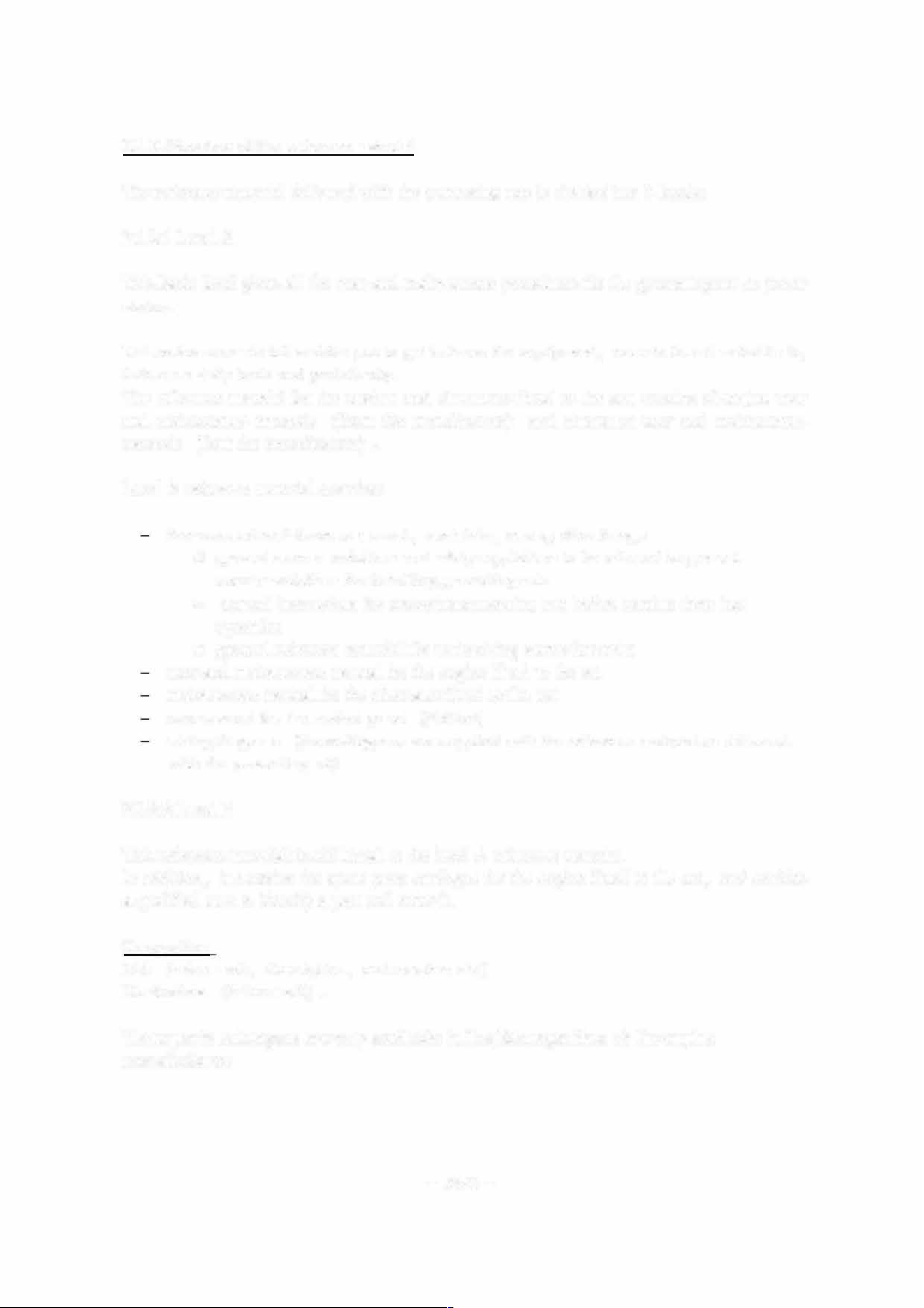
The reference material delivered with the generating sets is divided into 3 levels:
2.1.2.1 Level A
This basic level gives all the user and maintenance procedures r the generating set or power
station.
This reference material enables you to get to know the equipment, operate it and maintain it,
both on a daily basis and periodically.
The reference material r the engines and alteators fitted to the sets consists of engine user
and maintenance manuals ( from the manufacturer) and alternator user and maintenance
manuals (from the manucturer) .
Level A rerence material contains:
the user and maintenance manual, containing among other things:
O general recommendations and safety regulations to be adhered to general
recommendations for installing generating sets
o general instructions r preparing generating sets before putting them into
operation
O general rerence mateal r maintaining starter batteries
user and maintenance manual for the engine fitted to the set
maintenance manual for the alteator tted to the set
user manual r the control panel ( tted)
wiring diagrams (these diagrams are supplied with the reference material or delivered
with the generating set)
2.1.2.2 Level B
This reference material is additional to the level A reference material.
In addition, it contains the spare parts catalogue r the engine tted to the set, and enables
a qualified user to identify a part and order it.
Composition
List (index mark, description, part number etc.)
Illustrations (index mark) .
These parts catalogues are only available in English regardless of the engine
manufacturer.
- 5/42 -
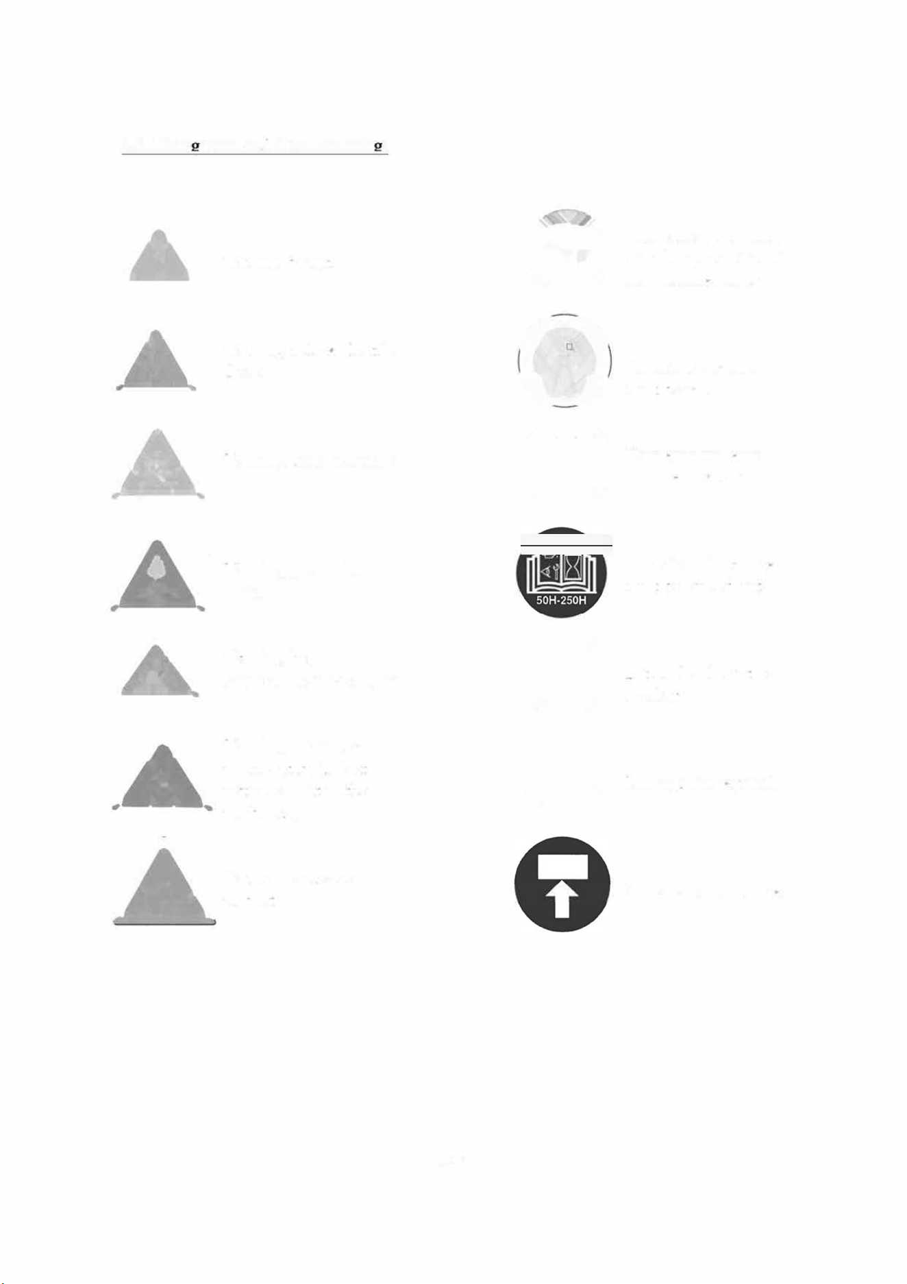
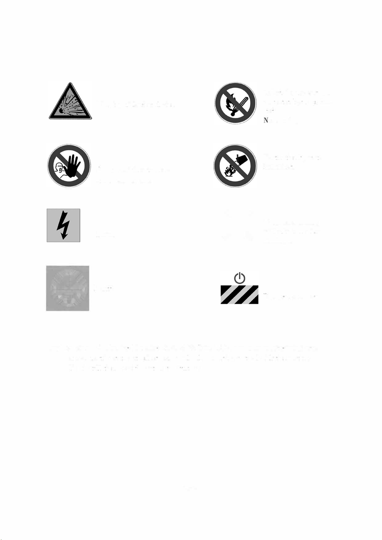
2.2. Picto rams and their meanin s
•
Publications delivered
Waing danger
with the generating set
must be refened to
�
Waing, risk of electric
a
shock
Protective clothing
must be worn
&
Waing, toxic materials
•
Your eyes and ears
must be protected
£
Waing, pressurised
Periodic maintenance
liquids
must be carried out
£
Waing, high
•
temperature, risk of burns
Battery level must be
checked
£
Waing, rotating or
•
moving parts (risk of
getting caught in the
Lifting point required
machinery)
A
Waing, conosive
product
Stacking point required
-6/42 -
•
Waing, risk of explosion
Entry prohibited to non
authoiised persons
Power
• Earth
•
Naked flames and un
protected lights prohib
ited.
o smoking
Exctinction by water
prohibited
\Vhen on a trailer,
eatth the set before
staiting it
Emergency cut-out
Application of EU Machine Directive 98/37 of 22 June 1998 in relation to generating sets.
-
access restricted to authorised personnel only according to he legislation in force
-
live installation: possible automatic start
-
up.
- 7/42 -
2.3. Safety instructions and regulations
THESE SAFETY PRECAUTIONS ARE IMPORTANT
If you do not undetand or have any questions about any point in this manual, contact your
dealer who will explain it to you or give you a demonsttion. A list of ris
k
s and precautionary
measures to ta
k
e llows. You should also refer to any local and national regulations that apply
in accordance with your own jurisdiction.
2.3.1 General advice
Read and understand the manuals provided with the generating set in full.
Do not wear loose clothing and do not go near the machines when opeting. Note that
the ns are not clearly visible when the engine is running.
W am all people present to
k
eep well bac
k
during operation.
The generating set should always be controlled by an experienced person.
Always test the generating set from the control panel.
Follow the maintenance table and its directions.
Never let anyone else use the generating set without having rst given them the
necessary instructions.
Do not run the engine without having retted the protective covers.
Engine with turbocharger: never start the engine without fitting the air lter.The rotating
compressor wheel in the turbocharger can cause severe physical injury.
Foreign objects in the inta
k
e duct can cause mechanical damage.
Engine with air preheating (starter components): never use starter aerosol or similar
product as starter assistance.
When it comes into contact with the starter component, an explosion may occur in the
inlet manifold and lead to physical injury.
Never let a child touch the generating set, even when not in use. Avoid using the
generating set in the presence of animals (can distress the animal).
Never start the engine without an air lter or exhaust.
Always llow current local regulations regarding generating sets and use of el
(petrol and gas) before using your generating set.
Never use sea water or any other electrolitic or corrosive product in the coolant circuit.
- 8/42 -
Disconnect the battery and pneumatic starter (if there is one) bere carrying out any
repair, to prevent the engine from starting accidentally. Fit a panel over the controls to
prevent any attempt at starting.
Do not modify the engine.
Only use the correct techniques r turning the crankshaft to rotate the crankshaft
manually. Do not try to rotate the crankshaft by pulling or exerting rce on the lever
on the n. This method can cause seous physical or material harm or damage the n
blade
(s), leading to premature breakdown of the n.
Always use tools in good condition. Check that you have understood how to use them
bere starting a procedure.
Only t original spare parts.
Use tools that correspond to the work being carried out.
Clean all traces of oil or coolant with a clean cloth.
Never use petrol or other flammable substances to clean parts. Use only approved
cleaning solvents.
Do not use a high-pressure cleaner r cleaning the engme and fittings. The radiator,
hoses, electrical components etc. could be damaged.
Avoid accidental contact with parts that reach high temperatures
( exhaust manild,
exhaust)
Engage the parking brake when the geneting set on its trailer 1s installed on the
operating site.
When setting on a slope; check that no-one is behind the trailer.
Protective eyewear must be worn when handing during maintenance operations.
Operators should remove watches, chains, etc.
- 9/42 -
2.3.2 Risks related to ed gas (concerns gas sets)
WARNING - DANGER
The gas is explosive. It is rbidden to smoke, go near or create sparks when the tank is being
filled and near to the generating set.
Request the user technical notes and LPG or NG safety data sheets from your gas
supplier.
Gas installations must be installed, maintained and repaired by recognised specialists.
-
Do not attempt to open, unseal or intervene in gas supply pressure relief valves and
on the gas line in general.
-
Gas supply procedures must be caied out in fresh air (outside) in accordance with
local regulations, in an area well away om re, people or animals.
2.3.3 Risks related to exhaust gases and els
WARNING -DANGER
generating sets should not be operated in unventilated areas.
Always llow the local regulations in rce regarding generating sets and use of fuel
(petrol, diesel and gas) bere using your generating set.
Fuel lling should be cared out when the engine is stopped (except r sets with an
automatic filling system)
Engine exhaust gases are toxic: Do not operate the generating set m non ventilated
areas. When installed in a ventilated area, the additional requirements r protection
against fire and explosions must be observed.
-
a burnt gas exhaust leaks, the generating set may become more noisy. In order to be
sure of its efficiency, you should periodically examine the burnt gas exhaust.
-
Pipes must be replaced as soon as their condition requires it.
- 10/42 -
2.3.4 Risks related to toxic products
WARNING - DANGER
The corrosion inhibitor contains alkali. This substance should not come into contact with the
eyes. Avoid any prolonged or repeated contact with skin. It should not be swallowed. In the
event of skin contact, wash thoroughly with water and soap. In the event of contact with eyes,
rinse immediately with plenty of water r at least 15 minutes. CALL A DOCTOR IMMEDI
ATELY. KEEP THE PRODUCT OUT OF THE REACH OF CHILDREN.
The anti-rust product is toxic and dangerous if absorbed. A void any contact with skin or eyes.
Read the instructions on the packaging.
Glycol is a toxic product and dangerous if absorbed. A void any contact with skin or eyes.
Read the instructions on the packaging.
- Never expose the equipment to liquid splashes or rainll, and do not place it on wet
ground.
Always use the recommended fuels. Using low quality fuels risks damaging the engme
and altering perfoance
The battery electrolyte is harml to skin and especially eyes. If splashes get into eyes,
rinse immediately with running water and/or a 10% diluted boric acid solution.
Wear protective eyewear and strong base resistant gloves r handling the electrolyte .
2.3.5 Risk of re, burns and explosion
WARNING - DANGER
The engine should not be operated in areas containing explosive products. There is a risk of
sparks rming where all electrical and mechanical components are not shielded.
Beware of creating sparks or ames and do not smoke near batteries as the electrolyte
gases are highly flammable (especially when the battery is being lled). Their acid 1s
also harmful to the skin and particularly the eyes.
Never clean, lubcate or adjust an engine when it 1s m operation ( unless you are
qualied to do so, in which case extreme care must be taken to avoid accidents)
-
Never make adjustments that you are not miliar with.
Never cover the generating set with any material while it 1s working or just after it
stops (wait until the engine has cooled)
Do not touch hot components such as the exhaust pipe and do not put combustible
material on them.
- Keep all flammable or explosive products (petrol, oil, cloth, etc.) well away when the
set is running.
-11/42-
Good ventilation is required r your generating set to work properly. Without
ventilation, the engine will quickly reach an excessive temperature that could lead to
accidents or damage to the equipment and surrounding items.
Do not take off the radiator cap when the engine is hot and the coolant is pressurised
due to risk of bus.
Depressurise the air, oil and coolant circuits, bere removing or disconnecting any
unions, ducts or connected components. Be aware of any possible pressure that might
be present when disconnecting a device from a pressurised system. Do not look r
pressure leaks manually. High pressure oil can cause physical accidents.
Some preservative oils are ammable. Also, some are dangerous to inhale.Check that
ventilation is good. Use a protective mask.
Hot oil causes burns. Avoid contact with hot oil. Check that the system is no longer
pressurised bere caying out any procedures.Never start or run the engine when the
oil filling cap is o as oil may be ejected.
Never start or run the engine when the oil filling cap is o as oil may be ejected.
Never cover the generating set with a ne layer of oil r anti-rust protection.
Never fill up the oil or coolant when the generating set is running or when the engme
is hot.
2.3.6 Risks related to electrical networks
The electcal equipment supplied with the generating set complies with standard
NF C 15.100 or the standards of the relevant countries
Read the manucturer's identification plate carefully. The values r voltage, power,
current and equency are shown. Check that these values match the supply use.
Never accidentally touch naked wires or disconnected connections.
Never handle a generating set with wet hands or feet.
Maintain electrical wires and connections in good condition. Using equipment m poor
condition can lead to electrocution and damage to equipment.
Any procedure on the equipment must be carried out voltage free.
Electrical connections must be made in accordance with current standards and
regulations in the country.
Do not use ulty, poorly insulated or provisionally connected wires.
Do not invert the positive and negative terminals of batteries when connecting them.
Such an inversion can lead to severe damage to the electrical equipment. Follow the
wiring diagram supplied by the manucturer.
- 12/42 -
The generating set should not be connected to any other power sources, such as the
public distribution network. In specic cases where there is a reserve connection to
existing electrical networks, it must only be carried out by a qualified electrician, who
should take the operating differences of the equipment into account, according to
whether the public distribution network or generating set is being used.
Protection against electric shocks is ensured by an assembly of specific equipment. If
this needs to be replaced, it should be by components with identical nominal values
and specications.
Due to strict mechanical specifications you should only use flexible resistant rubber
sleeved wires, in compliance with CEI 245-4 or equivalent wires.
2.3.7 Dangers presented by electric currents
(rst aid)
First aid
In the event of an electric shock, cut off the voltage immediately and activate the set's emergen
cy stop. If the voltage has not yet been cut o, move the victim out of contact with the live con
ductor as quickly as possible. Avoid direct contact both with the live conductor and the victim's
body. Use a d
plank of wood, d
clothes or other non-conductive materials to move the victim
away. The live wire may be cut with an axe. Take extreme care to avoid the electric arc that re
sults from this.
Begin emergency procedures
Resuscitation
If breathing has stopped, begin articial respiration at once in the same place the accident took
place unless the victim or operator's life could be endangered by this.
In the event of cardiac arrest, car out cardiac massage.
2.3.8 Risks related to moving the set
Use lifting units to lift the generating set. Always make sure that the lifting equipment
is in good condition and has a sufficient lifting capacity.
In order to work in complete safety and prevent the components fitted to the top of the
engine om being damaged, the engine should be lifted with an adjustable boom. All
chains and cables should be parallel to one another and as peendicular as possible to
the top of the set.
If other equipment fitted to the generating set alters its centre of gravity, special lifting
devices may be required to maintain the correct balance r working in total safety.
Never carry out work on a generating set that is suspended on a lifting device only.
-13/42-
2.3.9 Recommendation r the operator and environment
Operating personnel should be aware of the safety and operating instructions. These
will be regularly updated.
Operating should be monitored, directly or indirectly, by someone designated by the
operator who is miliar with the installation and dangers and problems regarding
products stored and used in the installation.
No-one from outside the establishment should be able to access the installations eely,
unless designated by the operator.
The user should check the service pressures of the different pressure stages, making
sure that they are in accordance with the prescribed operating requirements. The user
is also responsible r making the apparatus adjustments according to the manucturer's
instructions and should check that the apparatus is operating correctly.
The user should create or obtain a document describing modications and showing
alterations made to the installations in relation to the original document.
Manucturers' notes should be available to technical st, on site if possible.
The inteal network diagram should be displayed as close as possible to the access
points showing all the individual points. Internal and external network inrmation can
be contained in a single distribution diagram.
A sign on the door identies and gives details of the operating company and includes
the telephone number r the gas supplier emergency department.
Personnel should be aware of the layout of the premises and they should be identied
on site to simpli procedures. In the event of a problem, this type of knowledge about
installations is crucial when poor identification of the premises might make a situation
woe.
Written operating instructions must be available for operations that involve dangerous
handling procedures and driving installations. In particular, these instructions
prescribe:
o Operating modes
O Frequency of testing r safety devices and devices r handling pollution and
other harmful substances generated by the installation
O Methods for maintenance , checking and use of adjustment equipment and
safety devices.
The operator should make the necessary arrangements to satisfy site aesthetic
requirements. The whole site must be kept clean and in good condition.
The premises must be kept clean and cleaned regularly with in order to avoid piles of
dangerous or pollutant material or dust that could be susceptible to catching re or
causing an explosion. The cleaning equipment must be adapted to accommodate the
risks presented by such products and dust.
- 14/42 -

The presence of dangerous or combustible mateals on premises where combustion
apparatus is sheltered is limited to what is required for the operation.
The installations must be operated underthe constant supervision of a qualified
person. This person should periodically check that the safety devices are working
properly and ensure the correct el supply to the combustion apparatus.
Apart from combustion apparatus, flames in any rm are prohibited. This should
be displayed in bold on a sign.
Residual water, mud and waste spray is prohibited.
The fuels to be used should correspond to the ones in the declaration file and the
specifications prescribed by the combustion apparatus manucturer.
The el is considered as being in the physical state that is introduced into the
combustion chamber.
Burning waste in the open air is prohibited.
Except for where a specific agreement has been made, once the gas supply mam
unit has been closed, it can only be reopened by the gas distributor. However the
user may conditionally have access to it. Check for each site.
Always protect your hands when detecting leaks. Pressused fluids can enter body
tissues and cause severe harm. Risk of blood poisoning.
Drain and discard engine oil in a designated container
( the fuel distributo can
collect your used oil) .
- 15/42 -
3. INSTTION
WARNING
Sections 3, 4 and 5 contain only general recommendations.
It is recommended that
y
ou use a professional to ensure correct installation and start-up.
The company cannot be held responsible for breakdowns related to the conditions of
installation.
3.1. Unloadin
3 .1.1 Safet
y
during unloading
In order to unload generating sets om their transport mountings, under optimum conditions of
safety and efficiency, you should check that the following points are being followed
correctly.
- Suitable lifting vehicles or equipment for the work.
- Slings positioned in the rings provided for this procedure or lifting arms resting fully
undeeath the ame cross beams.
- Suitable ground to accommodate the load of the set and liftin
g
vehicle, without strain
(if not, put down sufficiently strong and stable boards) .
Remove the set as close as possible o its place of use or transport, in a clear space with free
access.
3.1.2 Exam
p
le of material
- crane, slings, lifting beam, safety hook, shackles.
-
fork lift tck.
3.1.3 Instructions for unloading
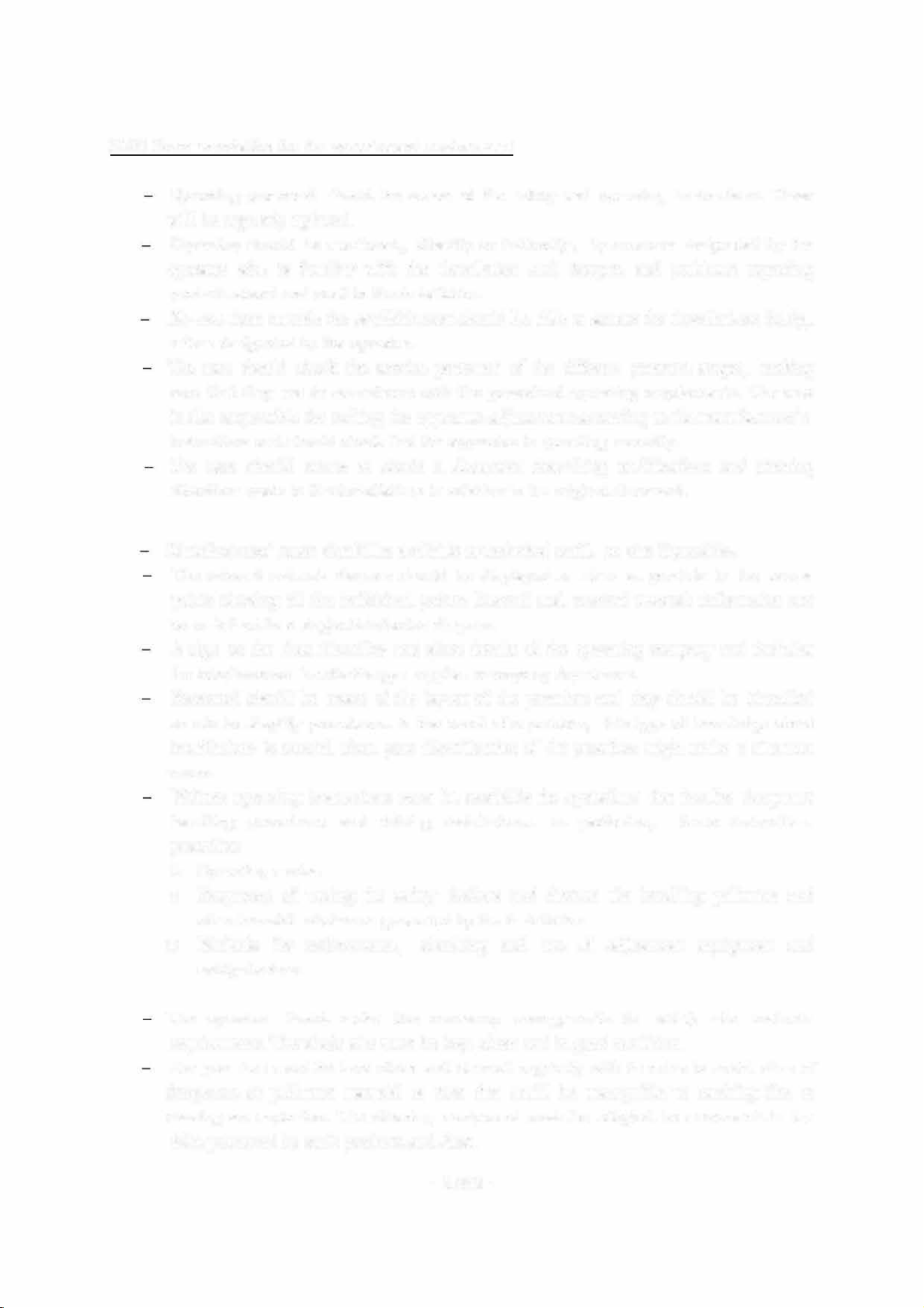
3.1.3.1 Slings
-
attach the lifting vehicle slings to the rings on the generating set designed for this procedure.
- hang the slings carelly.
- check that the slings are correctly attached and the equipment is solid.
- Lift the generating set carefully.
- direct and stabilise the set towards the chosen position.
- carefully set down the equipment while continuing to position it.
- release the slings, then detach and remove the lifting rings.
Warning: The slings must be perpendicular to the f
r
ame
in order not to interfere with the set
(no rubbing) .
- 16/42 -
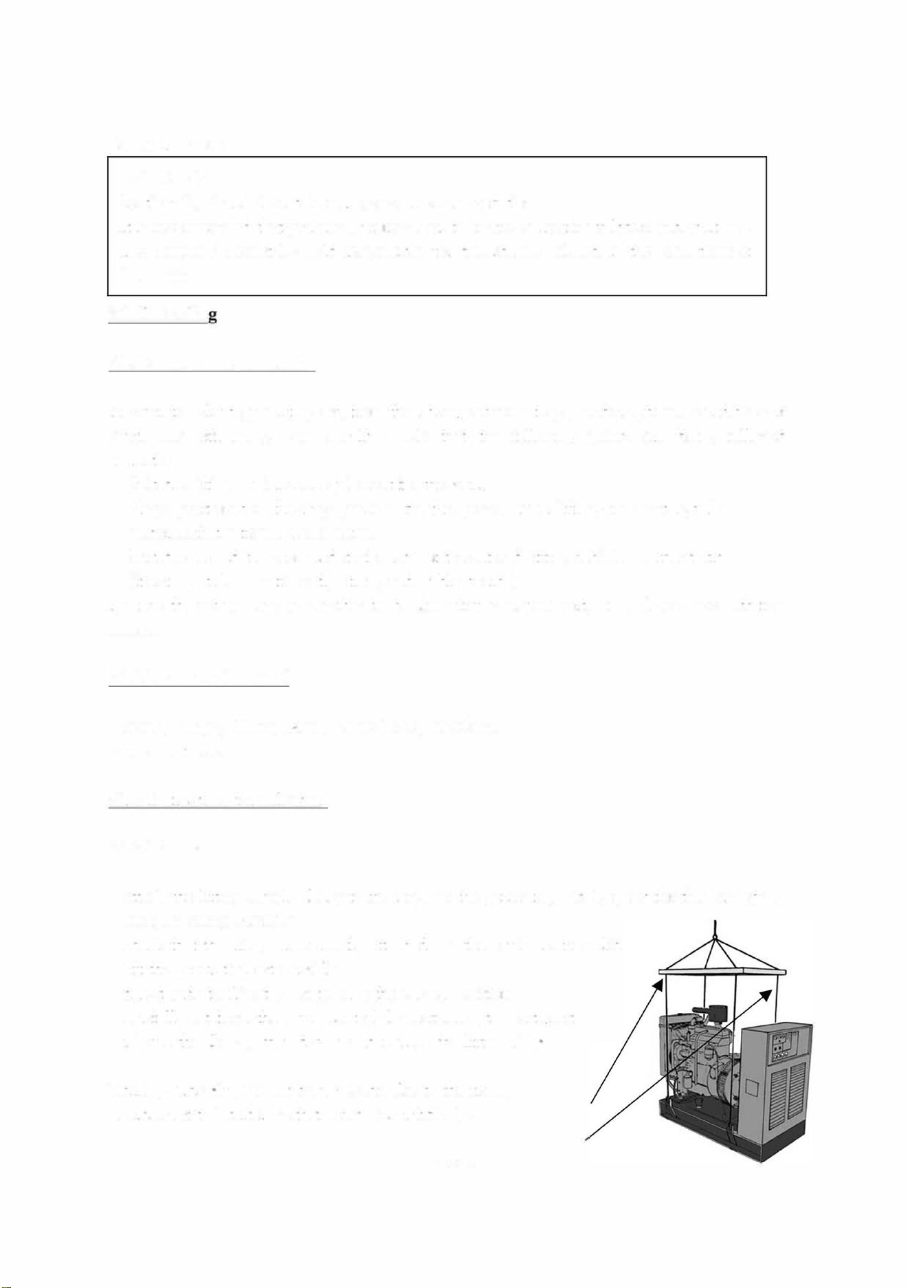
3.1.3.2 Fork lift tmck
- position the arms of the fork lift under the frame, making sure that only the cross beams are
resting on the arms.
- lif and handle the equipment carefully.
- set down the generating set in its unloading position.
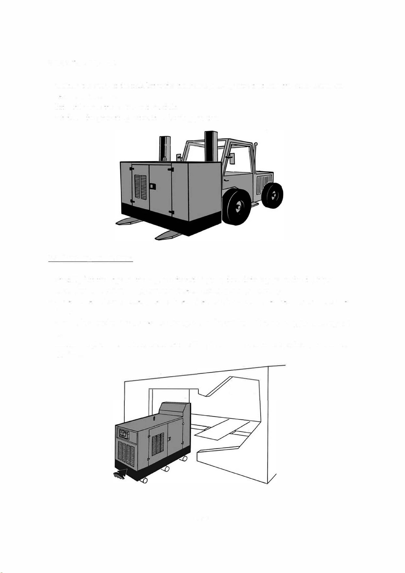
3.2 Handling instructions
- carefully lift the edge on the engine side with 2 jacks then slide 3 pipes under the f
r
ame.
- leave the ame under the pipes then move the set by pushing manually.
- while the set is being moved, use the freed pipes by sliding them one after another under the
frame.
- when it has reached the desired location, position the set then lift it up using jacks to suppoit
it.
- remove the pipes and put down the set checking that it is in the correct position, then remove
the jacks.
I
- 17/42 -
It is recommended to use a rk lift h·uck with arms that are longer than the width of the f
r
ame
If you are using a rail or crab once it is in position, continue in the same way as described in
h " 1· "
h
t e s mgs paragrap
- 18/42 -
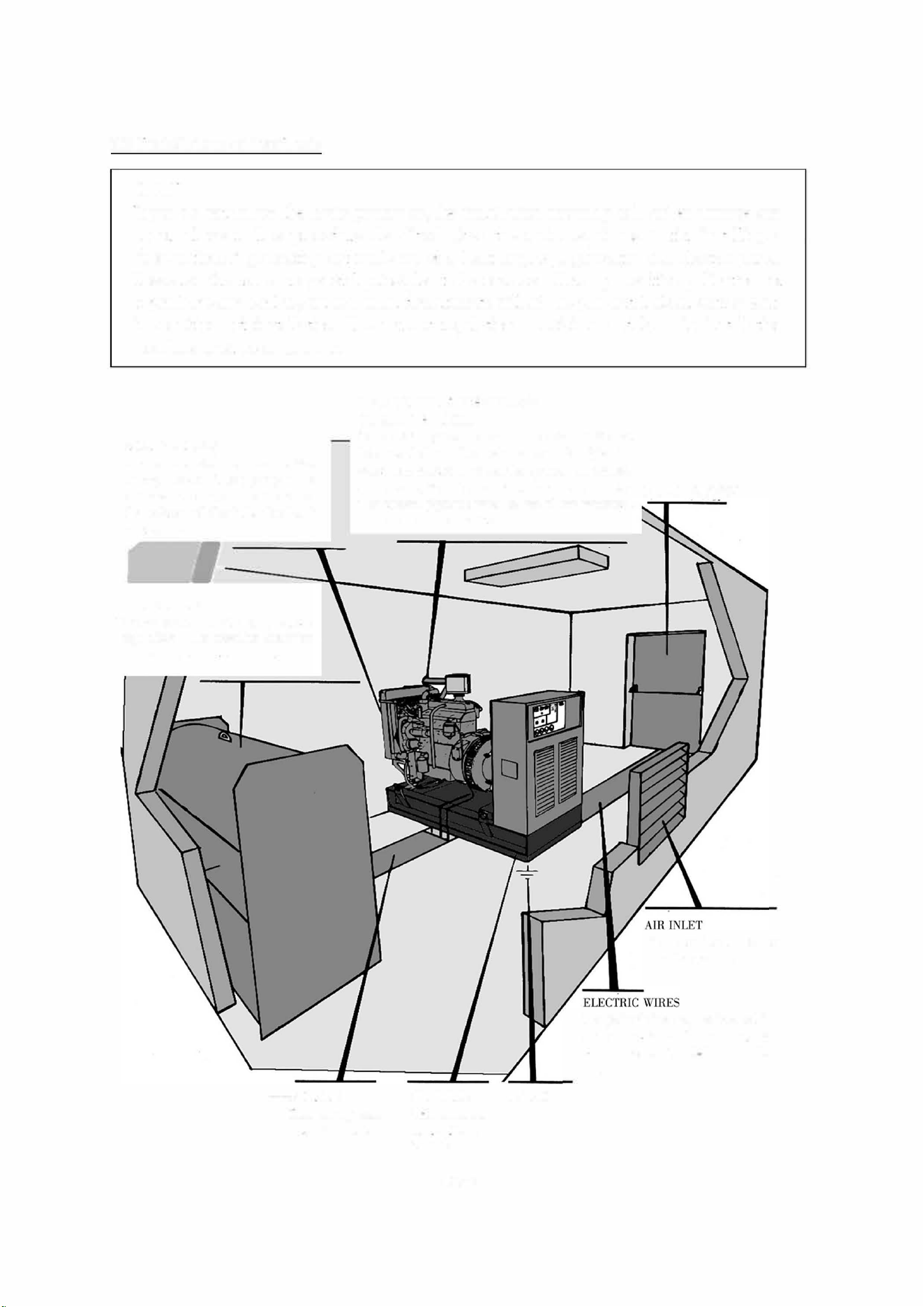
3.3 Installation of fixed sets
NOTE
H you do not follow the basic principles, the installation assembly will suffer damage and
abnormal wear. The procedure described gives the main requirements for installing a
"conventional" generating set made up of a heat engine,a generator and electric panel.
These requirements are general principles to be observed. For any specific applications or
if
you have any doubts, our technical departments will advise you and look at your specif
ic conditions of installation. The current regulations, provisions and laws in installation
locations must be adhered to.
AIR EMISSIONS
Air is evacuated by the radiator
through 1he wall. The opening in 1he
wall should correspond to the size of
the radiator and should be 1ted with
a rain grille.
·( D
FUEL STORAGE
Storage should comply with cwTent
regulations. The retention container
ea n be made of steel or mason,r
FL PIPES
EVACUATION OF EXHAUST GASES
OUTSIDE THE ROOM
If the miginal pipework needs to be e.xtended, it must
be suspended and fit.led with an expansion joint in
serted between the pipes and the silencer (or engine).
In any case, it must not rest on the wall or silencer.
FIREPROOF DOOR
The exhaust pipework must be free of any movement
through the walls or partition
EARTH
Air inlet g,·ille on the door
or on the masomJ.
The path of wires may be i nsta lied in
ducts or aeiially. In this case, the
wires must be installed in a cable
tray
Fuel supply and
retu in a duct
SECURING
THE UNIT TO
THE FLOOR
PLATE
- 19/42 -
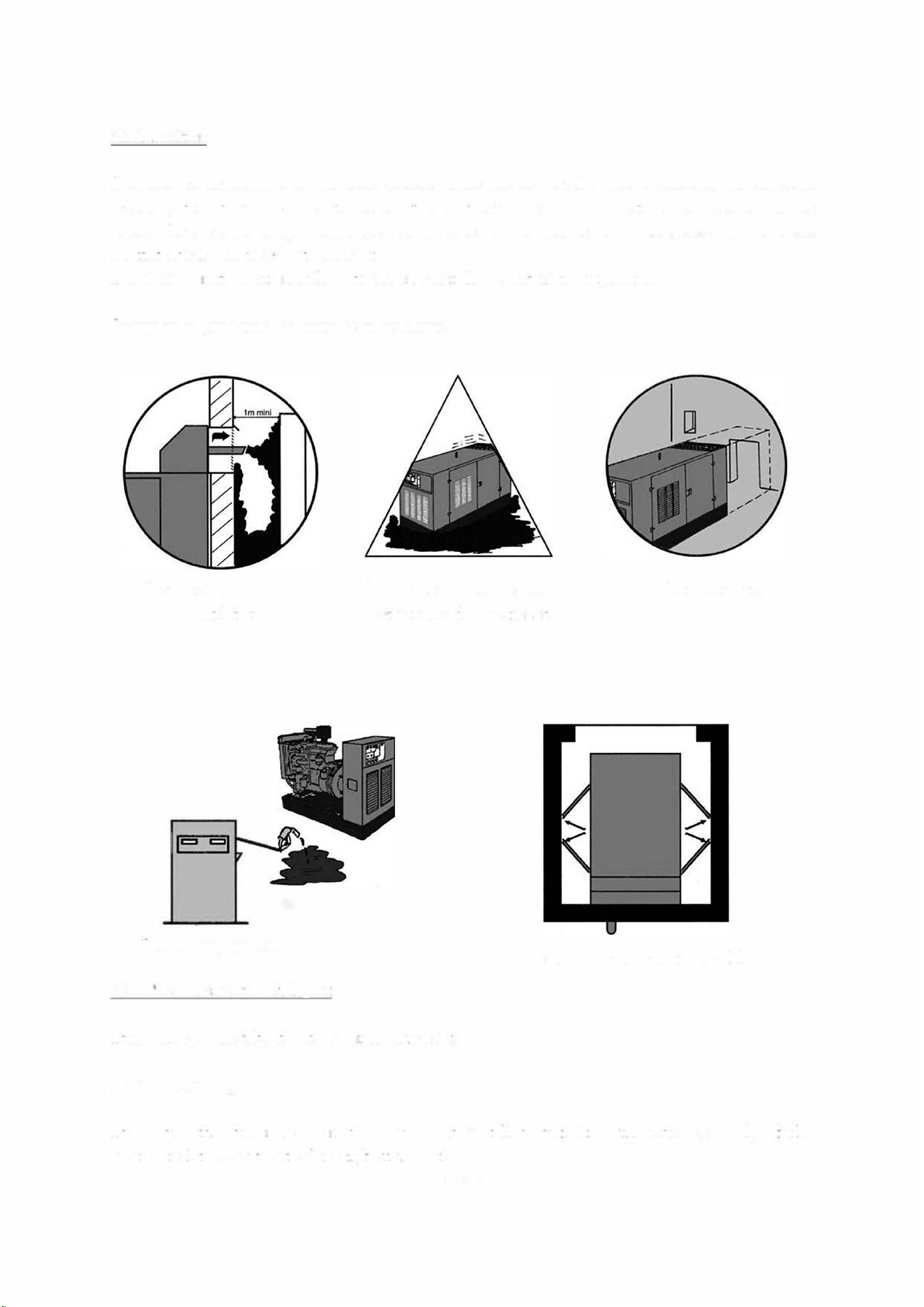
3.3. l Position
It should be determined on the basis of use. There are no specific rules goveing the choice of
location, other than proximity to the electric distribution panel and disturbances caused by the
noise. However, fuel supply, burnt gas evacuation, and the direction of these gases and the noises
emitted should be taken into account.
The choice of its position will be based on carefully considered compromise!
Examples of problems that may be encountered:
Incorrect exhaust and
ventilation
Ground too uneven or soft.
Set incorrectly positioned
Reduced access
Fuel filling impossible
3.3.2 Measurements and layout
Opening cover doors impossible
These are goveed by two types of requirement:
3.3.2.1 Static requirements
These are the dimensions of the equipment installed and its surroundings,namely: daily
service fuel tank, cabinet, silencer, batteries etc.
- 20/42 -
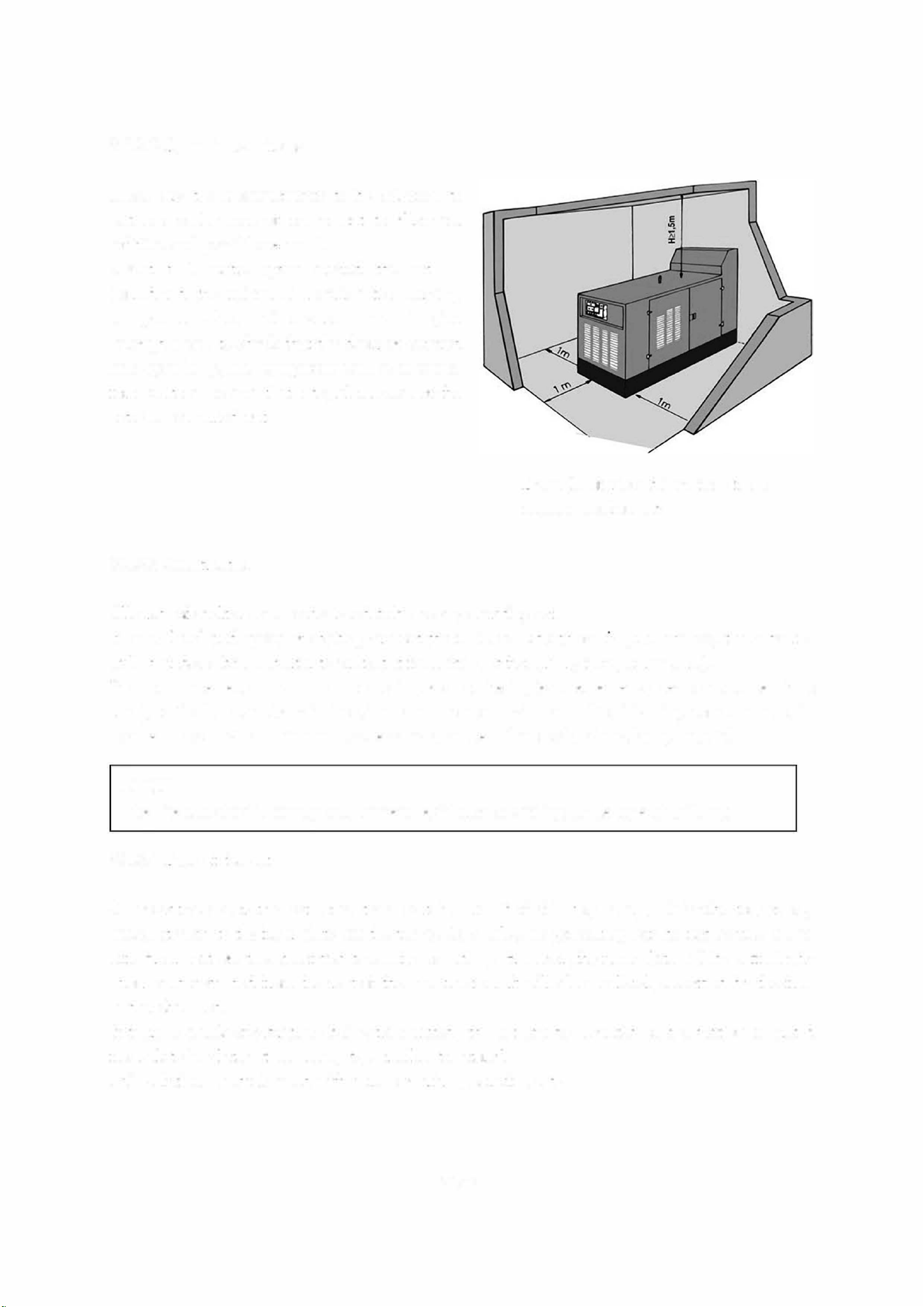
3.3.2.2 Dynamic requirements
These are the measurements to be adhered to
belween each piece of equipmen to allow for
refitting and possible removal.
About a 1 metre space around the set is
considered the minimum required for carrying
out problem -free maintenance. This will give
enough space to check that the doors of covered
sets open fully, that equipment can be accessed
for maintenance and that integral removal of the
se can be carried out.
3.3.2.3 Construction
Example of room dimensions for a
covered version set.
All sorts of shelters can be designed to house a generating set.
noise level and speed of sart-ing are not the main considerations your choice,it can be in
stalled under a basic shelter to protect it f
r
om bad weather (rain ,snow, storms, etc.).
If a low noise level and st stait are important criteria, (e.g.: emergency set or noise sensitive
area), particular attention will be given and the room will be built of aming concrete or solid
concrete blocks 20 cm minimum, covered in absorbent fireproof and insulating material.
NOTE
The fire test should comply with current legislation according to the type of building.
3.3.2.4
Base of the set
An operating generating set generates a certain amount of vibratory energy. This vibratory energy
makes its way to the floor plate via the frame. As a le, our generating sets do not require a spe
cific floor plate as they are fitted to elastic mountings. However, the floor plate will be sufficiently
strong and detached from the rest of t
·
he construction. It will also be level, smoothed by the flow
and unshackled.
there is a risk of vibrations being transmitted, the set can be mounted on a vibration-mounted
floor plate insulated if necessary by a resilient material.
This solution is mainly used with very powerful generating sets.
- 21/42 -
3.3.2.5 Openings
The room should include a certain number of openings which are required r it to operate:
- a door, giving access to the generating set and its accessories, preferably in line with the set's
floor plate
- ventilation openings (fresh air inlet and hot air outlet) located so that scavenging takes place
in the direction om the alternator towards the engine. Their smfaces depend on the power of
the generating set being installed, general atmospheric conditions, the cooling system selected
and the soundproofing procedure.
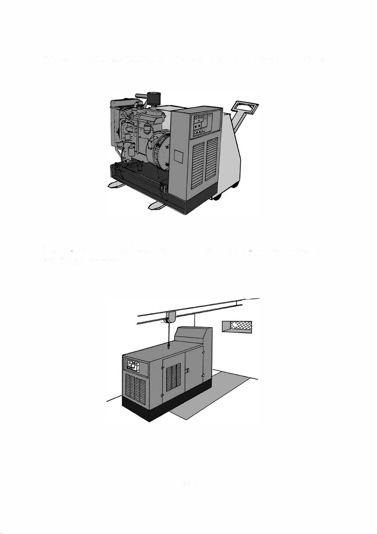
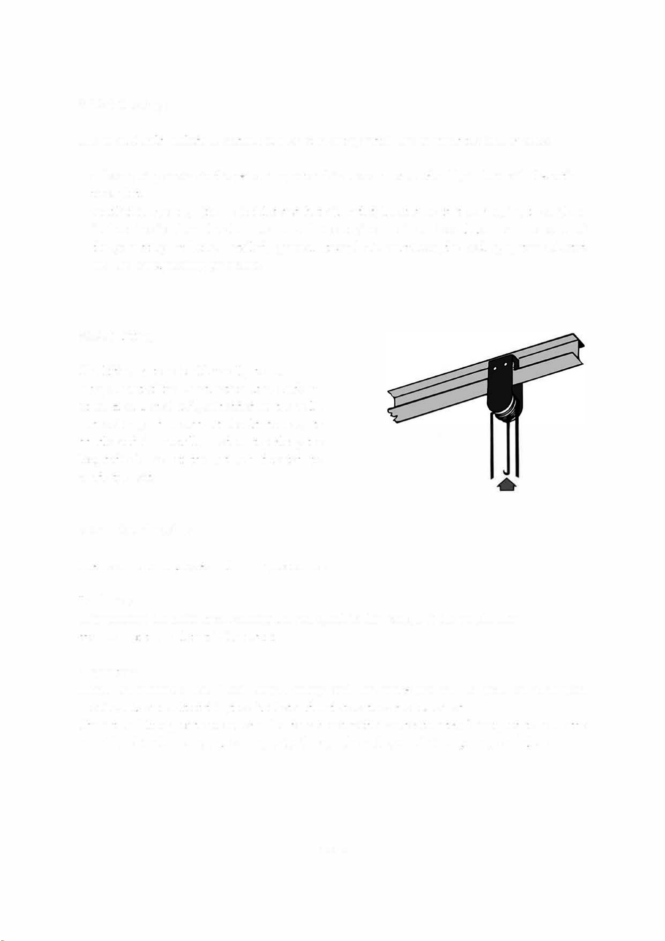
3.3.2.6 Lifting
The lifting system should usually be an
integral part of the construction. It is made up
of an H or I steel rail, embedded in the walls
and ceiling, and a crab. It should be easy to
handle and is generally used on top along the
longitudinal axis of the set and directed to-
wards the exit.
3.3.2.7 Soundproofing
The room is soundproofed using two procedures:
Insulation:
This prevents the noise from crossing the walls, and in this case, it is the weight then
thickness of the wall that is important.
Absorption:
These are materials that absorb sound energy and this procedure will be used on ventilation
openings. As a result of this, the air inlet and outlet sections are increased.
The inteal lining of the room can also be covered with absorbent material designed to lower the
sound level in the room, and consequent! y through the walls, ventilation openings and door.
- 22/42 -
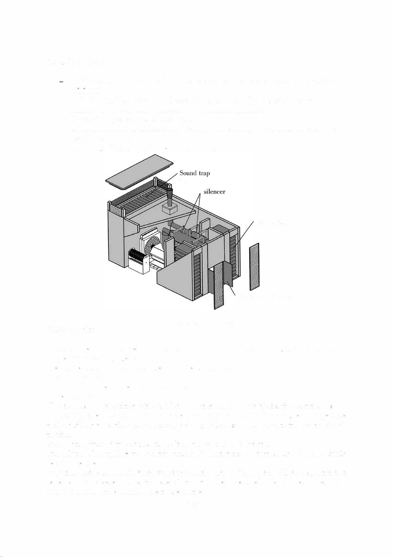
General arrangements
building sh·ucture made from framing concrete or solid concrete blocks, 20 cm thick
mm1mum
-
anti
-
vibrating floor plate under the generating set when adjoining sensitive areas.
-
ceiling and walls covered if necessary with absorbent materials
-
choice of adapted exhaust silencer (s) .
-
soWldproofed door for access to the room and, if required, to the pressure lock, for a
very low sound level.
-
soWld traps fitted to the air inlet and outlet sleeves.
3.3.2.8 Ventilatiol)
Example of installation
Sound trap
Soundproofed doors
A heat engine generates a certain amount of heat, which must be evacuated outside the room to
ensure the set works properly.
The heat released by the set originate from different sources:
-
cylinder cooling
-
radiation om the engine unit and exhaust duct
-
alternator cooling.
Also the room must be fitted with air inlet and outlet openings suitable for the conditions of use
and cooling system. As you know, insufficient ventilation will cause the atmospheric temperature
to rise and lead to problems ranging f
r
om, at least, a loss of engine power to the set stopping al
together.
Air must flow du·ough the set room from alteator engine radiator.
This solution also supplies the quantity of fresh air needed for combustion. The openings should
be of ample size.
Air intake and emission will be as direct as possible. The cooling system will be coected to a
sealed emission sleeve or cover to prevent hot air om being recycled. The air inlet and emission
openings should not be located close to one another.
- 23/42 -
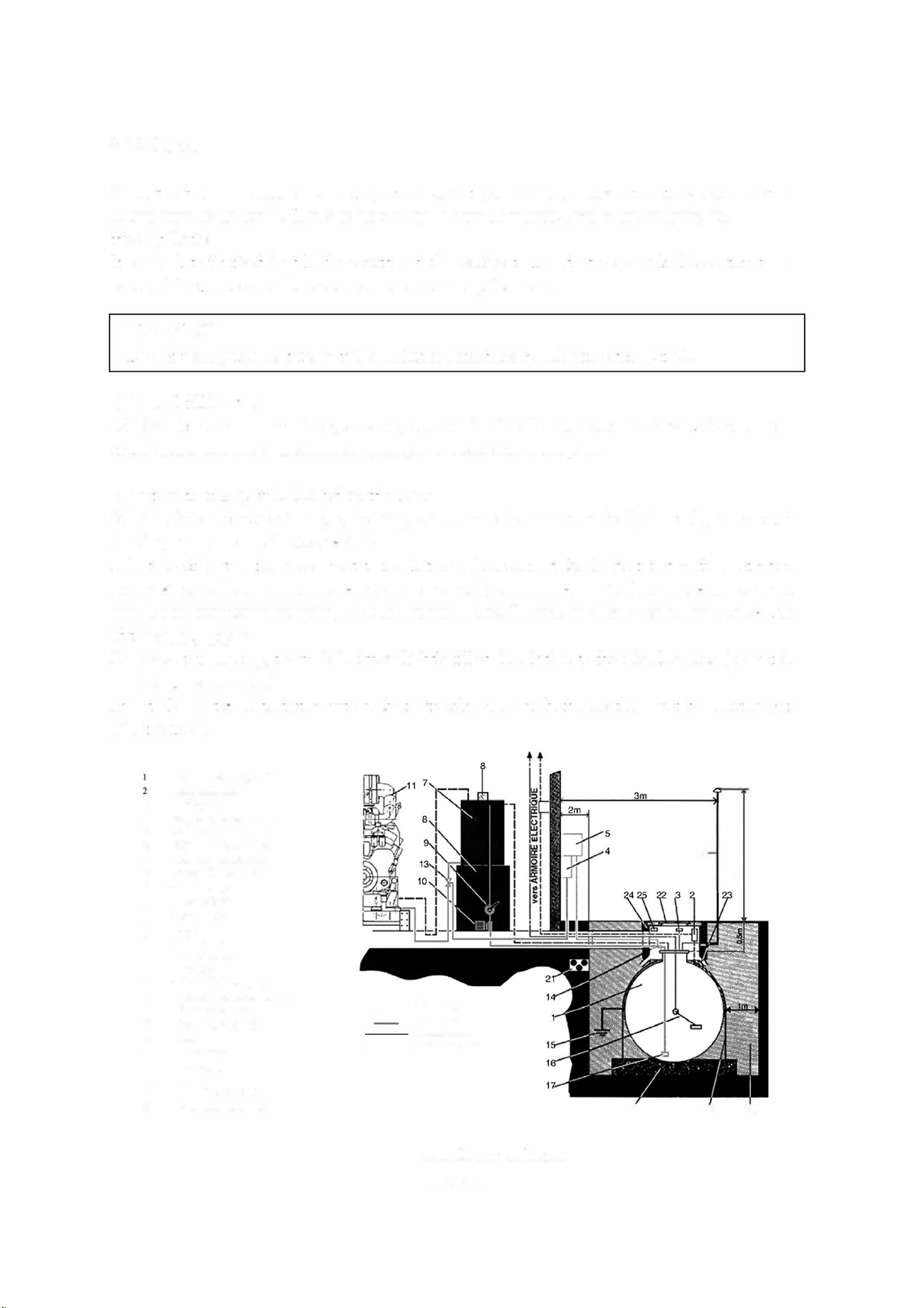
3.3.2.9 Fuel
Since the fuel is classed as a "dangerous product", certain regulations for storage and distri
bution must be followed. It is also necessary to consult current laws when carrying out
the installation.
It is usual to fit xed installations with a daily service tank and storage tank. These two tanks
can be joined into one if the generating set consumption is low.
WARNING
Do not used galvanised receptacles or brass coated receptacles for storing fuel.
a) Manual lling tank
Solution for a manual starting generating set that is visually monitored. This tank is often part
of the frame and has a mechanical gauge, filler neck and drain port.
b) Automatic lling tank located in the room
Solution for automatic sta1ting generating sets. The tank is automatically filled by an electric
drawing pump in a main storage tank.
This type of installation is subject to regulations. Moreover, it should be fitted with a retention
container capable of collecting leaks with a capacity at least equal to that of the tank. There
must be an oveiflow pipe going back to the main tank. Its section should be at least twice that
of the supply pipes.
To prevent unpriing,the tank is fitted slightly filled in relation to the diesel engine (except in
covered parking areas).
This tank must also be fitted with a shut-off valve for which the control must be located out
side the room.
- Double lin stor3ge tank
- Leak tting cell
3
- filling porl
4
- Shutff valve control unil
5 - Safety v.alve control u,,i1
6
- 6 L re1en1ion conraine
7
- 5 L daily sen·ice tank
8
- Gauge with level switch
9
- Martul puo1p
I O
- ltric pm
1
>
I I
- general ing sel
12
- Venl
13
- Sooety \"3J"e
14
- Shut-off \'ah·e
15
- rthing
1
6 - Ellrie fuc level gauge
17 - Anti-return \'ive with striner
18 - Conere1e flr
1
>lah!:
19
- Anchoring lt ( 1/m)
20 - Pits
2
1
- Pipe 1""3g•
22 - Ae plug
23
- Qr3ins
24
- �t;n hole, 0.70 x 0.70
25
-
Type ar. capacity lal
Fucl supply
fuel relurn
____ J
Electri�.al wiri,�
--- Mh:mial cable
Example of installation
- 24/42 -
18
12
19
E
20
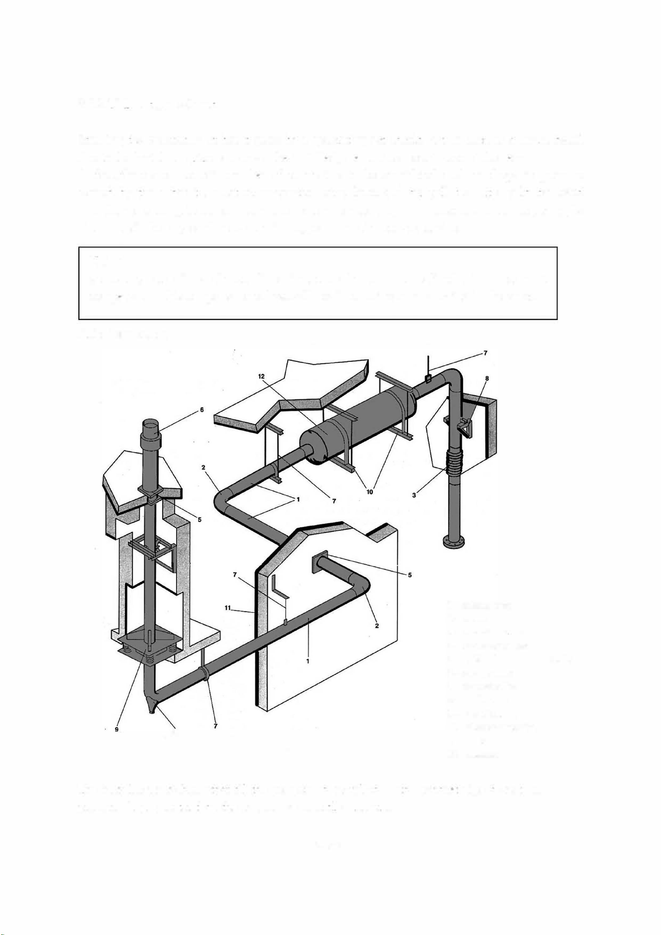
3.3.2.10 But gas exhaust
Studying the evacuation of but gases by a generating set should not be seen as a minor detail
due to the fact that a pipe can always be installed, even in the most inaccessible areas.
In fact, there are a ce1tain number of constraints to be considered such as drops in pressure
caused by the exhaust, insulation, suspension, noise level and air pollution. It should be noted
that the more complicated a circuit, the more it causes drops in pressure and consequently, its
diameter will be large and heavy and its supports and silencers expensive.
NOTE
generating sets with a silencer fitted in the enclosure must be fitted with an exhaust
compensator. This compensator or hose will be fitted to the exhaust outlet in the cover.
Main components
4
l - exhaust pipes
2 - elbows
3 - expansion bell ow
4 - condensation bleed
5 - bulkhead crossing - rf outlet
6 - exhaust outlet
7 - suspension line
8 - needle frame
9 - base of column
10 - silencer suspension
11 - heat insulation
12 - silencers
The installer must check that all the components installed on the exhaust pipe do not cause
pressure drops greater than the engine's admissible pressure.
- 25/42 -
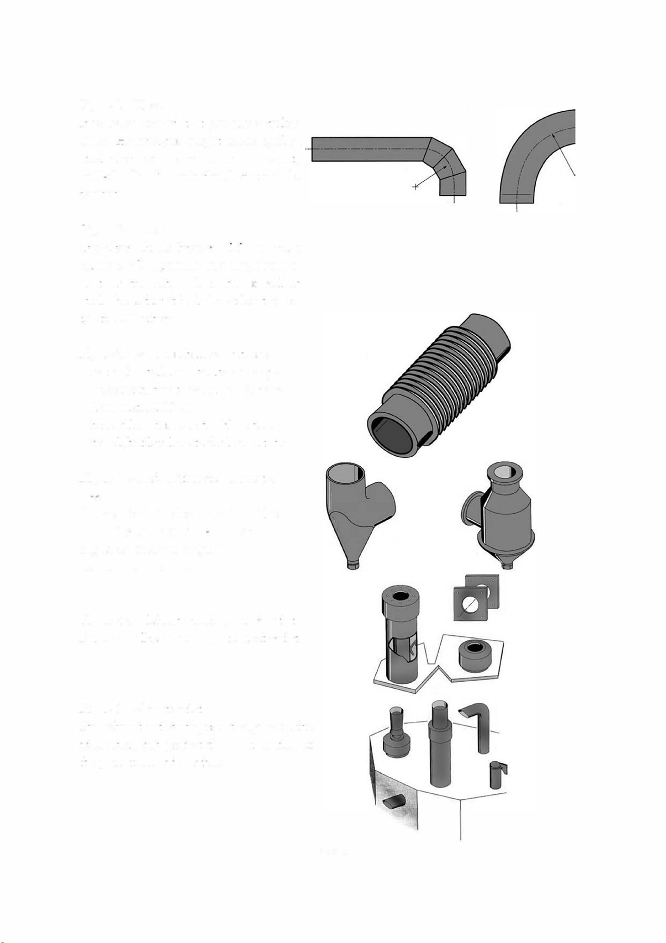
Figure 1 : Pipes
It is recommended that you use seamless
pipes. However ,r weight reasons, rolled
steel pipes can be used. In any event,
welded "bars" inside the duct are to be
avoided.
Figure 2: elbows
The elbow should have a minimum curve
radius of 2D if possible in a single compo
nent. If the elbow is made of welded
steel, check that it includes at least 3 sec
tors r 90
°
elbows.
Figure 3: expansion bellows and hoses
- expansion bellow : absorbs sideways
movements due to expansion (approx
lrnm/metre/100
°
C).
- hose: allows for considerable sideways
travel,but low longitudinal amplitude.
Figure 4 : condensation and rainwater
bleed
Allowed for in the lower section of the
instaation, to protect the silencer and
engine or for any changes in
horizontal/vertical h·avel.
Figure 5 : bulkhead crossing - roof outlet
For each bulkhead passage and roof outlet.
Figure 6: exhaust outlet
The exhaust outlets disperse the gases in the
atmosphere and protect the inner section of
the pipes f
r
om bad weather.
- 26/42 -
Figure 7: suspension line
Generally made up of a flat iron ring
attached to the ceiling. The suspension
line enables the pipes to expand freely.
Figure 8: needle frame
Used r vertical sections, the needle
frame allows the pipes to expand while
holding them laterally.
Figure 9: column base
The colunm base is designed to hold the
weight of the vertical pipes.
Figure 10: silencer suspension line
The silencer suspension lines are designed
to hold the weight of the silencers, they can
be vertical or horizontal.
Figure 11: heat insulation
t
Depending on the type of installation, you may have to insulate the heat released in the room.
Once
it has been insulated, the sur
f
ace temperature should not exceed 70 °C. The recommended
material is rock wool
(excluding asbestos) and eventually it can be recovered with aluminium
sheets to improve the look of the installation and the thermal insulation.
SO mm thick glass wool should be considered a minimum re
q
uirement.
- 27/42 -
Figure 12: silencers
These reduce noise by absorbing or causing phase differences in the sound wave. An exhaust
should be effectively suspended, the supports should never rest on the set ( except r original
fittings). An exhaust compensator will be fitted to the engine outle. The pipes will never have
a diameter less than the set (refer to us about vermin ) and be directed so that gas cannot
retu to the room.
The pipes should be fixed so that their weight is not supported by the compensator.
It should be pe1fectly straight (any misalignment could lead to a mpture).
"Adapted" silencer
The "adapted" silencer is fitted directly to
the set or cover. It is an absorption type
silencer.
A compensator is fitted between the engine
and exhaust in the covered version'.
Absorption silencer
The gas passes through a sound proof duct
made of acoustic high efficiency absorbent
material protected by a pe1forated metal
sheet.
Absorbent reactive silencer
The gas enters an expansion chamber lined
with absorbent material, supported by
pe1forated metal sheets then into an
absorbent sound proof duct.
3.3.2.11 Electricity
a) Connections - general information
In the same way as for low voltage electrical installations, running and maintenance are subject to
the standards of the relevant country.
- 28/42 -

b) Power cables
These can be unipolar or multipolar according to the power of the generating set.
Power cables should preferably be installed in ducts or on a cable tray r this purpose.
c) Battery cables
Install the batte or batteries immediately beside the electric starter motor. The wires will be
connected directly om the battery terminals to the starter motor terminals.
The first instruction to llow is to check that the polarities of battery and starter motor correspond.
The minimum section of the wires is 70mm
2
. It varies according to the power of the starter motor
but also the distance between the batteries and the set (voltage drops on the line).
3.3.2.12 Cooling
Three types of heat production must be dissipated:
- heat om the engine cooling circuit(s)
- heat radiating om the engine and exhaust
- ventilation air om the room
- exhaust gases
The systems described below evacuate and pipe the heat produced by the engine cooling circuit.
a) Ventilated radiator
The engine cooling circuit 1s connected to a tubular ribbed radiator at the end of the ame in
order to implement this procedure. This radiator is cooled by the n controlled directly by the
engme.
In all cases the air is blown in the direction om n � fanradiator.
Cooling is ensured by the circulation of air across the room.
An expansion vase can compensate for the variations in the volume of coolant uid according to
the temperature.
b) Air recooler
The engine cooling circuit is connected to an air recooler located inside or outside the room m
order to implement this procedure.
When located in the room, it operates in the same way as a ventilated radiator. The n is either
attached to the diesel engine or run by an electric motor. H the air recooler is moved outside, on
the roof or in another room, the coolant pipes are extended and cooling ventilation is supplied
om another room. In these installations the degassing conditions should be considered even
more carefully than r a radiator.
In all cases , the air cooler is cooled by the fan.
For cooling by radiator or air cooler in the room, the increase in temperature due to heat radiation
r the sizing of the installation should be taken into account.
-29/42-

c) Lost water exchanger
This type of cooling consumes a non negligible degree of water and hence there is an operating
cost to be taken into account. This the solution when local provisions ensure the ow of water
and do not allow the ventilation provisions to be made for cooling by a ventilated radiator or air
recooler.
These lost water installations consist essentially of an exchanger, with one of its circuits tted
with an expansion receptacle, connected to the engine cooling circuit. The latter's water pump
ensures circulation.The second exchanger circuit, known as raw water is connected between the
building's water supply and the drain. A valve tted upstream of the exchanger can enable and
cut o circulation. With automatic sets, this valve should also come with an electric control
(solenoid valve).
This system's heat exchange ensures engine cooling. The room needs a ventilations system and
this type of installation requires a detailed study.
d) Ventilation of the room
Extractor ns and/or air blowers can evacuate heat radiation from the engine and supply esh air
to the room and equipment in the case of exteal air coolers or lost water exchangers.
ns are being used, more fans, rather than one large one, can regulate the temperature.
Ventilation of the premises requires a detailed study and should take into account the
atmospheric air temperature and loss of pressure of components located in the air inlet and
outlet (grilles, sound traps etc.) in particular
3.3.2.13 Special arrangements
generating sets are not tted with protection against power surges caused by drops in atmospheric
pressure or manoeuvrmg.
The company does not accept any responsibility regarding damage caused by these occurrences.
However, lightning conductors can be installed, on the understanding that this does not give total
protection.
- 30/42 -

4. INSTAATION OF ME SITE SETS
4.1 General information
Besides the advice and rules given r xed sets, certain arrangements must be made r
"site" sets.
4.2 Specific arrangements
An area will be reserved to install the generating set. Its should be flat and strong enough so that
the generator does not sink into it. It could be made of concrete or even large planks tted
together.
It should be noted that a generating set that does not rest correctly on its base
(ame or trailer)
will be subject to vibrations that could cause damage to all the equipment.
The location of the set on site should be chosen r ease of fuel supply and distribution of current
to the users.
Access to the set's doors should be available at all times r safety and maintenance reasons.
Ventilation of the generating set should not be affected if there are dierent objects close by.
It will cause abnormal heating and reduced power.
But gas evacuation will take place in such a way that there is no reaspiration into the air lter
or cooling system.
The generating set's neutral speed must be used to protect people.
Eaithing is carried out using a metal post buried deeply in the ground.
These sets are to be covered or protected om bad weather by a suitable construction (see
previous sections).
- 31/42 -
5. ROAD TRAER
5.1 Trailer linkage
Before attaching the trailer, check the trailer hook on the tow vehicle; it should fit the trailer
ring per
f
ectly.
WARNING - DANGER
T
ing to tow a trailer with a non-matching device {bar, wires, cords, etc.) could lead to
serious accidents.
Also check:
- no incipient fractures or excessive wear on the hitching system.
- locking system is operating properly
To hitch the trailer, proceed as llows:
- lock the wheels to stop the trailer from moving
- lift up the rear trailer supports and lock them
- release the parking brake
- release the locking levers for the draw bar arms and adjust the ring to the same height as the
vehicle hook
- hitch the trailer,remove the locks on each side of the wheels then lift up the front wheel fully
using its handle
- connect the electrical circui of the trailer to that of the tow vehicle
- hook the handbrake safety wire onto the hook on the tow vehicle.
CORRECT
CORRECT
Tow vehicle
Tow vehicle
Trailer
Trailer
INCORRECT
INCORRECT
Tow vehicle Tow vehicle
Trailer
Trailer
- 32/42 -
5.2 Check before towing
Before towing ca out the following checks:
- wheel torquing
- lock trailer hook
- tyre pressure
- light signals working
- cover doors closed
- parking brake o
- front wheels and rear supports lifted.
- tightening and fixing the draw bar arms locking levers
- brake test for "road" type trailers
- fitting brake safety cable.
5.3 Driving
- "On-site" type trailer
These trailers are not tted with a main brake and so cannot brake when operating; the tyres are
designed for a speed of 17 mph (27 Km/h) . Therefore, it is absolutely rbidden to exceed this
speed .
- "Road" type trailer
The dving speed should be adapted to road conditions and the trailer handling.
Driving at sustained speed causes tyres to heat up; therefore it is important to stop om time to
time to check them. Excessive heating can lead to a blow out and hence a serious accident.
When reversing, do not rget to lock the overrun brake.
NOTE
Particular allenlion musl be paid lo wheel torquing on new vehicles. Indeed, during the first
few miles, heal build -ups on the wheel hubs and brake drums lead lo reduced wheel
torquing. It is therefore essential Lo check the torquing every 6 miles ( 10 kilometres) unlilno
further loosening is noted.
The torque Lest should nevertheless be carried oul before Lowing.
5.4 Unhitching the trailer
This operation should be carried out on horizontal, t , stabl ground.
- lock the wheels
- lower the ont wheel
- disconnect the road signals wire
- ret the hitch using the wheel to release the hook ring from the tow vehicle,
- release the tow vehicle
- engage the handbrake.
- 33/42 -

5.5 Implementation for installation
Procedures to be caed out:
- check that the ground is strong enough r the assembly not to sink into it
- using the front wheel, position the set as hozontally as possible
- engage the handbrake.
- lower the rear trailer supports and lock them
- 34/42 -
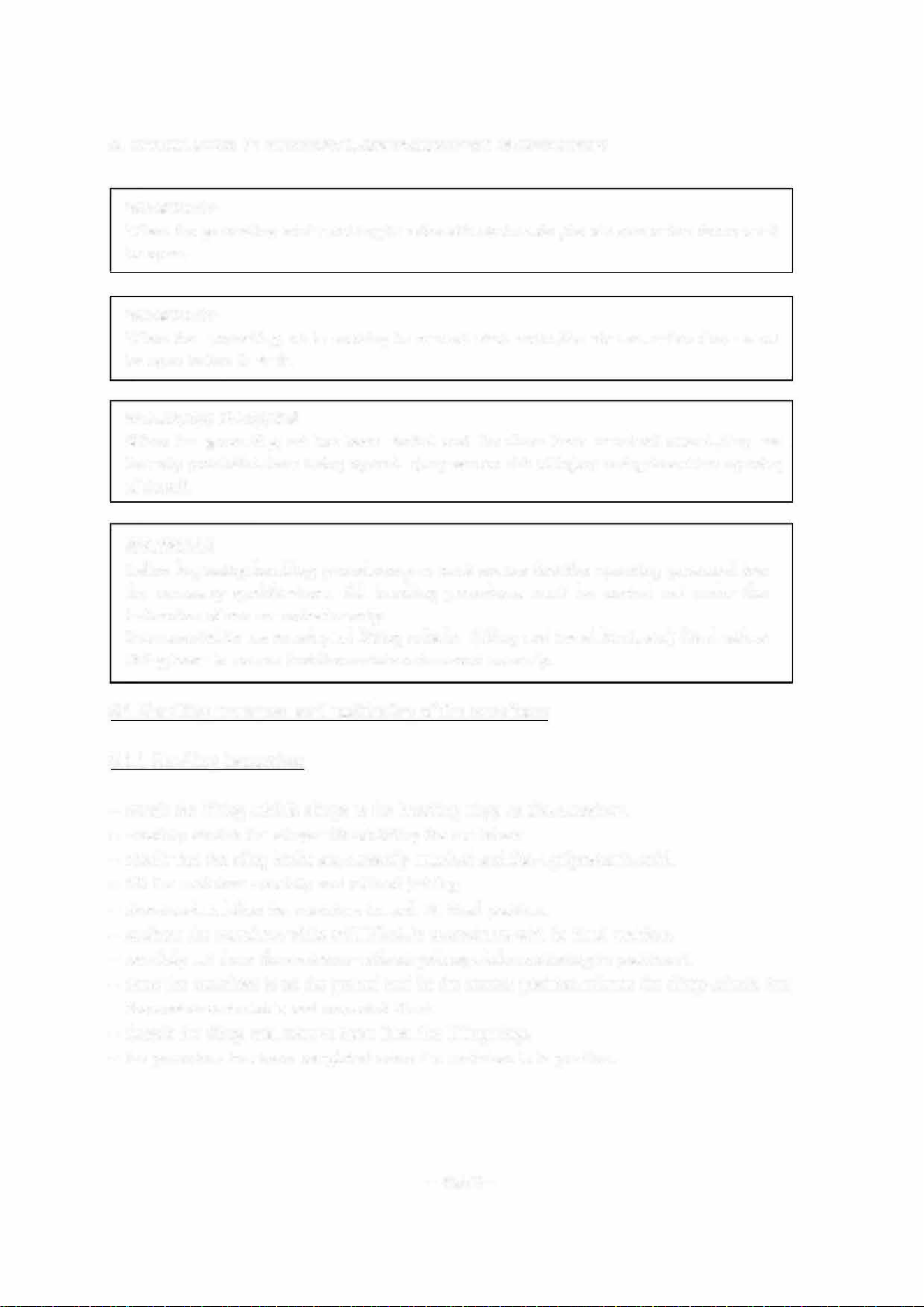
6. INSTALLATION OF ELECTRICAL GENERANG SETS IN CONTAINERS
WARNING
When the generating set is working in automatic start mode, the air evacuation doors must
be open.
WARNING
When the generating set is working in manual start mode, the air evacuation doors must
be open bere it starts.
WARNING DANGER
When the generating set has been started and the doors have remained closed, they are
rmally prohibited om being opened (very severe risk of injury owing to sudden opening
of doors).
WARNING
Bere beginning handling procedures, you must ensure that the operating personnel has
the necessa qualifications. All handling procedures must be carried out under the
instruction of one co-ordinator only.
It is essential to use an adapted lifting vehicle (lifting and travel limit,etc.) tted with a
lifting beam to ensure that the container is moved correctly.
6.1 Handling, transport and positioning of the containers
6.1.1 Handling instructions
- attach the lifting vehicle slings to the handling rings on the container.
- carefully stretch the slings without lifting the container.
- check that the sling hooks are correctly attached and the equipment is solid.
- lift the container carefully and without jerking
- direct and stabilise the container towards its nal position.
- position the container, while still lifted, in accordance with its final position.
- carefully set down the container without jerking while continuing to position it.
- once the container is on the ground and in the cmTect position, release the slings, check that
the container is stable and correct it if not
- detach the slings and remove them om the lifting rings.
- the procedure has been completed when the container is in position.
-35/42-
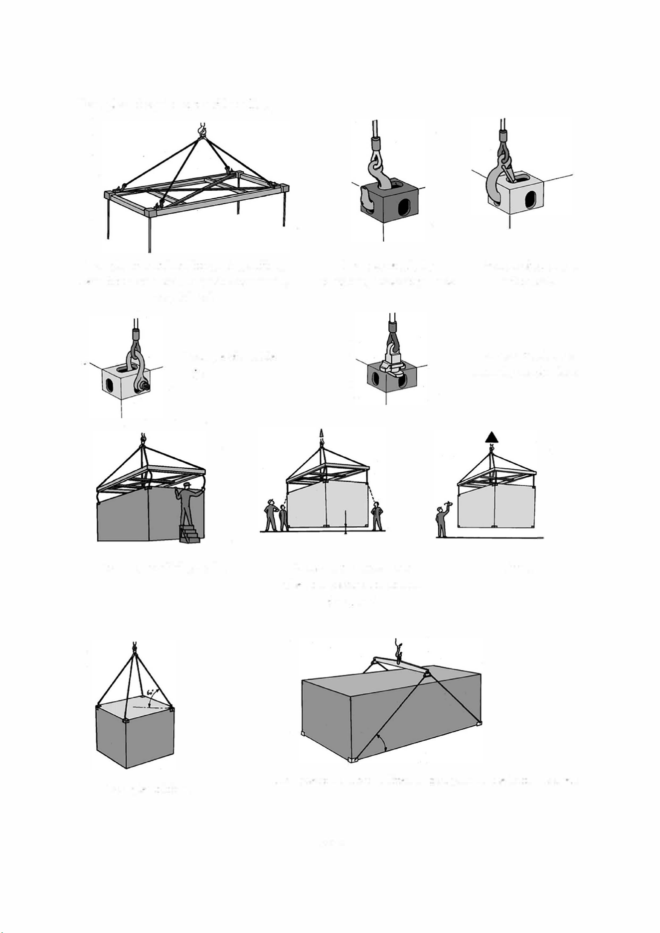
Examples of equipment and handling
Example of container lifting using a lifting
beam fitted with hooks,shackles or manually
coupled lock
Example of grip by
an ordinary hooksafety hook
Example of shackle
grip
Attachment of lifting device
Checking the attachment
when the container is still on
the ground
Example of grip by a
safely hook
Example of grip by a
manually coupled lock
lifting
Example of lifting
Example of a container lifted by four parts in the bottom coers
- 36/42 -
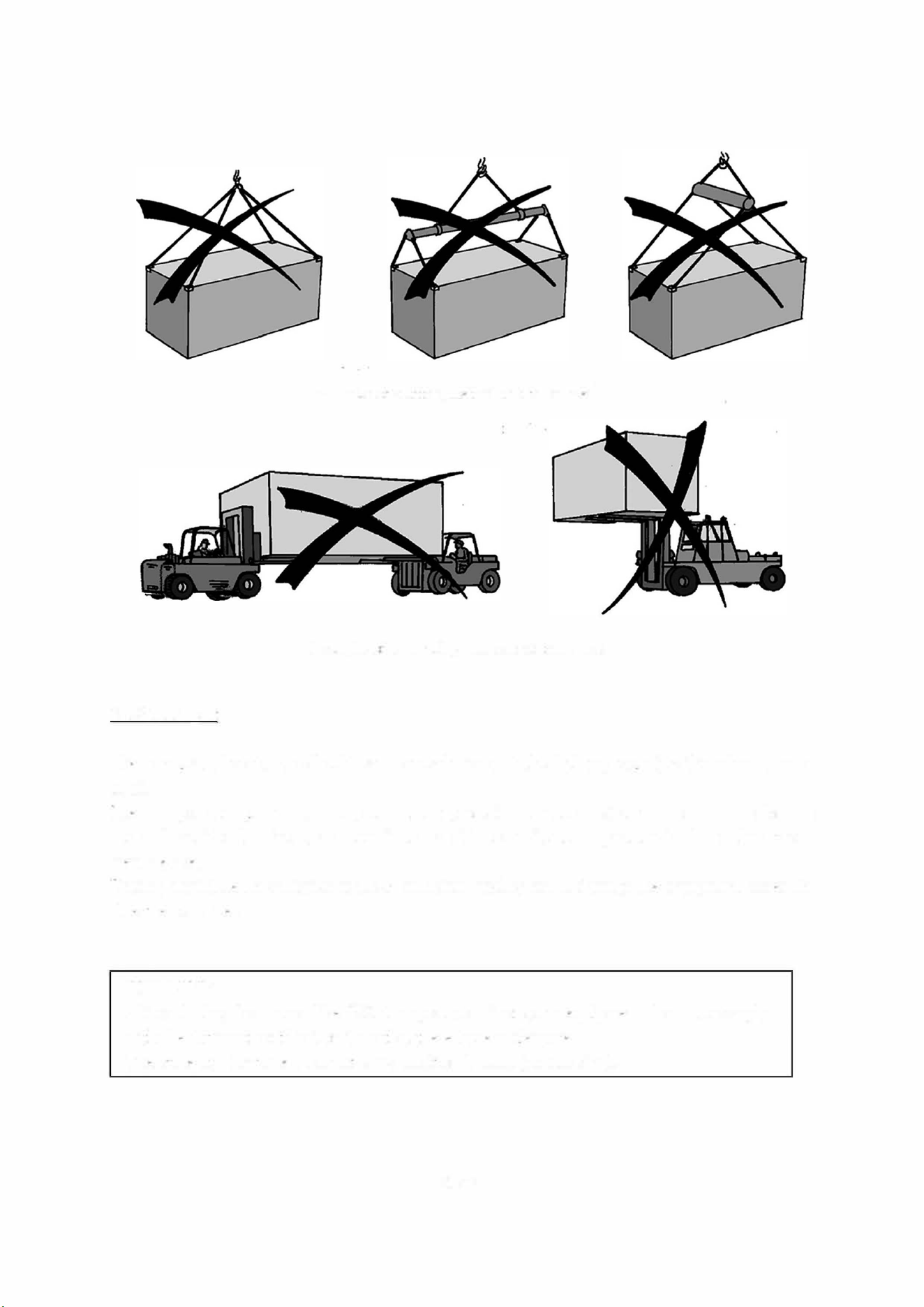
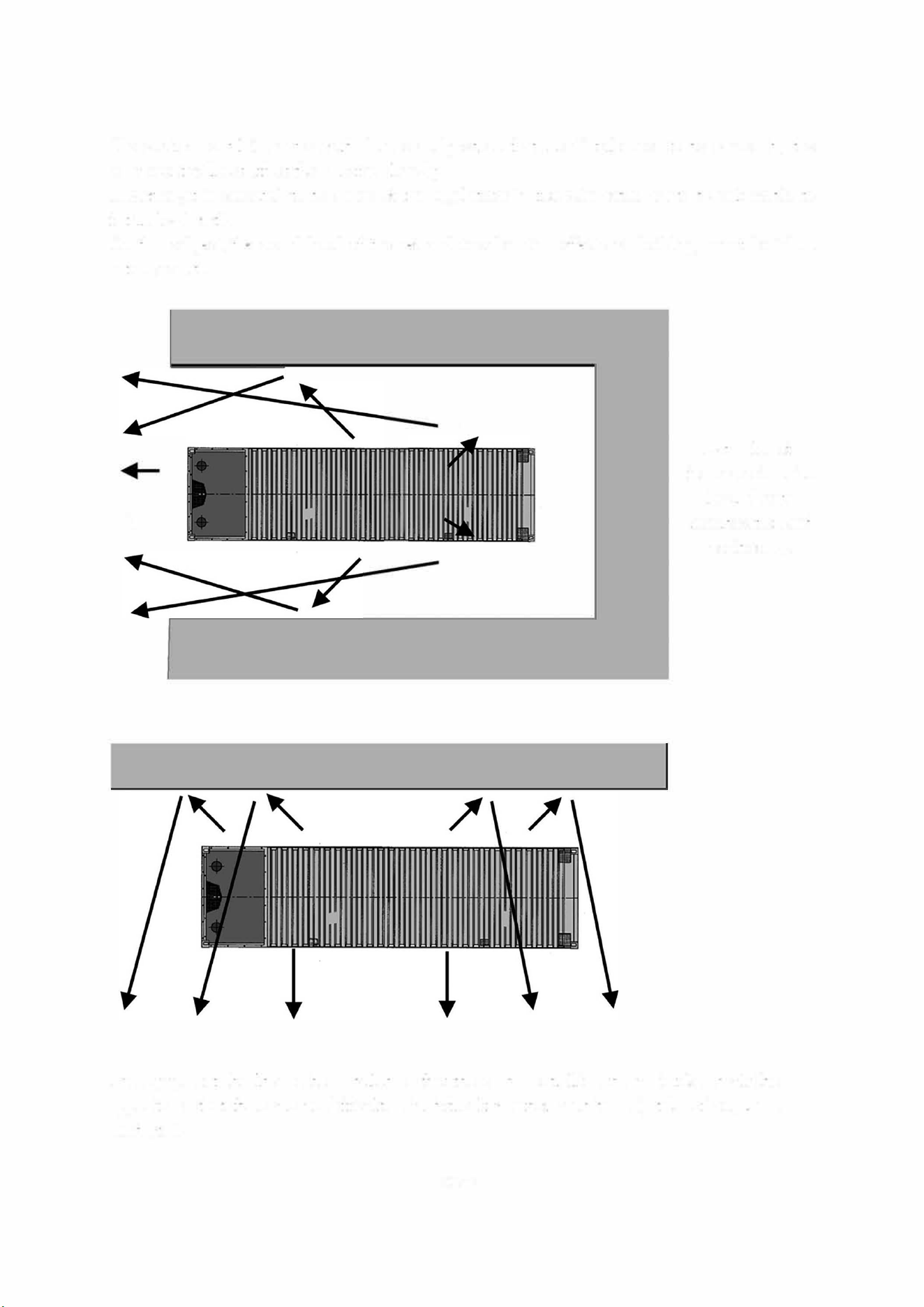
Exam
p
le of a liftin
g
method not to be used
Exam
p
le of a handlin
g
method not lo be used
6.1.2 Transport
The transport of containers should be in accordance with the highway code (
f
or the relevant coun
tries).
The transpo1t equipment
(trailer, semi-h·ailer, container holder etc.) should be suitable for this
use and provide all safety guarantees in terms of its capacity to suppo1t the load and the attach
ment devices.
Driving should be on vehicular roads of sufficient quality not to damage the equipment stored in
side the container.
WARNING
Although they look very like ISO transport containers,our equipment does not comply
with the different certification tests that these have undergone.
Therere ow- containers cannot carry additional loads (no stacking).
- 37/42 -
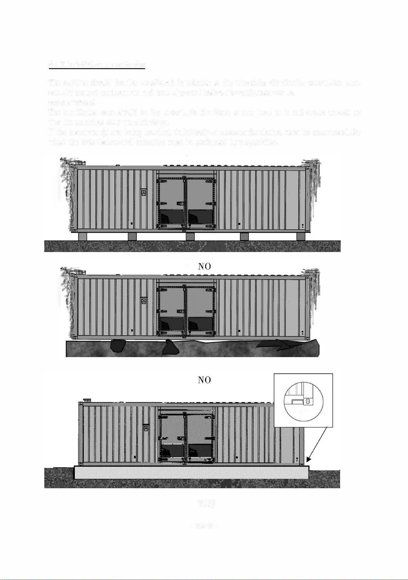
6.1.3 Installation - positioning
The position should first be considered in relation to the electricity distribution centre, fuel stor
age, the general environment and type of ground bere the equipment can be
accommodated.
The installation area should be at enough for the frame to rest level on it and strong enough so
that the container does not sink down.
If the container (s) are being installed definitively, a concrete foundation must be constructed ,r
which the calculations and execution must be peormed by a specialist.
YES
- 38/42 -
The environmental impact should also be analysed so that the disturbances to be caused by the
equipment will not aect those living close by.
Therefore, it is essential to be aware of the regulations in force, in order not to be vulnerable to
future legal action.
On this subject, the sound level of the set and reverberation effects on buildings must be taken
into account .
-
-
Examples of
. . .
increases m noise
level due to
reverberation and
positioning.
The equipment should also be installed so that the vents controlling the air intake should be
opposite so that there are no diiculties in difficult weather concli tions (intake of air, snow,
sand etc.).
- 39/42 -

6.2 Maintenance
- lubricate the hinges and locks regularly
- lubricate the joints with silicone grease
- wash and clean the bod
ork using products designed r car bodywork
- check the condition of the bod
ork and retouch any scratches straight ay (to prevent the
start of corrosion).
- 40/42 -
7. PREPARATION BEFORE OPERATG THE SET
WARNING - DANGER
The inspections referred to in this section enable the electrical generating set to operate.
Specific skills are required to carry out these operations.
They must only be entrusted to personnel with the necessary skills.
Failure to follow these instructions in any way could lead to incidents or very serious ac
cidents.
7.1 Installation checks
• check that the general recommendations om the installation section
( ventilation , exhaust, fluids etc.) are llowed
• check the levels (oil, water, diesel, battery) .
7 .2. Connection checks
•
check the remote controls by section and number
(sector, accessones, low
voltage central control panels etc.)
•
apply voltage to the accessories to check the following components
(non
comprehensive list)
►
fuel pump (consumption and direction of rotation)
► water preheating (intensity and voltage)
►
battery charger
► etc.
7.3 Starting the generating set
• carry out the mechanical checks
(oil pressure, water temperature, absence of
noise etc.)
• carry out the electrical checks (voltage and frequency)
• carry out the safety checks (emergency stop, oil pressure, water temperature
etc.)
7.4 Load test on installation
• check the rotary field
• check the voltage, frequency and intensity
• check normal/emergency switching or coupling.
- 41/42 -

Connecting the Communcations cable
You need to complete the connections of the communications cable. The process to finish this is
different depending on what RPM generator, they are as follows:
For 3000RPM generators:
1. Red wire to terminal F4 - (12Volt +)
2. Black wire to terminal 3 Wihte sleeve marked - (12 volt -)
3. Connect white wire to terminal labeled 32
4. Connect additional loop wire from terminal (Labelled 31) to terminal F4
For 1500RPM Generators:
1. Red wire to terminal F4 (12Volt +)
2. Black Wire to Terminal 3 White sleeve marked - (12 Volt -)
3. Connect Green wire to terminal Labelled 32
4. Connect additional loop wire from Terminal (Labelled 31) to terminal 3 White sleeved marked -(12
Volt -)
8. BAITERY MAINTENANCE
WARNING
-
DANGER
-
install the battery so that it has the correct ventilation
-
-
-
never place the battery close o a flame or fire
use only insulated tools
never use sulohuric acid or acid water to too uo the electrolyte level
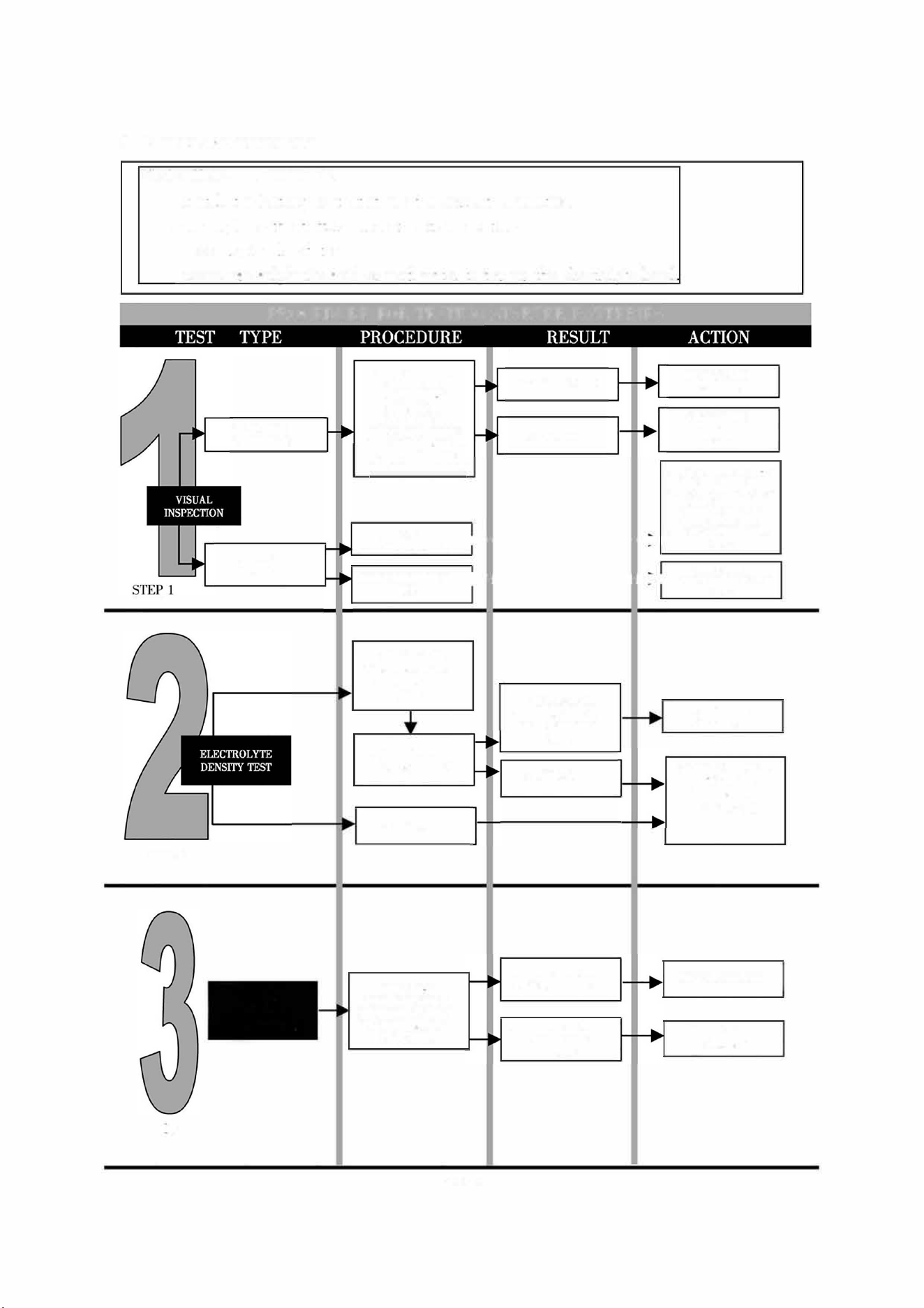
PROCEDURE FOR TESTING STARTER BA
T
TERIES
TRAY AND
TERMINALS
El.ECTROL YTE
LEVEL
CHECK THAT THE
TRAY IS NOT
BROKEN,THAT
THERE IS NO
ELECTROLYTE
LEAK AND CHECK
TH£ CONDITION OF
THE TERMINALS
(DAMAGED, BLACK)
BELOW THE
PRESCRIBED LEVEL
PRESCRIBED LEV EL
OK
< 1.22 kg/I Ofl
VAIUATION ABOVE
50 g/1 BETWEEN
CELLS
RECHARGE THE
BATTERY FULLY
> 1.22 kg/I
DAMAGE NOTED
NO DAMAGE
flEPLACE THE
BAERY
CHECK THE
ELECTROLYTE
LEVEL
ADD WATER UP TO THE
PRESCRIBED LEVEL,
CHARGE FOR 4-5 HOURS
AT 1110 OF THE
NOMINAL CAPACITY
THEN CHECK THE
ELECTROLYTE DENSITY
l--------
/sp 2)
CHECK E
[-------� ELECTROLYTE DENSITY
(,i,p 2)
< 1.22 kg/I OR
VARIATION ABOVE
50 gll BETWEEN
CEL
> 1.22kg/l
REPLACE THE
BATTERY
CARRY OUT QUICK
ECTRICAL
PERFORMANCE
TESTS (step 3)
STEP2
STEP 3
TSTOF
QIIJCK
ERICAL
PEIU'ORMANCES
CHECK THE
BATTERY USING A
MIOTRONl, WEGA
OR SLMIL.Afl TYPE
OF TESTER
THE TESTER GIVES
A POSITIVE flESULT
THE STER GIVES
A NEGATIVE
flESULT
FIT TO OPERATE
REPLACE THE
BATI'ERY

www.hyundaipowerproducts.co.uk
Declaration Of Conformity
Importer and Authorised Representative
Genpower Ltd, Isaac Way, Pembroke Dock, SA72 4RW
Country of Origin: China
Description: Diesel Generator
SKU Code: DHY18COM-1
Date of Issue: 19/08/2024
Complies
to the Following Directives
• 2006/42/EC The Machinery Directive
• 2014/35/EC Low Voltage Directive
• 2000/14/EC Noise Emission of Outdoor Equipment Directive
• 2011/65/EU RoHS Directive
Compliant
Harmonized Standards & Technical Specifications
• EN ISO 8528-13:2016
• EN ISO 12100
• EN 60204-1
• EN ISO 3744:2010
• IEC 62321-3-1:2013
• IEC 62321-5:2013
• IEC 62321-4:2013+AMD1:2017
• CSV IEC 62321-6:2015
• IEC 62321-7-1:2015
• IEC 62321-7-2:2017
• IEC 62321-8:2017
Statement of Declaration
We the importer and authorised representative of the product described confirm
conformity within the provisions of applicable regulations and directives listed
within this document.
Signed on Behalf of Genpower Ltd
Place of Issue: Genpower Ltd
Signatory Name: Roland Llewellin
Position: Managing Director
……………………………………

www.hyundaipowerproducts.co.uk
Notes

www.hyundaipowerproducts.co.uk
Notes

For Inquiries, Please Contact:
GENPOWER LTD
Isaac Way, London Road,
Pembroke Dock, UK, SA72 4RW.
T: +44 (0) 1646 687 880
E: info@hyundaipowerproducts.co.uk
www.hyundaipowerproducts.co.uk
Imported / Distributed by Genpower Ltd for
the United Kingdom & Ireland
Licensed by Hyundai Corporation Holdings, Korea