User Manual
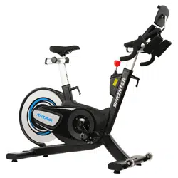
EXCEL 500 Smart Magnetic Cycling Exercise Bike
SF-B124069
EN
IMPORTANT! Please retain owner’s manual for maintenance and adjustment instructions. Your
satisfaction is very important to us, PLEASE DO NOT RETURN UNTIL YOU HAVE CONTACTED US.
1
Important Safety Information
We thank you for choosing our product. To ensure your safety and health, please use this equipment
correctly. It is important to read this entire manual before assembling and using the equipment. Safe
and effective use can only be achieved if the equipment is assembled, maintained, and used properly. It
is your responsibility to ensure that all users of the equipment are informed of all warnings and
precautions.
1. Before starting any exercise program, you should consult your physician to determine if you have
any medical or physical conditions that could put your health and safety at risk or prevent you from
using the equipment properly. Your physician’s advice is essential if you are taking medication that
affects your heart rate, blood pressure, or cholesterol level.
2. Be aware of your body’s signals. Incorrect or excessive exercise can damage your health. Stop
exercising if you experience any of the following symptoms: pain, tightness in your chest, irregular
heartbeat, shortness of breath, lightheadedness, dizziness, or feelings of nausea. If you do experience
any of these conditions, you should consult your physician before continuing with your exercise
program.
3. Keep children and pets away from the equipment. The equipment is designed for adult use only.
4. Use the equipment on a solid, flat level surface with a protective cover for your floor or carpet. To
ensure safety, the equipment should have at least 2 feet (60 cm) of free space all around it.
5. Ensure that all nuts and bolts are securely tightened before using the equipment. The safety of the
equipment can only be maintained if it is regularly examined for damage and/or wear and tear.
6. Always use the equipment as indicated. If you find any defective components while assembling or
checking the equipment, or if you hear any unusual noises coming from the equipment during
exercise, discontinue use of the equipment immediately and do not use until the problem has been
rectified.
7. Wear suitable clothing while using the equipment. Avoid wearing loose clothing that may become
entangled in the equipment.
8. Do not place fingers or objects into the moving parts of the equipment.
9. The maximum weight capacity of this unit is 330 lbs (150 kg).
10. This equipment is not suitable for therapeutic use.
11. To avoid bodily injury and/or damage to the product or property, proper lifting and moving are
required.
12. Your product is intended for use in cool and dry conditions. You should avoid storage in extreme
cold, hot or damp areas as this may lead to corrosion and other related problems.
13. This equipment is designed for indoor and home use only; it is not intended for commercial use.
Statement Of Purpose
This exercise bike is designed to help people stay healthy and fit. It provides a safe, low-impact workout
with adjustable resistance to suit different fitness levels, improving heart health, building stamina, and
burning calories. Its goal is to make regular exercise convenient, effective, and enjoyable for everyone.
Waste Disposal
SUNNY HEALTH & FITNESS products are recyclable. At the end of its useful life please dispose of this
article correctly and safely (local refuse sites).
EU Declaration Of Conformity
You can find the declaration of conformity at the following link:
https://sunnyhealthfitness.com/pages/declaration-of-conformity
Technical Data
Connectivity: Bluetooth LE
Frequency Range: 2400~2483.5 Mhz
Transmitting Power: 0 dBm
2
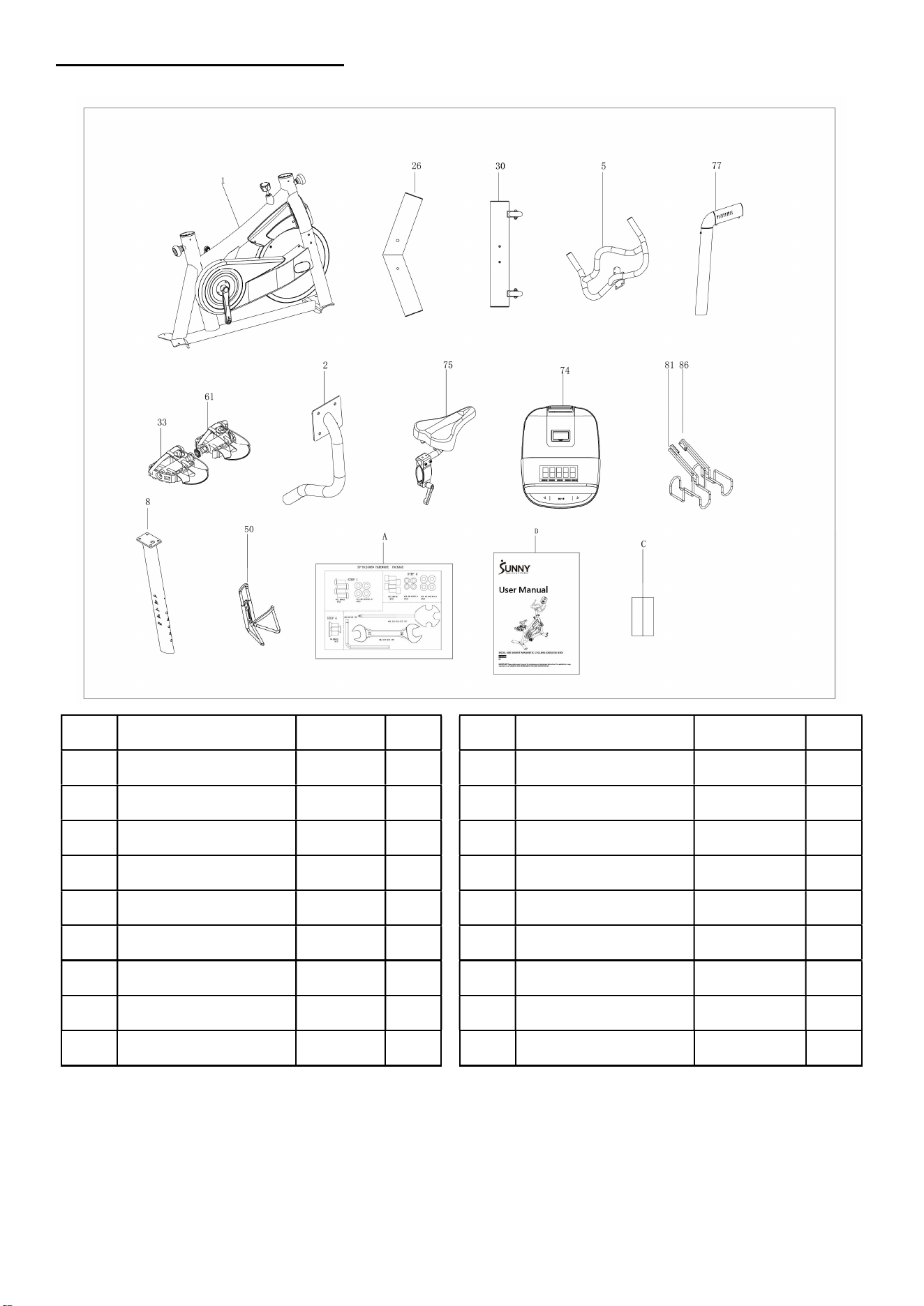
Pre-Assembly Checklist
When you open the carton, you will find the following parts:
No. Description Spec. Qty.
No. Description Spec. Qty.
1 Main Frame 1 74 Meter SF-M2501M 1
2 Meter Support Tube 1 75 Seat 280*200*120 1
5 Handlebar 1 77 Seat Post 1
8 Handlebar Post 1 81 Left Dumbbell Rack 1
26 Rear Stabilizer 1 86 Right Dumbbell Rack
1
30 Front Stabilizer 1 A Hardware Package 1
33 Right Pedal 1 B Manual 1
50 Bottle Holder 1 C Battery AA 2
61 Left Pedal 1
3
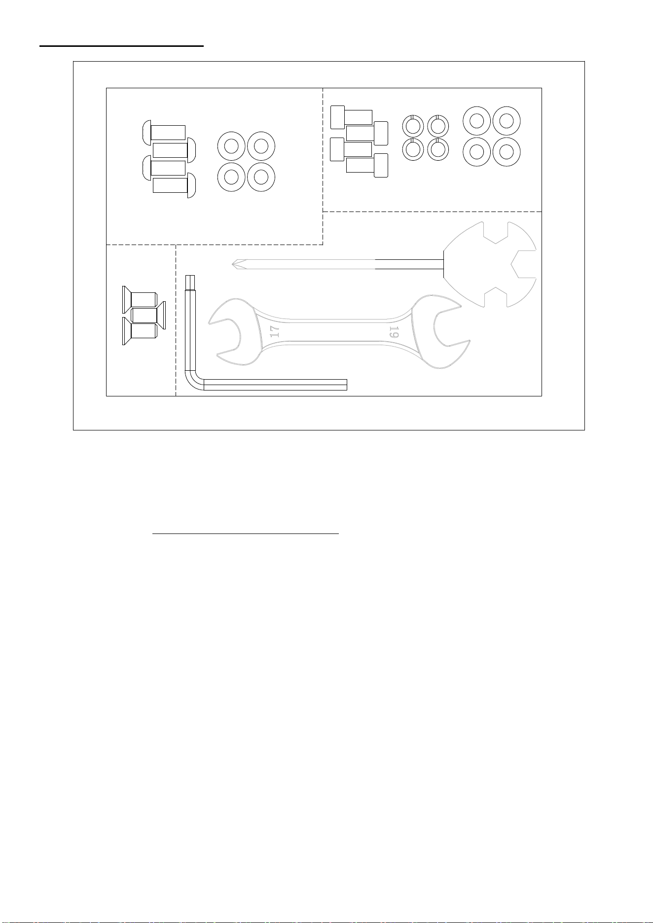
Hardware Package
#31 M8*20
4PCS
#14 d8.4*d16*1.6
4PCS
STEP 4
#4 M8*16
3PCS
#83 S13-S14-S15 1PC
#84 S17-S19 1PC
STEP 3
#12 M8*16
4PCS
#14 d8.4*d16*1.6
4PCS
#13 d8.1*d12.3
4PCS
#82 S6-S5 1PC
SF-B124069 HARDWARE PACKAGE
STEP 1
Ordering Replacement Parts
Please provide the following information in order for us to accurately identify the part(s) needed:
The model number
The product name
The part number
Please contact us at support@sunnyhealthfitness.com or 1-877-90SUNNY (877-907-8669).
4
Warning Labels
5
Assembly Instructions
We value your experience using Sunny Health and Fitness products. For assistance with parts or
troubleshooting, please contact us at support@sunnyhealthfitness.com or 1-877-90SUNNY (877-907-
8669).
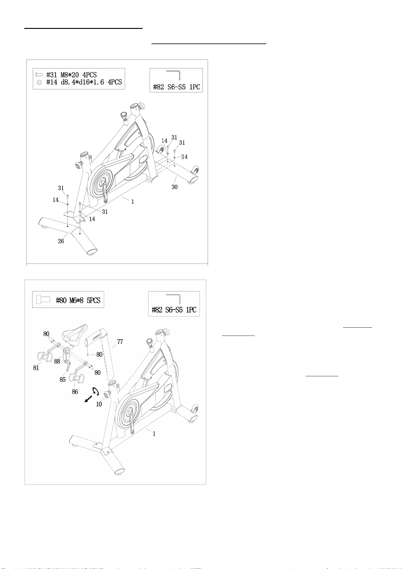
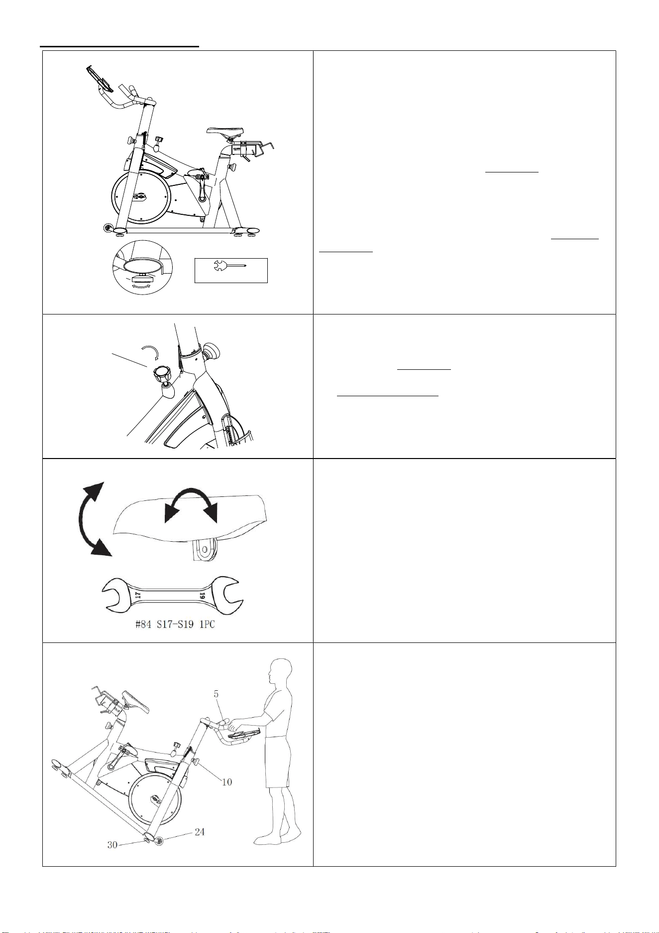
STEP 1:
Attach the Front Stabilizer (No. 30) and the
Rear Stabilizer (No. 26) to the Main Frame
(No. 1) with 4 Hex Bolts (No. 31) and 4
Washers (No. 14) using Allen Wrench (No.
82).
STEP 2:
Remove 1 Bolt (No. 80) from Seat Post (No.
77) with Allen Wrench (No. 82).
Turn the L-shaped Handle (No. 85) counter-
clockwise for 2-3 turns to loosen, attach the
Seat Plate (No. 88) to the Seat Post (No.
77), tighten 1 Bolt (No. 80) back to Seat
Post (No. 77). Slider the Seat Plate (No. 88)
to desired position, then tighten the L-
shaped Handle (No. 85) clockwise.
Loosen and pull out the Adjustment Knob
(No. 10), insert the Seat Post (No. 77) into
Main Frame (No. 1), adjust the Seat Post
(No. 77) to desired position, then secure and
tighten by Adjustment Knob (No. 10).
Remove 4 Bolts (No. 80) from Seat Plate
(No. 88) using Allen Wrench (No. 82).
Attach the Left Dumbbell Rack (No. 81) and
Right Dumbbell Rack (No. 86) to the both
sides of Seat Plate (No. 88) with 4 Bolts
(No. 80) that were just removed. Tighten
and secure with Allen Wrench (No. 82).
6
We value your experience using Sunny Health and Fitness products. For assistance with parts or
troubleshooting, please contact us at support@sunnyhealthfitness.com or 1-877-90SUNNY (877-907-
8669).
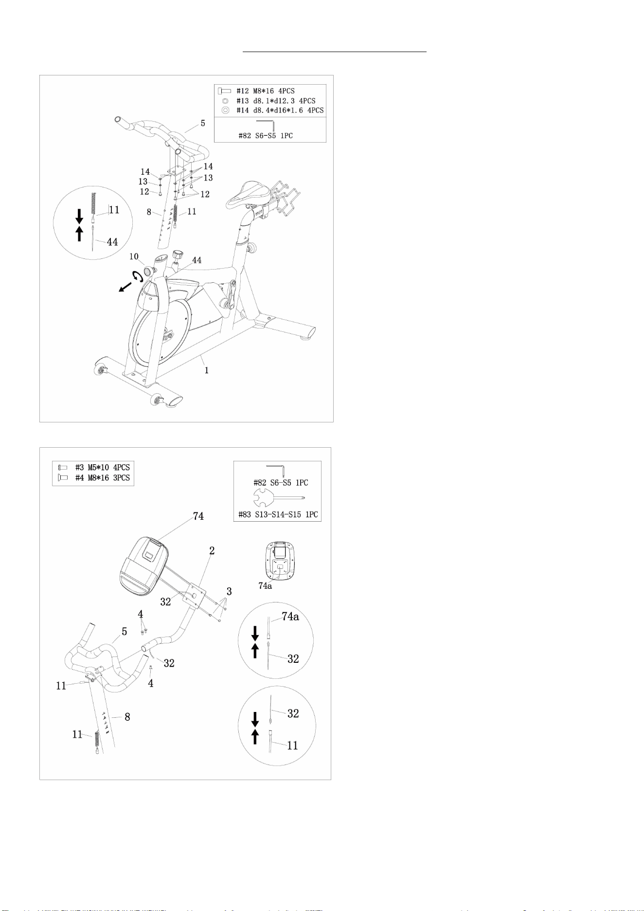
STEP 3:
Loosen and pull out the Adjustment Knob
(No. 10), insert the Handlebar Post (No. 8)
into Main Frame (No. 1), adjust the
Handlebar Post (No. 8) to desired position,
then secure and tighten by Adjustment
Knob (No. 10).
Attach the Handlebar (No. 5) onto the
Handlebar Post (No. 8) with 4 Hex Bolts
(No. 12), 4 Spring Washers (No. 13) and 4
Washers (No. 14). Secure and tighten with
Allen Wrench (No. 82).
Connect Spring Wire (No. 11) with Sensor
Wire (No. 44).
STEP 4:
Insert the Meter Support Tube (No. 2) to
the Handlebar (No. 5) with 3 Bolts (No. 4),
2pcs with the direction from top to bottom,
1pc with the direction from bottom to top.
Secure and tighten with Allen Wrench (No.
82).
Connect Upper Sensor Wire (No. 32) with
Meter Wire (No. 74a).
Remove 4 Screws (No. 3) from the back of
Meter (No. 74) using Spanner (No. 83).
Attach Meter (No. 74) to the Meter Support
Tube (No. 2) with 4 Screws (No. 3) that
were just removed. Secure and tighten with
Spanner (No. 83).
Connect Spring Wire (No. 11) with Upper
Sensor Wire (No. 32).
NOTE: Do not cut or pinch any wires when
attaching the Meter (No. 74) to the Meter
Support Tube (No. 2).
7
We value your experience using Sunny Health and Fitness products. For assistance with parts or
troubleshooting, please contact us at support@sunnyhealthfitness.com or 1-877-90SUNNY (877-907-
8669).
STEP 5:
Remove 2 Screws (No. 3) from Main Frame
(No. 1) with Spanner (No. 83). Attach the
Bottle Holder (No. 50) to the Main Frame
(No. 1) with 2 Screws (No. 3) that were just
removed. Secure and tighten with Spanner
(No. 83).
IMPORTANT! Read instructions carefully,
failure to do so may cause permanent
damage to your bike.
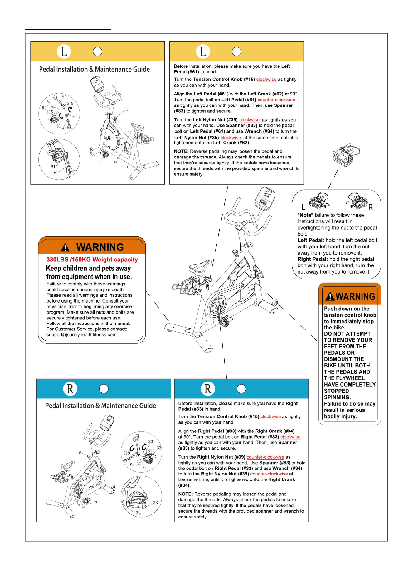
Remove the Left & Right Nylon Nuts (No.
35 & No. 39) located on the Left & Right
Pedals (No. 61 & No. 33) with Wrench (No.
84) and Spanner (No. 83). The Right Nylon
Nut (No. 39) is WHITE on the inside. The
Left Nylon Nut (No. 35) is BLUE on the
inside. Left Pedal (No. 61) is marked “L” on
it, Right Pedal (No. 33) is marked “R” on it.
Align the Left Pedal (No. 61) with the Left
Crank (No. 62) at a 90° angle. Turn the
pedal bolt on the Left Pedal (No. 61)
counter-clockwise as tightly as you can with
your hand. Then, use Wrench (No. 84) to
tighten and secure. Turn the Left Nylon Nut
(No. 35) clockwise as tightly as you can with
your hand. Use Wrench (No. 84) to hold the
pedal bolt on the Left Pedal (No. 61) and
use Spanner (No. 83) to turn the Left Nylon
Nut (No. 35) clockwise at the same time,
until it is tightened onto the Left Crank (No.
62).
Align the Right Pedal (No. 33) with the
Right Crank (No. 34) at a 90° angle. Turn
the pedal bolt on Right Pedal (No. 33)
clockwise as tightly as you can with your
hand. Then, use Wrench (No. 84) to tighten
and secure. Turn the Right Nylon Nut (No.
39) counter-clockwise as tightly as you can
with your hand. Use Wrench (No. 84) to
hold the pedal bolt on the Right Pedal (No.
33) and use Spanner (No. 83) to turn Right
Nylon Nut (No. 39) counter-clockwise at the
same time, until it is tightened onto the
Right Crank (No. 34).
THE ASSEMBLY IS COMPLETE!
8
Adjustment Guide
29
16
#83 S13-S14-S15 1PC
ADJUSTING THE BALANCE
In order to achieve a smooth and comfortable ride,
you must ensure that the bike is stabled and
secured. If you notice that the bike is unbalanced
during use, you should adjust the Foot Levelers
(No. 29) located on the front and rear stabilizers of
the bike. To do so, use Spanner (No. 83) to loosen
Hex Nut (No. 16) by turning it clockwise (direction
A). With the Hex Nut (No. 16) loosened, rotate the
Foot Leveler (No. 29) until the bike becomes
levelled with the floor surface. When you have
finished adjusting the Foot Leveler (No. 29), re-
tighten the Hex Nut (No. 16) by turning it counter-
clockwise (direction B) to complete the balance
adjustment of the bike. If required, repeat this
process to adjust the remaining the Foot Levelers
(No. 29).
15
ADJUSTING THE TENSION & EMERGENCY STOP
Adjust the tension by rotating the Tension Control
Knob (No. 15) clockwise to increase the level of
resistance. Rotate the Tension Control Knob (No.
15) counter-clockwise to decrease the level of
resistance. Push down on the Tension Control
Knob (No. 15) to enforce the brake and stop the bike
immediately.
ADJUSTING THE ANGLE OF SEAT
Use Wrench (No. 84) to unscrew the nut under the
seat. Adjust the seat to the desired angle and
reinstall the nut. Check the nut periodically to
ensure that it is tight and secure. Use the Wrench
(No. 84) to tighten when necessary.
NOTE: You will need to tighten the nut on the
opposite side at the same time. The use of an
additional spanner is required.
MOVING THE BIKE
To move the bike, first ensure that the Handlebar
(No. 5) is properly secured. If the Handlebar (No. 5)
is loose, tighten the Adjustment Knob (No. 10) to
secure it. Next, stand in front of the bike so that
you’re directly in front of the Handlebar (No. 5).
Firmly grasp and hold each side of the Handlebar
(No. 5), place one foot on the Front Stabilizer (No.
30), and tilt the bike towards you until the
Transportation Wheels (No. 24) on the Front
Stabilizer (No. 30) touches the ground. With the
Transportation Wheels (No. 24) on the ground, you
can transport the bike to the desired location with
ease.
9
ADJUSTING THE SEAT
Loosen and pull out the Adjustment Knob (No. 10)
to adjust the height of the seat. You may also slide
the seat forward or backwards by loosening the L-
shaped Handle (No. 85) on the Seat Plate (No. 88).
When adjusting, you will see a limit on the seat post.
Do not lift the post passed this mark. Always check
the Adjustment Knob (No. 10) and L-shaped
Handle (No. 85) to ensure that they are fully
secured when you finish making an adjustment.
ADJUSTING THE HANDLEBAR
It is important that the handlebar and seat are both
set to the correct height to your body. To adjust the
handlebar height, loosen and pull the Adjustment
Knob (No. 10) outward, then slide the Handlebar
(No. 5) up or down to the desired height. Once
adjusted, re-insert and tighten the Adjustment
Knob (No. 10) to secure the handlebar in place.
When adjusting, you will see a limit on the
handlebar post. Do not lift the post passed this
mark.
PEDAL STRAP ADJUSTMENT
Your feet should be secured in the toe clips during
exercise. Place your feet as far forward into the toe
clips as you can. With your feet in place, turn the
crank to bring one foot to within arm’s reach, grasp
the pedal strap and pull it upward to tighten the toe
clip cage. Then insert the strap back into the hoop
of the toe clip. Repeat this process to secure your
other foot.
DISMOUNTING:
For your safety, it is recommended that you never attempt to dismount or remove your feet from the
pedals until both the flywheel and pedals/cranks have come to a complete stop. Failure to follow this
recommendation may lead to loss of control and/or serious injury.
Here are a few examples of how to safely dismount the bike:
1. Reduce the pedal speed until the pedals/cranks come to a complete stop.
2. Increase the resistance until the pedals/cranks come to a complete stop.
3. Push and hold the brake lever down until the pedals/cranks come to a complete stop.
10
SPD Technical Service Instructions
CAUTION!
Before use, read these instructions carefully.
1. Practice engaging and disengaging from the pedals several
times in a stationary position before riding.
2. Before using, lubricate the concave area of the clip.
3. Keep the cleat and pedal clean to ensure proper usage.
4. Before using, adjust the retention force of the pedal to suit your
needs.
NOTE:
1. After tightening the cleat, practice engaging and releasing one shoe at a time.
2. Check your pedals each time before you ride the bike.
3. When the pedal starts to wear on the axle, it will not function properly. We recommend you replace
the entire pedal.
USE
Engaging
Press the cleat into the pedal.
Disengaging
Remove by twisting your heel to the outside.
ADJUSTING THE SPRING TENSION OF THE BINDING
The tension of the spring is adjusted for each pedal (top & bottom) with the adjustment bolt in the
rear using a 4mm Allen Wrench.
Using a 4mm Allen Wrench, turn the bolt in a clockwise direction to increase retention force. Turn the
bolt in a counter-clockwise direction to decrease retention force.
Decrease
Increase
4mm Allen Wrench
11
Battery Installation & Replacement
BATTERY INSTALLATION
1. Take out 2 AA batteries from meter box.
2. Press the buckle of battery cover on the Meter (No. 74), then remove battery cover.
3. Install 2 AA batteries into the battery case on the back of the Meter (No. 74). Pay attention to the
battery + and – poles before installing.
4. Press the buckle of battery cover, then put the battery cover back to the back of the Meter (No. 74).
The installation is complete!
BATTERY REPLACEMENT
1. Press the buckle of battery cover on the back of the Meter (No. 74), then remove battery cover.
2. Remove the 2 old AA batteries in the battery case and install 2 new AA batteries into the battery case
on the back of the Meter (No. 74). Pay attention to the battery + and – poles before installing.
3. Press the buckle of battery cover, then put the battery cover back to the back of the Meter (No. 74).
The replacement is complete!
BATTERY DISPOSAL
Dispose the batteries according to the laws and regulations of your local region. Some batteries may be
recycled. When disposing or recycling, do not mix battery types.
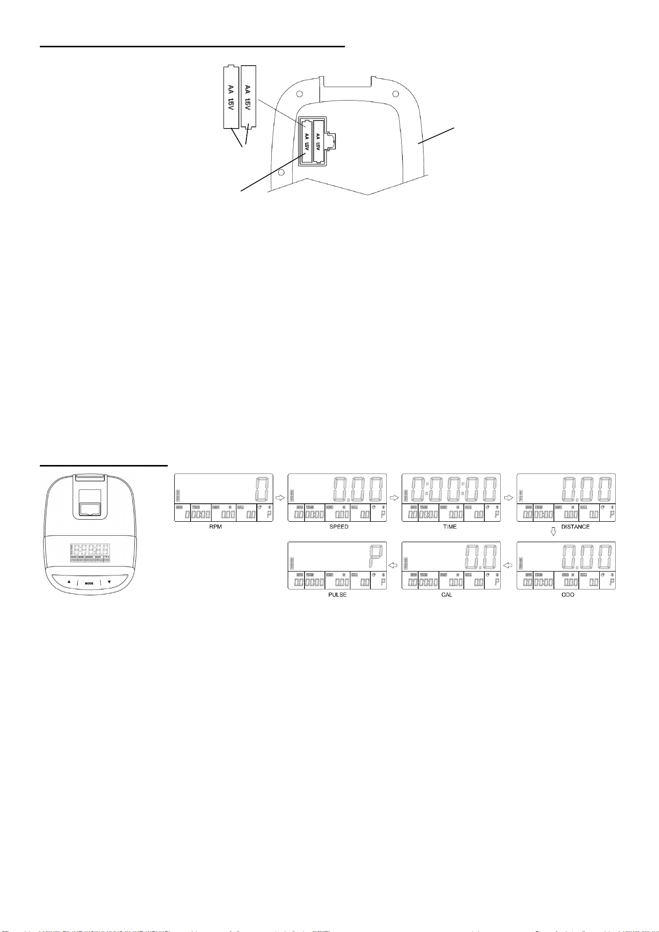
Exercise Meter
FUNCTION BUTTONS:
MODE:
1. Press the button for selecting a particular function you want to show on the main window:
SCAN→RPM→SPD (SPEED)→TIME→DIST (DISTANCE)→ODO→CAL (CALORIES)→PULSE→SCAN.
2. In stop mode, press the button to switch each setting item TIME, DIST (DISTANCE), CAL (CALORIES)
and PULSE.
3. Press and hold with 3 seconds to reset the value to zero (except ODO) when Bluetooth is not
connected.
4. Press and hold the MODE button for 6 seconds to disconnect from both the SunnyFit APP and the
heart rate monitor; then the meter will enter sleep mode.
and :
1. In stop mode, adjust upwards or downwards to set the target value for TIME→DIST (DISTANCE)→CAL
(CALORIES)→PULSE.
2. If the pulse limit is set, when the heart rate exceeds the set limit, the meter will have a “DI DI” voice
prompt.
FUNCTIONS:
1. SCAN:
Display changes according to the following order every 6 seconds, and the “SCAN” icon is flash.
RPM→SPD (SPEED)→TIME→DIST (DISTANCE)→ODO→CAL (CALORIES)→PULSE
2. RPM:
Display the current number of turns per minute of the wheel to measure the speed of the pedal.
3. SPD (SPEED):
Displays the current training speed.
Battery Cover
Battery
74

12
4. TMR (TIME):
Accumulates total time.
The user may preset target time by pressing and buttons in stop mode. Each increment is 5
minutes. When a target time is set, the meter will automatically count down from target value during
exercise. When the value count to 0, the meter will have a “DI DI” voice prompt, then resume
counting upwards. When no target time is set, the meter will count upwards during exercise.
5. DST (DISTANCE):
Accumulates the current distance.
The user may preset target distance by pressing the and buttons in stop mode. Each increment
is 0.5 M (Miles) or KM. When a target distance is set, the meter will automatically count down from
targeting value during exercise. When the value count to 0, the meter will have a “DI DI” voice
prompt, then resume counting upwards. When no target distance is set, the meter will count
upwards during exercise.
6. ODO (ODOMETER):
Displays the total accumulated distance.
7. CAL (CALORIES):
Accumulates calories burned during training.
The user may preset the target calories before training by pressing the and buttons in stop
mode. Each setting increment is 10 Cal. When a target calorie is set, the meter will automatically
count down from targeting value during exercise. When the value count to 0, the meter will have a
“DI DI” voice prompt, then resume counting upwards. When no target calories is set, the meter will
count upwards during exercise.
8. PUL (PULSE):
The meter will display the user's heart rate in beats per minute (BPM) during training. When the
heart rate is detected, the icon is on.
The user may preset the target pulse before training by pressing the and buttons in stop mode.
When the heart rate exceeds the targeting value, the meter will have a “DI DI” voice prompt.
SLEEP MODE:
1. The meter turns off automatically and disconnect the heart rate monitor if there is no signal input
and no button is pressed for approximately 4 minutes when Bluetooth is not connected.
2. The meter turns on when there is a button pressed or there is a signal input from the sensor.
SWITCH BETWEEN IMPERIAL AND METRIC SYSTEM:
Press and hold the and buttons for about 0.2 seconds to switch between imperial and metric
system.
BLUETOOTH :
1. The Bluetooth icon will flash when the meter is on or wakes from sleep mode. If no Bluetooth
connection is established within 3 minutes, the Bluetooth icon will turn off.
2. The Bluetooth icon will stay on when it is connected.
WIRELESS HEART RATE :
1. The wireless heart rate icon will flash when the meter is on. If the heart rate monitor is not connected
within 1 minute, the wireless heart rate icon will turn off.
2. After exercise resumes, the wireless heart rate icon will flash. If the heart rate monitor is not
connected within 1 minute, the wireless heart rate icon will turn off.
3. When the meter wakes from sleep mode, the wireless heart rate icon will flash. If the heart rate
monitor is not connected within 1 minute, the wireless heart rate icon will turn off.
4. The wireless heart rate icon will flash when there is the button pressed. If the heart rate monitor is not
connected within 1 minute, the wireless heart rate icon will turn off.
5. The wireless heart rate icon will stay on when the heart rate monitor is connected.
NOTE:
1. The heart rate monitor is not included. Wireless heart rate function works with SunnyFit Heart Rate
Monitor HR200. HR200 can only connect to the meter when the wireless heart rate icon is flashing.
2. The information displayed is an estimate only. Actual values may vary depending on factors such as
body weight, resistance level, workout intensity, and other individual conditions. The information is
provided for reference purposes only and should not be used for medical or dietary purposes.
3. If the meter display is abnormal, please install new batteries and try again. Always change both
batteries at the same time. Do not mix battery types and do not mix old and new batteries.
4. Battery Spec: 1.5V UM-4 or AA (2PCS).
5. Dispose the batteries safely, according to your state and regional guidelines.
APP CONNECTION
Connect Smart Equipment to SunnyFit App:
1. Scan to download SunnyFit from the app store:
2. Ensure that the Bluetooth function is turned on from your mobile device.

13
3. If this is your first time using the SunnyFit app, follow the in-app instructions to register for your free
SunnyFit account and log in.
4. Begin any workout activity that matches your smart equipment, then follow the onscreen prompts to
search for and connect to your smart equipment.
5. When connected, your stats and records will be displayed at the end of your course/session, and
recorded in your account profile!
TROUBLESHOOTING
If you are having trouble connecting your smart equipment, visit www.sunnyfit.com/guide or scan
the QR code below:
If you require additional support, please contact suppo[email protected].
Maintenance Instructions
This is general information for daily, weekly, and monthly maintenance to be performed on your bike.
DAILY MAINTENANCE
After each exercise session, wipe down all the
equipment: seat, frame, and handlebars. Pay
special attention to the seat post, handlebar post
and belt/chain guard. Sweat is very corrosive and
may cause problems that require parts
replacement later.
1. Get on the bike and engage the drive train.
2. Pay attention to any vibrations felt through
the pedals. If you feel any vibrations, you may
need to tighten the pedals, bottom bracket, or
adjust the drive belt/chain tension.
3. Use a wrench to tighten the pedals until they
are secure.
MONTHLY MAINTENANCE
1. Check all hardware is secure, such as: bottle
holder, flywheel nuts, belt/chain guard bolts,
brake caliper lock nuts and brake caliper
tension rod nuts.
2. Inspect the brake tension rod for signs of wear
such as missing threads. Clean and lubricate
the brake tension rod.
3. Clean and lubricate the seat post, handlebar
post and seat slider. Remove any buildup of
foreign material.
WEEKLY MAINTENANCE
1. Inspect moving parts and tighten the
hardware.
2. Inspect pull pin frame fittings, making sure
the fittings are snug. Loose frame fittings may
strip out threads over time and cause
extensive damage.
3. Clean and lubricate pop pin assemblies. Pull
on the pin and spray a small amount of
lubricant onto the shaft.
4. Tighten the seat hardware, making sure the
seat is level and centered.
5. Brush and treat the resistance pads. Remove
any foreign material that may have collected
on the pads. Spray the pads with silicone
lubricant. This helps to reduce noise from
friction between the pads and the flywheel.
6. Visually inspect the bottom bracket, toe clips
and toe straps. If any of them are loose or
disconnected, attach and tighten.
LEATHER BRAKE PAD CARE (If Applicable)
1. Perform this maintenance when the brake
pad is first installed and for the life of the
brake pad. Following these simple guidelines
can increase the life of your brake pads.
2. Some brake pad assemblies are pre-
lubricated. Squeeze the brake pad. If lubricant
is released, then the pad has been pre-
lubricated.
3. If the brake pad is dry, then coat the brake pad
with 3-n-1 oil. Brush the leather with a clean,
wire bristle brush, and then apply the oil. The
oil should be allowed to soak into the pad.
Repeat 4-5 times until the pad is saturated,
but not dripping with oil. When the pad is
saturated, it will no longer absorb oil.
4. Inspect the brake pad weekly and lubricate if
needed. The pad should not have a glazed
appearance. If the pad appears glazed, then
brush it with wire brush and apply lubricant as
needed. If any of the sponge padding is
showing through the leather pad, the brake
pad should be replaced.
14
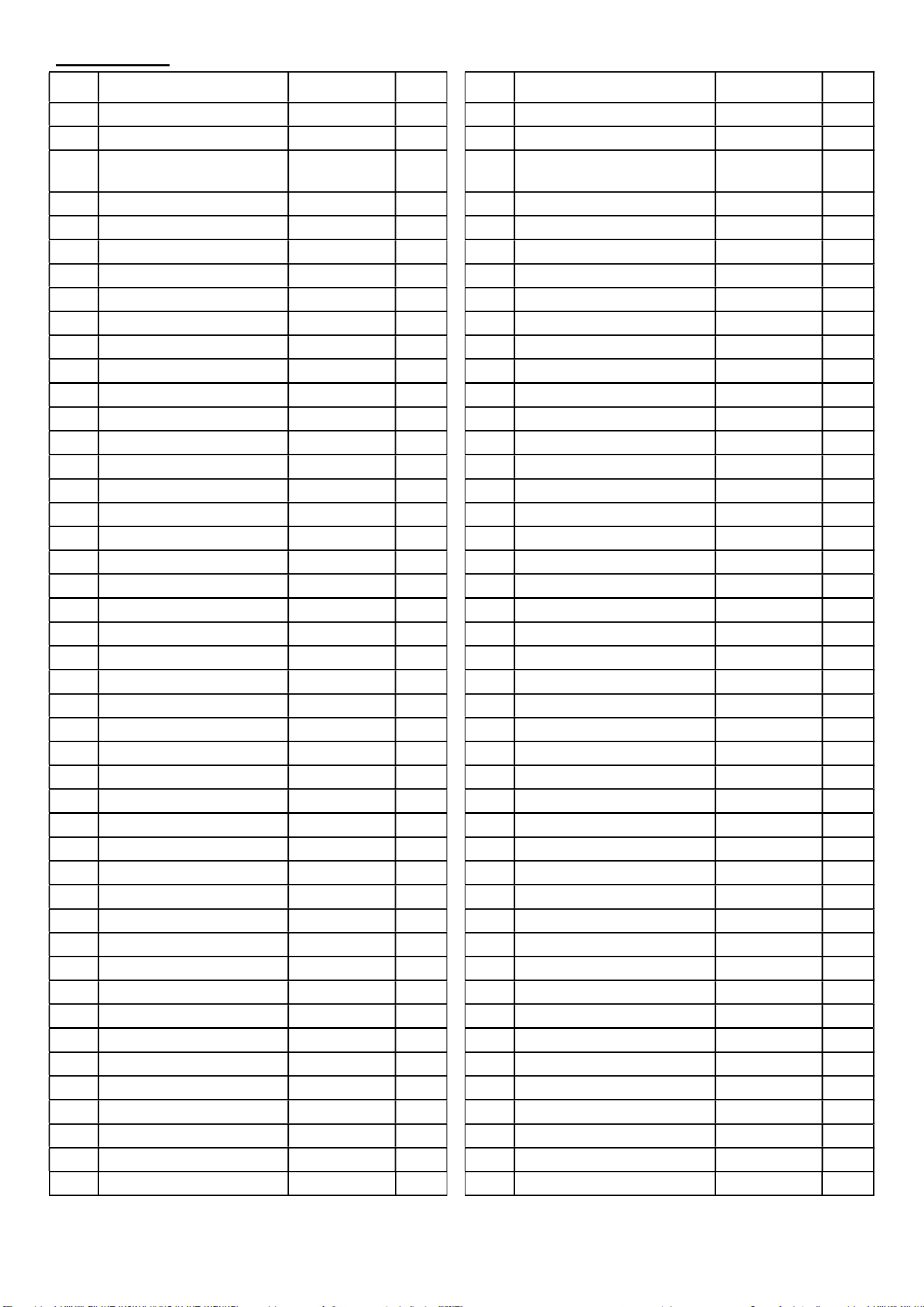
Parts List
No.
Description Spec. Qty.
No.
Description Spec. Qty.
1
Main Frame
1
46
Screw
ST4.2*12
16
2
Meter Support Tube
1
47
Sensor Bracket
1
3
Cross
-
groove
W
asher
Head Screw
M5*10 6 48
Hexagon Socket
Countersunk Bolt
M5*15 2
4
Bolt
M
8*16
3
49
Right Cant Beam Cover
1
5
Handlebar
1
50
Bottle Holder
1
6
Grommet
d14.5*d4
4
51
Left
Cant Beam Cover
1
7
Hex Bolt
M
5*10
5
52
Inner Thread
Hex Screw
M6
1
8
Handlebar Post
1
53
Outer Thread
Hex Screw
M6
1
9
Bushing
40
*
8
0
2
54
Bearing
6004
2
10
Adjustment Kno
b
M
16
2
55
Cow Leather
30*35*T8
1
11
Spring Wire
L350
1
56
Magnet Seat
20*163
1
12
Hex Bolt
M8*1
6
4
57
Spring
d12*47
1
13
Spring Washer
d8.1*d12.3
4
58
C
-
clip
d20
2
14
Washer
d8.4*d16*1.6
12
59
Middle Axle Cover
d50
1
15
Tension Control Knob
M8
1
60
Wave Washer
d20
1
16
Hex Nut
M8
7
61
Left Pedal
9/16L,
SPD
1
17
Brake Cover 1
1
62
Left Crank
175L
1
18
Brake Inner Liner
d10.2*110
1
63
Flywheel
13KG
1
19
Brake Rod
d10*M8
1
64
Flywheel Cover
d380
2
20
Square Nut
M
10
1
65
Cap Nut
M12
1
21
Bearing
6002
2
66
Adjusting Bolt
M8
2
22
Cap Nut
M8
1
67
T
hin Nut
M12
4
23
Brake Cover 2
1
68
Spacer
d21
1
24
Transportation Wheel
d8.5*d70
2
69
Bearing
6202
1
25
Nylon Nut
M8
2
70
Limit Spacer
d19*47
1
26
Rear Stabilizer
1
71
Flywheel Axle
d15*165
1
27
Hex Bolt
M8*45
2
72
Screw
ST4.2*25
8
28
End Cap
95*40
4
73
Conical Bushing
d12.2*d22
2
29
Foot Leveler
M8
5
74
Meter
S
F
-
M2501M
1
30
Front Stabilizer
1
74a
Meter Wire
1
31
Hex Bolt
M8*20
4
75
Seat
280*200*120
1
32
Upper
Sensor
Wire
450mm
1
76
Knurling
S
haft
d20
1
33
Right Pedal
9/16R,
SPD
1
77
Seat Post
1
34
Right Crank
175R
1
78
Seat Post
Plug
30*70
1
35
Left Nylon Nut
9/16
1
79
Tightening
S
crew
M
5
2
36
Crank Cap
D22
2
80
Bolt
M6*8
5
37
Flange Nut
M12
2
81
Left
Dumbbell Rack
1
38
Outer Belt Cover
1
82
Allen Wrench
S6
-
S5
1
39
Right
Nylon Nut
9/16
1
83
Spanner
S13
-
S14
-
15
1
40
Belt
L1345
1
84
Wrench
S17
-
S19
1
41
Belt Wheel
d240
-
5PK
1
85
L
-
shaped Handle
1
42
Inner Belt Cover
284*442
1
86
Right
Dumbbell Rack
1
43
End Cap
54*94
1
87
Bushing
2
44
Sensor Wire
L70
0
1
88
Seat Plate
1
45
Front Cover
1
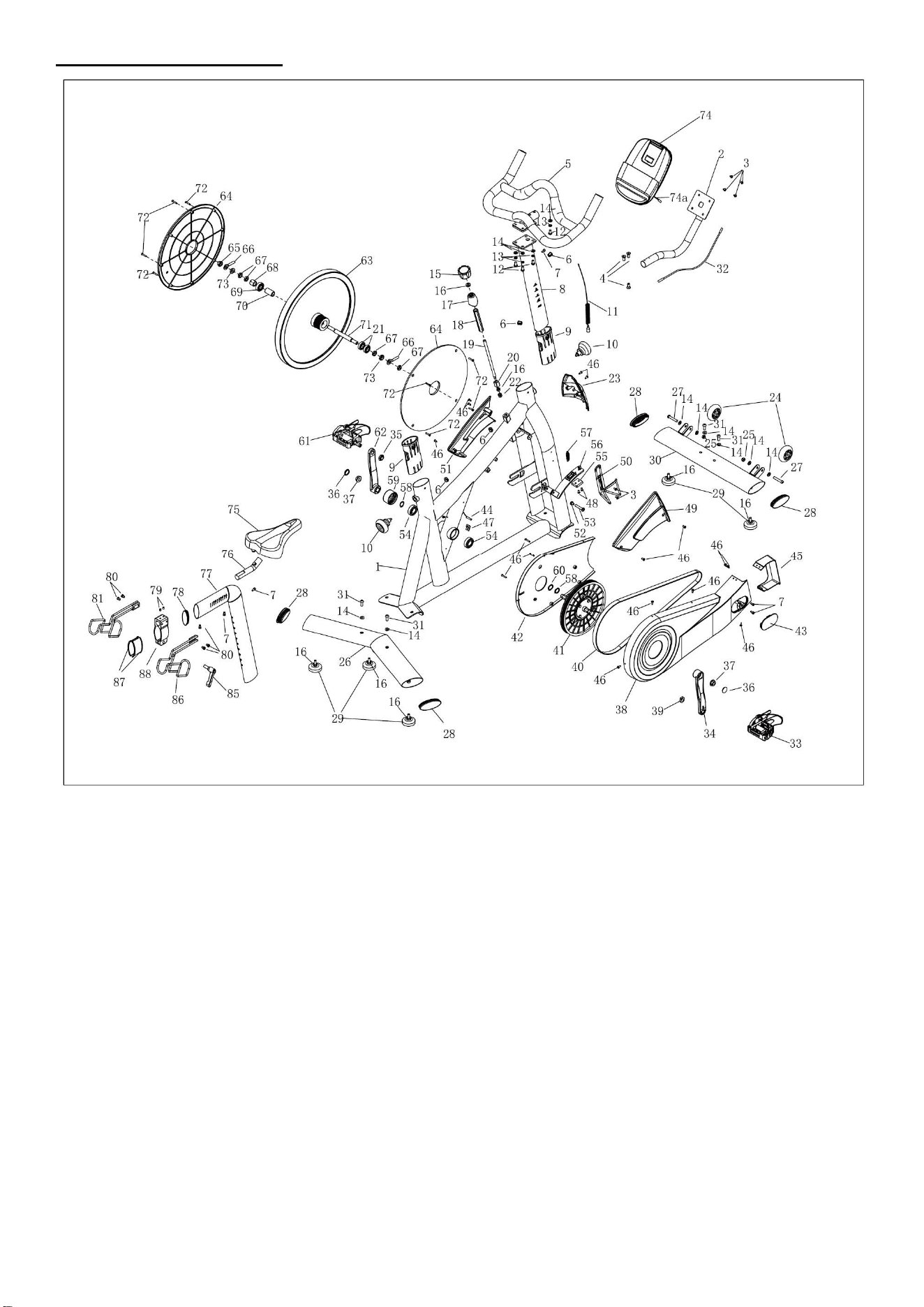
15
Exploded Diagram
Version 1.0

Register
Register your product and verify warranty terms:
Sunnyhealthfitness.com/warranty
Download
Track your fitness progress & join FREE workout courses!
Download SunnyFit App today!
Follow
Find us on social media
Contact
Get in touch with us for any questions
1-877-90SUNNY (877-907-8669)
support@sunnyhealthfitness.com
www.sunnyhealthfitness.com