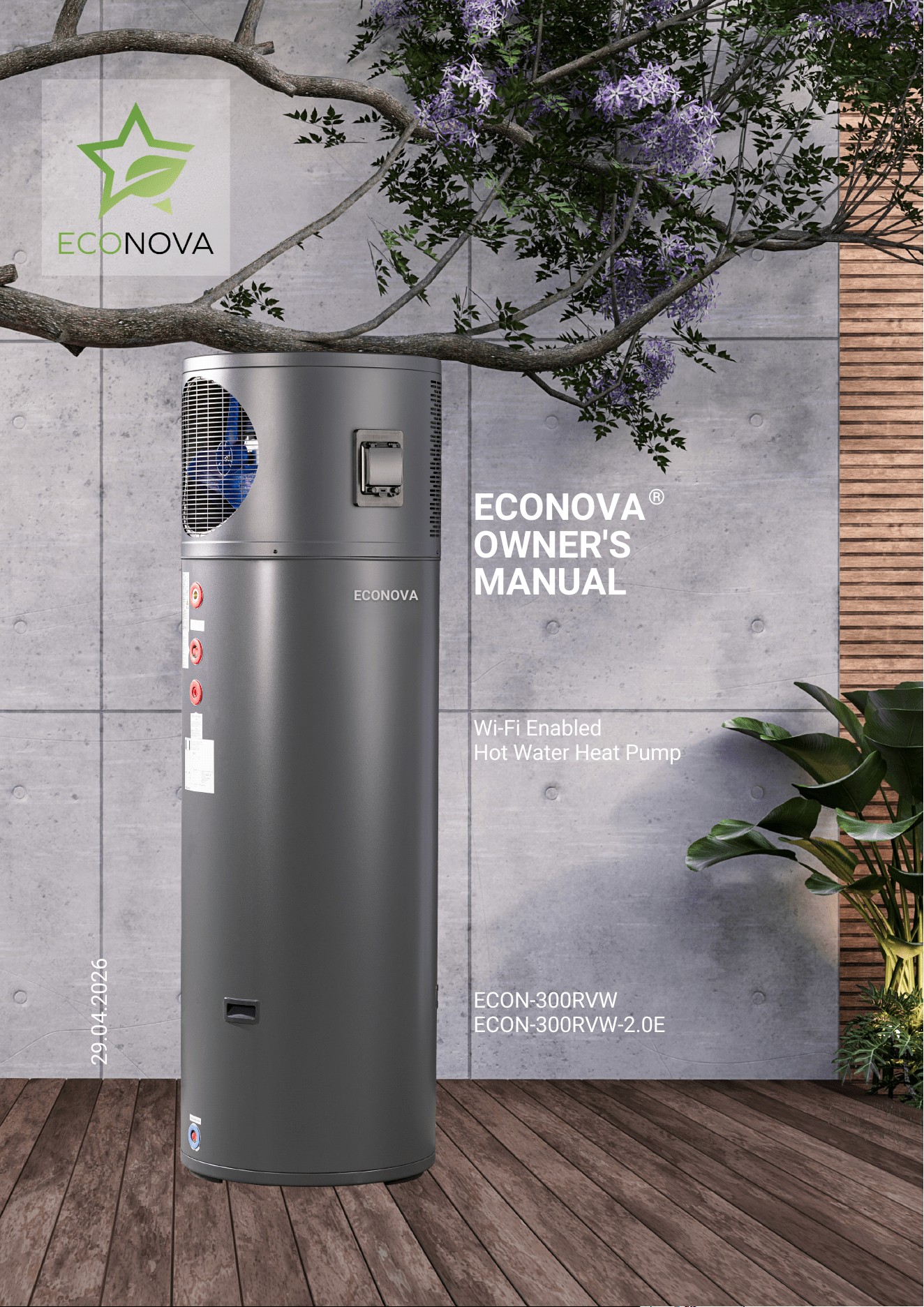
ECON-300RVW
ECON-300RVW-2.0E
ECONOVA
OWNER'S
MANUAL
Wi-Fi Enabled
Hot Water Heat Pump
29.04.2026
®
E
C
O
N
O
V
A
Table of Contents
Installation 16-18
Specifications 5
Owners Operations 6-8
System Maintenance 9-10
Part 2: Installation Instructions 11
Introduction 3
Connections and Dimensions 12
Installer Warnings and Safety Information 13-14
Pre-Installation Information 15
Commissioning 19
Electrical and Controls 20
Connections and Dimensions 2-22
Owners Safety Information 4
System Repairs 23
Warranty 24-25
Congratulations on your purchase of one of the most energy efficient Heat Pump Water Heaters
in the world. Our Australian based design team has over 20 years experience designing and
making some of the most exceptional heat pump water heaters and we are very proud to provide
you with this manual to consider.
All ECONOVA models featured in this manual are mains powered, electrical safety protection Class I, IPX4 rated for
ingress protection, uses flammable refrigerant R290, fixed appliance requiring fixed connection to mains through
an RCBO . The units must be installed by qualified and trained professionals according to local regulations
for plumbing and electrical safety.
This product complies with the Lead Free requirements of the National Construction Code Volume Three, PCA.
Within this manual are instructions required by the safety standards AS/NZS 60335.2.40:2023 and AS/NZS
60335.1:2020+A1 applicable to heat pumps included in the manuals.
Introduction
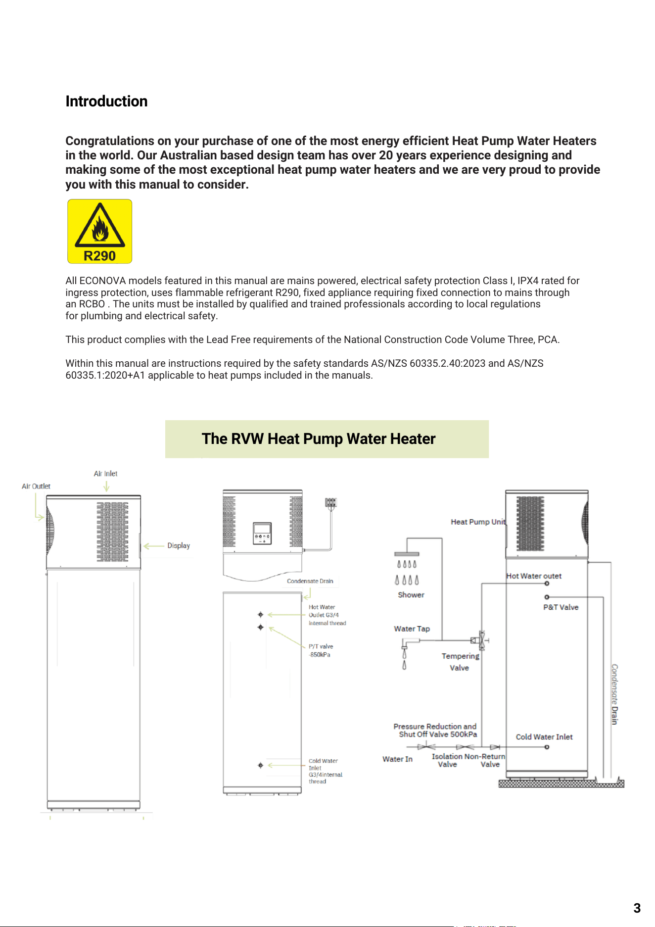
The RVW Heat Pump Water Heater
3
Owners Warning: Safety Information
Children, the disabled and the elderly are at highest risk
of burns. Feel the water temperature with your hands
before showering or taking a bath to avoid burns.
This appliance is not intended for use by persons
(including children) with reduced physical sensory or
mental capabilities, or lack of experience and knowledge,
unless they have been given supervision or instructions
concerning use of the appliance by a person responsible
for their safety.
Children should be supervised by a responsible person to
ensure their safety. We recommend keeping children
away from the Heat Pump.
Do not remove, cover, or damage any permanent
instructions or labels from the exterior or interior of the
unit panel.
Do not puncture the water heater casing, smoke, or
activate sparking of any description within 1.5 meters of
this water heater. R290 may not contain an odour.
Compliance with national gas
regulations should be observed.
This water heater contains flammable
propane refrigeration in a sealed closed
refrigeration circuit.
Under no circumstances should “home craft” type
modifications be attempted. To avoid an electric shock
do not operate the machine with wet hands. If the power
supply cord is damaged, it must be replaced by the
manufacturer, its service agent or similarly qualified
persons to avoid a hazard.
Before cleaning, be sure to stop operation and isolate the
unit (i.e. turn off the isolating switch or circuit breaker),
otherwise, electric shock or injury may occur.
Do not insert fingers, rods or other objects into the air
inlet or outlet. The fan is rotating at high speed, which
may cause injury. Do not use flammable sprays, such as
hairspray or paint near the machine to avoid fire.
The unit must be fixed firmly, otherwise noise and
vibration may be generated. Ensure there are no
obstacles around the device.
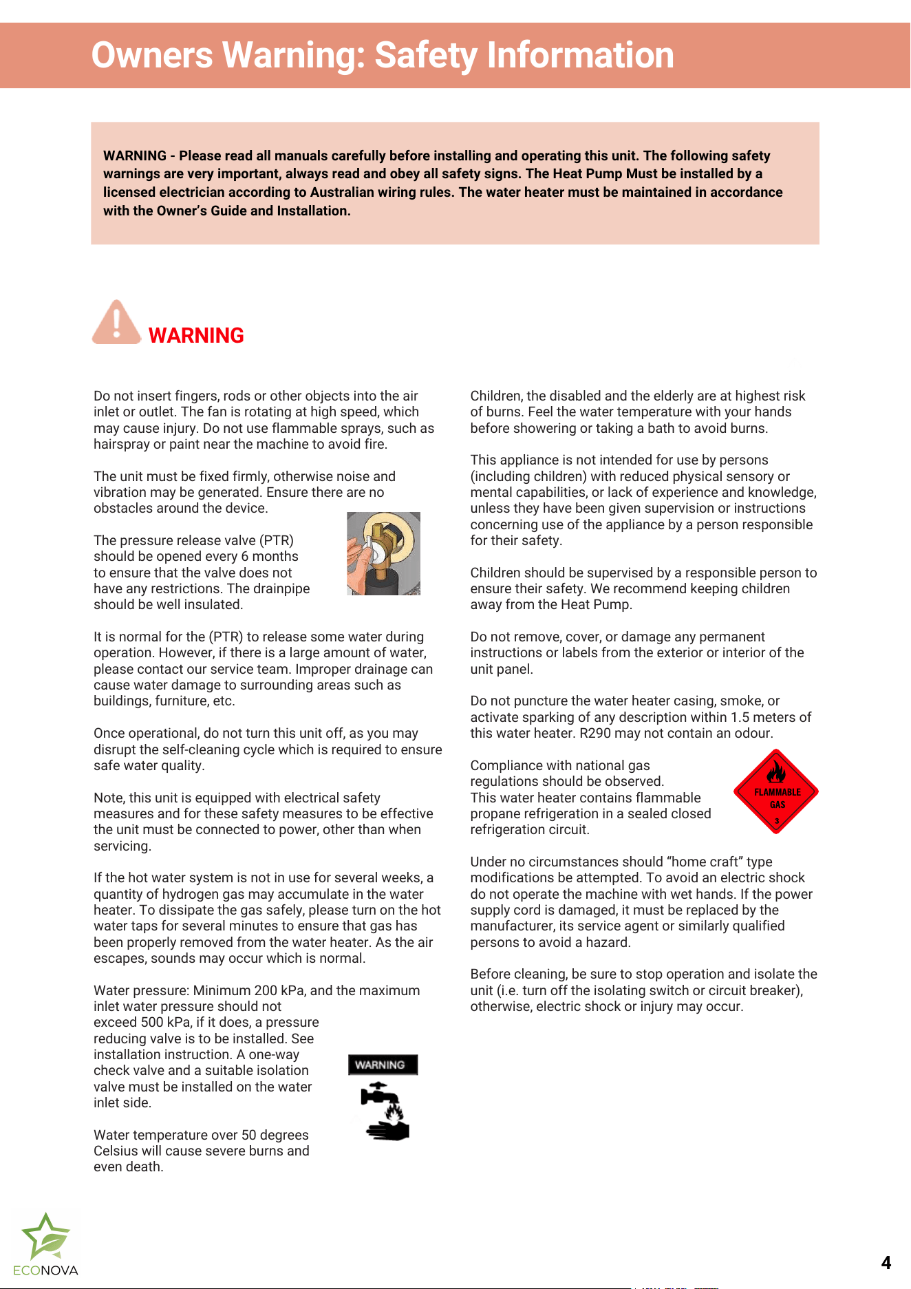
The pressure release valve (PTR)
should be opened every 6 months
to ensure that the valve does not
have any restrictions. The drainpipe
should be well insulated.
It is normal for the (PTR) to release some water during
operation. However, if there is a large amount of water,
please contact our service team. Improper drainage can
cause water damage to surrounding areas such as
buildings, furniture, etc.
Once operational, do not turn this unit off, as you may
disrupt the self-cleaning cycle which is required to ensure
safe water quality.
Note, this unit is equipped with electrical safety
measures and for these safety measures to be effective
the unit must be connected to power, other than when
servicing.
If the hot water system is not in use for several weeks, a
quantity of hydrogen gas may accumulate in the water
heater. To dissipate the gas safely, please turn on the hot
water taps for several minutes to ensure that gas has
been properly removed from the water heater. As the air
escapes, sounds may occur which is normal.
Water pressure: Minimum 200 kPa, and the maximum
inlet water pressure should not
exceed 500 kPa, if it does, a pressure
reducing valve is to be installed. See
installation instruction. A one-way
check valve and a suitable isolation
valve must be installed on the water
inlet side.
Water temperature over 50 degrees
Celsius will cause severe burns and
even death.
WARNING - Please read all manuals carefully before installing and operating this unit. The following safety
warnings are very important, always read and obey all safety signs. The Heat Pump Must be installed by a
licensed electrician according to Australian wiring rules. The water heater must be maintained in accordance
with the Owner’s Guide and Installation.
WARNING
4
2.Installation Safety
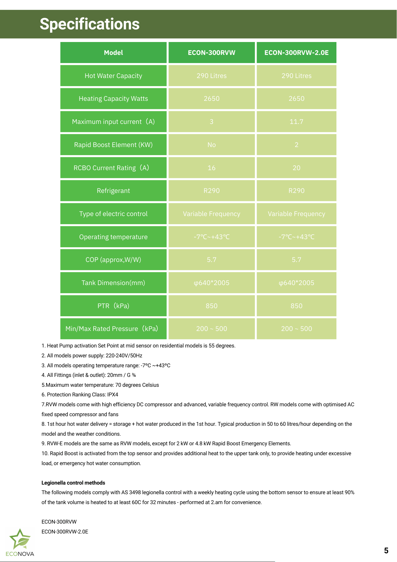
1. Heat Pump activation Set Point at mid sensor on residential models is 55 degrees.
2. All models power supply: 220-240V/50Hz
3. All models operating temperature range: -7ºC ~+43ºC
4. All Fittings (inlet & outlet): 20mm / G ¾
5.Maximum water temperature: 70 degrees Celsius
6. Protection Ranking Class: IPX4
7.RVW models come with high efficiency DC compressor and advanced, variable frequency control. RW models come with optimised AC
fixed speed compressor and fans
8. 1st hour hot water delivery = storage + hot water produced in the 1st hour. Typical production in 50 to 60 litres/hour depending on the
model and the weather conditions.
9. RVW-E models are the same as RVW models, except for 2 kW or 4.8 kW Rapid Boost Emergency Elements.
10. Rapid Boost is activated from the top sensor and provides additional heat to the upper tank only, to provide heating under excessive
load, or emergency hot water consumption.
Legionella control methods
The following models comply with AS 3498 legionella control with a weekly heating cycle using the bottom sensor to ensure at least 90%
of the tank volume is heated to at least 60C for 32 minutes - performed at 2.am for convenience.
ECON-300RVW
ECON-300RVW-2.0E
Specifications
Model
ECON-300RVW
ECON-300RVW-2.0E
Hot Water Capacity
290 Litres
290 Litres
Heating Capacity Watts
2650
2650
Maximum input current
(
A)
3
11.7
Rapid Boost Element (KW)
No
2
RCBO Current Rating
(
A
)
16
20
Refrigerant
R290
R290
Type of electric control
Variable Frequency
Variable Frequency
Operating temperature
-7℃~+43℃
-7℃~+43℃
COP (approx,W/W)
5.7
5.7
Tank Dimension(mm)
φ640*2005
φ640*2005
PTR
(
kPa)
850
850
Min/Max Rated Pressure
(
kPa
)
200 ~ 500
200 ~ 500
5
System Operation
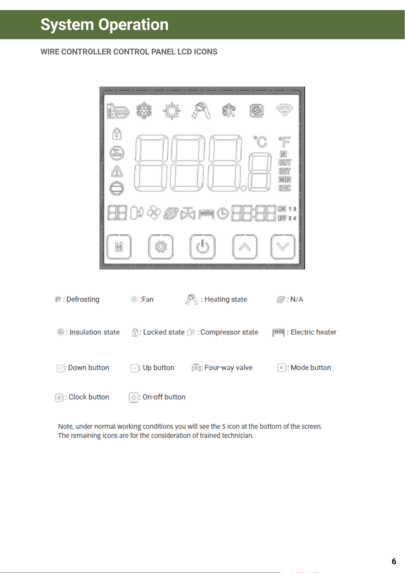
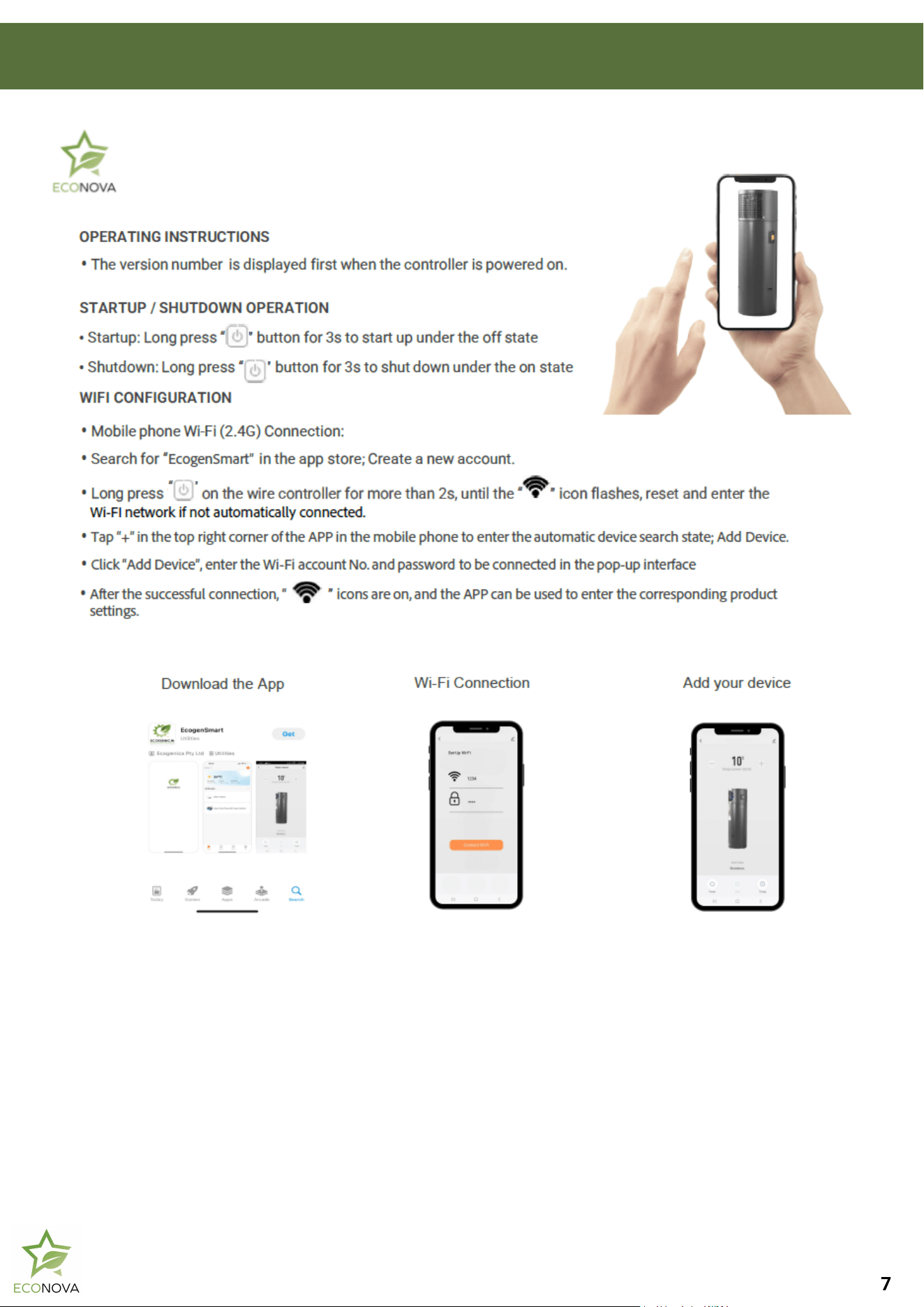
WIRE CONTROLLER CONTROL PANEL LCD ICONS
6
2.Installation Safety
7
2.
2.Installation Safety
8
System Maintenance
Routine Inspection and Maintenance Guidelines
Please inspect the unit regularly for any visible signs of
damage. If any damage is detected, contact our
maintenance team immediately for assistance.
In regions where temperatures fall below 0°C, and if the
system will be inactive for an extended period, it is
essential to drain all water from the tank. This will prevent
potential ice formation inside the cylinder, which can
cause serious damage.
Anode Maintenance
Your water heater is equipped with a sacrificial anode to
protect the cylinder from corrosion. Over time, this anode
will wear out. We recommend replacing the anode during
your five-year service interval—or sooner if you reside in
an area with poor water quality.
Technician Safety and Repair Protocols
All repair work must be conducted under controlled
procedures to minimize risks associated with flammable
gases or vapors during operation.
Technicians and maintenance personnel must be fully
aware of the repair requirements and the working
environment. Avoid conducting work in confined or
sealed spaces. The repair area should be properly
isolated and free from combustible materials to maintain
a safe working condition. Ensure that all technical staff
are aware of the potential for refrigerant gas leaks.
Evaporator Maintenance and Safety Notice
The efficiency of the heat pump is directly affected by the
cleanliness of the evaporator. Dust, mud, or other debris on
the evaporator surface can block airflow, reducing the
effectiveness of heat exchange with the surrounding air. This
results in diminished heating efficiency and increased strain
on the unit.
To maintain optimal performance, customers must ensure
the heat pump remains clean and free from obstructions at
all times.
Important Safety Warning:
**DO NOT USE FLAMMABLE CLEANING PRODUCTS** to
clean your heat pump.
If you notice a buildup of grime or debris on the evaporator,
please **do not attempt to clean it yourself**. Contact
**ECONOVA** to arrange a professional maintenance visit.
Our trained technicians will ensure safe and proper cleaning
to protect your system and uphold warranty conditions.
DRAINING THE TANK
If the tank is to be replaced, ensure the site is appropriate for
safe drainage. Draining can be performed by connecting a
hose to the cold water inlet and running it to a suitable drain
point. To prevent the formation of a partial vacuum during
draining, it is necessary to disconnect the hot water outlet or
open the Pressure and Temperature Relief (PTR) valve.
Ensure that the drain line is positioned to safely discharge
water away from the operator while the valve is open. All
procedures must comply with *AS/NZS 3500.4:2021, Section
5.11*.
REFRIGERATION REPAIRS
All refrigeration leak detection must be performed using
equipment certified for R290 (flammable refrigerant). The leak
detector must be suitable for use with flammable gases and
must not generate sparks.
Prior to beginning work and throughout the process, use an
appropriate detector to check for refrigerant leaks. Only trained
and qualified personnel should carry out any refrigerant
handling or repair tasks.
WARNING – HOT WATER RISK
This appliance may deliver water at high temperatures. Always
refer to the *Plumbing Code of Australia (PCA)*, local
regulations, and the installation instructions to determine
whether additional delivery temperature control is required.
Failure to do so may result in scalding or other safety hazards.
PRESSURE & TEMPERATURE RELIEF (PTR) VALVE
MAINTENANCE
To prevent excessive pressure buildup within the water tank—
which may lead to tank deformation or reduce its service life—
the Pressure and Temperature Relief (PTR) valve must be
maintained in working order.
Locate the PTR valve on the unit. Carefully lift the lever to
manually activate the valve, allowing a small amount of water to
discharge. This process confirms that the valve is functioning
correctly by relieving internal tank pressure as intended.
If water flows freely, the valve is operational. If water does not
discharge or the valve appears stuck or blocked, it may be faulty
and must be replaced immediately.
Homeowner Responsibility
It is strongly recommended that homeowners perform regular
checks on the PTR valve—ideally every six months—as outlined
in AS/NZS 3500.4. Routine activation of the valve helps prevent
mineral build-up and ensures the system remains compliant and
safe.
Failure of the PTR valve to operate correctly can result in
uncontrolled internal pressure, posing significant risk to both the
system and property.
If the valve is not functioning or requires replacement, please
contact your licensed plumber or our Ecogenica service team for
assistance. Only licensed tradespeople should perform
replacements or adjustments to the PTR valve.
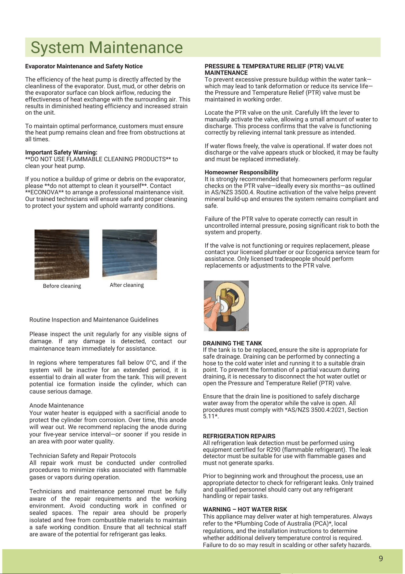
Before cleaning
After cleaning
9
2.Installation Safety
PTR MAINTENANCE
Periodic operation of the valve is recommended to ensure smooth water flow. If the
water does not flow freely, change valve.
To avoid the expansion and deformation of the water tank due to excessive pressure,
the service life of the water tank will be affected.
I. Find the position of the valve.
II. Carefully release the valve with the lever to release some water from the tank.
III. Note: Please use the water discharged from the container to avoid damage to other items.
IV. If the water is flowing, the valve is still in proper working order.
V. If the water does not flow freely, the valve is out of function and needs to be replaced.
VI. If the valve needs to be replaced, please contact your plumber or our service team for further assistance.
CHECK
Please check the machine regularly for any damage, if there is obvious damage, please contact our maintenance team.
In some cold areas (below zero degrees Celsius), if the system stops working for a long time, the water in the water
tank should be released before activating the heat pump, to ensure the water is not freezing.
Failure to do so may cause the machine to malfunction and, in severe cases, damage.
If water does not release from your P&T valve consult your plumber and ECONOVA®.
System Maintenance
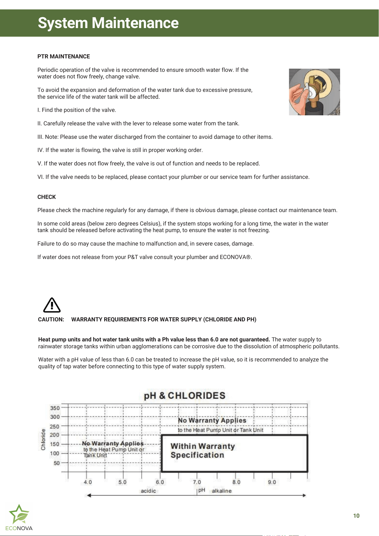
CAUTION: WARRANTY REQUIREMENTS FOR WATER SUPPLY (CHLORIDE AND PH)
Heat pump units and hot water tank units with a Ph value less than 6.0 are not guaranteed. The water supply to
rainwater storage tanks within urban agglomerations can be corrosive due to the dissolution of atmospheric pollutants.
Water with a pH value of less than 6.0 can be treated to increase the pH value, so it is recommended to analyze the
quality of tap water before connecting to this type of water supply system.
10
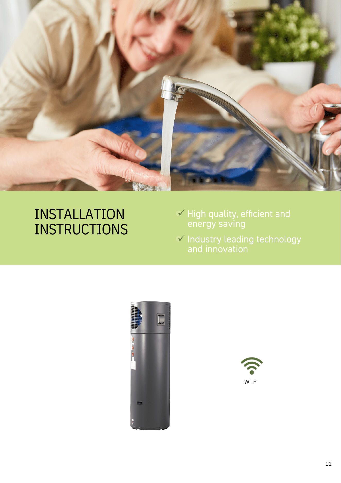
INSTALLATION
INSTRUCTIONS
Wi-Fi
11
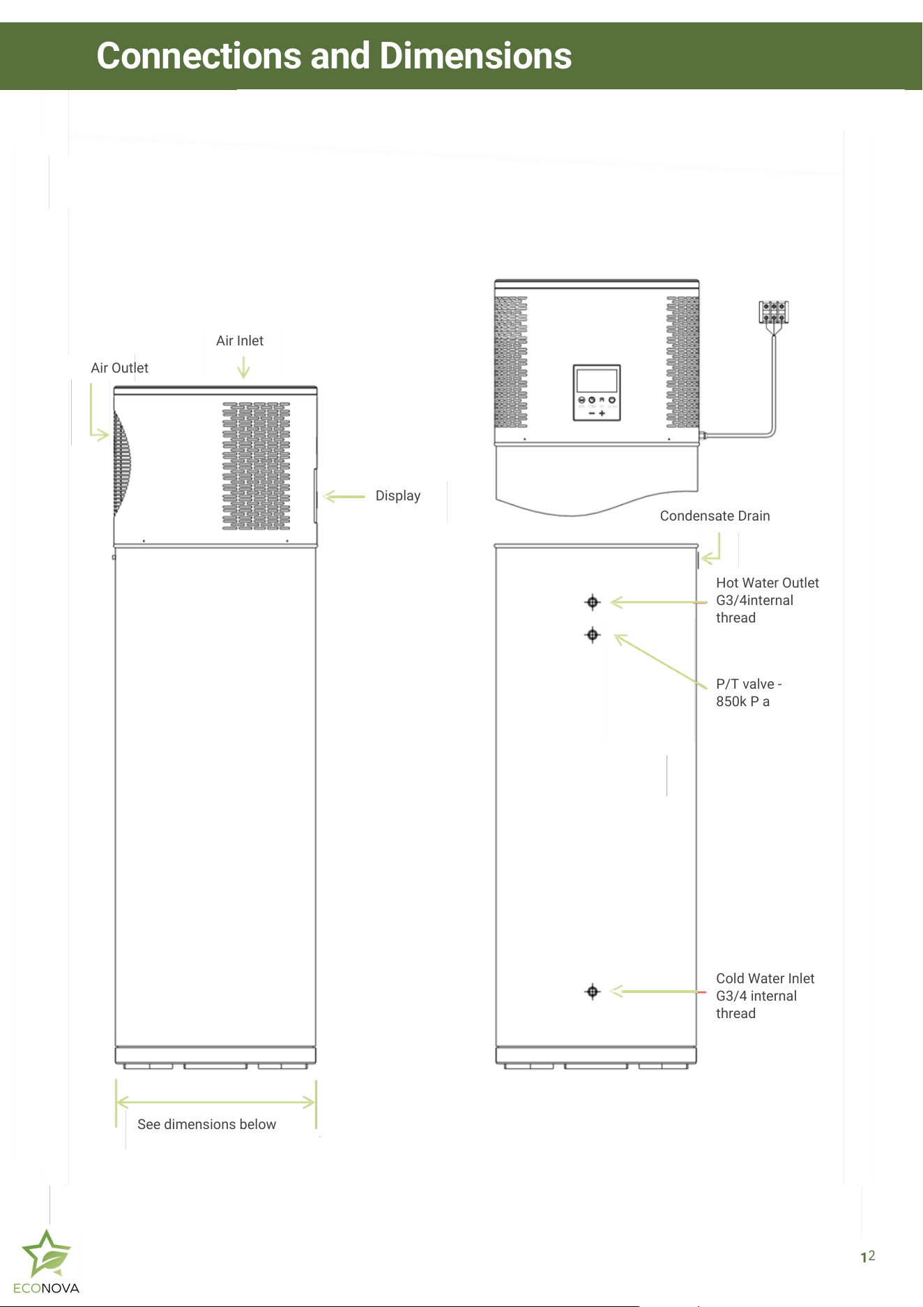
Air Outlet
Air Inlet
See dimensions below
Display
Condensate Drain
P/T valve -
850k P a
Cold Water Inlet
G3/4 internal
thread
Hot Water Outlet
G3/4internal
thread
1
2
Connections and Dimensions
DISPOSAL
Your heat pump contains electrical com ponents. If
electrical appliances are disposed of in landfills or
dump sites, hazardous substances can seep into
groundwater and cause health problems. Please note,
the tank and heat pump must have the R290 natural gas
released, or removed, before the units are sent to metal
recycling, or to your local council appliance recycling
centre. Note, ECONOVA® maintain a metal re-cycling
service.
PLUMBING
Care must be taken to ensure the system is installed in
accordance with AS/NZS 2712 and to AS/NZS
60335.2.40:2019 - with household and similar electrical
appliances.
Since heat pump water heaters can generate water
temperatures more than +50 degrees Celsius,
regulations require that a regulating valve be installed on
the hot water outlet line of the water heater to prevent
the water temperature from exceeding a pre-set safety
upper limit.
The installation must conform with the Plumbing Code
of Australia (PCA), regulations of the local authority, in
line with national building regulations and local
occupational health and safety regulations.
Only licensed professionals will issue a certificate of
compliance, certifying that the work in question meets
all relevant standards, and only licensed professionals
will take out craft insurance.
Ensure that the heat pump unit is installed in a
compliant and accessible location is crucial for
maintaining its warranty and ensuring efficient service.
Please refer to the installation guidelines in this manual
for detailed information on compliant installation
practices.
CUSTOM INSTALLATION
Please consult with ECONOVA® about internal
installations. If a safety tray is required to prevent
building damage, construction, installation and draining
of a safe tray must comply with AS/NZS 3500.4 and all
local codes and regulatory authority requirements.
CONDENSATION DRAIN
Plumbing must be well insulated. Lagging must be applied to pipes and valves for at least the first 500mm
in all directions, including PTR drainpipes. Customer should consider investing in best practice plumbing to
have external hot water pipework to the primary kitchen sink lagged. As every home is different pipework
plumbing insulation in the home is quoted separately.
All installations of ECONOVA® Heat Pump systems must comply with the AS3000 electrical standards. It is
the responsibility of the licensed electrician to ensure that all wiring, power supply connections, and
protective devices adhere to these regulations to guarantee safe and effective operation.
CIRCUIT BREAKER
The hot water pump power supply must be protected by a
separate RCBO on the main power switchboard, if the unit
has an electric element, and it must be rated to suit the
size of the components.
Models with electric booster elements MUST be installed
on their own dedicated circuit to avoid overloading and
ensure proper operation. Models without an element can
be installed on a shared circuit. However, care must be
taken by the licensed electrician to ensure that the shared
circuit is not overloaded.
The RCBO must be incorporated into the fixed wiring in
accordance with the wiring rules and regulations (AS/NZS
3000 -Australian wiring rules).
P&T VALUE DRAIN LINE
A drain line from a relief valve must comply with the
requirements of AS/NZS 3500.4. The outlet of a drain
line must be easily seen, and arranged so discharge
will not cause injury, damage, or nuisance. Drain some
of the water heater must be directed away from the
building, fall continuously, discharge water away from
the operator during the operation of the valve and PTR
drains must use copper piping.
GROUND CONNECTIONS
Proper ground connection is essential. The presence of
water in the piping and water heater does no t provide
sufficient conduction for a ground. Non-metallic
piping, dielectric unions, flexible connector s plumbing
etc, can cause the water heater to be electrically isolated
The heat pump must be installed on a flat dry surface. If there
is no special drainage pipe (sink), be sure to ensure that the
condensed water flowing on the ground can be drained
smoothly to avoid water pooling around the heat pump. As
condensate will otherwise drip from the appliance onto the
floor if the drainpipe is not added.
Installers Warning and Safety Information
13
Do not operate this Heat Pump without a full tank of water
Installers Warning and Safety Information
14
INSTALLATION CHECK LIST
WARNING – This appliance may deliver water at high temperature. Refer to the
Plumbing Code of Australia (PCA), local regulations, and the installation
instructions to determine if additional delivery temperature control (such as
tempering valves) is required.
This system contains flammable R290 refrigerant-grade propane. All service and
installation work must strictly adhere to the safety guidelines outlined in this
manual. If repairs are to be conducted on-site, prior written approval must be
obtained from ECONOVA®. Fire risk management procedures must be followed at
all times.
Important Installation Notes:
- This appliance is intended for direct connection to a mains water supply. It is not
suitable for use with temporary or hose-style connections.
- Electrical installation must comply with AS/NZS 60335.1:2020 and Amendment
1:2021 – Household and Similar Electrical Appliances – Safety General
Requirements.
- All fixed wiring insulation must be adequately protected using appropriately rated
sleeving or other approved means.
- Installation must only be carried out by qualified personnel in compliance with
local, state, and national regulations.
- Improper installation may lead to water leaks, electric shock, fire hazards, or
personal injury.
- Do not use incorrectly rated fuses, as this may result in malfunction or electrical
fire.
- Ensure the grounding electrode is properly and securely connected.
- All electrical plugs and sockets must be dry and tightly fitted. Reliable earthing of
the unit is mandatory.
- The unit must be fully filled with water before being powered on. Activating the
system without water may cause irreversible damage and void the warranty.
- Models with electric booster elements must be installed on their own dedicated
circuit to prevent overloading and ensure correct operation.
- Models without electric boosters may be installed on a shared circuit, but the
licensed electrician must ensure that total circuit load remains within safe limits.
APPLIANCE OPERATION
In case of possible direct exposure to strong wind, face
the air outlet to the most protected area. The direct
incidence of strong wind in the outlet grille during long
periods may affect the performance of the heat pump
increasing the heating times and the frequency of
defrost cycles.
This water heater should not be installed in an area
with a corrosive atmosphere where chemicals or
flammable liquids are stored or where aerosol
propellants are released.
BOOST CONTROL
Some ECONOVA® models contain an electric element
(see Product Specifications) for Automatic boost
control, which will activate the heating element in
extreme usage or temperature circumstances. This
control is built into the PCB and is not controllable
from the control panel. Boost is automatic and does
not adjustment.
INLET-OUTLET CONNECTIONS
Installation of the water inlet or outlet pipes: The water
inlet and outlet thread are ¾ BSP (internal thread).
Pipes must be heat resistant, durable and UV resistant
(when doing outdoor installation). Installation of the
pipe for PTR valve: The specification of the valve
thread is ½ BSP (internal thread). Note: one way valve
must be installed at the inlet.
PRE-INSTALLATION
Ensure that there is enough space for installation and
future maintenance. Do not install the heat pump in an
area that is not easily accessible for maintenance and
repair work. This includes installations in confined
spaces, locations requiring special equipment to
access, or areas that pose a safety risk to our
technicians.
The air inlet and outlet should be free of obstacles and
strong winds.
The bottom surface should be flat and capable of
bearing the weight of the heat pump,
ensuring that no noise and/or vibration results
from poorly installed tank.
POWER REQUIREMENTS
Check the markings on the rating plate of the water heater
to be certain the available power supply corresponds to the
water heater requirements. The Heat Pump Water Heater
must be directly connected to a 230V-240VAC 50Hz mains
power supply.
The water heater Heat Pump must be installed on separate
individual circuits with a breaker switch installed directly at
the switchboard.
Fill the heat pump tank with water before starting the heat
pump for the first time.
SOLAR POWER
Some ECONOVA® models come with Wi-Fi; and all models
have timer activation to better align operation with Solar
Power production. Solar Power must be provided to the
inverter and switch board, as per local regulations and Solar
installation Standards. The timer ensures that the Heat
Pump operates between daylight hours, to align with Solar
Power production.
Solar Power is limited during rainy days, and in the
Winter Months, and hot water loads increase, so we
recommend that timer activations are not used during
these times. Note, the ECONOVA® heat pump will
mostly operate during the day in the Auto Mode if people
show in the morning.
SITE REQUIREMENTS
The running noise and the exhausted airflow should not
affect other people. Take care to consider the location of
bedrooms and noise sensitive areas.
Unsafe Installation location: Installation must comply with
safety standards and regulations. Including, and not limited
to, areas with inadequate ventilation, proximity to
hazardous materials, or installations that violate
manufacturer guidelines.
Do not install in areas with pH & chlorides outside the range
listed here (pH 6 to 10) & Chloride >200):
Installations indoors are not recommended,
and permission must be secured from
ECONOVA®.
Ensure the site is suitable for draining the tank at some
point. Draining of the tank can be accomplished by the
connection of a hose to the cold-water inlet and running to
a suitable drain. It will be necessary to disconnect the hot
water outlet or PTR valve to relieve any partial vacuum
created as the water flows out.
while
When installing the tank DO NOT use adhesives since
they are not considered to be a reliable fixing means.
15
Pre-Installation Safety Information
PIPING CONNECTIONS
The water inlet and outlet thread are 3/4 BSP (internal
thread). Pipes must be heat resistant, durable and UV
resistant (when doing outdoor installation). Installation of
the pipe for PTR valve: The valve thread specification is ½
BSP (internal thread). Note: non-return valve must be
installed at the inlet.
The temperature and pressure-relive valve must
beinstalled according to local code. Not doing so will
cause damage to the appliance and to other property.
The function of the temperature and pressure relief valve
once installed on this water heater is to discharge high
conditions. Therefore, it is strongly recommended thatt he
pipe work connected to the relief valve can withstand water
temperatures exceeding 99˚C. Failure to follow this
recommendation may result in a dangerous situation.
DIELECTRIC JOINT
The dielectric joint will basically avoid any physical contact
between the two metals, acting as an effective insulator
and prevent this attack. How quickly this, or it at all,
happens, depends a lot on the content of your water. It’s
pH, the dissolved minerals and the metals involved.
Never block or seal the outlet of the PTR
valve or its drain for any reason. The
warranty will be void if the relief vale or
other safety devices are tampered with or if
the installation is not in accordance with
this manual.
CONDENSATE DRAIN TUBES
This unit has an integrated condensation tray. The water
collected in the tray drains out of the tube. It is
important that a hose is attached to drain. Ensure the
heat pump is on a flat, firm surface capable of bearing
the weight of the device. If there is no special drainage
pipe (sink), be sure to ensure that the condensed water
flowing on the ground can be drained smoothly to avoid
water pooling around the heat pump. As condensate will
otherwise drip from the appliance onto the floor if the
drainpipe is not added.
All pipe work should be insulated with proper insulating
material (weatherproof and UV resistant if exposed) to
optimise energy efficiency.
To ensure the faultless operation, the unit must be
installed vertically without a significant tilt, minor tilts
should be in the direction of the condensate drain to
favor the condensates drainage.
Take care to consider the location of bedrooms and noise
sensitive areas. The running noise and the exhausted
airflow should not affect other people.
The inlet and outlet should be free of obstacles and strong
winds.
Installation must comply with safety standards and
regulations. Including, and not limited to, areas with
inadequate ventilation, proximity to hazardous materials,
or installations that violate manufacturer guidelines.
16
Different metals between plumbing and tank materials and
additionally the effect of hot water can cause the corrosion
of one of the metals (generally the one in the tank is the
metal attacked).
Installation
THERMAL EXPANSION TANK
The pressure rating of the relief valve
must not exceed 850kPa, the maximum
working pressure of the water heater as
marked on the rating plate! Proper
ground connection is essential!
TEMPERATURE MIXING DEVICE
The PCA (Plumbing Code of Australia), AS/NZS3500.4 ;
requires the installation of a temperature limiting devic e
between the water heater and the hot water outlets in a
bathroom or similar usage point to reduce the risk of
scalding.
The maximum temperature that can be delivere d is 50
degrees Celsius. Additionally, a certified plumber may
have the legal obligation to ensure the water heater
installation meets the hot water delivery requirements
listed in AS/NZS3500.4.
POWER SUPPLY AND ELECTRICAL INSTALLATION
REQUIREMENTS
EXPANSION CONTROL DEVICE
Thermal expansion is a natural process where heated
water increases its volume. When this water is stored in
a tank, this volume increase will in fact mean a pressure
is increased in the tank. This pressure increase
potentially can result in a dangerous situation if
Pressure Relief Valves are not releasing water
occasionally. Consequently, when the safety settings on
the relief valve are reached, the relief valve will operate
during the heating cycle. Please contact a licensed
professional, water supplier or plumbing inspector for
information about this subject.
A temperature and pressure relief valve are supplied
and must be installed in the tank port marked for this
purpose. No valve or accessory of any type should be
installed between the relief valve and the tank. Please
observe local codes for the correct installation of relief
valves.
The kW rating of the relief valve must be higher than
6kW to ensure that is always above the maximum
output power of the water heater when operating with
both electrical heated and heat pump and air at 40˚c.
The supplied PTR valve complies with this by having a
power capacity of 10kW.
Connect the outlet of the relief valve to a suitable open
drain so that the discharge water cannot contact any
electrical parts, persons or animals and to eliminate
any other possible risks. Always use a valve of the
same rated pressure and temperature as the PTR valve
supplied with the unit.
A saturation index greater than +0.4 or in corrosive
wate r areas where there is enough silica dissolved in
the wate r may require the installation of an expansion
control valve (ECV) in the cold-water line, being the
last valveinstalled prior to the water heater.
PTR VALVE
17
Installation
Before installation, verify that the available power supply
matches the specifications listed on the rating plate of
the heat pump water heater. The unit must be connected
to a 230–240V AC, 50Hz mains power supply.
The heat pump water heater must be installed on a
dedicated individual circuit protected by an RCBO
(Residual Current Breaker with Overload protection)
located at the main switchboard. An effective and
reliable earth connection is required for safe operation—
ensure the ground wire is securely connected to the
external grounding system.
All power wiring should be laid out neatly and securely,
avoiding splicing of wires wherever possible. Electrical
connections must comply with all relevant safety
regulations and wiring standards.
Important: The unit must only be powered on after the
tank has been completely filled with water.
Wi-Fi Setup:
To enable smart control, download the companion app
and pair your heat pump to your device following the
application instructions.
Solar and Off-Grid Use:
- In warmer months, the heat pump can be set to operate
between 10:00 AM and 5:00 PM using the timer function
for optimal use of solar power.
- During colder months, we recommend using Auto Mode
without a timer to ensure consistent hot water
availability.
- For off-grid installations, ensure the system is
connected to a UPS (Uninterruptible Power Supply) with
a 230–240V AC, 50Hz true sine wave output.
Circuit Protection:
To ensure uninterrupted operation, the hot water heat
pump must be protected by a dedicated RCBO rated
appropriately for the installed components. Do not
connect any other appliances—especially high-power
devices—to the same power supply circuit as the water
heater.
Installation
CLEARANCE REQUIREMENTS
To ensure proper operation and serviceability, the following minimum clearances must be maintained:
A minimum of 300 mm clearance must be provided on both sides of the heat pump, at the air inlet and outlet, to
allow for adequate airflow.
An overhead clearance of 300–400 mm must be maintained above the unit to allow for future access if servicing is
required.
Failure to maintain these clearances may impact system performance and access for maintenance.
18
19
Before the heat is started please make sure the tank is full of water!
Then please consider this safety check list.
INSTALLATION AND COMMISSIONING CHECK LIST:
1. P&T and condensate drain lines must be directed away from building footings and must
continuously fall from the valve to the point of discharge. Ensure the discharge does not pose a
risk of injury to persons.
2. The drain line must discharge water away from the operator during valve operation.
Installation must comply with AS/NZS 3500.4:2021, Section 5.11.
3. Copper piping must be used for all drain lines. Plastic piping is not permitted.
4. All drain lines must be insulated for a minimum of the first 500mm from the valve outlet.
5. Please note that these drain lines are considered "outlets" in accordance with AS/NZS
3500.4:2021, Clause 2.5.2.
6. Before commissioning the appliance, ensure the storage tank is completely filled with water.
Purge the tank by opening the hot water outlet and one or more hot water taps to remove air
from the system.
7. Open the cold water inlet valve to begin filling the tank.
8. Close the hot water taps only once the water flow is steady and free of air pockets.
9. Close the valve after a few moments, once water is flowing smoothly without air bubbles.
10. Connect the appliance to the power supply using fixed wiring, including an earth conductor.
Ensure connections meet all local electrical codes.
11. After verifying that the power cord is securely connected, switch on the water heater.
12. There is no need to manually activate the display—it will power on by default.
13. The unit features a three-minute delay start function. Please be patient. After 30 minutes of
operation, verify the system status. If any issues occur, check the display screen for fault codes.
14. The ECONOVA® unit has fully automatic control and will operate based on environmental
conditions, heating the stored water to the factory-set temperature.
Commissioning
Wire controller
Water tank temperature
Compressor
Ambient
temperature Exhaust
temperature
Suction temperature
Coil temperature
Water tank bottom temperature
Fan high output
Fan low output
Joint control switch
Four-way valve
Transformer
Transformer
N
/
A
Low-voltage switch
High-voltage switch
Water flow switch
Electronic expansion valve
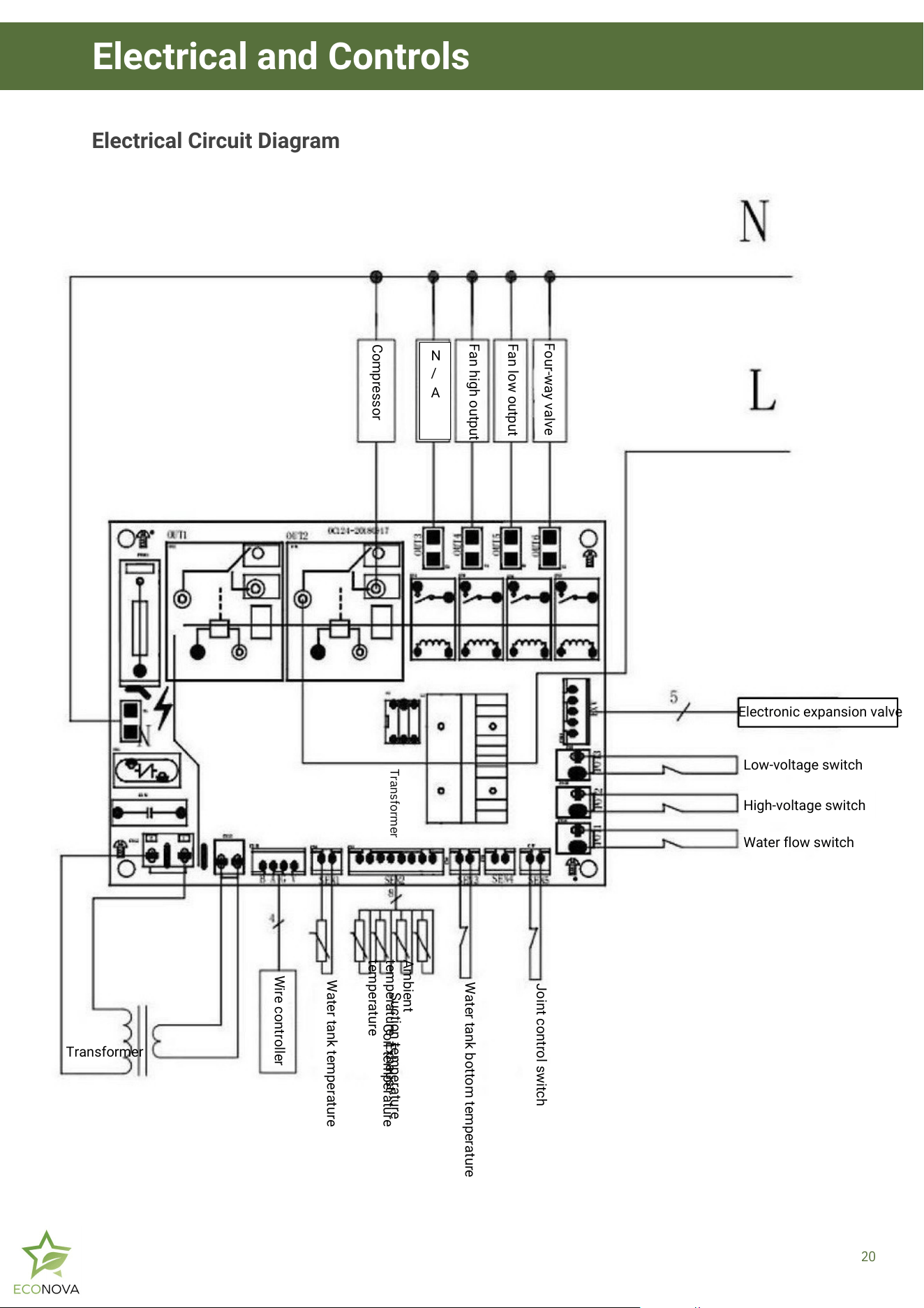
Electrical Circuit Diagram
20
Electrical and Controls
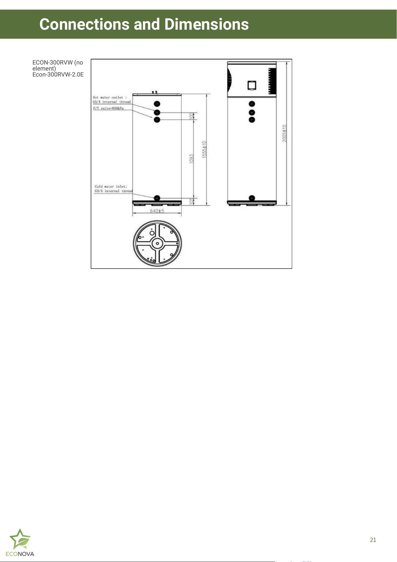
ECON-300RVW (no
element)
Econ-300RVW-2.0E
21
Connections and Dimensions
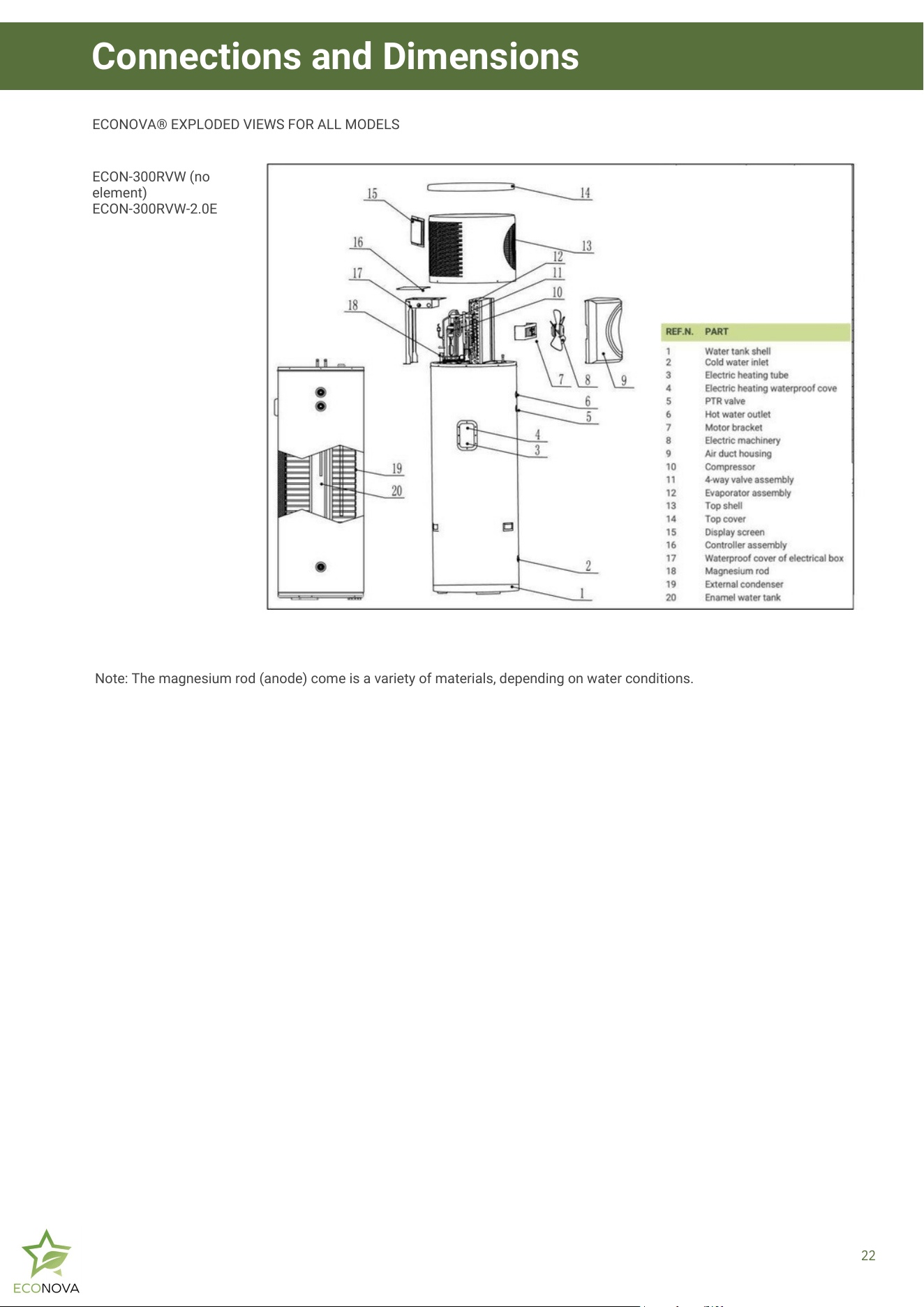
ECON-300RVW (no
element)
ECON-300RVW-2.0E
ECONOVA® EXPLODED VIEWS FOR ALL MODELS
Note: The magnesium rod (anode) come is a variety of materials, depending on water conditions.
22
Connections and Dimensions
System Repairs
1.
5.
2.
3.
4.
9.
6.
7.
8.
11.
10.
NOTE; REPAIR PROCEDURE: ECONOVA® normally return heat pumps if repairs are to be conducted. If repairs are to
be completed on site, approval from ECONOVA® must be obtained in writing, and this repair procedures must be
followed to ensure fire risks are managed with best practices implemented.
Carry out repair work under controlled procedures to ensure the lowest risk by flammable gases or vapours
arising during the operation.
All repair technicians and maintenance personnel in the work area shall be aware of the nature of the job.
Do not operate in the sealed space.
Working area should be properly isolated to control combustible material to ensure a safe working
condition.
Flammable refrigerant pipe related work can only be conducted when R290 gases are removed from the
site.
Ventilation is essential. Make sure the work area is adequately ventilated before opening the system.
Remove the R290 before disposal or hot gas service work.
Make sure the site has enough ventilation to ensure the leaking refrigerant is release into the atmosphere
safely and rapidly.
During transport, installation or use, please be careful not to damage any of the heat pumps refrigeration
circuit. Sparks may result in explosion, fire or burning.
The electrical equipment should not be placed under the unit or where refrigerant could gather in the event
of a leak.
If the tank is to be removed, ensure that hot water is drained safely into drains and away from building
structure, people, walk ways and the ECONOVA® Heat Pump.
REPAIR CHECK LIST:
23
Disclaimer: All our Heat Pump systems must be installed by a licensed and certified installer ensuring all local, state
and national regulations are met. Failure to do so will void this warranty.
24
Warranty
NOTICE TO CONSUMER
Our goods come with guarantees that cannot be
excluded under the Australian Consumer Law. You are
entitled to a replacement or refund for a major failure and
compensation for any other reasonably foreseeable loss
or damage. You are also entitled to have the goods
repaired or replaced if the goods fail to be of acceptable
quality and the failure does not amount to a major failure.
Note: We recommend all consumers safely store
receipts, invoices, warranties and any installation records
to allow for faster processing of warranty claims.
TERMS OF WARRANTY
ECONOVA® PRODUCTS
The warranty terms, detailed here, relate only to the
following ECONOVA® ranges: RVW, RVW-2.0E, FREC-W,
FREC-WR, SV-4.2EC.
The warranty period is as follows from the date of
installation:
Hot Water Heat Pump All-In-One Systems: A five (5) year
warranty applies to the Hot Water Heat Pump All-In-One
System supplied and a two (2) year warranty for labour
and ancillary components/parts. Ancillary
components/parts covered under the 2-year warranty
include items such as the Pressure Temperature Relief
Valve, Tempering Valve, Isolation Valve, Pressure
Limiting Valve, General Power Outlet, and 3-pin plug.
Hot Water Heat Pump Split Systems: A seven (7) year
warranty applies to the tank, a five (5) year warranty to
the rest of the Hot Water Heat Pump Split System and a
two (2) year warranty for labour and ancillary
components/parts. Ancillary components/parts covered
under the 2-year warranty include items such as the
Pressure Temperature Relief Valve, Tempering Valve,
Isolation Valve, Pressure Limiting Valve, General Power
Outlet, and 3-pin plug.
Additional warranty for Solar Victoria Customers
For Econova Hot Water Systems installed from the 1st
September 2025, under the Solar Victoria Solar Homes
Program, an enhanced warranty applies in accordance
with the program requirements:
A five (5) year warranty applies to all parts and labour for
the complete hot water system, commencing from the
date of installation.
This coverage is in addition to the standard warranty
terms outlined in this document and is provided
specifically for Solar Victoria program customers.
All other conditions, exclusions, and requirements
contained in this warranty remain in force. Proof of
installation under the Solar Victoria Solar Homes
Program must be provided to claim this enhanced
coverage.
The benefits conferred by this Warranty are in addition to
all other rights and remedies in respect of the Heat Pump
Water Heater System, which the purchaser has under the
law including the Competition and Consumer Act 2010
and consumer protection legislation of the States and
Territories. Nothing in this Warranty has the effect of
excluding, restricting or modifying those rights.
ECONOVA® will repair or provide parts for repair or
replacement, where defects arise from faulty materials.
ECONOVA® is responsible for reasonable costs
associated with legitimate warranty claims, as
determined by ECONOVA®. To determine whether a
warranty claim is legitimate, ECONOVA® may send an
ECONOVA® accredited service agent to inspect the
product. ECONOVA® is not responsible for:
a. any costs that are not pre-approved in writing by
ECONOVA®; and
b. any costs associated with a product which is
determined upon inspection not to be covered by this
warranty.
Any reasonable costs incurred by the consumer that are
associated with making a legitimate warranty claim will
be reimbursed by ECONOVA®.
Enquiries relating to warranty coverage and claims for
ECONOVA® products or services must be made by
contacting ECONOVA®. An ECONOVA® accredited
service agent or the ECONOVA® service department can
repair or replace product components, subject to
ECONOVA® terms and conditions of warranty.
ECONOVA® can, in addition, provide information on
operation and maintenance of ECONOVA® products.
ECONOVA® contact details are on the back of this
document.
WARRANTY CONDITIONS
The person making the claim must be the owner of the
Product or have written authorisation to act on behalf of
the owner which must be provided to ECONOVA®.
The person making the claim must notify ECONOVA® as
soon as they notice any defects without delay, and the
product must be within its warranty period as set out in
the terms of warranty.
The warranty applies to products manufactured on or
after the date of publication of this warranty.
The terms of warranty take effect from the date of
completion of installation of the Product and full
payment of the Product. ECONOVA® reserves the right
to request proof of purchase or a copy of the certificate
of compliance (this is required by law to be issued by the
installer) to verify the date of completion of installation
prior to commencing any warranty work. Where the date
of completion of installation is not known, then this
warranty will commence 2 months after the date of
manufacture. The date of manufacture is stated on the
data plate of the appliance.
Prior to any inspection, service, repair or replacement
undertaken pursuant to the warranty on a Heat Pump
Water Heater System, the following must occur:
a. The warranty works must be authorised by
ECONOVA®; and
b. Proof of purchase and the certificate of compliance
must be submitted to ECONOVA®.
The Heat Pump Water Heater System must be installed,
commissioned, serviced, repaired and removed in
accordance with the installation instructions supplied by
ECONOVA® for the Heat Pump Water Heater System,
and in accordance with all relevant statutory and local
requirements of the state/province/municipality in which
the Heat Pump Water Heater System is installed.
All Heat Pump Water Heater Systems must be operated
and maintained in accordance with the ECONOVA®
operating instructions.
25
Warranty
The warranty only applies to the Heat Pump Water
Heater System and original or genuine (company)
component replacement parts provided by ECONOVA®.
The warranty does not cover any plumbing or electrical
parts supplied by the installer and that is not an integral
part of the Heat Pump Water Heater System. Such parts
would include, but are not limited to, pressure regulating
valve, limiting valves, check valves, tempering valves,
electrical switches or fuses.
To the extent permitted by law, ECONOVA® shall not be
liable under this Warranty for any consequential loss or
damage or any incidental expenses resulting from any
breach of this warranty, including but not limited to,
claims for damage to buildings, roofs, ceilings, walls,
foundations, gardens, personal belongings or household
effects, fixtures and fittings, or any other consequential
loss, damage or inconvenience, either directly or
indirectly due to the Heat Pump Water Heater System or
component(s) related to the system or its operation
including but not limited to leakage.
Where a failed component or Heat Pump Water Heater
System is replaced under warranty, the balance of the
original warranty period will remain effective. The
replaced part or Heat Pump Water Heater System does
not carry a new warranty.
ECONOVA® reserve the right to have the installed
product returned to the factory for inspection.
Products eligible for repair may be replaced by
refurbished goods of same type rather than being
repaired. Refurbished parts may be used to
repair/replace the Products.
Where the Heat Pump Water Heater System is not
installed in accordance with the installation instructions
or installed in a position that does not allow safe, ready
access as determined by the attending service person,
the service may be refused at their discretion. Any cost
to access the site safely, including the cost of additional
materials, handling and/or safety equipment, will be
charged to the consumer and will be the consumer’s
responsibility.
The Heat Pump Water Heater System must be sized to
supply the hot water demand in accordance with the
guidelines in the Heat Pump Water Heater System
Literature.
WARRANTY EXCLUSIONS
Products supplied by ECONOVA® are subject to
warranties that cannot be excluded by law. Any breach of
condition or warranty is limited to the repair or
replacement of the Product, the supply of an equivalent
Product, the payment of the cost of repairing or replacing
the Product or acquiring an equivalent as determined by
ECONOVA®.
Repair and replacement work will be carried out as set
out in the Heat Pump Water Heater System terms of
warranty. However, the following exclusions may void the
warranty and may incur additional service charges
and/or cost of parts:
Damage to the Heat Pump Water Heater System or any
component, including accidental damage, natural
disasters, acts of God, storm damage, vandalism.
Failure due to abuse, misuse or neglect, improper
maintenance or failure to maintain and incorrect or
unauthorised installations.
Failure or damage caused by alterations, service or repair
work carried out by persons other than ECONOVA®
accredited service agents or the ECONOVA® service
department.
Where no fault is found with the Heat Pump Water Heater
System or its components and the issue is related to the
plumbing installation or is due to a direct or indirect
failure of water, electric or gas supplies, corrosive
atmosphere or other issues not caused by a fault of the
Product including but not limited to:
a. excessive discharge from the temperature and/or the
pressure relief valve due to high water pressure;
b. excessive water pressure;
c. no flow of hot water;
d. water leakage;
e. where the supply of electricity or water does not
comply with relevant codes or acts or the power supply is
cut;
f. the overflow vent drain has not been installed or it is
blocked or corroded;
g. rust due to a corrosive atmosphere.
Where the unit fails to operate or fails because of
excessive cold or ice formation in the piping to or from
the Heat Pump Water Heater System.
Where any faults arise from connecting to a water source
that is unfiltered such as dams, bores, rivers etc.
The Heat Pump Water Heater System being relocated
from its original point of installation.
Operating the water heater and components when not
completely filled with water.
This warranty applies to Heat Pump Water Heater
Systems connected to the energy source listed on the
data label of the Product.
This warranty does not apply to damage caused by
sludge and/or sediment in the water supply.
Repair and/or replacement of the Heat Pump Water
Heater System due to scale formation above 200ppm
(water hardness) in the waterways or the effects of either
corrosive water or water with a high chloride or low PH
level when the water heater.
Where the ECONOVA® Heat Pump Water Heater System
is in a position that does not comply with the Heat Pump
Water Heater System installation instructions or relevant
statutory requirements, causing the need to dismantle or
remove cupboards, doors or walls, or require the use of
special equipment to bring the Heat Pump Water Heater
System to floor or ground level or to a serviceable
position.
Labour costs incurred due to an ECONOVA® accredited
service agent performing checks which should have been
carried out by the consumer in accordance with the
operating instructions and where no defect is found.
Disclaimer: Our Heat Pump units may require a
technician to sign off on installations, as well as any
other regulations across different jurisdictions. Please
seek the correct guidance on how to proceed when
installing the units ordered to best meet the regulations
in all states.
ECONOVA® Pty Ltd
Phone: 1300 196 390
Email: sales@econova.com.au
Address: 6 Braeside Dr, Braeside VIC 3195, Australia

ECONOVA®
A smart choice for the environment, a smart choice for you
Water heating is the
largest single source
of green house
emissions accounting
for almost a quarter of
household energy use.
Your new ECONOVA® heat pump uses a small amount of energy to move
heat from one location to another. Heat is absorbed by ozone-friendly
R290, a natural refrigerant which does not contribute to global warming.
CALL:
VISIT:
6 Braeside Drive, Braeside, Vic, 3195 Australia
1300 196 390
econova.com.au
We support the Australian Government in its commitment to transforming our energy
supply system into one that is cheap, clean and reliable.
This lays the foundation for future generations to enjoy more secure, reliable and
affordable energy. You can choose an ECONOVA® product safe in the knowledge that
our innovative technology is focused on energy and environment savings.
Our hot water heat pumps are CFC free and utilise renewable energy, extracted from
the air.
ECONOVA