Installation Guide
Quality, Design and Innovation
home.liebherr.com/fridge-manuals
Contents
1 General safety instructions.................................. 3
2 Installation requirements..................................... 3
2.1 Installation site............................................................ 3
2.2 Position in space.......................................................... 3
2.3 Insert under worktop................................................... 3
3 Appliance dimensions........................................... 4
4 Recess dimensions................................................ 4
5 Unit front............................................................... 5
5.1 Unit front weight.......................................................... 5
5.2 Unit door........................................................................ 5
5.3 Unit front dimensions.................................................. 5
5.4 Profile frame dimensions............................................ 6
6 Transporting the appliance................................... 6
6.1 Transporting the appliance for initial use................ 6
6.2 Transporting the appliance after initial use............ 6
7 Unpacking the appliance...................................... 6
8 After installation................................................... 6
9 Disposing of packaging......................................... 6
10 Replacing the door hinge with bearing bracket
hinge...................................................................... 6
10.1 Safety instructions...................................................... 6
10.2 Tool................................................................................. 7
10.3 Scope of supply............................................................ 7
10.4 Removing covers.......................................................... 7
10.5 Removing the door....................................................... 7
10.6 Removing the hinge..................................................... 8
10.7 Converting the hinge................................................... 8
10.8 Relocating the upper cover........................................ 9
10.9 Relocating the lower cover......................................... 9
10.10 Relocating the door stopper*.................................... 10
10.11 Fitting the hinges......................................................... 10
10.12 Relocating the upper bracket.................................... 10
10.13 Relocating the bottom bracket.................................. 11
10.14 Fitting the door............................................................. 11
10.15 Putting on the covers.................................................. 12
11 Replacing the door hinge with multi-joint hinge
(not decor-compatible)......................................... 12
11.1 Safety instructions...................................................... 12
11.2 Tool................................................................................. 13
11.3 Removing covers.......................................................... 13
11.4 Removing the door....................................................... 13
11.5 Removing the hinge..................................................... 14
11.6 Converting the hinge................................................... 14
11.7 Swapping covers.......................................................... 14
11.8 Relocating the door stopper...................................... 15
11.9 Fitting the hinges......................................................... 15
11.10 Relocating the upper bracket.................................... 15
11.11 Relocating the bottom bracket.................................. 16
11.12 Fitting the door............................................................. 16
11.13 Putting on the covers.................................................. 17
12 Replacing door hinge with multi-joint hinge
(decor-compatible)................................................ 17
12.1 Safety instructions...................................................... 17
12.2 Tool................................................................................. 17
12.3 Removing covers.......................................................... 17
12.4 Removing the door....................................................... 18
12.5 Removing the hinge..................................................... 19
12.6 Relocating the door stopper...................................... 19
12.7 Fitting the hinges......................................................... 20
12.8 Relocating the upper bracket.................................... 20
12.9 Relocating the bottom bracket.................................. 21
12.10 Fitting the door............................................................. 21
12.11 Putting on the covers.................................................. 21
13 Aligning the door hinge with bearing bracket
hinge...................................................................... 22
14 Aligning the door hinge with multi-joint hinge
(not decor-compatible)......................................... 22
15 Recessed installation............................................ 23
15.1 Tool................................................................................. 23
15.2 Scope of supply............................................................ 23
15.3 Preparing the appliance.............................................. 23
15.4 Screwing the appliance to the ceiling...................... 24
15.5 Fixing the appliance on the side............................... 24
15.6 Aligning the appliance................................................ 24
15.7 Fitting the base............................................................ 25
15.8 Screwing the appliance into the niche..................... 25
16 Fitting the unit door.............................................. 25
17 Connecting the appliance to the power supply.... 27
The manufacturer is continually working on the further
development of all types and models. Please be aware that
we reserve the right to make changes to the shape, equip‐
ment and technology.
Symbol
Explanation
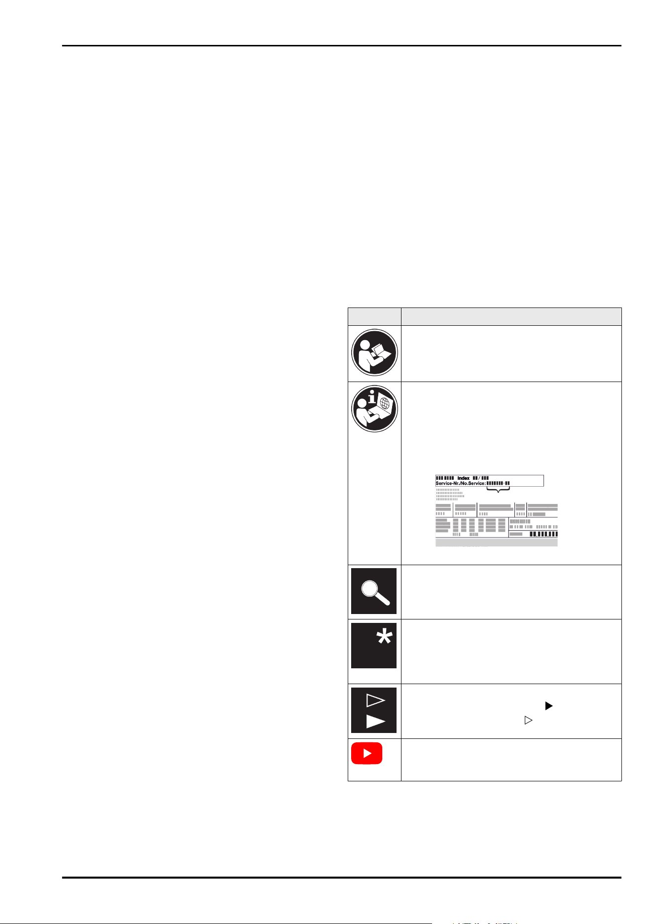
Read instructions
Please read the information in these instruc‐
tions carefully to understand all of the benefits
of your new appliance.
Additional information on the Internet*
The digital manual with additional information
can be found via the QR code on the front of
the manual or by entering the service number
at home.liebherr.com/fridge-manuals.*
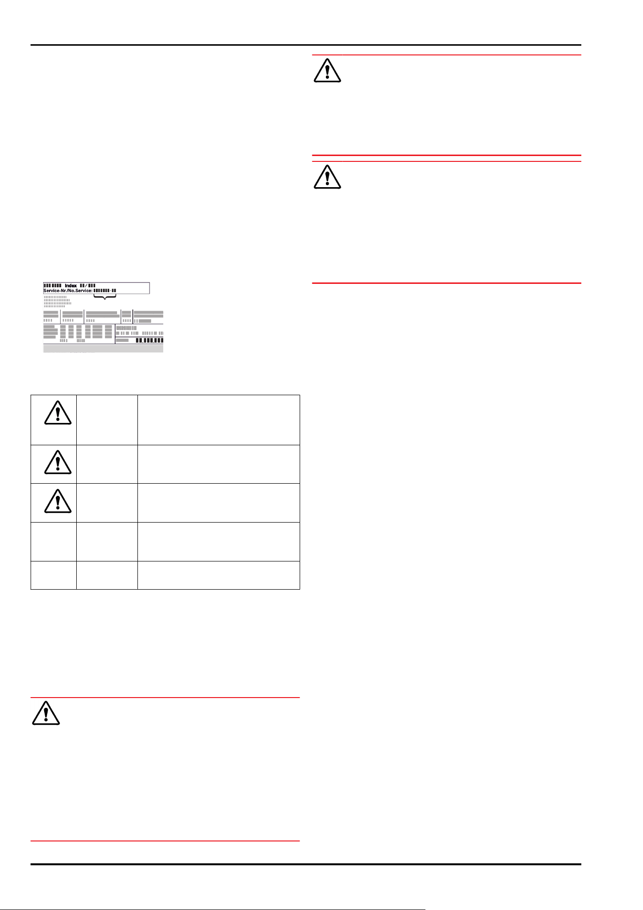
The service number can be found on the serial
tag:*
Fig.Example illustration*
Check appliance
Check all parts for transport damage. If you
have any complaints, please contact your
agent or customer service.
Differences
These instructions apply to a range of models,
so differences are possible. Sections that
apply to certain models only are marked with
an asterisk (*).
Instructions and results
Instructions are marked with a .
Results are marked with a .
Videos
Videos about the appliances are available on
the YouTube channels of Liebherr-Hausgeräte.
Open source licences:
The appliance contains software components that use
open source licences. Information on the open source
licences used can be found here: home.liebherr.com/
open-source-licences
2 * Depending on model and options
1 General safety instructions
-
Please keep this assembly manual in a safe place so you
can refer back to it at any time.
-
If you pass the appliance on, please hand this assembly
manual to the next user.
-
Read this assembly manual carefully before installation
and use to ensure safe and correct use of the appliance.
Follow the instructions, safety instructions and warning
messages included at all times. They are important for
ensuring you can operate and install the appliance safely
and without any problems.
-
First read the general safety instructions in the
“General safety instructions” section of the oper‐
ating instructions, which accompany these installation
instructions, and follow them. If you cannot find the
operating instructions, you can download the oper‐
ating instructions from the internet by entering the
service number at home.liebherr.com/fridge-manuals.
The service number can be found on the serial tag:
-
Observe the warning messages and other detailed infor‐
mation in the other sections when installing the appli‐
ance:
DANGER
identifies a situation involving
direct danger which, if not obvi‐
ated, may result in death or severe
bodily injury.
WARNING identifies a dangerous situation
which, if not obviated, may result
in death or severe bodily injury.
CAUTION identifies a dangerous situation
which, if not obviated, may result
in minor or medium bodily injury.
NOTICE identifies a dangerous situation
which, if not obviated, may result
in damage to property.
Note identifies useful instructions and
tips.
2 Installation requirements
The installation conditions are crucial to ensure that you
can operate your appliance safely, efficiently and without
problems.
-
Observe all safety instructions.
-
Consider the location and position in the room.
WARNING
Danger of fire due to incorrect positioning!
► Make sure the mains cable is not trapped under the appli‐
ance when you position the appliance.
► Position the appliance so that it does not touch the plug
or mains cable.
► Do not connect any appliances to sockets in the area of
the back of the appliance.
► Do not place and operate multi-sockets/power distribu‐
tors and other electronic devices (such as halogen trans‐
formers) at the back of the appliances.
WARNING
Fire hazard due to dampness!
If live parts or the mains lead become damp this may cause
short circuits.
► The appliance is designed for use in enclosed areas. Do
not operate the appliance outdoors or in areas where it is
exposed to splash water or damp conditions.
WARNING
Leaking coolant and oil!
Fire. The coolant contained in the appliance is eco-friendly,
but also flammable. The oil contained in the appliance
is flammable. Escaping coolant and oil can ignite if the
concentration is high enough and in contact with an
external heat source.
► Do not damage the pipelines of the coolant circuit and
the compressor.
2.1 Installation site
-
Only set up and use the appliance in enclosed spaces.
-
Only operate the appliance when it is installed.
-
If the appliance is installed in a very damp environment,
condensation may form on the appliance exterior.
Always make sure there is good ventilation and aeration
at the installation site.
-
The more refrigerant there is in the appliance, the larger
than room must be in which it is located. In rooms that
are too small, a leak can product a flammable gas/air
mixture. For every 8g of refrigerant, the installation room
must be at least 1m
3
in size. Information on the refrig‐
erant contained is given on the type plate inside the
appliance.
-
The floor on which the appliance stands must be hori‐
zontal and level.
2.2 Position in space
-
Do not install the appliance in direct sunlight or near
radiators or similar sources of heat.
-
You can install the appliance directly next to an oven.
-
If the appliance is installed directly next to an oven,
the energy consumption may increase slightly. This is
dependent on the service life and usage intensity of the
oven.
-
If you install the appliance in a island unit, appliances
with an integrated exhaust air system can damage the
appliance. Either ensure separate air ducting or install a
partition wall between the appliances.
-
Use in hazardous areas is not permitted.
2.3 Insert under worktop
-
If you are installing the appliance in a kitchen unit that is
standing on uneven ground: Levelling kitchen furniture.
General safety instructions
* Depending on model and options 3
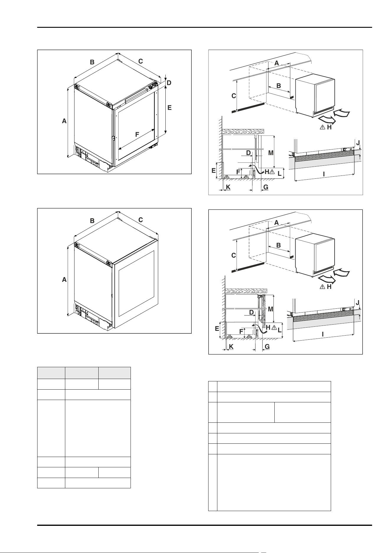
3 Appliance dimensions
B
C
A
D
E
F
Fig. 1 Example illustration: ..pr
(A)
Appliance height
including feet
(C) Appliance depth
(B) Appliance width
Fig. 2 Example illustration: ..gb
(A)
Appliance height
including feet
(C) Appliance depth
(B) Appliance width
UW..36..
A)
UW.. 37..
A)
A 819mm 859mm
B 597mm
C
UW..pr:
A)
564mm
UW..gb ..3.:
A)
576mm*
UW..gb..8.:
A)
580mm*
D 98mm
E 524mm 568,5mm
F 458mm
A)
Appliance type designation
4 Recess dimensions
A
B
C
H
I
J
H
K
E
F
G
D
L
M
Fig. 3 Example illustration: UW..gb
A
B
C
H
I
J
H
K
E
F
G
D
L
M
Fig. 4 Example illustration: UW..pr
(A)
Niche width (C) Niche height
(B) Niche depth (H) Ventilation cross-section
A 600mm
B min. 565mm
C
UW..36..:
A)
820mm to 880mm
UW.. 37..:
A)
860mm to 920mm
D 11mm to 66mm
E 100mm to 160mm
F 60mm to 120mm
G
UW..pr:
A)
45mm to 100mm
UW..gb ..3.:
A)
57mm to 112mm
UW..gb..8.:
A)
61mm to 116mm
Appliance dimensions
4 * Depending on model and options
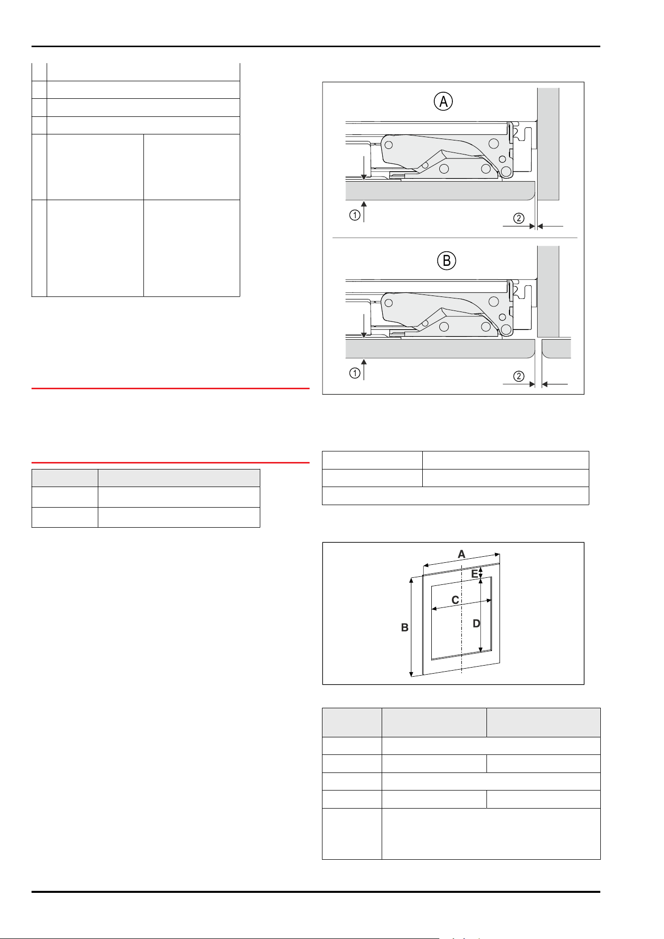
H 150cm²
I 600mm
J 40mm
K 35mm
L
UW..pr36..:
A)
104mm to 164mm
UW..gb ..36.:
A)
100mm to 160mm
UW..pr 37..:
A)
104mm to 164mm
UW..gb 37.:
A)
81mm to 141mm
M
UW..pr366.:
A)
707mm
UW..pr 367.:
A)
704mm
UW..gb ..36.:
A)
717mm
UW..pr 37..:
A)
747mm
UW..gb 37.:
A)
776mm
A)
Appliance type designation
5 Unit front
5.1 Unit front weight
NOTICE
A heavy unit door may pose a risk of damage!
If the unit door is too heavy, damage to the hinges cannot
be ruled out, which may compromise functionality.
► Before fitting the unit door, ensure that the unit door
does not exceed the permissible weight.
Niche height Maximum weight of the unit door
.. 36..
A)
10 kg
.. 37..
A)
10 kg
A)
Appliance type designation
5.2 Unit door
1
1
2
2
A
B
Fig. 5 Example illustration
(A)
Niche with wall (1) Front thickness
(B) Niche with neigh‐
bouring furniture
(2) Gap dimension
Front thickness At least 16mm to max. 19mm
Gap dimension At least 3mm
The unit door must be flat and mounted without tension.
5.3 Unit front dimensions
Fig.6
Niche
height
.. 36.. .. 37..
A At least 595mm
B At least 707mm At least 747mm
C 458mm
D 524mm 568.5mm
E Dimensions depends on the installation situa‐
tion in the niche. You can calculate it with the
cut-out dimensions of the glass door front.
(see3Appliance dimensions)
Unit front
* Depending on model and options 5
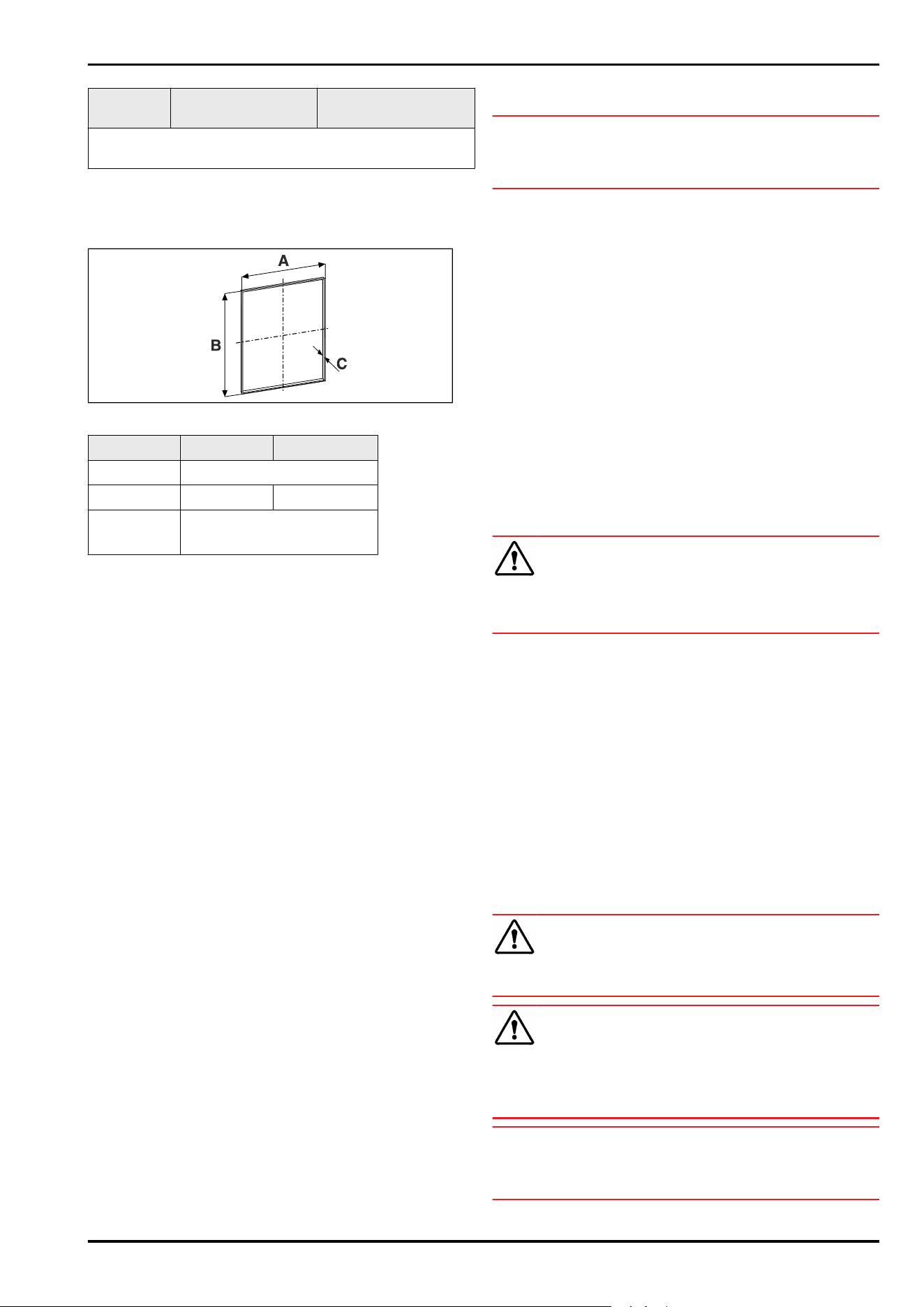
Niche
height
.. 36.. .. 37..
Values C, D and E do not apply to appliances without a
glass door.
A)
Appliance type designation
5.4 Profile frame dimensions
Fig.7
Niche height
.. 36.. .. 37..
A 458mm
B 524mm 568.5mm
C With panel thickness 19mm:
21mm
A)
Appliance type designation
A = Internal dimensions for cut-out in unit front profile
frame mounting
B = Internal dimensions for cut-out in unit front profile
frame mounting
C = Profile frame thickness
6 Transporting the appliance
6.1 Transporting the appliance for initial
use
Ensure that the following requirements are met:
❑
The appliance is packaged.
❑
The appliance is upright.
► Transport the appliance with the help of two people.
► Unpacking the appliance. (see7 Unpacking the appliance)
6.2 Transporting the appliance after
initial use
Observe the following instructions if you wish to transport
or move the appliance again after initial use.
Ensure that the following requirements are met:
❑
The appliance is emptied.
❑
The appliance is upright.
❑
Appliance with door(s): Door is secured against acci‐
dental opening.
❑
Appliance with telescopic unit: The telescopic unit is
secured against accidental opening.
❑
Appliance is removed.
► Transport the appliance with the help of two people.
7 Unpacking the appliance
NOTICE
Risk of damage to the floor!
► Protect your floors by covering them before removing
packaging from the appliance.
Before you connect the appliance, report any damage imme‐
diately to the delivery company.
► Check the appliance and the packaging for damage
during transport. Contact the supplier immediately if you
suspect any level of damage.
► Remove all materials from the back or the side walls
of the appliance that may prevent proper installation or
ventilation.
► Remove all protective films from the appliance. Do not
use sharp or pointed objects for this.
8 After installation
► Peel off the protective films. *
► Clean appliance.
► Keep the invoice so you have the appliance and dealer
information available if needed.
9 Disposing of packaging
WARNING
Danger of suffocation due to packing material and plastic
film!
► Do not allow children to play with packing material.
The packaging is made of recyclable materials:
-
corrugated board/cardboard
-
expanded polystyrene parts
-
polythene bags and sheets
-
polypropylene straps
-
nailed wooden frame with polyethylene panel*
► Take the packaging material to an official collecting
point.
10 Replacing the door hinge with
bearing bracket hinge
10.1 Safety instructions
WARNING
Risk of injury if the door is not reversed correctly!
► Replace the door hinge with specialist personnel.
WARNING
Risk of injury and material damage due to door weight!
► Only change the door hinge if you can carry a weight of
15 kg.
► Change the door hinge with two people.
NOTICE
Live parts!
Damage to electrical components.
► Remove the mains plug before you reverse the door.
Transporting the appliance
6 * Depending on model and options
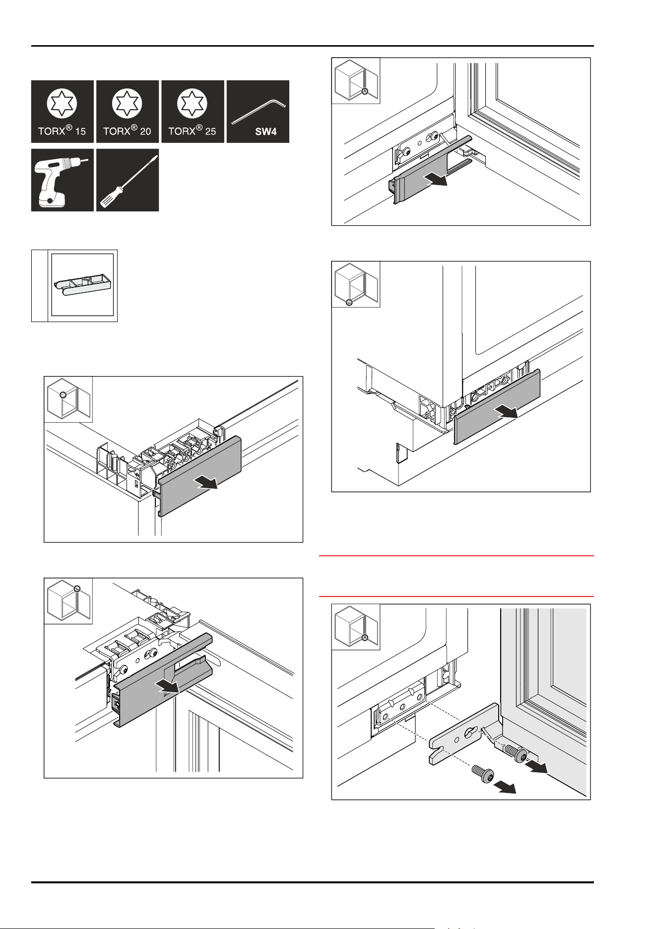
10.2 Tool
10.3 Scope of supply
1x
10.4 Removing covers
► Open the door.
Fig.8
► Remove cover.
Fig.9
► Remove cover.
Fig. 10
► Remove cover.
Fig.11
► Remove cover.
10.5 Removing the door
NOTICE
Risk of injury if the door tips out!
► Hold the door.
Fig.12
► Loosen screws at bottom.
Replacing the door hinge with bearing bracket hinge
* Depending on model and options 7
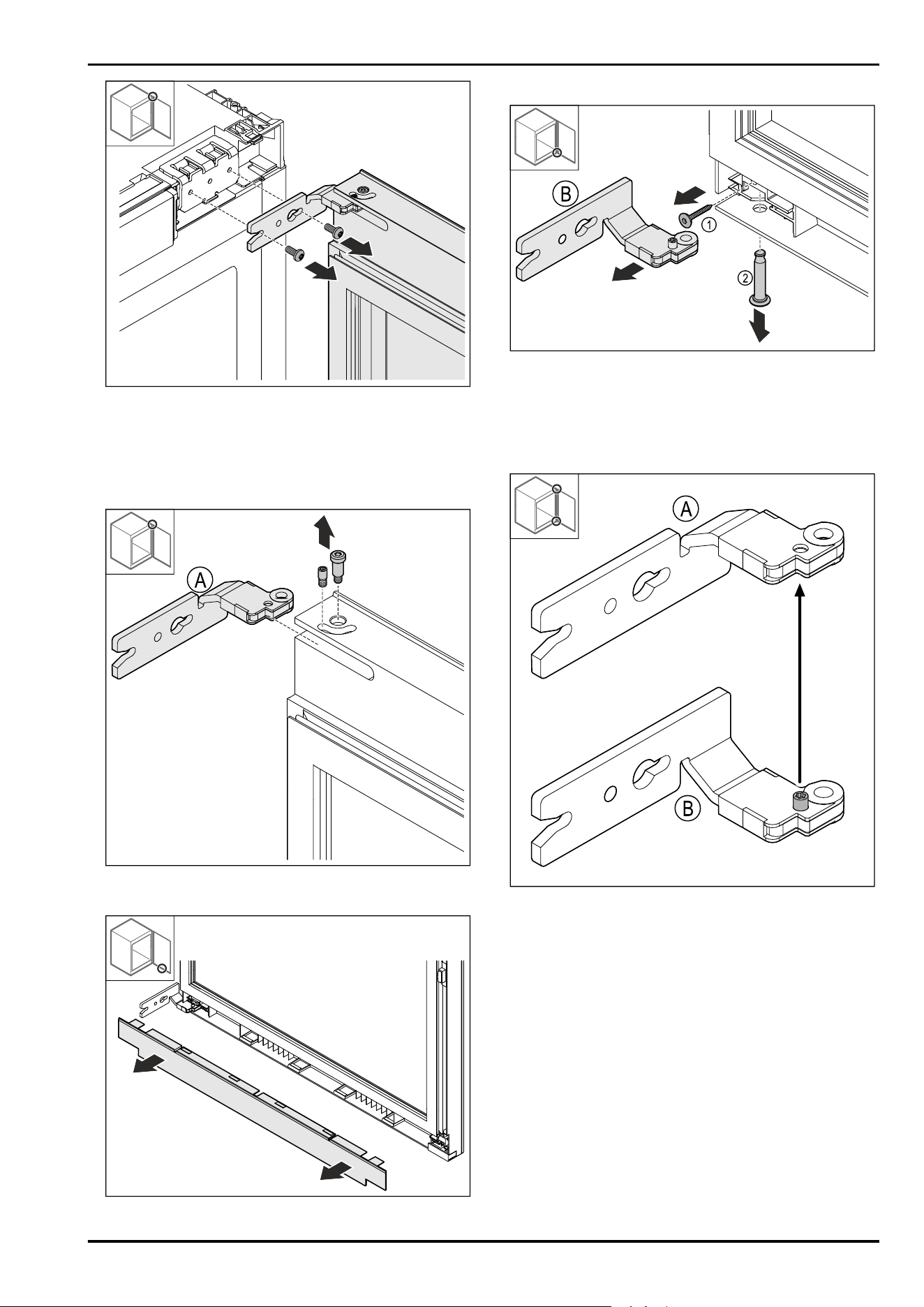
Fig.13
► Loosen screws at top.
► Remove the door.
► Place the door on a soft surface.
10.6 Removing the hinge
Fig. 14
► Unscrew the bolt.
Fig. 15
►
Remove cover.
Fig. 16
► Remove the screw Fig. 16(1).
► Remove the bolt Fig. 16(2).
► Remove the hinge Fig. 16(B).
10.7 Converting the hinge
Fig.17
► Relocate the screw.
Replacing the door hinge with bearing bracket hinge
8 * Depending on model and options
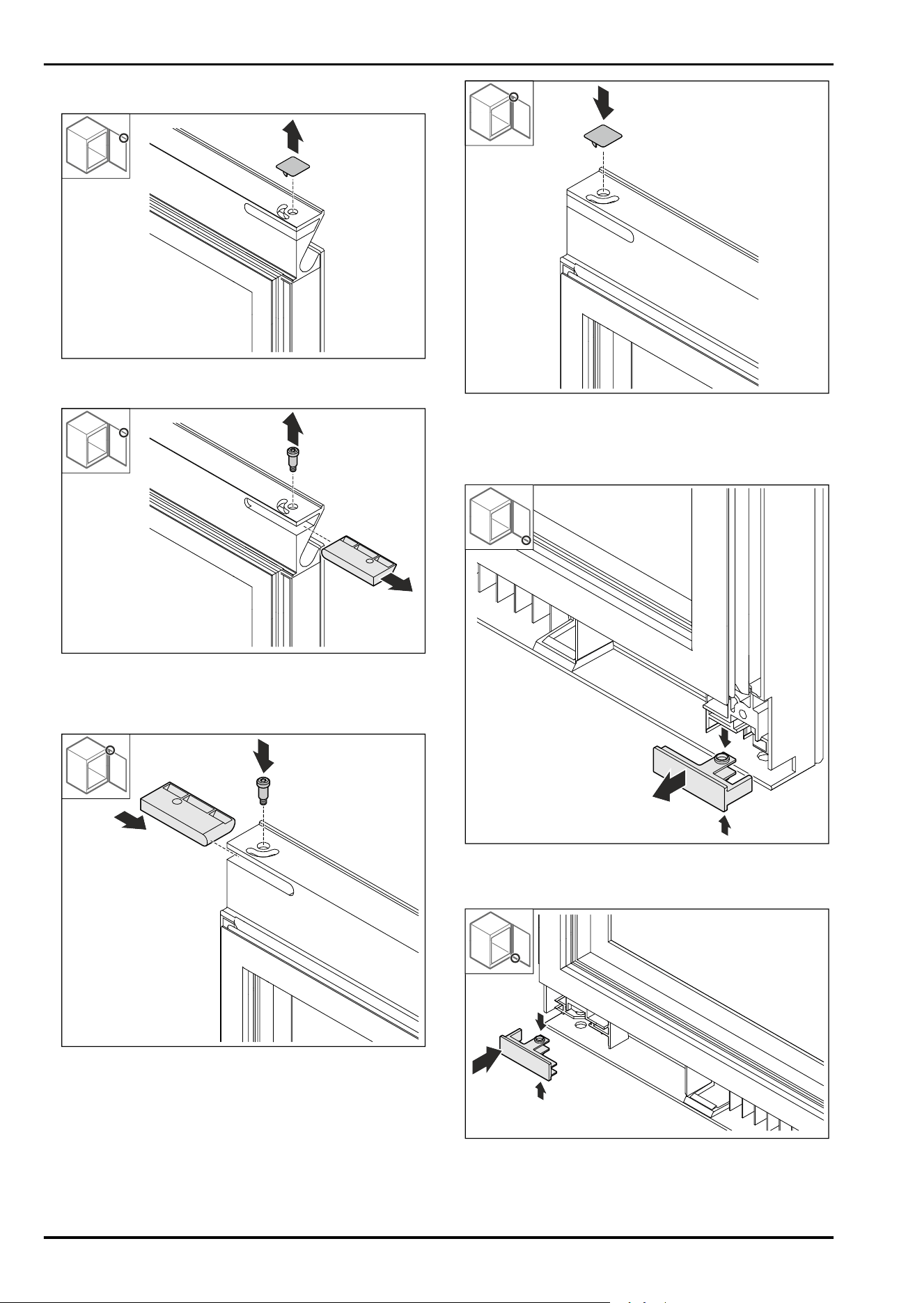
10.8 Relocating the upper cover
Fig. 18
► Remove the cover.
Fig. 19
► Remove the bolts.
► Remove the cover.
► Recommendation: Keep the cover for later use.
Fig.20
► Insert the cover from the accessory pack.
► Tighten the bolt.
Fig.21
► Insert the cover.
10.9 Relocating the lower cover
Fig.22
► Gently press the top and bottom of the cover together
and pull it out forwards.
Fig.23
► Turn the cover 180° and insert it on the opposite side.
Replacing the door hinge with bearing bracket hinge
* Depending on model and options 9
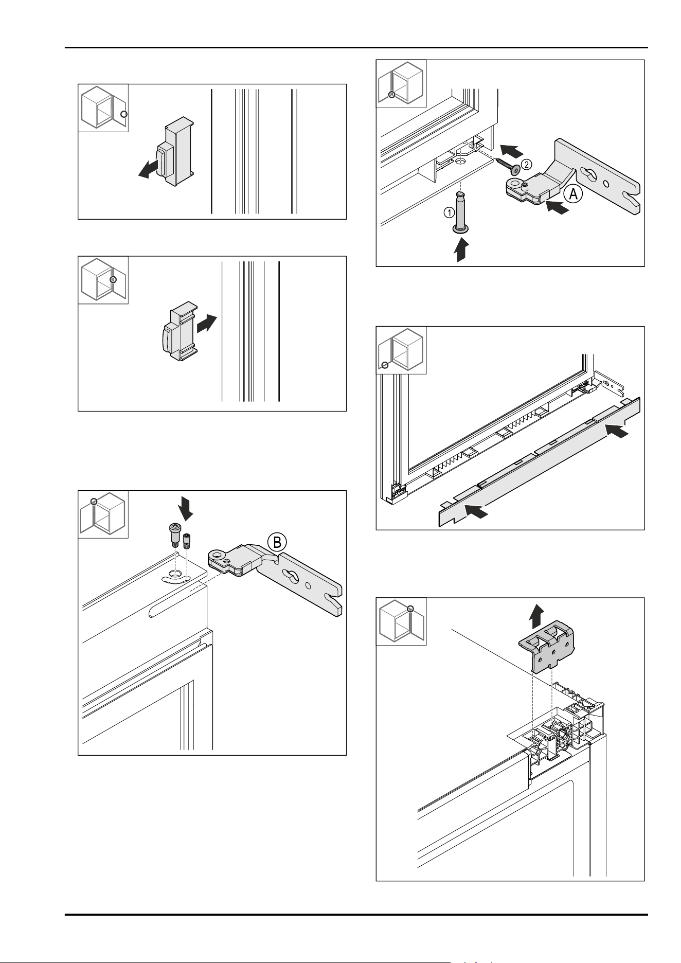
10.10 Relocating the door stopper*
Fig. 24
► Pull out the door stopper.
Fig.25
► Insert the door stopper rotated by 180° on the opposite
side.
10.11 Fitting the hinges
Fig. 26
► Fit the upper hinge.
Fig.27
► Insert the lower hinge Fig.27(A).
► Insert and hold the bolt in place Fig.27(1).
► Screw the screw Fig.27(2) tight.
Fig.28
► Put on the cover.
10.12 Relocating the upper bracket
Fig.29
Replacing the door hinge with bearing bracket hinge
10 * Depending on model and options
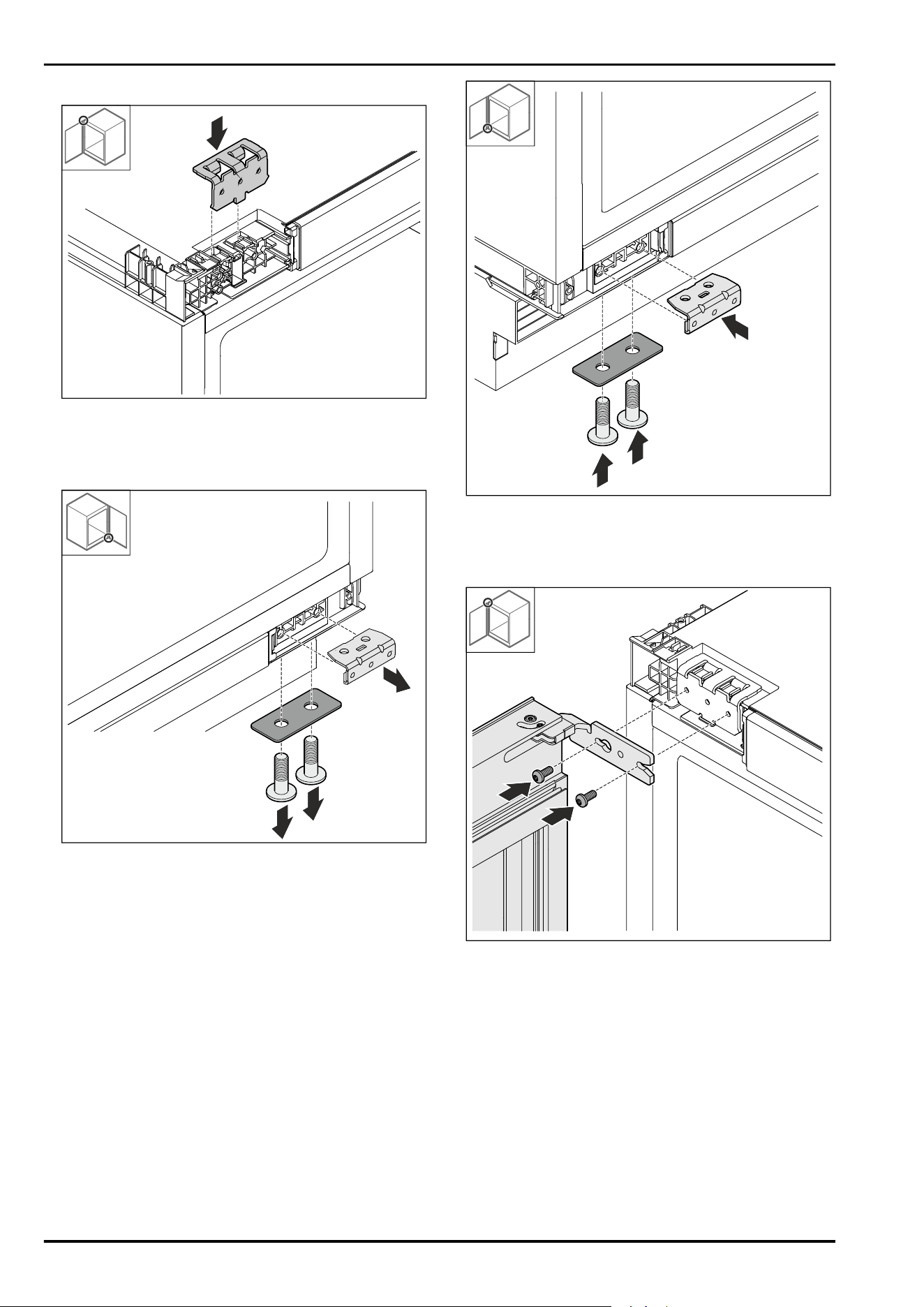
► Remove the bracket.
Fig.30
► Insert the bracket.
10.13 Relocating the bottom bracket
Fig.31
► Detach the bracket.
Fig.32
► Fit the bracket.
10.14 Fitting the door
Fig.33
► Screw on door at the top.
Replacing the door hinge with bearing bracket hinge
* Depending on model and options 11
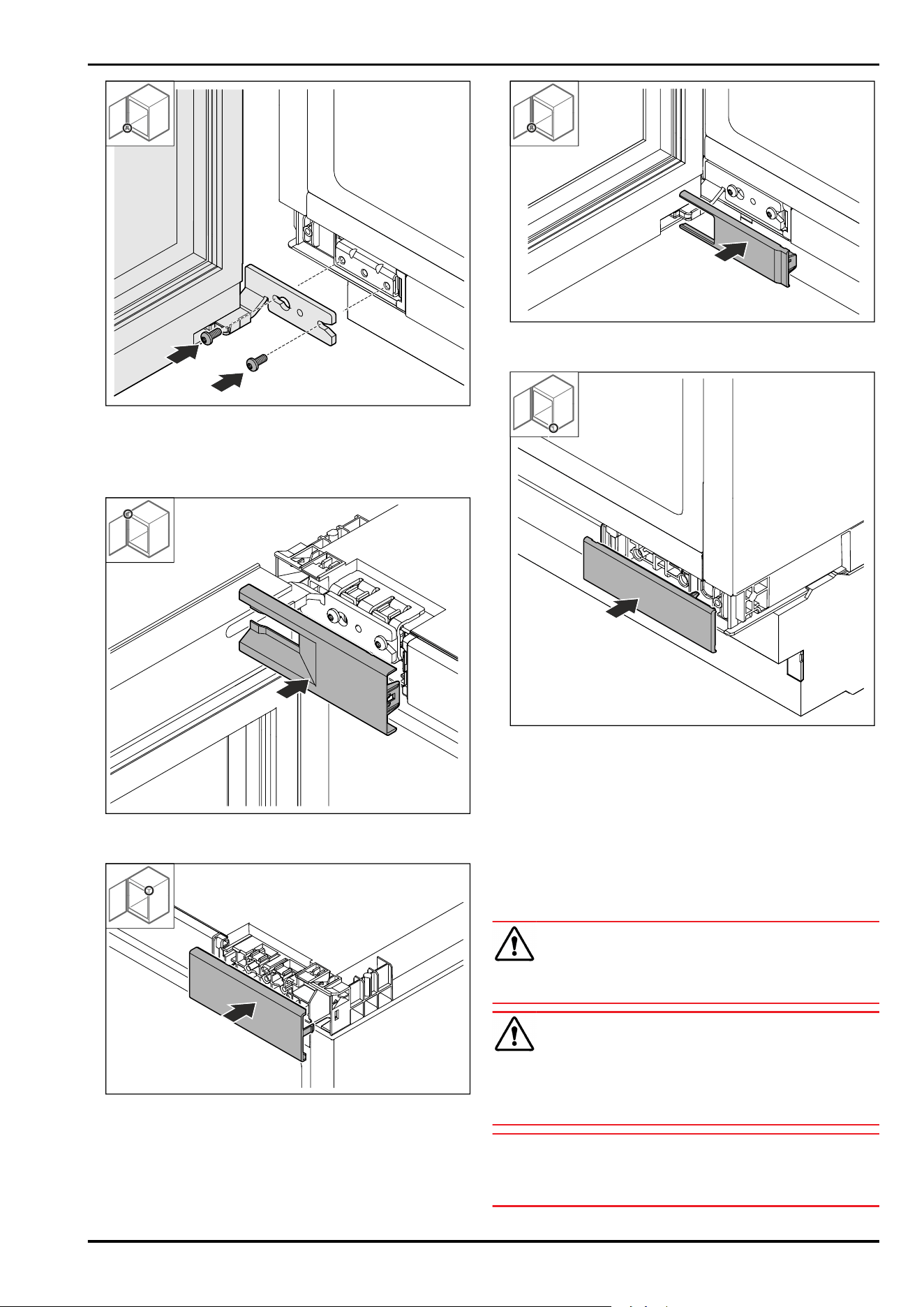
Fig.34
► Screw on door at the bottom.
10.15 Putting on the covers
Fig.35
► Put on the cover.
Fig.36
► Put on the cover.
Fig.37
► Put on the cover.
Fig.38
► Put on the cover.
11 Replacing the door hinge
with multi-joint hinge (not decor-
compatible)
11.1 Safety instructions
WARNING
Risk of injury if the door is not reversed correctly!
► Replace the door hinge with specialist personnel.
WARNING
Risk of injury and material damage due to door weight!
► Only change the door hinge if you can carry a weight of
15 kg.
► Change the door hinge with two people.
NOTICE
Live parts!
Damage to electrical components.
► Remove the mains plug before you reverse the door.
Replacing the door hinge with multi-joint hinge (not decor-
compatible)
12 * Depending on model and options
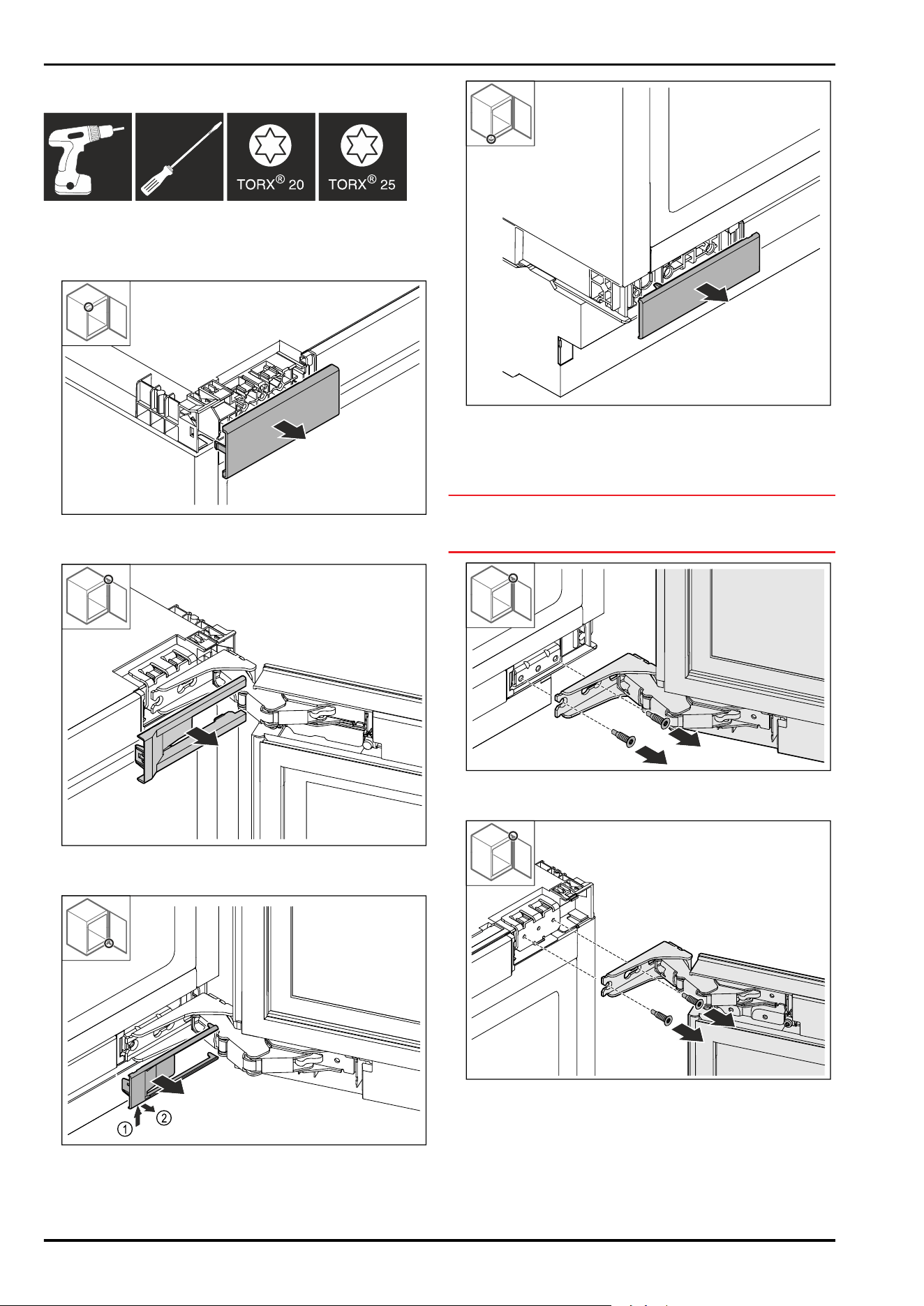
11.2 Tool
11.3 Removing covers
► Open the door.
Fig. 39
► Remove cover.
Fig.40
► Remove cover.
Fig. 41
► Remove cover.
Fig. 42
► Remove cover.
11.4 Removing the door
NOTICE
Risk of injury if the door tips out!
► Hold the door.
Fig.43
► Loosen screws at bottom.
Fig.44
► Loosen screws at top.
► Remove the door.
► Place the door on a soft surface.
Replacing the door hinge with multi-joint hinge (not decor-
compatible)
* Depending on model and options 13
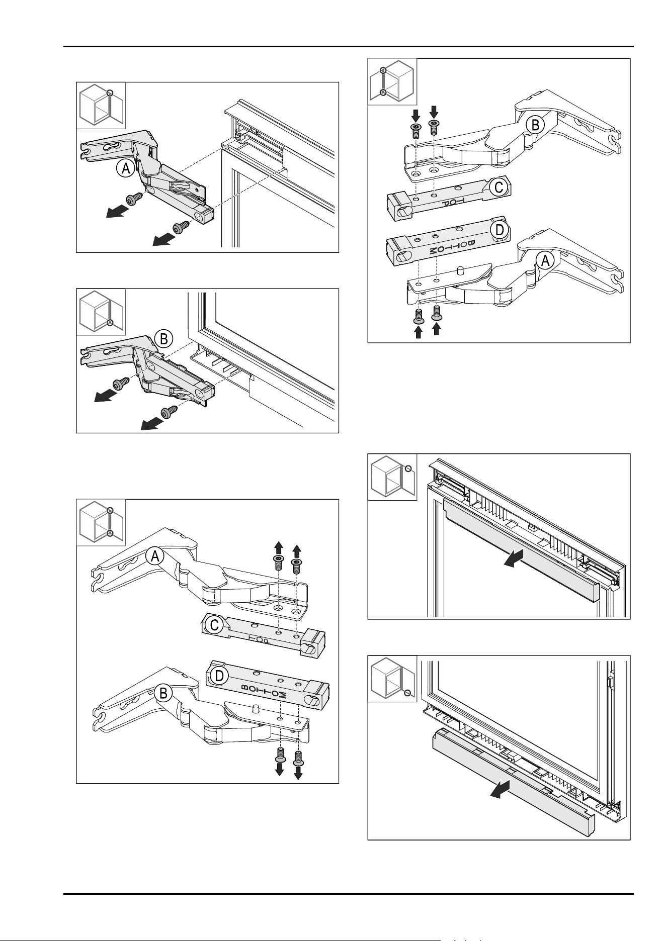
11.5 Removing the hinge
Fig.45
► Unscrew the screws.
Fig.46
► Unscrew the screws.
11.6 Converting the hinge
Fig. 47
► Removing the brackets.
Fig.48
► Fitting the brackets.
▷ Upper bracket (TOP) remains in the upper installation
position.
▷ Lower bracket (BOTTOM) remains in the lower installation
position.
11.7 Swapping covers
Fig. 49
► Loosen the top cover.
Fig.50
► Loosen the bottom cover
Replacing the door hinge with multi-joint hinge (not decor-
compatible)
14 * Depending on model and options
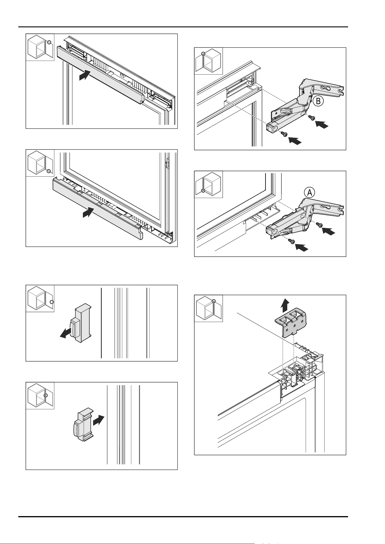
Fig.51
► Insert the cover at the top, rotated 180° from below.
Fig.52
► Insert the cover at the bottom, rotated 180° from above.
11.8 Relocating the door stopper
Fig.53
► Pull out the door stopper.
Fig.54
► Insert the door stopper rotated by 180° on the opposite
side.
11.9 Fitting the hinges
Fig.55
► Fit the upper hinge.
Fig.56
► Fit the lower hinge.
11.10 Relocating the upper bracket
Fig.57
► Remove the bracket.
Replacing the door hinge with multi-joint hinge (not decor-
compatible)
* Depending on model and options 15
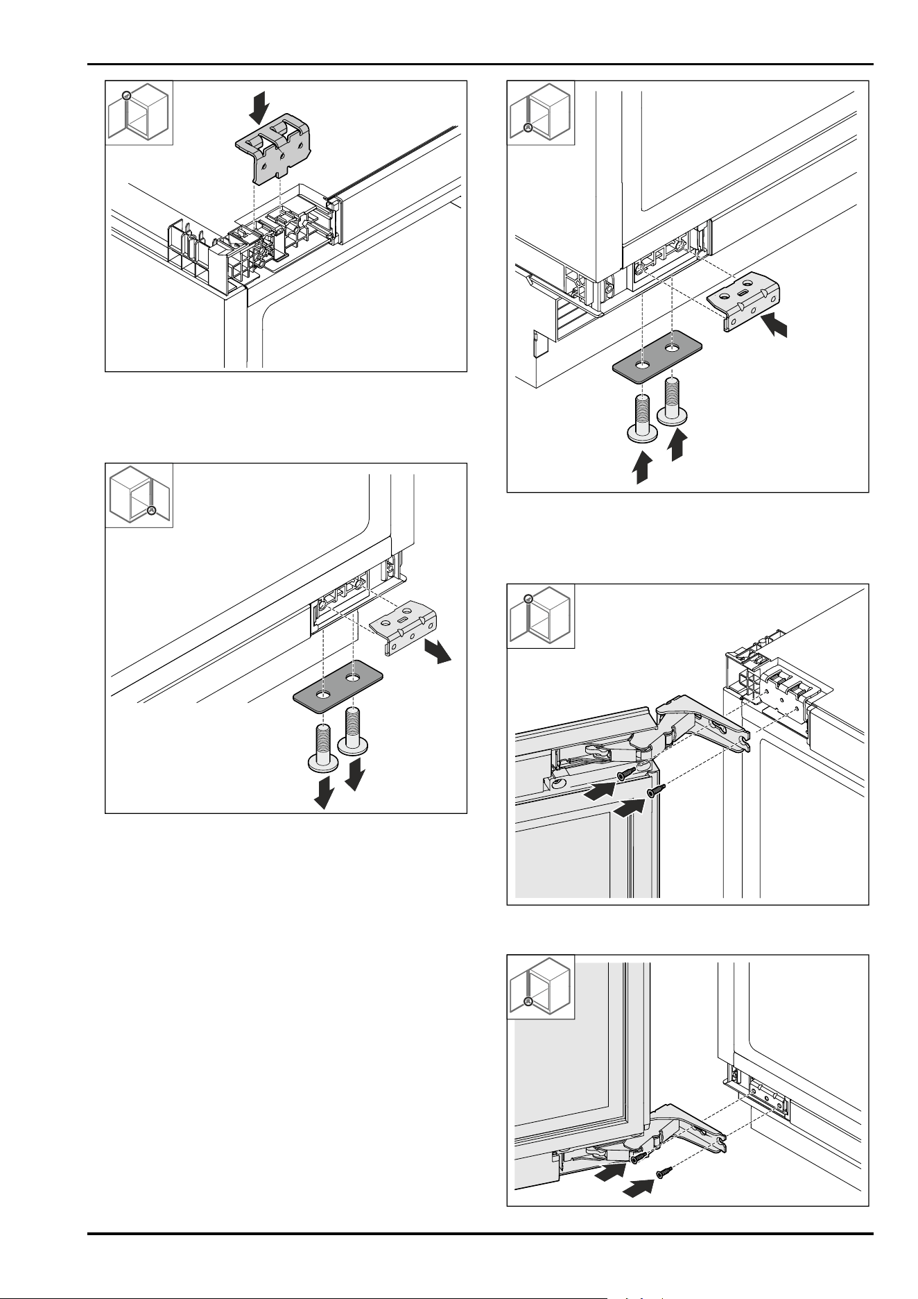
Fig.58
► Insert the bracket.
11.11 Relocating the bottom bracket
Fig. 59
► Detach the bracket.
Fig.60
► Fit the bracket.
11.12 Fitting the door
Fig.61
► Screw on door at the top.
Replacing the door hinge with multi-joint hinge (not decor-
compatible)
16 * Depending on model and options
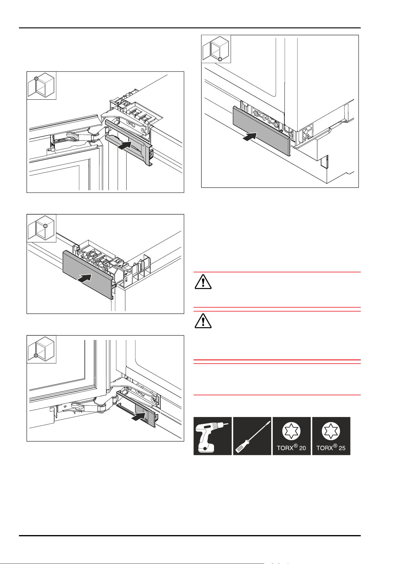
Fig. 62
► Screw on door at the bottom.
11.13 Putting on the covers
Fig.63
► Put on the cover.
Fig.64
► Put on the cover.
Fig.65
► Put on the cover.
Fig.66
► Put on the cover.
12 Replacing door hinge with
multi-joint hinge (decor-compat‐
ible)
12.1 Safety instructions
WARNING
Risk of injury if the door is not reversed correctly!
► Replace the door hinge with specialist personnel.
WARNING
Risk of injury and material damage due to door weight!
► Only change the door hinge if you can carry a weight of
15 kg.
► Change the door hinge with two people.
NOTICE
Live parts!
Damage to electrical components.
► Remove the mains plug before you reverse the door.
12.2 Tool
12.3 Removing covers
► Open the door.
Replacing door hinge with multi-joint hinge (decor-compatible)
* Depending on model and options 17
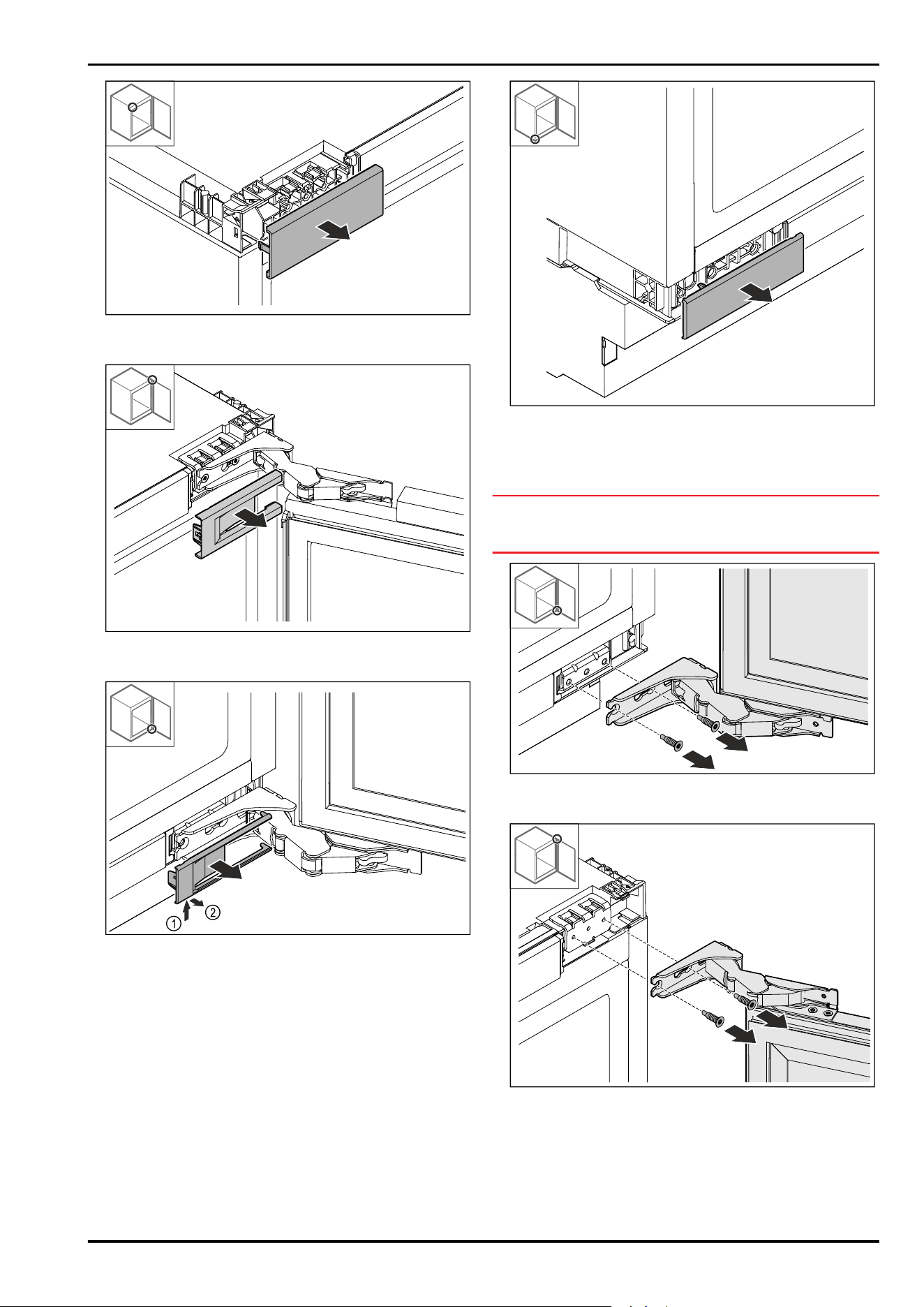
Fig. 67
► Remove cover.
Fig.68
► Remove cover.
Fig. 69
► Remove cover.
Fig.70
► Remove cover.
12.4 Removing the door
NOTICE
Risk of injury if the door tips out!
► Hold the door.
Fig.71
► Loosen screws at bottom.
Fig.72
► Loosen screws at top.
► Remove the door.
► Place the door on a soft surface.
Replacing door hinge with multi-joint hinge (decor-compatible)
18 * Depending on model and options
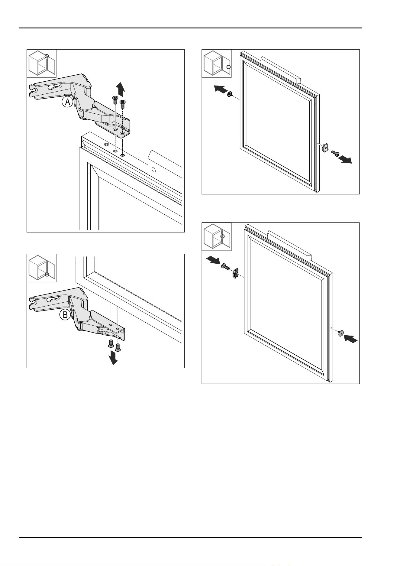
12.5 Removing the hinge
Fig.73
► Unscrew the screws.
Fig. 74
► Unscrew the screws.
12.6 Relocating the door stopper
Fig.75
► Remove cover Fig.75(1).
► Detach the Fig.75(2) door stopper.
Fig. 76
► Turn the door stopper Fig. 76(1) 180° and fit it on the
opposite side.
► Insert the cover Fig. 76(2) on the opposite side.
Replacing door hinge with multi-joint hinge (decor-compatible)
* Depending on model and options 19
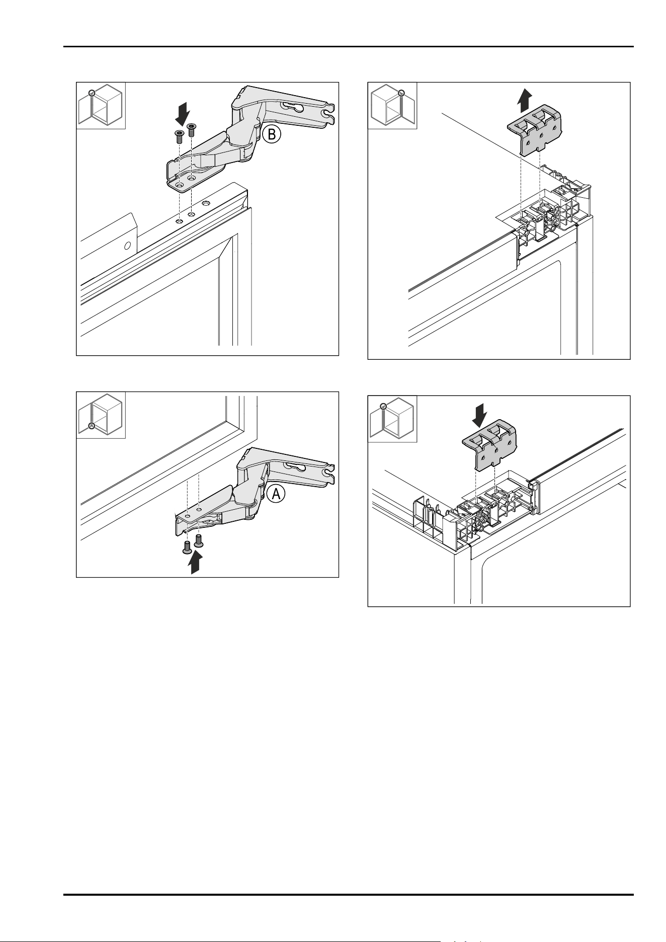
12.7 Fitting the hinges
Fig.77
► Fit the upper hinge.
Fig.78
► Fit the lower hinge.
12.8 Relocating the upper bracket
Fig.79
► Remove the bracket.
Fig.80
► Insert the bracket.
Replacing door hinge with multi-joint hinge (decor-compatible)
20 * Depending on model and options
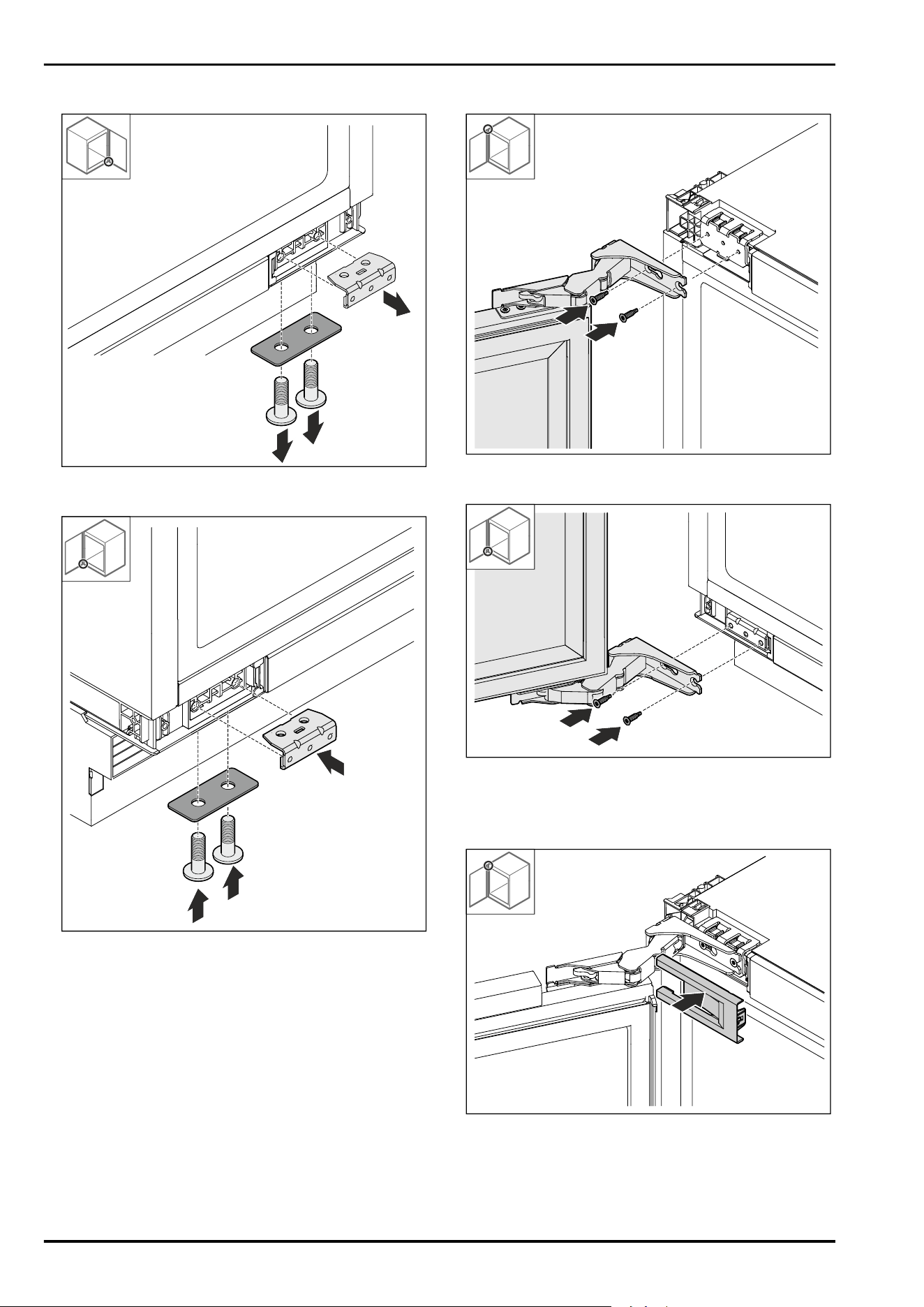
12.9 Relocating the bottom bracket
Fig.81
► Detach the bracket.
Fig.82
► Fit the bracket.
12.10 Fitting the door
Fig.83
► Screw on door at the top.
Fig.84
► Screw on door at the bottom.
12.11 Putting on the covers
Fig.85
► Put on the cover.
Replacing door hinge with multi-joint hinge (decor-compatible)
* Depending on model and options 21
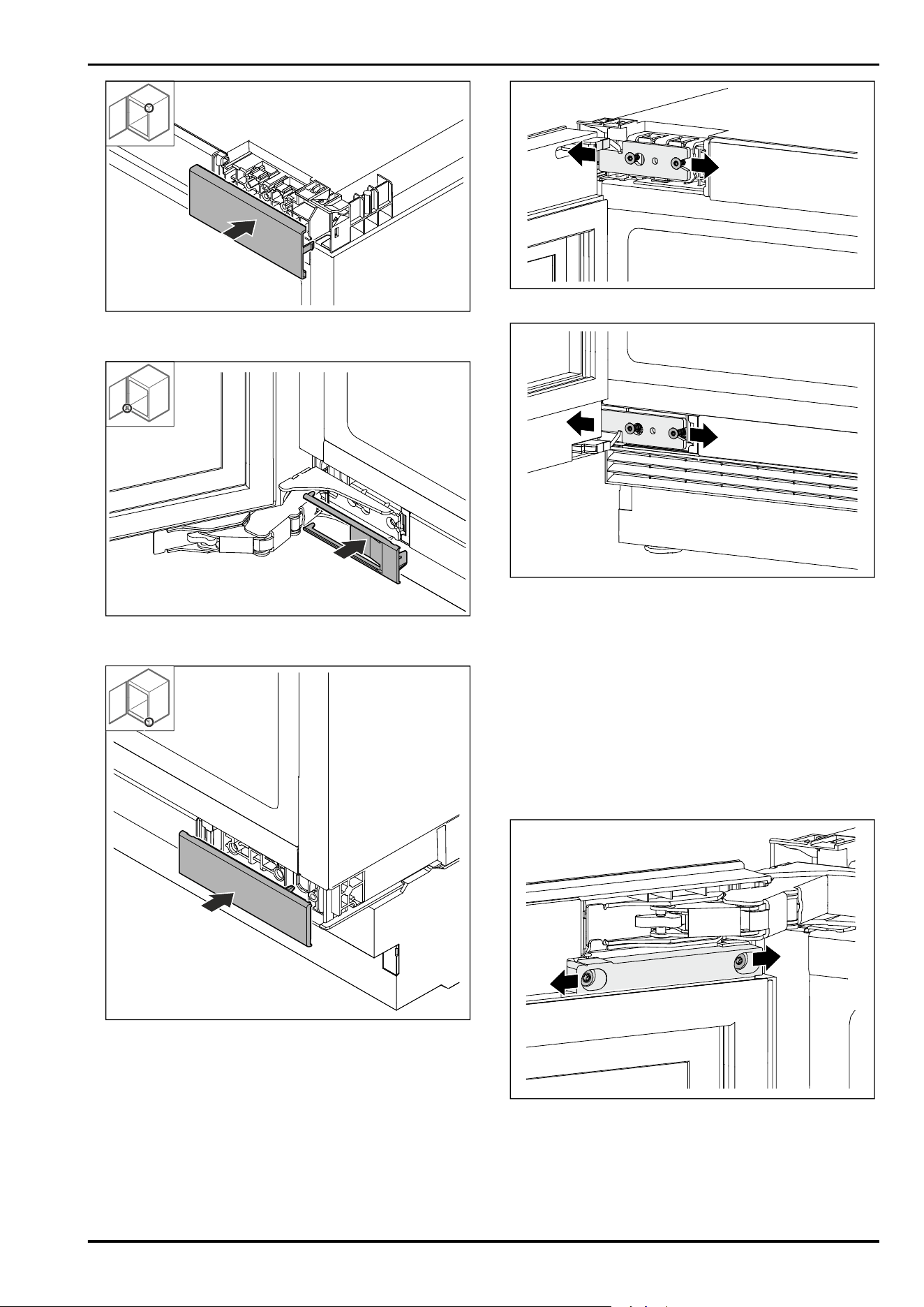
Fig.86
► Put on the cover.
Fig. 87
► Put on the cover.
Fig.88
► Put on the cover.
13 Aligning the door hinge with
bearing bracket hinge
If the door is not straight, it can be aligned at the hinge
angle.
Fig. 89 Example illustration
Fig. 90 Example illustration
► Loosen screws slightly.
► Move the door to the right or left with the hinge bracket.
► Tighten the screws as far as they will go.
▷ The door is aligned.
14 Aligning the door hinge
with multi-joint hinge (not decor-
compatible)
If the door is not straight, it can be aligned at the hinge
angle.
Fig. 91 Example illustration
Aligning the door hinge with bearing bracket hinge
22 * Depending on model and options
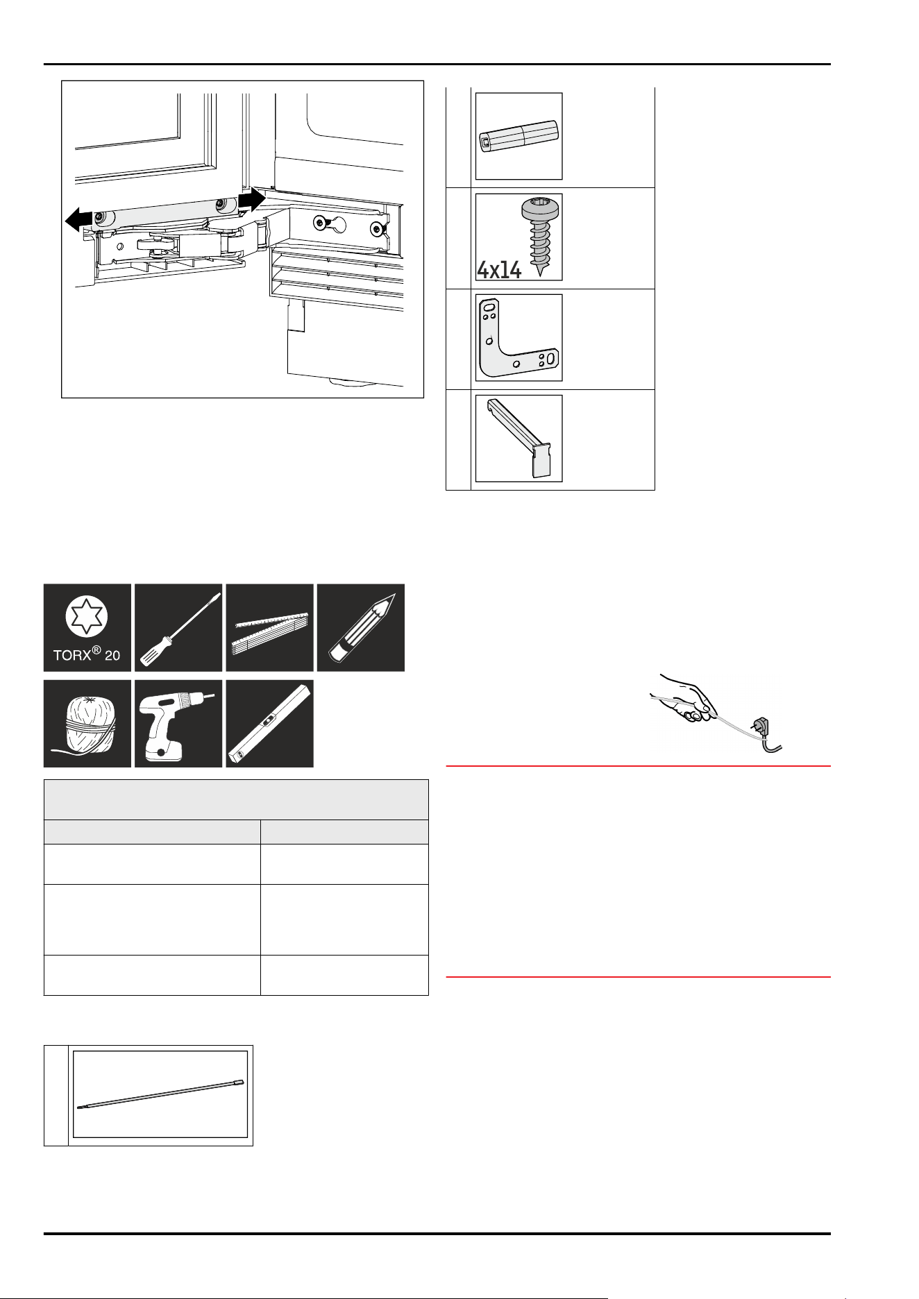
Fig. 92 Example illustration
► Loosen screws slightly.
► Move the door to the right or left with the hinge bracket.
► Tighten the screws as far as they will go.
▷ The door is aligned.
15 Recessed installation
15.1 Tool
Before installing the appliance in the niche, note the fixing
method:
Lateral fixing Ceiling mounting
Substructure under a hard
worktop such as granite
No granite slab
The appliance is lower than the
worktop when the adjustable
feet are fully extended.
Appliance sits slightly
braced under worktop
when adjustable feet are
fully extended.
Appliance side panel available
for screwing.
15.2 Scope of supply
1x
1x
2x
4x14
2x
2x
15.3 Preparing the appliance
Before installing the appliance in a niche, make sure that
the following requirements are met:
❑
The door hinge has been hung. You can only change the
door hinge from the outside of the niche because you
need enough space to do so.
► Plug the mains cable’s IEC socket completely into the
appliance plug on the back of the appliance.
► Ensure that the IEC socket is tight.
► Use a cord to lay the mains
plug to a freely accessible
socket.
Fig. 93
NOTICE
Risk of damage if the appliance is moved!
If you move the appliance, you may damage the floor or the
appliance's adjustable feet may break off.
Before moving:
► Screw in the levelling feet completely.
► Place a cardboard strip (e.g. packaging) with approx.
100mm x 600mm under each of the adjustable feet.
When moving:
► Move the appliance carefully.
► For uneven floors: Carefully lift the appliance.
After moving:
► Remove the cardboard strips.
Recessed installation
* Depending on model and options 23
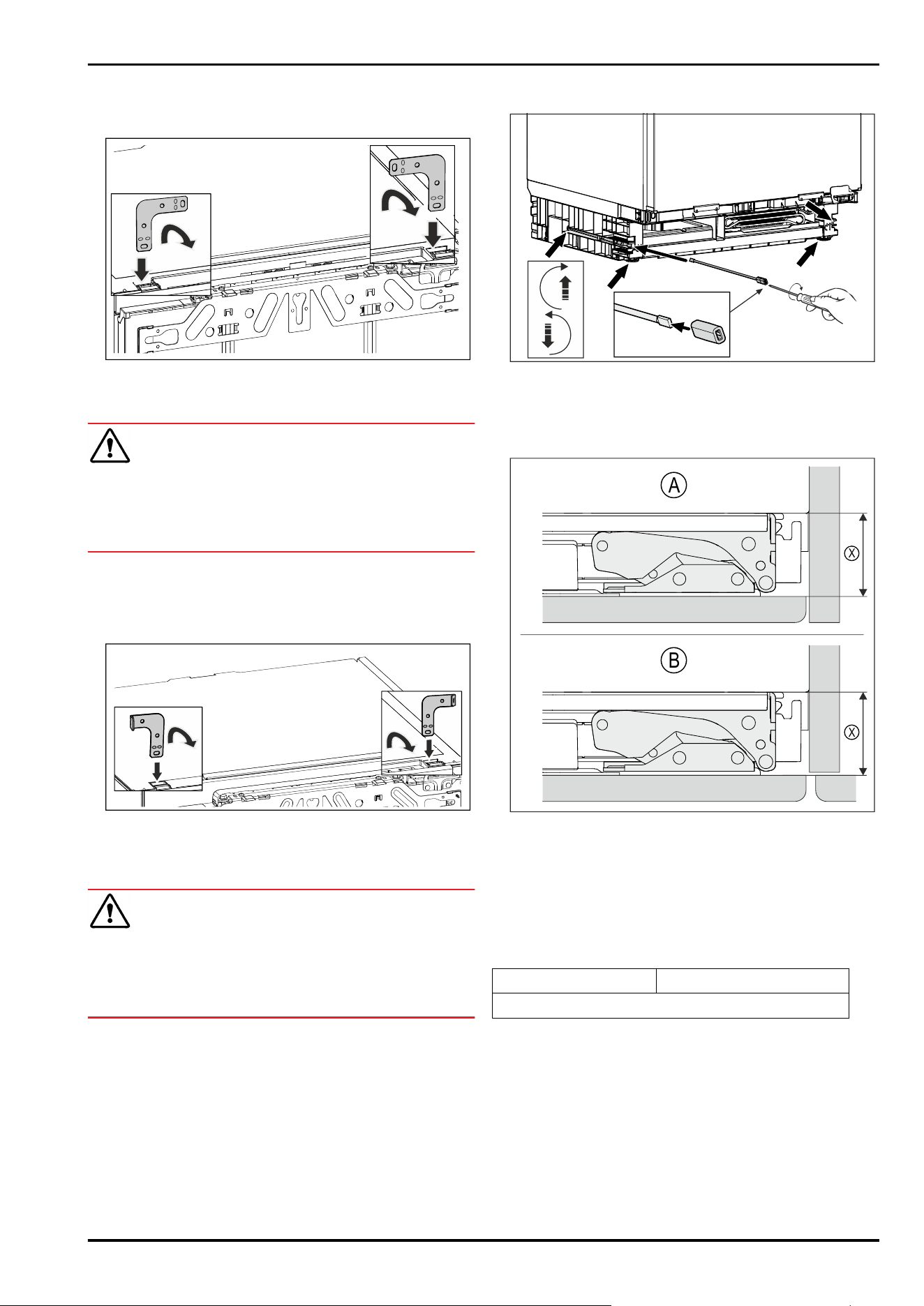
15.4 Screwing the appliance to the
ceiling
Fig. 94 Example illustration
► Insert the bracket into the opening in the unit ceiling and
bend it forwards.
WARNING
Risk of fire due to short circuit!
► When you push the appliance into the niche: do not kink,
jam or damage the mains cable.
► The appliance must not be operated with a defective
mains cable.
► Slide the appliance into the recess and align, see point
(see 15.6Aligning the appliance) .
15.5 Fixing the appliance on the side
Fig. 95 Example illustration
► Bend one end of each bracket before installation. Insert
the straight side into the opening in the appliance cover
and bend it forwards.
WARNING
Risk of fire due to short circuit!
► When you push the appliance into the niche: do not kink,
jam or damage the mains cable.
► The appliance must not be operated with a defective
mains cable.
► Slide the appliance into the recess and align, see point
(see 15.6Aligning the appliance) .
15.6 Aligning the appliance
Fig. 96 Example illustration
► Unscrew the levelling feet to below the worktop.
► Align the appliance in an upright position using a spirit
level.
► Keep the rod with adapter piece to remove the appliance.
X
X
A
B
Fig. 97 Example illustration
(A)
Niche with wall (X) is the distance between
the body of the appli‐
ance and the rear of the
mounted furniture front
(B) Niche with neigh‐
bouring furniture
► Check that the distance (X) corresponds to installation
situation (A) or (B).
(X)
42mm
If there is no unit side panel, orientate on the worktop.
► Unscrew the levelling feet alternately to the maximum.
The maximum adjustment travel is 60mm.
▷ Appliance is aligned upright.
▷ The appliance is slightly braced in the recess between
the floor and worktop.
Recessed installation
24 * Depending on model and options
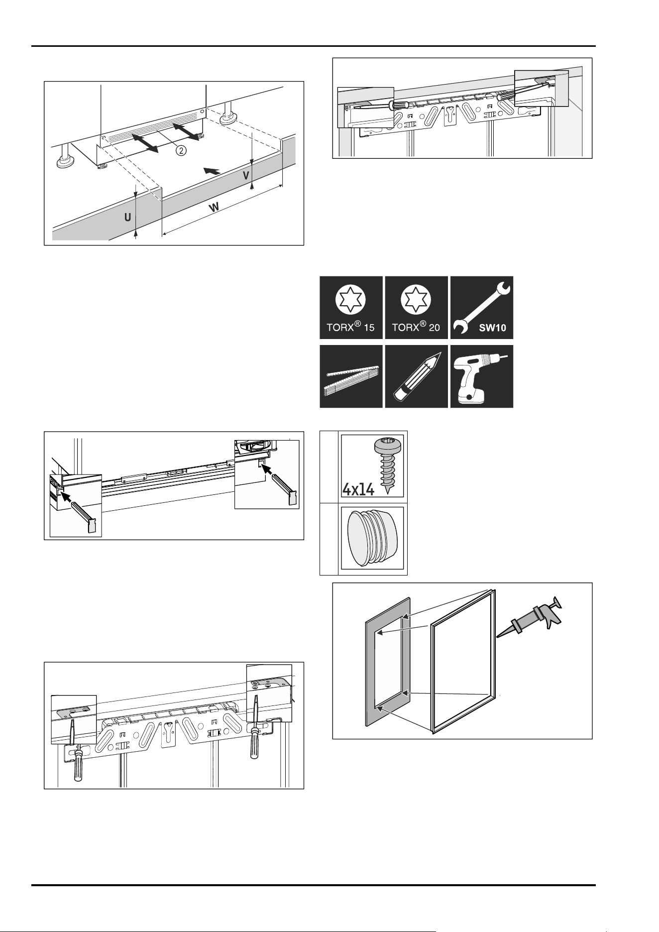
15.7 Fitting the base
Fig. 98 Example illustration
► Put on the appliance base cover Fig.98(2) but do not fix
it in place yet.
► Position the unit door and unit base panel for testing
► If the base panel is visible Fig.98(2), pull it forwards so
that the front edge of the ventilation grille and the unit
base panel are level.
-or-
► If the base panel is concealed Fig.98(2), push it all the
way back.
► Ensure that the ventilation slots are completely free:
If necessary, cut the height of the unit base panel
Fig.98(U) to size!
▷ Adjust the web height Fig.98(V)under the appliance base
panel Fig.98(2)along the niche width Fig.98(W).
Fig. 99 Example illustration
► Fix the appliance base panel: Insert the latch while
holding the appliance base panel.
► Fasten the unit base panel.
15.8 Screwing the appliance into the
niche
Ceiling mounting:
Fig. 100 Example illustration
► For mounting under the worktop, screw on the mounting
brackets with two screws each underneath the worktop.
Lateral fixing:
Fig. 101 Example illustration
► For side mounting, screw the mounting bracket into the
niche with one screw on the right and one on the left.
► For appliances with a swap bearing block hinge, start on
the opposite side of the hinge.*
16 Fitting the unit door
Tool
Scope of supply
8x
4x14
2x
Fig. 102
► Glue the optional profile frame into the cut-out. *
► Fit the handle on the unit door; it is not possible to fit it
later.
Fitting the unit door
* Depending on model and options 25
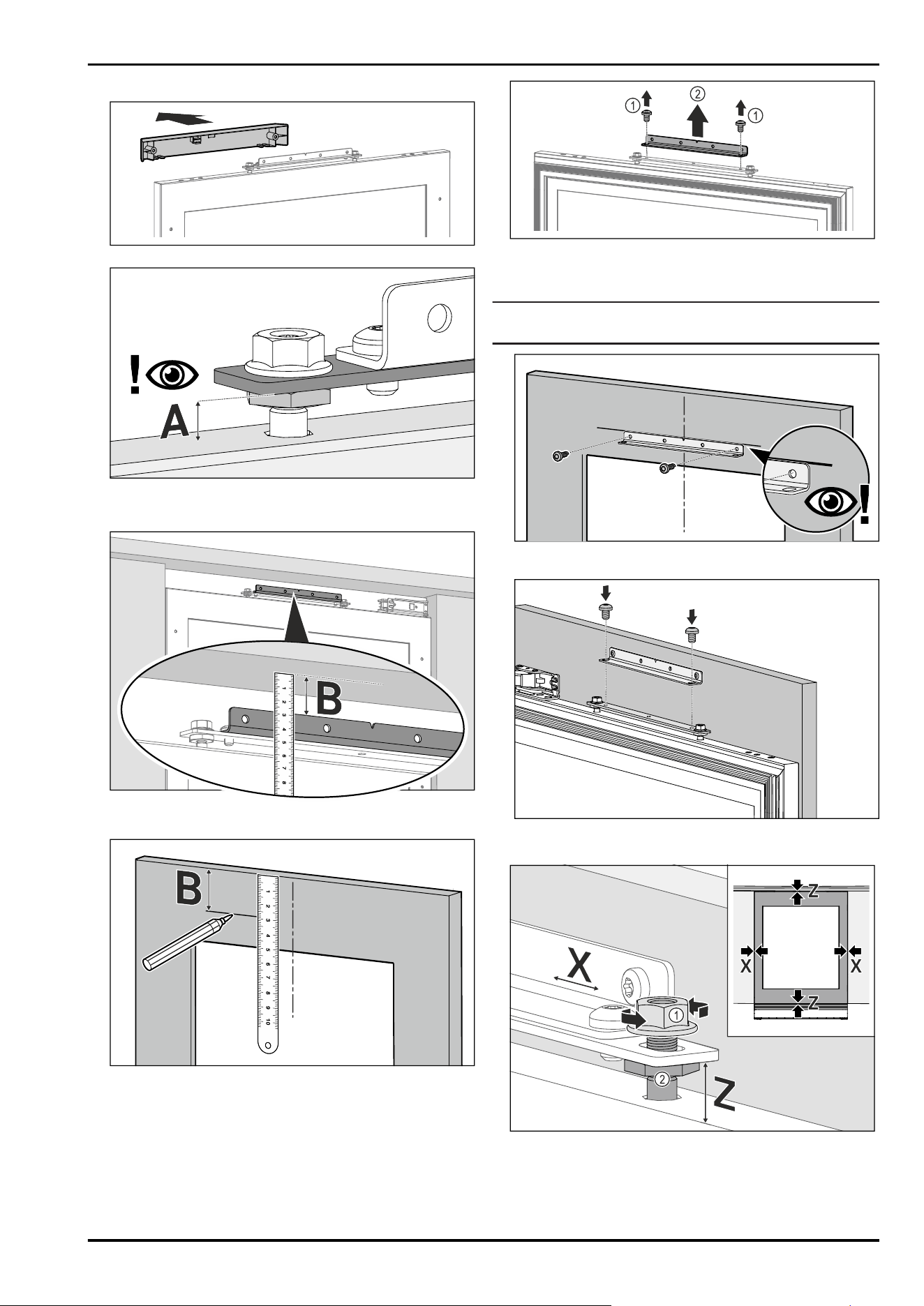
► Remove cover.
► Check the pre-setting (A) 8mm (distance between appli‐
ance door and lower edge of mounting plate).
► Adjust the distance if necessary.
► Measure the distance (B) between the lower edge of the
worktop and the upper edge of the mounting bracket.
► Transfer the distance (B) to the back of the unit door and
mark it.
Fig. 103
► Remove the screws. Fig. 103(1)
► Remove the mounting bracket. Fig. 103(2)
Note
Pay attention to the length of the screws!
► Align the mounting bracket with the marked distance and
screw it to the centre of the unit door.
► Attach the unit door to the appliance.
► Close the door.
Fig. 104
► Check the distance of the door against the surrounding
unit doors.
► Align the unit door sideways: Loosen lock nut Fig. 104(1),
move unit door in X direction.
Fitting the unit door
26 * Depending on model and options
► Tighten the lock nuts Fig. 104(1).
► Align the unit door in height Z and in the lateral inclina‐
tion: Adjust the adjustment bolt Fig. 104(2).
▷ The unit door is aligned flush with the surrounding unit
doors.
Note
Pay attention to the length of the screws!
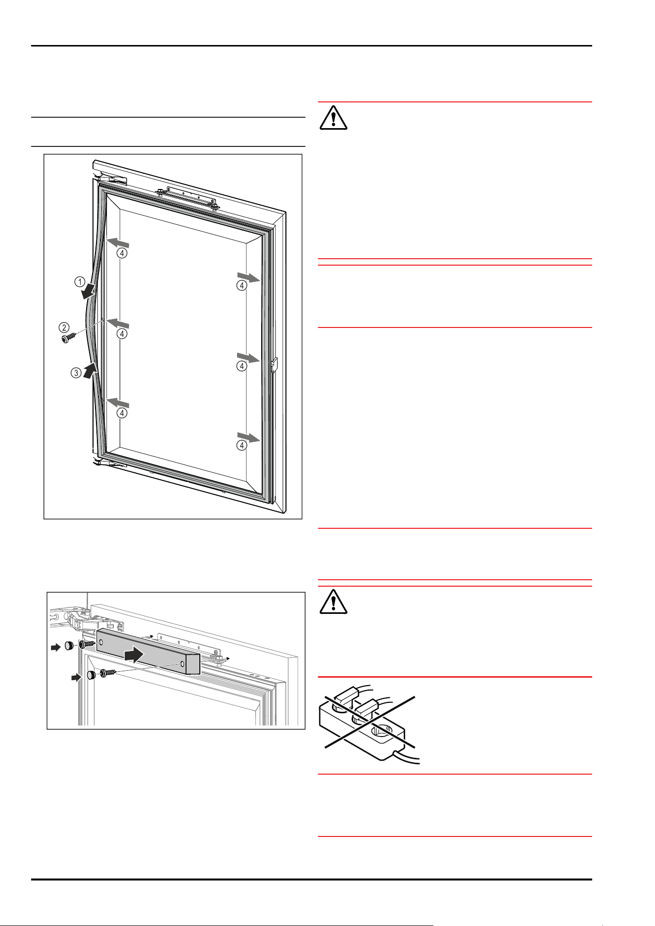
Fig. 105
► Loosen the magnetic door seal at certain points
Fig. 105(1), screw on the unit door through the drill hole
underneath Fig. 105(2) and snap the magnetic door seal
back into place Fig. 105(3).
► Repeat this step at all fastening points Fig. 105(4).
► Fit and screw on the top cover to ensure proper closing
function.
17 Connecting the appliance to the
power supply
WARNING
Danger of electric shock and injury due to damaged appli‐
ance or damaged mains cable!
Danger of cuts and fatal injuries. If the appliance or the
mains cable is damaged during transport, you may be elec‐
trocuted. You could also cut yourself on damaged parts of
the appliance housing.
► Check the appliance and the mains cable for damage
after transport.
► Never put the appliance into operation if the appliance or
the mains cable are damaged.
► Contact Customer Service.
NOTICE
Risk of injury and damage due to incorrect operation!*
Burns.
Damage to the electrical components of the appliance.
► Always operate the appliance with a voltage stabiliser.
You can connect your appliance to the mains using the
power cable supplied separately. The mains power cable
has an appliance coupler at one end and a mains plug at the
other end.
Make sure that the following requirements are fulfilled:
-
The appliance and power cable are undamaged.
-
The appliance is installed in accordance with the regula‐
tions. (see 15 Recessed installation)
-
Requirements for the electrical connection are met.
-
Dimensions for connection in accordance with regula‐
tions are known and observed.
-
Mains voltage and frequency correspond to the specifica‐
tions on the type plate.
-
The socket is earthed according to the regulations and
fused.
-
The fuse tripping current is between 10A and 16A.
NOTICE
Danger of damage to incorrect operation!
Damage to the electrical components of the appliance.
► Only use the supplied mains cable.
WARNING
Danger of fire due to incorrect connection!
Burns.
Damage to the appliance.
► Do not use an extension cable.
► Do not use distributor blocks.
NOTICE
Danger of damage to incorrect connection!
Damage to the appliance.
► Do not connect the appliance to a stand-alone inverter,
e.g. solar power systems and petrol generators.
► Connect the mains cable plug to the power supply.
Ensure that the plug is tightly in the socket.
Connecting the appliance to the power supply
* Depending on model and options 27

▷ If no action occurs within 60 seconds: The standby
symbol fades or disappears.*
▷ The appliance is connected. For information regarding
first use, see the following section or the operating
instructions.
Connecting the appliance to the power supply
28 * Depending on model and options

Connecting the appliance to the power supply
* Depending on model and options 29
home.liebherr.com/fridge-manuals
integrated wine fridges
Issue date: 20260511
Part number index:7088596-00
Liebherr-Hausgeräte GmbH
Memminger Straße 77-79
88416Ochsenhausen
Deutschland