Owners Manual
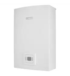
ES20CF-2-NG / ES26CF-2-NG
Envirosun
®
Endless Series Gas Water Heater
WM-022861
AS 3498
IMK22861
AS/NZS 2712
manual_2025_A20-A26_HPW3.indd 1manual_2025_A20-A26_HPW3.indd 1 18/03/2025 12:40:37 PM18/03/2025 12:40:37 PM
INSTALLATION RECORD
PLEASE COMPLETE THIS PAGE AS A RECORD OF THE INSTALLATION DETAILS FOR YOUR REFERENCE TO
DETERMINE WHEN THE SYSTEM IS DUE FOR SERVICE OR IF A WARRANTY MATTER SHOULD ARISE.
SCAN THE QR CODE WITH YOUR PHONE AND REGISTER YOUR WARRANTY ONLINE.
Energie Group Pty Ltd
ABN 50 166 500 787
460 Victoria Road
Malaga WA 6090
IMPORTANT!
REGISTER YOUR
WARRANTY
....................................................................................................................................................................................................................................
Owner Name
....................................................................................................................................................................................................................................
Installation Address
..............................................................................................................
Suburb
..................................................................................................................
State
.....................................................
Telephone (Home)
.....................................................
(Work)
..................................................................................................................
Email
............... / ............... / .................
Install Date
............................................................................................................
System Model Number
........................................................................................................
Serial Number
....................................................................................................................................................................................................................................
Installer Name
....................................................................................................................................................................................................................................
Installer Address
..............................................................................................................
Installer Telephone
....................................................................................................................................................................................................................................
....................................................................................................................................................................................................................................
Comments
..............................................................................................................
Customer Signature
..................................................................................................................
Installer Signature
............... / ............... / ....................
Date
envirosun.au/warranty
manual_2025_A20-A26_HPW3.indd 2manual_2025_A20-A26_HPW3.indd 2 18/03/2025 12:40:37 PM18/03/2025 12:40:37 PM

ver 250318.12
Page 1 of 14
CONTENTS
IMPORTANT NOTES �������������������������������������������������������������������������������������������������������������������������������������������������������������������������������������������������������������� 2
Installation notes ......................................................................................................................................................................................................... 2
Service notes ............................................................................................................................................................................................................... 2
Gas water heater maintenance ................................................................................................................................................................................... 2
Water quality ............................................................................................................................................................................................................... 3
Plumbing notes ........................................................................................................................................................................................................... 3
SPECIFICATIONS ���������������������������������������������������������������������������������������������������������������������������������������������������������������������������������������������������������������������� 4
INITIAL OPERATION �������������������������������������������������������������������������������������������������������������������������������������������������������������������������������������������������������������� 5
Operation process of gas water heater ........................................................................................................................................................................ 5
NORMAL OPERATION ���������������������������������������������������������������������������������������������������������������������������������������������������������������������������������������������������������� 6
Normal operation ......................................................................................................................................................................................................... 7
Series-connected solar energy ..................................................................................................................................................................................... 7
MAINTENANCE AND SERVICE ����������������������������������������������������������������������������������������������������������������������������������������������������������������������������������������� 8
Unit draining and lter cleaning ................................................................................................................................................................................... 8
General troubleshooting .............................................................................................................................................................................................. 9
Error codes ................................................................................................................................................................................................................ 10
The following conditions are not a fault ..................................................................................................................................................................... 11
Packing List ............................................................................................................................................................................................................... 11
STANDARD WARRANTY �������������������������������������������������������������������������������������������������������������������������������������������������������������������������������������������������� 12
Warranty Terms ......................................................................................................................................................................................................... 12
Warranty Conditions .................................................................................................................................................................................................. 12
Warranty Exclusions .................................................................................................................................................................................................. 13
OH&S Disclaimer ....................................................................................................................................................................................................... 14
CONTACT DETAILS �������������������������������������������������������������������������������������������������������������������������������������������������������������������������������������������������������������� 14
manual_2025_A20-A26_HPW3.indd 1manual_2025_A20-A26_HPW3.indd 1 18/03/2025 12:40:37 PM18/03/2025 12:40:37 PM
Page 2 of 14
ver 250318.12
IMPORTANT NOTES
This manual has been prepared for the relevant licensed professionals of the equipment. Please keep it in a safe place for future reference.
INSTALLATION NOTES
The installation must be done by a qualied person and in accordance with the information supplied in this manual. Installation must conform with
Plumbing Code of Australia (PCA) .
All other relevant national, state and local regulations must also be adhered to including (but are not limited to):
• Australian Standard AS3500.1 – Water Services
• Australian Standard AS3500.4 – Heated Water Services
• Australian Standard AS3000 – Electrical Installation
• Australian Standard AS/NZS5601 – Gas Appliance Installation
• All Local Water, Gas & Electrical Authority Regulations
• Municipal Building Codes including local OH&S requirements
SERVICE NOTES
Maintenance and fault-nding must be done in accordance with these instructions and the applicable regulations listed above.
GAS WATER HEATER MAINTENANCE
It is recommended to maintain the gas water heater for ≥1 times a year. Please contact your local dealer for maintenance. Do not disassemble the
gas water heater without permission.
WARNING
INSTALLATION AND SERVICE SHALL BE CARRIED OUT ONLY BY AUTHORISED PERSONNEL (FOR EXAMPLE A
LICENSED PLUMBER OR GAS FITTER) AND THE APPLIANCE SHALL NOT BE MODIFIED.
FOR CONTINUED SAFETY OF THIS APPLIANCE IT MUST BE INSTALLED, OPERATED AND MAINTAINED IN
ACCORDANCE WITH THE MANUFACTURER’S INSTRUCTIONS.
WARNING ABOUT HOT WATER
Heated water can be dangerous, especially for young children and the inrm. Water temperatures
above 50°C can cause severe burns instantly and may even result in death. Those most at risk are
children, disabled, elderly and the inrm.
Hot water at 60°C can severely burn a child in less than half a second, at 50°C it takes ve minutes.
ALWAYS
Always test the temperature of the water
with your elbow before placing a child in
the bath; also carefully feel water before
bathing or showering yourself. Supervise
children whenever they are in the
bathroom. Make sure that the hot water
tap is turned off tightly.
CONSIDER
Consider installing child proof tap covers
or child resistant taps (both approaches
will prevent a small hand being able to turn
on the tap), and setting the appliance at a
maximum temperature of 50°C.
NEVER
Never leave a toddler in the care of
another child. They may not understand
the need to have the water temperature set
at a safe level.
manual_2025_A20-A26_HPW3.indd 2manual_2025_A20-A26_HPW3.indd 2 18/03/2025 12:40:38 PM18/03/2025 12:40:38 PM
ver 250318.12
Page 3 of 14
WATER QUALITY
Water supply from an unltered water source that may be highly conductive or have a high mineral content may void the system warranty. Therefore,
to ensure water quality guidelines are met, the following characteristics should not be exceeded.
Water Properties Acceptable Levels
Total hardness 200 mg/litre or ppm
Total Dissolved Solids (TDS) 600 mg/litre or ppm
Chloride 250 mg/litre or ppm
Magnesium 10 mg/litre or ppm
Sodium 150 mg/litre or ppm
pH Min 6.5 to Max 8 .5
Electrical conductivity 850 μS/cm
In areas of poor water quality, it is recommended that a softener, conditioner or similar device be tted to the water supply.
WARNING
A breach of this condition may void the warranty in the event of damage caused by water quality
exceeding these characteristics.
PLUMBING NOTES
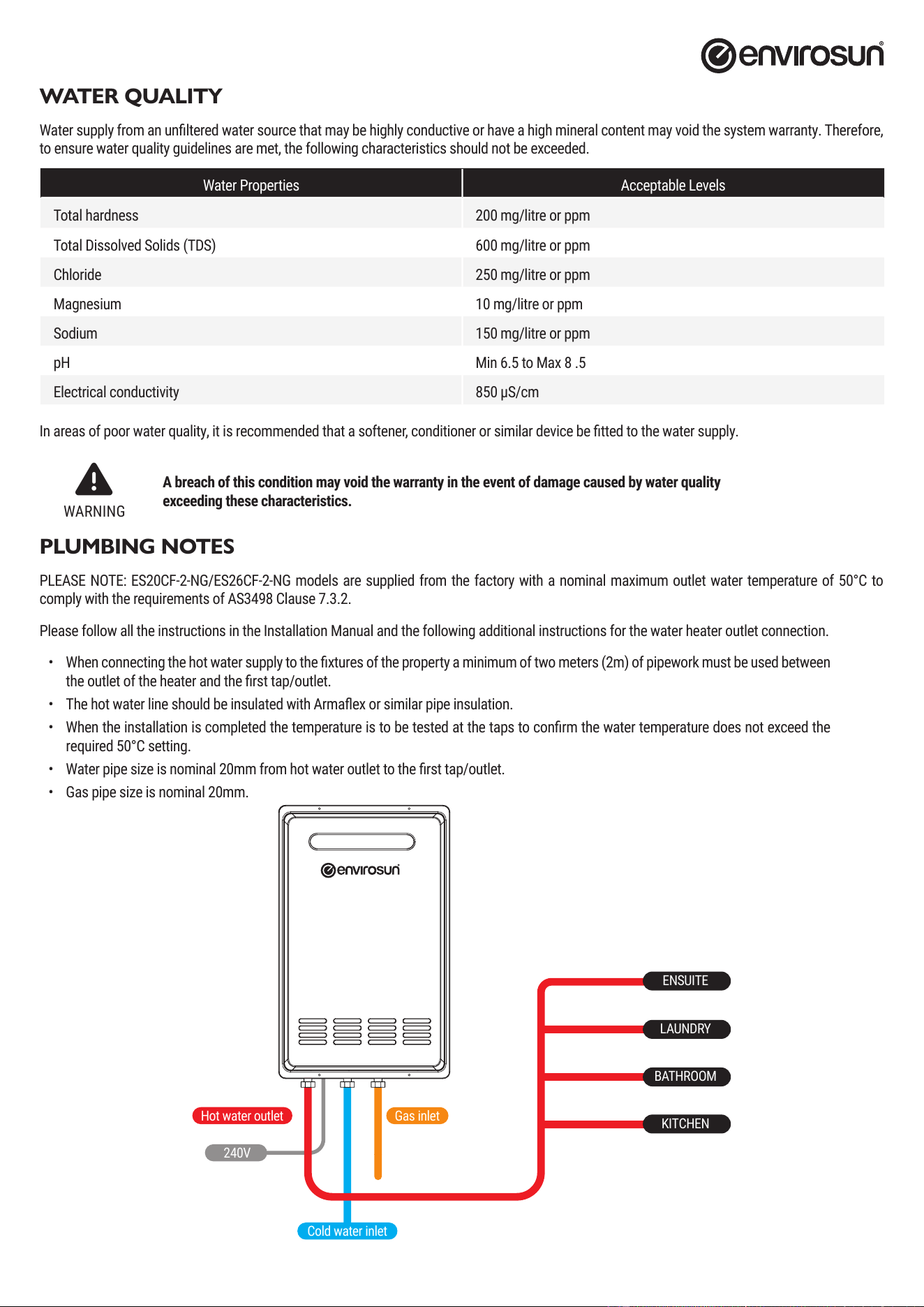
PLEASE NOTE: ES20CF-2-NG/ES26CF-2-NG models are supplied from the factory with a nominal maximum outlet water temperature of 50°C to
comply with the requirements of AS3498 Clause 7.3.2.
Please follow all the instructions in the Installation Manual and the following additional instructions for the water heater outlet connection.
• When connecting the hot water supply to the xtures of the property a minimum of two meters (2m) of pipework must be used between
the outlet of the heater and the rst tap/outlet.
• The hot water line should be insulated with Armaex or similar pipe insulation.
• When the installation is completed the temperature is to be tested at the taps to conrm the water temperature does not exceed the
required 50°C setting.
• Water pipe size is nominal 20mm from hot water outlet to the rst tap/outlet.
• Gas pipe size is nominal 20mm.
ENSUITE
LAUNDRY
BATHROOM
KITCHEN
Gas inlet
240V
Hot water outlet
Cold water inlet
manual_2025_A20-A26_HPW3.indd 3manual_2025_A20-A26_HPW3.indd 3 18/03/2025 12:40:38 PM18/03/2025 12:40:38 PM
Page 4 of 14
ver 250318.12
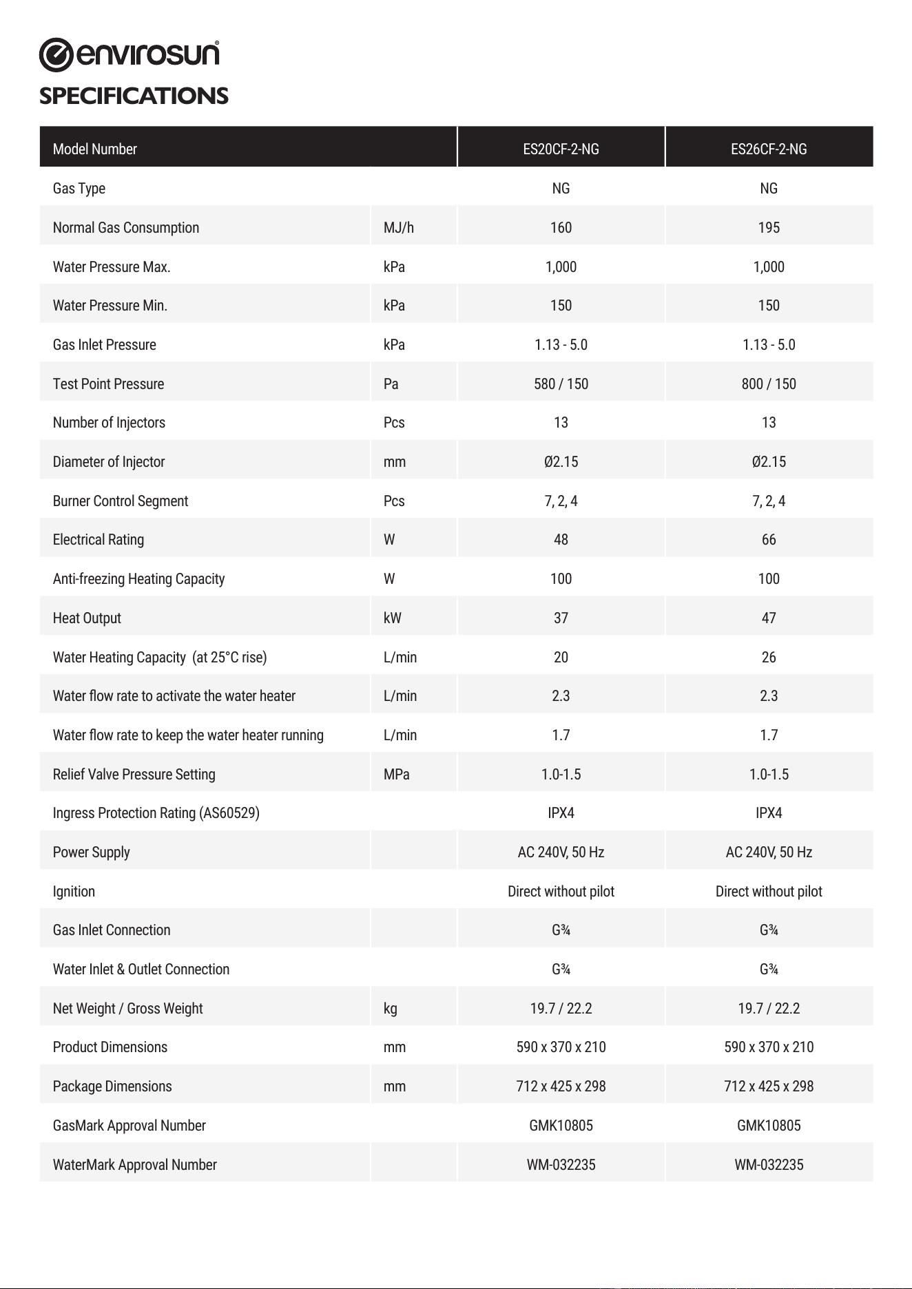
SPECIFICATIONS
Model Number ES20CF-2-NG ES26CF-2-NG
Gas Type NG NG
Normal Gas Consumption MJ/h 160 195
Water Pressure Max. kPa 1,000 1,000
Water Pressure Min. kPa 150 150
Gas Inlet Pressure kPa 1.13 - 5.0 1.13 - 5.0
Test Point Pressure Pa 580 / 150 800 / 150
Number of Injectors Pcs 13 13
Diameter of Injector mm Ø2.15 Ø2.15
Burner Control Segment Pcs 7, 2, 4 7, 2, 4
Electrical Rating W 48 66
Anti-freezing Heating Capacity W 100 100
Heat Output kW 37 47
Water Heating Capacity (at 25°C rise) L/min 20 26
Water ow rate to activate the water heater L/min 2.3 2.3
Water ow rate to keep the water heater running L/min 1.7 1.7
Relief Valve Pressure Setting MPa 1.0-1.5 1.0-1.5
Ingress Protection Rating (AS60529) IPX4 IPX4
Power Supply AC 240V, 50 Hz AC 240V, 50 Hz
Ignition Direct without pilot Direct without pilot
Gas Inlet Connection G¾ G¾
Water Inlet & Outlet Connection G¾ G¾
Net Weight / Gross Weight kg 19.7 / 22.2 19.7 / 22.2
Product Dimensions mm 590 x 370 x 210 590 x 370 x 210
Package Dimensions mm 712 x 425 x 298 712 x 425 x 298
GasMark Approval Number GMK10805 GMK10805
WaterMark Approval Number WM-032235 WM-032235
manual_2025_A20-A26_HPW3.indd 4manual_2025_A20-A26_HPW3.indd 4 18/03/2025 12:40:38 PM18/03/2025 12:40:38 PM
ver 250318.12
Page 5 of 14
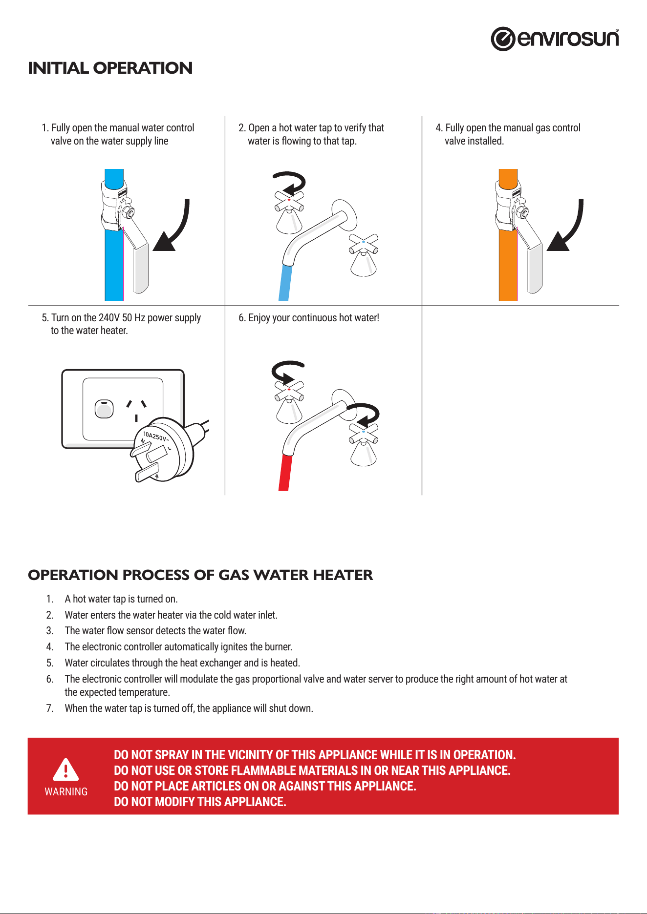
INITIAL OPERATION
1. Fully open the manual water control
valve on the water supply line
2. Open a hot water tap to verify that
water is owing to that tap.
4. Fully open the manual gas control
valve installed.
5. Turn on the 240V 50 Hz power supply
to the water heater.
6. Enjoy your continuous hot water!
OPERATION PROCESS OF GAS WATER HEATER
1. A hot water tap is turned on.
2. Water enters the water heater via the cold water inlet.
3. The water ow sensor detects the water ow.
4. The electronic controller automatically ignites the burner.
5. Water circulates through the heat exchanger and is heated.
6. The electronic controller will modulate the gas proportional valve and water server to produce the right amount of hot water at
the expected temperature.
7. When the water tap is turned off, the appliance will shut down.
WARNING
DO NOT SPRAY IN THE VICINITY OF THIS APPLIANCE WHILE IT IS IN OPERATION.
DO NOT USE OR STORE FLAMMABLE MATERIALS IN OR NEAR THIS APPLIANCE.
DO NOT PLACE ARTICLES ON OR AGAINST THIS APPLIANCE.
DO NOT MODIFY THIS APPLIANCE.
manual_2025_A20-A26_HPW3.indd 5manual_2025_A20-A26_HPW3.indd 5 18/03/2025 12:40:39 PM18/03/2025 12:40:39 PM
Page 6 of 14
ver 250318.12
NORMAL OPERATION
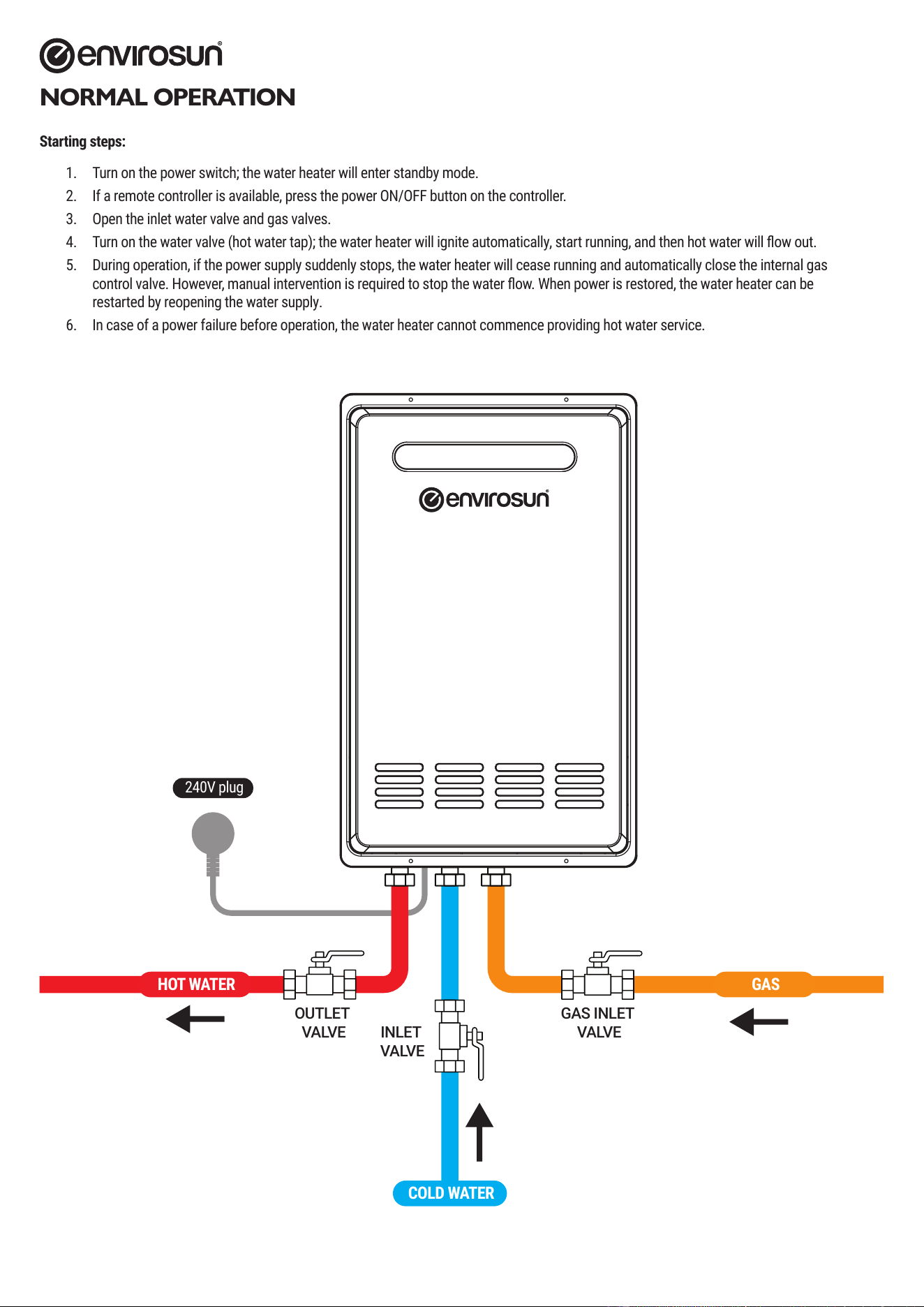
Starting steps:
1. Turn on the power switch; the water heater will enter standby mode.
2. If a remote controller is available, press the power ON/OFF button on the controller.
3. Open the inlet water valve and gas valves.
4. Turn on the water valve (hot water tap); the water heater will ignite automatically, start running, and then hot water will ow out.
5. During operation, if the power supply suddenly stops, the water heater will cease running and automatically close the internal gas
control valve. However, manual intervention is required to stop the water ow. When power is restored, the water heater can be
restarted by reopening the water supply.
6. In case of a power failure before operation, the water heater cannot commence providing hot water service.
240V plug
GAS INLET
VALVEINLET
VA LVE
OUTLET
VA LVE
GASHOT WATER
COLD WATER
manual_2025_A20-A26_HPW3.indd 6manual_2025_A20-A26_HPW3.indd 6 18/03/2025 12:40:39 PM18/03/2025 12:40:39 PM
ver 250318.12
Page 7 of 14
NORMAL OPERATION
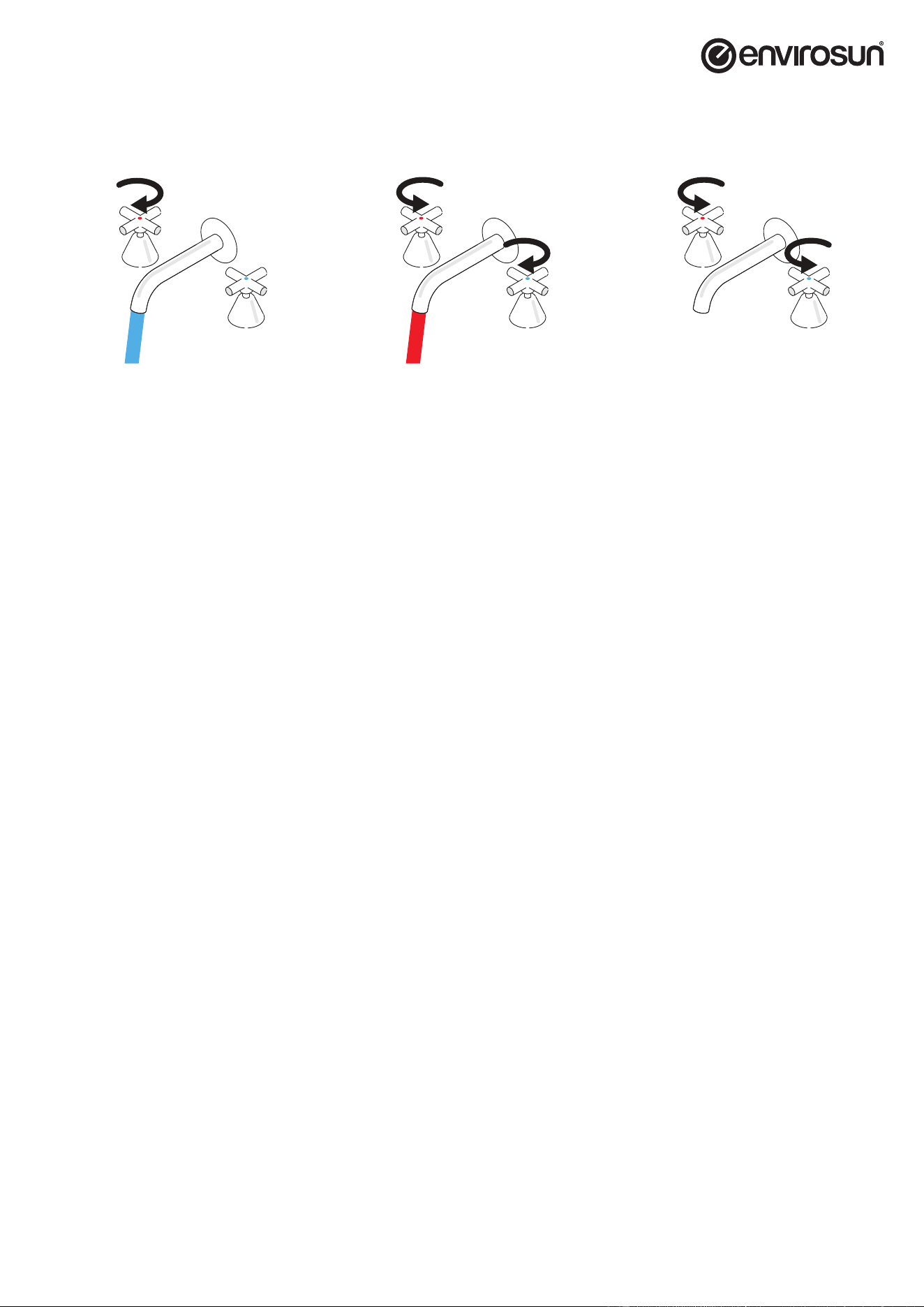
1. Open a hot water tap.
2. Mix cold water with the hot to get
the correct temperature water.
3. Close the water taps.
SERIES-CONNECTED SOLAR ENERGY
The ES20CF-2-NG and ES26CF-2-NG models can be connected with solar energy in series.
• The wire controller should not be installed when solar energy is connected in series.
• In the Australian market, the gas water heater (GWH) is connected in series with the solar energy system. GW is only an accessory of
solar energy, named “gas booster,” and its main system is solar energy. The preset temperature of the water outlet of the gas water
heater is 70℃.
• The gas water heater will not ignite when the water inlet pipe of the gas water heater is connected with the water outlet pipe of solar
energy, and the water inlet temperature of the gas water heater is higher than or equal to 58℃; start burning when the temperature of
the inlet water is lower than 58℃; stop burning for 10 seconds continuously when the temperature of the inlet water is higher than or
equal to 60℃;
• Special requirements for connecting solar energy in series:
1. The gas water heater is used as a supplementary device for heat sources, and the burning stops after burning for 1 hour, and the
burning can be started by switching on and off the water again;
2. In the case of minimum load burning, stop the burning when the temperature of the outlet water is ≥ the set temperature +3℃ for
20s or the temperature of the outlet water is ≥78.5℃; burning can be started by switching on and off the water and the device
again;
3. To prevent scalding by hot water, the actual temperature of the outlet water is associated with the water ow and temperature of
the inlet water. Please conrm the temperature of hot water by hand before using it;
4. The ex-factory temperature is 50℃, and the highest temperature is 75℃. The temperature of 70℃ can be adjusted by a qualied
installer to connect solar energy in series (bacteria legion killing), and the wire controller cannot be used when connecting
solar energy in series. Furthermore, the temperature of the surface cover can be lowered by a qualied installer, and the set
temperatures are 75, 70, 65, 60, 55, 50, 48, 45, 43, 42, 40, and 38.
5. When connecting solar energy in series, E4 fault will be reported in case the temperature of the inlet water or the temperature of
the outlet water is beyond 90 degrees.
6. When connecting solar energy in series, the mode of connecting solar energy in series will be started by default when the set
temperature is greater than 70 degrees.
Freeze prevention
WARNING
If freezing conditions are expected, turn off water / gas supply and drain the water from the appliance.
• Turn off the water supply valve;
• Turn off the gas supply valve;
• Turn off the power supply switch;
• Drain the water from the water heater (refer to p.19).
If power supply is on, and the automatic anti-freezing protection system will be running and the freezing will be prevented. Only the pipes and heat
exchanger inside the water heater will be protected. Any hot or cold water pipes located outside of the unit will not be protected. Proper protection
and insulation of these pipes will be required to ensure these are protected from freezing.
manual_2025_A20-A26_HPW3.indd 7manual_2025_A20-A26_HPW3.indd 7 18/03/2025 12:40:39 PM18/03/2025 12:40:39 PM
Page 8 of 14
ver 250318.12
MAINTENANCE AND SERVICE
The water heater should be checked at least once a year or as necessary by a licensed technician. If repairs are needed, any repairs should be done
by a licensed technician. The water heater’s lifetime may be extended by regular maintenance.
• Please Contact Customer Service on +61 8 9203 2000 for service.
• Provide the serial number and model number of the water heater. This can be found on the compliance plate on the right side of the unit.
• Provide your full name, address and contact number.
WARNING
• Service Shall Be Carried Out Only By Authorized Personnel and the Appliance Shall Not Be Modied.
• The Appliance Must Be Installed, Commissioned And Serviced By An Authorized Person In Accordance With
The Requirements Of AS/NZS 3500.42.
• Turn off the electrical power supply and close the manual gas control valve and the manual water control
valve before servicing.
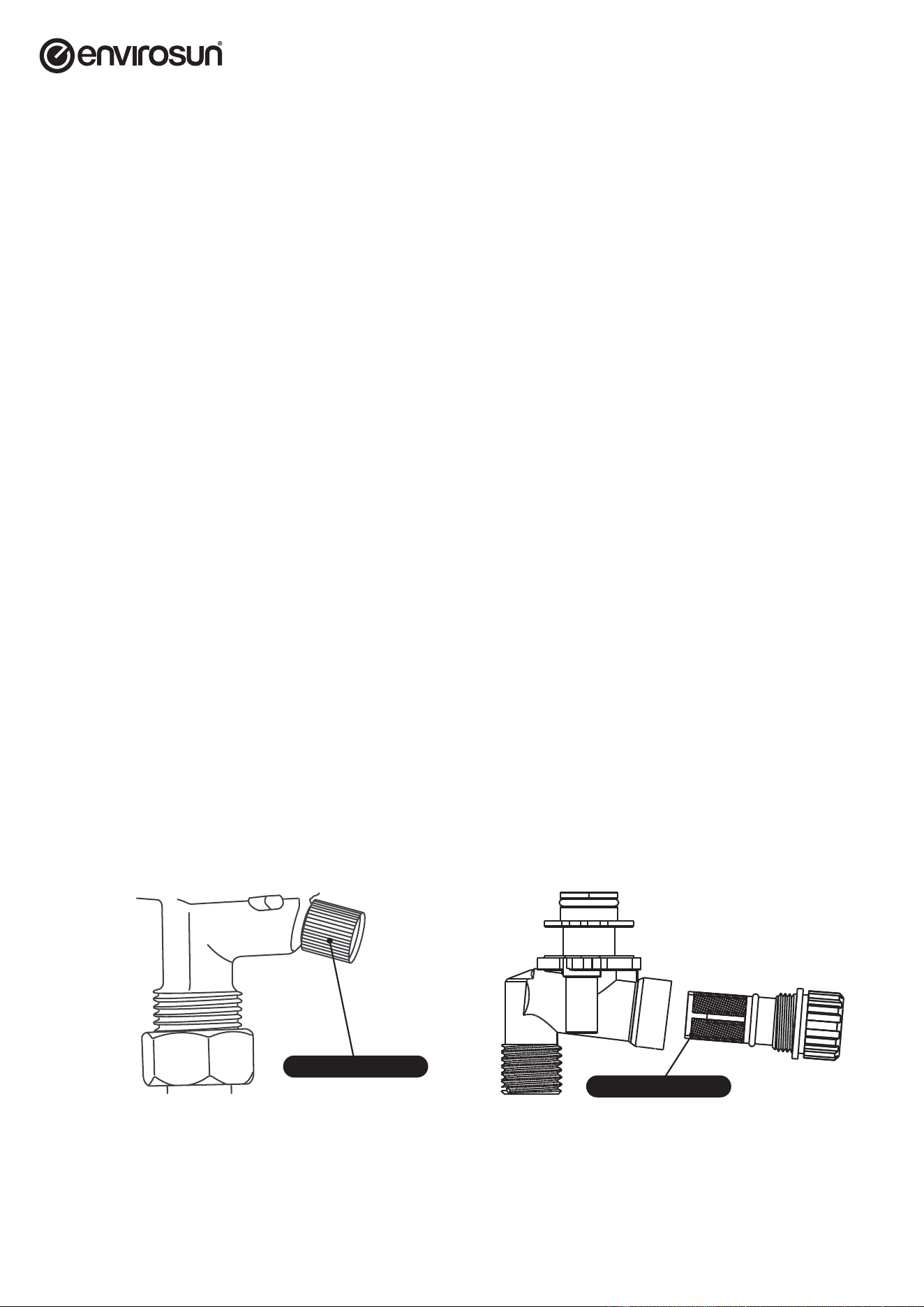
1. Clean the cold-water inlet lter (refer to diagram below).
2. Be sure that all openings for combustion air are not blocked. If blocked, remove obstruction.
3. Check that the opening for exhaust is not blocked. If blocked, shutoff the water heater’s operation. And
then after a while, remove obstruction. DO NOT touch while unit operating, otherwise you might get burnt
due to high temperature.
4. Check the gas pressure and if necessary adjust the gas pressure.
5. Inspect all connections.
6. Check and clean the line strainer.
7. Keep the area around the water heater clear. Remove any combustible materials, gasoline or any
ammable vapors and liquids.
UNIT DRAINING AND FILTER CLEANING
• Close the manual gas shut off valve and the manual water shut off valve.
• Turn off the power supply to the water heater.
• Open a hot water taps in the house (preferably the shower outlet).
• Prepare a bucket or container to catch the water from the unit’s drain plugs. Unscrew the pressure relief valve located in the hot water
outlet and the lter located in the cold water inlet to drain the water from the appliance.
• Wait a few minutes to ensure all water has completely drained from unit. When water stops, close the hot tap.
• Clean the lter: With a tiny brush, clean the water lter of any debris which may have accumulated and then screw the lter back into
the cold water inlet.
• Securely screw the pressure relief valve back into the hot water outlet, tighten it by hand only.
Pressure Relief Valve
Filter Screen
REMOVE BY TURNING COUNTER CLOCKWISE
AND THEN CLEAN OR REPLACE.
manual_2025_A20-A26_HPW3.indd 8manual_2025_A20-A26_HPW3.indd 8 18/03/2025 12:40:39 PM18/03/2025 12:40:39 PM
ver 250318.12
Page 9 of 14
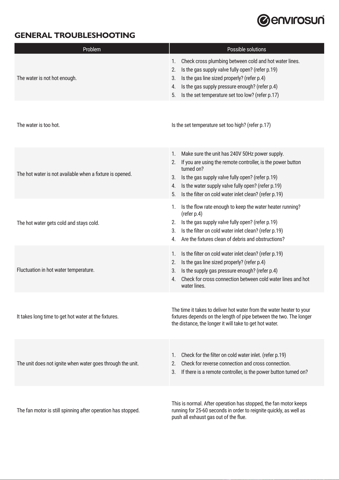
GENERAL TROUBLESHOOTING
Problem Possible solutions
The water is not hot enough.
1. Check cross plumbing between cold and hot water lines.
2. Is the gas supply valve fully open? (refer p.19)
3. Is the gas line sized properly? (refer p.4)
4. Is the gas supply pressure enough? (refer p.4)
5. Is the set temperature set too low? (refer p.17)
The water is too hot. Is the set temperature set too high? (refer p.17)
The hot water is not available when a xture is opened.
1. Make sure the unit has 240V 50Hz power supply.
2. If you are using the remote controller, is the power button
turned on?
3. Is the gas supply valve fully open? (refer p.19)
4. Is the water supply valve fully open? (refer p.19)
5. Is the lter on cold water inlet clean? (refer p.19)
The hot water gets cold and stays cold.
1. Is the ow rate enough to keep the water heater running?
(refer p.4)
2. Is the gas supply valve fully open? (refer p.19)
3. Is the lter on cold water inlet clean? (refer p.19)
4. Are the xtures clean of debris and obstructions?
Fluctuation in hot water temperature.
1. Is the lter on cold water inlet clean? (refer p.19)
2. Is the gas line sized properly? (refer p.4)
3. Is the supply gas pressure enough? (refer p.4)
4. Check for cross connection between cold water lines and hot
water lines.
It takes long time to get hot water at the xtures.
The time it takes to deliver hot water from the water heater to your
xtures depends on the length of pipe between the two. The longer
the distance, the longer it will take to get hot water.
The unit does not ignite when water goes through the unit.
1. Check for the lter on cold water inlet. (refer p.19)
2. Check for reverse connection and cross connection.
3. If there is a remote controller, is the power button turned on?
The fan motor is still spinning after operation has stopped.
This is normal. After operation has stopped, the fan motor keeps
running for 25-60 seconds in order to reignite quickly, as well as
push all exhaust gas out of the ue.
manual_2025_A20-A26_HPW3.indd 9manual_2025_A20-A26_HPW3.indd 9 18/03/2025 12:40:39 PM18/03/2025 12:40:39 PM
Page 10 of 14
ver 250318.12
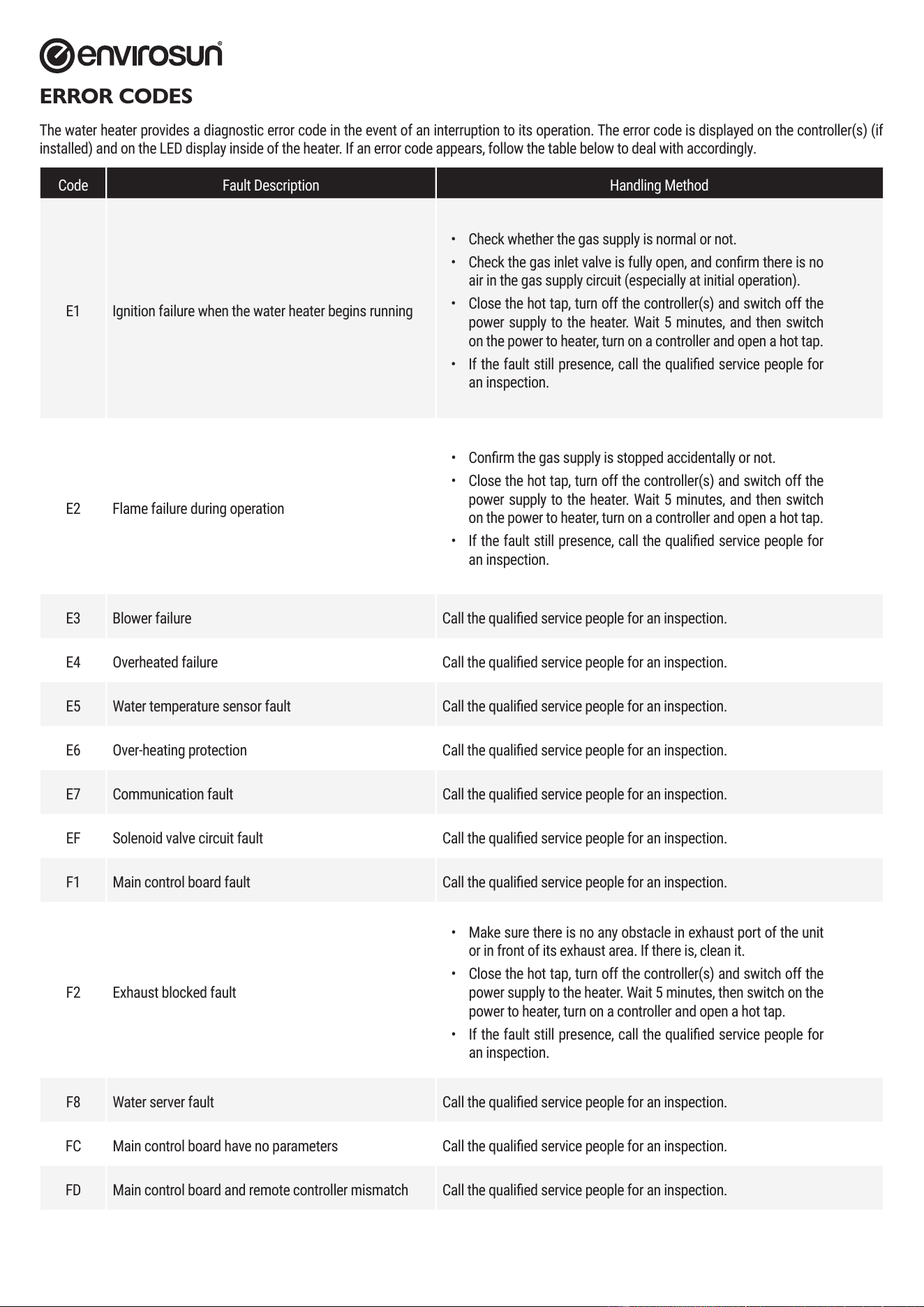
ERROR CODES
The water heater provides a diagnostic error code in the event of an interruption to its operation. The error code is displayed on the controller(s) (if
installed) and on the LED display inside of the heater. If an error code appears, follow the table below to deal with accordingly.
Code Fault Description Handling Method
E1 Ignition failure when the water heater begins running
• Check whether the gas supply is normal or not.
• Check the gas inlet valve is fully open, and conrm there is no
air in the gas supply circuit (especially at initial operation).
• Close the hot tap, turn off the controller(s) and switch off the
power supply to the heater. Wait 5 minutes, and then switch
on the power to heater, turn on a controller and open a hot tap.
• If the fault still presence, call the qualied service people for
an inspection.
E2 Flame failure during operation
• Conrm the gas supply is stopped accidentally or not.
• Close the hot tap, turn off the controller(s) and switch off the
power supply to the heater. Wait 5 minutes, and then switch
on the power to heater, turn on a controller and open a hot tap.
• If the fault still presence, call the qualied service people for
an inspection.
E3 Blower failure Call the qualied service people for an inspection.
E4 Overheated failure Call the qualied service people for an inspection.
E5 Water temperature sensor fault Call the qualied service people for an inspection.
E6 Over-heating protection Call the qualied service people for an inspection.
E7 Communication fault Call the qualied service people for an inspection.
EF Solenoid valve circuit fault Call the qualied service people for an inspection.
F1 Main control board fault Call the qualied service people for an inspection.
F2 Exhaust blocked fault
• Make sure there is no any obstacle in exhaust port of the unit
or in front of its exhaust area. If there is, clean it.
• Close the hot tap, turn off the controller(s) and switch off the
power supply to the heater. Wait 5 minutes, then switch on the
power to heater, turn on a controller and open a hot tap.
• If the fault still presence, call the qualied service people for
an inspection.
F8 Water server fault Call the qualied service people for an inspection.
FC Main control board have no parameters Call the qualied service people for an inspection.
FD Main control board and remote controller mismatch Call the qualied service people for an inspection.
manual_2025_A20-A26_HPW3.indd 10manual_2025_A20-A26_HPW3.indd 10 18/03/2025 12:40:39 PM18/03/2025 12:40:39 PM
ver 250318.12
Page 11 of 14
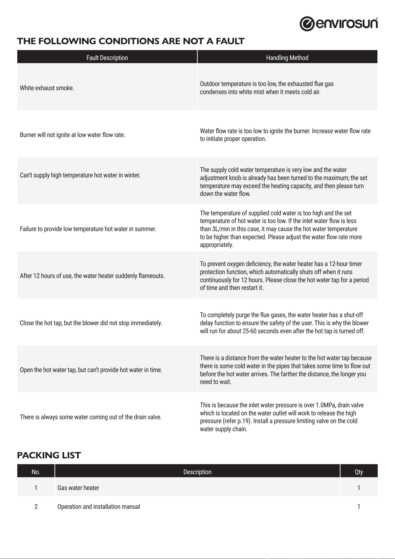
THE FOLLOWING CONDITIONS ARE NOT A FAULT
Fault Description Handling Method
White exhaust smoke.
Outdoor temperature is too low, the exhausted ue gas
condenses into white mist when it meets cold air.
Burner will not ignite at low water ow rate.
Water ow rate is too low to ignite the burner. Increase water ow rate
to initiate proper operation.
Can’t supply high temperature hot water in winter.
The supply cold water temperature is very low and the water
adjustment knob is already has been turned to the maximum; the set
temperature may exceed the heating capacity, and then please turn
down the water ow.
Failure to provide low temperature hot water in summer.
The temperature of supplied cold water is too high and the set
temperature of hot water is too low. If the inlet water ow is less
than 3L/min in this case, it may cause the hot water temperature
to be higher than expected. Please adjust the water ow rate more
appropriately.
After 12 hours of use, the water heater suddenly ameouts.
To prevent oxygen deciency, the water heater has a 12-hour timer
protection function, which automatically shuts off when it runs
continuously for 12 hours. Please close the hot water tap for a period
of time and then restart it.
Close the hot tap, but the blower did not stop immediately.
To completely purge the ue gases, the water heater has a shut-off
delay function to ensure the safety of the user. This is why the blower
will run for about 25-60 seconds even after the hot tap is turned off.
Open the hot water tap, but can’t provide hot water in time.
There is a distance from the water heater to the hot water tap because
there is some cold water in the pipes that takes some time to ow out
before the hot water arrives. The farther the distance, the longer you
need to wait.
There is always some water coming out of the drain valve.
This is because the inlet water pressure is over 1.0MPa, drain valve
which is located on the water outlet will work to release the high
pressure (refer p.19). Install a pressure limiting valve on the cold
water supply chain.
PACKING LIST
No. Description Qty
1 Gas water heater 1
2 Operation and installation manual 1
manual_2025_A20-A26_HPW3.indd 11manual_2025_A20-A26_HPW3.indd 11 18/03/2025 12:40:39 PM18/03/2025 12:40:39 PM

Page 12 of 14
ver 250318.12
STANDARD WARRANTY
WARRANTY TERMS
This warranty is given by Energie Group Australia Pty Ltd in relation to Envirosun Hot Water Systems (the Product).
The benets conferred by this warranty are in addition to all other legal rights and remedies of the Customer in respect of the Product. Given
installation and application is in accordance with the manufacturer’s specications and instructions, the Product and components are warranted by
Envirosun
®
for the cost of labour and components in the event of defects arising from faulty materials and/or workmanship in accordance with the
warranty conditions and exclusions stated in this document.
Where the Product is installed outside the boundaries of a Capital City Metropolitan area or where the Product is installed outside a 25km radius of a
Envirosun Dealer business address, the cost of transport, insurance and travelling will be charged to the consumer.
For all new Product purchases through public sales auctions, internet and/or other electronic sales auctions or remote offerings, the warranty for the
Product is the responsibility of the dealer or reseller of the Product, and not of Envirosun.
Warranty of the Product will remain with the Product for the warranty coverage period.
WARRANTY CONDITIONS
The initial point of contact for all Warranty claims is the Envirosun Dealer from whom the Product was purchased.
All warranty claims must be reported to Envirosun no later than 14 days from the date the fault is reported to the Envirosun Dealer. All terms of
this warranty are effective from the date of installation of the Product and the attending service person reserves the right to verify this date by
requesting a copy of the certicate of compliance
1
, installation record issued by an appropriately qualied installer or proof of purchase prior to the
commencement of any warranty work.
The Product must have been installed, commissioned, serviced, repaired and removed by a licensed gastter or plumber in accordance with the
manufacturer’s installation instructions, current AS/NZS 3000, AS/NZS 3500, AS/NZS 5601, local regulations and municipal building codes by
persons authorised by local regulations to do so. Cost of labour or materials to remedy an installation that does not comply with these requirements
will be at the express cost of the installer.
The Product must be operated and maintained in accordance with Envirosun’s operating instructions. This warranty only applies to the Product as
supplied by Envirosun and does not apply to any additional electrical and/or plumbing parts supplied by the installer. Where the appliance has not
been sited in accordance the installation instructions or installed such that normal service access is difcult, a service charge may apply. If, at the
discretion of the attending service person, access with is assessed as dangerous, service will be refused.
Any work required to gain reasonable access to the appliance will be chargeable to the customer by the attending service person including, but not
limited to, removal of cupboards, doors, walls, or the use of special equipment to move components to oor level.
The Product is covered for the indicated period from the date of installation. Should a part of the complete Product be replaced during this period,
only the balance of the original warranty will continue to remain effective.
This warranty applies to the Product when it is connected directly to a reticulated water supply from a state approved water utility.
This warranty does not apply if the Product is connected to any alternative water supplies if the water chemistry and impurity levels of alternative
water supplies exceed the limits specied in the Water Properties Table on p.3.
Examples of alternative water supplies include private bore water, water from private dams and water supplied from a reticulated water supply but
where the water chemistry is deliberately altered before supplying the water heater. Should the Product be installed in a regional location where
regular ushing is required due to sediment build-up, the drain cock for ushing must be tted at the time of installation at customer expense. A
warranty will apply to rain water tanks, as alternative water supply, ONLY in circumstances where rain water is ltered and free of any physical or
sediment debris and water quality does not exceed the limits specied in the Water Properties Table on p.3.
Component manufacturers are at liberty to alter the design or construction of the components notwithstanding that the Product may have been sold
by description or sample, even though alterations made have been introduced from the date of contract and the date of delivery provided that the
Products are of the same or similar quality and are t for the purposes for which they are purchased. Such alterations shall not constitute a defect in
design or construction under this warranty.
Envirosun reserves the right to alter the design or construction of the Product within allowance of the relevant Standard(s), industrial and State and
Territory legislation without notice. Envirosun warrants to the original purchaser, or for Product purchased from a Reseller, to the original end user,
that the Product will be free from any defects in materials and workmanship from the date of shipment or invoice or, if longer, the period stated in this
policy in accordance with the warranty terms in Table 2.
manual_2025_A20-A26_HPW3.indd 12manual_2025_A20-A26_HPW3.indd 12 18/03/2025 12:40:39 PM18/03/2025 12:40:39 PM
ver 250318.12
Page 13 of 14
During the warranty period, Envirosun will, at its option, apply one of the three following remedies:
i. provide replacement parts necessary to repair the Product,
ii. replace the Product with same Product or similar approved newer design,
iii. refund the amount purchaser paid, LESS DEPRECIATION, upon its return.
Envirosun or a Envirosun Dealer will provide labour to resolve warranty issues during the warranty period. Repair service shall be available at the
purchaser’s location. Envirosun will determine how and where repair services are provided, and the purchaser may, at Envirosun’s reasonable cost, be
required to deliver product to an authorised location.
Replacement parts and/or Products will be new or serviceably used, comparable in function and performance to the original part or Product and
warranted for the remainder of the original warranty period. Purchasing additional Products from Envirosun does not extend your warranty period.
If Envirosun requires the return of defective parts/Products, the Envirosun Dealer/purchaser shall return them within 14 days of receiving replacement
parts. Failure to return defective parts will attract charges for replaced parts/system and their shipment to the Envirosun Dealer/purchaser.
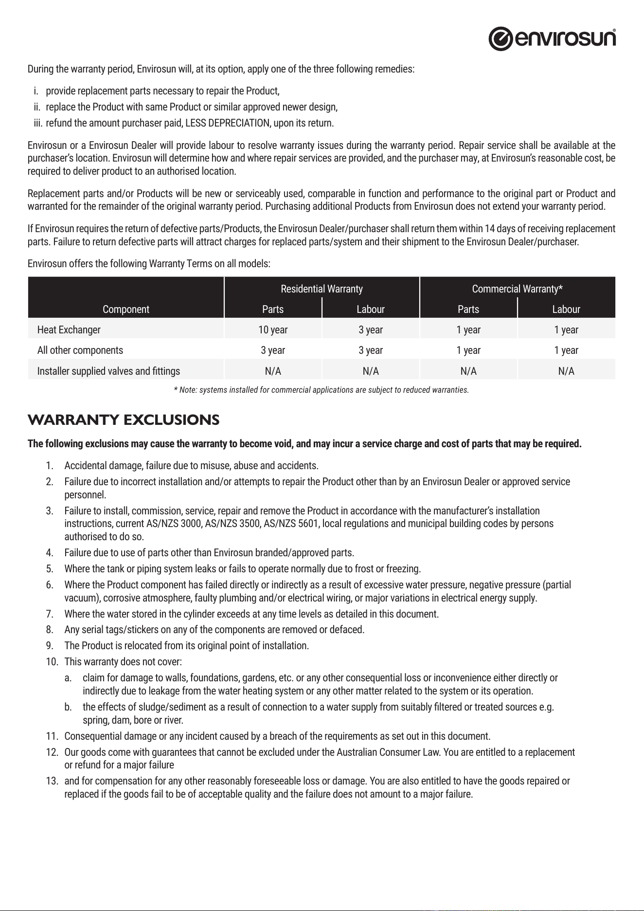
Envirosun offers the following Warranty Terms on all models:
Component
Residential Warranty Commercial Warranty*
Parts Labour Parts Labour
Heat Exchanger 10 year 3 year 1 year 1 year
All other components 3 year 3 year 1 year 1 year
Installer supplied valves and ttings N/A N/A N/A N/A
* Note: systems installed for commercial applications are subject to reduced warranties.
WARRANTY EXCLUSIONS
The following exclusions may cause the warranty to become void, and may incur a service charge and cost of parts that may be required.
1. Accidental damage, failure due to misuse, abuse and accidents.
2. Failure due to incorrect installation and/or attempts to repair the Product other than by an Envirosun Dealer or approved service
personnel.
3. Failure to install, commission, service, repair and remove the Product in accordance with the manufacturer’s installation
instructions, current AS/NZS 3000, AS/NZS 3500, AS/NZS 5601, local regulations and municipal building codes by persons
authorised to do so.
4. Failure due to use of parts other than Envirosun branded/approved parts.
5. Where the tank or piping system leaks or fails to operate normally due to frost or freezing.
6. Where the Product component has failed directly or indirectly as a result of excessive water pressure, negative pressure (partial
vacuum), corrosive atmosphere, faulty plumbing and/or electrical wiring, or major variations in electrical energy supply.
7. Where the water stored in the cylinder exceeds at any time levels as detailed in this document.
8. Any serial tags/stickers on any of the components are removed or defaced.
9. The Product is relocated from its original point of installation.
10. This warranty does not cover:
a. claim for damage to walls, foundations, gardens, etc. or any other consequential loss or inconvenience either directly or
indirectly due to leakage from the water heating system or any other matter related to the system or its operation.
b. the effects of sludge/sediment as a result of connection to a water supply from suitably ltered or treated sources e.g.
spring, dam, bore or river.
11. Consequential damage or any incident caused by a breach of the requirements as set out in this document.
12. Our goods come with guarantees that cannot be excluded under the Australian Consumer Law. You are entitled to a replacement
or refund for a major failure
13. and for compensation for any other reasonably foreseeable loss or damage. You are also entitled to have the goods repaired or
replaced if the goods fail to be of acceptable quality and the failure does not amount to a major failure.
manual_2025_A20-A26_HPW3.indd 13manual_2025_A20-A26_HPW3.indd 13 18/03/2025 12:40:40 PM18/03/2025 12:40:40 PM

Page 14 of 14
ver 250318.12
OH&S DISCLAIMER
Envirosun and its Authorised Dealers work with and recommend various installation and plumbing companies to install, test and certify correct
operation of solar hot water systems or the Product. Envirosun is a supplier of systems only.
Each installation must be covered by the installer’s insurances, commercial terms and conditions and by the applicable OH&S legislation. Each person
that installs assembles or services must comply with all OH&S requirements relevant to the type of work being conducted including, but not limited
to, plumbing work, work on heights exceeding 2.5m and electrical work.
The customer must ensure that it complies with all its OH&S obligations. This warranty will be void if these conditions are not met.
CONTACT DETAILS
For further information, please call one of the following phone numbers from anywhere in Australia:
Energie Group Australia Pty Ltd For after sales service: 1300 825 143
For sales or new product: 1300 314 173
www.energiegroup.au
Head Ofce Energie Group Australia Pty Ltd
460 Victoria Road, Malaga WA 6090
manual_2025_A20-A26_HPW3.indd 14manual_2025_A20-A26_HPW3.indd 14 18/03/2025 12:40:40 PM18/03/2025 12:40:40 PM