ERA 700 Performance IP
User Manual
with Safety and Installation Manual

Notes
Revision F
Rev. F of the ERA 700 Performance IP user documentation covers firmware version 1.1.2.
The Safety and Installation Manual includes instructions for using the M12 Mounting Blocks Kit accessory
in permanent outdoor installations. The User Manual includes instructions for replacing gobos and adds
items to the Information menu in the fixture’s control panel.
©2023-2025 HARMAN PROFESSIONAL DENMARK ApS. All rights reserved. Features, specifications and appearance are subject
to change without notice. HARMAN PROFESSIONAL DENMARK ApS and all affiliated companies disclaim liability for any injury,
damage, direct or indirect loss, consequential or economic loss or any other loss occasioned by the use of, inability to use or
reliance on the information contained in this document. Martin is a registered trademark of HARMAN PROFESSIONAL DENMARK
ApS registered in the United States and/or other countries.
HARMAN PROFESSIONAL DENMARK ApS, Olof Palmes Allé 44, 8200 Aarhus N, Denmark
HARMAN PROFESSIONAL, INC., 8500 Balboa Blvd., Northridge CA 91325, USA
www.martin.com
ERA 700 Performance IP User Manual with Safety and Installation Manual, English, Revision F, P/N 1000378123

Table of contents
Introduction ........................................................................................................... 5
Features .......................................................................................................... 5
Before using the product for the first time ....................................................... 5
Connecting to data ............................................................................................... 6
Data via DMX cable ........................................................................................ 6
Data via Ethernet cable ................................................................................... 7
Effects .................................................................................................................. 8
Rotating gobos ................................................................................................ 9
Non-rotating gobos ........................................................................................ 10
Animation wheel ............................................................................................ 11
Light and heavy frost ..................................................................................... 11
Prisms ........................................................................................................... 11
Iris .................................................................................................................. 11
Zoom ............................................................................................................. 11
Framing ......................................................................................................... 11
Pan and Tilt ................................................................................................... 12
Fixture setup using the control panel ................................................................. 13
Using the control menus ............................................................................... 13
Display sleep ................................................................................................. 14
Disabling the control panel ............................................................................ 14
DMX mode setting ......................................................................................... 14
DMX address setting ..................................................................................... 14
Network settings ............................................................................................ 15
Pan/tilt inversion ............................................................................................ 15
Pan/tilt speed ................................................................................................ 15
Pan and tilt limits ........................................................................................... 15
Dimming curves ............................................................................................ 16
Dimming speed and smoothness .................................................................. 16
Blackout or Hold if DMX signal stops ............................................................ 16
Scene capture ............................................................................................... 16
Cooling mode ................................................................................................ 17
Focus tracking ............................................................................................... 17
Outdoor protection settings ........................................................................... 17
Display rotation ............................................................................................. 18
Display intensity ............................................................................................ 18
Temperature units ......................................................................................... 19
Resetting to factory defaults ......................................................................... 19
Fixture test .................................................................................................... 19
Fixture information ........................................................................................ 20
DMX Live ....................................................................................................... 21
Resetting the fixture ...................................................................................... 21
Manual control ............................................................................................... 21
Disabling pan and tilt feedback ..................................................................... 21
Calibration settings ........................................................................................ 21
Control/Settings via DMX ................................................................................... 23
Parameter shortcuts ...................................................................................... 23
Blacking out the display ................................................................................ 23
Hibernation mode .......................................................................................... 23

Tungsten emulation ....................................................................................... 23
Calibrating effects via DMX ........................................................................... 23
Using RDM ......................................................................................................... 25
Martin Companion
®
and RDM ....................................................................... 25
Fixture discovery ........................................................................................... 25
Supported parameters .................................................................................. 25
Example: setting a DMX address .................................................................. 26
Fixture information ......................................................................................... 26
Status messages ........................................................................................... 26
Managing the fixture ...................................................................................... 26
RDM functions ............................................................................................... 27
Operating the fixture ........................................................................................... 30
Controlling via DMX ....................................................................................... 30
Control menus .................................................................................................... 31
DMX protocols .................................................................................................... 36
Basic DMX Mode ........................................................................................... 36
Extended DMX Mode .................................................................................... 41
Control/Settings DMX channel ........................................................................... 46
Replacing gobos ................................................................................................. 48
Avoiding damage to gobos ............................................................................ 48
Opening the head for access ........................................................................ 49
Gobo replacement procedure ....................................................................... 49
Installing a gobo in a goboholder .................................................................. 51
Gobo orientation guide ....................................................................................... 52
Vacuum testing after opening the fixture ............................................................ 53
Pan/tilt and zoom orientation guide .................................................................... 54

Martin
®
ERA 700 Performance IP User Manual Rev. F 5
Introduction
Warning! Before installing, operating or servicing the ERA 700 Performance IP
lighting fixture, read the latest version of the fixture’s Safety and Installation
Manual, paying particular attention to the Safety Precautions section. The
Safety and Installation Manual is supplied with the fixture and included at the
back of this user manual.
Important! Full specifications for ERA 700 Performance IP fixtures and
accessories are available in the ERA 700 Performance IP area of the Martin®
website at www.martin.com.
Thank you for selecting the ERA 700 Performance IP lighting fixture from Martin.
This User Guide is a supplement to the Safety and Installation Manual that is supplied with the fixture
and attached to the back of this User Manual. This combined User Manual plus Safety and Installation
Manual is available for download from the ERA 700 Performance IP area of the Martin website at
www.martin.com. The User Manual contains information that is mainly of interest for lighting designers
and operators, whereas the Safety and Installation Manual contains important information for all users,
especially installers and technicians.
We recommend that you check the Martin website regularly for updated documentation. We publish
revised versions each time we can improve the quality of the information we provide and each time we
release new firmware with changes or new features. Each time we revise this guide we list any
important changes on page 2 so that you can keep track of updates.
Features
All ERA 700 Performance IP fixtures feature:
• Long-life, high output LED engine
• DMX and network control
• RDM configuration and addressing
• IP66 ingress protection rating when the supplied anti-tamper box is installed (the fixture is suitable
for permanent or temporary outdoor or indoor use for entertainment purposes)
• Integrated 100-240 V~, 50/60 Hz auto-ranging power supply.
Before using the product for the first time
1. Check the ERA 700 Performance IP area of the Martin website at www.martin.com for the most
recent user documentation and technical information about the fixture. Martin user manual
revisions are identified by the revision letter at the bottom of the inside cover. Read the latest
revision of the ERA 700 Performance IP Safety and Installation Manual that is included at the end
of the User Manual, paying particular attention to the ‘Safety Precautions’ section.
2. Unpack and ensure that there is no transportation damage before using the fixture. Do not attempt
to operate a damaged fixture.
3. Before operating, ensure that the voltage and frequency of the power supply match the power
requirements of the fixture.
4. If fixtures are exposed to a sudden temperature change, give them time to warm or cool to the
ambient temperature before applying power. This will help avoid damage due to condensation.

6 Martin
®
ERA 700 Performance IP User Manual Rev. F
Connecting to data
Warning! Before installing the ERA 700 Performance IP, read the latest version of the fixture’s Safety
and Installation Manual that is attached to the User Manual, paying particular attention to the ‘Safety
Precautions’ section. Besides important safety information, the Safety and Installation Manual contains
instructions for connecting to AC mains power.
When using the fixture outdoors or in any environment where water or humidity is present, use IP65-
rated connectors and keep the anti-tamper box installed over the connections panel with the cable
openings facing downwards.
If independent control of a fixture is required, it must have its own DMX channels. Fixtures that are
required to behave identically can share the same DMX address and channels.
The number of fixtures that you can connect to DMX data in a daisy chain is limited by the number of
DMX channels required by the fixtures. A maximum of 512 channels is available in one DMX universe.
To add more fixtures or groups of fixtures when you no longer have enough DMX channels, add a
DMX universe and another daisy-chained link.
The ERA 700 Performance IP has two pairs of connectors for control data In/Out:
• one pair of locking 5-pin XLR sockets that accept IP65-rated Neutrik TOP (or compatible)
connectors, and
• one pair of etherCON sockets that accept IP65-rated Neutrik TOP (or compatible) Ethernet
connectors.
All sockets are protected by rubber caps. Keep the rubber caps in place at all times on unused sockets.
Data via DMX cable
The ERA 700 Performance IP has 5-pin locking XLR sockets for DMX and RDM input and output via
DMX cable. The pin-out on both sockets is:
• Pin 1 to shield
• Pin 2 to data 1 cold (-)
• Pin 3 to data 1 hot (+).
Pins 4 and 5 are not used by the fixture but are bridged between input and output sockets. These pins
can therefore be used as a pass-through connection for an additional data signal if required.
Tips for reliable data transmission via DMX cable
• Use shielded twisted-pair high-quality DMX cable.
• 24 AWG cable is suitable for runs up to 300 meters (1000 ft). Heavier gauge cable and/or an
amplifier is recommended for longer runs.
• Do not use microphone cable, as standard microphone cable does not have the correct impedance
and cannot transmit control data reliably over long runs.
• To split the data link into branches, use an optically isolated splitter-amplifier. Use an RDM-
compatible splitter-amplifier if using RDM.
• Do not overload the DMX data link. You can connect up to a maximum of 32 devices on a serial
DMX link.
• Install a DMX termination plug at the end of the DMX link.
Connecting to data via DMX cable
To connect the fixture to DMX and/or RDM data carried over DMX cable:
1. Connect the DMX data output from the controller to the fixture’s data input (male XLR) socket
using good-quality DMX cable.
2. Run DMX cable from the fixture’s data output (female XLR) socket to the data input of the next
fixture and continue until the link is complete.

Martin
®
ERA 700 Performance IP User Manual Rev. F 7
3. Terminate the data link by connecting a 120 Ohm, 0.25 Watt resistor between the data 1 hot (+)
and cold (-) conductors at the end of the link. If the link is divided into branches using a DMX
splitter, terminate each branch of the link.
Data via Ethernet cable
The ERA 700 Performance IP has etherCON data sockets that support DMX and RDM over Art-Net
and sACN. Either socket can be used for input and the other socket used for throughput. The
etherCON data sockets have a fail-safe bypass feature. This means that the fixture will relay a data
signal from the socket used for input to the socket used for throughput even if power to the fixture is
shut down or lost.
Tips for reliable data transmission via Ethernet cable
• Use shielded twisted-pair Ethernet cable of type S/UTP, SF/UTP, S/STP or SF/STP only. The cable
must be rated Cat 5e or better.
• The cable shield must be electrically connected to connector housings, and the other devices on the
data link must also support shielded connections.
• The ERA 700 Performance IP is compatible with 10/100 Mbit Ethernet only. Do not connect the
fixture to a network port or device that is fixed to Gigabit Ethernet speed. If you need to integrate an
ERA 700 Performance IP in a Gigabit Ethernet network, use a network switch to allow the link
towards the fixture to operate at 100 Mbit/s Ethernet speed.
• To split the data link into branches, use a standard network switch that is able to operate at 100
Mbit/s towards the fixtures.
• Even though every fixture has a fail-safe bypass mechanism and minimal latency insertion, we
recommend that you avoid connecting more than 50 devices in a single daisy-chain or branch.
• Unlike DMX cable, Ethernet cable does not require termination at the end of a daisy-chain of
fixtures.
Connecting to data via Ethernet cable
To connect the fixture to Art-Net or sACN via Ethernet cable:
1. Connect the Ethernet cable to either of the fixture’s etherCON data sockets.
2. Run Ethernet cable from the fixture’s other etherCON data socket to a data socket on the next
fixture.
3. Continue connecting data sockets as described above until the link is complete.
8 Martin
®
ERA 700 Performance IP User Manual Rev. F
Effects
See the ‘DMX protocols’ section starting on page 36 for a full list of the DMX channels and values
required to control the different effects.
Shutter
The electronic ‘shutter’ effect provides instant open and blackout, variable speed regular and random
strobe.
Dimmer
Overall intensity can be adjusted 0-100% using smooth continuous electronic dimming with 16-bit
control resolution.
CMY color mixing
The fixture features CMY color mixing with 16-bit resolution. Colors are obtained using continuously
variable dichroic color flags.
You may find it advantageous to deploy the CRI filter on the color wheel (see below) in combination
with CMY color mixing.
Color temperature
The CTO channel lets you progressively reduce the color temperature of the fixture’s white point from
the default 6500 K to 2700 K by deploying a variable dichroic CTO filter.
Color wheel
See illustration on right. The
fixture features a color wheel
with seven dichroic color
filters plus open. Besides
continuous scrolling and
stepped (full colors) scrolling,
the color wheel also offers
continuous scrolling with
variable speed and direction
and random colors.
You can use CMY color
mixing in combination with
the color wheel if you want to
fine-tune a color.
You may find it
advantageous to deploy the
Spectral Enhancement filter
in combination with CMY
color mixing.
1
Red 627
2
Deep
Blue 498
3
Deep Green
500-544
4
Lavender
421
5
Deep
Orange 581
6
Spectral
Enhancement
7
Congo Blue
181
Martin
®
ERA 700 Performance IP User Manual Rev. F 9
Rotating gobos
The rotating gobo wheel in the ERA 700 Performance IP has
seven (7) rotating gobos that can be selected, indexed
(positioned at an angle), rotated continuously, and shaken
(bounced). The entire rotating gobo wheel can also be scrolled
continuously or shaken.
Gobo selection and control type (indexing, continuous gobo
rotation, gobo shake or continuous gobo wheel scrolling) are
selected on channel 13 in both Basic and Extended DMX
modes. Depending on what is selected on this channel, the
gobo indexed angle or gobo rotation speed are set on channels
14 and 15 with 16-bit control.
The slots on the rotating gobo wheel are ordered as shown on
the right. The fixture’s standard gobos are shown in the correct
order below.
1
2
3
4
5
6
7
Slot
Gobo
1
Tri Array
2
Ker Pow
3
Mirror Block
4
Stretched Out
5
Point and Curve
6
Pandora’s Cluster
7
Limbo (fused glass)
1
2
3
4
5
6
7
Rotating gobo wheel (seen from
LED side)
ERA 700 Performance IP rotating gobos
10 Martin
®
ERA 700 Performance IP User Manual Rev. F
Non-rotating gobos
The fixture’s static gobo wheel has eight (8) non-rotating gobos.
The gobo wheel can be indexed in steps, which inserts full
gobos only into the beam, it can be indexed continuously giving
the possibility of split gobos, or it can be shaken with the shake
centered on the gobo you select.
The slots on the static gobo wheel are ordered as shown on the
right. The fixture’s standard non-rotating gobos are shown in the
correct order below.
Non-rotating gobo selection, gobo wheel continuous scrolling,
gobo shake and random gobo selection are selected on channel
16 in both Basic and Extended DMX modes.
1
2
3
4
5
6
7
8
Slot
Gobo
1
Window Perspective
2
Dots and Dashes
3
Wurly Curly
4
Lava Shimmer
5
Wool Ball
6
Pave the Way
7
Square Perspective
8
Paint Play
Static gobo wheel (seen from
LED side)
1
2
8
4
6
7
5
3
ERA 700 Performance IP non-rotating gobos
Martin
®
ERA 700 Performance IP User Manual Rev. F 11
Animation wheel
The ERA 700 Performance IP is supplied with the
“Happy Daze” gobo animation wheel (P/N 5144517-00)
installed. The wheel can be used to add animation
effects to gobo projections. When using gobo
animation, adjusting the fixture’s focus will help obtain
the most realistic results.
You can insert the animation wheel into the beam or
select a gentle animation wheel shake (a gentle
rocking movement) with variable speed on channel 17
in Basic and Extended DMX Modes. Once you have
deployed the animation wheel on channel 17, you can
select a static indexed angle, continuous animation
wheel rotation or define the center angle for the
animation wheel gentle shake with 8-bit resolution on
channel 18 in Basic DMX Mode or with 16-bit
resolution on channels 18 and 19 in Extended DMX
Mode.
Light and heavy frost
The ERA 700 Performance IP features two frost filters that are controllable via DMX: a light and a
heavy filter. One or both filters can be inserted into the beam at any one time.
Prisms
The ERA 700 Performance IP features two prisms that are controllable via DMX:
• Prism 1 is a four-facet circular prism.
• Prism 2 is a six-facet linear prism
You can insert one prism into the beam at any one time. Once you have selected a prism, you can
shake it, set it to an indexed angle or set it to continuous rotation with variable direction and speed.
Iris
The fixture has a motorized iris that can be set to a static aperture to narrow the beam. You can also
set the iris to a dynamic opening or closing pulse with variable speed.
Zoom
Zoom control via DMX lets you vary the beam angle within this range:
• Wide
- Half-peak angle (50%): 41.1°
- Field angle (10%): 44.2°
- Cutoff angle (3%): 44.8°
• Narrow
- Half-peak angle (50%): 5.4°
- Field angle (10%): 7.1°
- Cutoff angle (3%): 7.9°
Framing
The 4-blade framing module in the ERA 700 Performance IP can be rotated to an indexed position
within a range of 120°. Independent control of angle and amount of insertion is available for each
‘Happy Daze’ gobo animation
wheel

12 Martin
®
ERA 700 Performance IP User Manual Rev. F
framing blade. You can insert one or more blades into the beam projection and also form the beam into
any shape with three or four flat sides.
Pan and Tilt
The ERA 700 Performance IP ’s head can pan through a range of 540° and tilt through 270° with 16-bit
control resolution in both Basic and Extended DMX Modes.
Martin
®
ERA 700 Performance IP User Manual Rev. F 13
Fixture setup using the control panel
This section explains how to adjust fixture settings using the menus available in the fixture’s control
panel. You can find details of additional functions that are not available in the control panel in the
chapters on the Control/Settings DMX channel and on setup via RDM later in this user manual.
Any changes that you make to the fixture’s settings are stored in memory when the fixture is powered
off.
You can find a complete map of the control menu structure in ‘Control menus’ on page 31.
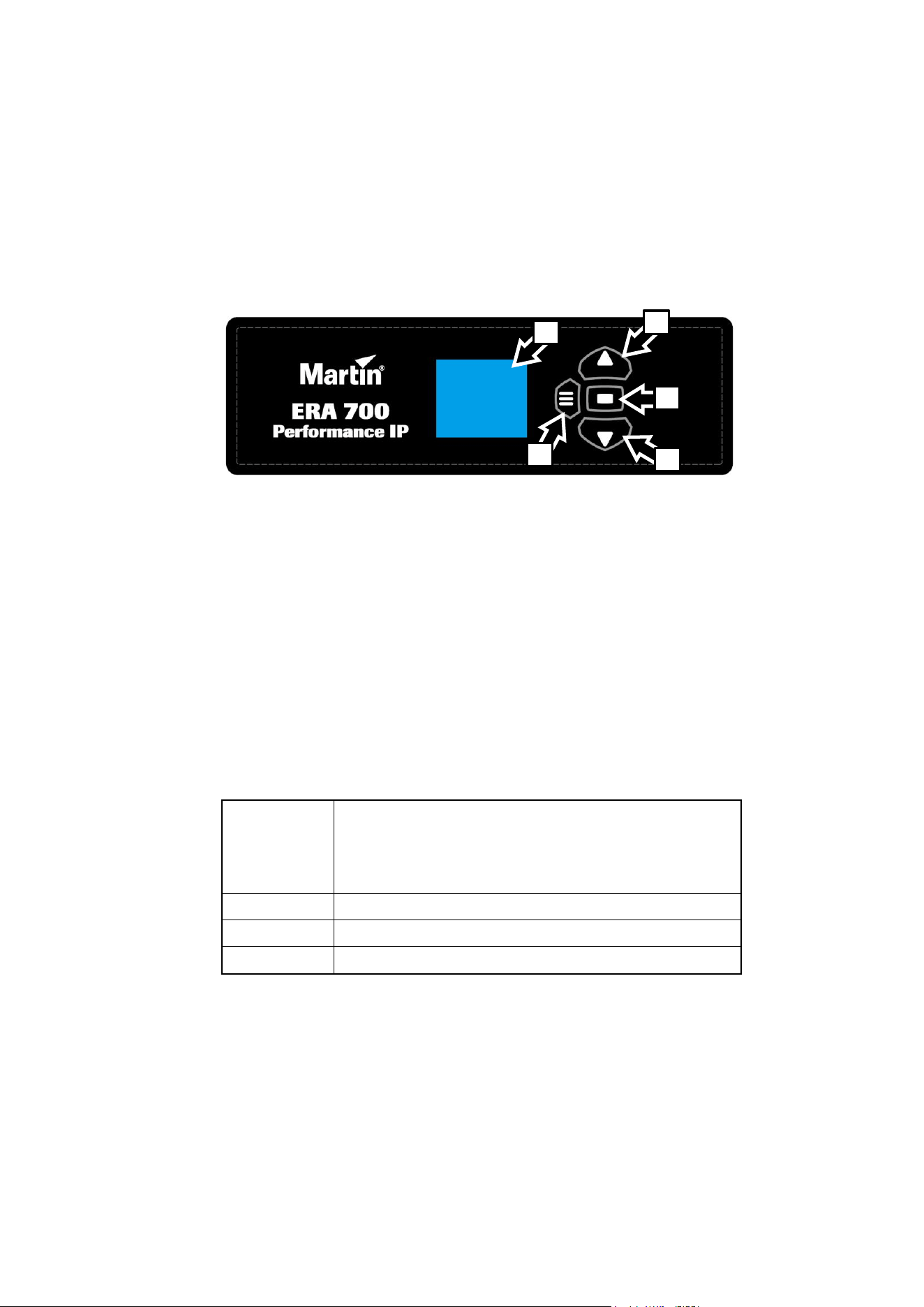
A – Control panel display
B – Menu button
C – Down button
D – Up button
E – Enter button
Using the control menus
The control panel buttons are touch-sensitive. The control panel flashes briefly to confirm when a
keypress has been registered. The buttons have the following functions:
MENU
• Activate the control menus, or
• open the Shortcuts menu by holding for 2 seconds, or
• return to the previous level of the menu structure, or
• press to exit the menus
DOWN
Scroll down a menu
UP
Scroll up a menu
ENTER
Confirm the selected function
Special keypress functions
• Pressing the UP and DOWN buttons together rotates the control panel display through 180°.
• Pressing the MENU and UP buttons together resets the entire fixture.
• Pressing and holding the MENU button for two seconds opens a Shortcuts menu (see next page).
• Holding the MENU button pressed while applying power puts the fixture into Service Mode. Pan
and tilt are disabled in order to avoid head movement causing problems during service operations
with the fixture powered on.
Cycling power and allowing the fixture to start up normally takes it out of Service Mode.
D
E
C
B
A

14 Martin
®
ERA 700 Performance IP User Manual Rev. F
Shortcuts menu
Pressing and holding the MENU button for two seconds opens a small Shortcuts menu with three
items:
• RESET ALL carries out a complete reset of the fixture with all its effects.
• ROTATE DISPLAY rotates the control panel display through 180°. This function makes it easier to
read the control panel menus when changing from standing to hanging installation.
• PERSONALITY VIEW displays a list of the fixture’s personality settings. Use the DOWN and UP
buttons to scroll through the list.
Display sleep
The control panel display blacks out automatically after two minutes with no key press. As soon as a
button on the control panel is pressed, or if the fixture’s self-diagnosis system detects an error, the
display lights up again. If an error has been detected, the display will show a red exclamation mark !
Pressing ENTER displays a short error message to identify the error.
Disabling the control panel
To avoid tampering or accidental triggering, it is possible to lock the control panel buttons using the
PERSONALITY → DISPLAY → SCREEN LOCK menu. As soon as you set SCREEN LOCK to ON, the
buttons on the control panel are disabled and the display shows the main menu.
To re-enable use of the control panel buttons and display temporarily, press the UP-DOWN-UP-
DOWN-ENTER buttons in sequence. The control buttons and display will remain enabled until the
display blacks out two minutes after the last keypress. At this point, the lock function will be reapplied
and the control panel buttons will be disabled again.
To disable the lock function and return to normal use of the control panel, release the lock temporarily
with the UP-DOWN-UP-DOWN-ENTER sequence, then open the PERSONALITY → DISPLAY →
SCREEN LOCK menu and set it to OFF.
DMX mode setting
The ERA 700 Performance IP offers two DMX modes: Basic and Extended. See the ‘DMX protocols’
section at the end of this manual for details of the DMX control options available in the different modes
and the number of DMX channels used.
Because the fixture’s DMX mode affects the number of DMX channels used, it will also affect the
assignment of DMX addresses to fixtures. It can therefore be a good idea to set the DMX mode of all
the fixtures in the installation before you set their DMX addresses.
DMX address setting
The DMX address, also known as the start channel, is the first channel used to receive instructions
from a DMX controller. If you have a group of fixtures and you set the first fixture’s DMX address to 1,
the fixture will use DMX channel 1 and the channels above it (the number of channels used will depend
on the fixture’s DMX mode). The channels above these are available for the next fixture.
For independent control, each fixture must be assigned its own control channels. You can give the
same DMX address to two fixtures of the same type if you want them to behave identically. Giving the
same DMX address to multiple fixtures can be useful for grouped control and troubleshooting.
To set the fixture’s DMX address:
1. On the fixture’s control panel, press MENU to activate the menus. In the DMX SETUP menu,
select DMX ADDRESS and press ENTER. The fixture’s currently set DMX address will blink in the
display.
2. Use the UP and DOWN buttons to select a new address.
3. Once the new address has been selected, press ENTER to confirm it (or press MENU to exit
without making a change).

Martin
®
ERA 700 Performance IP User Manual Rev. F 15
Network settings
The PERSONALITY → NET ADDRESS menu lets you manually set the fixture’s DMX universe, IP
address and subnet mask.
PERSONALITY → NET SWITCH lets you set the fixture to automatically detect and respond to any
compatible data signal protocol (sACN or Art-Net) received at one of its Ethernet ports. This function is
enabled by default.
Pan/tilt inversion
The PERSONALITY → PAN INVERSE and TILT INVERSE menus let you reverse the direction of pan
and tilt. This can be useful if you want to create symmetrical effects with multiple fixtures, or if you want
to coordinate the movement of fixtures that are standing on the floor with fixtures that are being flown
upside down in a rig.
To adjust the pan inversion settings:
1. Select PAN INVERSE and press ENTER to confirm. The currently set mode will blink in the
display.
2. Use the DOWN and UP buttons to select YES (pan inversion) or NO (normal) mode.
3. Press ENTER to save your selection.
You can adjust the tilt inversion settings in the same way in the TILT INVERSE menu.
Pan/tilt speed
The PAN / TILT SPEED command lets you choose between three settings:
• STANDARD is designed to give a good compromise between speed and smoothness of pan and
tilt movement.
• FAST optimizes pan and tilt movement for speed. Slow pan and tilt movement may be less
smooth.
• SMOOTH optimizes pan and tilt movement for smoothness. Maximum pan and tilt movement
speed is reduced.
Pan and tilt limits
The pan and tilt limit options let you define minimum and maximum limits for pan and tilt angles so that
you can install fixtures close to obstacles (such as other fixtures or trusses) with no risk of collision, so
that the beam will only hit a certain area of a stage or set, or so that you can avoid the fixture shining
into the eyes of the audience, for example. If you set limits, the fixture’s pan and tilt movement will
remain in a ‘safe zone’ within those limits.
Store lower pan limit and Store upper pan limit set minimum and maximum limits for the fixture’s
pan range. Store lower tilt limit and Store upper tilt limit do the same thing for tilt range.
To set a limit, use the pan or tilt DMX channel to move the head to the position where you want to set
the limit, then send the appropriate Store command on the Control/Settings DMX channel. You must
send the Store command for at least 1 second to activate it.
Once you have stored one or more pan and tilt limits, send an Enable pan and tilt limits command to
activate the limits. Sending a Reset pan/tilt limits command erases all the limits that have been
stored.
A LIM message appears in the control panel display when one or more pan and tilt limits are active.
Note that when you power the fixture off, the head may move under its own weight to a position that is
outside its pan and tilt limits.
16 Martin
®
ERA 700 Performance IP User Manual Rev. F
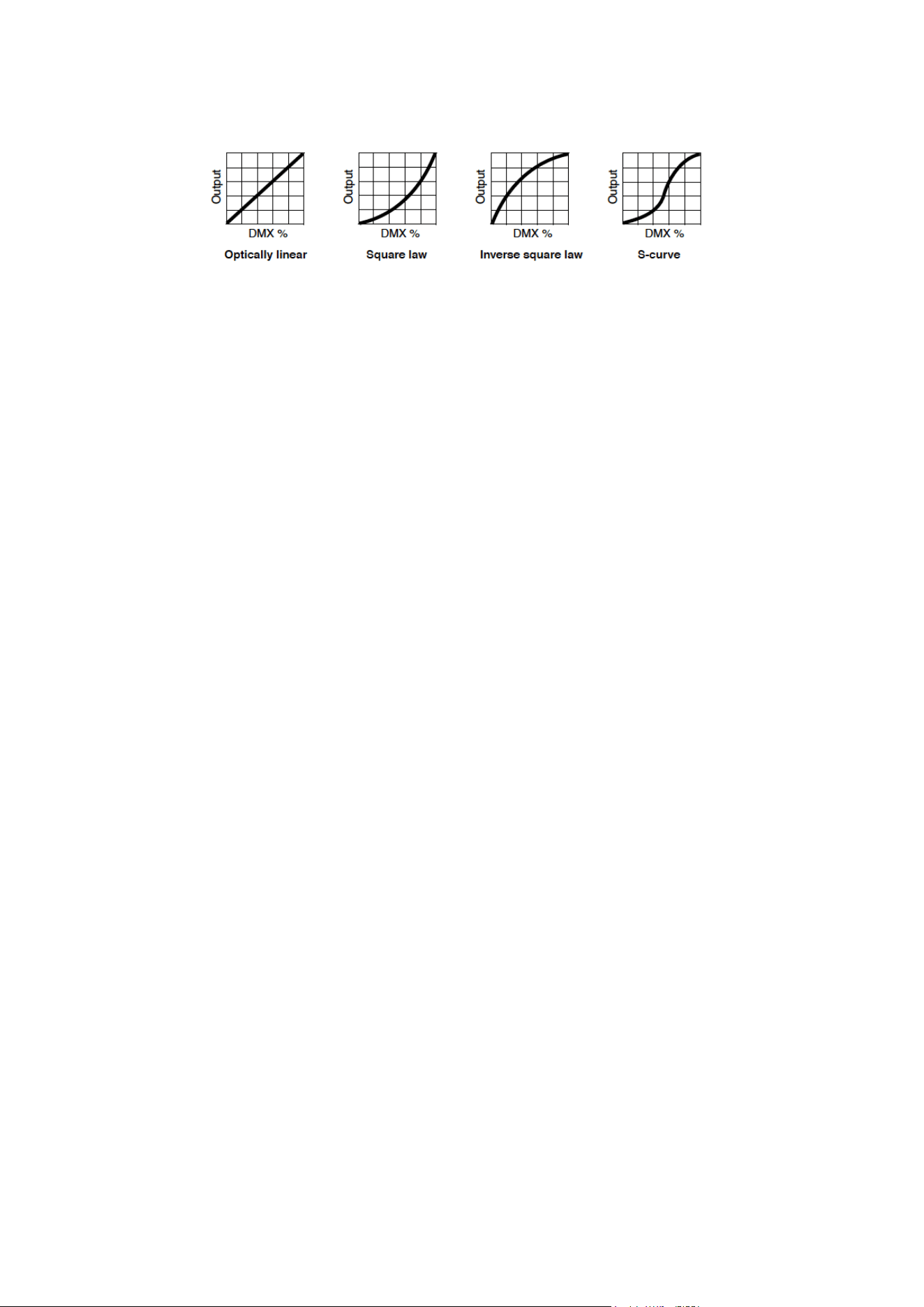
Dimming curves
Four dimming curves are available:
• LINEAR – The increase in light intensity appears to be linear as DMX value is increased.
• SQUARE LAW – light intensity control is finer at low levels and coarser at high levels.
• INVERSE SQUARE LAW – light intensity control is coarser at low levels and finer at high levels.
• S-CURVE – light intensity control is finer at low levels and high levels and coarser at medium
levels.
To set the fixture’s dimming curve:
1. Select DIMMER CURVE and press ENTER. The currently set dimming curve mode will blink in the
display.
2. Use the DOWN and UP buttons to select LINEAR, SQUARE LAW, INV SQ LAW, or S-CURVE.
3. Press ENTER to confirm your choice (or press MENU to exit without making a change).
Dimming speed and smoothness
You can optimize dimming to give either the fastest or the smoothest changes in dimming levels. To
optimize dimming:
1. Select DIMMING SPEED and press ENTER.
2. Use the DOWN and UP buttons to select FAST (dimmer optimized for speed) or SLOW (dimmer
optimized for smoothness).
3. Press ENTER to confirm your choice (or press MENU to exit without making a change).
Blackout or Hold if DMX signal stops
You can decide how the fixture should behave if you are controlling the fixture via DMX and then you
stop sending the DMX data signal:
1. Select NO DATA MODE and press ENTER. The currently set mode will blink in the display.
2. Using the DOWN and UP buttons, select BLACKOUT or HOLD to decide how the fixture should
respond if it stops receiving a DMX signal:
- If you select BLACKOUT, the fixture will black out
- If you select HOLD, the fixture will continue to show the effect that it is displaying at the time.
3. Press ENTER to confirm your choice (or press MENU to exit without making a change).
Scene capture
The SCENE CATCH menu lets you capture all the DMX values that the fixture is currently receiving
and save them as a ‘standalone scene’ that you can choose to play back each time that fixture power
is cycled off and on or each time that you carry out a reset.
Three scene capture controls are available:
• SCENE CATCH RECORD stores the currently displayed scene in the fixture’s memory. Once you
have captured a scene, the fixture keeps that scene in memory even if you cycle power off and on
again.
• SCENE CATCH → ON sets the fixture to show the scene that is stored in memory if the fixture is
powered on but is not receiving a DMX signal.

Martin
®
ERA 700 Performance IP User Manual Rev. F 17
If the fixture receives a DMX control signal during scene playback, it will immediately stop showing
its saved scene. If fixture power is cycled off and on again or if the fixture is reset, it will again show
its saved scene.
• SCENE CATCH → OFF disables the scene playback function: the fixture does not show the scene
that is stored in memory if it stops receiving a DMX signal.
Setting SCENE CATCH to OFF does not delete the saved scene from memory: the scene will still
be available if you set SCENE CATCH to ON again.
Cooling mode
The cooling mode setting lets you decide whether to give priority to lowest cooling fan noise or
maximum light output:
1. Select COOLING MODE and press ENTER. The currently set cooling mode will blink in the
display.
2. Using the DOWN and UP buttons, select one of the cooling options:
- The REGULATED FANS setting adjusts cooling fan operation to balance the fixture’s noise and
light output characteristics. Fans are set to the lowest speed possible and then increased as
fixture operating temperature rises. If the fixture reaches maximum operating temperature and
full-speed fan operation is not enough to control fixture temperature, light output intensity is
limited to keep the fixture within its operating temperature range.
- At the FULL setting, the fans operate at constant full speed without temperature regulation.
This setting maximizes cooling and gives priority to the highest possible light output intensity.
FULL fan mode can also be used as a quick way of dislodging dirt from fans. The fixture
reduces light output if full fan speed is not enough to keep the fixture within its operating
temperature limits.
- At the MEDIUM setting, the fans operate at constant medium speed without temperature
regulation. The fixture reduces light output if medium fan speed is not enough to keep the
fixture within its operating temperature limits.
- At the LOW setting, the fans operate at constant low speed without temperature regulation.
The fixture reduces light output if low fan speed is not enough to keep the fixture within its
operating temperature limits.
- At the ULTRA LOW setting, the fans operate at constant very low speed without temperature
regulation in order to give the lowest possible noise level. The fixture reduces light output if
ultra-low fan speed is not enough to keep the fixture within its operating temperature limits.
3. Press ENTER to confirm your choice (or press MENU to exit without making a change).
Focus tracking
Focus tracking sets focus to automatically adjust to match the fixture’s zoom angle. You can enable or
disable focus tracking, and you can optimize this feature to give the sharpest focus at far, medium or
near projection distances. Focus tracking is enabled and set to ‘Medium distance’ by default.
Regardless of whether focus tracking is enabled or disabled, you can always adjust focus via DMX.
Outdoor protection settings
The fixture offers the functions described below to help it deal with outdoor conditions.
Sunlight protection
The fixture’s automatic SUNLIGHT PROTECTION function closes two framing blades automatically
when the fixture has been dimmed to blackout for more than 60 seconds, giving some degree of
protection from sunlight damage to the fixture internals. As soon as the dimmer is opened, the framing
blades open again.
We recommend that you dim the fixture to zero at the end of every show, and then allow 60 seconds
for the framing blades to close. This will give some degree of protection if fixtures are removed from
their flightcases and standing in sunlight for a short period while waiting to be installed, for example.

18 Martin
®
ERA 700 Performance IP User Manual Rev. F
We still strongly recommend that fixtures are kept with the front of the head pointing away from the sun
and other powerful light sources at all times.
Note that the opening of the framing blades is visible for a fraction of a second when the dimmer is
opened. If you prefer to avoid this in a show where the fixture is blacked out for more than 60 seconds,
disable SUNLIGHT PROTECTION.
SUNLIGHT PROTECTION is disabled by default.
Standby heating
The fixture’s bearings, other moving parts and lubricants may fail to operate correctly and may suffer
damage if the fixture is used when they are too cold. The CLIMATE CONTROL → STANDBY
HEATING function gives you options to protect the fixture and ensure good performance when the
ambient temperature falls below freezing point.
• When set to ON (the default setting), the fixture maintains a constant low-level heating when the
ambient temperature falls below freezing point. This means that the fixture can start up immediately
after a period when it has not been in use and the temperature has been below freezing.
• When set to OFF, the fixture first goes into a warm-up sequence to warm up grease and bearings
when it is powered on after a period when it has not been in use and the ambient temperature has
been below freezing point. Mechanical effects are disabled until the fixture has warmed up to within
its operating temperature range. The warm-up time required will typically be 20 minutes at -20° C
(-4° F) and 40 minutes at -40° C (-40° F).
De-humidification
The fixture’s DE-HUMIDIFY function reduces internal humidity, reducing the risk of condensation
buildup inside the fixture. It is possible for a certain amount of condensation to be visible behind the
front lens of an IP66-rated lighting fixture in certain environmental conditions, and this is not normally a
problem. However, if condensation becomes visible we recommend that you run a forced de-
humidifying sequence (see below) as soon as possible.
• When set to ON (the default setting), the fixture automatically detects excess humidity while it is
operating and runs a de-humidifying sequence before normal operation is available. This feature
can be useful when the fixture is placed in a humid environment with long standby periods.
• When set to OFF, automatic de-humidifying functionality is disabled.
You can run the de-humidifying sequence manually at any time using the SERVICE → FORCE DE-
HUMDIFY command. Note that normal operation is paused during the de-humidifying sequence.
If the fixture’s DE-HUMIDIFY function begins to run constantly, there is probably a leak that is allowing
moisture to enter the fixture. Contact your Martin supplier for help.
Display rotation
To set the orientation of the control panel display:
1. Select DISPLAY → DISPLAY ROTATION and press ENTER.
2. Use the DOWN and UP buttons to select NORMAL (display in normal orientation) or ROTATE
180° (display inverted to make it easier to read if you install the fixture with the head hanging
vertically downwards).
3. Press ENTER to confirm your choice (or press MENU to exit without making a change).
Display intensity
To set the brightness of the control panel display:
1. Select DISPLAY → DISPLAY INTENSITY and press ENTER.
2. Use the DOWN and UP buttons to adjust the brightness of the display from 10% to 100%.
3. Press ENTER to confirm your choice (or press MENU to exit without making a change).

Martin
®
ERA 700 Performance IP User Manual Rev. F 19
Temperature units
To set the fixture to display temperatures in degrees Celsius or Fahrenheit:
1. Select DISPLAY → TEMPERATURE UNIT and press ENTER.
2. Use the DOWN and UP buttons to select °C or °F.
3. Press ENTER to confirm your choice (or press MENU to exit without making a change).
Resetting to factory defaults
To reset the fixture to its factory default settings:
1. In the DEFAULT SETTINGS menu, select FACTORY DEFAULT and press ENTER to confirm.
2. Use the DOWN and UP buttons to select YES to erase any custom settings that you have
configured and reset the fixture to its factory default settings, or select NO.
3. Press ENTER to confirm your choice (or press MENU to exit without making a change).
Note that this does not affect the fixture’s calibration settings.
Fixture test
You can run an automatic sequence to test all the fixture’s effects or manually test individual effects
using the control menus.
Automatic effects test
To perform a complete test of all of the fixture’s effects:
1. Select FIXTURE TEST → TEST ALL and press ENTER to confirm. The automatic test will run.
2. To stop the test and return to the previous level of the menu structure, press MENU.
Manual effects tests
You can also manually test individual effects.
To test LED dimming:
1. Select FIXTURE TEST → TEST DIMMER and press ENTER.
2. To stop the test and return to the previous level of the menu structure, press MENU.
To test an individual effect:
1. Select FIXTURE TEST → TEST EFFECTS and press ENTER.
2. Use the DOWN and UP buttons to scroll through all the fixture’s effects: CYAN, MAGENTA,
YELLOW, CTO, COLOR (color wheel), GOBO1 (rotating gobos on gobo wheel 1), RGOBO1
(rotation of the rotating gobos on gobo wheel 1), GOBO2 (static gobos on gobo wheel 2),
ANIMATION etc.
3. When you have reached the effect that you want to test, press ENTER to confirm your selection.
The fixture will now run an automatic test of that effect.
4. Press MENU to exit the test and return to the list of effects.
To manually test pan and tilt:
1. Select FIXTURE TEST → TEST PAN/TILT and then either PAN or TILT.
2. Press ENTER. The fixture will now run an automatic test of pan or tilt functionality.
3. To stop the test and return to the previous level of the menu structure, press MENU.

20 Martin
®
ERA 700 Performance IP User Manual Rev. F
Fixture information
Power on time
1. Select INFORMATION → POWER ON TIME and press ENTER to display the total number of
hours the fixture has been powered on since it left the factory.
2. To return to the previous level of the menu structure, press MENU.
LED operating time
1. Select INFORMATION → LED HOURS and press ENTER to display the total number of hours the
LEDs have been activated since the fixture left the factory.
2. To return to the previous level of the menu structure, press MENU.
Firmware version
To see which software version is installed in the fixture:
1. Select INFORMATION → SW VERSION and press ENTER. The display will indicate the currently
installed firmware version.
2. Use the UP and DOWN buttons to scroll through firmware revisions.
3. To return to the previous level of the menu structure, press MENU.
Fixture ID number
You can set a custom 4-digit ID number for the fixture to help you identify it. To manage the ID number:
1. Select INFORMATION → FIXTURE ID and press ENTER. The display will indicate the current
fixture ID number.
2. Use the DOWN and UP buttons to increase or decrease the current fixture ID number until you
reach the ID number that you want to allocate to the fixture.
3. Press ENTER to confirm the new ID number (or press MENU to exit without making a change).
RDM unique ID number
You can view the fixture’s unique non-resettable 12-digit RDM ID number. To view the RDM UID
number:
1. Select INFORMATION → RDM UID and press ENTER. The display will indicate the fixture’s
unique RDM ID number.
2. Press MENU to exit.
Serial number
To view the fixture’s factory serial number:
1. Select INFORMATION → SERIAL NUMBER and press ENTER.
2. Press MENU to exit.
Fixture temperature readouts
To check the onboard temperature of the fixture:
1. Select INFORMATION → TEMPERATURES and press ENTER. The fixture will display the current
temperatures of all the fixture’s PCBs.
2. To return to the previous level of the menu structure, press MENU.
Fixture type readout
To view the fixture’s type:
1. Select INFORMATION → FIXTURE TYPE and press ENTER.
2. To return to the previous level of the menu structure, press MENU.

Martin
®
ERA 700 Performance IP User Manual Rev. F 21
DMX Live
You can view the DMX values currently being received on each of the fixture’s DMX channels. This can
be useful for troubleshooting purposes.
To view the DMX values being received:
1. Select DMX LIVE and use the UP and DOWN buttons to scroll through the value being received on
each channel.
2. To return to the previous level of the menu structure, press MENU.
Resetting the fixture
You can reset the entire fixture to return it to its state when you powered it on, or you can reset its
effects only.
• To carry out a full reset, select MANUAL CONTROL → RESET → ALL, select YES or NO and
press ENTER. The entire fixture will reset as if you had cycled power. The full reset process will
take several seconds.
• To reset pan and tilt functionality only, you must first be prepared for the head to move through its
full pan and tilt ranges. Select MANUAL CONTROL → RESET → PAN/TILT and press ENTER.
The fixture will carry out a pan and tilt movement reset. The process will take several seconds.
• To reset only the fixture’s effects, select MANUAL CONTROL → RESET → EFFECTS and press
ENTER. All of the fixture’s effects will reset. The effects reset process will take several seconds.
Manual control
You can control all the fixture’s effects including pan and tilt manually without the need for a DMX
signal.
To manually control the fixture:
1. Select MANUAL CONTROL and then use the UP and DOWN buttons to scroll to the effect that you
want to control. Press ENTER.
2. Use the UP and DOWN buttons to scroll to the DMX value from 000 to 255 that you want to send
to that effect. Press ENTER to confirm and send that value.
3. To return to the list of effects, press MENU.
4. If you want to manually control other effects together with the first effect, repeat steps 1. and 2. and
3. above for the other effects.
The fixture will continue to show the effects that you have set manually until you set new manual
control values for the effects.
Exiting the MANUAL CONTROL menu by pressing the MENU button stops all the effects
immediately.
The effects are unaffected by a power OFF/ON cycle: if you power the fixture off and on again, it
will resume showing the effects.
When in manual control mode, pressing any button on the control panel lights up the control panel
display and shows the message MANUAL CONTROL MODE.
Disabling pan and tilt feedback
The fixture features pan/tilt position feedback sensors to ensure accurate positioning of the head.
Pan/tilt feedback is enabled by default. If you experience unexpected positioning behavior, it can be
useful to disable the feedback system by opening the SERVICE menu and selecting PAN/TILT
FEEDBACK → OFF.
Calibration settings
Martin fixtures are adjusted and calibrated at the factory, and further calibration should only be
necessary if fixtures have been subjected to abnormal shocks during transport or if normal wear and

22 Martin
®
ERA 700 Performance IP User Manual Rev. F
tear has affected alignment after an extended period of use. You can also use calibration to fine-tune
fixtures for a particular location or application.
The SERVICE → CALIBRATION menu lets you define values in the fixture software to adjust the
positions of pan, tilt and effects relative to the DMX values the fixture receives. Creating calibration
offsets like this allows you to fine-tune fixtures and achieve uniform behavior in multiple fixtures.
You can calibrate focus on each individual gobo (a feature that can be especially useful if you use
custom gobos). Calibrating focus at the open gobo position lets you adjust the fixture’s beam between
soft-edged and hard-edged when no gobo is being projected.
We recommend the following procedure to adjust the fixture’s calibration settings:
1. Aim a reference fixture and the fixtures that you want to calibrate at a flat surface. You can
calibrate fixtures one at a time or line up multiple fixtures in a row. Apply power and set pan, tilt and
effects to the same DMX values.
2. In each fixture, scroll through the effects in the SERVICE → CALIBRATION menu and adjust the
position of any effects that need calibration while comparing the light output with the reference
fixture. The calibration range available varies depending on the effect.
3. After selecting a value, press ENTER to confirm. The fixture will remember any new calibration
values that you have set, and the new positions will not be affected by powering the fixture off and
on. To return to the list of effects, press MENU.
Loading factory default calibration values
The fixture keeps the original factory-set calibration values in memory. You can erase any custom
calibration values that you have defined using the procedure outlined above and reload the default
factory calibration values at any time by applying a SERVICE → CALIBRATION → LOAD DEFAULTS
→ LOAD command.
Overwriting factory default calibration values
It is possible to overwrite the factory-set calibration values and replace them with the currently defined
calibration values, but take care when doing this. Please contact Martin Service if you have any
questions about making this change.
Important! Overwriting factory default calibration values with custom values is permanent. If
you have set a custom value and applied a CALIBRATION → LOAD DEFAULTS → SAVE
command, you will not be able to recover the original factory default value.
To overwrite the factory default calibration values:
1. Set new calibration values for the effects that you want to recalibrate by adjusting them as
described above.
2. Apply a SERVICE → CALIBRATION → LOAD DEFAULTS → SAVE command.
3. Confirm that you want to permanently overwrite the factory default values by applying a SERVICE
→ CALIBRATION → SAVE SETTING → SAVE command.
Deleting all factory default calibration values
It is possible to delete all factory-set calibration values and return all the fixture’s calibration values to
zero.
Important! Setting all the default calibration values to zero is permanent. You will not be able to
recover any of the original factory default calibration values once you have set them all to zero.
To delete all the factory default calibration values:
1. Apply a SERVICE → CALIBRATION → CLEAR ALL VALUES → RESTORE command.
2. Confirm that you want to permanently delete the factory default values by applying a SERVICE →
CALIBRATION → SAVE SETTING → SAVE command.

Martin
®
ERA 700 Performance IP User Manual Rev. F 23
Control/Settings via DMX
The Control / Settings DMX channel available in both Basic and Extended DMX modes lets you adjust
fixture settings remotely via DMX. It gives access to most of the settings that are available in the
control menus plus some additional settings. For a full list of the settings that are available via DMX on
this channel, see ‘Control/Settings DMX channel’ on page 46.
This chapter only covers the settings that have not already been explained in the ‘Fixture setup using
the control panel’ chapter starting on page 13.
To implement a command on the Control / Settings channel, you must hold the required DMX value for
a certain number of seconds. The amount of time required is given in ‘Control/Settings DMX channel’
on page 46.
Parameter shortcuts
If you enable parameter shortcuts, also called effect shortcuts, the color and gobo wheels take the
shortest path between two colors or gobos, crossing the open position if necessary. This setting gives
the fastest changes.
If you disable parameter shortcuts, the color and gobo wheels will always avoid the open position when
changing from one color or gobo to another. This avoids any flash of white light that may be visible if
the wheel passes the open position.
Blacking out the display
It is possible to black out the fixture’s control panel display by sending a DMX command on the
Control / Settings channel. Blacking out fixture’s displays reduces visual distractions in the lighting rig
for audiences.
Hibernation mode
Hibernation mode sets light output intensity to zero and disables effect deployment. It brings power
consumption down to around 15 W and provides an economical option if you want to keep power
applied to the fixture when it is not in use. In an architectural or architainment setting, for example, you
can set up a cue at the controller that switches the fixture to hibernation mode during periods when the
fixture is not active.
When you bring the fixture out of hibernation mode, it performs a full reset.
Tungsten emulation
In tungsten emulation mode, the fixture’s white light output is made warmer, the warm shift is increased
at lower dimming levels, and an ‘afterglow‘ effect is added after dimming. This mode gives the ‘look
and feel’ of a fixture that uses an incandescent light bulb as its source.
Calibrating effects via DMX
You can adjust the home positions of pan, tilt and all the fixture’s effects remotely via DMX by setting
custom calibration offsets on the Control/Settings DMX channel.
Setting calibration offsets
To set a custom offset in the position of an effect:
1. Set the effect to a specific value via DMX (for example, set all the fixtures in a group to DMX value
200 on the zoom channel).
2. Select ‘Enable calibration’ on the Control/Settings channel and hold for 5 seconds to activate.
3. The fixture now registers the current positions of all effects and holds them there. To select an
effect to adjust, you must first release it from its hold position by changing the value on its DMX
channel by +/- 10%. The effect then returns to its hold position. The effect's DMX channel now

24 Martin
®
ERA 700 Performance IP User Manual Rev. F
represents the full calibration range. The range can vary but is typically +/- 5-10%. In this case you
can adjust the effect’s position using that effect’s DMX channel (8- or 16-bit) as follows:
• DMX value 0 = -5%
• DMX value 127/32767 = 0%
• DMX value 255/65535 = +5%.
4. Adjust the effect until it is in the required position (for example, adjust the zoom angle on each
fixture in the group until the angle on all fixtures is identical – this is the position that you will obtain
when you send DMX value 200).
5. Send a ‘Store XXX calibration’ command on the Control/Settings channel for each effect that you
adjust and hold that command for 5 seconds to activate. The new calibration offset is now stored in
memory.
6. When you have finished adjusting calibration offsets, send value 0 on the Control/Settings channel
and hold for 5 seconds to exit the DMX calibration procedure and return to normal DMX control.
Calibration offsets that are stored in memory are not affected by powering the fixture off and on or by
updating the fixture software.
Restoring default calibration offsets
If you want to delete all custom calibration offsets and return the offsets to their default values:
1. On the Control/Settings DMX channel, send a ‘Reset all calibration values to factory defaults’
command and hold for 5 seconds.
2. The fixture will return all effects to their default calibration values.
Note that, If you have overwritten the factory default values by applying a SERVICE → CALIBRATION
→ LOAD DEFAULTS → SAVE command in the fixture’s onboard control panel, the fixture will return to
the calibration values that were saved as the default values at that time. The SAVE command in the
fixture’s control panel permanently replaces the factory default calibration settings with any custom
calibration settings that are applied at that time.

Martin
®
ERA 700 Performance IP User Manual Rev. F 25
Using RDM
This chapter covers the RDM functions that are not already covered in the chapters on ‘Fixture setup’
and the ‘Control / Settings DMX channel’.
The chapter covers the use of Martin Companion to set up and manage the ERA 700 Performance IP
via RDM. While we recommend the use of Martin Companion, most of the commonly available RDM
controllers also support the ERA 700 Performance IP . Check with the controller manufacturer if you
cannot find the Martin ERA 700 Performance IP in the list of supported fixtures. The exact procedures
and command names used by different RDM controllers vary.
Setting up single or multiple fixtures
You can set behavior in one fixture by sending a unicast RDM command to that one fixture only, or you
can set behavior in all the fixtures on the data link by sending a broadcast RDM command to all the
fixtures.
Martin Companion
®
and RDM
To set up ERA 700 Performance IP fixtures via RDM, we recommend using the Martin Companion
Cable PC-to-DMX interface that is available as an accessory from Martin suppliers. This tool plugs into
the USB port of a Windows PC and connects to Martin fixtures over the DMX data link via a 5-pin XLR
connector. The Martin Companion Cable is designed to work together with the Martin Companion
software suite for Windows PCs. This software can be downloaded free of charge from the Martin
website at www.martin.com. Martin Companion will always offer the latest ERA 700 Performance IP
features and firmware when your PC is connected to the Internet.
Instructions for connecting the Martin Companion Cable are supplied with the tool and can also be
downloaded from the Martin website.
Martin Companion offers the following features:
• Simple PC-based user interface
• Update of fixture firmware
• RDM configuration and DMX addressing
• Standalone show programming with automatic start when fixtures are powered on.
RDM functions
A full list of the RDM functions that ERA 700 Performance IP fixtures support is given at the end of this
chapter. We refer to these functions using the more specific term ‘PIDs’ (‘Parameter IDs’).
Fixture discovery
Before you can communicate with fixtures using RDM, you must send a scan command (fixture
discovery command) to all the devices on the data link so that the RDM controller can identify them. It
does this by retrieving each device’s factory-set unique identifier (UID). This process can take some
time, depending on the number of devices on the link.
To identify the fixtures on the link:
1. Check that the fixtures are correctly connected to the RDM controller on the data link and that
power is applied to all fixtures.
2. Send a discovery command via RDM (Martin Companion does this automatically as soon as the
cable is connected).
3. Give the controller time to identify the devices on the link and prepare for communication with the
devices.
Supported parameters
ERA 700 Performance IP fixtures can communicate their supported control parameters to the RDM
controller and give brief information on each parameter.

26 Martin
®
ERA 700 Performance IP User Manual Rev. F
Example: setting a DMX address
You can set the DMX address of a fixture (or fixtures) on the data link via RDM. An example procedure
from Martin Companion v. 2.0 might look like this, but the procedure will vary depending on which RDM
controller you use:
1. Check that fixtures are powered on a connected to data over the DMX/RDM link.
2. Connect the Martin Companion Cable to your computer and to the DMX/RDM link.
3. Start the Martin Companion application.
4. Navigate to the RDM view in Martin Companion.
5. Wait until RDM Discovery has completed. This happens automatically, you just need to wait for the
Discovery icon top right to stop blinking.
6. Navigate to the Patch tab and check the Mode and Address columns.
7. Update the values in those columns to change the DMX mode and/or DMX start address for the
selected fixtures.
Fixture information
ERA 700 Performance IP fixtures can communicate the following information to the RDM controller:
• Basic fixture information – type of fixture.
• Name of product and manufacturer.
• Device label and fixture ID – This information can be edited by the user, providing a means of giving
an individual fixture its own name and ID number.
• Serial number – This is a factory-set serial number that cannot be changed.
• Currently installed firmware version.
• List of temperature sensors and sensor readouts.
• Number of hours fixture has had power applied since manufacture (non-resettable).
• Number of on/off power cycles since manufacture (non-resettable).
Status messages
The ERA 700 Performance IP features a self-diagnostic system that detects any issues concerning
correct operation or safety (temperature that exceeds safe level, for example) and communicates the
issues as status messages or warnings. These messages can be useful in connection with service and
maintenance. Error messages appear in the fixture’s control panel display, but you can also call them
up via RDM.
It is possible to:
• Call up a list of any status messages that the fixture has stored in memory.
• View information on the messages.
• Clear the stored list of status messages.
Managing the fixture
Most of the fixture settings and operations available using the fixture’s control panel and/or the DMX
Control/Settings channel are available via RDM. These are covered in the ‘Fixture setup’ and ‘DMX
Control/Settings channel’ chapters.
However, additional functions are available via RDM only. These additional functions are listed below:
• The Ethernet Setup PIDs give more advanced control of the fixture’s network addressing functions.
• The Identify Device PID makes the fixture flash a signal so that you can identify the fixture in the
rig.
• The DMX Reset PID lets you decide whether it should be possible to send a reset command to the
fixture via DMX. Disabling DMX Reset makes it impossible to reset a fixture accidentally, which
could be a major disruption during a show.
Martin
®
ERA 700 Performance IP User Manual Rev. F 27
• If you apply a Display Errors PID, the fixture’s control panel display wakes up and displays any
error messages, even if the display is blacked out.
• The Auto Empty Water PID enables the automatic de-humidifying function.
• The Outdoor Actions PID lets you run the forced de-humidifying sequence.
• Applying a Fan Clean PID activates a sequence that runs fans at full speed in order to remove dust
and dirt. This function will not clean fan blades completely, but it can remove the worst of any
accumulated dust.
RDM functions
ERA 700 Performance IP fixtures support the following RDM PIDs:
PID
Name
Description
GET
SET
Device discovery
0x0001
DISC_UNIQUE_BRANCH
Fixture discovery
N/A
N/A
0x0002
DISC_MUTE
Fixture discovery
N/A
N/A
0x0003
DISC_UN_MUTE
Fixture discovery
N/A
N/A
Device information
0x0060
DEVICE_INFO
Get basic fixture info
✓
0x0080
DEVICE_MODEL_DESCRIPTION
Product name
✓
0x0081
MANUFACTURER_LABEL
Manufacturer name
✓
0x0082
DEVICE_LABEL
Info label (user-
settable)
✓
✓
0x8003
FIXTURE_ID
Fixture number (user-
settable)
✓
✓
0x8700
SERIAL_NUMBER
Fixture serial number
✓
0x00C0
SOFTWARE_VERSION_LABEL
Firmware version
✓
0x0200
SENSOR_DEFINITION
Sensor description
✓
0x0201
SENSOR_VALUE
Sensor value
✓
✓
0x0400
DEVICE_HOURS
Fixture hours (non-
resettable)
✓
✓
0x0405
DEVICE_POWER_CYCLES
Fixture power cycles
(non-resettable)
✓
✓
DMX setup
0x00E0
DMX_PERSONALITY
DMX mode
✓
✓
0x00E1
DMX_PERSONALITY_DESCRIPTION
DMX mode details
✓
0x00F0
DMX_START_ADDRESS
DMX start address
✓
✓
0x0121
SLOT_DESCRIPTION
DMX channel details
✓
Ethernet setup
0x0700
LIST_INTERFACES
List Ethernet ports
✓
0x0701
INTERFACE_LABEL
Name of Ethernet
port
✓
0x0702
INTERFACE_HARDWARE_ADDRESS_TYPE1
MAC address of
Ethernet Port
✓
28 Martin
®
ERA 700 Performance IP User Manual Rev. F
0x0703
IPV4_DHCP_MODE
Enable DHCP client
✓
0x0705
IPV4_CURRENT_ADDRESS
Get current IP
address
✓
0x0706
IPV4_STATIC_ADDRESS
Set static IP address
✓
✓
0x0709
INTERFACE_APPLY_CONFIGURATION
Apply Ethernet
configuration
✓
Device management
0x0050
SUPPORTED_PARAMETERS
Parameter discovery
✓
0x0051
PARAMETER_DESCRIPTION
Parameter discovery
✓
0x0090
FACTORY_DEFAULTS
Reset to factory
defaults
✓
✓
0x1000
IDENTIFY_DEVICE
Identify fixture in rig
✓
✓
0x1001
RESET_DEVICE
Reset fixture
✓
0x1020
PERFORM_SELFTEST
Run self-test
✓
✓
0x1021
SELF_TEST_DESCRIPTION
Self-test description
✓
0x0500
DISPLAY_INVERT
Flip display
✓
✓
0x0501
DISPLAY_LEVEL
Set display intensity
✓
✓
0x0600
PAN_INVERT
Invert pan
✓
✓
0x0601
TILT_INVERT
Invert tilt
✓
✓
0x8310
DIMMER_CURVE
Set dimmer curve
✓
✓
0x8001
DMX_RESET
Enable fixture
resettable via DMX
✓
✓
0x8301
EFFECT_SPEED
Set effects speed
✓
✓
0x8302
EFFECT_SHORTCUTS_ENABLE
Enable effect
shortcuts (parameter
shortcuts)
✓
✓
0x8308
DISPLAY_ERRORS_ENABLE
Show errors in
display
✓
✓
0x8310
DIMMER_CURVE
Set dimmer curve
✓
✓
0x8311
FOCUS_TRACKING
Set focus tracking
✓
✓
0x8312
DISPLAY_AUTO_OFF
Enable display auto
off
✓
✓
0x8329
HIBERNATION_MODE
Enable hibernation
✓
✓
0x832A
TUNGSTEN_MODE
Enable tungsten
mode
✓
✓
0x8336
AUTO_EMPTY_WATER
Enable automatic de-
humidifying
✓
✓
0x8337
OUTDOOR_ACTIONS
Forced de-
humidifying
(0 = Stop, 1 = N/A,
2 = Forced de-
humidify, 3 = N/A)
✓
✓
0x8338
STANDBY_HEATING
Enable automatic
standby heating
✓
✓
0x8400
PAN_TILT_SPEED
Set P/T speed
✓
✓
Martin
®
ERA 700 Performance IP User Manual Rev. F 29
0x8402
PAN_TILT_LIMITATION_ENABLE
Enable P/T limits
✓
✓
0x8403
PAN_LIMITATION_MINIMUM
Pan minimum limit
✓
✓
0x8404
PAN_LIMITATION_MAXIMUM
Pan maximum limit
✓
✓
0x8405
TILT_LIMITATION_MINIMUM
Tilt minimum limit
✓
✓
0x8406
TILT_LIMITATION_MAXIMUM
Tilt maximum limit
✓
✓
0x8406
TILT_LIMITATION_MAXIMUM
Tilt maximum limit
✓
✓
0x8409
PAN_TILT_LIMITATION_RESET
Reset P/T limits
✓
✓
0x8603
FAN_CLEAN
Fan clean mode
✓
✓
0x8604
FAN_MODE
Fan mode
✓
✓
0x870A
STANDBY_HEATING
Standby heating
✓
✓
0x870B
SUNLIGHT_PROTECT
Automatic sunlight
protection
✓
✓
Status messages
0x0020
QUEUED_MESSAGE
Get queued
messages
✓
0x0030
STATUS_MESSAGES
Get status/error
information
✓
0x0031
STATUS_ID_DESCRIPTION
Status/error
description
✓
0x0032
CLEAR_STATUS_ID
Clear status/error
queue
✓
30 Martin
®
ERA 700 Performance IP User Manual Rev. F
Operating the fixture
Warning! Read the Safety and Installation Manual that is included at the end of this
User Manual, paying particular attention to the Safety Precautions section, before
operating the fixture.
The output of LEDs, like all light sources, changes gradually over many thousands of hours of use. If
you require products to perform to very precise color specifications, you may eventually need to make
small readjustments at the lighting controller.
Controlling via DMX
Once you have set up fixtures’ DMX modes and DMX addresses using the fixtures’ control panels or
via RDM, you can control fixtures using the DMX controller that is connected to the installation.
See the ‘DMX protocols’ section at the end of this manual for details of the control options available.
Martin
®
ERA 700 Performance IP User Manual Rev. F 31
Control menus
Default settings are given in bold print.
Menu level 1
Menu level 2
Menu level 3
Notes
DMX SETUP
DMX ADDRESS
1 - 472
DMX address (default address = 1).
The DMX address range is limited so
that the fixture will always have enough
DMX channels within the 512 available.
CONTROL MODE
BASIC
Basic DMX control mode
EXTENDED
Extended DMX control mode
PERSONALITY
NET ADDRESS
UNIVERSE
Set fixture’s network addressing data
IP ADDRESS
SUBNET MASK
NET SWITCH
OFF
Network protocol auto-detect on
ON
PAN INVERSE
NO
Inverse DMX pan control: right → left
YES
TILT INVERSE
NO
Inverse DMX tilt control: down → up
YES
PAN/TILT SPEED
STANDARD
Adjust speed of pan and tilt movement
FAST
SMOOTH
PAN/TILT LIMIT
PAN/TILT LIMIT = ON
Enable/disable stored pan and tilt limits
PAN/TILT LIMIT = OFF
STORE LOWER PAN LIMIT
Store pan and tilt limits
STORE UPPER PAN LIMIT
STORE LOWER TILT LIMIT
STORE UPPER TILT LIMIT
RESET PAN/TILT LIMIT
Erase pan and tilt limits
DIMMER CURVE
LINEAR
Optically linear dimming curve
SQUARE LAW
Square law dimming curve
INV SQ LAW
Inverse square law dimming curve
S-CURVE
S-curve (fixture emulates incandescent
lamp voltage linear RMS dimming
curve)
DIMMING SPEED
FAST
Snap dimming (fast dimmer speed)
SLOW
Fade dimming (slow dimmer speed)
NO DATA MODE
BLACKOUT
If data connection is lost, fixture will
blackout
HOLD
If data connection is lost, fixture holds
latest received data value at all
channels
32 Martin
®
ERA 700 Performance IP User Manual Rev. F
SCENE CATCH
SCENE CATCH RECORD
Saves all current DMX values as
playback scene
SCENE CATCH ON
Sets fixture to run currently saved
playback scene after power cycle or
reset. Any new DMX input disables
scene playback until next power cycle.
SCENE CATCH OFF
Disables playback scene functionality
COOLING MODE
REGULATED FANS
Fans optimized for light intensity
(temperature controlled by regulating
fan speed, light output unaffected)
FULL
Fans set to full constant speed
MEDIUM
Fans set to medium constant speed
LOW
Fans set to low constant speed
ULTRA LOW
Fans set to lowest possible speed.
Output reduced to 70% and PWM to
19200 Hz for lowest noise
FOCUS
TRACKING
ENABLE NEAR DISTANCE
Focus tracks zoom position
ENABLE MEDIUM DISTANCE
ENABLE FAR DISTANCE
DISABLE
SUN PROTECT
OFF
Enable sunlight protection with
automatic framing blade deployment
ON
CLIMATE
CONTROL
STANDBY HEATING
ON
Standby heating ON (anti-freeze
function, fixture ready for instant startup
below freezing)
OFF
Stand-by heating OFF (fixture needs to
pre-heat before startup below freezing)
DE-HUMIDIFY
ON
De-humidify = ON (default) - (Unit in
automatic climate control mode)
OFF
De-humidify = OFF
DISPLAY
DISPLAY ROTATION
NORMAL
Display orientation normal
ROTATE 180
Display orientation rotated 180°
DISPLAY INTENSITY
10-100
Set display intensity in % (default =
100)
TEMPERATURE UNIT
°C
All temperature readouts in C°
°F
All temperature readouts in F°
SCREEN LOCK
OFF
Setting to ON immediately disables
control panel buttons.
To release lock temporarily, press UP-
DOWN-UP-DOWN-ENTER buttons in
sequence. To release lock permanently,
set to OFF.
ON
DEFAULT SETTINGS
FACTORY
DEFAULT
NO
Return all settings (except calibrations)
to factory defaults
YES
Martin
®
ERA 700 Performance IP User Manual Rev. F 33
FIXTURE TEST
TEST ALL
TESTING
Run test of entire fixture
TEST DIMMER
DIMMER
Run test sequence of LEDs only. To
test a specific LED group, use Up/Down
buttons to scroll through groups and
pause. Press Enter to restart test
sequence. Press Menu button to exit
test.
TEST EFFECTS
CYAN
Run test sequence of effects. To test a
specific effect, use Up/Down buttons to
scroll through effects and pause. Press
Enter to restart test sequence. Press
Menu button to exit test.
*GOBO1 = Test rotating gobo wheel
RGOBO1 = Test rotating gobo rotation
GOBO 2 = Test static gobo wheel
MAGENTA
YELLOW
CTO
COLOR
GOBO1*
RGOBO1*
GOBO2*
… Scroll through effects …
BLADE4 POSITION
BLADE4 ANGLE
TEST PAN/TILT
PAN
Run test sequence of pan functions.
Press Menu button to stop test
TILT
Run test sequence of tilt functions.
Press Menu button to stop test
INFORMATION
POWER ON TIME
xxxxxH
Display hours fixture has been powered
on since manufacture (not user-
resettable)
LED HOURS
xxxxxH
Display number of hours fixture LEDs
have been powered on since
manufacture (not user-resettable)
SW VERSION
Vxx
Displays currently active software
version
FIXTURE ID
0 - 9999
User-settable fixture ID number
RDM UID
XXXXXXXXXXXX
Displays fixture’s unique RDM ID
MAC ADDRESS
XX.XX.XX.XX.XX.XX
Displays fixture’s MAC address
SERIAL NUMBER
XXXXXXXXXXXXXX
Displays fixture’s factory serial number
SENSOR
LED TEMP: XXX°C
…
BASE HUMI: XXX%
Displays readouts from all fixture’s
temperature and humidity sensors
FAN SPEED
BASE1: XXX RPM
…
HEAD4: XXX RPM
Displays speeds of all fixture’s cooling
fans
34 Martin
®
ERA 700 Performance IP User Manual Rev. F
DMX LIVE
STROBE
0 - 255
Scroll to see values being received on
each DMX channel
DIMMER
0 - 255
DIMMER FINE
0 - 255
CYAN
0 - 255
CYAN FINE
0 - 255
… Scroll through
channels …
0 - 255
BLADE4 ANGLE
0 - 255
BLADE ROT
0 - 255
PAN
0 - 255
PAN FINE
0 - 255
TILT
0 - 255
TILT FINE
0 - 255
FUNCTION
1 - 255
MANUAL CONTROL
RESET
ALL
NO
Reset fixture
YES
PAN / TILT
NO
Reset pan and tilt movement
YES
EFFECTS
NO
Reset all effects
YES
STROBE
0-255
Scroll to select and manually control
each effect
DIMMER
0-255
DIMMER FINE
0-255
CYAN
0-255
CYAN FINE
0-255
…
SCROLL
THROUGH
EFFECTS
…
…
0-255
…
BLADE4
POSITION
0-255
BLADE4
ANGLE
0-255
BLADE ROT
0-255
PAN
0-255
PAN FINE
0-255
TILT
0-255
TILT FINE
0-255
Martin
®
ERA 700 Performance IP User Manual Rev. F 35
SERVICE
PAN/TILT
FEEDBACK
OFF
Disable pan/tilt feedback sensors
ON
Enable pan/tilt feedback sensors
CALIBRATION
PAN
-128 -> 127
Calibrate each effect
TILT
-128 -> 127
CYAN
-128 -> 127
…
SCROLL THROUGH
EFFECTS
…
-128 -> 127
BLADE4 POSITION
-128 -> 127
BLADE4 ANGLE
-128 -> 127
LOAD DEFAULTS
LOAD
Load factory default calibration settings
(or the calibration settings that have
been saved with a SAVE command if
the factory defaults have been
overwritten)
SAVE
Save current custom calibration settings
as default settings (a SAVE SETTING
→ SAVE command is required to
confirm).
Important! Applying LOAD DEFAULTS
→ SAVE and confirming with SAVE
SETTING → SAVE will permanently
overwrite the factory default calibration
settings and should normally be used by
Martin Service only!
SAVE SETTING
SAVE
Confirm any changes made to
calibration values and any changes
made in the LOAD DEFAULTS and
CLEAR ALL VALUES menus
CLEAR ALL VALUES
RESTORE
Reset all calibration values to zero.
(a SAVE SETTINGS → SAVE
command is required to confirm).
Important! Applying CLEAR ALL
VALUES → RESTORE and confirming
with SAVE SETTING → SAVE will
permanently overwrite the factory
default calibration settings and should
normally be used by Martin Service
only!
DE-HUMIDIFY
FORCE DE-HUMIDIFY
Stop normal operation, run de-
humidifying sequence and return to
normal operation when sequence is
complete
STOP DE-HUMIDIFY
Stop the forced de-humidifying
sequence at any time
36 Martin
®
ERA 700 Performance IP User Manual Rev. F
DMX protocols
Basic DMX Mode
42 DMX channels
Channel
DMX Value
Function
Fade
type
Defaul
t value
1
0–19
20–49
50–200
201–210
211–255
Strobe/shutter
Shutter closed
Shutter open
Strobe (slow → fast)
Shutter open
Random strobe (slow → fast)
Fade
30
2
0–65535
Dimmer
Closed → Open
Fade
0
3
4
0–65535
Cyan
Intensity 0 → 100%
Fade
0
5
6
0–65535
Magenta
Intensity 0 → 100%
Fade
0
7
8
0–65535
Yellow
Intensity 0 → 100%
Fade
0
9
10
0–65535
CTO
Open (6500 K) → Warm (2700 K)
Fade
0
11
12
0
1
2
3
4
5
6
7
8–23
24
25–35
36
37–47
48
49–59
60
61–71
72
73–83
84
85–95
96
Color wheel
Stepped color changing
Open
Color 1 (Red)
Color 2 (Deep Blue)
Color 3 (Deep Green)
Color 4 (Lavender)
Color 5 (Deep Orange)
Color 6 (CRI)
Color 7 (Congo Blue)
No function
Continuous color changing
Open
Open → Color 1
Color 1 (Red)
Color 1 → Color 2
Color 2 (Deep Blue)
Color 2 → Color 3
Color 3 (Deep Green)
Color 3 → Color 4
Color 4 (Lavender)
Color 4 → Color 5
Color 5 (Deep Orange
Color 5 → Color 6
Color 6 (CRI)
Snap
0
Martin
®
ERA 700 Performance IP User Manual Rev. F 37
12
ctd.
97–107
108
109–119
120
121–127
128–135
136–143
144–151
152–159
160–167
168–175
176–183
184–191
192–214
215–216
217–239
240
241–255
Color 6 → Color 7
Color 7 (Congo Blue)
Color 7 → Open
Open
No function
Color wheel shake
Open shake slow → fast
Color 1 (Red) shake slow → fast
Color 2 (Deep Blue) shake slow → fast
Color 3 (Deep Green) shake slow → fast
Color 4 (Lavender) shake slow → fast
Color 5 (Deep Orange) shake slow → fast
Color 6 (CRI) shake slow → fast
Color 7 (Congo Blue) shake slow → fast
Continuous color wheel rotation
CW, fast → slow
Stop (wheel stops at current position)
CCW, slow → fast
Random colors
Stop (wheel stops at current full color)
Random colors, slow → fast
Snap
0
13
0
1
2
3
4
5
6
7
8–127
128–136
137–145
146–154
155–163
164–172
173–181
182–190
191
192–215
216–239
240
241-255
Gobo Wheel 1 (rotating gobos)
gobo selection, movement
Gobo selection (set indexing angle or rotation
on next two channels)
Open
Gobo 1 (Tri Array)
Gobo 2 (Ker Pow)
Gobo 3 (Mirror Block)
Gobo 4 (Stretched Out)
Gobo 5 (Point and Curve)
Gobo 6 (Pandora’s Cluster)
Gobo 7 (Limbo)
No function
Gobo shake (additional indexing and rotation
can be added on next two channels)
Gobo 1 (Tri Array) shake slow → fast
Gobo 2 (Ker Pow) shake slow → fast
Gobo 3 (Mirror Block) shake slow → fast
Gobo 4 (Stretched Out) shake slow → fast
Gobo 5 (Point and Curve) shake slow → fast
Gobo 6 (Pandora’s Cluster) shake slow → fast
Gobo 7 (Limbo) shake slow → fast
No function
Gobo wheel rotation (set indexed angle of
gobos on next two channels)
CW gobo wheel rotation, fast → slow
CCW gobo wheel rotation, slow → fast
Random gobo (set indexed angle of gobos on
next two channels)
Stop (gobo wheel stops at current full gobo –
no split gobos)
Random gobo, slow → fast
Snap
0
38 Martin
®
ERA 700 Performance IP User Manual Rev. F
14
0–32767
32768 - 49150
49151 - 49152
49153 - 65535
Gobo Wheel 1 (rotating gobos) gobo
indexing / rotation speed / direction
Gobo indexing
0 = -180°, 16384 = 0°, 32767 = +180°
Gobo rotation
Gobo rotation CW fast → slow
Stop (gobo stops at current position)
Gobo rotation CCW slow → fast
Fade
16384
15
16
0
1
2
3
4
5
6
7
8
9–23
24
25–34
35
36–45
46
47–56
57
58–67
68
69–78
79
80–89
90
91–100
101
102–111
112
113–122
123
124–127
128–134
135–141
142–148
149–155
156–162
163–169
170–176
177–183
184–190
191
192–214
215–216
217–239
240
241–255
Gobo Wheel 2 (static gobos) selection
Stepped gobo selection
Open
Gobo 1 (Window Perspective)
Gobo 2 (Dots and Dashes)
Gobo 3 (Wurly Curly)
Gobo 4 (Lava Shimmer)
Gobo 5 (Wool Ball)
Gobo 6 (Pave the Way)
Gobo 7 (Square Perspective)
Gobo 8 (Paint Play)
No function
Gobo wheel indexing (split gobos)
Open
Open → Gobo 1
Gobo 1 (Window Perspective)
Gobo 1 → Gobo 2
Gobo 2 (Dots and Dashes)
Gobo 2 → Gobo 3
Gobo 3 (Wurly Curly)
Gobo 3 → Gobo 4
Gobo 4 (Lava Shimmer)
Gobo 4 → Gobo 5
Gobo 5 (Wool Ball)
Gobo 5 → Gobo 6
Gobo 6 (Pave the Way)
Gobo 6 → Gobo 7
Gobo 7 (Square Perspective)
Gobo 7 → Gobo 8
Gobo 8 (Paint Play)
Gobo 8 → Open
Open
No function
Gobo wheel shake
Open shake slow → fast
Gobo 1 shake slow → fast
Gobo 2 shake slow → fast
Gobo 3 shake slow → fast
Gobo 4 shake slow → fast
Gobo 5 shake slow → fast
Gobo 6 shake slow → fast
Gobo 7 shake slow → fast
Gobo 8 shake slow → fast
No function
Gobo wheel rotation
CW gobo wheel rotation, fast → slow
Stop (wheel stops at current position)
CCW gobo wheel rotation, slow → fast
Random gobo
Stop (wheel stops at current gobo)
Random gobo slow → fast
Snap
0
Martin
®
ERA 700 Performance IP User Manual Rev. F 39
17
0
1
2–127
128–191
192–255
Animation Wheel
Stepped insertion selection
Open
Wheel in gate
No function
Gentle shake
Animation wheel rocking slow → fast (set base
index position on next channel)
No function
Snap
0
18
0–63
64
65–127
128–190
191–192
193–255
Animation Wheel indexing/rotation
Indexed position or center of gentle shake
movement (if selected on previous channel)
-180° to -1°
0°
1° to 180°
Animation wheel rotation
CW rotation fast → slow
Stop (wheel stops at current position)
CCW rotation slow → fast
Fade
128
19
0–255
Frost 1 (Light)
No frost → full frost
Fade
0
20
0–255
Frost 2 (Heavy)
No frost → full frost
Fade
0
21
0
1
2
3–127
128–159
160–191
192–255
Prism selection
Stepped selection
Open
Prism 1 in gate
Prism 2 in gate
No function
Prism shake
Prism 1 shake slow → fast
Prism 2 shake slow → fast
Wheel rotation
No function
Snap
0
22
0–63
64
65–127
128–190
191–192
193–255
Prism indexing/rotation
Continuous prism indexing
-180° to -1°
0°
1° to 180°
Prism rotation
CW rotation fast → slow
Stop (prism stops at current position)
CCW rotation slow → fast
Fade
64
23
0–200
201–225
226–230
231–255
Iris
Open → closed
Animated fast → slow
Iris stops at current position
Animated reverse slow → fast
Fade
0
40 Martin
®
ERA 700 Performance IP User Manual Rev. F
24
0–65535
Zoom
Wide → narrow
Fade
32768
25
26
0–65535
Focus
Infinity → near
Fade
32768
27
28
0–255
Framing 1 position
Out → in
Fade
0
29
0–126
127–128
129–255
Framing 1 angle
Minimum
Parallel
Maximum
Fade
32768
30
0–255
Framing 2 position
Out → in
Fade
0
31
0–126
127–128
129–255
Framing 2 angle
Minimum
Parallel
Maximum
Fade
32768
32
0–255
Framing 3 position
Out → in
Fade
0
33
0–126
127–128
129–255
Framing 3 angle
Minimum
Parallel
Maximum
Fade
32768
34
0–255
Framing 4 position
Out → in
Fade
0
35
0–126
127–128
129–255
Framing 4 angle
Minimum
Parallel
Maximum
Fade
32768
36
0–126
127–128
129–255
Framing Rotation
Minimum
Parallel
Maximum
Fade
32768
37
0–65535
Pan
Left → right
Fade
32768
38
39
0–65535
Tilt
Forward → backward
Fade
32768
40
41
Control / Settings (see Control/Settings DMX channel’ on page 46)
42
0
1–127
128
129–254
255
LED PWM frequency
Reserved, -2.8%
Variable -2.8% – 0%
3600 Hz
Variable 0% – +2.8%
19200 Hz
Fade
128
Martin
®
ERA 700 Performance IP User Manual Rev. F 41
Extended DMX Mode
54 DMX channels
Channel
DMX Value
Function
Fade
type
Default
value
1
0–19
20–49
50–200
201–210
211–255
Strobe/shutter
Shutter closed
Shutter open
Strobe (slow → fast)
Shutter open
Random strobe (slow → fast)
Fade
30
2
0–65535
Dimmer
Closed → Open
Fade
0
3
4
0–65535
Cyan
Intensity 0 → 100%
Fade
0
5
6
0–65535
Magenta
Intensity 0 → 100%
Fade
0
7
8
0–65535
Yellow
Intensity 0 → 100%
Fade
0
9
10
0–65535
CTO
Open (6500 K) → Warm (2700 K)
Fade
0
11
12
0
1
2
3
4
5
6
7
8–23
24
25–35
36
37–47
48
49–59
60
61–71
72
73–83
84
85–95
96
Color wheel
Stepped color changing
Open
Color 1 (Red)
Color 2 (Deep Blue)
Color 3 (Deep Green)
Color 4 (Lavender)
Color 5 (Deep Orange)
Color 6 (CRI)
Color 7 (Congo Blue)
No function
Continuous color changing
Open
Open → Color 1
Color 1 (Red)
Color 1 → Color 2
Color 2 (Deep Blue)
Color 2 → Color 3
Color 3 (Deep Green)
Color 3 → Color 4
Color 4 (Lavender)
Color 4 → Color 5
Color 5 (Deep Orange
Color 5 → Color 6
Color 6 (CRI)
Snap
0
42 Martin
®
ERA 700 Performance IP User Manual Rev. F
12
ctd.
97–107
108
109–119
120
121–127
128–135
136–143
144–151
152–159
160–167
168–175
176–183
184–191
192–214
215–216
217–239
240
241–255
Color 6 → Color 7
Color 7 (Congo Blue)
Color 7 → Open
Open
No function
Color wheel shake
Open shake, slow → fast
Color 1 (Red) shake slow → fast
Color 2 (Deep Blue) shake slow → fast
Color 3 (Deep Green) shake slow → fast
Color 4 (Lavender) shake slow → fast
Color 5 (Deep Orange) shake slow → fast
Color 6 (CRI) shake slow → fast
Color 7 (Congo Blue) shake slow → fast
Continuous color wheel rotation
CW, fast → slow
Stop (wheel stops at current position)
CCW, slow → fast
Random colors
Stop (wheel stops at current full color)
Random colors, slow → fast
Snap
0
13
0
1
2
3
4
5
6
7
8–127
128–136
137–145
146–154
155–163
164–172
173–181
182–190
191
192–215
216–239
240
241-255
Gobo Wheel 1 (rotating gobos)
gobo selection, movement
Gobo selection (set indexing angle or rotation
on next two channels)
Open
Gobo 1 (Tri Array)
Gobo 2 (Ker Pow)
Gobo 3 (Mirror Block)
Gobo 4 (Stretched Out)
Gobo 5 (Point and Curve)
Gobo 6 (Pandora’s Cluster)
Gobo 7 (Limbo)
No function
Gobo shake (additional indexing and rotation
can be added on next two channels)
Gobo 1 (Tri Array) shake slow → fast
Gobo 2 (Ker Pow) shake slow → fast
Gobo 3 (Mirror Block) shake slow → fast
Gobo 4 (Stretched Out) shake slow → fast
Gobo 5 (Point and Curve) shake slow → fast
Gobo 6 (Pandora’s Cluster) shake slow → fast
Gobo 7 (Limbo) shake slow → fast
No function
Gobo wheel rotation (set indexed angle of
gobos on next two channels)
CW gobo wheel rotation, fast → slow
CCW gobo wheel rotation, slow → fast
Random gobo (set indexed angle of gobos on
next two channels)
Stop (gobo wheel stops at current full gobo –
no split gobos)
Random gobo, slow → fast
Snap
0
Martin
®
ERA 700 Performance IP User Manual Rev. F 43
14
0–32767
32768 - 49150
49151 - 49152
49153 - 65535
Gobo Wheel 1 (rotating gobos) gobo
indexing / rotation speed / direction
Gobo indexing
0 = -180°, 16384 = 0°, 32767 = +180°
Gobo rotation
Gobo rotation CW fast → slow
Stop (gobo stops at current position)
Gobo rotation CCW slow → fast
Fade
16384
15
16
0
1
2
3
4
5
6
7
8
9–23
24
25–34
35
36–45
46
47–56
57
58–67
68
69–78
79
80–89
90
91–100
101
102–111
112
113–122
123
124–127
128–134
135–141
142–148
149–155
156–162
163–169
170–176
177–183
184–190
191
192–214
215–216
217–239
240
241–255
Gobo Wheel 2 (static gobos) selection
Stepped gobo selection
Open
Gobo 1 (Window Perspective)
Gobo 2 (Dots and Dashes)
Gobo 3 (Wurly Curly)
Gobo 4 (Lava Shimmer)
Gobo 5 (Wool Ball)
Gobo 6 (Pave the Way)
Gobo 7 (Square Perspective)
Gobo 8 (Paint Play)
No function
Gobo wheel indexing (split gobos)
Open
Open → Gobo 1
Gobo 1 (Window Perspective)
Gobo 1 → Gobo 2
Gobo 2 (Dots and Dashes)
Gobo 2 → Gobo 3
Gobo 3 (Wurly Curly)
Gobo 3 → Gobo 4
Gobo 4 (Lava Shimmer)
Gobo 4 → Gobo 5
Gobo 5 (Wool Ball)
Gobo 5 → Gobo 6
Gobo 6 (Pave the Way)
Gobo 6 → Gobo 7
Gobo 7 (Square Perspective)
Gobo 7 → Gobo 8
Gobo 8 (Paint Play)
Gobo 8 → Open
Open
No function
Gobo wheel shake
Open shake slow → fast
Gobo 1 shake slow → fast
Gobo 2 shake slow → fast
Gobo 3 shake slow → fast
Gobo 4 shake slow → fast
Gobo 5 shake slow → fast
Gobo 6 shake slow → fast
Gobo 7 shake slow → fast
Gobo 8 shake slow → fast
No function
Gobo wheel rotation
CW gobo wheel rotation, fast → slow
Stop (wheel stops at current position)
CCW gobo wheel rotation, slow → fast
Random colors
Stop (wheel stops at current color)
Random colors slow → fast
Snap
0
44 Martin
®
ERA 700 Performance IP User Manual Rev. F
17
0
1
2–127
128–191
192–255
Animation Wheel
Stepped insertion selection
Open
Wheel in gate
No function
Gentle shake
Animation wheel rocking slow → fast (set
base index position on next channel)
No function
Snap
0
18
0–16383
16384
16385–32767
32768–49150
49151–49152
49153–65535
Animation Wheel indexing/rotation
Indexed position or center of gentle shake
movement (if selected on previous channel)
-180° to -1°
0°
1° to 180°
Animation wheel rotation
CW rotation fast → slow
Stop (wheel stops at current position)
CCW rotation slow → fast
Fade
128
19
20
0–255
Frost 1 (Light)
No frost → full frost
Fade
0
21
0–255
Frost 2 (Heavy)
No frost → full frost
Fade
0
22
0
1
2
3–127
128–159
160–191
192–255
Prism selection
Stepped selection
Open
Prism 1 in gate
Prism 2 in gate
No function
Prism shake
Prism 1 shake slow → fast
Prism 2 shake slow → fast
Wheel rotation
No function
Snap
0
23
0–16383
16384
16385–32767
32768–49150
49151–49152
49153–65535
Prism indexing/rotation
Continuous prism indexing
-180° to -0.1°
0°
0.1° to 180°
Prism rotation
CW rotation fast → slow
Stop (prism stops at current position)
CCW rotation slow → fast
Fade
128
24
25
0–49151
49152
49153–57343
57344
57345–65535
Iris
Iris open → closed
Opening pulse
Stop (iris stops at current position)
Opening pulse slow → fast
Closing pulse
Stop (iris stops at current position)
Closing pulse slow → fast
Fade
0
26
Martin
®
ERA 700 Performance IP User Manual Rev. F 45
27
0–65535
Zoom
Wide → narrow
Fade
32768
28
29
0–65535
Focus
Infinity → near
Fade
32768
30
31
0–65535
Framing 1 position
Out → in
Fade
0
32
33
0–32766
32767–32768
32769–65535
Framing 1 angle
Minimum
Parallel
Maximum
Fade
32768
34
35
0–65535
Framing 2 position
Out → in
Fade
0
36
37
0–32766
32767–32768
32769–65535
Framing 2 angle
Minimum
Parallel
Maximum
Fade
32768
38
39
0–65535
Framing 3 position
Out → in
Fade
0
40
41
0–32766
32767–32768
32769–65535
Framing 3 angle
Minimum
Parallel
Maximum
Fade
32768
42
43
0–65535
Framing 4 position
Out → in
Fade
0
44
45
0–32766
32767–32768
32769–65535
Framing 4 angle
Minimum
Parallel
Maximum
Fade
32768
46
47
0–32766
32767–32768
32769–65535
Framing Rotation
Minimum
Parallel
Maximum
Fade
32768
48
49
0–65535
Pan
Left → right
Fade
32768
50
51
0–65535
Tilt
Forward → backward
Fade
32768
52
53
Control / Settings (see Control/Settings DMX channel’ on page 46)
54
0
1–127
128
129–254
255
LED PWM frequency
Reserved, -2.8%
Variable -2.8% – 0%
3600 Hz
Variable 0% – +2.8%
19200 Hz
Fade
128
46 Martin
®
ERA 700 Performance IP User Manual Rev. F
Control/Settings DMX channel
The table below lists the control/settings functions available via DMX. They are implemented as
follows:
• In Basic DMX Mode: on channel 41
• In Extended DMX Mode: on channel 53
The default settings are shown in bold print in the table below.
The commands on the Control/Settings channel must be held for a certain number of seconds in order
to implement them. The required number of seconds is indicated after each command.
Channel
DMX Value
Function
Fade
type
Default
value
Channel
depends
on DMX
mode
0–9
10–14
15
16
17
18
19–22
23
24
25
26
27
28
29
30
31
32
33
34
35
36–51
52
53
54
55
56
57
58
59–60
61
62
63-64
65
66
67
68
69
70
71
No function
Reset fixture (5 sec.)
No function
Reset color (5 sec.)
Reset beam (5 sec.)
Reset pan and tilt (5 sec.)
No function
Linear dimming curve (1 sec.)
Square Law dimming curve (1 sec.)
Inverse Square Law dimming curve (1 sec.)
S–Curve dimming curve (1 sec.)
Pan and tilt speed = Standard (1 sec.)
Pan and tilt speed = Fast (1 sec.)
Pan and tilt speed = Smooth (1 sec.)
Parameter shortcuts = ON
Parameter shortcuts = OFF
Disable focus tracking (1 sec.)
Enable focus tracking, near distance (1
sec.)
Enable focus tracking, medium distance
(1 sec.)
Enable focus tracking, far distance (1 sec.)
No function
Control panel display = ON (1 sec.)
Control panel display = OFF (1 sec.)
Fan speed regulated (1 sec.)
Fan speed full (1 sec.)
Fan speed medium (1 sec.)
Fan speed low (1 sec.)
Fan speed ultra-low (1 sec.)
No function
Hibernation = ON (1 sec.)
Hibernation = OFF (1 sec.)
No function
Pan and tilt limit = ON (1 sec.)
Pan and tilt limit = OFF (1 sec.)
Store lower pan limit (1 sec.)
Store upper pan limit (1 sec.)
Store lower tilt limit (1 sec.)
Store upper tilt limit (1 sec.)
Reset pan and lilt limits (1 sec.)
Snap
0
Martin
®
ERA 700 Performance IP User Manual Rev. F 47
72
73
74
75
76
77–99
100
101
102
103
104
105
106
107
108
109
110
111
112
113
114
115
116–198
199
200–205
206
207
208
209
210
211
212
213
214
215–255
Tungsten emulation = ON (1 sec.)
Tungsten emulation = OFF (1 sec.)
Scene capture record (5 sec.)
Scene capture standalone = ON (5 sec.)
Scene capture standalone = OFF (5 sec.)
No function
Enable calibration (5 sec.)
Store pan and tilt calibration (5 sec.)
Store dimmer calibration (5 sec.)
Store Cyan calibration (5 sec.)
Store Magenta calibration (5 sec.)
Store Yellow calibration (5 sec.)
Store CTO calibration (5 sec.)
Store all CMYC calibration (5 sec.)
Store rotating gobo 1 / current slot index
calibration (5 sec.)
No function
Store fixed gobo calibration (5 sec.)
Store beam effect/framing/barndoor calibration
(5 sec.)
Store iris calibration (5 sec.)
Store focus calibration (5 sec.)
Store zoom calibration (5 sec.)
Store color wheel calibration (5 sec.)
No function
Reset all calibration values to factory defaults
(5 sec.)
No function
Automatic standby heating = ON (1 sec.)
Automatic standby heating = OFF (1 sec.)
Automatic de-humidification = ON (1 sec.)
Automatic de-humidification = OFF (1 sec.)
Stop de-humidification, return to normal
operation (1 sec.)
No function
Forced de-humidification – stops when fixture
finishes sequence or when DMX value is
changed to 210 (1 sec.)
Automatic sunlight protection = ON (5 sec.)
Automatic sunlight protection = OFF
(5 sec.)
No function

48 Martin
®
ERA 700 Performance IP User Manual Rev. F
Replacing gobos
Warning! Read the Safety and Installation Manual that is included at the end of this
User Manual, paying particular attention to the Safety Precautions section, before
carrying out service work on the fixture.
Important! Do not apply lubricant to any part of the goboholders or gobo wheel. The
cogs are designed to run without lubricant.
It is possible to remove the gobos that are installed in Gobo Wheel 1, the rotating gobo wheel, and
replace them with custom gobos. The ERA 700 Performance IP uses specially designed borosilicate
3.3 rotating gobos with a black heavy matted aluminum coating. All gobos are interchangeable, but
replacement gobos must match the dimensions, construction and quality of the gobos supplied as
standard. The gobos are a custom size: 23.0 mm +0/-0.2 mm external diameter, 19 mm image
diameter.
Avoiding damage to gobos
Optical components have fragile coatings and are exposed to very high temperatures. Handle and
store components with care. Follow these precautions when handling, using and storing gobos:
• Make sure that custom or replacement gobos can withstand very high temperatures.
• We recommend that you test any custom and multi-layer gobos for durability before ordering large
batches.
• Do not use any kind of glue on gobos. Use only metal springs to secure gobos in goboholders.
• Do not use metal gobos in the ERA 700 Performance IP: their durability may be reduced when used
in this fixture.
• Store all gobos in a dust-free environment with approx. 50% humidity.
• Wear clean nitrile cleanroom gloves when handling gobos.
• Avoid scratching coated and uncoated sides.
• Do not place a gobo with the coated side face-down on any surface.
• Avoid touching other gobos when removing a gobo from a rack: the sharp edge of one gobo can
scratch the others.
• Keep gobos perfectly clean to reduce the risk of heat damage.
• When cleaning gobos, use a repeated dabbing action rather than a rubbing action. When rinsing,
use distilled or even better deionized water to avoid residue that will appear as drying marks.
• If possible, clean the coated side of gobos with dust and oil-free compressed air only. If the coated
side is contaminated with oil, clean with isopropyl alcohol and optics cleaning tissues or swabs.
• Clean the uncoated side of gobos with isopropyl alcohol or photographic quality lens-cleaner and
optics cleaning tissues or swabs.
• Do not try to clean gobos in an ultrasound bath, as this may cause delamination of the coating.
• Do not use acidic or alkaline cleaning solutions, as they will attack the aluminum coating.
• Correct gobo orientation is critical. Read the guidelines given later in this chapter carefully before
installing a gobo.
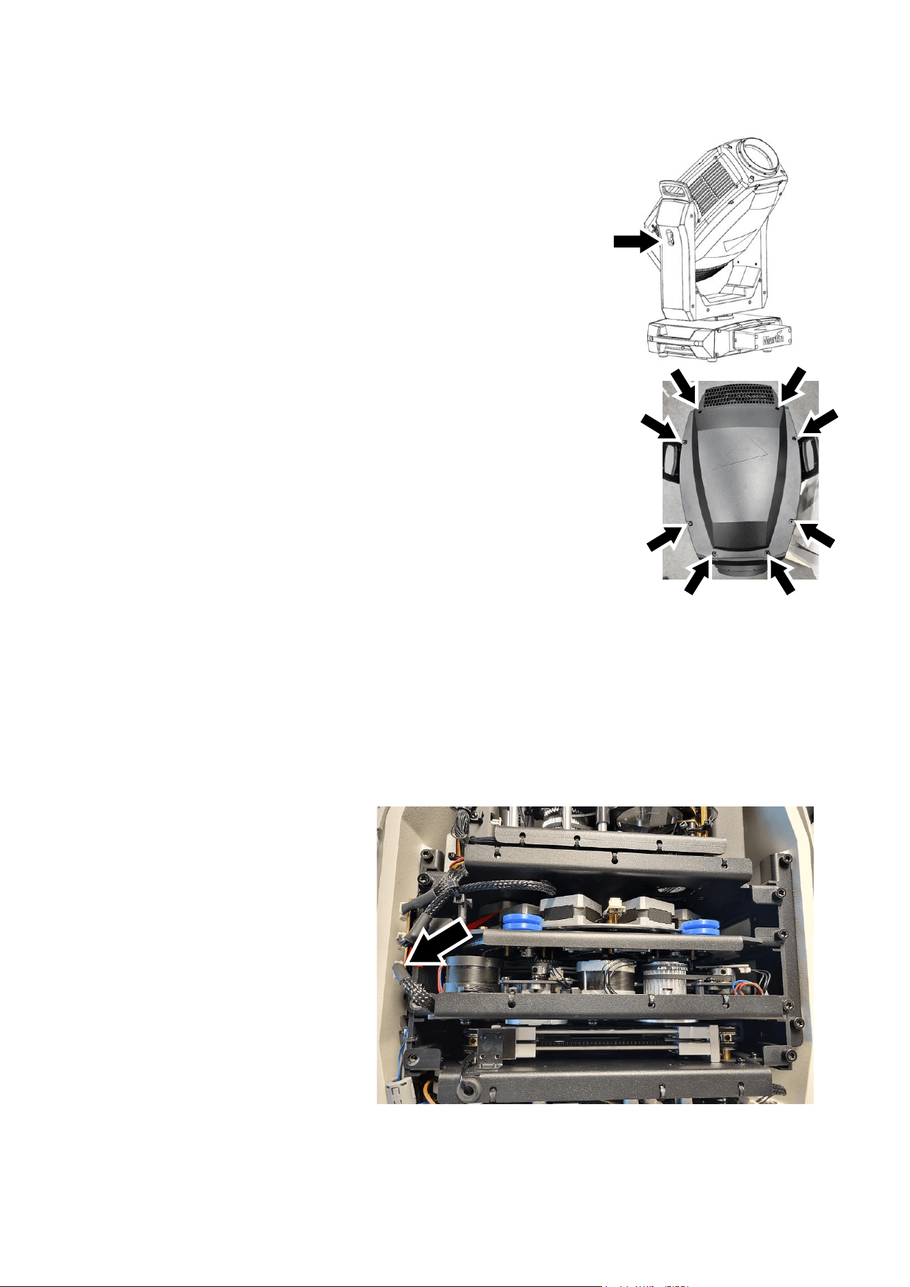
Martin
®
ERA 700 Performance IP User Manual Rev. F 49
Opening the head for access
To open the head for access to the rotating gobos:
1. Disconnect the fixture from power and allow to cool for 30
minutes.
2. Place the fixture on a suitable work surface.
3. See illustration on right. Apply the tilt lock (arrowed).
4. See photo on right. Remove the eight retaining screws (arrowed)
from the top or bottom head cover and lift the cover away from the
head slightly.
5. Remove the other head cover in the same way.
Closing the head
When closing the head, follow the above procedure in reverse. Tighten
all eight screws down loosely at first, then use a torque driver to tighten
them down fully to a torque of 2 Nm. As soon as the screws are
tightened enough for the cover to rest fully on its coated metal sealing
surface, the seal is compressed and the head cover is correctly installed.
Do not overtighten.
Important! In order to maintain the fixture’s IP65/IP66 rating, it is necessary to check that all seals and
screws are present and correctly positioned by carrying out a vacuum test each time you have opened
a top and/or bottom head cover. See ‘Vacuum testing after opening the fixture’ on page 53 for
instructions on carrying out this test. The product warranty does not cover humidity damage if a top or
bottom head cover has been removed and reinstalled without checking that it is perfectly sealed.
Release the tilt lock before reapplying power or packing the fixture in its flightcase.
Gobo replacement procedure
To replace a rotating gobo:
1. Remove both head covers as
described under ‘Opening the
head for access’ above.
2. See photo on right. Unplug the
main effects module connector
(arrowed) and disconnect it
from the PCB on the left of the
head. Remove the two Torx 25
screws from each side of the
top of the effects module and
lift the module carefully up and
out of the head. If any wires or
components become caught,
move them out of the way.
0
0
0
0
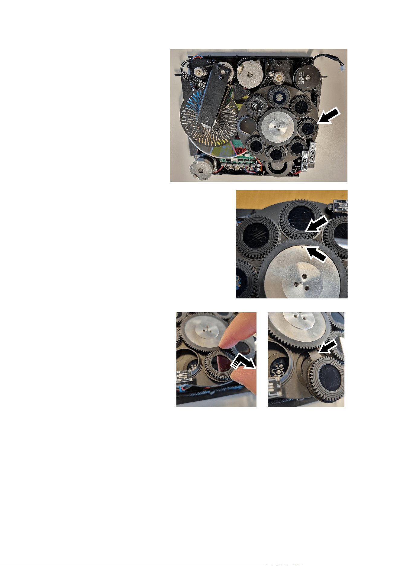
50 Martin
®
ERA 700 Performance IP User Manual Rev. F
3. Place the effects module on a
clean work surface with the rotating
gobo wheel facing upwards.
4. See photo on right. Move the gobo
that you want to replace to the
edge of the effects module as
shown.
5. See photo on right. Note the position of the reference
marks (arrowed) in the gobo drive wheel and goboholder.
Before you remove a goboholder from the wheel, turn the
drive wheel (twice if necessary) until the marks exactly
line up.
We recommend that you only remove one goboholder at
a time.
Avoid turning the drive wheel while a goboholder is out of
the gobo wheel. This will keep the gobos in their correct
orientation, avoiding the need to reprogram cues or adjust
gobo positions in the fixture because a gobo orientation
has changed during service. Note that, if necessary, you
can adjust the home positions of rotating gobos at any
time using the SERVICE → CALIBRATION menu in the
control panel.
6. See photos on right. With the
reference marks lined up, lift the
outside edge of the goboholder up
slightly and pull the goboholder out of
the gobo wheel. Note how the
goboholder tongue (arrowed)
engages in a recess in the gobo drive
wheel. You will need to reinstall the
goboholder with the tongue in the
same position in the drive wheel.
7. For details of removing and installing gobos in goboholders, see the next section: ‘Installing a gobo
in a goboholder’.
8. When reinstalling a goboholder in the gobo wheel, use the above procedure in reverse as a guide.
Line up the reference marks in the goboholder and gobo drive wheel and push the tongue correctly
into its location in the gobo drive wheel when you install the goboholder. Check that the goboholder
is held securely in the wheel after you have installed it.
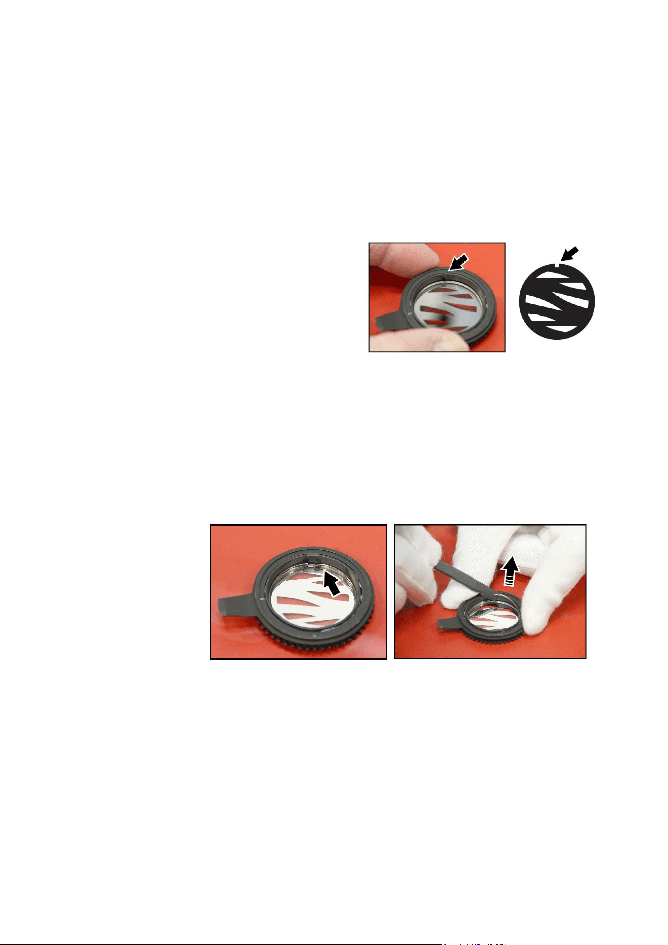
Martin
®
ERA 700 Performance IP User Manual Rev. F 51
Installing a gobo in a goboholder
All the rotating gobos in the ERA 700 Performance IP are held in their holders by springs and can be
removed from their holders as described in this section.
Avoid getting grease from your fingers or dirt onto gobos. Hold gobos by their edges only. Wear nitrile
cleanroom gloves when handling gobos.
Note that the textured glass gobo Limbo (Crystal) on Gobo Wheel 1 has a specially designed
goboholder to cater for the extra thickness of the fused glass and is glued into its goboholder. Textured
glass gobos and their goboholders are not interchangeable with the other gobos and goboholders.
Aligning gobos in goboholders
See illustration on right. Note the position of the
alignment marks (arrowed) on goboholders and
gobos. Install gobos with the alignment marks next
to each other.
With reference to the goboholder in the ERA 700
Performance IP:
• The side of the goboholder with the gobo
retaining spring faces towards the LED light
source.
• The side of the goboholder with the teeth faces towards the front glass.
• The shiny side of the gobo must face towards the spring in the goboholder so that it will face
towards the LED light source. The white side of the gobo must face away from the spring.
• Images or text on gobos must appear correctly (and not flipped left to right) when looking at the
goboholder from the side with the spring.
• The textured side of textured glass gobos must face towards the spring. The flat side of textured
gobos must face downwards so that the gobo sits flat in the goboholder.
Replacing a gobo
To replace a gobo in a goboholder:
1. See illustrations
on right. Place
the goboholder
on a clean
surface with the
teeth side facing
downwards.
Note the
position of the
bend (arrowed)
in the end of the
gobo retaining
spring. Using a plastic lever to avoid scratching the gobo, lever the end of the retaining spring out
of the groove in the goboholder and lift the retaining spring out of the goboholder.
2. Turn the goboholder teeth side up and let the gobo fall out of the holder onto a clean, soft surface.
Put the goboholder on the surface teeth side down again.
3. Holding the new gobo by its edges, insert it into the goboholder with the alignment marks on gobo
and goboholder oriented correctly with the shiny side facing upwards. Check that the gobo is fully
seated in the holder.
4. Insert the retaining spring into the goboholder and press it into its groove in the goboholder. Check
that the spring is pressed as flat as possible against the gobo and that the gobo is held securely.
5. Reinstall the goboholder in the gobo wheel, reinstall the effects module and reinstall the head
covers using the instructions given earlier in this section as a guide.
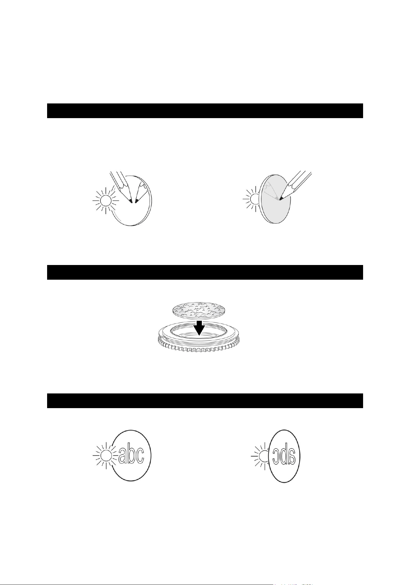
52 Martin
®
ERA 700 Performance IP User Manual Rev. F
Gobo orientation guide
Install gobos facing in the correct direction, or they may suffer heat damage. The orientations shown in
the following table are correct in most cases, but consult your Martin dealer or gobo supplier if you are
in any doubt about the orientation of a specific gobo type.
Coated Glass Gobos
The heavy matted aluminum coated borosilicate gobos in the ERA 700 Performance IP are factory-
installed with the more reflective sides facing towards the LED light source. Replacement gobos must
also be installed with more reflective sides facing the LEDs in order to avoid heat damage.
More reflective side towards LEDs
To minimize the risk of gobo overheating and
damage, turn the more reflective side of a coated
gobo towards the light source.
Less reflective side away from LEDs
The less reflective side of a coated gobo will
absorb less heat if it faces away from the light
source.
Textured Glass Gobos
Flat side towards goboholder
Textured glass gobos sit most squarely in the goboholder with the flat side placed down into the
recess in the goboholder. If in doubt, consult your Martin dealer or gobo supplier. We recommend that
textured glass gobos are glued into the goboholder.
Image / Text Gobos
True image towards LEDs
Reversed image away from LEDs
Gobos that have a specific left/right orientation (such as text gobos) will appear correctly in the
projection of the ERA 700 Performance IP if they appear correctly when viewed from the side that
faces towards the LED light source.
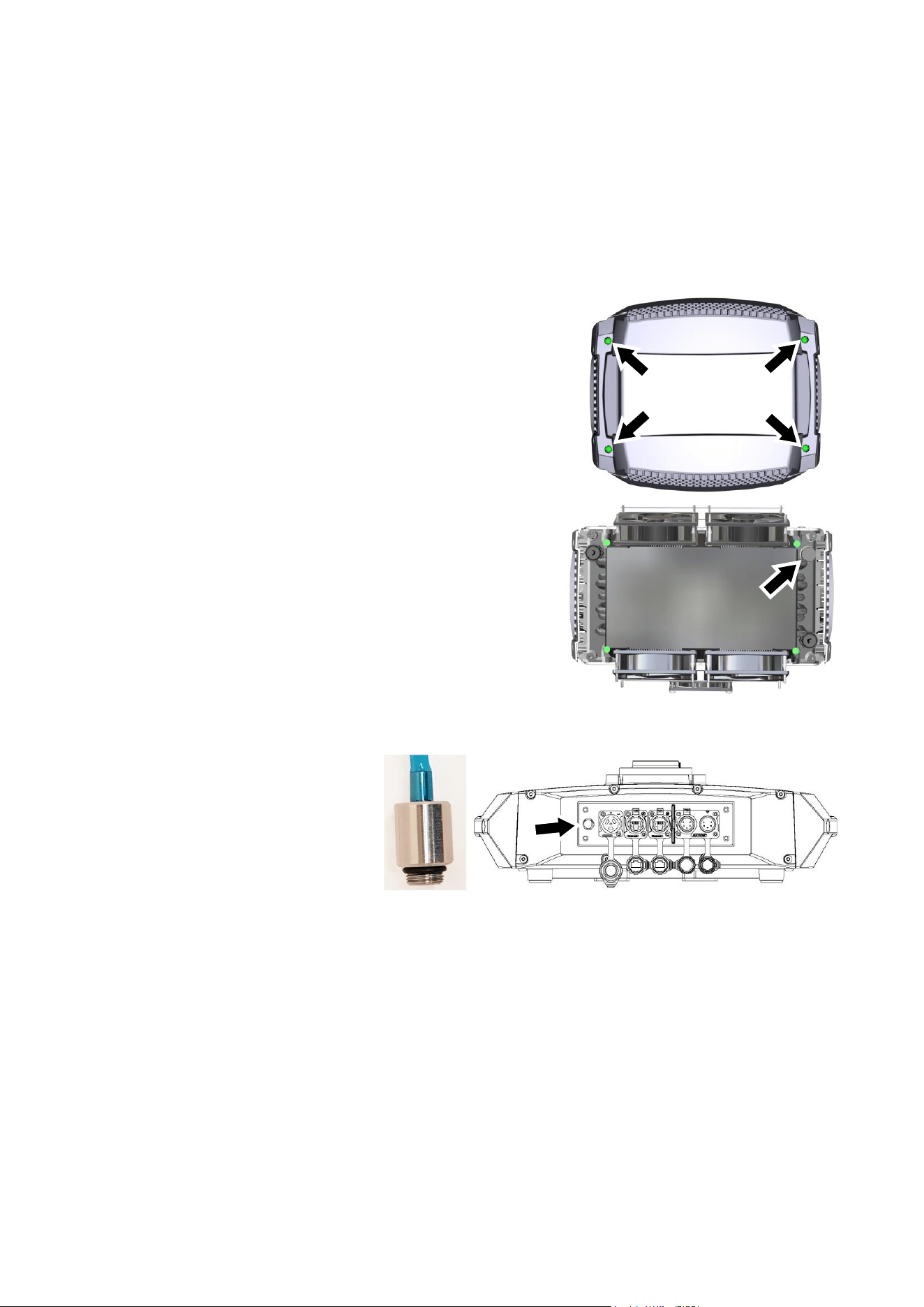
Martin
®
ERA 700 Performance IP User Manual Rev. F 53
Vacuum testing after opening the fixture
Each time you open a top or bottom head cover for service operations such as gobo replacement, it is
essential to reinstall all screws and all seals correctly in order to maintain the fixture’s IP65/IP66 rating.
The fixture’s product warranty does not cover water damage resulting from a fixture that has been
opened and incorrectly sealed.
To help you check that the head covers are fastened and sealed correctly, we strongly recommend that
you test the fixture using the Exterior Product Vacuum Tester available from Martin and a suitable
vacuum pump. You can find details of the tester and instructions for carrying out the test on
www.martin.com.
To test that the fixture is sealed correctly:
1. Disconnect the fixture from power and allow to cool if
necessary.
2. See illustration on right. Remove the four Torx 20 screws
(arrowed) from the cover on the back of the head and
remove the cover.
3. See illustration on right. Unscrew the pressure relief valve
(arrowed) from the back of the head and plug its threaded
hole temporarily with an M12 bolt, standard 1.5 thread
pitch, with a rubber O-ring, 2 mm thickness. If you do not
have an O-ring you can also use PTFE tape wrapped
around the bolt. The bolt must protrude minimum 10 mm
and maximum 25 mm into the head when fastened.
Alternatively you can take an old pressure relief valve,
seal the valve membrane with glue and allow the glue to
dry, then use this sealed pressure relief valve as a plug to
seal the hole. Check that the valve’s rubber washer is
present and in good condition.
4. See illustration on right.
Remove the pressure relief
valve (arrowed) from the
connections panel in the base
of the fixture and screw the
M12 (1.5 mm thread pitch)
sized vacuum hose adapter
and rubber O-ring supplied
with the Martin Vacuum Tester
into the base in place of the pressure relief valve with your fingers until the adapter is firmly finger-
tight.
5. Carry out the vacuum test following the instructions supplied with the Martin Tester and available
for download from the Tools area of www.martin.com. The correct test value for the ERA 700 IP is
-50 kPa (-0.5 Bar) which is allowed to fall to -45 kPa (-0.45 Bar) during the test period.
6. If the fixture passes the test, reinstall the pressure relief valves in the base and the back of the
head, using a torque driver to tighten to 0.6 – 0.8 Nm. Then reinstall the rear head cover using its
four Torx 20 screws. If the fixture does not pass the test, check that the adaptor is correctly
fastened into the base and that there are no leaks in the vacuum hose, and check that the top and
bottom head cover seals and screws are correctly installed. If the fixture continues to fail the test,
seek advice from a Martin Service agent.
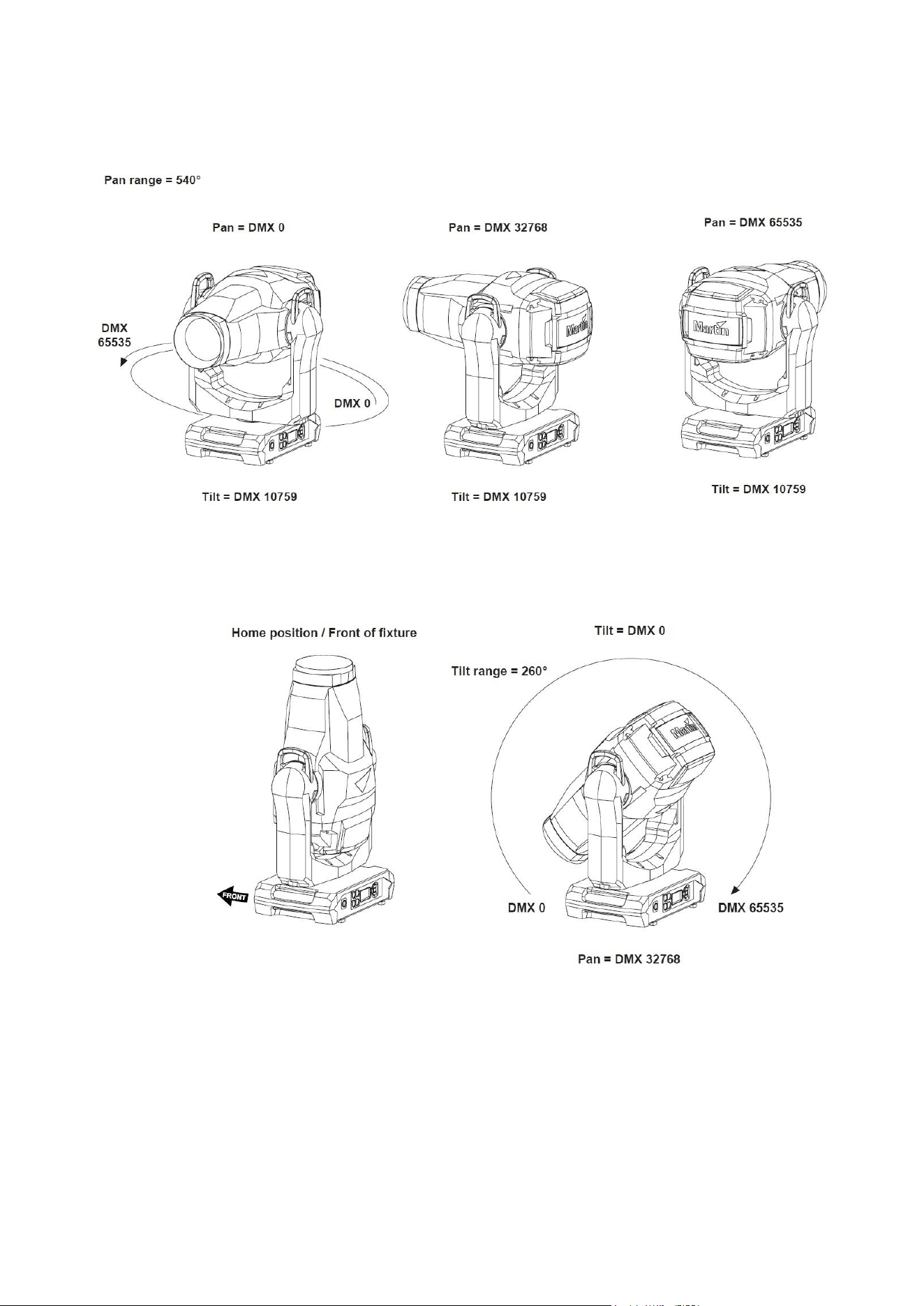
54 Martin
®
ERA 700 Performance IP User Manual Rev. F
Pan/tilt and zoom orientation guide
Fixture shown in illustrations is for example purposes only
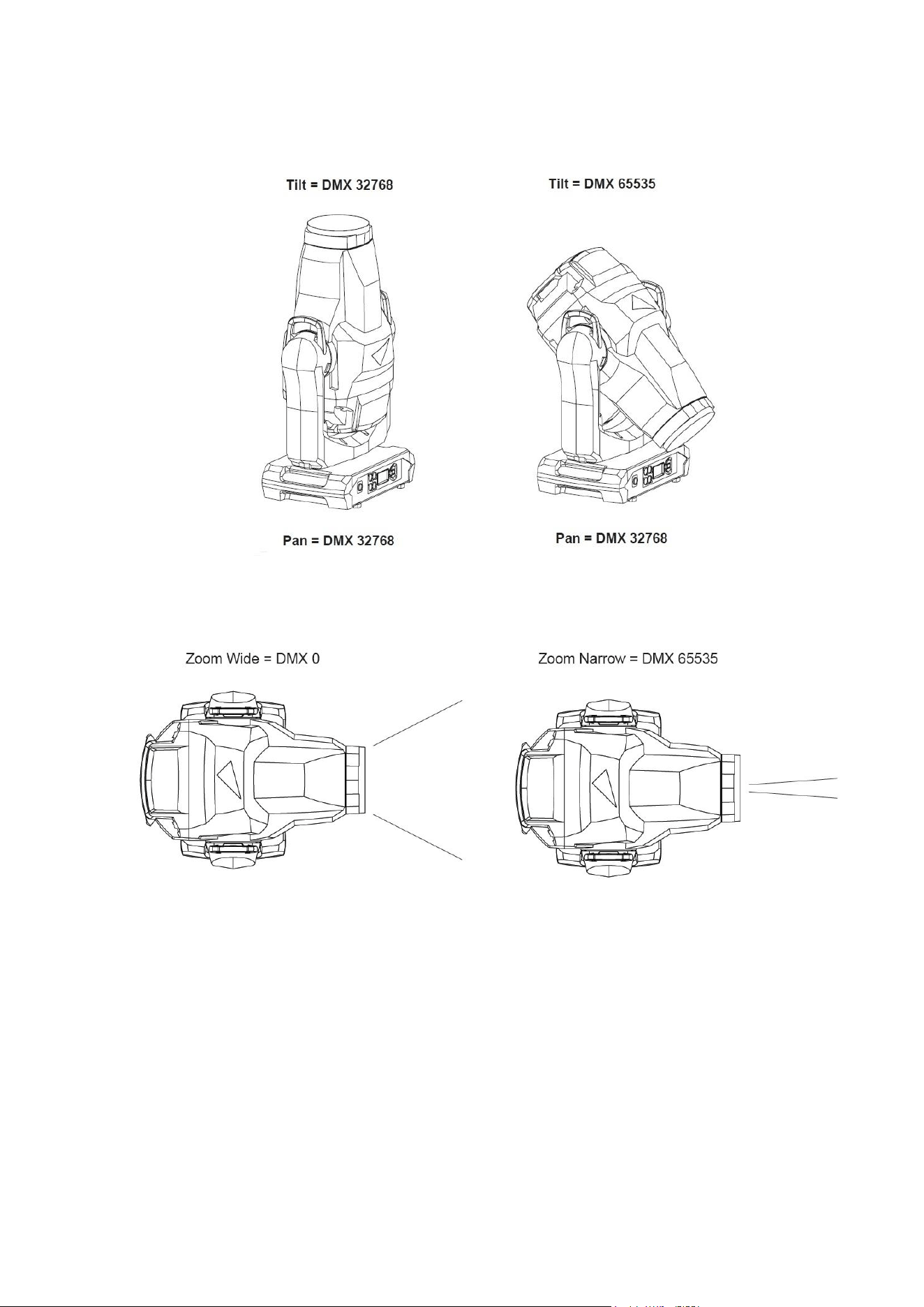
Martin
®
ERA 700 Performance IP User Manual Rev. F 55
Fixture shown in illustrations is for example purposes only
56 Martin
®
ERA 700 Performance IP User Manual Rev. F
Disposing of this product
Martin® products are supplied in compliance with Directive
2012/19/EC of the European Parliament and of the Council of the
European Union on WEEE (Waste Electrical and Electronic
Equipment), where applicable. Help preserve the environment!
Ensure that this product is recycled at the end of its life. Your
supplier can give details of local arrangements for the disposal of
Martin products.
Compliance and specifications
See the Safety and Installation Manual attached to this user manual for details of this product’s
compliance with national and international standards, FCC rules etc. See the Martin website at
www.martin.com for technical specifications for this product.

www.martin.com
ERA 700 Performance IP
Safety and Installation Manual
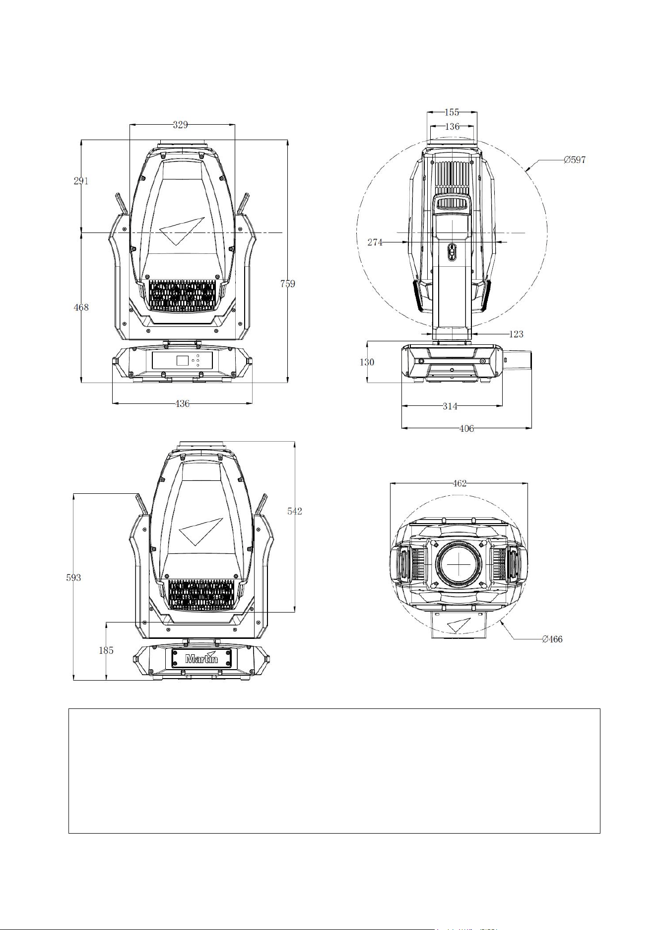
Dimensions
All dimensions are in millimeters
©2023-2025 HARMAN PROFESSIONAL DENMARK ApS. All rights reserved. Features, specifications and appearance are subject
to change without notice. HARMAN PROFESSIONAL DENMARK ApS and all affiliated companies disclaim liability for any injury,
damage, direct or indirect loss, consequential or economic loss or any other loss occasioned by the use of, inability to use or reliance
on the information contained in this document. Martin is a registered trademark of HARMAN PROFESSIONAL DENMARK ApS
registered in the United States and/or other countries.
HARMAN PROFESSIONAL DENMARK ApS, Olof Palmes Allé 44, 8200 Aarhus N, Denmark
HARMAN PROFESSIONAL, INC., 8500 Balboa Blvd., Northridge CA 91325, USA
www.martin.com
ERA 700 Performance IP Safety and Installation Manual English, Revision F

Martin
®
ERA 700 Performance IP Safety and Installation Manual Revision F 3
Table of contents
Dimensions ................................................................................................................. 2
Safety information ....................................................................................................... 4
Précautions d’emploi ................................................... Error! Bookmark not defined.
Sicherheitshinweise .................................................... Error! Bookmark not defined.
Información de seguridad ............................................ Error! Bookmark not defined.
Introduction ................................................................................................................. 9
Before using the product for the first time ........................................................ 9
Applying mains power ...................................................................................... 9
Packing and unpacking .................................................................................... 9
Fixture overview ........................................................................................................ 10
Physical installation ................................................................................................... 11
Installation location ........................................................................................ 11
Avoiding damage from other light sources ..................................................... 11
Standing the fixture on a flat surface .............................................................. 11
Mounting the fixture on a truss ....................................................................... 11
Fastening the fixture to a structure or surface ................................................ 12
Securing with a safety cable .......................................................................... 13
AC mains power ........................................................................................................ 14
Connecting to power ...................................................................................... 14
Installation physique .................................................... Error! Bookmark not defined.
Emplacement d'installation .............................. Error! Bookmark not defined.
Dommages causés par d’autres sources de lumièreError! Bookmark not defined.
Positionnement de l’appareil sur une surface planeError! Bookmark not defined.
Montage du luminaire sur une structure ........... Error! Bookmark not defined.
Fixation de l’’appareil à une structure ou une surfaceError! Bookmark not defined.
Alimentation ................................................................ Error! Bookmark not defined.
Connexion à l'alimentation ............................... Error! Bookmark not defined.
Montage ...................................................................... Error! Bookmark not defined.
Installationsort .................................................. Error! Bookmark not defined.
Vermeidung von Schäden durch andere LichtquellenError! Bookmark not defined.
Aufstellen des Geräts auf einer ebenen Fläche Error! Bookmark not defined.
Montage des Geräts an einem Träger ............. Error! Bookmark not defined.
Montage des Fangseils .................................... Error! Bookmark not defined.
Wechselstromquelle .................................................... Error! Bookmark not defined.
Anschluss an die Stromquelle .......................... Error! Bookmark not defined.
Instalación física .......................................................... Error! Bookmark not defined.
Ubicación de la instalación .............................. Error! Bookmark not defined.
Colocar el dispositivo sobre una superficie planaError! Bookmark not defined.
Montar el dispositivo en un truss ...................... Error! Bookmark not defined.
Fijación del equipo a una estructura o superficieError! Bookmark not defined.
Asegurar con un cable de seguridad ............... Error! Bookmark not defined.
Alimentación AC .......................................................... Error! Bookmark not defined.
Conexión a la alimentación .............................. Error! Bookmark not defined.
Maintenance .............................................................................................................. 15
Cleaning ......................................................................................................... 15
Uploading new firmware ................................................................................ 15
Service and repairs ........................................................................................ 16
4 Martin
®
ERA 700 Performance IP Safety and Installation Manual Revision F
Safety information
WARNING!
Read the safety precautions in this manual before installing,
powering, operating or servicing this product.
The following symbols are used to identify important safety information on the product and in this manual:
Warning!
Safety hazard.
Risk of severe
injury or death.
Warning!
Hazardous
voltage. Risk
of lethal or
severe electric
shock.
Warning!
Fire hazard.
Warning!
Burn hazard.
Hot surface.
Do not touch.
Warning!
Intense light
emission.
Warning!
See user documentation.
Warning! Risk Group 3 product according to EN 62471 and Risk Group 2 product according
to EN 62471, IEC/TR 62778 (see “Protection from eye injury” on page 7 for full details).
Possibly hazardous radiation emitted from this product. May be harmful to the eyes. Do not
stare directly into the light output from the product. Position the product so that prolonged
staring into the product at a distance closer than 9 m (29.6 ft.) is not expected. Do not view
the light output with optical instruments or any device that may concentrate the beam.
This lighting fixture presents risks of severe injury or death due to fire and burn hazards,
electric shock and falls if the safety precautions in this manual are not followed.
Only qualified technicians are permitted to open the fixture. Users may carry out external
cleaning as described in this manual, following the warnings and instructions provided, but
any service operation not described in this manual or in the fixture’s User Manual must be
referred to an authorized Martin service technician.
Read this manual before installing, powering, operating or servicing the fixture. Follow the
safety precautions and observe all warnings in this Safety and Installation Manual, in the
fixture’s User Manual, and printed on the fixture.
The ERA 700 Performance IP is for professional use as a stage light only. It is not for
household or general lighting applications. Respect all locally applicable laws, codes and
regulations when installing, powering, operating or servicing the fixture.
The light source contained in this fixture must be replaced by Martin
®
Service or an
authorized Martin Service partner only.
Install, operate and service Martin products only as directed in their user documentation, or
you may create a safety hazard or cause damage that is not covered by product warranties.
The latest versions of this Safety and Installation Manual and the fixture’s User Manual are
available for download from the ERA 700 Performance IP area of the Martin website at
www.martin.com. Before you install, operate or service the fixture, check the Martin website
and make sure that you have the latest user documentation for the fixture. Document
revisions are indicated at the bottom of page 2.
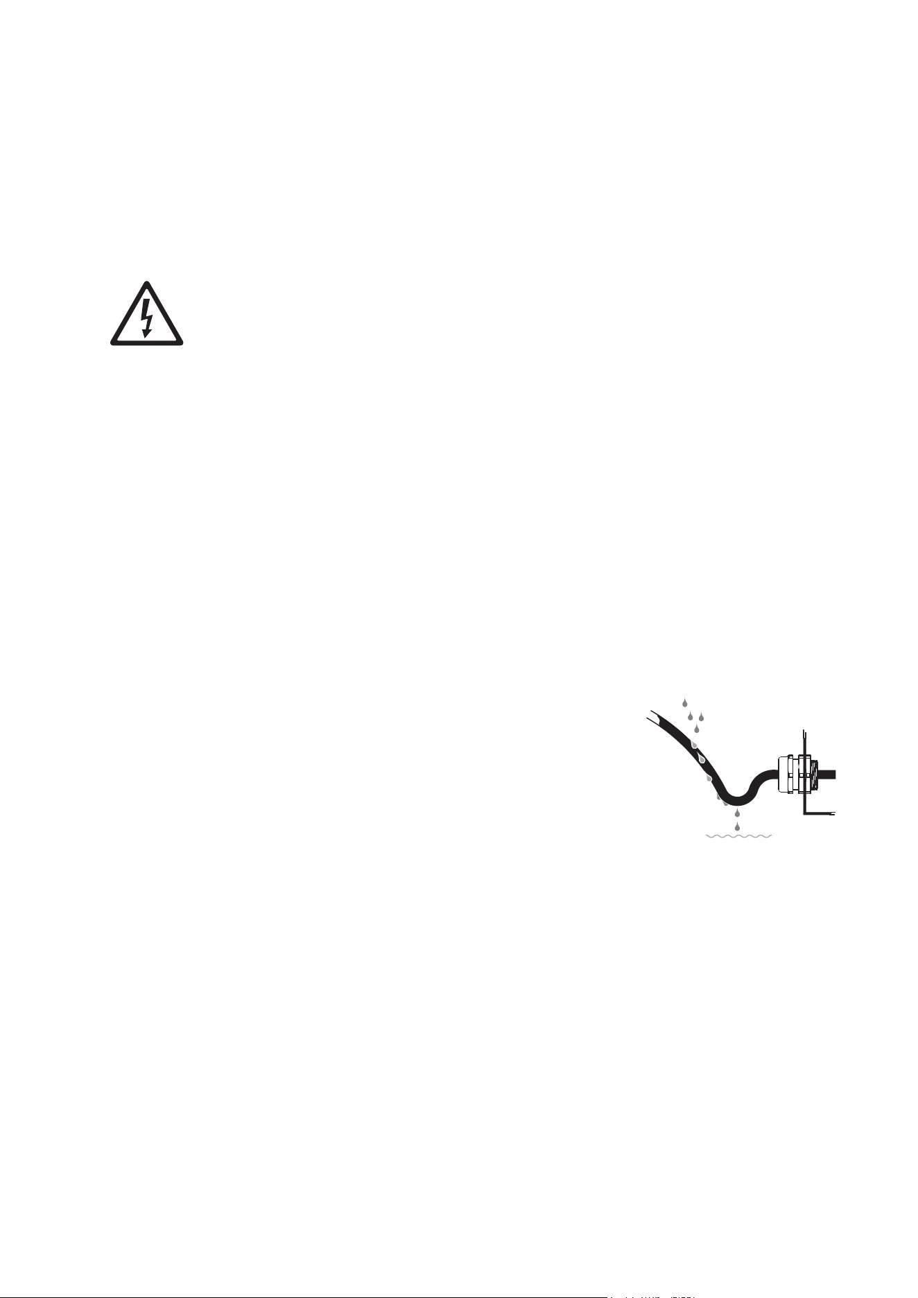
Martin
®
ERA 700 Performance IP Safety and Installation Manual Revision F 5
Technical Support
If you have questions about how to install or operate the fixture safely, please contact
Harman Professional Technical support:
• For technical support in North America, please contact
HProTechSupportUSA@harman.com
Phone: (844) 776-4899
• For technical support outside North America, please contact your national distributor.
Protection from electric shock
The ERA 700 Performance IP has an ingress protection rating of:
• IP66 if the anti-tamper box is installed on the connections panel with the cable openings
facing downwards, and
• IP65 without the anti-tamper box.
To achieve an IP66 rating, keep the fixture’s anti-tamper box installed over the connections
panel with the cable openings in the anti-tamper box facing downwards at all times. Remove
the box only temporarily for access to the connectors during installation or maintenance
work.
The fixture can withstand rain, splashing water, condensation etc. The fixture is designed to
be used under any weather conditions, but do not expose it to an artificially high volume of
water (in a fountain, waterfall or shower, for example). Do not immerse it. Do not expose it to
high-pressure water jets. Isolate the fixture from power immediately if extreme conditions
such as flooding arise.
The fixture is rated IP65/IP66 only when connectors with a corresponding IP rating are used
on cables connected to the fixture.
Use only connectors and cables that are suitable for the installation environment and
application with respect to humidity, water and sunlight resistance.
The power and data connectors are fitted with rubber caps to protect from water ingress.
Keep rubber caps installed at all times on all connectors that are not in use.
Arrange cables so that they arrive at connectors from below.
Create a ‘drip loop’ if necessary (see drawing on right). With
this arrangement, gravity will cause any condensation or
water droplets to run away from connectors.
Support the weight of cable runs. Do not allow a length of
cable to hang from a connector.
In wet locations, install the fixture with the connections panel
facing downwards.
The fixture accepts AC mains power at 100-240 V~
(nominal), 50/60 Hz. Do not connect the fixture to mains
power that is not within this range.
The fixture has a maximum total power consumption of 990 W.
The fixture draws a maximum total current of 11.1 A at 100-120 V~ and a maximum total
current of 3.7 A at 200-240 V~.
The fixture draws a typical half-cycle RMS inrush current of 14.0 A for the first 10
milliseconds when mains power is first applied to the fixture at 230 V~, 50 Hz.
To connect the fixture to mains power, you must first obtain 12 AWG or 2.5 mm
2
power input
cable that is 16 A rated and temperature-rated to suit the installation environment. In the
USA and Canada, the cable must be UL-listed, type SJTW or equivalent. In the EU, the
cables must be type H05VV-F or equivalent. Suitable cables with the correct connectors are
available from Martin.
Drip loop
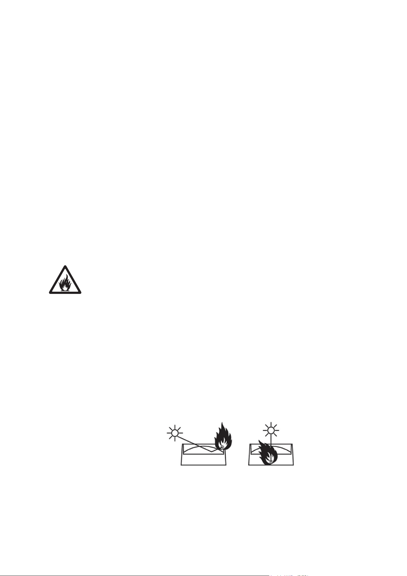
6 Martin
®
ERA 700 Performance IP Safety and Installation Manual Revision F
Ensure that the fixture is electrically connected to ground (earth) via the power input cable.
Do not remove the protective coating on the housing or loosen screws to establish a
separate ground (earth) connection from the fixture’s chassis.
Use only a source of mains power that complies with local building and electrical codes and
has both overload and ground-fault (earth-fault) protection.
Socket outlets or external power switches used to supply the fixture with power must be
located near the fixture and easily accessible so that the fixture can easily be disconnected
from power.
Disconnect the fixture from AC mains power before carrying out any installation, cleaning or
maintenance work and when the fixture is not in use.
Isolate the fixture from power immediately if the power plug or any seal, cover, cable, or
other component is damaged, defective, deformed, showing signs of water ingress or
showing signs of overheating. Do not reapply power until repairs have been completed.
Before using the fixture, check that all power distribution equipment and cables are in
perfect condition and rated for the electrical requirements of all connected devices.
Do not connect a device to power if its maximum current draw will exceed the electrical
ratings of any cable or connector used in the chain.
Do not remove any cover from the fixture.
Do not cover, immerse or block the pressure equalization valve on the fixture’s connections
panel. Check the pressure equalization valve periodically. If it appears dirty it may be
becoming blocked. Contact an authorized Martin service agent for possible replacement.
Do not use this equipment at an altitude of more than 2000 m (6570 ft.) above sea level.
Protection from burns and fire
Do not operate the fixture if the ambient temperature (T
a
) exceeds 50° C (122° F). At this
temperature, a thermal protection system shuts the fixture down automatically.
The surface of the fixture can reach up to 70° C (158° F) during operation. Avoid contact by
persons and materials. Allow the fixture to cool for at least 15 minutes before handling.
Keep flammable materials well away from the fixture. Keep all combustible materials (e.g.
fabric, wood, paper) at least 0.5 m (1.7 ft.) away from the fixture.
Ensure that there is free and unobstructed airflow around the fixture. Provide a minimum
clearance of 0.5 m (1.7 ft.) around fans and air vents.
Do not use the fixture to illuminate surfaces within 2 m (6.6 ft.) of the fixture.
Do not stick filters, masks or other materials onto any optical component.
See drawing below. The fixture’s lenses can focus the sun’s rays inside the fixture, creating
a risk of fire and damage. Do not expose the front of the fixture to sunlight or any other
source of powerful light from any angle, even for a few seconds. Make sure that the head
will be pointing away from the sun and from any other potential source of powerful light at all
times, even when the fixture is not in use.
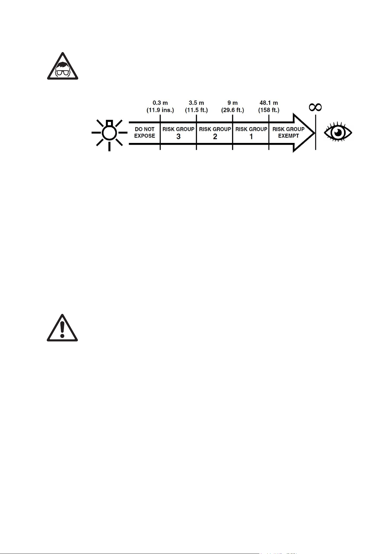
Martin
®
ERA 700 Performance IP Safety and Installation Manual Revision F 7
Protection from eye injury
This fixture corresponds to Risk Group 3 according to EN 62471 when all photobiological
risks are considered and Risk Group 2 according to IEC/TR 62778 for blue light only. It
emits possibly hazardous optical radiation. It falls into the Risk Group categories shown
below according to EN 62471 and IEC/TR 62778 under worst-case conditions:
At a distance of less than 3.5 m (11.5 ft.) from the fixture, the light output can potentially
cause eye or skin injury before an exposed person's natural aversion responses (blink reflex
and reaction to skin discomfort) can protect them. At distances greater than 3.5 m (11.5 ft.),
potential eye and skin injury hazards from the light output are normally prevented by natural
aversion reflexes.
Position the fixture so that persons cannot be exposed to the fixture's light output at a
distance of less than 3.5 m (11.5 ft.) from the fixture and so that prolonged staring into the
light output at less than 9 m (29.6 ft.) is not expected.
Do not look directly into the fixture’s light output.
Do not look at the light output with magnifiers, telescopes, binoculars or similar optical
instruments that may concentrate the light output.
Ensure that persons are not looking directly into the front of the fixture when the product
lights up suddenly. This can happen when power is applied, when the product receives a
DMX signal, or when certain control menu items are selected.
Disconnect the fixture from power at all times when the fixture is not in use.
Provide well-lit conditions to reduce the pupil diameter of anyone working on or near the
fixture.
Protection from injury
The fixture weighs 39.7 kg (87.6 lbs.) not including rigging hardware.
When the fixture is in use, it must be either:
• fastened to a secure, stable structure such as a rigging truss, or
• standing on a stable horizontal surface where it will not present a danger of tripping or
falling.
Install the fixture only as directed in this manual.
The fixture is not portable when installed.
Ensure that any supporting structure and/or hardware used can hold at least six (6) times
the weight of all the devices they support.
Make sure that all supporting structures and rigging hardware items (including safety cables
and fasteners) are in perfect condition, safely dimensioned, suitable for the installation
environment and will be stable under all weather and temperature conditions.
If suspending from a rigging structure, fasten the fixture to a truss or similar support using
two rigging clamps and omega brackets. Do not use safety cables as the primary means of
support.
If the fixture is installed in a location where it may cause injury or damage if it falls, install as
directed in this manual a secondary attachment such as a safety cable that will hold the
fixture if a primary attachment fails. The secondary attachment must be approved by an
official body such as TÜV as a safety attachment for the weight that it secures, must comply

8 Martin
®
ERA 700 Performance IP Safety and Installation Manual Revision F
with EN 60598-2-17 Section 17.6.6 and must be capable of bearing a static suspended load
that is ten (10) times the weight of the fixture and all installed accessories.
If the safety cable attachment point becomes deformed, do not suspend the fixture. Have
the fixture repaired by an authorized Martin service partner.
Allow enough clearance around the head to ensure that it cannot collide with an object or
another fixture when it moves.
Check that all external covers and rigging hardware are securely fastened.
Block access below the work area and work from a stable platform whenever installing,
servicing or moving the fixture. Make sure that there is no risk of injury from falling parts,
tools or other materials.
Do not operate the fixture with missing or damaged covers, shields or any optical
component.
Do not lift or carry the fixture by its head. Support the fixture by its base only.
In the event of an operating problem, stop using the fixture immediately and disconnect it
from power. Do not attempt to use a fixture that is obviously damaged.
Do not modify the fixture in any way not described in this manual or install other than
genuine Martin parts.
Refer any service operation not described in this manual to Martin Service or an authorized
Martin service partner.

Martin
®
ERA 700 Performance IP Safety and Installation Manual Revision F 9
Introduction
Thank you for selecting the ERA 700 Performance IP moving head lighting fixture from Martin®.
This Safety and Installation Manual is supplied with the fixture. It gives details of installing and servicing
the fixture as well as connecting to mains power. The ERA 700 Performance IP User Manual, containing
full instructions for connecting to control data, setting up, controlling and monitoring the fixture, is available
for download from the ERA 700 Performance IP area of the Martin website at www.martin.com. If you
have any difficulty locating this document, please contact your Martin supplier for assistance.
Before installing, operating or servicing the ERA 700 Performance IP, please check the fixture’s area of
the Martin website at www.martin.com and make sure that you have the latest user documentation for the
product.
Not all product specifications are included in the fixture’s user documentation. You can find full
specifications for the fixture in the ERA 700 Performance IP area of the Martin website. The online
specifications include information to help you order accessories such as cables, flightcases etc.
The fixture is supplied with this Safety and Installation manual, an anti-tamper box to install over the
connections panel, and two Martin omega brackets for fastening a rigging clamp to the fixture base.
Before using the product for the first time
1. Check the support pages on the Martin Professional website at www.martin.com for the most recent
user documentation and technical specifications for the fixture. Martin user manual revisions are
identified by the revision letter at the bottom of the inside cover.
2. Read ‘Safety information’ on page 3 before installing, operating or servicing the fixture.
3. Unpack and ensure that there is no transportation damage before using the fixture. Do not attempt to
operate a damaged fixture.
4. Check that the voltage and frequency of the local power source match the mains power requirements
of the fixture.
5. Either hard-wire the fixture’s power input cable to an AC mains power source or install as described in
this manual a power plug (cord cap) that is suitable for local power outlets on the power input cable
and connect the cable to an AC mains power outlet. If you need to fabricate a power cable, use only
the cable and connector specified in this manual.
Applying mains power
The fixture does not have an on/off switch. It becomes active as soon as AC mains power is applied at the
power input connector. Be prepared for the head to move and for the fixture to suddenly emit bright light.
Each time power is applied to the fixture, it will reset all effects and functions to their home positions. A
reset typically takes around 20 seconds.
Packing and unpacking
Allow the fixture to cool for 30 minutes before packing it for storage or transport in a flightcase or
packaging. If the fixture is wet, we recommend that you dry it before packing to avoid moisture affecting
protective packaging and potentially causing mold.
If you move the fixture from a cold to a warm environment, remove it from its flightcase or packaging and
give it at least two hours to acclimatize before you apply power. This will help to avoid damage due to
internal condensation. If condensation is still visible inside the front glass, run the fixture’s dehumidification
function using the service menu. Note that you can also set the fixture to run the dehumidification function
automatically.
Shocks during transport can damage the tilt lock of a moving head fixture. Release the fixture’s tilt lock
and make sure that the head will be supported by a flightcase insert or packaging before storing or
transporting the fixture.
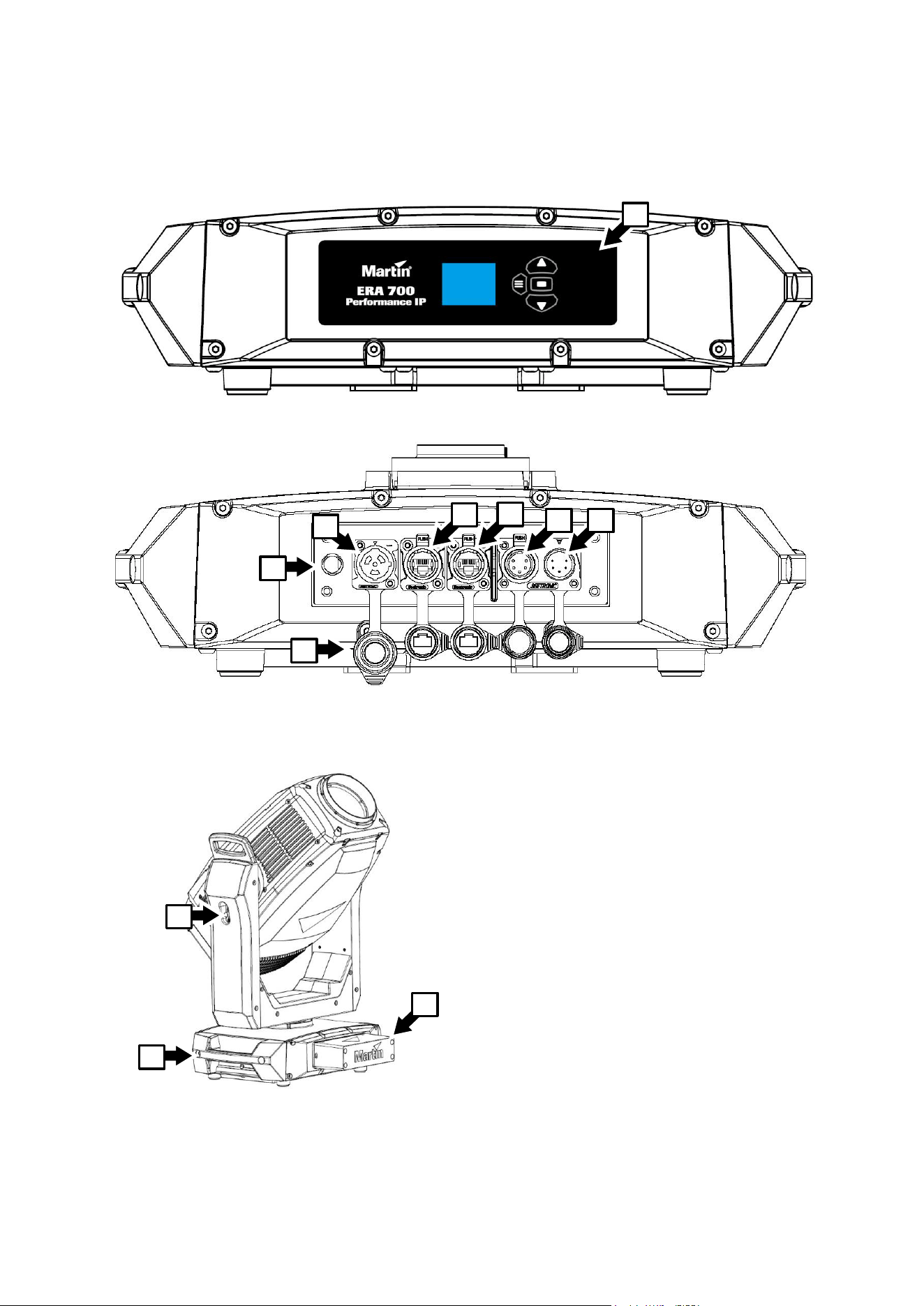
10 Martin
®
ERA 700 Performance IP Safety and Installation Manual Revision F
Fixture overview
A – Control panel
B – AC mains power input (accepts Neutrik
powerCON TRUE1 TOP or compatible)
C – Control data Ethernet port in/out
D – Control data Ethernet port in/out
E – DMX data input (5-pin locking male XLR)
F – DMX data thru / output (5-pin locking
female XLR)
G – Pressure equalization valve
H – Connector sealing caps (must be installed
on all unused connectors)
I – Tilt lock
J – Carrying handle
K – Anti-tamper box
A
F
E
C
D
B
G
H
I
J
K
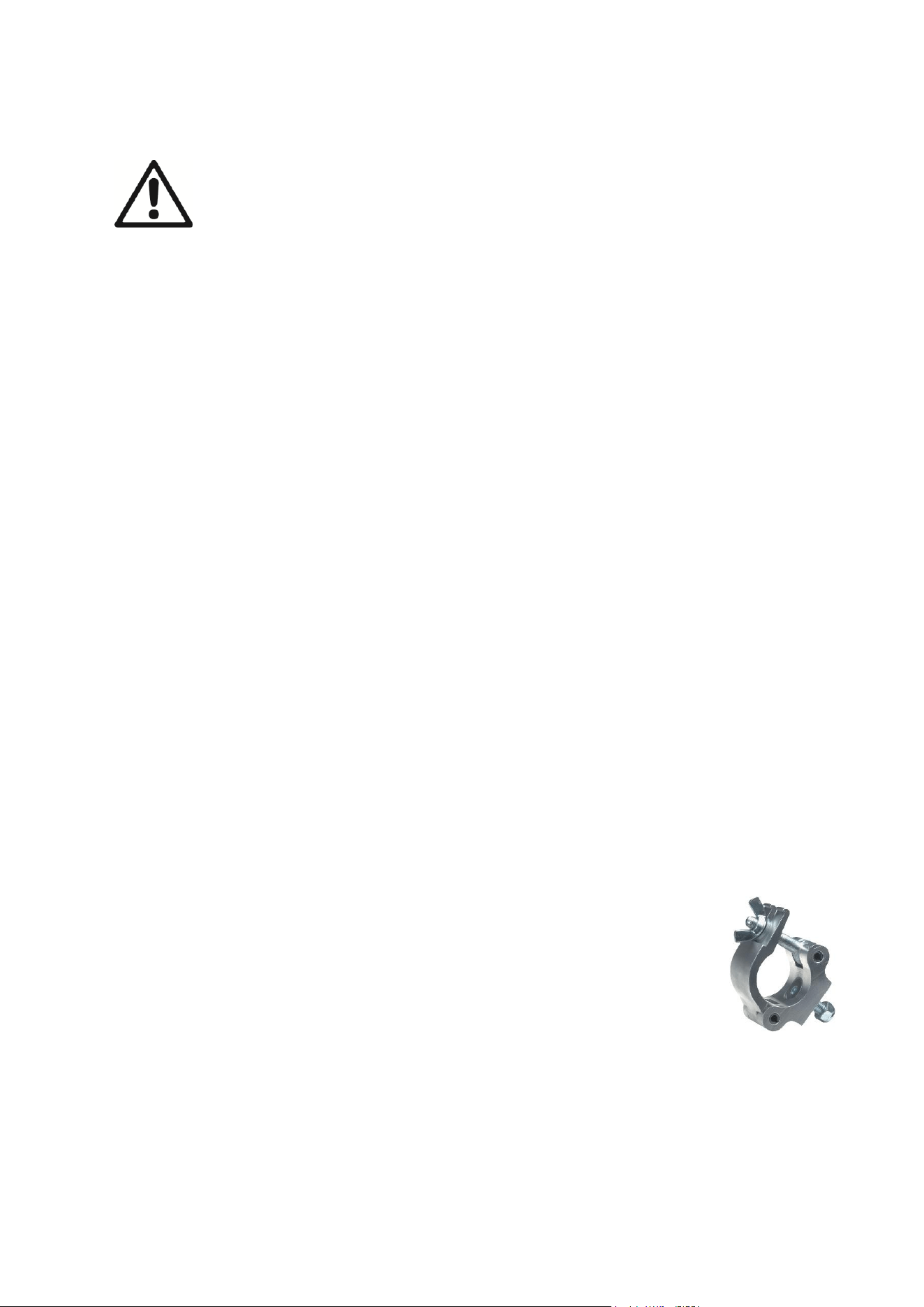
Martin
®
ERA 700 Performance IP Safety and Installation Manual Revision F 11
Physical installation
Warning! Read ‘Safety information’ on page 4 before installing the fixture.
To avoid head collisions when installing ERA 700 Performance IP fixtures next to
each other, allow a minimum center-to-center distance between fixtures of 590 mm
(23.3 inches).
Martin can supply installation hardware that is suitable for use with the fixture such as rigging clamps,
safety cables, and a kit containing four M12 threaded fastener blocks for use in permanent outdoor
installation (see the product specifications on the ERA 700 Performance IP product page on the Martin
website at www.martin.com).
We recommend that you keep the fixture’s anti-tamper box installed over the connections panel,
especially in permanent installations, to protect against accidental or unintended removal of connectors.
Installation location
The ERA 700 Performance IP is designed for permanent or temporary indoor or outdoor use. It can
withstand rain and splashing water, but do not allow it to become immersed in water.
Fasten the fixture to a secure structure or surface or stand it on a surface where it cannot be moved or fall
over. If you install the fixture in a location where it may cause injury or damage if it falls, secure it as
directed in this manual using a securely anchored safety cable that will hold the fixture if the primary
fastening method fails.
If installing the fixture outdoors, install the anti-tamper box over the fixture’s connections panel so that the
openings in the box face downwards. Ensure that cables arrive from below the fixture, creating ‘drip loops’
in cables if necessary.
In permanent outdoor installations, fasten the fixture securely to a stable structure or surface using the kit
containing M12 threaded fastener blocks that is available as an accessory from Martin suppliers.
Avoiding damage from other light sources
Do not point the light output from other lighting fixtures at the ERA 700 Performance IP, as powerful light
can damage the display.
Standing the fixture on a flat surface
The fixture can be placed on a hard, fixed, flat horizontal surface provided that there is no risk that it may
cause an obstruction or be knocked over. Ensure that the surface can support at least six (6) times the
weight of all items that it will support.
If you install the fixture in a location where it may cause injury or damage if it falls, secure it as directed in
this chapter with a securely anchored safety cable.
Mounting the fixture on a truss
In permanent indoor or temporary outdoor installations, the fixture can be clamped to a
truss or similar rigging structure in any orientation. Use a half-coupler type clamp (see
illustration on right) that completely encircles the truss chord or tubular support.
To clamp the fixture to a truss:
1. Check that the rigging structure can support at least six times (or more if required
by local regulations) the weight of all fixtures and equipment to be installed on it.
2. Block access under the work area.
3. The fixture is supplied with two omega-type brackets. Bolt two half-coupler type
rigging clamps that are in perfect condition and approved for the weight that each
clamp will support securely to the two brackets. Use M12, grade 8.8 steel minimum bolts with self-
locking nuts.
Half-coupler
clamp
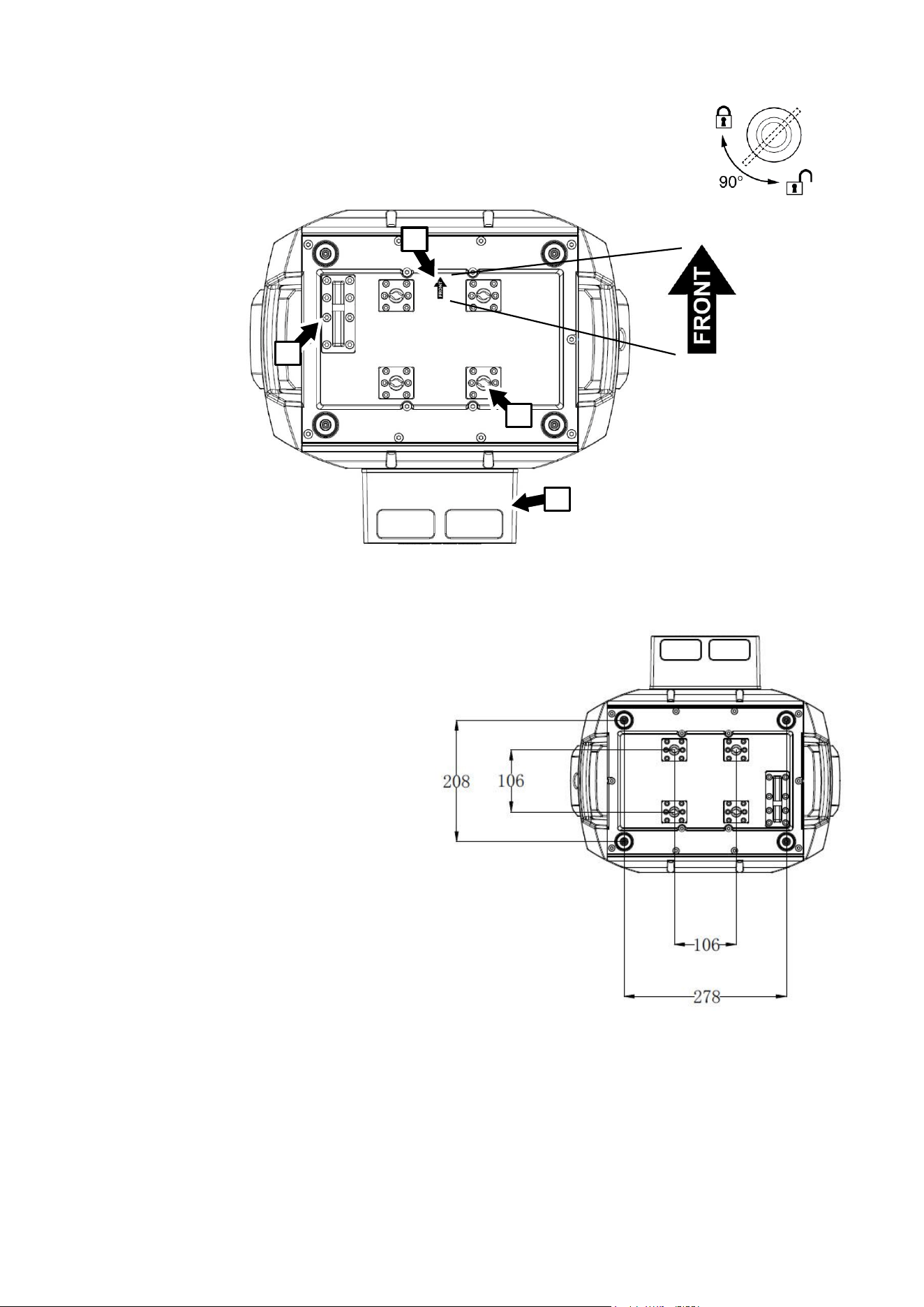
12 Martin
®
ERA 700 Performance IP Safety and Installation Manual Revision F
4. Fasten the omega brackets to the base of the fixture by locking the bracket’s
quarter-turn fasteners into the receptacles (see B in illustration below) in the base
of the fixture. Turn quarter-turn fasteners a full 90° to lock them as shown on right.
5. Note the position of the arrow marked FRONT (see A in illustration above). Working from a stable
platform, hang the fixture on the truss and
fasten the two rigging clamps onto the
truss with FRONT pointing towards the
main area to be illuminated.
6. If installing the fixture outdoors, make
sure that the openings for cables in the
anti-tamper box D face downwards.
7. Secure the fixture with a safety cable as
directed below.
8. Check that the head will not collide with
other fixtures or objects.
Fastening the fixture to a structure or
surface
In temporary or permanent indoor or outdoor
installations, the fixture can be fastened to a
secure structure or surface in any orientation
using the kit containing M12 threaded
fastener blocks that is available from Martin
as an accessory for the ERA 700 IP (see the
ERA 700 IP area of www.martin.com or
contact a Martin supplier for details).
To fasten the fixture to a surface or structure:
1. Obtain the M12 fastener blocks kit from a Martin supplier.
2. Check that the rigging structure or surface is secure and can support at least six times (or more if
required by local regulations) the weight of all fixtures and equipment to be installed on it.
A
B
D
C
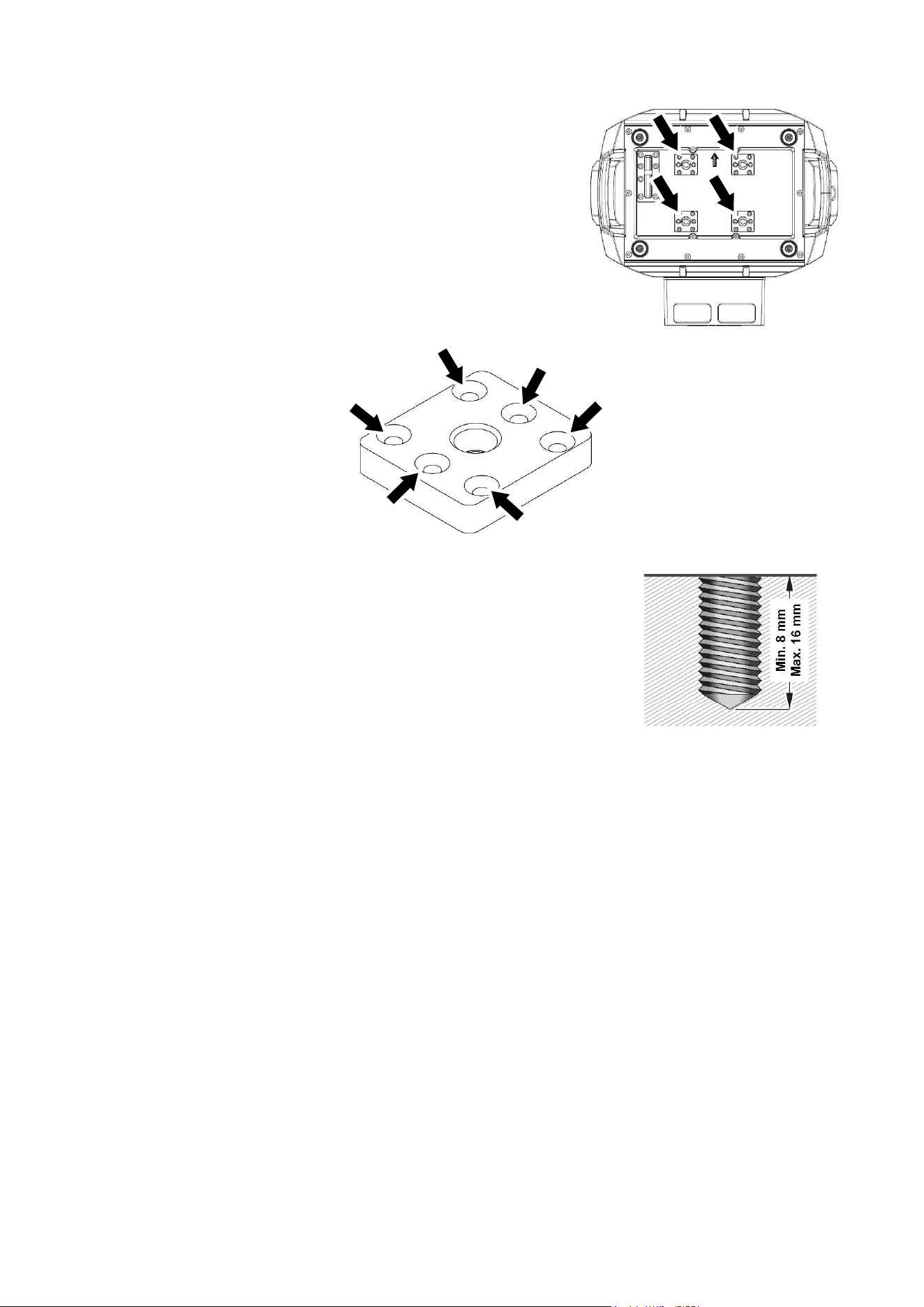
Martin
®
ERA 700 Performance IP Safety and Installation Manual Revision F 13
3. See illustration on right. Remove the six mounting screws from
each of the four quarter-turn fastener receptacle blocks
(arrowed) in the base of the fixture and remove the blocks from
the fixture. Keep the screws and the blocks for possible future
use.
4. See illustration below. Fasten the four M12 threaded blocks
from the M12 fastener blocks kit into the fixture base in place of
the quarter-turn fastener receptacle blocks that you have just
removed. Use the slightly longer mounting screws that are
supplied in the M12 mounting block kit, six screws per
mounting block, to fasten the M12 threaded blocks into the
base passing the screws (arrowed) through the six holes in the
mounting block.
5. To fasten the fixture to a surface or structure, obtain four M12 bolts
that are suitable for their purpose, including the weight that they will
support and the installation environment. Use high-strength stainless
steel in permanent outdoor installations. Use washers under bolt
heads. Use a thread locking compound where necessary for a safe
installation.
Warning! The bolts must be a suitable length. See illustration on right.
Check that each bolt will protrude minimum 8 mm (0.32 in.) and
maximum 16 mm (0.64 in.) into a fastener block in the base of the
fixture when all hardware is installed and the bolts are tightened.
6. Fasten the fixture into position using the four M12 bolts tightened into the mounting blocks and
installation hardware that is suitable for the weight supported and the installation environment.
Securing with a safety cable
1. Obtain a safety cable (or other secondary attachment) that is approved for the weight of the fixture.
2. Fasten the cable to the safety cable attachment point in the base of the fixture (see C in illustration
above) by either looping it around or fastening a carabiner clip to the attachment point C.
3. Remove as much slack as possible from the safety cable (by looping the cable around the truss chord,
for example) and fasten it to a secure anchoring point.
4. Make sure that the safety cable will hold the fixture if a primary attachment fails.
5. Make sure that there is no possibility of the head colliding with other fixtures or objects when it moves
through its full pan and tilt ranges,
14 Martin
®
ERA 700 Performance IP Safety and Installation Manual Revision F
AC mains power
Warning! Read ‘Safety information’ on page 4 before connecting the fixture to AC
mains power.
The fixture has an auto-ranging power supply that accepts AC mains power at 100-240 V at
50/60 Hz. Do not apply AC mains power at any other voltage or frequency to the fixture.
The fixture’s maximum current draw is as follows:
• At 100-120 V~: 11.1 A
• At 200-240 V~: 3.7 A
Typical half-cycle RMS inrush current: 14.0 A at 230 V, 50 Hz.
Typical earth-leakage current: 0.43 mA.
The fixture requires a power input cable with an IP65-rated Neutrik powerCON TRUE1 NAC3FX-W (TOP)
or equivalent female cable connector for AC mains power input. The cable must meet the requirements
listed under “Protection from electric shock” on page 5. Martin can supply suitable input cables with
connectors 1.5 m (4.9 ft.) or 5 m (16.4 ft.) long, as well as loose input connectors (see the Martin website
at www.martin.com).
The fixture can be hard-wired to a building electrical installation if you want to install it permanently.
Alternatively, you can connect it to local power outlets if you install a suitable power plug on the power
input cable. When installing a power plug, follow the plug manufacturer’s instructions and connect the
wires in the power cable following the color coding guide in the table below:
Live or L
Neutral or N
Earth, Ground or
US system
Black
White
Green
EU system
Brown
Blue
Yellow/green
If you need to install a Neutrik powerCON TRUE1 (TOP) or equivalent IP65-rated connector on a power
cable, follow the connector manufacturer’s instructions (normally published on the manufacturer’s website
or included with the product), respecting the color coding guide above.
Connecting to power
Connect the fixture to AC mains power by lining up the keys in the IP65 power input cable connector with
the keyways in the power input connector in the connections panel, inserting the connector and twisting
clockwise. Twist the cable connector counterclockwise and remove it from the connections panel to
disconnect.
The fixture does not have an on/off switch. It becomes active as soon as power is applied at the power
input connector. Be prepared for the head to move suddenly and for the fixture to emit bright light as soon
as power is applied.
Martin
®
ERA 700 Performance IP Safety and Installation Manual Revision F 15
Maintenance
Warning! Read ‘Safety information’ on page 4 before servicing the fixture.
Cleaning
Excessive dust, smoke fluid, and particle buildup degrades performance, causes overheating and will
damage the fixture. Damage caused by inadequate cleaning or maintenance is not covered by the product
warranty.
The cleaning of external optical lenses must be carried out periodically to optimize light output. Cleaning
schedules for lighting fixtures vary greatly depending on the operating environment. It is therefore
impossible to specify precise cleaning intervals for the fixture. Environmental factors that may result in a
need for frequent cleaning include:
• Use of smoke or fog machines.
• High airflow rates (near air conditioning vents, for example).
• Presence of cigarette smoke.
• Airborne dust (from stage effects, building structures and fittings or the natural environment at outdoor
events, for example).
If one or more of these factors is present, inspect fixtures within their first 100 hours of operation to see
whether cleaning is necessary. Check again at frequent intervals. This procedure will allow you to assess
cleaning requirements in your particular situation. If in doubt, consult your Martin dealer about a suitable
maintenance schedule.
Use gentle pressure only when cleaning, and work in a clean, well-lit area. Do not use any product that
contains solvents or abrasives, as these can cause surface damage.
To clean the fixture:
1. Disconnect the fixture from power and allow it to cool for at least 15 minutes.
2. Vacuum or gently blow away dust and loose particles from the outside of the fixture and the air vents
at the back and sides of the head and in the base with low-pressure compressed air. Holding cooling
fan blades stationary with a screwdriver will protect them from spinning too fast and possibly being
damaged when you apply a vacuum or air jet.
3. Clean surfaces by wiping gently with a soft, clean lint-free cloth moistened with a weak detergent
solution. Do not rub glass surfaces hard: lift particles off with a soft repeated press. Dry with a soft,
clean, lint-free cloth or low-pressure compressed air. Remove stuck particles with an unscented tissue
or cotton swab moistened with glass cleaner or distilled water.
4. Clean the pressure equalization valve on the back of the fixture by brushing gently with a soft brush. If
the valve appears to be blocked, contact a Martin Service agent for replacement.
5. Dry the fixture before putting it into storage.
Uploading new firmware
Important! Do not switch the fixture off or disconnect the source of the firmware during an update, or the
firmware will be corrupted.
You can check the currently installed firmware version in the INFORMATION menu. Firmware updates
can be downloaded automatically from the Martin cloud using the Martin Companion software suite on a
PC connected to the Internet.
Fixture information and settings are not affected when you upload new firmware to the fixture. All ERA 700
Performance IP fixtures that are powered on and connected via a DMX link to the fixture that you update
will also have their firmware updated.
If you update firmware to a newer version, check the ERA 700 Performance IP area of www.martin.com to
see whether an updated version of the fixture’s User Manual is available for the new firmware.

16 Martin
®
ERA 700 Performance IP Safety and Installation Manual Revision F
You need the following in order to install firmware:
• A Windows PC running the latest version of the Martin Companion software suite that is available for
download from the Martin website at www.martin.com.
• The latest ERA 700 Performance IP firmware files (Martin Companion automatically downloads these
from the Martin fixture firmware cloud when you run it on a PC that is connected to the Internet).
• A Martin Companion Cable USB-DMX hardware interface (available from your Martin supplier). Note
that you can install new firmware in multiple fixtures at the same time using the Martin Companion
Cable.
To install the ERA 700 Performance IP firmware using a Martin Companion Cable:
1. Apply power to the ERA 700 Performance IP fixture(s) and allow it to boot.
2. Connect the Martin Companion Cable’s USB connector to a USB port on your PC. Connect the Martin
Companion Cable’s XLR connector to either the fixture’s DMX IN connector or the DMX link.
3. Start the PC and launch Martin Companion. Check that the Martin Companion application correctly
detects the Martin Companion Cable (a green dot should appear next to USB Connected in the top
right-hand corner of the window).
4. Locate the latest ERA 700 Performance IP firmware in Martin Companion’s Firmware window.
5. Start the firmware update by clicking Update Firmware in Martin Companion. Do not disconnect the
Martin Companion Cable or power off the fixture(s) until the upload is complete and the fixture(s) has
successfully rebooted.
6. If you are updating multiple fixtures over a DMX link, check that they have all rebooted correctly.
Service and repairs
There are no user-serviceable parts inside the fixture. Do not open the housing. The LED light source is
not user-replaceable.
Refer any service or repair operation not described in this manual to an authorized Martin service
technician. Do not try to carry out such an operation yourself, as doing so may present a health or safety
risk. It may also cause damage or malfunction, and it may void your product warranty.
Installation, on-site service and maintenance can be provided worldwide by the Martin Professional Global
Service organization and its approved agents, giving owners access to Martin’s expertise and product
knowledge in a partnership that will ensure the highest level of performance throughout the product’s
lifetime. Please contact your Martin supplier for details.
Martin
®
ERA 700 Performance IP Safety and Installation Manual Revision F 17
Specifications
For full product specifications, see the ERA 700 Performance IP area of the Martin website at
www.martin.com
FCC Compliance
This equipment has been tested and found to comply with the limits for a Class B digital device, pursuant
to part 15 of the FCC Rules. These limits are designed to provide reasonable protection against harmful
interference in a residential installation. This equipment generates, uses and can radiate radio frequency
energy and, if not installed and used in accordance with the instructions, may cause harmful interference
to radio communications. However, there is no guarantee that interference will not occur in a particular
installation. If this equipment does cause harmful interference to radio or television reception, which can
be determined by turning the equipment off and on, the user is encouraged to try to correct the
interference by one or more of the following measures:
• Reorient or relocate the receiving antenna.
• Increase the separation between the equipment and receiver.
• Connect the equipment into an outlet on a circuit different from that to which the receiver is connected.
• Consult the dealer or an experienced radio/TV technician for help.
FCC Supplier’s Declaration of Conformity
This device complies with part 15 of the FCC Rules. Operation is subject to the following two conditions:
1. This device may not cause harmful interference, and
2. this device must accept any interference received, including interference that may cause undesired
operation.
Canadian Interference-Causing Equipment Regulations – Règlement sur le Matériel Brouilleur du
Canada
This Class B digital apparatus meets all requirements of the Canadian Interference-Causing Equipment
Regulations.Cet appareil numérique de la classe B respecte toutes les exigences du Règlement sur le
Matériel Brouilleur du Canada.
CAN ICES-003 / NMB-005
EU Declaration of Conformity
An EU Declaration of Conformity covering this product is available for download from the ERA 700
Performance IP product area of the Martin website at www.martin.com.
Disposing of the product
Martin products are supplied in compliance with Directive 2012/19/EC of the European
Parliament and of the Council of the European Union on WEEE (Waste Electrical and
Electronic Equipment), where applicable.
Help preserve the environment! Ensure that this product is recycled at the end of its life.
Your supplier can give details of local arrangements for the disposal of Martin products


www.martin.com
