1
Serial Number
SG24112
Purchase Date
ITEM #5974899
MODEL #KPW 4280-06
Dual-Port Portable
Pressure Washer
Español p. 22
ATTACH YOUR RECEIPT HERE
Thank you for purchasing this KOBALT product.
Questions, problems or missing parts?
Before returning, contact us on:
888-356-2258, 8 a.m. - 8 p.m., EST, Monday - Sunday or [email protected].
KOBALT and logo design are trademarks or registered
trademarks of LF, LLC. All rights reserved.

2
TABLE OF CONTENTS
PRODUCT SPECIFICATIONS
Product Specications............................................................................................................................
Package Contents..................................................................................................................................
Hardware Contents.................................................................................................................................
Symbols..................................................................................................................................................
Safety Information..................................................................................................................................
Preparation.............................................................................................................................................
Assembly Instructions............................................................................................................................
Operating Instructions............................................................................................................................
Care and Maintenance .........................................................................................................................
Transportation and Storage...................................................................................................................
Troubleshooting.....................................................................................................................................
Warranty................................................................................................................................................
Replacement Parts List.........................................................................................................................
2
3
4
5
6
7
8
14
16
18
19
20
21
SPECIFICATIONS
Brushless Motor
80 V Lithium-ion
Max. Pounds Per Square Inch Pressure 3000 PSI
Rated Gallons Per Minute 1.1 GPM
Max. Rated Gallons Per Minute 2.0 GPM
Max. Pounds Per Square in ECO Mode 2200 PSI
Maximum Inlet Water Temperature 104 °F (40 °C)
3
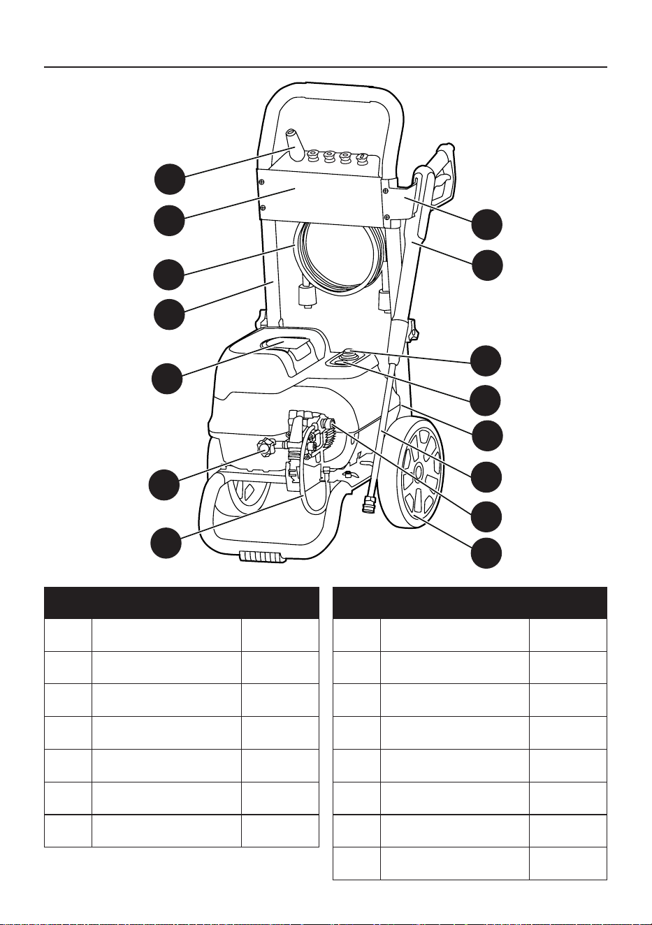
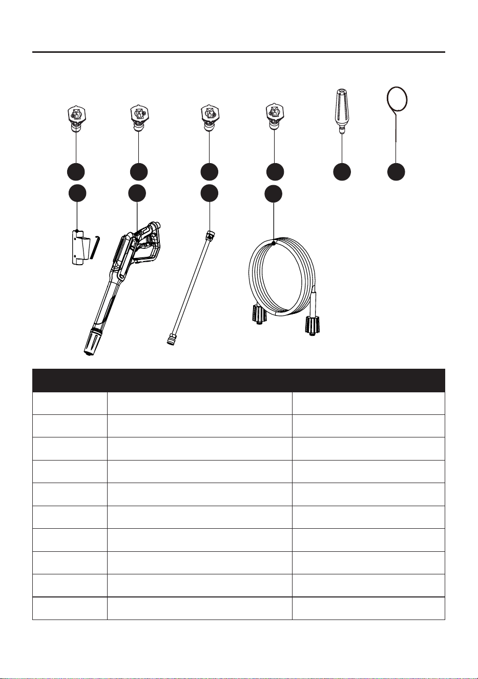
PACKAGE CONTENTS
PART DESCRIPTION QUANTITY
A Spray gun holder
1
B Spray gun
1
C Button
1
D ECO membrane button
1
E
Lower handle
1
F
Spray wand
1
G Water outlet
1
PART DESCRIPTION QUANTITY
H Wheel
2
I Detergent hose
1
J Water inlet
1
K Battery lid
1
L Upper handle
1
M
High pressure hose
1
N
Front panel
1
O Nozzle
1
A
B
C
D
E
F
G
H
I
J
K
L
M
N
O

4
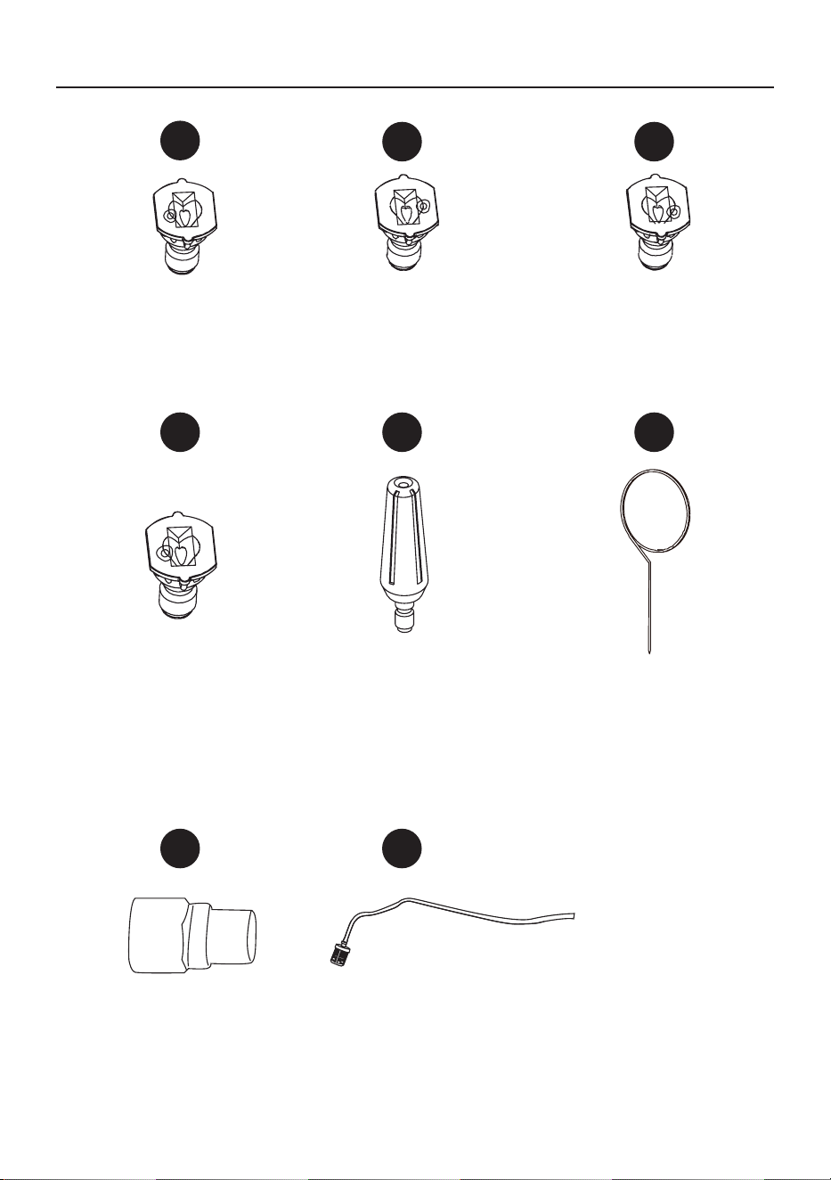
HARDWARE CONTENTS (not to scale)
Nozzle
Qty. 1
Nozzle
Qty. 1
AA
BB CC
DD EE
Nozzle
Qty. 1
Nozzle
Qty. 1
Turbo Nozzle
Qty. 1
FF
Spray Tip
Cleaning Tool
Qty. 1
GG HH
Air Release
Valve
Qty. 1
Self-siphon
Hose
Qty. 1
5
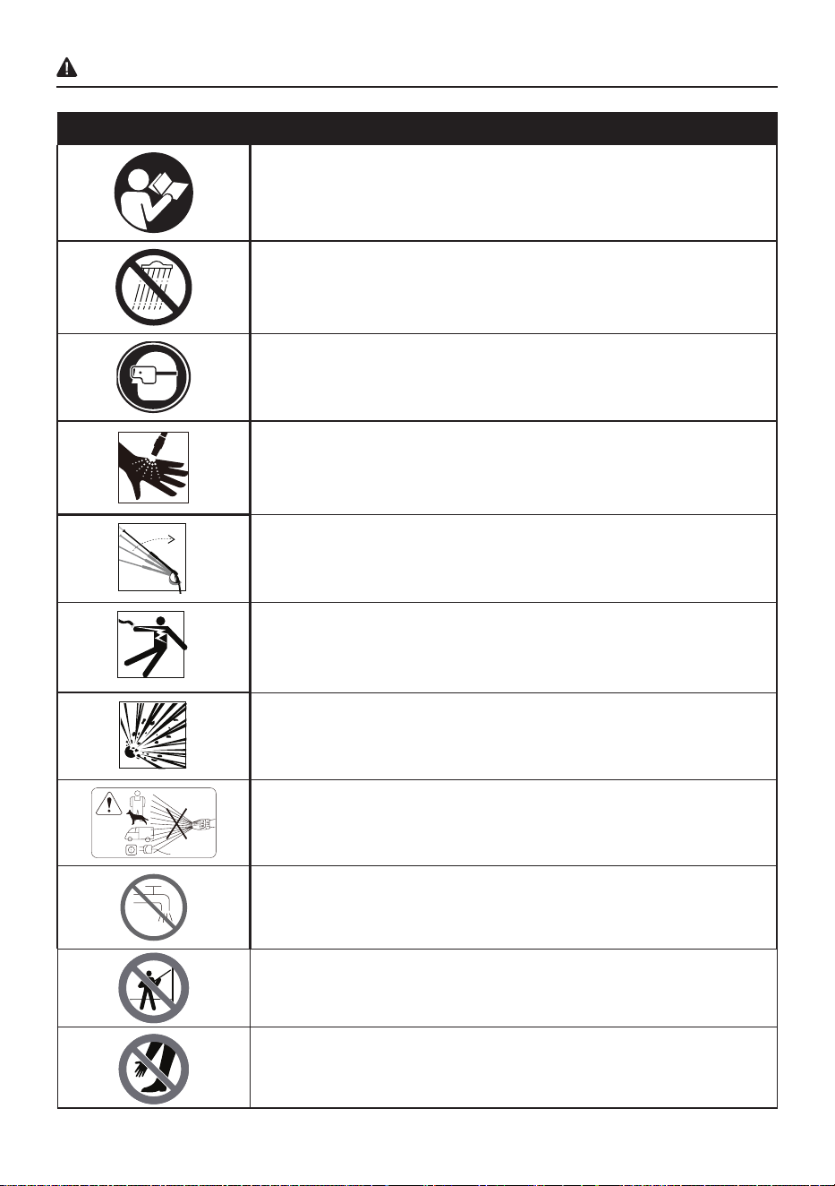
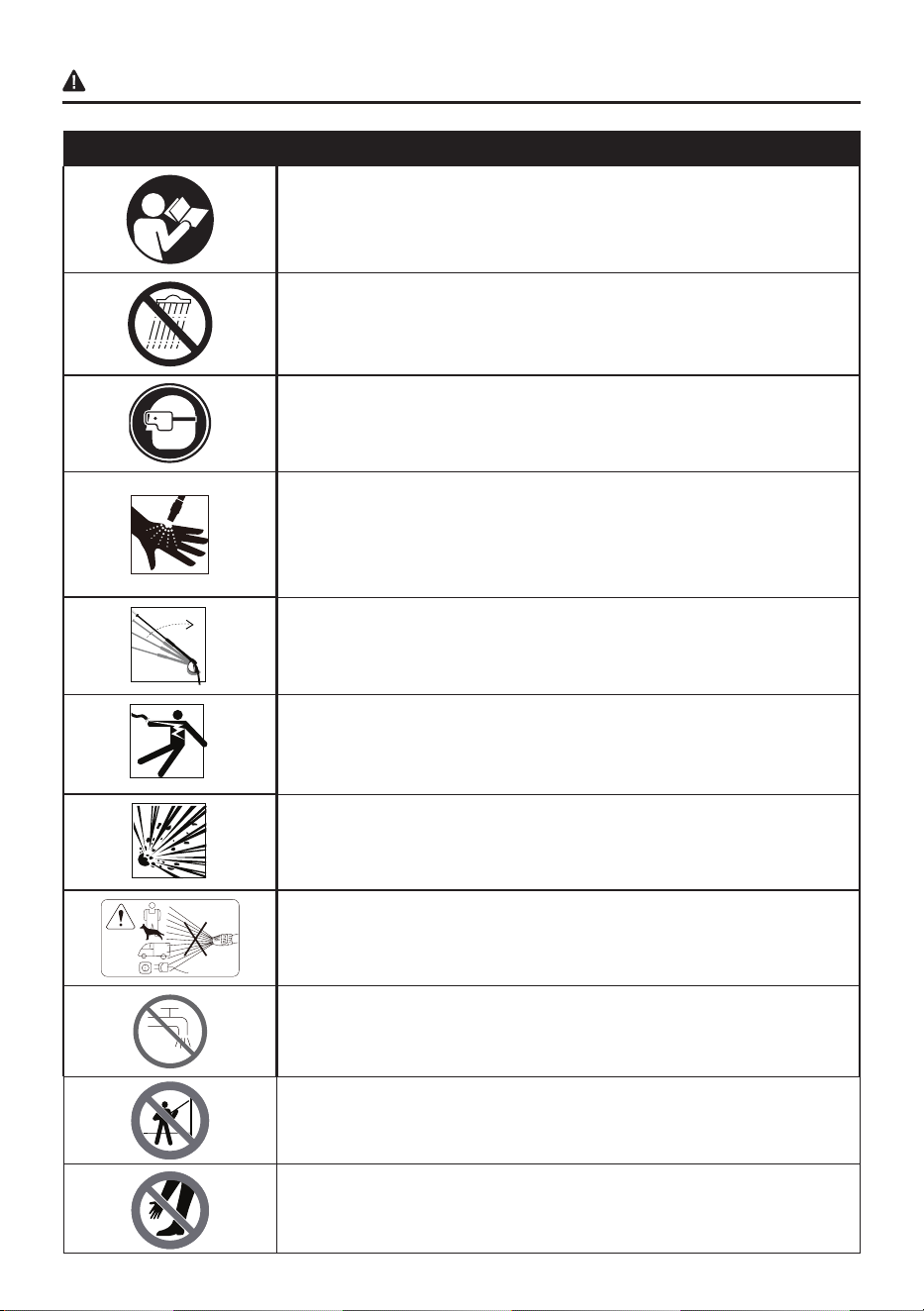
SYMBOLS EXPLANATION
Carefully read and understand instructions before operating the product
and follow all warnings and safety instructions.
Do not expose the product to rain or moist conditions.
Always wear safety goggles or safety glasses with side shields and, as
necessary, a full-face shield when operating this product.
To reduce the risk of high-pressure injection or injury, never direct a water
stream towards people or pets or place any body part in the stream.
Leaking hoses and ttings can also cause injury. Do not place hands near
high-pressure stream.
To reduce the risk of injury from kickback, hold the spray gun securely
with both hands when the product is on.
Failure to operate in dry conditions and neglecting safe practices can
increase risk of electric shock.
Burst hazard.
Warning! Never aim the spray gun at humans, animals, the product,
power supply, or any electrical products.
The product is not suitable for connection to the drinking water mains
without backow preventer.
Only set product on at, horizontal surfaces. Never lift product during
operation.
Keep hands and feet away from the cleaning area while the product is
running.
SYMBOLS
6
The following signal words and meanings are intended to explain the levels of risk associated with this
product.
SYMBOL SIGNAL MEANING
DANGER
Indicates an imminently hazardous situation, which, if not
avoided, will result in death or serious injury.
WARNING
Indicates a potentially hazardous situation, which, if not avoided,
could result in death or serious injury.
CAUTION
Indicates a potentially hazardous situation, which, if not avoided,
may result in minor or moderate injury.
CAUTION
(Without Safety Alert Symbol) Indicates a situation that may
result in property damage.
SAFETY INFORMATION
Please read and understand this entire manual before attempting to assemble, operate or install the
product.
WARNING
Read all safety warnings and instructions. Failure to follow the warnings and instructions may result in
electric shock, re and/or serious injury.
• Read all the instructions before using the product.
• To reduce the risk of injury, close supervision is necessary when a product is used near children.
• Know how to stop the product and bleed pressures quickly. Be thoroughly familiar with the
controls.
• Stay alert – watch what you are doing.
• Do not operate the product when fatigued or under the inuence of alcohol or drugs.
• Keep operating area clear of all persons.
• Do not overreach or stand on unstable support. Keep good footing and balance at all times.
• Follow the maintenance instructions specied in the manual.
• For a Type 2 cleaning machine: WARNING – Risk of Injection or Injury– Do Not Direct Discharge
Stream At Persons.
• Prevent unintentional starting. Ensure the switch is in the o-position before connecting to battery
pack, picking up or carrying the product. Carrying the product with your nger on the switch or
energizing product that have the switch on invites accidents.
• Disconnect the battery pack from the product before making any adjustments, changing
accessories, or storing product. Such preventive safety measures reduce the risk of starting the
product accidentally.
• Recharge only with the KDC 50-06 charger specied by the manufacturer. A charger that is
suitable for one type of battery pack may create a risk of re when used with another battery
pack.
• Use products only with specically designated KB 480-06 battery packs. Use of any other battery
packs may create a risk of injury and re.
• When KB 480-06 battery pack is not in use, keep it away from other metal objects, like paper
clips, coins, keys, nails, screws or other small metal objects, that can make a connection from
one terminal to another. Shorting the battery terminals together may cause burns or a re.
• Under abusive conditions, liquid may be ejected from the battery; avoid contact. If contact
accidentally occurs, ush with water. If liquid contacts eyes, additionally seek medical help.
SYMBOLS
7
SAFETY INFORMATION
• Liquid ejected from the battery may cause irritation or burns. (This advice is considered correct
for conventional NiMh, NiCd, lead acid and lithium-ion cell types. If this advice is incorrect for a
cell design that diers from these, then the correct advice may be substituted.)
• Do not use a battery pack or product that is damaged or modied. Damaged or modied batteries
may exhibit unpredictable behavior resulting in re explosion or risk of injury.
• Do not expose a battery pack or product to re or excessive temperature. Exposure to re or
temperature above 130°C (265°F) may cause re explosion.
• Follow all charging instructions and do not charge the battery pack or product outside of the
temperature range specied in the instructions. Charging improperly or at temperatures outside of
the specied range may damage the battery and increase the risk of re.
• Have servicing performed by a qualied repair person using only identical replacement parts. This
will ensure that the safety of the product is maintained.
• Do not modify or attempt to repair the product or the battery pack (as applicable) except as
indicated in the instructions for use and care.
THE RECOMMENDED AMBIENT TEMPERATURE RANGE:
ITEM TEMPERATURE
Product storage 32˚F – 104˚F (0˚C – 40˚C)
Product operation 32˚F – 104˚F (0˚C – 40˚C)
Battery charging 39˚F – 104˚F (4˚C – 40˚C)
Charger operation 32˚F – 104˚F (0˚C – 40˚C)
Battery storage 32˚F – 104˚F (0˚C – 40˚C)
Battery discharging 32˚F – 113˚F (0˚C – 45˚C)
WARNING(PROPOSITION 65)
Some dust created by power sanding, sawing, grinding, drilling, and other construction activities contains
chemicals known to cause cancer, birth defects or other reproductive harm. Some examples of these
chemicals are:
• Lead from lead-based paints;
• Crystalline silica from bricks and cement and other masonry products;
• Arsenic and chromium from chemically treated lumber.
Your risk of exposure to these chemicals varies depending on how often you do this type of work. To
reduce your exposure to these chemicals, work in a well-ventilated area, and work with approved safety
equipment, such as dust masks that are specially designed to lter out microscopic particles.
PREPARATION
Before beginning assembly of product, make sure all parts are present. Compare parts with package
contents list and hardware contents list. If any part is missing or damaged, do not attempt to assemble
the product.
Estimated Assembly Time: 5 minutes
Tools Required for Assembly (not included): Phillips Screwdriver
8
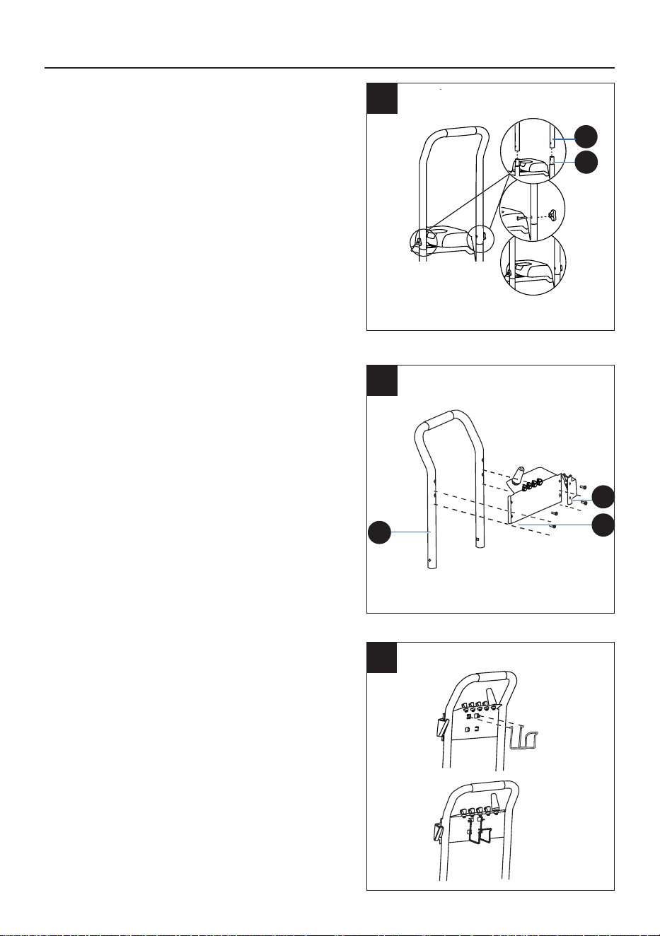
ASSEMBLY INSTRUCTIONS
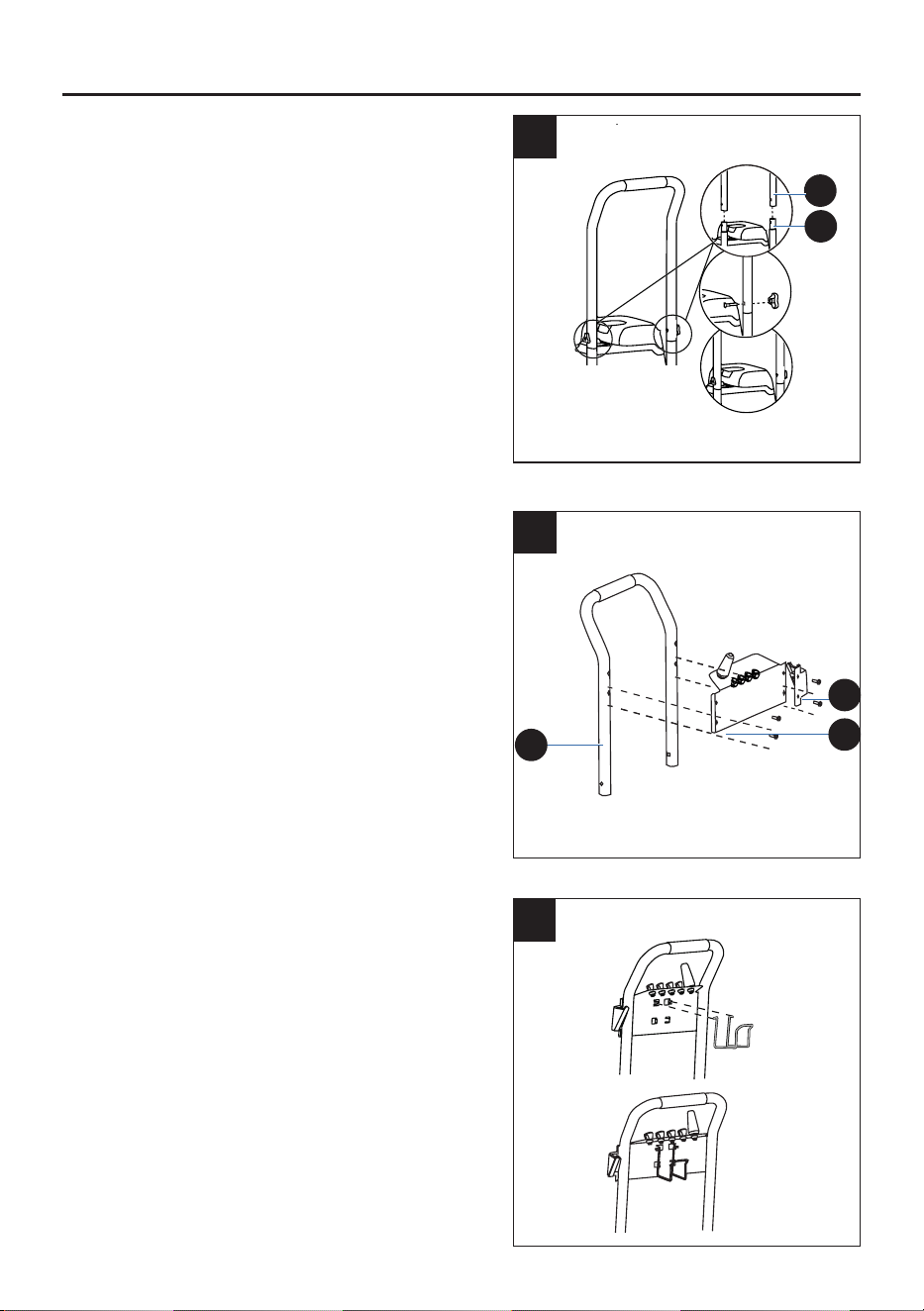
1
1. Installing the upper handle
• Align the holes on the upper handle (L) and
the lower handle (E).
• Insert the handle bolts and use the handle
knobs to tighten them.
L
2
2. Installing the upper panel and spray gun
holder
• Align the screw sleeves of the front panel (N)
and spray gun holder (A) with the screw holes
on the upper handle (L).
• Tighten them with a Phillips screwdriver (not
included).
E
A
N
L
3
3. Installing the hose hook
• Push the hose hook ends into the clips behind
the upper panel tightly.
9
ASSEMBLY INSTRUCTIONS
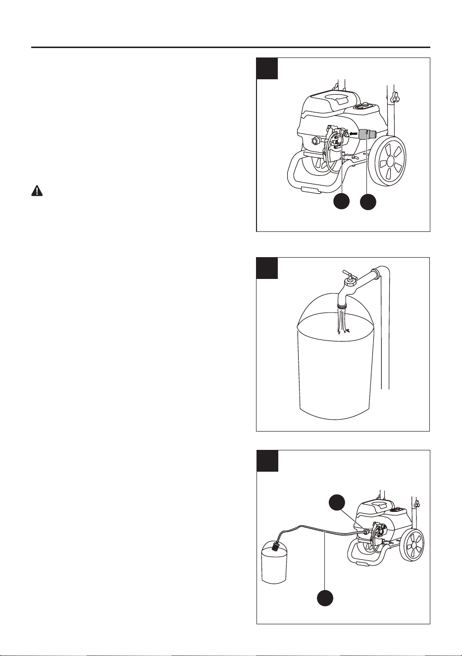
4
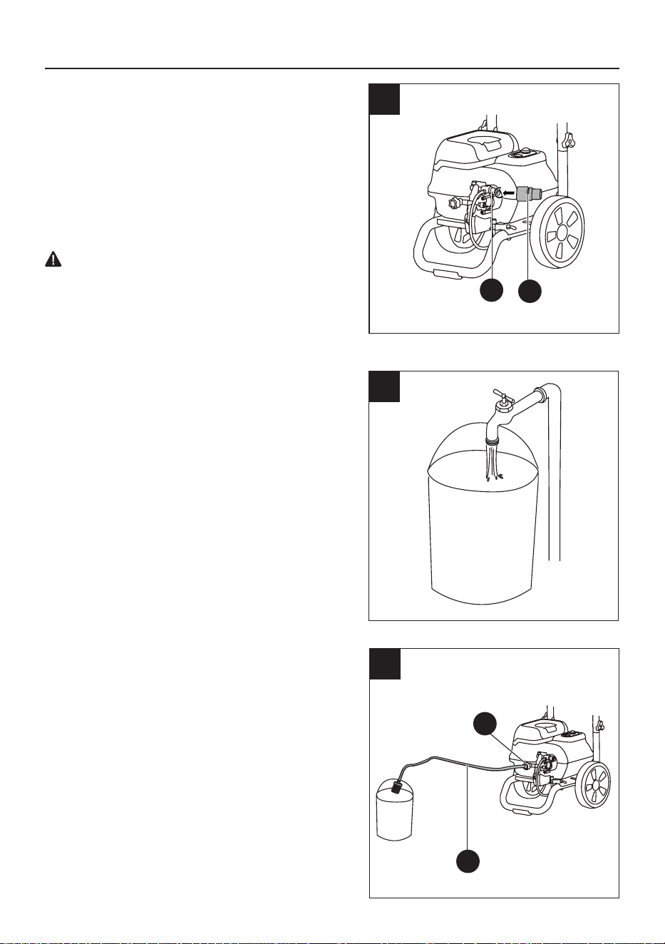
4. Installing the air release valve
NOTE: Use air release valve when using siphon
tube.
• Before installing the included high pressure
hose, place the air release valve (GG) onto
the pressure water outlet (G) and rotate clock-
wise until tightened.
• Or directly connect the high pressure hose
to the water outlet (G), when not using the
siphon hose.
WARNING
Water exiting the air release valve (GG) is normal.
This valve bleeds air from the pump and will en-
able the siphon function.
5a
G
5a. Installing the self-siphon hose
NOTE: The pressure washer can absorb water
from water buckets, containers, and approved
stagnant bodies of water.
NOTE: Exhaust the siphon hose for 30 seconds
before installing the spray tip when using the
siphon function.
• Add water to the bucket.
5b
J
5b. Installing the self-siphon hose
• Insert one end of the self-siphon hose into
the water inlet (J). And put the other end of
the self-siphon hose (HH) into the bucket (not
included).
NOTE: When you use the self-siphon hose, you
should do the below instructions:
• The vertical height of the self-siphon hose
(HH) cannot exceed 4-ft.
• The internal self-siphon hose size is 0.03 ft -
0.04 ft (10 mm - 12 mm).
• A lter should be installed at the end of the
self-siphon hose (HH) into the bucket.
GG
HH
10
ASSEMBLY INSTRUCTIONS
6
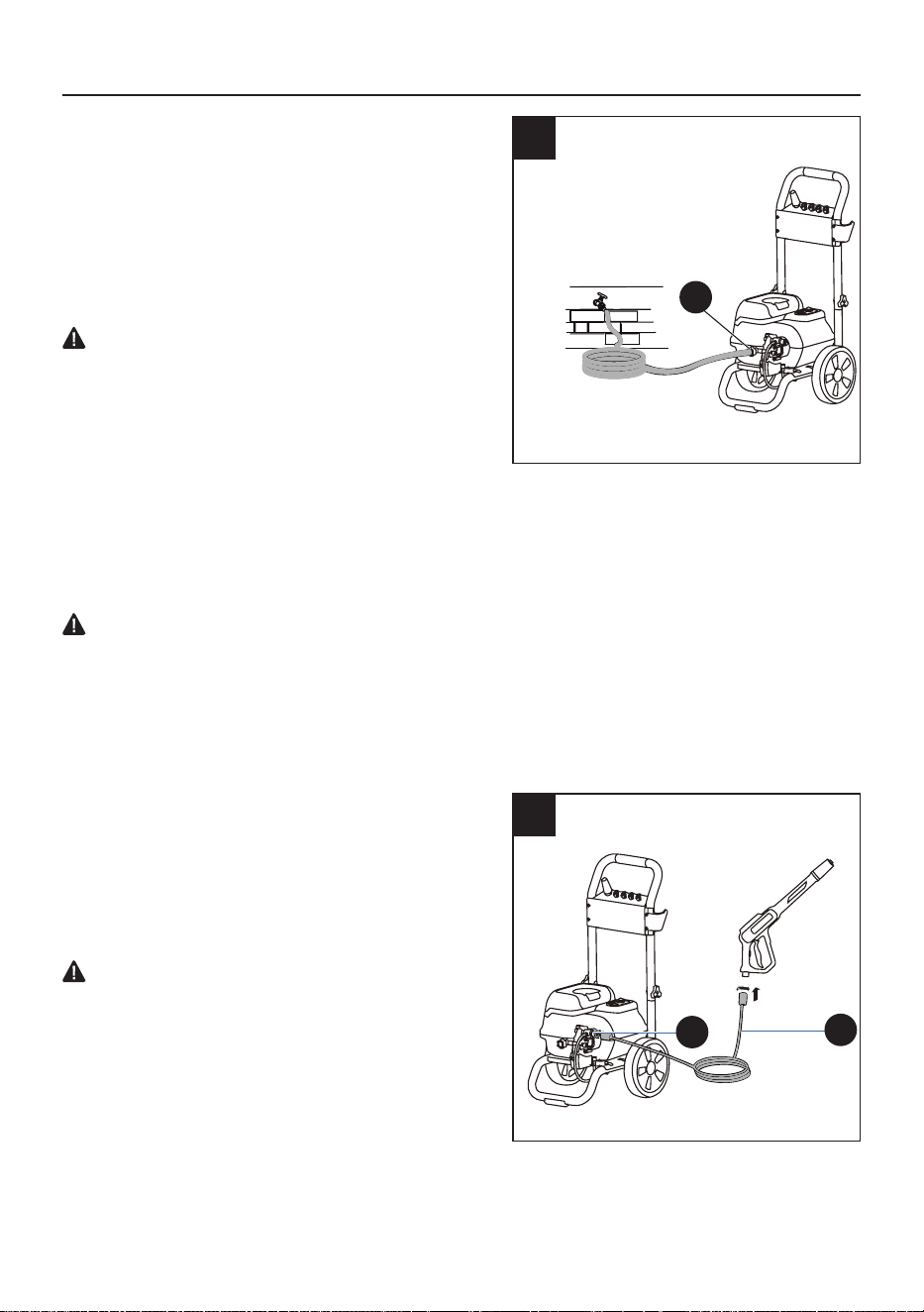
6. Connecting the water supply to the product
• Uncoil the garden hose.
• Let the water ow through the garden hose
for 30 seconds to clean out any debris.
• Turn the water supply o.
• Install and tighten the end of the garden hose
to the water inlet (J) connector.
NOTE: For easy operation, please use a
self-coiling garden hose (not provided).
WARNING
When you operate the self-coiling hose, make sure
that the hose has no blockage.
• The water supply must come from the water
main.
• Do not use hot water.
• Do not use water from ponds or lakes.
• Always observe all the local regulations
when you connect the garden hose to the
water supply. Direct connection through a
receiver tank or backow preventer is usually
permitted.
CAUTION
Inspect the lter in the water inlet connector before
you connect the garden hose.
• If the lter is damaged, do not use the product
until the lter is replaced.
• If the lter is dirty, clean the lter.
7
J
M
G
7. Installing the high pressure hose
• Push and turn counterclockwise one end
of the high pressure hose (M) into the inlet
coupler.
• Install and tighten the other end of the high
pressure hose onto the water outlet (G)
coupler.
CAUTION
There must be a minimum of 10 feet of free hose
between the water inlet and the water supply.
11
ASSEMBLY INSTRUCTIONS
8
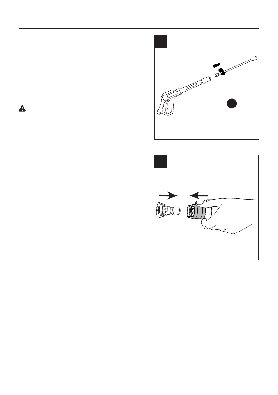
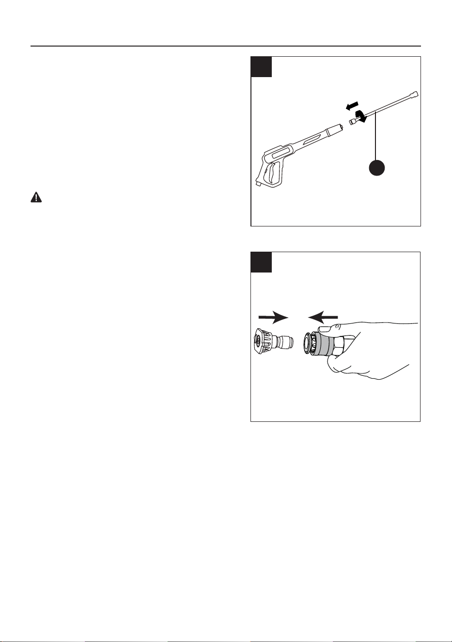
8. Installing the spray wand
• Push the end of the spray wand (F) into the
trigger handle and rotate clockwise to secure.
• Pull on the spray wand (F) to be certain it is
properly secured.
NOTE: Before installing the spray wand, you
should turn on the water, and then push the trigger
safety lock-out up on the gun and squeeze the
trigger to purge pump system of air and impurities.
WARNING
Make sure that the connection has no leakage.
9
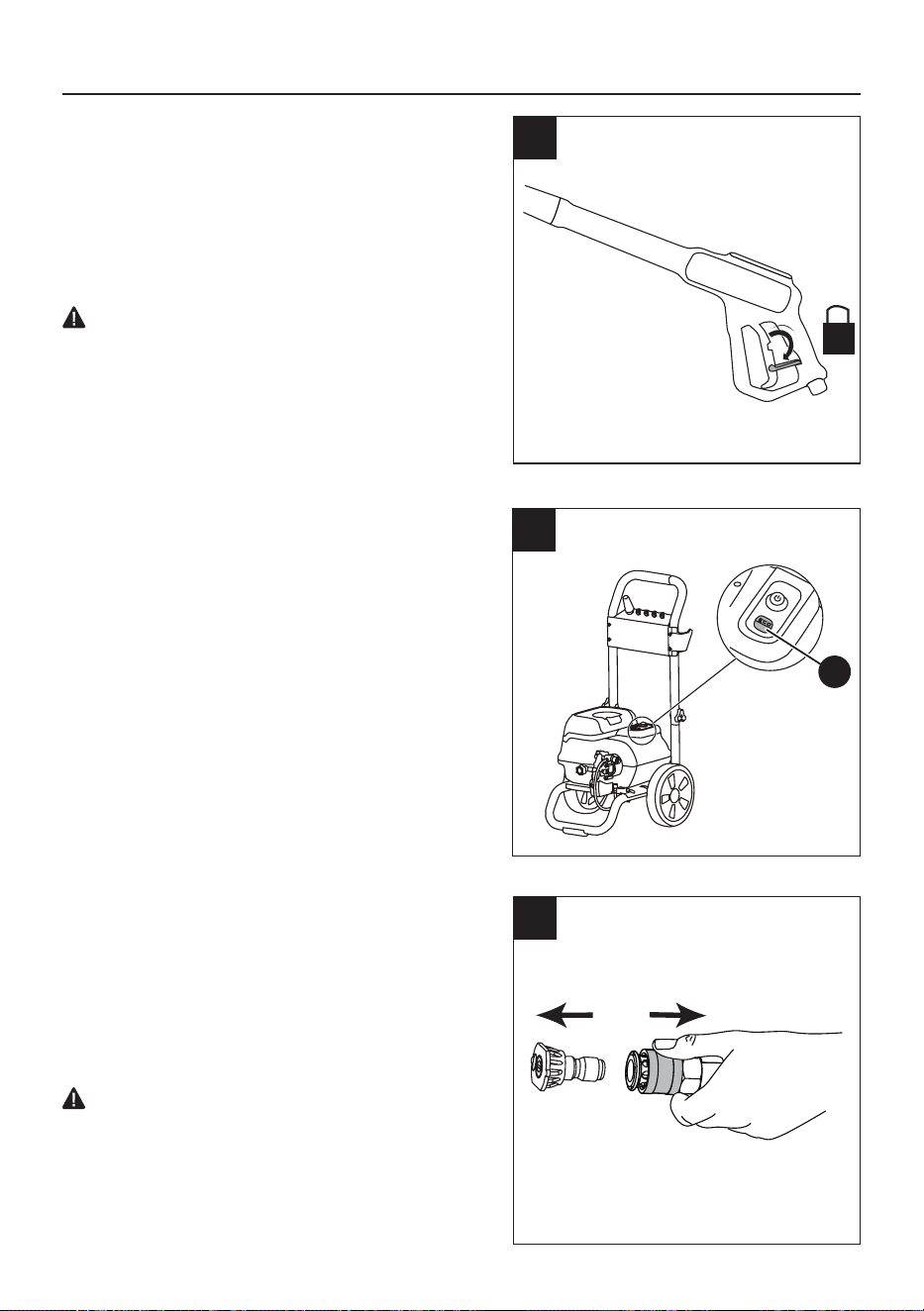
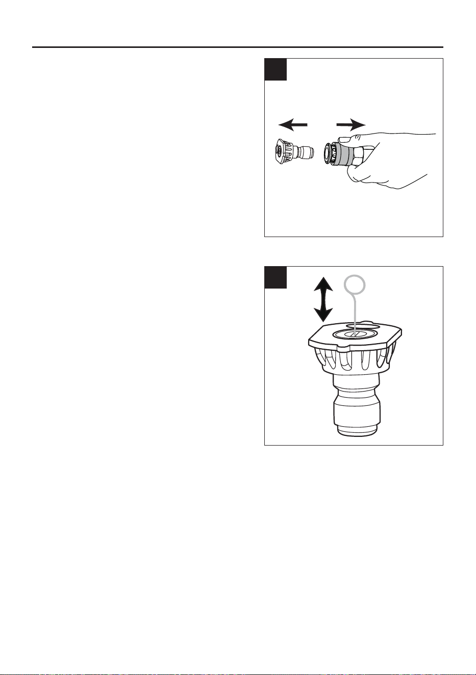
9. Installing the spray tip
• Pull back and hold the quick-connect collar on
the spray wand.
• Insert the desired spray tip.
• Release the quick-connect collar to lock the
spray tip in place.
NOTE: Tug on the spray tip to make sure it is
secured in place.
①
②
F
12
ASSEMBLY INSTRUCTIONS
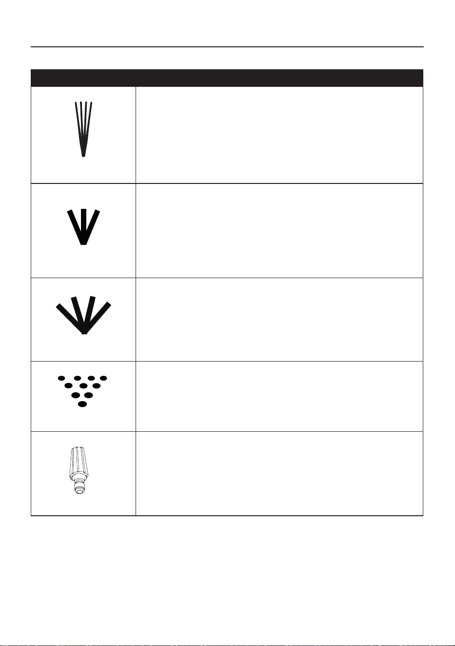
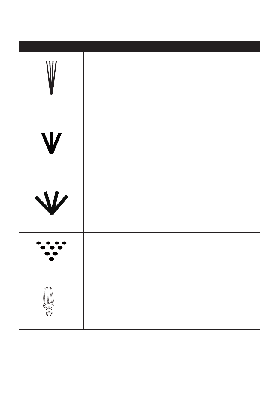
NOZZLE TYPE
NOZZLE APPLICATION
Yellow - Narrow fan tip (15°)
The Yellow pressure washer tip provides the most pressure with its
15-degree angle tip. It provides adequate pressure to remove dirt from
surfaces, typically used for surface preparation such as removing dirt,
mildew or paint, and can be used for a wide variety of cleaning appli-
cations. The small angle causes high pressure which needs to be used
carefully.
25
O
Green - Narrow fan tip (25°)
The green pressure washer tip provides high versatility with its 25
degree angle tip. Referred to as the washing tip because it provides
adequate pressure to remove dirt from surfaces, but is designed to
not damage many surfaces. This pressure washer tip is designed for
“sweeping” foliage or debris given its wide angle. This tip is versatile due
to its wide area of cleaning and strong pressure application.
40
O
White - Wide fan tip (40°)
The white 40 degree tip, referred to as the “fan” tip, creates the widest
area of cleaning with relatively low pressure. This pressure washer tip is
best used for light or delicate cleaning applications. It is recommended
for light cleaning on wood decks and other soft or delicate surfaces.
SO
AP
Black - Soap spray tip
The black soap spray tip is used for soap application. Soap is applied
under low pressure high volume for optimum performance. Soap cannot
be applied under high pressure with this product.
TURBO
Turbo Nozzle Tip
This nozzle rotates in a zero to 15 degree circular motion spray pattern
to break down tough dirt and grime. The spray pattern can cover area of
4 to 8 inches wide, depending on the distance between the tip and the
surface being cleaned.
15°
13
ASSEMBLY INSTRUCTIONS
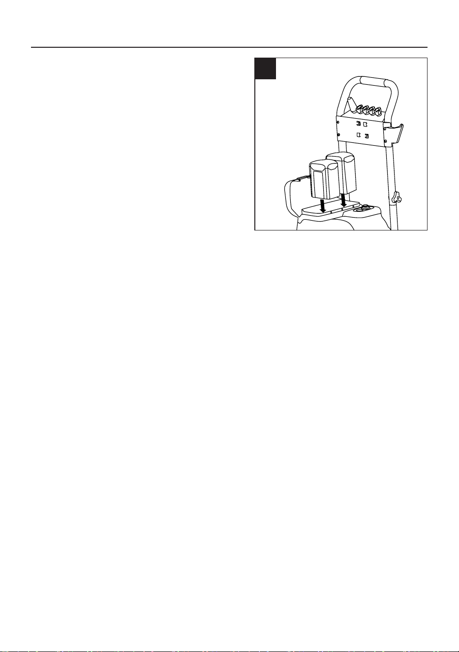
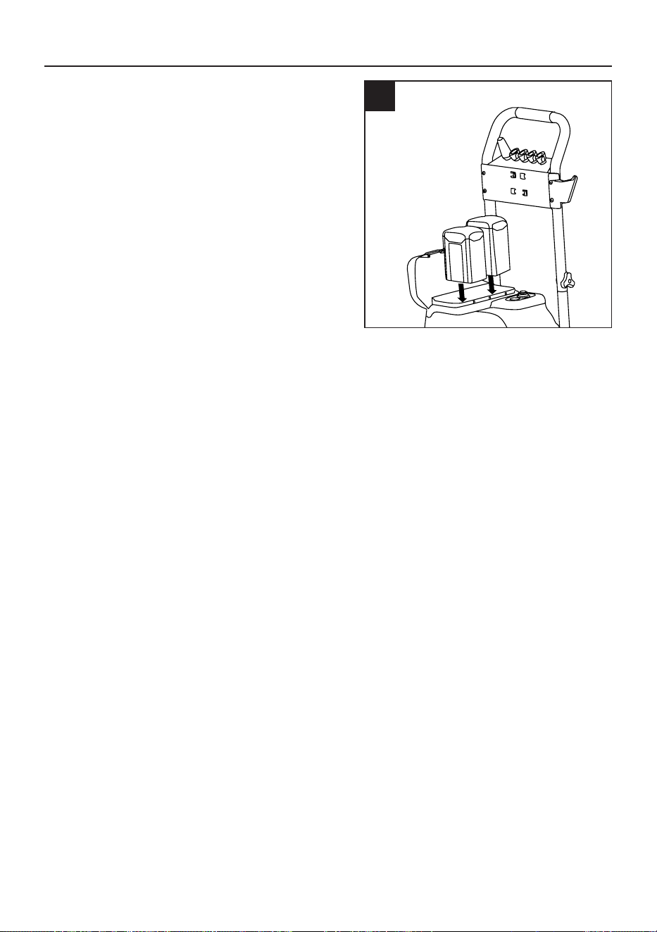
10
10. Installing the battery pack
NOTE: If the battery pack or charger is damaged,
replace the battery pack or the charger.
NOTE: Stop the product and wait until the engine
stops before you install or remove the battery pack.
NOTE: Read, know, and follow the instructions in
the battery and charger manual.
• Open the battery lid.
• Align the ribs on the battery packs with the
grooves in the battery compartment.
• Push the battery packs into the battery
compartment until the batter packs lock into
place.
• When you hear a click, the battery packs are
installed.
• Close the battery lid.
NOTE: You can insert one battery or two batteries
to start the product.
14
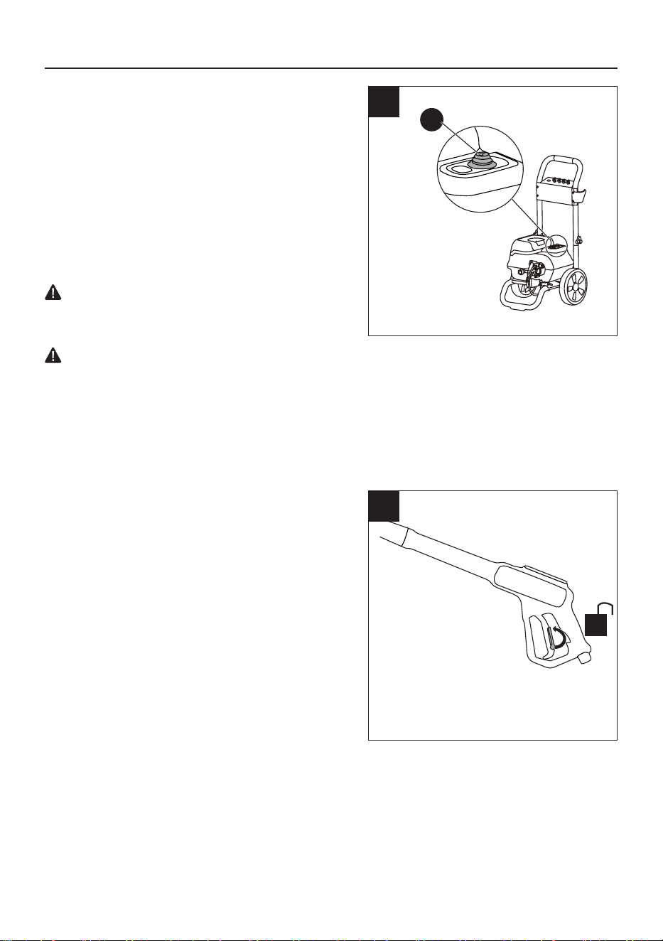
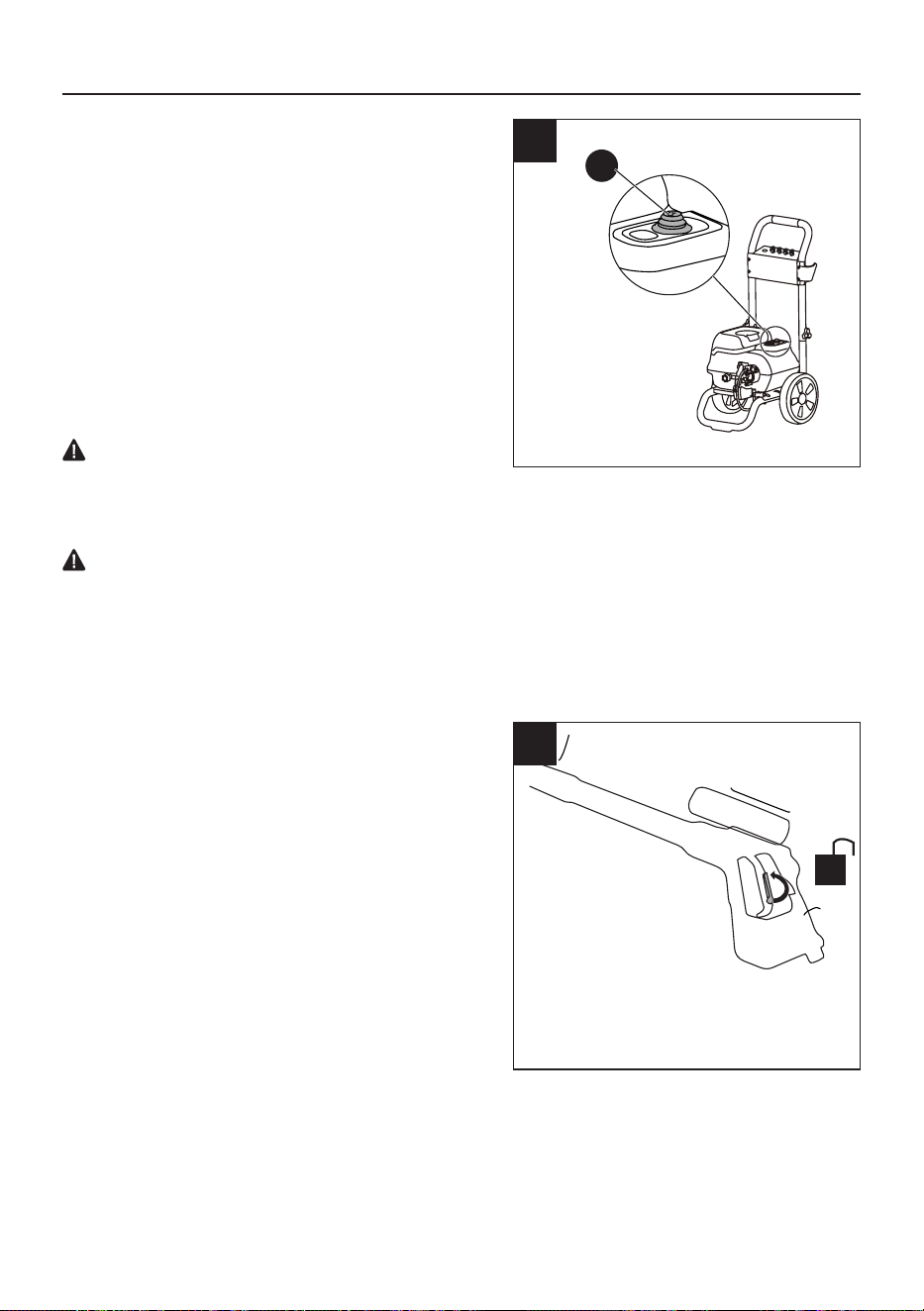
OPERATING INSTRUCTIONS
1
C
1. Starting the product
Before you start the product:
• Turn the water supply on.
• Pull the spray gun trigger to release air
pressure.
• If a stable stream of water comes into view,
release the spray gun trigger.
• Install battery pack as previously described.
• Press the button (C) once to start the product.
• Turn the water supply on.
• Pull the spray gun trigger.
WARNING
Make sure that all the connections are tight and
have no leakage before operation.
CAUTION
Do not operate without the water supply
connected.
Water exiting the water outlet as the pressure
washer primes is normal. This is needed to bleed
the air from the system.
2a. Using the spray gun
To start:
• Push the spray gun trigger safety lock-out up
and into its original position.
• Pull and hold the spray gun trigger to start the
product.
2a

15
OPERATING INSTRUCTIONS
2b
2b. Using the spray gun
To stop:
• Release the spray gun trigger to stop water
ow through the spray tip.
• Push the spray gun trigger safety lock-out
down until it clicks into the slot.
WARNING
For safe control, keep your hands on the spray gun
at all times.
3. Energy saving function
• The ECO membrane button (D) is an energy
saving button for the pressure washer. This
button will help to increase usage time by
reducing power.
3
4
4. Changing the spray tip
Before you change the spray tip:
• Pull the spray gun trigger to release water
pressure.
• Engage the trigger safety lock-out on the
spray gun.
• Stop the product.
• Change the spray tip.
WARNING
Do not point the spray wand at your face or others'
faces.
D
16
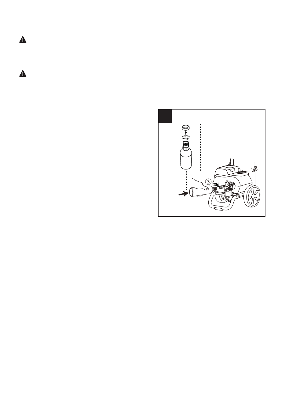
CARE AND MAINTENANCE
WARNING
Before maintenance, make sure that you
• Stop the product.
• Wait until all the moving parts stop.
WARNING
Do not let brake uids, gasoline, petroleum-based materials touch the plastic parts. Chemicals can
cause damage to the plastic, and make the plastic unserviceable.
1. Using pump protector
• Regular use of pump protector (not included)
can prolong the life of the product:
• Removing hard water mineral deposits.
• Lubricating pump seals and pistons.
• Preventing freeze damage.
• To maintain the best performance from the
product, pump protector should be added to
the product after every use and before long
term storage.
NOTE: The following steps are typical for adding
pump protector to the product. Always read the
specic instructions provided by the manufacturer
of the pump protector used before starting.
• Turn the water tap o and set the ON/OFF
switch to OFF.
• Press the trigger for approximately 1 minute
or until no more water escapes from the
connected accessory.
• Remove the batteries from the battery
compartment.
• Turn the water tap o and set the ON/OFF
switch to OFF.
• Press the trigger for approximately 1 minute
or until no more water escapes from the
connected accessory.
• Remove the batteries from the battery
compartment.
1
①
②
17
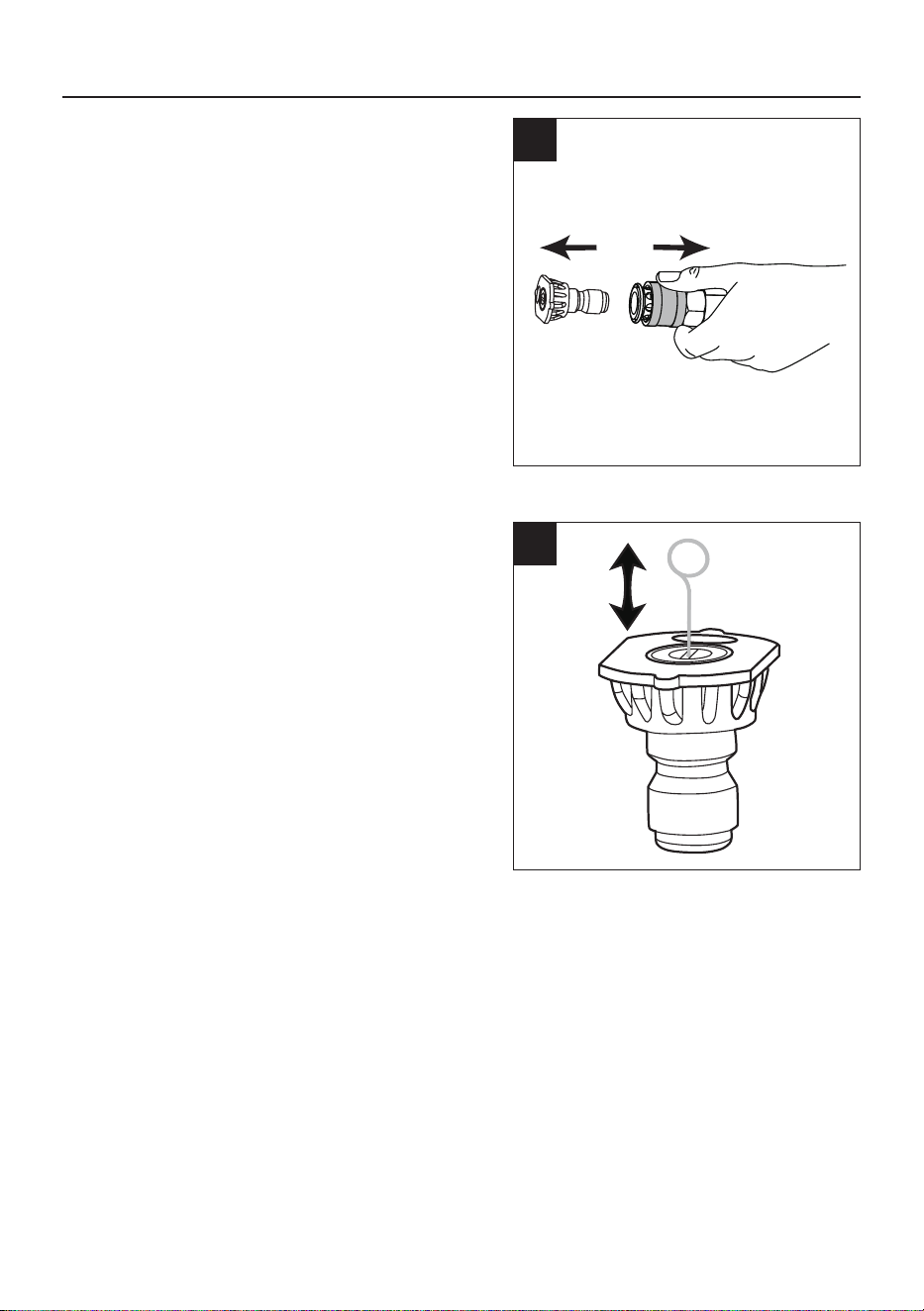
CARE AND MAINTENANCE
2a
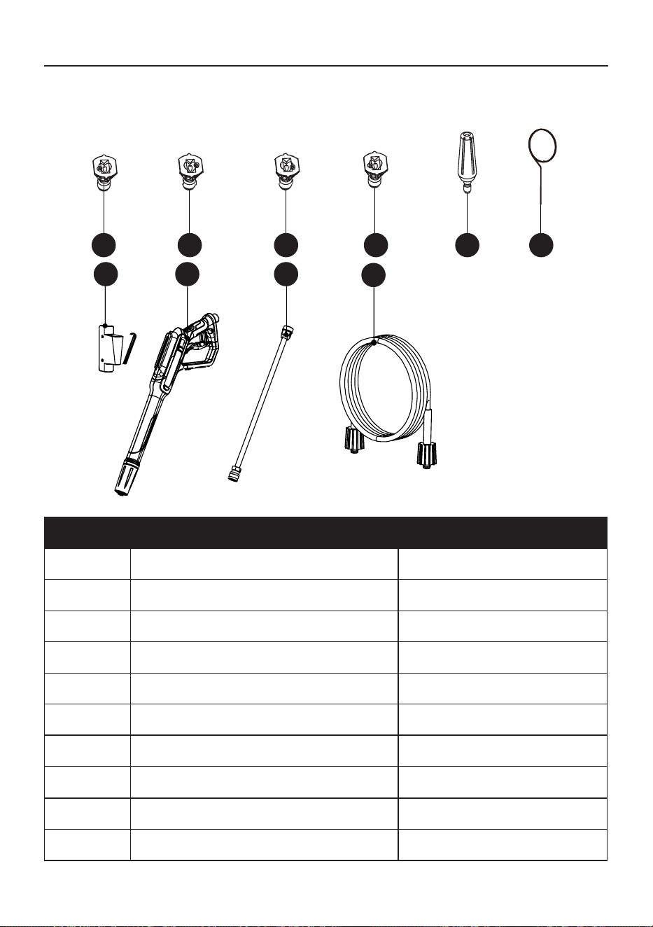
2a. Spray tip maintenance
• Pull back the quick-connect collar on the
spray wand.
• Remove the spray tip from the spray wand.
2b
2b. Spray tip maintenance
• Use a straight paper clip or cleaning tool to
clean the spray tip.
• Flush and clean the unwanted materials out
of the spray tip with the garden hose.
• Install the clean spray tip back into the spray
wand.

18
TRANSPORTATION AND STORAGE
WARNING
Disconnect the power cord and water supply hose before transportation and storage.
Moving the product
• Point the spray wand in a safe direction.
• Only hold the product with the hand grip.
Storing the product
WARNING
Make sure that the spray gun, the high pressure hose and the product are dry.
Make sure the product is out of the reach of children.
• Disconnect the garden hose from product.
• Wind the high pressure hose.
• Clean housing and the plastic components with a moist and soft cloth.
• Make sure that the product does not have loose or damaged parts. If it is necessary, follow these
steps/ instructions:
• Replace the damaged parts.
• Tighten the bolts.
• Store the product in a dry, isolated and frost-free area.

19
TROUBLESHOOTING
PROBLEM POSSIBLE CAUSE CORRECTIVE ACTION
The motor does not
start.
You did not install the battery
packs.
Install two battery packs with full
power.
The button is on, but you do not
pull the spray gun trigger.
Pull the spray gun.
The product does not
reach high pressure.
The diameter of garden hose is
too small.
Replace with a 1” (25 mm) or 5/8”
(16 mm) garden hose.
Water supply is restricted.
Check garden hose for kinks,
leaks, and blockage.
The water supply is not sucient. Open the water supply fully.
Spray tip has not been installed
onto the spray wand properly.
Install desired spray tip to end of
spray wand.
Water intake lter is
clogged.
Remove lter and rinse in warm
water.
The output pressure
varies high and low.
The water supply is not sucient.
Open water supply fully. Check
garden hose for kinks, leaks, or
blockage.
The pump is drawing in air.
1. Make sure that the hoses and
tting are airtight.
2. Turn "OFF" product.
3. Purge pump by squeezing
trigger gun until a steady
ow of water comes out the
spray tip.
Pressure washer not used for long
periods.
Call customer service.
Residual friction among
components. Product might emit a
humming noise.
1. Disconnect the water supply.
2. Power "ON" the product for 2
to 3 seconds.
3. Repeat the above step a
couple of times or until the
motor starts.
There is no water.
The water supply is o. Turn the water supply on.
The garden hose is kinked. Remove kink in garden hose.
The water intake lter is clogged.
Remove lter and rinse in warm
water and then reinstall it.

20
WARRANTY
5-YEAR LIMITED WARRANTY
This KOBALT pressure washer is warranted to the original purchaser from the original purchase date
for ve (5) years subject to the warranty coverage described herein.
This KOBALT pressure washer is warranted for the original user to be free from defects in material
and workmanship.
If you believe that KOBALT pressure washer is defective at any time during the specied warranty
period, simply call our warranty service (888-356-2258) along with proof of purchase.
This warranty is void if: defects in materials or workmanship or damages result from repairs or
alterations which have been made or attempted by others or the unauthorized use of nonconforming
parts; the damage is due to normal wear, damage is due to abuse (including overloading of the tool
beyond capacity), improper maintenance, neglect or accident; or the damage is due to the use of the
tool after partial failure or use with improper accessories or unauthorized repair or alteration.
This warranty gives you specic legal rights, and you may also have other rights that vary from state to
state.
21
REPLACEMENT PARTS LIST
For replacement parts, call our customer service department at 888-356-2258, 8 a.m. - 8 p.m., EST,
Monday - Sunday. You could also contact us at [email protected].
PART DESCRIPTION PART #
AA Nozzle R0207754-00
BB Nozzle R0206853-00
CC Nozzle R0207369-00
DD
Nozzle R0103333-00
EE
Turbo nozzle R0206855-00
FF
Spray tip cleaning tool R0204032-00
A Spray gun holder R0204836-00
B Spray gun R0402182-00
F Spray wand R0207018-00
M High pressure hose R0206858-00
FFAA BB
A B
CC DD EE
F
M
Printed in Vietnam
22
Número de serie
SG24112
Fecha de compra
ARTÍCULO #5974899
MODELO #KPW 4280-06
Equipo de lavado con
agua a presión portátil
de puerto doble
ADJUNTE SU RECIBO AQUÍ
Gracias por comprar este producto KOBALT.
¿Preguntas, problemas o piezas faltantes?
Antes de devolver, póngase en contacto con nosotros en:
888-356-2258, de lunes a domingo de 8 a.m. a 8 p.m., hora estándar del Este, o
KOBALT y el diseño del logotipo son marcas
comerciales o marcas registradas de LF, LLC.
Todos los derechos reservados.

23
ÍNDICE
ESPECIFICACIONES DEL PRODUCTO
Especicaciones del producto...............................................................................................................
Contenido del paquete...........................................................................................................................
Aditamentos...........................................................................................................................................
Símbolos................................................................................................................................................
Información de seguridad.......................................................................................................................
Preparación............................................................................................................................................
Instrucciones de ensamblaje..................................................................................................................
Instrucciones de funcionamiento............................................................................................................
Cuidado y mantenimiento.....................................................................................................................
Transporte y almacenaje ....................................................................................................................
Solución de problemas...........................................................................................................................
Garantía................................................................................................................................................
Lista de piezas de repuesto......................................................................................................................
23
24
25
26
27
29
30
36
38
40
41
42
43
ESPECIFICACIONES
Motor sin escobillas
Iones de litio de 80 V
Presión máxima de libras por pulgada cuadrada 3000 PSI
Litros nominales por minuto 4.16 LPM
Máximo de litros nominales por minuto 7.57 LPM
Máximo de libras por pulgada cuadrada en modo
ECO
2200 PSI
Temperatura máxima del agua de entrada 40 °C (104 °F)

24
CONTENIDO DEL PAQUETE
PIEZA DESCRIPCIÓN CANTIDAD
A
Soporte para pistola
rociadora
1
B Pistola rociadora
1
C Botón
1
D
Botón de membrana
ECO
1
E
Mango inferior
1
F
Vara del rociador
1
G Salida de agua
1
PIEZA DESCRIPCIÓN CANTIDAD
H Rueda
2
I Manguera de detergente
1
J Entrada de agua
1
K Tapa de las baterías
1
L Mango superior
1
M
Manguera de alta presión
1
N
Panel frontal
1
O Boquilla
1
A
B
C
D
E
F
G
H
I
J
K
L
M
N
O
25
ADITAMENTOS (no se muestran a escala)
Boquilla
Cant. 1
Boquilla
Cant. 1
AA
BB CC
DD EE
Boquilla
Cant. 1
Boquilla
Cant. 1
Boquilla
turbo
Cant. 1
FF
Herramienta
de limpieza
con punta de
rociado
Cant. 1
GG HH
Válvula de
liberación de
aire
Cant. 1
Manguera de
autosifón
Cant. 1
26
SÍMBOLOS EXPLICACIÓN
Lea atentamente y comprenda las instrucciones antes de utilizar el
producto y siga todas las advertencias e instrucciones de seguridad.
No exponga el producto a la lluvia o a condiciones de humedad.
Siempre use gafas o lentes de seguridad con protecciones laterales y,
según sea necesario, un protector facial que cubra todo el rostro cuando
opere este producto.
Para reducir el riesgo de inyección a alta presión o de lesiones, nunca
dirija el chorro de agua hacia personas o animales domésticos ni coloque
ninguna parte del cuerpo en el chorro. Las mangueras y conectores con
fugas también pueden causar lesiones. No coloque las manos cerca del
chorro de alta presión.
Para reducir el riesgo de lesiones por contragolpe, sostenga la pistola
rociadora de forma segura con ambas manos cuando el producto esté
encendido.
Si no se utiliza en condiciones secas y se descuidan las prácticas de
seguridad, puede aumentar el riesgo de descarga eléctrica.
Peligro de explosión.
¡Advertencia! Nunca apunte la pistola rociadora hacia personas,
animales, el producto, el suministro de electricidad o cualquier producto
eléctrico.
El producto no es adecuado para la conexión a la red de agua potable sin
un dispositivo para evitar reujos.
Coloque el producto únicamente sobre supercies planas y horizontales.
Nunca levante el producto durante el funcionamiento.
Mantenga las manos y los pies alejados del área de limpieza mientras el
producto esté en funcionamiento.
SÍMBOLOS

27
Se usan las siguientes indicaciones y sus signicados para explicar los niveles de riesgo asociados a
este producto.
SÍMBOLO INDICACIÓN SIGNIFICADO
PELIGRO
Indica una situación de peligro inminente que, de no evitarse,
ocasionará la muerte o lesiones graves.
ADVERTENCIA
Indica una situación potencialmente peligrosa que, de no
evitarse, puede ocasionar la muerte o lesiones graves.
PRECAUCIÓN
Indica una situación potencialmente peligrosa que, de no
evitarse, puede ocasionar lesiones menores o moderadas.
PRECAUCIÓN
(Sin símbolo de alerta de seguridad) Indica una situación que
puede ocasionar daños materiales.
INFORMACIÓN DE SEGURIDAD
Lea y comprenda completamente este manual antes de intentar ensamblar, usar o instalar el producto.
ADVERTENCIA
Lea todas las advertencias de seguridad y las instrucciones. No seguir las advertencias y las
instrucciones podría provocar descargas eléctricas, incendios o lesiones graves.
• Lea todas las instrucciones antes de usar el producto.
• Para reducir el riesgo de lesiones, es necesario supervisar de cerca cuando los niños estén cer-
ca de un producto.
• Debe saber cómo detener el producto y descargar la presión rápidamente. Debe estar bien fami-
liarizado con los controles.
• Manténgase alerta: preste atención a lo que hace.
• No opere el producto si se siente cansado o está bajo los efectos del alcohol o de drogas.
• Mantenga el área de funcionamiento libre de personas.
• No se extienda demasiado ni se pare sobre una supercie inestable. Mantenga una postura y un
equilibrio adecuados en todo momento.
• Siga las instrucciones de mantenimiento especicadas en este manual.
• Para una máquina limpiadora tipo 2: ADVERTENCIA: riesgo de inyección o lesiones: no dirija el
ujo de descarga hacia las personas.
• Evite un arranque accidental. Asegúrese de que el interruptor esté en la posición de apagado an-
tes de conectar la fuente o el paquete de baterías, levantar o transportar el producto. Transportar
el producto con el dedo en el interruptor o enchufarlo con el interruptor encendido aumenta las
posibilidades de accidentes.
• Desconecte el paquete de baterías del producto antes de realizar cualquier ajuste, cambiar
accesorios o almacenarlo. Este tipo de medidas de seguridad preventivas reducen el riesgo de
arrancar el producto accidentalmente.
• Recárguelo solo con el cargador KDC 50-06 especicado por el fabricante. Un cargador adecua-
do para un tipo de paquete de baterías puede generar un riesgo de incendio cuando se usa con
otro paquete de baterías.
• Utilice productos únicamente con paquetes de baterías KB 480-06 especícamente designados.
El uso de cualquier otro paquete de baterías puede crear un riesgo de lesión e incendio.
SÍMBOLOS

28
INFORMACIÓN DE SEGURIDAD
• Cuando no se usa el paquete de baterías KB 480-06, aléjelo de objetos metálicos, tales como
sujetapapeles, monedas, llaves, clavos, tornillos u otros objetos metálicos pequeños que pudie-
ran crear una conexión entre los terminales. Es posible que conectar los terminales de la batería
entre sí produzca quemaduras o un incendio.
• En condiciones de maltrato, es posible que salga líquido de la batería. Evite el contacto. Si se
produce un contacto accidental, enjuague con agua. Si el líquido entra en contacto con los ojos,
busque atención médica adicional.
• El líquido que sale de la batería puede provocar irritación o quemaduras. (Este consejo se
considera correcto para tipos de batería NiMh, NiCd, plomo ácido e iones de litio. Si el consejo
es incorrecto para un diseño de celda que diere de estos, el consejo correcto puede utilizarse
como sustituto).
• No use un paquete de baterías ni el producto si están dañados o modicados. Las baterías daña-
das o modicadas pueden mostrar una conducta impredecible que podría provocar incendios,
explosiones o riesgo de lesiones.
• No exponga el paquete de baterías ni el producto al fuego o a temperaturas excesivas. La
exposición al fuego o a temperaturas por encima de los 130 °C (265 °F) puede causar una ex-
plosión con riesgo de incendio.
• Siga todas las instrucciones de carga y no cargue el paquete de baterías o el producto fuera del
rango de temperatura especicado en las instrucciones. La carga incorrecta o a temperaturas
fuera del rango especicado puede dañar la batería y aumentar el riesgo de incendio.
• Haga reparar el producto por una persona calicada que utilice solo piezas de repuesto idénti-
cas. Esto mantendrá la seguridad del producto.
• No modique ni intente reparar el producto ni el paquete de baterías (según corresponda) excep-
to como se indique en las instrucciones para uso y cuidado.
EL RANGO DE TEMPERATURA AMBIENTE RECOMENDADO:
ARTÍCULO TEMPERATURA
Almacenamiento del producto 0 °C a 40 °C (32 °F a 104 °F)
Operación del producto 0 °C a 40 °C (32 °F a 104 °F)
Carga de la batería 4 °C a 40 °C (39 °F a 104 °F)
Operación del cargador 0 °C a 40 °C (32 °F a 104 °F)
Almacenamiento de la batería 0 °C a 40 °C (32 °F a 104 °F)
Descarga de la batería 0 °C a 45 °C (32 °F a 113 °F)
ADVERTENCIA (PROPUESTA 65)
Parte del polvo causado por el lijado eléctrico, el serruchado, la trituración, el taladrado y otras activi-
dades de la construcción contienen productos químicos que causan cáncer, defectos congénitos u otros
daños en el aparato reproductivo. Algunos ejemplos de estos productos químicos son:
• Plomo de pinturas a base de plomo.
• Sílice cristalina de ladrillos, cemento y otros productos de mampostería.
• Arsénico y cromo de madera tratada con químicos.
El riesgo que corre debido a la exposición a estos productos químicos varía según la frecuencia con que
realiza este tipo de trabajo. Para reducir su exposición a estos productos químicos, trabaje en un área
bien ventilada y utilice un equipo de seguridad aprobado, como las mascarillas antipolvo especialmente
diseñadas para ltrar estas partículas microscópicas.

29
PREPARACIÓN
Antes de comenzar a ensamblar el producto, asegúrese de tener todas las piezas. Compare las
piezas con la lista del contenido del paquete y la lista de aditamentos. No intente ensamblar el
producto si falta alguna pieza o si estas están dañadas.
Tiempo estimado de ensamblaje: 5 minutos
Herramientas necesarias para el ensamblaje (no se incluyen): destornillador Phillips
30
INSTRUCCIONES DE ENSAMBLAJE
1
1. Instalación del mango superior
• Alinee los oricios del mango superior (L) y el
mango inferior (E).
• Inserte los pernos del mango y use las peril-
las del mango para apretarlos.
L
2
2. Instalación del panel superior y del soporte
de la pistola rociadora
• Alinee los manguitos de los tornillos del panel
frontal (N) y el soporte de la pistola rociadora
(A) con los oricios para tornillos en el mango
superior (L).
• Apriételos rmemente con un destornillador
Phillips (no se incluye).
E
A
N
L
3
3. Instalación del gancho para manguera
• Empuje rmemente los extremos del gancho
para manguera en los sujetadores detrás del
panel superior.
31
INSTRUCCIONES DE ENSAMBLAJE
4
4. Instalación de la válvula de liberación de aire
NOTA: Utilice una válvula de liberación de aire
cuando utilice un tubo de sifón.
• Antes de instalar la manguera de alta presión
incluida, coloque la válvula de liberación de
aire (GG) en la salida de agua a presión (G) y
gírela en dirección de las manecillas del reloj
hasta que quede apretada.
• O conecte directamente la manguera de alta
presión a la salida de agua (G), cuando no
utilice la manguera de sifón.
ADVERTENCIA
Es normal que salga agua de la válvula de libe-
ración de aire (GG). Esta válvula purga el aire de
la bomba y habilitará la función de sifón.
5a
G
5a. Instalación de la manguera de autosifón
NOTA: el equipo de lavado con agua a presión
puede absorber agua de cubos de agua, contene-
dores y cuerpos de agua estancada aprobados.
NOTA: deje salir la manguera de sifón durante 30
segundos antes de instalar la punta de rociado
cuando utilice la función de sifón.
• Agregue agua a la cubeta.
5b
J
5b. Instalación de la manguera de autosifón
• Inserte un extremo de la manguera de au-
tosifón en la entrada de agua (J). Y coloque
el otro extremo de la manguera de autosifón
(HH) en la cubeta (no incluida).
NOTA: cuando utilice la manguera de autosifón,
debe seguir las siguientes instrucciones:
• La altura vertical de la manguera de autosifón
(HH) no puede exceder los 1.21 m.
• El tamaño de la manguera de autosifón
interna es de 9.14 mm a 12.19 mm (0.03 pies
a 0.04 pies).
• Se debe instalar un ltro en el extremo de la
manguera de autosifón (HH) en la cubeta.
GG
HH
32
INSTRUCCIONES DE ENSAMBLAJE
6
6. Conexión del suministro de agua al producto
• Desenrolle la manguera para jardín.
• Deje que el agua uya a través de la man-
guera para jardín durante 30 segundos para
limpiar cualquier desecho.
• Cierre el suministro de agua.
• Instale y apriete el extremo de la manguera
para jardín al conector de entrada de agua
(J).
NOTA: para un funcionamiento sencillo, utilice una
manguera para jardín que se enrolle automática-
mente (no incluida).
ADVERTENCIA
Cuando opere la manguera de enrollado automáti-
co, asegúrese de que no tenga obstrucciones.
• El suministro de agua debe venir de la red
principal de agua.
• No utilice agua caliente.
• No utilice agua de estanques o lagos.
• Tenga siempre en cuenta todas las normati-
vas locales cuando conecte la manguera para
jardín al suministro de agua. Generalmente
se permite la conexión directa a través de un
tanque receptor o un dispositivo para evitar
reujos.
PRECAUCIÓN
Inspeccione el ltro en el conector de entrada de
agua antes de conectar la manguera para jardín.
• Si el ltro está dañado, no utilice el producto
hasta que se reemplace el ltro.
• Si el ltro está sucio, límpielo.
7
J
M
G
7. Instalación de la manguera de alta presión
• Presione un extremo de la manguera de alta
presión (M) en el acoplador de entrada y
gírelo en dirección contraria a las manecillas
del reloj.
• Instale y apriete el otro extremo de la man-
guera de alta presión en el acoplador de
salida de agua (G).
PRECAUCIÓN
Debe haber un mínimo de 3.04 m de manguera
libre entre la entrada de agua y el suministro de
agua.
33
INSTRUCCIONES DE ENSAMBLAJE
8
8. Instalación de la vara del rociador
• Presione el extremo de la vara del rociador (F)
en el mango del gatillo y gírelo en dirección de
las manecillas del reloj para asegurarlo.
• Jale de la vara del rociador (F) para asegu-
rarse de que esté rme.
NOTA: antes de instalar la vara del rociador, debe
abrir el agua. Luego, debe presionar el bloqueo
de seguridad del gatillo hacia arriba en la pistola y
apretar el gatillo para purgar el aire y las impurezas
del sistema de la bomba.
ADVERTENCIA
Asegúrese de que la conexión no tenga fugas.
9
9. Instalación de la punta de rociado
• Jale hacia atrás y sostenga el anillo de cone-
xión rápida en la vara del rociador.
• Inserte la punta de rociado deseada.
• Suelte el anillo de conexión rápida para blo-
quear la punta de rociado en su lugar.
NOTA: tire de la punta de rociado para asegurarse
de que esté ja en su lugar.
①
②
F
34
INSTRUCCIONES DE ENSAMBLAJE
TIPO DE BOQUILLA
BOQUILLA APLICACIÓN
Amarillo: punta de abanico estrecha (15°)
La punta amarilla del equipo de lavado con agua a presión proporciona
la mayor presión con su punta en ángulo de 15 grados. Proporciona
una presión adecuada para eliminar la suciedad de las supercies,
normalmente se utiliza para la preparación de supercies, como
eliminar suciedad, moho o pintura, y se puede utilizar para una amplia
variedad de aplicaciones de limpieza. El ángulo pequeño provoca una
presión alta que se debe usar con cuidado.
25
O
Verde: punta de abanico estrecha (25°)
La punta verde del equipo de lavado con agua a presión proporciona
una gran versatilidad con su punta en ángulo de 25 grados. Conocida
como la punta de lavado, porque proporciona la presión suciente para
eliminar la suciedad de las supercies, pero está diseñada para no
dañar muchas supercies. Esta punta para equipo de lavado con agua
a presión está diseñada para “barrer” el follaje o la suciedad debido a
su ángulo amplio. Esta punta es versátil gracias a su amplia área de
limpieza y aplicación de fuerte presión.
40
O
Blanco: punta ancha en abanico (40°)
La punta blanca de 40 grados, conocida como punta en "abanico", crea
el área de limpieza más amplia con una presión relativamente baja.
Esta punta para equipo de lavado con agua a presión se utiliza mejor
para aplicaciones de limpieza ligeras o delicadas. Se recomienda para
limpiezas ligeras en terrazas de madera y otras supercies suaves o
delicadas.
Negro: punta de rociado para jabón
La punta de rociado negra para jabón se utiliza para aplicaciones con
jabón. El jabón se aplica a baja presión y con alto volumen para obtener
un rendimiento óptimo. No se puede aplicar jabón a alta presión con
este producto.
TURBO
Punta con boquilla turbo
Esta boquilla gira en un patrón de rociado con movimiento circular de
cero a 15 grados para eliminar la suciedad y la mugre difíciles. El patrón
de rociado puede cubrir un área de 10.16 cm a 20.32 cm de ancho,
según la distancia entre la punta y la supercie que se desea limpiar.
15°
JABÓN
35
INSTRUCCIONES DE ENSAMBLAJE
10
10. Instalación del paquete de baterías
NOTA: si el paquete de baterías o el cargador
están dañados, reemplácelos.
NOTA: detenga el producto y espere hasta que
el motor se detenga antes de instalar o retirar el
paquete de baterías.
NOTA: lea, conozca y siga las instrucciones del
manual de la batería y el cargador.
• Abra la tapa de las baterías.
• Alinee las varillas de los paquetes de baterías
con las ranuras en el compartimiento de las
baterías.
• Empuje los paquetes de baterías en el com-
partimiento de las baterías hasta que encajen
en su lugar.
• Cuando escuche un clic, los paquetes de
baterías están instalados.
• Cierre la tapa de las baterías.
NOTA: puede insertar una batería o dos baterías
para arrancar el producto.
36
INSTRUCCIONES DE FUNCIONAMIENTO
1
C
1. Arranque del producto
Antes de arrancar el producto:
• Abra el suministro principal de agua.
• Apriete el gatillo de la pistola rociadora para
liberar la presión de aire.
• Si aparece un chorro de agua estable, suelte
el gatillo de la pistola rociadora.
• Instale el paquete de baterías como se
describió anteriormente.
• Presione el botón (C) una vez para arrancar
el producto.
• Abra el suministro principal de agua.
• Apriete el gatillo de la pistola rociadora.
ADVERTENCIA
Asegúrese de que todas las conexiones estén bien
apretadas y no presenten fugas antes de la puesta
en funcionamiento.
PRECAUCIÓN
No opere la unidad sin el suministro de agua
conectado.
Es normal que salga agua por la salida de agua
mientras se ceba el equipo de lavado con agua a
presión. Esto es necesario para purgar el aire del
sistema.
2a. Uso de la pistola rociadora
Para comenzar:
• Empuje el bloqueo de seguridad del gatillo
de la pistola rociadora hacia arriba y a su
posición original.
• Jale y sostenga el gatillo de la pistola rociado-
ra para arrancar el producto.
2a
37
INSTRUCCIONES DE FUNCIONAMIENTO
2b
2b. Uso de la pistola rociadora
Para detenerlo:
• Suelte el gatillo de la pistola rociadora para
detener el ujo de agua a través de la punta
de rociado.
• Empuje el bloqueo de seguridad del gatillo
de la pistola rociadora hacia abajo hasta que
encaje en la ranura.
ADVERTENCIA
Para un control seguro, mantenga las manos en la
pistola rociadora en todo momento.
3. Función de ahorro energético
• El botón de membrana ECO (D) es un botón
de ahorro energético para el equipo de lava-
do con agua a presión. Este botón ayudará
a aumentar el tiempo de uso al reducir la
energía.
3
4
4. Cambio de la punta de rociado
Antes de cambiar la punta de rociado:
• Apriete el gatillo de la pistola rociadora para
liberar la presión del agua.
• Accione el bloqueo de seguridad del gatillo de
la pistola rociadora.
• Detenga el producto.
• Cambie la punta de rociado.
ADVERTENCIA
No apunte la vara del rociador a su cara ni a la de
otras personas.
D

38
CUIDADO Y MANTENIMIENTO
ADVERTENCIA
Antes del mantenimiento, asegúrese de lo siguiente
• Detenga el producto.
• Espere hasta que todas las piezas móviles se detengan.
ADVERTENCIA
No permita que líquidos de frenos, gasolina o materiales a base de petróleo entren en contacto con las
piezas de plástico. Los productos químicos pueden dañar el plástico y dejarlo inutilizable.
1. Uso de un protector de bomba
• El uso frecuente de un protector de bomba
(no incluido) puede prolongar la vida útil del
producto:
• Eliminación de depósitos minerales de
agua dura.
• Lubricación de sellos y pistones de bomba.
• Prevención de daños por congelación.
• Para mantener el mejor rendimiento del
producto, se debe agregar un protector de
bomba al producto después de cada uso y
antes del almacenamiento a largo plazo.
NOTA: los siguientes pasos son típicos para
agregar un protector de bomba al producto. Lea
siempre las instrucciones especícas proporcio-
nadas por el fabricante del protector de bomba
utilizado antes de comenzar.
• Cierre el grifo de agua y coloque el interruptor
de encendido y apagado en OFF (apagado).
• Presione el gatillo durante aproximadamente
1 minuto o hasta que no escape más agua
del accesorio conectado.
• Retire las baterías usadas del compartimiento
de las baterías.
• Cierre el grifo de agua y coloque el interruptor
de encendido y apagado en OFF (apagado).
• Presione el gatillo durante aproximadamente
1 minuto o hasta que no escape más agua
del accesorio conectado.
• Retire las baterías usadas del compartimiento
de las baterías.
1
①
②
39
CUIDADO Y MANTENIMIENTO
2a
2a. Mantenimiento de la punta de rociado
• Jale del anillo de conexión rápida en la vara
del rociador.
• Retire la punta de rociado de la vara del
rociador.
2b
2b. Mantenimiento de la punta de rociado
• Utilice un sujetapapeles recto o una herra-
mienta de limpieza para limpiar la punta de
rociado.
• Lave y elimine los materiales no deseados
de la punta de rociado con la manguera para
jardín.
• Instale la punta de rociado limpia nuevamente
en la vara del rociador.

40
TRANSPORTE Y ALMACENAJE
ADVERTENCIA
Desconecte el cable de alimentación y la manguera de suministro de agua antes del transporte y el
almacenamiento.
Movimiento del producto
• Apunte la vara del rociador en una dirección segura.
• Sostenga el producto únicamente del mango.
Almacenamiento del producto
ADVERTENCIA
Asegúrese de que la pistola rociadora, la manguera de alta presión y el producto estén secos.
Asegúrese de que el producto esté alejado del alcance de los niños.
• Desconecte la manguera para jardín del producto.
• Enrolle la manguera de alta presión.
• Limpie la carcasa y los componentes de plástico con un paño húmedo y suave.
• Asegúrese de que el producto no tenga piezas sueltas ni dañadas. Si es necesario, siga estos
pasos o instrucciones:
• Reemplace las piezas dañadas.
• Apriete los pernos.
• Almacene el producto en un lugar seco, aislado y libre de heladas.

41
SOLUCIÓN DE PROBLEMAS
PROBLEMA CAUSA POSIBLE ACCIÓN CORRECTIVA
El motor no arranca.
No instaló los paquetes de
baterías.
Instale dos paquetes de baterías
con potencia completa.
El botón está encendido, pero
no aprieta el gatillo de la pistola
rociadora.
Apriete la pistola rociadora.
El producto no alcanza
una presión alta.
El diámetro de la manguera para
jardín es demasiado pequeño.
Reemplácela con una manguera
para jardín de 1" (25.4 mm) o 5/8"
(15.87 mm).
El suministro de agua está
restringido.
Revise la manguera para jardín
para detectar torceduras, fugas y
obstrucciones.
El suministro de agua no es
suciente.
Abra completamente el suministro
de agua.
La punta de rociado no se ha
instalado correctamente en la vara
del rociador.
Instale la punta de rociado
deseada en el extremo de la vara
del rociador.
El ltro de entrada de agua está
obstruido.
Retire el ltro y enjuáguelo con
agua tibia.
La presión de salida
varía entre alta y baja.
El suministro de agua no es
suciente.
Abra completamente el suministro
de agua. Revise la manguera para
jardín para detectar torceduras,
fugas u obstrucciones.
La bomba aspira aire.
1. Asegúrese de que las
mangueras y los conectores
sean herméticos.
2. Apague el producto.
3. Purgue la bomba al apretar el
gatillo de la pistola hasta que
salga un ujo constante de
agua por la punta de rociado.
El equipo de lavado con agua
a presión no se utiliza durante
períodos prolongados.
Llame a Servicio al Cliente.
Fricción residual entre
componentes. El producto puede
emitir un zumbido.
1. Desconecte el suministro de
agua.
2. Encienda el producto durante
2 a 3 segundos.
3. Repita el paso anterior un
par de veces o hasta que el
motor arranque.

42
SOLUCIÓN DE PROBLEMAS
PROBLEMA CAUSA POSIBLE ACCIÓN CORRECTIVA
No hay agua.
El suministro de agua está
cerrado.
Abra el suministro principal de
agua.
La manguera para jardín está
torcida.
Elimine las torceduras de la
manguera para jardín.
El ltro de entrada de agua está
obstruido.
Retire el ltro, enjuáguelo con
agua tibia y vuelva a instalarlo.
GARANTÍA
GARANTÍA LIMITADA DE 5 AÑOS
Este equipo de lavado con agua a presión KOBALT está garantizado para el comprador original
desde la fecha de compra original durante cinco (5) años y está sujeto a la cobertura de garantía que
se describe en el presente.
Este equipo de lavado con agua a presión KOBALT tiene una garantía para el usuario original contra
defectos en los materiales y la mano de obra.
Si cree que el equipo de lavado con agua a presión KOBALT está defectuoso en cualquier momento
durante el período de garantía especicado, simplemente llame a nuestro servicio de garantía al (888-
356-2258) y tenga a mano el comprobante de compra.
Esta garantía es nula si: los defectos en los materiales o la mano de obra o los daños han sido
causados por reparaciones o modicaciones hechas o que se hayan intentado hacer por parte de
terceros o el uso no autorizado de piezas incompatibles, el daño es debido al desgaste normal, el
daño es debido al abuso (lo que incluye la sobrecarga de la herramienta por encima de su capaci-
dad), mantenimiento inadecuado, negligencia o accidente o el daño es debido al uso de la herramien-
ta después de una falla parcial, el uso con accesorios inadecuados o reparaciones o modicaciones
no autorizadas.
Esta garantía le otorga derechos legales especícos, pero podría tener también otros derechos que
varían según el estado.
43
LISTA DE PIEZAS DE REPUESTO
Para obtener piezas de repuesto, llame a nuestro Departamento de Servicio al Cliente al 888-356-2258,
de lunes a domingo de 8 a.m. a 8 p.m., hora estándar del Este. También puede ponerse en contacto con
nosotros a través de [email protected].
PIEZA DESCRIPCIÓN PIEZA #
AA Boquilla R0207754-00
BB Boquilla R0206853-00
CC Boquilla R0207369-00
DD
Boquilla R0103333-00
EE
Boquilla turbo R0206855-00
FF
Herramienta de limpieza con punta de rociado R0204032-00
A Soporte para pistola rociadora R0204836-00
B Pistola de rociado R0402182-00
F Vara del rociador R0207018-00
M Manguera de alta presión R0206858-00
FFAA BB
A B
CC DD EE
F
M
Impreso en Vietnam