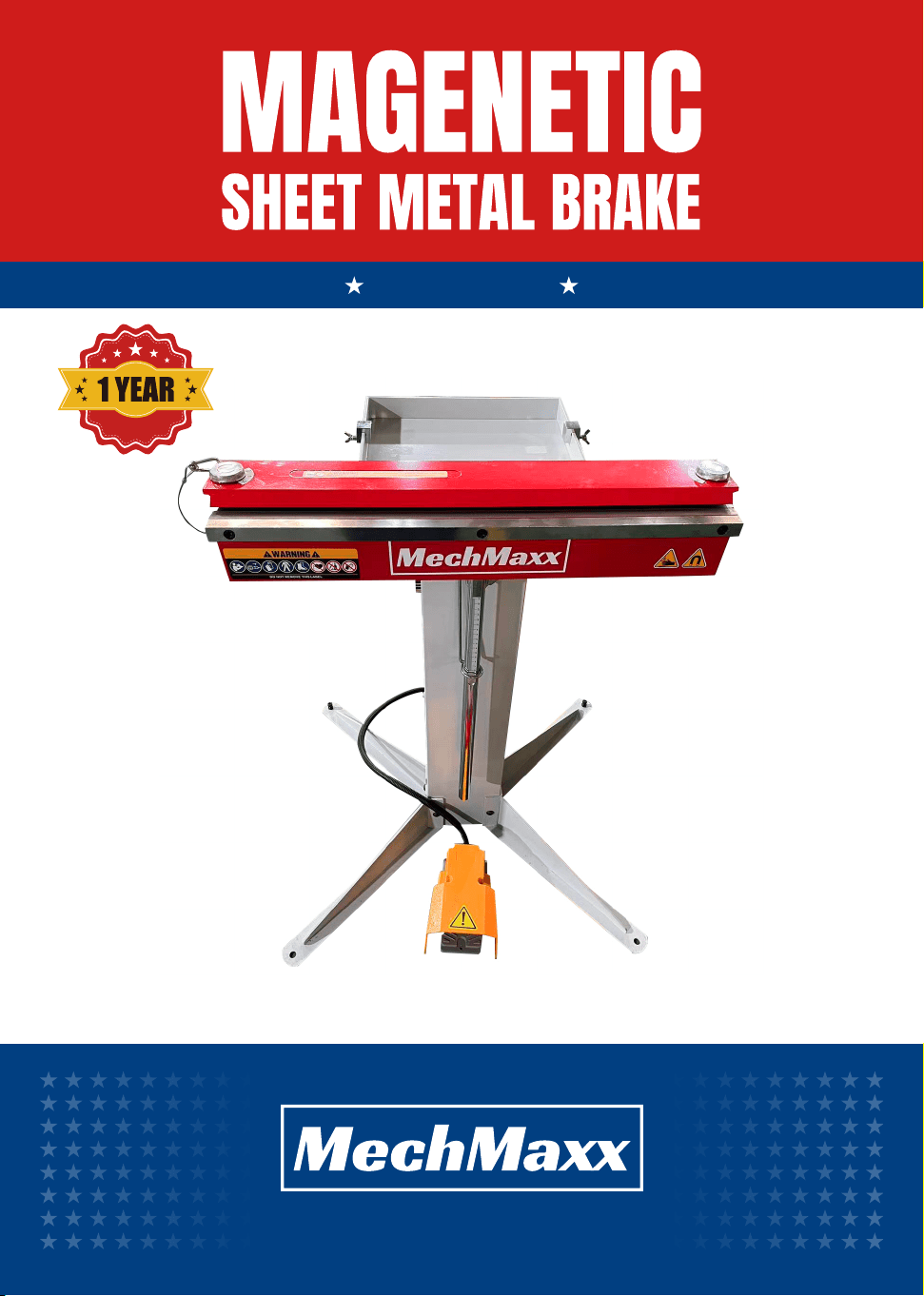
Operator’s Manual
www. mechmaxx.com
WARRANTY
Model: MSMB650E-R


1
www. mechmaxx.com
TABLE OF CONTENTS
TABLE OF CONTENTS
ELECTRICAL SCHEMATIC
9
MAINTENANCE 8
OPRERATIONS 6
INSTALLATIONS 5
PACKING LIST 4
INTRODUCTION 3
SPECIFICATIONS 2
2
www. mechmaxx.com
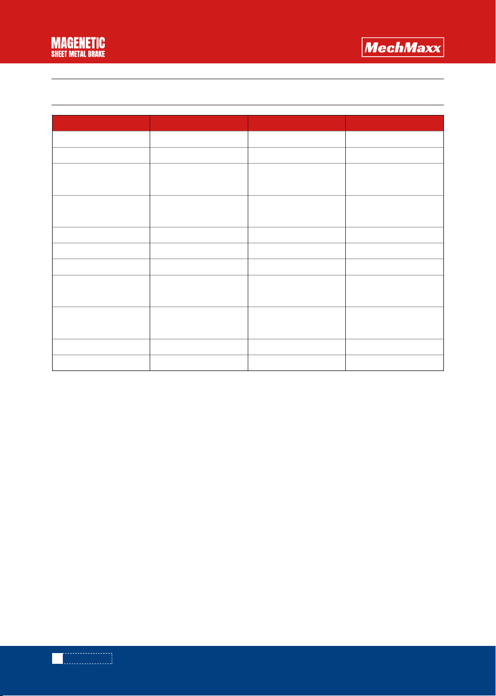
SPECIFICATIONS
SPECIFICATIONS
Power 110V (±5%), 1ph, 60hz, 8A 220V (±5%), 1ph, 60hz, 12A 220V (±5%), 1ph, 60hz, 15A
MODEL MSMB650E-R MSMB1250E-R MSMB2500E
Max Matrial Width 610mm(24inch) 1220mm(48 inch) 2438mm(96 inch)
Max Capacity of
Mild Steel and Aluminum
16. gauge mild steel 16. gauge mild steel 18. gauge mild steel
Max Capacity of
Stainless Steel
20. gauge stainless steel 20. gauge stainless steel 21. gauge stainless steel
Duty Cycle 30% 30% 30%
Rotation Angle 180° 180° 180°
Clamping Force 3 Tonne 6 Tonne 12 Tonne
Shipping Weight 189.6 lbs(86kg) 385.8 lbs(175kg) 551.2 lbs(250kg)
Foot Pedal Included Included Included
Overall Assembled
Dimensions (L x W x H)
27.17” × 37.01” × 35.43”
(690*940*900mm)
51.97”×37.80”× 35.43”
(1320*960*900mm)
101.97” ×36.22”× 35.43”
(2590*920*900mm)
Shiping
Dimensions (L x W x H)
33.46” × 15.75” × 16.54”
(850*400*420mm)
57.09”× 15.75”× 17.72”
(1450*400*450mm)
106.30”× 15.75”×17.72”
(2700*400*450mm)
3
www. mechmaxx.com
INTRODUCTION
INTRODUCTION
Your new Magenetic Sheet Metal Brake is designed to
exceed your expectations. Manufactured under stringent
quality standards, it meets superior performance criteria.
You will find it easy and safe to operate, and with proper
care, it will provide many years of reliable service.
If you encounter any issues, please refer to the manual
for guidance. If a solution cannot be found, contact us
for assistance. Be sure to have the machine's serial
number and production year (located on the nameplate)
ready. For replacement parts, refer to the assembly
numbers provided in the parts list drawings.
For more information, visit our website:
www.mechmaxx.com
This manual contains essential safety guidelines for the
proper setup, operation, maintenance, and servicing of
this machine/equipment. Failure to read, understand,
and follow the instructions may result in serious injury,
including amputation, electrocution, or even death.
The owner is fully responsible for the safe use of this
machine/equipment. This includes, but is not limited to,
ensuring proper installation in a secure environment,
training and authorizing personnel, conducting regular
inspections and maintenance, ensuring the manual is
accessible and understood, utilizing safety devices,
maintaining blade/cutter integrity, and wearing personal
protective equipment.
The manufacturer shall not be held liable for any injury
or property damage caused by negligence, insufficient
training, unauthorized modifications, or misuse of the
equipment.
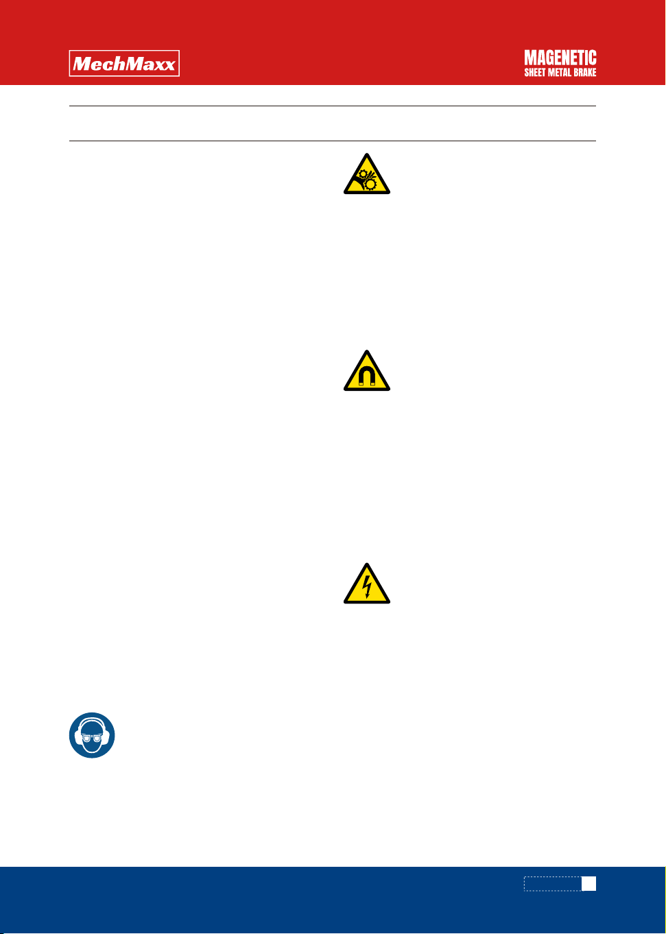
WARNING
SAFETY FOR USE
Wear safety glasses at all times during setup, operation,
and when working near the machinery.
PROTECT YOUR EYES:
Be aware of the clamping leaf on this equipment. This
machine contains multiple moving parts that may cause
injury to you or others nearby.
Loose hair and clothing can become entangled in the
equipment, leading to serious injury. Always secure
loose items before operation.
Never place any part of your body inside the equipment
while it is in use.
HAND OR OTHER BODY PROTECTION:
Electric currents generate magnetic fields, also known
as electromagnetic fields (EMF). These fields may
interfere with pacemakers, medical implants, sensitive
electronic devices, and unattended metal objects.Indi-
viduals with pacemakers or medical implants should
maintain a minimum distance of 12 inches (30 cm)
from the equipment.Prolonged exposure to EMF may
have potential health effects that are not yet fully
understood.
BEWARE OF ELECTRICAL AND MAGNETIC FIELDS:
Exercise extreme caution when operating this machinery,
especially around high-voltage areas. Never assume the
power supply is turned off—always verify before
proceeding. Ensure proper safety measures are in place
at all times.
HIGH VOLTAGE
PACKING LIST
4
www. mechmaxx.com
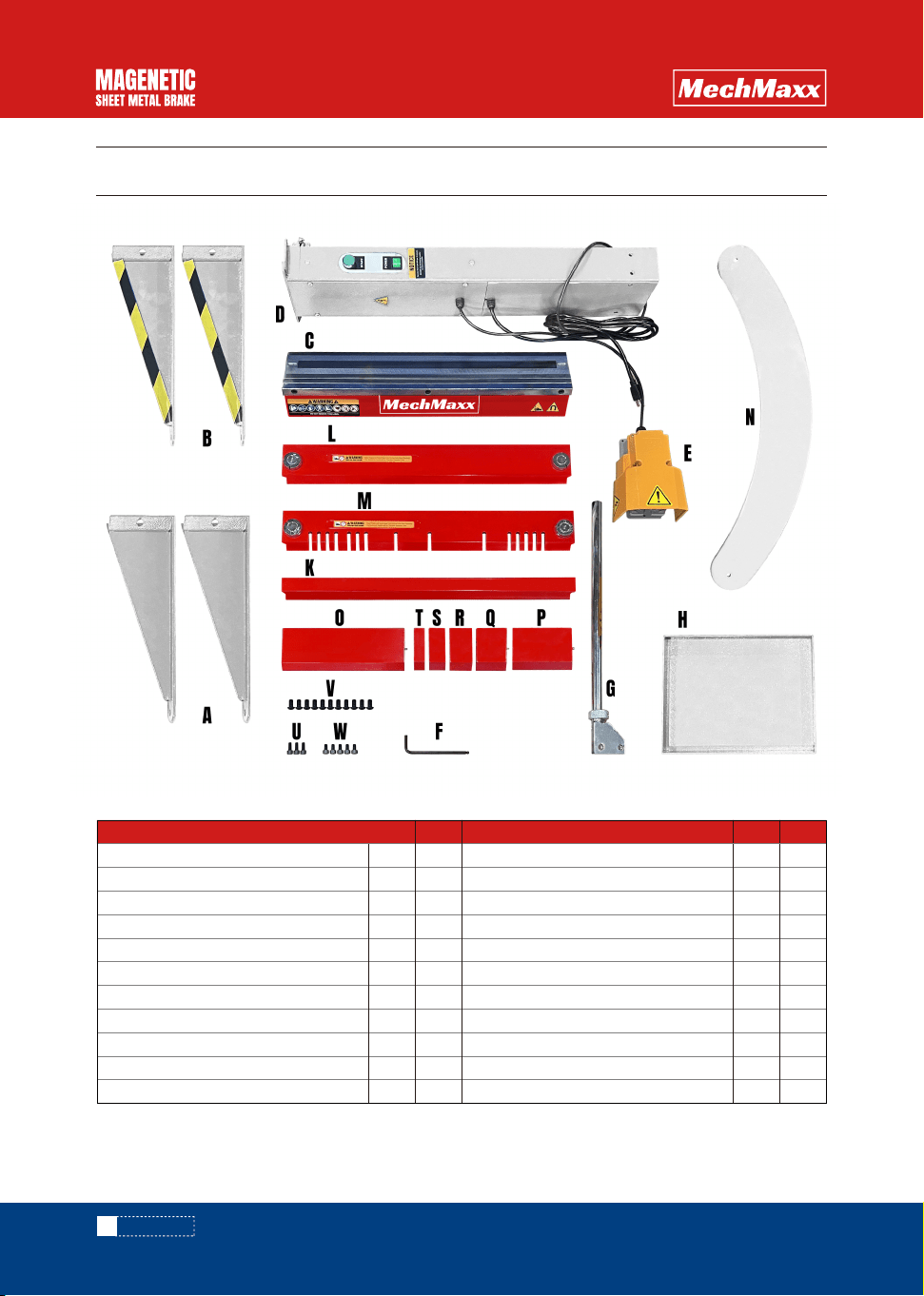
PACKING LIST
QTYQTY
A
B
C
D
E
F
G
H
K
L
M
1
1
1
1
1
1
1
2
10
4
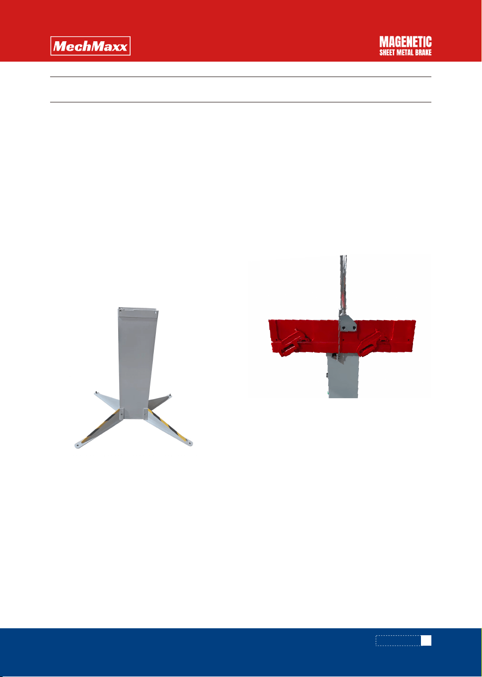
Leg, Rear
Leg, Front (with striped tape)
24" Magenetic Sheet Metal Brake Assembly
Support Colum with Angle Indicator
Foot Pedal, Power Cord
6mm Hex Key
Handle w/ Scale, Stop Collar
Tray and Backstop Clamp with Wing Screw
24"x 2" Solid Clamp Bar
24"x 4" Solid Adjustable Clamp Bar
24"x 4" Slotted Adjustable Clamp Bar
2
2
1
1
1
1
1
1
1
1
1
CONTENTS CONTENTS
Foot Plate
11"x 4" Clamp Bar
5.5"x 4" Clamp Bar
2.75"x 4" Clamp Bar
2"x 4" Clamp Bar
1.5"x 4" Clamp Bar
1"x 4" Clamp Bar
M8x16 Socket Head Screw
M10x16 Rounded Socket Head Screw
M8x12 Socket Head Screw
N
O
P
Q
R
S
T
U
V
W
INSTALLATIONS
5
www. mechmaxx.com
INSTALLATIONS
• Use a Forklift or Lifting Equipment to pass the lifting
section through the lifting straps of the Magnetic
Magenetic Sheet Metal Brake beam[D].
• Lift Magenetic Sheet Metal Brake to the appropriate
position, rotate it 180 degrees, and place it on top of
the Support Column.
• Adjust the power cables of the Magenetic Sheet Metal
Brake to prevent them from being pinched.
• Secure the Magenetic Sheet Metal Brake to the
Support Column completely using M8x12 Socket Head
Screws before removing the lifting straps.
2. Install the Magenetic Sheet Metal Brake
• Adjust the Stop Collar on the Handle w/ Scale, moving
the Stop Collar[G] inward against the mounting tab.
• Lower the Handle through the Angle Indicator, ensuring
the inset Angle Gauge faces outward.
• Rotate the Angle Indicator and Handle upward, aligning
the Bending Beam with the Handle.
• Align the holes in the Handle with the threaded holes
in the Bending Beam.
• Fasten the Handle using two M8x16 Socket Head
Screws.
• Ensure the Handle is square with the Bending Beam
before final tightening.
3. Install the Handle and Angle Indicator
• Attach the Tray [B] to the rear of the Magenetic Sheet
Metal Brake using two M8x12 Socket Head Screws.
4. Install the Tray
• Place the Four Legs[A][B] on the ground and position
the Support Column[D] in the center.
• Ensure that the Two Legs with striped tape[B] are the
front legs.
• Secure all Four Legs using M10x16 Rounded Socket
Head Screws.
• Lift the Front Legs and attach the Foot Plate[N]
underneath.
• If the Metal Sheet Brake is anchored directly to the
floor, the Foot Plate installation is not required.
1. Install the Support Column and Legs
DO NOT run the magnetic brake without material between
the clamping bar and the electromagnetic work bench.
After releasing the electromagnet, residual magnetism
could still hold down the clamp bar.
IMPORTANT
Always wear safety goggles with side shields, protective
footwear, and leather gloves to prevent injuries from
burrs and sharp edges. When handling large or heavy
materials, ensure they are properly supported. Keep
hands and fingers away from the clamping beam, and
stand to the side of the machine to avoid being hit by
the bending apron as it moves upward. The bending
brake presents a pinching hazard, so make sure no body
part or clothing gets caught between the clamping bar
and the bending leaf.
DO NOT run the magnetic brake without material
between the clamping bar and the electromagnetic
work bench. After releasing the electromagnet, residual
magnetism could still hold down the clamp bar.
OPERATION SAFTY
• Ensure that the power is ON at the power outlet and
that the full-length clamp bar is positioned on the
machine with its lifting balls resting in the locating
grooves at each end.
• Adjust for workpiece thickness by rotating the eccentric
adjusters at either end of the clamp bar. Lift the bending
beam up to the 90°position and check that it is parallel to
the edge of the clamp bar. If necessary, readjust the
eccentric lifters. (For optimum results, the gap between
the clamp bar edge and the surface of the bending beam
should be set slightly greater than the thickness of the
metal to be bent.)
• Insert the workpiece, then tilt the front edge of the
clamp bar down and align the bend line with the bending
edge.
• Press and hold the START button to apply pre-clamping.
With the other hand, pull on the handle. Full clamping is
now automatically applied, and the START button should
be released. Continue bending until the required angle is
reached.
• The bending beam may be reversed by approximately
10 ° to 15 ° to relieve pressure on the workpiece for
checking the bend angle. Reversing by more than
15 ° automatically turns the machine off and releases
the workpiece.
GENERAL USAGE
The technique used for folding lips depends on the
workpiece thickness and, to some extent, on its length
and breadth.
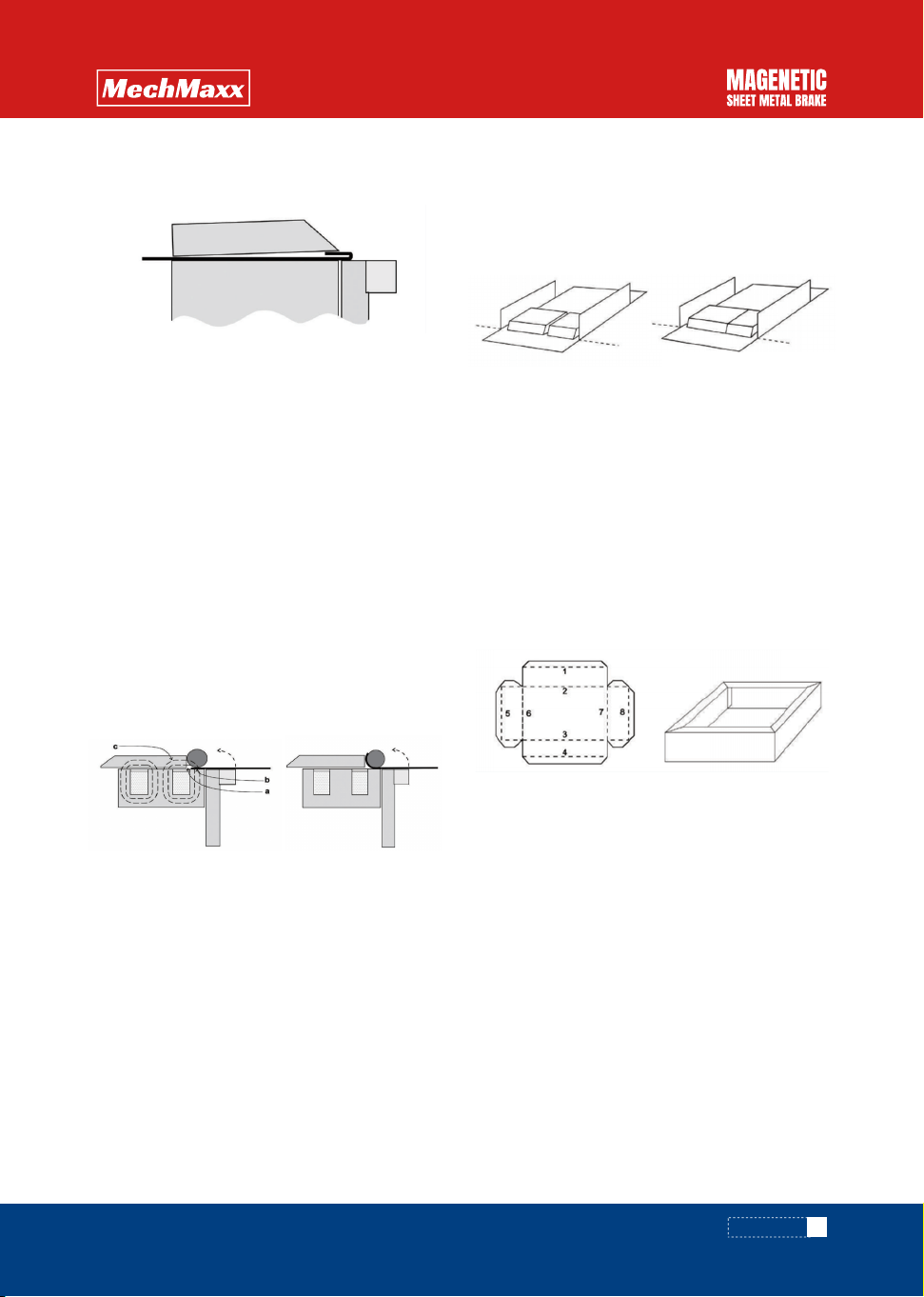
CREATING A HEMMED/CRIMPED EDGE
ON A PANEL(HEM)
1. Proceed as for normal bending but continue the bend
as far as possible (135°).
2. Remove the clamp bar and leave the workpiece on
the machine, but move it rearward about 0.394inch
(10mm). Now, swing the bending beam over to
compress the lip. (Clamping does not need to be
applied).
THIN WORKPIECES (UP TO 0.03 INCH)
BEND CONFIGURATIONS
OPRERATIONS
6
www. mechmaxx.com
OPRERATIONS
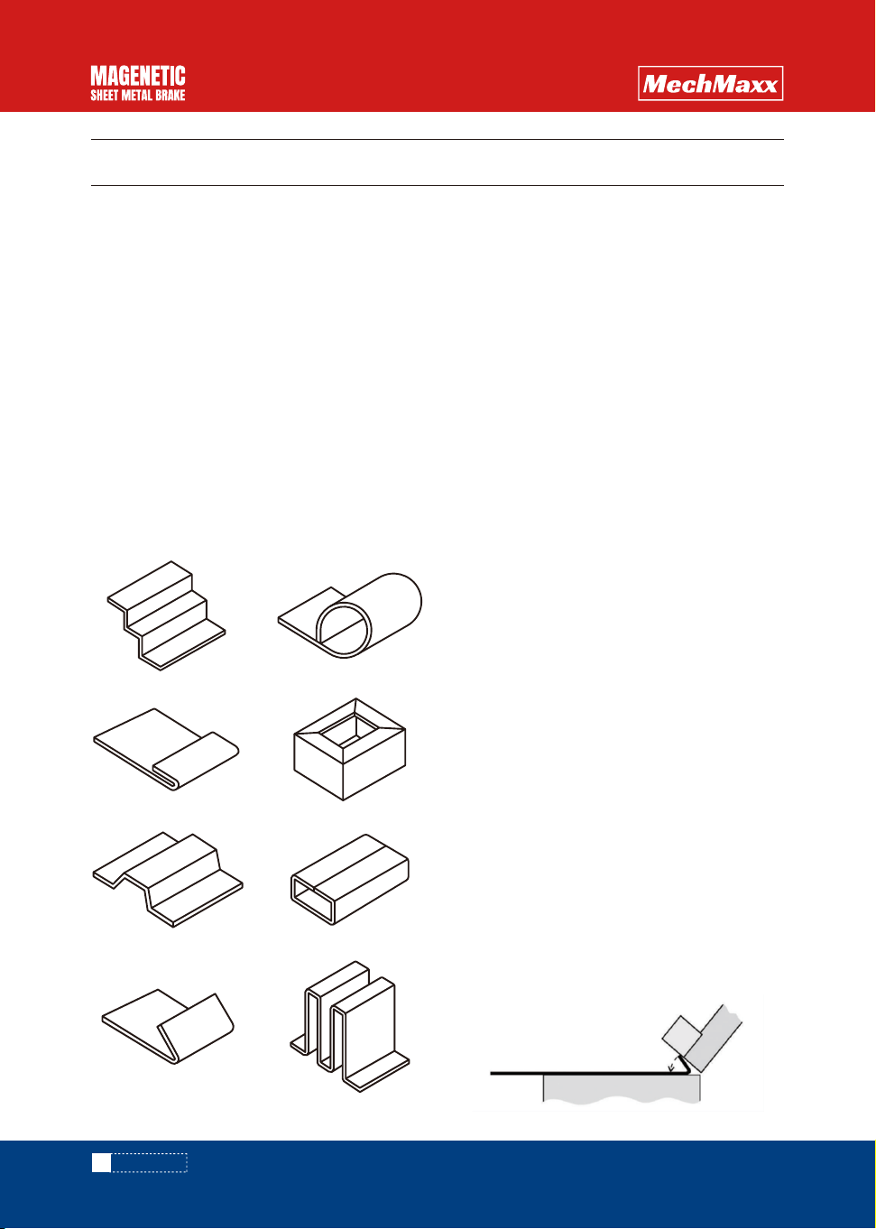
Return Bends
Hem
Stiffening Rib
Angle Bend Fins
Closed Channel
Box
Rolled Edge
7
www. mechmaxx.com
OPRERATIONS
Rolled edges are formed by wrapping the workpiece
around a round steel bar or a piece of thick-walled pipe.
1.Position the workpiece, clamp bar, and rolling bar as
shown.
• Ensure that the clamp bar does not overlap the front
pole of the machine at point “a,” as this would allow
magnetic flux to bypass the rolling bar, resulting in
weak clamping.
• Make sure the rolling bar is resting on the steel front
pole of the machine ( “b” ) and not further back on the
aluminum part of the surface.
• The purpose of the clamp bar is to provide a magnetic
pathway (“c”) into the rolling bar.
2.Wrap the workpiece as far as possible and repeat,
then reposition as shown.
FORMING A ROLLED EDGE
• Operate the Bender normally using the Short Clamp
Bars to form the box sides.
As you gain experience in forming boxes, more complex
features like tabs, flaps, and flanges can be added to
the sides of the box.
The Bender is used in the same way as for normal
straight bends, but instead of one of the 24" Clamp
Bars, the appropriate width of Short Clamp Bars is used
for the secondary sides of the box.
• Operate the Bender normally for the first two opposite
ends of the box.
• Determine the width of the Short Clamp Bars required
for the bends needed to form the secondary width of the
box.
• Position the partially formed box workpiece on the
Base Deck.
• Place the Short Clamp Bars over the inside of the box
workpiece.
MAKING BOXES
To avoid the risk of damaging the bending edge of the
clamp bar or denting the top surface of the magnet body,
do not place small objects under the clamp bar. The
recommended minimum bend length using the standard
clamp bar is 0.591inch(15mm), except when the work-
piece is very thin or soft.
The clamping force of the magnet is reduced when it is
hot. Therefore, to achieve the best performance, apply
clamping for no longer than necessary to complete the
bend.
CAUTION
As features like tabs, flaps, and flanges are incorporated
into the box sides, the clearance provided by the slots in
the Slotted Clamp Bar becomes necessary. The Slotted
Clamp Bar is used together with the Short Clamp Bars.
• Follow the procedure described in NORMAL, STRAIGHT
BENDS for the initial bends of the tray sides.
• The Slotted Clamp Bar is set up similarly to the Solid
Clamp Bar, but the open slots will allow the tray sides
and flaps to pass through as the project becomes more
intricate.
FORMING TRAYS
(USING THE SLOTTED CLAMP BAR)
3. With thin workpieces and/or when the lip is not too
narrow, a more complete flattening can be achieved by
following up with magnetic clamping only.

• Use a liberal amount of a good quality, heavy bodied chassis grease on the slide surfaces of the two hinges.
• Apply a thin motor or suitable lubricating oil to the pivoting portion of the hinges.
• Always keep the magnetic Base Deck of the Bender clean and free of any dirt accumulation or metal chips.
• Keep the surfaces of the Clamping Bars free of dirt and metal chips.
• Always keep Magenetic Sheet Metal Brake in a dry location and store with a suitable cover in place.
• Keep all bare metal areas including the Base Deck lightly oiled to prevent rust formation when not in use.
MAINTENANCE
8
www. mechmaxx.com
MAINTENANCE
ELECTRICAL SCHEMATIC
9
www. mechmaxx.com
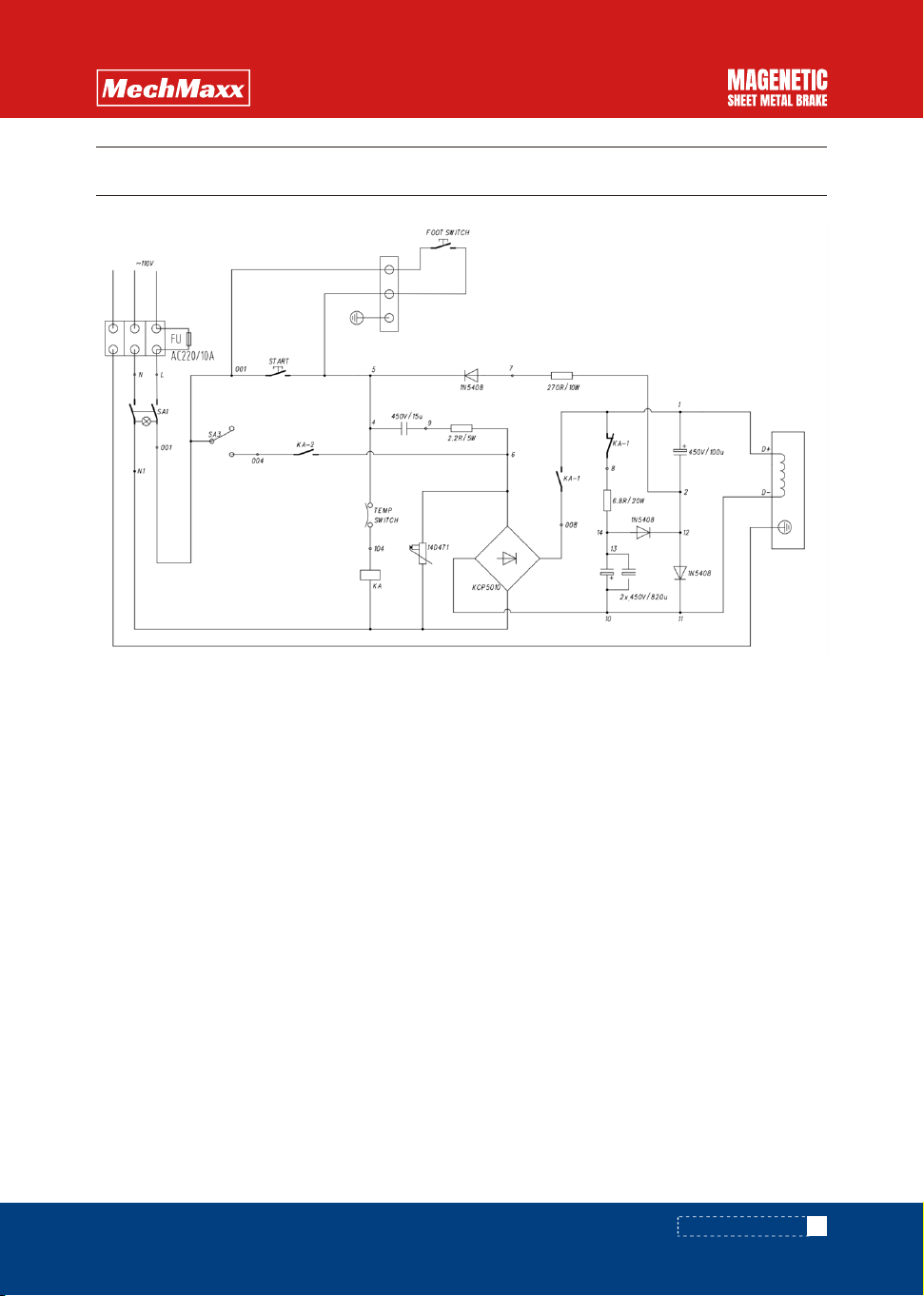
ELECTRICAL SCHEMATIC