
Technical Support and E-Warranty Certificate www.vevor.com/support
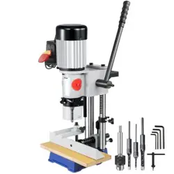
HOLLOW CHISEL MORTISE MACHINE
INSTRUCTIONS
MODEL:MS36127A3
We continue to be committed to provide you tools with competitive price.
"Save Half", "Half Price" or any other similar expressions used by us only represents an
estimate of savings you might benefit from buying certain tools with us compared to the major
top brands and does not necessarily mean to cover all categories of tools offered by us. You
are kindly reminded to verify carefully when you are placing an order with us if you are
actually saving half in comparison with the top major brands.

- 1 -
MODEL:MS36127A3
FSJ36127A3Y550001V FSJMS36127A3Y0001V2
Have product questions? Need technical support? Please feel free to
contact us:
Technical Support and E-Warranty Certificate
www.vevor.com/support
NEED HELP? CONTACT US!
HOLLOW CHISEL MORTISE
MACHINE

- 2 -
This is the original instruction, please read all manual instructions
carefully before operating. VEVOR reserves a clear interpretation of our
user manual. The appearance of the product shall be subject to the
product you received. Please forgive us that we won't inform you again if
there are any technology or software updates on our product.
Warning-To reduce the risk of injury, user must read
instructions manual carefully.
This device complies with Part 15 of the FCC Rules. Operation is
subject to the following two conditions:(1)This device may not cause
harmful interference, and (2)this device must accept any interference
received, including interference that may cause undesired operation.
This product is subject to the provision of European Directive
2012/19/EC. The symbol showing a wheelie bin crossed
through indicates that the product requires separate refuse
collection in the European Union. This applies to the product
and all accessories marked with this symbol. Products marked
as such may not be discarded with normal domestic waste, but
must be taken to a collection point for recycling electrical and
electronic devices
GENERAL SAFETY RULES
Woodworking can be dangerous if safe and proper operating
procedures are not followed. As with all machinery, there are
certain hazards involved with the operation of the product. Using
the machine with respect and caution will considerably lessen the
possibility of personal injury. However, if normal safety
precautions are overlooked or ignored, personal injury to the

- 3 -
operator may result. Safety equipment such as guards, push
sticks, hold-downs, featherboards, goggles, dust masks and
hearing protection can reduce your potential for injury. But even
the best guard will not make up for poor judgment, carelessness or
inattention. Always use common sense and exercise caution in the
workshop. If a procedure feels dangerous, do not try it. Figure out
an alternative procedure that feels safer.REMEMBER: Your
personal safety is your responsibility.
This machine was designed for certain applications only. We
strongly recommend that this machine cannot be modified and/or
used for any application other than that for which it was designed.
If you have any questions relative to a particular application, DO
NOT use the machine until you have first contacted your local
dealer to determine if it can or should be performed on the
product.
WARNING: FAILURE TO FOLLOW THESE RULES MAY
RESULT IN SERIOUS PERSONAL INJURY.
1.FOR YOUR OWN SAFETY, READ INSTRUCTION MANUAL BEFORE
OPERATING THE TOOL. Learn the tool’s application and limitations as well as
the specific hazards peculiar to it.
2.KEEP GUARDS IN PLACE and in working order.
3.ALWAYS WEAR EYE PROTECTION. Wear safety glasses. Everyday
eyeglasses only have impact resistant lenses; they are not safety glasses. Also
use face or dust mask if cutting operation is dusty.
4.REMOVE ADJUSTING KEYS AND WRENCHES. Form habit of checking to see
that keys and adjusting wrenches are removed from tool before turning it “on”.
5.KEEP WORK AREA CLEAN. Cluttered areas and benches invite accidents.
6.DO NOT USE IN DANGEROUS ENVIRONMENT. Do not use power tools in
damp or wet locations, or expose them to rain. Keep work area well-lighted.
7.KEEP CHILDREN AND VISITORS AWAY. All children and visitors should be
kept a safe distance from work area.
8.MAKE WORKSHOP CHILDPROOF – with padlocks, master switches, or by
removing starter keys.

- 4 -
9.DO NOT FORCE TOOL. It will do the job better and be safer at the rate for which
it was designed.
10.USE RIGHT TOOL. Do not force tool or attachment to do a job for which it was
not designed.
11.WEAR PROPER APPAREL. No loose clothing, gloves, neckties, rings,
bracelets, or other jewelry to get caught in moving parts. Nonslip footwear is
recommended. Wear protective hair covering to contain long hair.
12.SECURE WORK. Use clamps or a vise to hold work when practical. It is safer
than using your hand and frees both hands to operate too.
13.DO NOT OVERREACH. Keep proper footing and balance at all times.
14.MAINTAIN TOOLS IN TOP CONDITION. Keep tools sharp and clean for best
and safest performance. Follow instructions for lubricating and changing
accessories.
15.DISCONNECT TOOLS before servicing and when changing accessories such
as blades, bits, cutters etc.
16.USE RECOMMENDED ACCESSORIES. The use of accessories and
attachments not recommended by manufacturer may cause hazards or risk of
injury to persons.
17.REDUCE THE RISK OF UNINTENTIONAL STARTING. Make sure switch is in
“OFF” position before plugging in power cord. In the event of a power failure,
move switch to the “OFF” position.
18.NEVER STAND ON TOOL. Serious injury could occur if the tool is tipped or if
the cutting tool is accidentally contacted.
19.CHECK DAMAGED PARTS. Before further use of the tool, a guard or other
part that is damaged should be carefully checked to ensure that it will operate
properly and perform its intended function – check for alignment of moving parts,
binding of moving parts, breakage of parts, mounting, and any other conditions
that may affect its operation. A guard or other part that is damaged should be
properly repaired or replaced.
20.DIRECTION OF FEED. Feed work into a blade or cutter against the direction of
rotation of the blade or cutter only.
21.NEVER LEAVE TOOL RUNNING UNATTENDED. TURN POWER OFF. Do
not leave tool until it comes to a complete stop.
22.STAY ALERT, WATCH WHAT YOU ARE DOING, AND USE COMMON SENSE

- 5 -
WHEN OPERATING A POWER TOOL. DO NOT USE TOOL WHILE TIRED OR
UNDER THE INFLUENCE OF DRUGS, ALCOHOL, OR MEDICATION. A moment
of inattention while operating power tools may result in serious personal injury.
23.MAKE SURE TOOL IS DISCONNECTED FROM POWER SUPPLY while
motor is being mounted, connected or reconnected.
24.THE DUST GENERATED by certain woods and wood products can be
injurious to your health. Always operate machinery in well ventilated areas and
provide for proper dust removal. Use wood dust collection systems whenever
possible.
25.WARNING: SOME DUST CREATED BY POWER SANDING, SAWING,
GRINDING, DRILLING, AND OTHER CONSTRUCTION ACTIVITIES contains
chemicals known to cause cancer, birth defects or other reproductive harm.
Some examples of these chemicals are:
lead from lead-based paints.
crystalline silica from bricks and cement and other masonry products.
arsenic and chromium from chemically-treated lumber.
Your risk from these exposures varies, depending on how often you do
this type of work. To reduce your exposure to these chemicals: work in a
well ventilated area, and work with approved safety equipment, such as
those dust masks that are specially designed to filter out microscopic
particles.
ADDITIONAL SAFETY RULES FOR HOLLOW CHISEL MORTISERS
1. DO NOT OPERATE THIS MACHINE until it is assembled and installed
according to the instructions.
2. OBTAIN ADVICE FROM YOUR SUPERVISOR, instructor, or another
qualified person if you are not familiar with the operation of this machine.
3. FOLLOW ALL WIRING CODES and recommended electrical connections.
4. MAKE CERTAIN the machine is fastened to a supporting surface to prevent it
from tipping over during operation.

- 6 -
5. NEVER turn the mortiser “ON” before clearing the table of all objects (tools,
scrap pieces, etc.).
6. ALWAYS keep hands, fingers and hair away from the rotating bit.
7. DO NOT attempt to mortise material that does not have a flat surface, unless a
suitable support is used.
8. ALWAYS position holddown directly over workpiece to prevent workpiece from
lifting during operation.
9. ALWAYS support workpiece securely against fence to prevent rotation.
10. BE SURE drill bit is sharp, not damaged, and properly secured in the chuck
before operation.
11. MAKE SURE chuck key is removed before starting machine.
12. NEVER turn on the power with the drill bit or chisel contacting the workpiece.
13. NEVER perform layout, assembly, or set-up work on the table while the
mortiser is operating.
14. ADJUST the depth stop to avoid drilling into the table.
15. ALWAYS turn off the power before removing scrap pieces from the table.
16. SHUT-OFF the power, remove the drill bit and chisel, and clean the table
before leaving the machine.
17. FOR YOUR OWN SAFETY – Don ’ t wear gloves when operating the
machine.
18. SHOULD any part of your tool be missing, damaged, or fail in any way, or any
electrical component fail to perform properly, shut off switch and remove plug
from power supply outlet. Replace missing, damaged, or failed parts before
resuming operation.
19. THE USE of attachments and accessories not recommended by Delta may
result in the risk of injuries.
20. TURN THE MACHINE “OFF” AND DISCONNECT THE MACHINE from the
power source before installing or removing accessories, before adjusting or
changing set-ups, or when making repairs.
21. TURN THE MACHINE“OFF”, disconnect the machine from the power source,

- 7 -
and clean the table/work area before leaving the machine. LOCK THE SWITCH
IN THE “OFF” POSITION to prevent unauthorized use.
WARNING: FAILURE TO FOLLOW THESE RULES MAY RESULT IN SERIOUS
PERSONAL INJURY.
SAVE THESE INSTRUCTIONS.
Refer to them often
and use them to instruct others.
POWER CONNECTIONS.
A separate electrical circuit should be used for your tools. If an extension
cord is used, use only 3-wire extension cords, which have grounding type
plugs and receptacles, which accept the tool’s plug. Before connecting the
motor to the power line, make sure the switch is in the“OFF”position and
be sure that the electric current is of the same characteristics as indicated
on the tool.
All line connections should make good contact. Running on low voltage will damage
the motor.
WARNING: DO NOT EXPOSE THE TOOL TO RAIN OR OPERATE THE
TOOL IN DAMP LOCATIONS
MOTOR SPECIFICATIONS
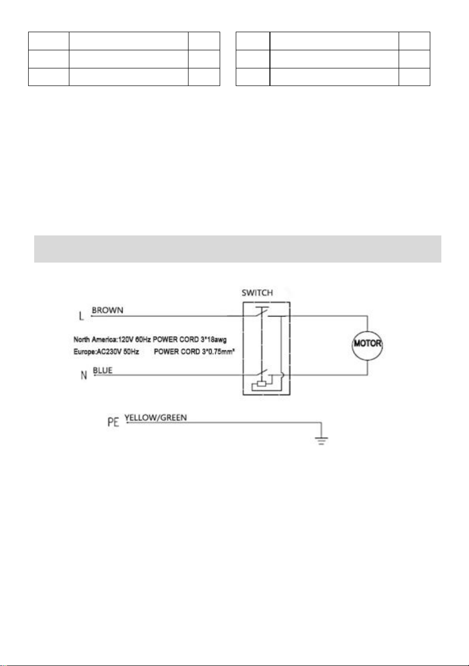
Your tool is wired for: Europe230V 50Hz or North America120V 60Hz alternating
current. Before connecting the tool to the power source, make sure the machine is cut
off from power source.
CONNECTING TOOL TO POWER SOURCE

- 8 -
GROUNDING INSTRUCTIONS
WARNING: THIS TOOL MUST BE GROUNDED WHILE IN USE TO
PROTECT THE OPERATOR FROM ELECTRIC SHOCK.
All grounded, cord-connected tools:
1. In the event of a malfunction or breakdown, grounding provides a path
of least resistance for electric current to reduce the risk of electric shock.
This tool is equipped with an electric cord having an equipment-grounding
conductor and a grounding plug. The plug must be plugged into a matching
outlet that is properly installed and grounded in accordance with all local
codes and ordinances.
2. Do not modify the plug provided - if it will not fit the outlet, have the
proper outlet installed by a qualified electrician.
3. Improper connection of the equipment-grounding conductor can result
in risk of electric shock. The conductor with insulation having an outer
surface that is green with or without yellow stripes is the
equipment-grounding conductor. If repair or replacement of the electric
cord or plug is necessary, do not connect the equipment-grounding
conductor to a live terminal.
4. Check with a qualified electrician or service personnel if the grounding
instructions are not completely understood, or if in doubt as to whether the
tool is properly grounded.
5. Use only 3-wire extension cords that have grounding type plugs and
receptacles that accept the tool’s plug.
6. Repair or replace damaged or worn cord immediately.
WARNING: IN ALL CASES, MAKE CERTAIN THE RECEPTACLE IN QUESTION
IS PROPERLY GROUNDED. IF YOU ARE NOT SURE, HAVE A QUALIFIED
ELECTRICIAN CHECK THE RECEPTACLE.
Use proper extension cords. Make sure your extension cord is in good
condition and is a 3-wire extension cord, which has a grounding type plug and a
receptacle, which will accept the tool’s plug. When using an extension cord, be

- 9 -
sure to use one heavy enough to carry the current of the tool. An undersized
cord will cause a drop in line voltage, resulting in loss of power and overheating
FOREWORD.
The Fox MS3816R is easier to handle than traditional drilling machines
equipped with mortise attachments. Model MS3816R is made of cast iron
and steel, which is rigid and stable. The mortise is equipped with a
standard 3-jaw key chuck for positive gripping of the tenon.
UNPACKING AND CLEANING.
Carefully unpack the machine and all loose items from the shipping
carton(s). Remove the protective coating from all unpainted surfaces. This
coating may be removed with a soft cloth moistened with kerosene (do not
use acetone, gasoline or lacquer thinner for this purpose). After cleaning,
cover the unpainted surfaces with a good quality household floor paste
wax.
NOTICE: THE MANUAL COVER PHOTO ILLUSTRATES THE CURRENT
PRODUCTION MODEL. ALL OTHER ILLUSTRATIONS ARE REPRESENTATIVE
ONLY AND MAY NOT DEPICT THE ACTUAL COLOR, LABELING OR
ACCESSORIES AND MAY BE INTENDED TO ILLUSTRATE TECHNIQUE ONLY.
NOTICE: The operation diagram is for reference only, and the
actual accessories of the product are subject to the actual product,
and the operation and use methods remain unchanged.
INSTRUCTIONS FOR OPERATING THE DEVICE
- 10 -
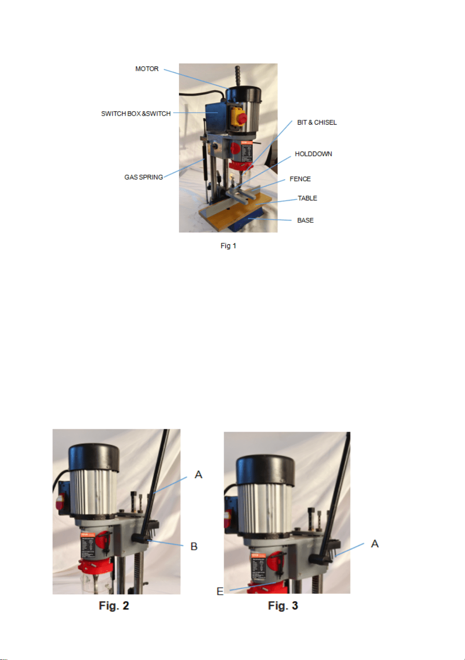
HOLLOW CHISEL MORTISER PARTS.(See Figure 1).
WARNING: FOR YOUR OWN SAFETY, DO NOT CONNECT THE
MACHINE TO THE POWER SOURCE UNTIL THE MACHINE IS
COMPLETELY ASSEMBLED AND YOU READ AND UNDERSTAND THE
ENTIRE INSTRUCTION MANUAL.
Lifting handle and gas spring.
1.Assemble hub of handle assembly (A) Fig. 2, to gear shaft (B) and
secure the handle to gear shaft using screw.
- 11 -
2. Raise mortising machine head (E) Fig. 3, to the up position by turning handle
(A)clockwise.
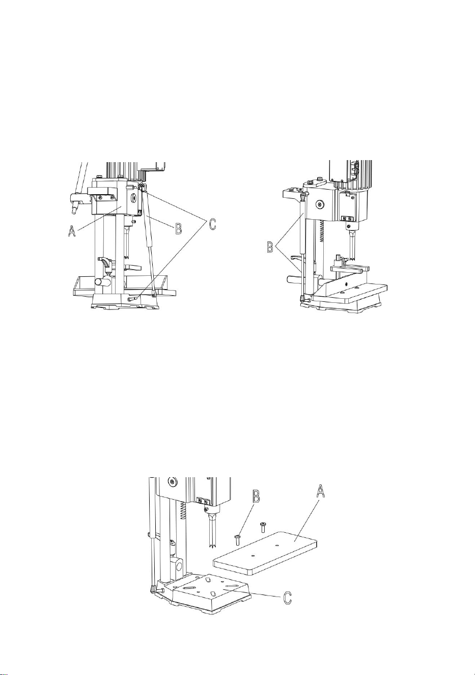
3.Make sure head (A) Fig.4, is held in the up position and assemble the gas spring
Fig.
(B) to the two fittings (C), one located on the column and the other on the back
of the head.
4 Fig. 5
4.Fig. 5, illustrates the gas spring (B) assembled to the machine. The gas spring
(B) keeps the head in the up position.
Work surface.
1.Assemble the table (A) Fig. 6, to the base using the two M6x1x35mm flat head
screws (B) Insert the two screws (B) into the two holes (D) in table (A). Place the
two T-nuts (C) into the slots (E) provided in the bottom of the base and tighten
the two screws (B) into the two T-nuts (C) securely.
Fig. 6
- 12 -
2.The table (A) Fig. 6, can be moved in or out by loosening the two screws (B), and
re-positioning the table, and then tightening screws (B).
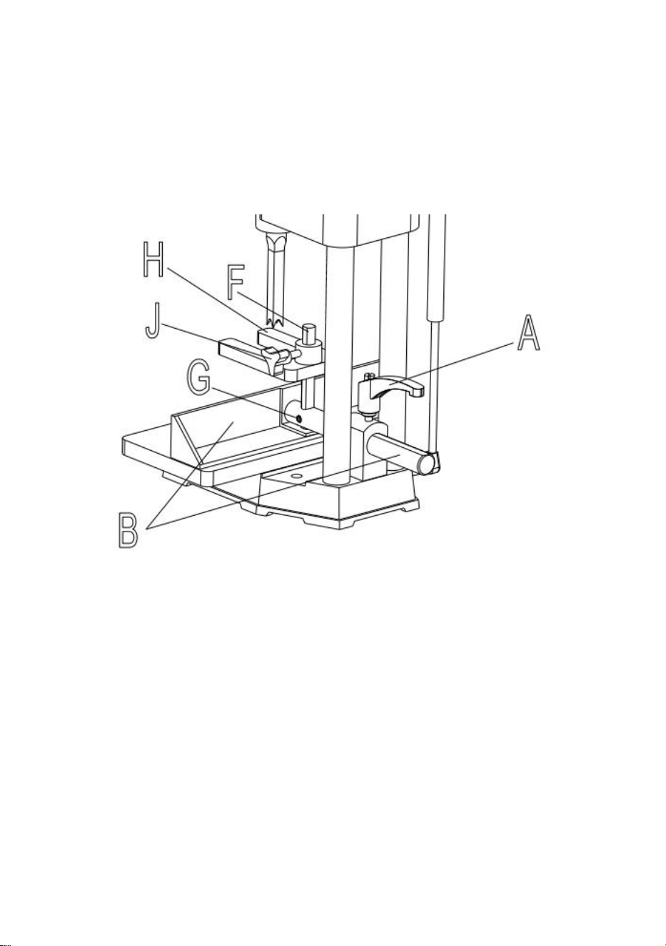
FENCE AND HOLDDOWN.
1.Locate handle assembly and remove screw (A) Fig.7, and spring (B) from handle
(C). Sperate handle (C) from stud (D).
Fig.7
2.Insert bar of fence assembly (E) Fig. 7, through hole in column as shown.
Tighten handle (C) against flat on fence bar to hold fence in position.
NOTE: Handle (C) is spring-loaded and can be repositioned on the stud
located underneath the handle by pulling out the handle and
repositioning it on the stud.
3.Insert bar (F) Fig. 7, into hole on top of fence as shown, and tighten set
screw (G) against flat on bar (F).
4.Assemble the hold down (H) Fig. 7, onto bar (F) as shown, and tighten
set screw (J) against flat on bar.
- 13 -
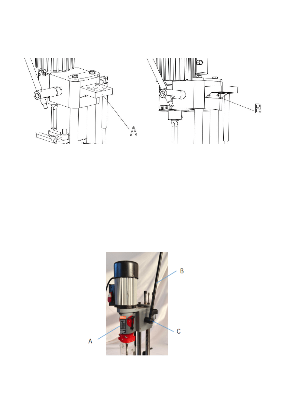
TOOL AND CHISEL HOLDER.
1.Assemble tool and chisel holder (A) Fig8, to side of column using the two
M6x1x25mm screws (B) and M6 flat washers as shown.
Fig8
2.Illustrates the chuck key, wrench and chisels and bits in holes of tool and
chisel holder (A) when not in use.
RAISING AND LOWERING THE HEAD.
The head (A) Fig. 9, is raised and lowered by means of the lever (B). For
maximum leverage during the mortising operation, the lever (B) can be
repositioned by pulling out the hub (C) of the lever assembly and
repositioning hub on the pinion shaft.
Fig. 9
- 14 -
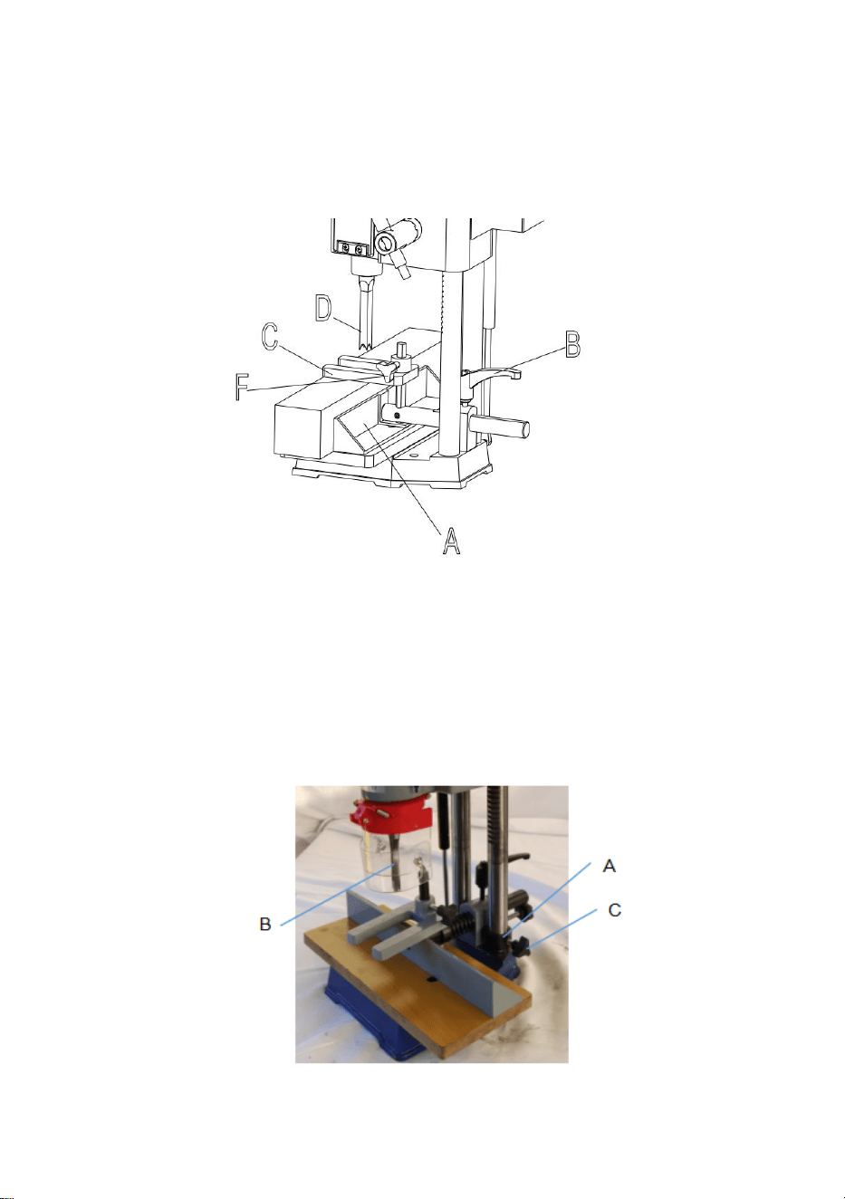
FENCE.
The fence (A) Fig10, can be moved in or out by loosening lever (B), sliding fence
to the desired position and tightening lever (B). NOTE: Lever (B) is spring-loaded
and can be repositioned by pulling out on the lever and repositioning it on the
serrated nut located underneath the lever.
Fig. 10
DEPTH STOP.
A depth stop guide (A) Fig. 11, is provided to limit the depth of the chisel
(B). To adjust the depth stop guide (A), loosen screw (C) and lower head
until the chisel (B) is at the desired depth. Lower depth stop guide (A) until
it is at the desired depth, tighten screw (C).
Fig. 11
- 15 -
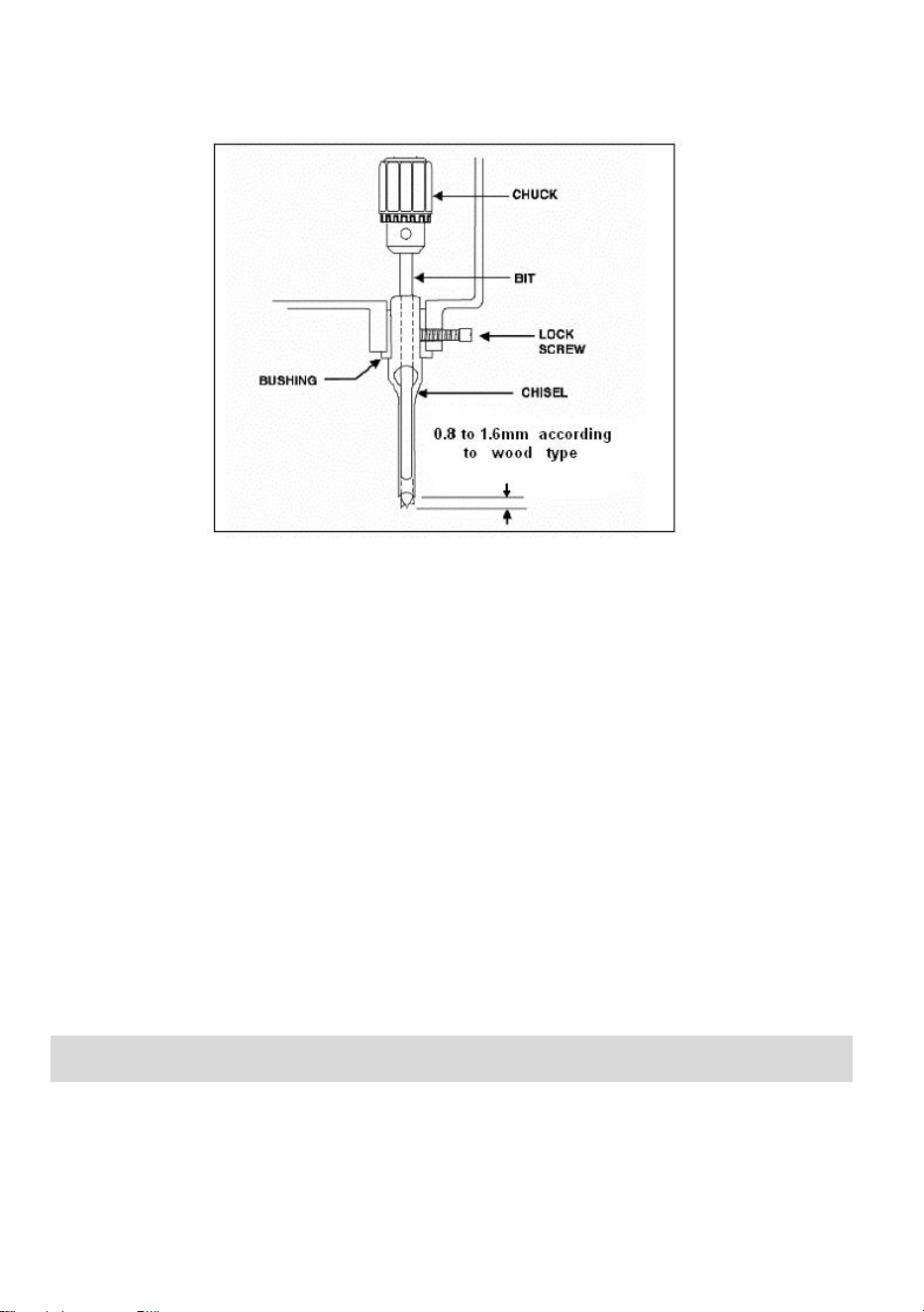
INSTALLING CHISEL & BIT.
1. Loosen lock screw, shown in Figure 12.
Fig. 12
2. Insert chisel bushing (with the hole facing forward) into the head.
Tighten the screw just enough to hold the chisel in place.
NOTE: Set the slot in the side of the chisel to the left or right, NOT to the front or
back. This will allow chips to escape when cutting mortises.
3. Push the chisel up as far as possible into the head. Then lower the
chisel approximately 0.8mm to 1.6mm, depending on the type of wood
being worked. Tighten the screw to hold chisel in place.
4. Push bit up through the chisel opening as far as it will go. Lock the drill
bit in place with the chuck key.
5. Loosen screw and push chisel up against the bushing, then tighten
screw. This should provide the proper distance between the points of
the chisel and the bit.
The Mortiser requires only minor maintenance, such as cleaning and
lubrication and routine adjustment and sharpening of the chisel and bit.
Dust the machine down after each use and, as necessary, use light
applications of oil or grease to lubricate linkages, moving parts, etc.
MAINTENANCE
- 16 -
Chisels and drill bits should be kept sharp for optimal performance. Blunt
edges will give inaccurate results on the mortise and tenon, which can lead
to overheating and breakage to chisel or bite. If the chisel and drill bit are
badly worn and difficult to sharpen, they should be replaced.
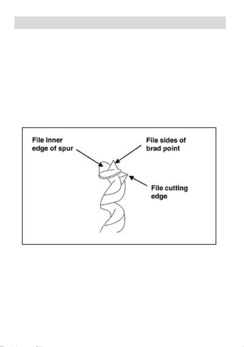
Sharpen the bit by using a small, smooth file, following the original shape
of the bit. File the inside edge of the spur, the sides of the brad point, and
the cutting edge inwards toward the flute of the bit. See Fig 13. Do not
file the outside edge of the spur as this will affect the diameter of the bit.
Fig 13
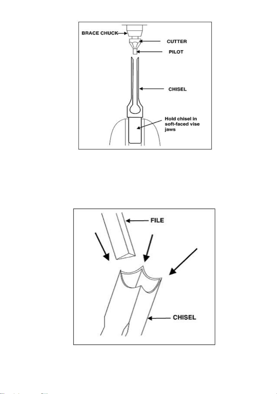
Sharpen the chisel with a mortise and tenon chisel with the correct size
guide. (Pilot size will vary depending on the size of the chisel). Two to
three turns of the cutter in the carpenter's bracket chuck are enough to
sharpen the chisel, as shown in Figure 14.
SHARPENING CHISEL & BIT
- 17 -
Fig 14
Use a small, triangular, smooth file to relieve the inner corners of the
chisel. See Fig.15.Remove any burrs from the outside of the chisel with
a fine oilstone.
Fig 15
- 18 -
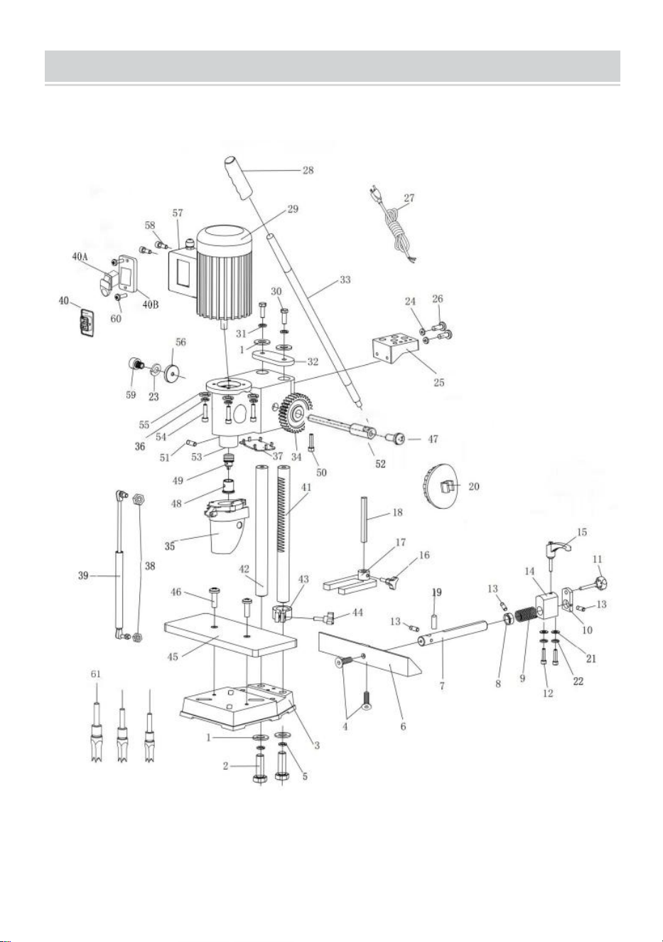
PARTS DRAWINGS AND PARTS LISTS
Parts Diagram

- 19 -
PART LIST
NO.
DESCRIPTION
QTY
NO.
DESCRIPTION
QTY
1
LOCK WASHER
4
32
STEP PLATE
1
2
BOLT
2
33
HANDLE
1
3
BASE
1
34
GEAR
1
4
SCREW
2
35
CHIP GUARD
1
5
WASHER
2
36
WASHER
3
6
FENCE
1
37
PLASTIC COVER
1
7
FENCE ROD
1
38
NUT
2
8
FENCE COLLAR
1
39
GAS SPRING
1
9
SPRING
1
40
SWITCH
1
10
ADJUSTMENT PLATE
1
41
GEAR COLUMN
1
11
ADJUSTMENT KNOB
1
42
GUIDE COLUMN
1
12
SCREW
2
43
DEPTH LOCK COLLAR
1
13
SCREW
3
44
DEPTH LOCK KNOB
1
14
GUIDE BLACK
1
45
WOOD TABLE
1
15
LOCK KNOB
1
46
SCREW
2
16
LOCK KNOB
1
47
SCREW
1
17
HOLD DOWN CLAMP
1
48
CHISEL BUSING
1
18
HOLD DOWN ROD
1
49
DRILL CHUCK
1
19
PIN
1
50
SCREW
1
20
COVER
2
51
SCREW
1
21
LOCK WASHER
2
52
GEAR SHAFT
1
22
WASHER
2
53
HEADSTOCK
1
23
WASHER
1
54
SCREW
3
24
WASHER
2
55
LOCK WASHER
3
25
TOOL HOLDER
1
56
COVER
1
26
SCREW
2
57
SWITCH BOX
1
27
POWER CORD
1
58
SCREW
4
28
HANDLE SLEEVE
1
59
SCREW
1
- 20 -
29 MOTOR 1 60 SCREW 2
30 BOLT 2 61 CHISEL 3
31 WASHER 2
WIRING DIAGRAM

- 21 -
ACCESSORIES LIST
SKU:FSJ36127A3Y550001V1/FSJ36127A3Y0001V2
1.Instructions *1
2.1/4 chisel *1
3.3/8 chisel *1
4.1/2 chisel *1
5.Drill chucks *1
6.Cast iron fences *1
7.Allen key *4
8.Handle rod *1
9.Handle *1
10.Handle rod screw hexagon M6*20 *1
11.vertical axis *1
12.Pressing blocks *1
13.Spinner seat + screws *1
14.Tool holders *1
15.Tool holder screws M6*16 + flat washers *2 17.Drill keys *1
16.Drill keys *1
17.Goggles *1
18.Drill clamp shaft *1
19.Wooden board screws M8*26 *2
20.Wooden work boards *1

- 22 -

- 2 3-
,
,
,


Technical Support and E-Warranty Certificate
www.vevor.com/support