
eologix sensor technology gmbh
Kratkystrasse 2 | 8020 Graz | Austria
Created on
09/10/2018
Language
EN
Last update
06/02/2023
OPERATION AND
SERVICE MANUAL
Sensor system
Base station BET214
Ice sensor CET214

OperationandServiceManual_V1_4_EN_eologix
© eologix sensor technology gmbh 2023
eologix.com 2 | 125
Disclosure and reproduction of this documentation as well as processing and sharing its content are prohibited, unless explicitly permitted.
Any breach or infringement will result in liability for damages.
All rights reserved, especially for the event of grant of a patent or registration of a utility model.
©
eologix sensor technology gmbh
2023 All rights reserved.
We have inspected the content of this documentation regarding accordance with the described hardware and software.
Nevertheless, deviations, remaining errors and omissions cannot be excluded, which is why no liability is assumed for damages resulting from
this.
However, the information in this printed document is regularly revised and necessary corrections will be included in the editions to follow. We
appreciate any suggestions for improvement.
Technical modifications reserved!
PREFACE
We thank you for your trust and for choosing our product. Our product has been designed
and manufactured in accordance with Europeans norms and regulations.
Please read this operation manual carefully before commissioning/use. Please contact us in
the event of uncertainties, questions or damages to the product.
Anybody who in any way works with this product must have read, understood and accepted
this document and implement it to the best of their knowledge and belief.

OperationandServiceManual_V1_4_EN_eologix
© eologix sensor technology gmbh 2023
eologix.com 3 | 125
TABLE OF CONTENTS
1
Introduction .......................................................................................................................................... 11
1.1
Contact information manufacturer ................................................................................................. 11
1.2
Identification ........................................................................................................................................ 11
1.3
Marking ................................................................................................................................................ 12
1.4
Technical specifications .................................................................................................................. 12
1.5
Copyright ............................................................................................................................................. 13
1.6
Liability ................................................................................................................................................. 13
1.7
Content and purpose of this documentation ............................................................................. 13
2
Limit of use .......................................................................................................................................... 15
2.1
Intended use ....................................................................................................................................... 15
2.2
Reasonably foreseeable misuse ................................................................................................... 16
2.3
Limits of the product ......................................................................................................................... 17
2.4
Target group and prior knowledge .............................................................................................. 18
2.5
Principle ............................................................................................................................................... 19
3
Safety .................................................................................................................................................. 20
3.1
Safety instructions ........................................................................................................................... 20
3.1.1
Structure of safety instructions .............................................................................................. 21
3.1.2
Signal words used in safety instructions ............................................................................... 22
3.1.3
Warning, mandatory and prohibition signs used in safety instructions ........................ 23
3.2
Notices ................................................................................................................................................ 25
3.3
Information ......................................................................................................................................... 25
3.4
Residual risks ..................................................................................................................................... 26
3.4.1
Base station .................................................................................................................................. 26
3.4.2
Residual risk sensor.................................................................................................................... 29
3.5
General safety instructions and regulations............................................................................... 31
3.6
Personal protective equipment .................................................................................................... 32
3.7
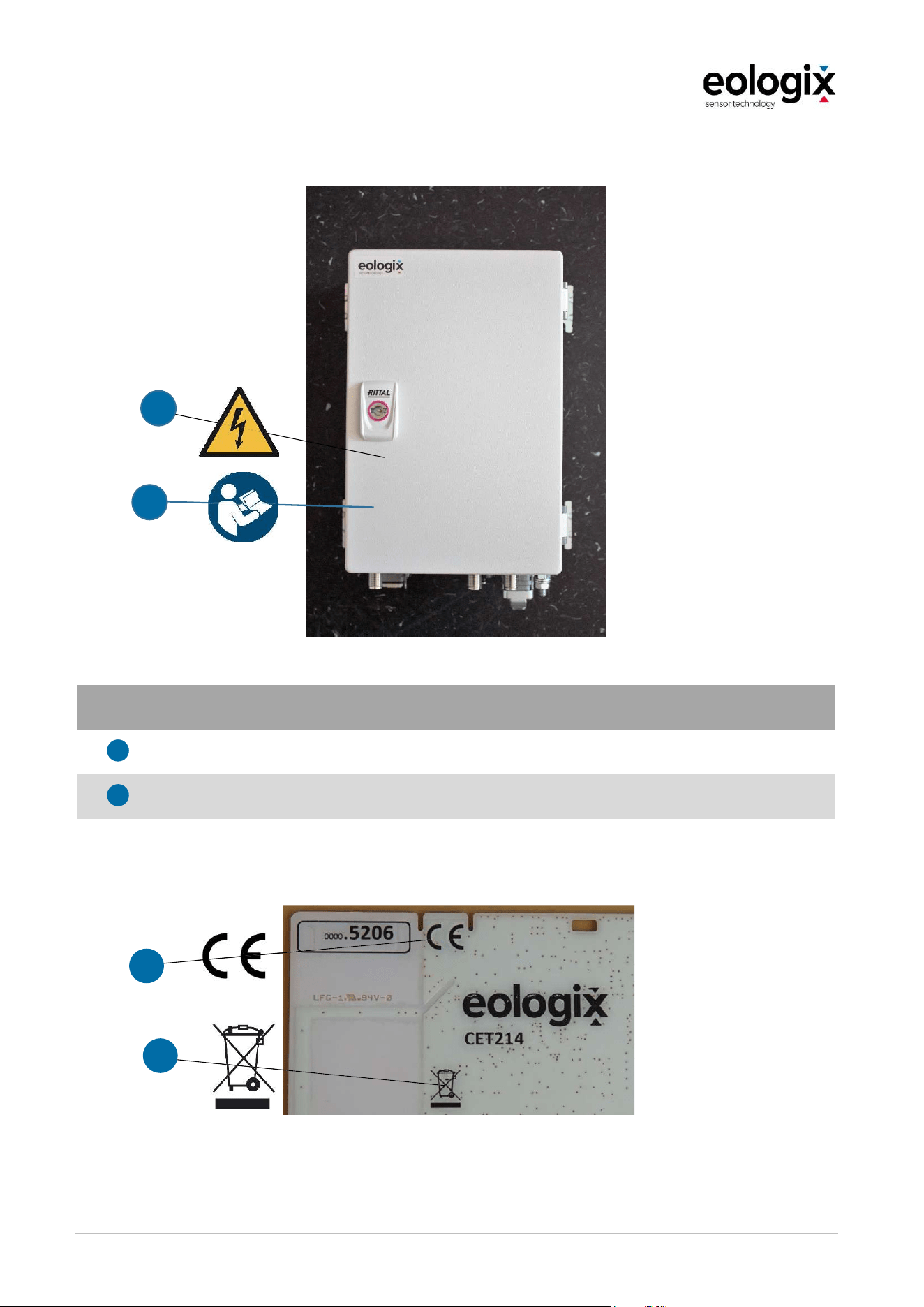
Warning, mandatory and prohibition signs on the product .................................................. 33
3.7.1
Notices on the base station ...................................................................................................... 34

OperationandServiceManual_V1_4_EN_eologix
© eologix sensor technology gmbh 2023
eologix.com 4 | 125
3.7.2
Notices on the sensor ................................................................................................................ 34
3.8
Training ............................................................................................................................................... 36
4
Structure ............................................................................................................................................. 37
4.1
Base station ....................................................................................................................................... 39
4.1.1
Function description base station............................................................................................ 41
4.1.2
Key features base station ......................................................................................................... 43
4.1.3
Technical specification base station ...................................................................................... 44
4.1.4
Connections.................................................................................................................................. 45
4.2
Sensor unit ......................................................................................................................................... 47
4.2.1
Key features sensor ................................................................................................................... 50
4.2.2
Technical specifications sensor ............................................................................................... 51
4.2.3
Function description ice measurement ................................................................................. 52
4.2.4
Function description temperature measurement ............................................................... 53
4.2.5
Function description pitch angle measurement ................................................................. 53
5
Installation .......................................................................................................................................... 54
5.1
Transport ............................................................................................................................................ 54
5.2
Storage ................................................................................................................................................ 54
5.3
Installation position of the base station ...................................................................................... 55
5.4
Installation of base station ............................................................................................................. 56
5.4.1
Cable connection ........................................................................................................................ 57
5.4.2
Mounting with wall brackets ..................................................................................................... 58
5.4.3
Mounting using clamps for mounting on H-profiles ........................................................... 59
5.4.4
Mounting the receiving antennas .......................................................................................... 60
5.5
Application positions of ice sensors ............................................................................................ 62
5.5.1
Application positions 9 ice sensors eologix:safe (9 ice sensors) ................................... 62
5.5.2
Application positions automatic restart ................................................................................. 63
5.6
Application of a sensor ................................................................................................................... 65
5.6.1
Requirements ............................................................................................................................... 66
5.6.2
Preparation for application ....................................................................................................... 67
5.6.3
Clean surface & apply Adhesion Promoter W9910 ............................................................ 69

OperationandServiceManual_V1_4_EN_eologix
© eologix sensor technology gmbh 2023
eologix.com 5 | 125
5.6.4
Unpacking ..................................................................................................................................... 70
5.6.5
Preparing ........................................................................................................................................ 71
5.6.6
Adjusting ......................................................................................................................................... 71
5.6.7
Adhering ........................................................................................................................................ 75
5.6.8
Inspection ...................................................................................................................................... 77
5.6.9
Sealing ........................................................................................................................................... 78
5.6.10
Documentation ............................................................................................................................ 79
5.7
Commissioning and test operation ..............................................................................................80
6
Operation ............................................................................................................................................. 81
6.1
Use ........................................................................................................................................................ 81
6.1.1
Ice detection .................................................................................................................................. 81
6.1.2
Automatic restart ......................................................................................................................... 82
6.1.3
Operation under ice load .......................................................................................................... 83
6.2
Handling .............................................................................................................................................. 84
6.3
Assessment of probability of failure ............................................................................................ 84
6.4
Read-out ............................................................................................................................................. 85
6.4.1
Login ............................................................................................................................................... 85
6.4.2
Main page ..................................................................................................................................... 86
6.4.3
Selection base station ................................................................................................................ 87
6.4.4
Time ................................................................................................................................................ 88
6.4.5
Sensor selection .......................................................................................................................... 89
6.4.6
Measured variables .................................................................................................................... 89
6.4.7
Temperature ................................................................................................................................ 90
6.4.8
Ice Signal ...................................................................................................................................... 90
6.4.9
Ice Warning ................................................................................................................................... 92
6.4.10
Ice Restart ..................................................................................................................................... 93
6.4.11
Update settings ........................................................................................................................... 94
6.4.12
Data download ............................................................................................................................. 95
6.4.13
Automatic data download ......................................................................................................... 96
6.5
Hardware and interface specification ......................................................................................... 97

OperationandServiceManual_V1_4_EN_eologix
© eologix sensor technology gmbh 2023
eologix.com 6 | 125
6.5.1
User interface ............................................................................................................................... 97
6.6
Faults/error recovery ....................................................................................................................... 97
7
Maintenance ...................................................................................................................................... 98
7.1
Cleaning .............................................................................................................................................. 98
7.2
Service ................................................................................................................................................. 99
7.2.1
Service manual base station .................................................................................................... 99
7.2.2
Service manual sensor .............................................................................................................. 99
7.2.3
List of spare parts ......................................................................................................................100
7.3
Corrective maintenance ................................................................................................................ 101
8
Decommissioning ...........................................................................................................................102
8.1
Switching off .................................................................................................................................... 102
8.2
Final closing down .........................................................................................................................102
8.3
Deinstallation ...................................................................................................................................102
8.3.1
Instructions for sensor removal ............................................................................................. 103
8.4
Disposal ............................................................................................................................................105
9
Attachment .......................................................................................................................................106
9.1
Declaration of EC-conformity base station .............................................................................. 106
9.3
Declaration of EC-conformity sensor unit ................................................................................108
9.5
Modbus Specifications ................................................................................................................... 110
9.5.1
Modbus Hardware/Interface Specifications ........................................................................ 110
9.5.2
Server and Document Versions .............................................................................................. 111
9.5.3
Document formatting notes ...................................................................................................... 111
9.5.4
Modbus Register Overview ..................................................................................................... 112
9.5.5
Data Volatility .............................................................................................................................. 113
9.5.6
Modbus Register Specifications: System Temperatures ................................................. 114
9.5.7
Modbus Register Specifications: Receiver RSSI values ................................................... 114
9.5.8
Modbus Register Specifications: Sensor Status ................................................................ 116
9.5.9
Modbus Register Specifications: Black Channel ................................................................117
9.5.10
Modbus Register Specifications: Static Info 32bit ............................................................120
9.5.11
Modbus Register Specifications: Static Info .......................................................................120

OperationandServiceManual_V1_4_EN_eologix
© eologix sensor technology gmbh 2023
eologix.com 7 | 125
9.5.12
Modbus Register Specifications: Sensor Info ..................................................................... 121
9.5.13
Modbus Register Specifications: System Errors ............................................................... 123
9.6
Register of units .............................................................................................................................. 124

OperationandServiceManual_V1_4_EN_eologix
© eologix sensor technology gmbh 2023
eologix.com 8 | 125
LIST OF FIGURES
Figure 1 Notices on the base station ........................................................................................................ 34
Figure 2 Notices on the sensor ................................................................................................................. 34
Figure 3 Overview of the sensor system ................................................................................................ 37
Figure 4 Overview transfer of measured data and interface integration (Ice application) ........ 38
Figure 5 Inside view base station .............................................................................................................39
Figure 6 Connections ...................................................................................................................................45
Figure 7 Relay contact (Front view) ..........................................................................................................45
Figure 8 Sensor components..................................................................................................................... 47
Figure 9 Display of the sensors mechanical flexibility ........................................................................ 48
Figure 10 Structure sensor unit..................................................................................................................49
Figure 11 Display ice thickness.................................................................................................................. 52
Figure 12 Connections ................................................................................................................................. 57
Figure 13 Example of a cabling (previous version) ............................................................................... 57
Figure 14 Mounting base station by means of the pre-mounted wall brackets (4 pieces) ....... 58
Figure 15 Required mounting holes for mounting by means of wall bracket............................... 58
Figure 16 Clamped connections ............................................................................................................... 59
Figure 17 Back side of the base station .................................................................................................. 59
Figure 18 Example of an installed base station (previous version) ................................................. 59
Figure 19 Rod antenna incl. antenna cable ........................................................................................... 60
Figure 20 Panel-antenna incl. antenna cable ....................................................................................... 60
Figure 21 Example of antenna mounting inside with clamps ............................................................ 61
Figure 22 Antenna mounting outside with clamps .............................................................................. 61
Figure 23 Application positions 9 sensors ............................................................................................ 62
Figure 24 Example of application positions eologix:restart (with 56m rotor blade length) ......63
Figure 25 Mounting on an existing installation .................................................................................... 65
Figure 26 Mounting of the sensors on the ground ............................................................................. 65
Figure 27 Mark assembly positions ......................................................................................................... 69
Figure 28 Prepare surface ......................................................................................................................... 69

OperationandServiceManual_V1_4_EN_eologix
© eologix sensor technology gmbh 2023
eologix.com 9 | 125
Figure 29 Apply Adhesion Promoter W9910 ......................................................................................... 70
Figure 30 Unpacking the sensor .............................................................................................................. 70
Figure 31 Removing the brown protective paper on the backside of the sensor ......................... 71
Figure 32 Adjusting the sensor ................................................................................................................. 72
Figure 33 Distance Trailing Edge in % - with an example of a sensor at 100%. ........................... 72
Figure 34 Wind rose on the sensor .......................................................................................................... 73
Figure 35 Alignment at the root of the rotor blade .............................................................................. 74
Figure 36 Adhering the sensor ................................................................................................................. 75
Figure 37 Apply assembly spray ............................................................................................................... 76
Figure 38 Remove protective tape from surrounding ......................................................................... 76
Figure 39 Strike out application solution ................................................................................................ 77
Figure 40 Inspection of the sensor .......................................................................................................... 77
Figure 41 Example of an applied sensor ................................................................................................. 78
Figure 42 Image documentation an example ....................................................................................... 79
Figure 43 Written Documentation Part 1: ID Sensor | Excel Sheet .................................................. 80
Figure 44 Login ............................................................................................................................................. 85
Figure 45 Main page ................................................................................................................................... 86
Figure 46 Select your base station .......................................................................................................... 87
Figure 47 Time .............................................................................................................................................. 88
Figure 48 Selecting a time period ........................................................................................................... 88
Figure 49 Sensor selection........................................................................................................................ 89
Figure 50 Temperature curve (example 1 sensor) .............................................................................. 90
Figure 51 Ice Signal ....................................................................................................................................... 91
Figure 52 Ice Warning ................................................................................................................................ 92
Figure 53 Ice Restart ....................................................................................................................................93
Figure 54 Data download .......................................................................................................................... 95
Figure 55 Data export as .csv ................................................................................................................... 95
Figure 56 Deinstallation ............................................................................................................................103

OperationandServiceManual_V1_4_EN_eologix
© eologix sensor technology gmbh 2023
eologix.com 10 | 125
VERSION
Version number Date Description Creator
0.1 09/10/2018 Draft 0 docu solutions
1.0 14/12/2018 Draft 1 docu solutions
1.1 17/01/2019 Draft 2 docu solutions
1.2 01/11/2019 Final version eologix
1.3 31/05/2022 New version DNV certificate
update
eologix
1.4 06/02/2023 Minor changes eologix
Translation of original operation and service manual.
Document created by:
docu solutions siegfried winterheller
Unterer Bründlweg 15, 8054 Graz
www.docusolutions.at

OperationandServiceManual_V1_4_EN_eologix
© eologix sensor technology gmbh 2023
eologix.com 11 | 125
1
INTRODUCTION
1.1
Contact information manufacturer
Should faults occur whose causes cannot be rectified with the help of this documentation,
please contact eologix sensor technology gmbh.
eologix sensor technology gmbh
Kratkystraße 2, 8020 Graz, Austria
Phone: +43 (0)316 931215 100
E-Mail: [email protected]
Homepage: www.eologix.com
All components of the product delivered by eologix sensor technology gmbh are identified as
follows:
1.2
Identification
The sensor system is made up of the base station and the wireless sensor.
Base station
Product
designation
eologix base station
Type designation BET214
Serial number XXXX.XXXX
Years of
manufacture
20XX
Wireless sensor
Product
designation
eologix wireless sensor
Type designation CET214
Serial number XXXX.XXXX
Year of
manufacture
20XX

OperationandServiceManual_V1_4_EN_eologix
© eologix sensor technology gmbh 2023
eologix.com 12 | 125
1.3
Marking
The product is clearly identified by the content of its label.
Base station
Sensor
CE marking acc.to Directive 2014/53/EU (Radio Equipment Directive).
1.4
Technical specifications
Technical specifications base station
Dimensions switch box (width x height x depth) 200 x 300 x 180 mm
Supply voltage
100
-
2
4
0
V AC
Control voltage 24 V DC
Technical specifications sensor element
Dimensions sensor (length x width x height) 360 x 254 x 0,3 to 2 mm
Voltage max. 3,2 V DC
Sensor supply Rechargeable button cell
Charging sensor supply Solar panel
Further technical data can be found in the documentation supplied and in chapters 4.1.3 for
the base station and 4.2.2 for the wireless sensor.

OperationandServiceManual_V1_4_EN_eologix
© eologix sensor technology gmbh 2023
eologix.com 13 | 125
1.5
Copyright
All documents are protected by copyright laws. Disclosure and reproduction of documents or
parts of the documents as well as sharing their contents are prohibited, unless explicitly
permitted. Any breach or infringement will result in liability for damages.
1.6
Liability
In accordance with European regulations, we provide a 2-year warranty for our product. This
operation manual serves the purpose of a fault-free operation of the product and is a
requirement for the fulfilment of any warranty claims.
The claims expire, for instance, in the even
Improper use
Incorrect safeguarding
Operation with defective or improperly installed safety devices and protective devices
Non-compliance with the instructions of this documentation
Use of spare parts other than original spare parts
Modifications without our written approval
Improperly carried out repairs
Cases of disaster, influences from extraneous elements and force majeure.t of:
Wear parts are not included in the scope of liability.
As a rule, the product's operational safety must always be inspected before the product is
initiated.
1.7
Content and purpose of this documentation
This documentation includes relevant information which makes it possible to work with and on
the product as safely as possible. Observing the instructions included in this document serves
the purpose of avoiding risks and damages to the product.
In addition to this operation manual, the applicable regulations for accident prevention and
environmental protection of the country of use and the installation site must be observed.

OperationandServiceManual_V1_4_EN_eologix
© eologix sensor technology gmbh 2023
eologix.com 14 | 125
Retaining this documentation
This document must be available near the product and must, in the latest version, always be
available for the users either electronically or as a print version. The manufacturer is obligated
to retain this documentation at least throughout the operating life of the product.
Effectivity
This manual is exclusively valid for the product with the marking CET214 and the name eologix
wireless sensor in combination with the product with the marking BET214 and the name eologix
base station. The product was placed on the market by eologix sensor technology gmbh and
transferred into the responsibility of the operator upon delivery.

OperationandServiceManual_V1_4_EN_eologix
© eologix sensor technology gmbh 2023
eologix.com 15 | 125
2
LIMIT OF USE
2.1
Intended use
The intended use of the sensor system consisting of base station and wireless sensors is ice
detection, temperature measurement and pitch angle measurement for wind turbines.
Icing and its layer thickness is detected by measuring the impedance on the surface. The
surface temperature is measured with an accuracy of ±0.25°C. The measurement data is
transmitted wirelessly to the base station with a range of at least 250m. The system consists
of a base station and several flexible sensors, which are applied on the rotor blades. The
sensors are glued to the blade surface (no drilling or similar - the rotor blade is not damaged)
and can also be retrofitted during regular inspections. The system measures icing at the point
where it happens. Observation of the effectiveness of existing anti- or de-icing solutions is
possible.
Detection of relative pitch angles is accomplished by measuring inertial sensing
(accelerations), which is an optional feature of the wireless sensor platform. This typically
features ±16g. The acquired data is transferred to servers of eologix sensor technology gmbh
during the application of the pitch angle measurement, which then calculate the relative pitch
angle by means of an algorithm and provide the determined value to the customer via a
dashboard.
A flexible solar cell ensures the energy supply, without light the function is maintained by
energy buffer for approx. 1000h.
The sensor is moulded on the blade erosion tape. Before installation, please carefully read the
installation information of 3M and prepare the blade surface accordingly. For more information,
visit the blade erosion tape manufacturer's website www.3M.com/wind for instructions on
applying 3M Wind Protection Tape 2.0/2.1 (W8750, W8751).
For compliance against DNV certificate, the number and position of sensors must be
coordinated with eologix (depending on turbine size, turbine type, application: "ice detection",
"ice free detection", "operation under ice load", "pitch angle measurement" etc.).
The product is built in accordance with the state of the art and recognized safety rules.
Nevertheless, its use may result in danger to life and health of the operator or third parties or
impairment of the product and other material assets. Intended use also includes observing the
operating instructions and complying with the maintenance requirements. Only use the
product when it is in perfect working order.
Use the product as intended and in a safety-conscious manner. If malfunctions or damage
occur that could impair safety, have them repaired immediately.

OperationandServiceManual_V1_4_EN_eologix
© eologix sensor technology gmbh 2023
eologix.com 16 | 125
2.2
Reasonably foreseeable misuse
Non-intended use can cause dangers for persons and damage to the product.
The wireless sensors may not be used on other components.
Deinstallation, manipulation or deactivation of the safety devices is prohibited.
It is prohibited to technically modify the product.
Original spare parts must be used.
Further, neither liability nor guarantee are assumed in the event of non-compliance with
the intended use.
The product may only be operated under the operating conditions specified in the
documentation.

OperationandServiceManual_V1_4_EN_eologix
© eologix sensor technology gmbh 2023
eologix.com 17 | 125
2.3
Limits of the product
The limits of use of the product are as follows:
Spatial limits
Installation at all kinds of wind power plants.
The system consists of various sensors and one receiving unit per turbine.
The sensors are adhered to the surface of the rotor blades
Temporal limits
The product is designed for outdoor use.
The operating life of the product is defined as 20 years.
Limits of use
The sensors can be applied anywhere on the rotor blades, but also on the nacelle or
the tower.
Further limits
Installation site of the base station: inside, dry, dust-free
The installation site of the base station must have an even and stable ground
Supply voltage 230V

OperationandServiceManual_V1_4_EN_eologix
© eologix sensor technology gmbh 2023
eologix.com 18 | 125
2.4
Target group and prior knowledge
This documentation is addressed to qualified personnel for commissioning, operation and
maintenance of the product. The commissioning, operating and maintenance personnel must
be chosen by the operator and must meet the following requirements:
General
Personnel which do not meet the requirement of being "qualified personnel" must acquire the
necessary qualification by means of appropriate trainings. It is the aim of such trainings to be
able to operate the product properly and as intended as well as to independently be able to
detect and avoid risks and dangers that might arise from the product.
Installation personnel
The independent installation of the product may only be carried out by qualified personnel
who
have been instructed regarding the installation of the product and who have read and
understood this operation and service manual,
have, in written form, been charged with the task of installing the product,
have fundamental electrical and mechanical professional knowledge.
In the case of application of the sensors at existing wind power plants, the respective
national safety and work regulations for rope access and positioning techniques apply.
To make it possible to acquire the necessary skills and knowledge, the operator must
implement the following measures:
Product training (written confirmation by the trained persons)
Regular safety briefing
Inspection, service, cleaning as well as corrective maintenance may only be carried out
by technical professionals with product-specific training as well as mechanical and/or
electrical training.
When choosing the personnel, the legal minimum age must be considered.
Professionals with product-specific training must be charged with and held liable for
planning and inspection of the activities.
Maintenance personnel
Maintenance activities may only be carried out by qualified personnel. The maintenance
personnel must have read this operation and service manual. Cleaning activities on the product

OperationandServiceManual_V1_4_EN_eologix
© eologix sensor technology gmbh 2023
eologix.com 19 | 125
may only be carried out by instructed personnel who have been informed about the dangers
that can arise from the product.
Operating personnel
The following physical qualities are considered requirements for operating the product:
User knowledge in the IT area, especially regarding the use and operation of Microsoft®
Windows operating systems,
may not be under the influence of addictive substances,
no pacemaker or implanted defibrillator
2.5
Principle
The product is a state-of-the-art product and meets the relevant safety and health regulations.
Nevertheless, dangers can arise in the event if maloperation or misuse.
to life and health of users or third parties
to the product and other material assets of the operator
to the efficient use of the product

OperationandServiceManual_V1_4_EN_eologix
© eologix sensor technology gmbh 2023
eologix.com 20 | 125
3
SAFETY
This documentation is structured in accordance with the effective EU regulations and includes
safety instructions. The operator of the product is responsible for ensuring that the installation
and operating personnel receive the necessary safety-relevant information and that they read
this documentation. The individuals are responsible for complying with the safety instructions.
This chapter includes a general introduction of the safety instructions as well as a description
of the warnings and safety instructions of the safety signs attached to the product. Important
information regarding accident prevention can also be found here.
Classification of notices
This document includes the following types of notices:
Safety instructions
Notices
Information
3.1
Safety instructions
This document includes safety instructions that must be observed for the sake of your own
personal safety, the safety of other personnel and for the sake of avoiding material damage.
Warnings and safety instructions inform the user about dangers that might result in minor,
major injuries, even death, or considerable material damage if the respective instructions are
not observed.
In the respective chapter, warnings inform about the dangers possible there. The structure of
warnings and safety instructions is identical.
Safety instructions as well as warnings are highlighted by means of a warning triangle and must
in any case be observed closely. They are shown as follows.

OperationandServiceManual_V1_4_EN_eologix
© eologix sensor technology gmbh 2023
eologix.com 21 | 125
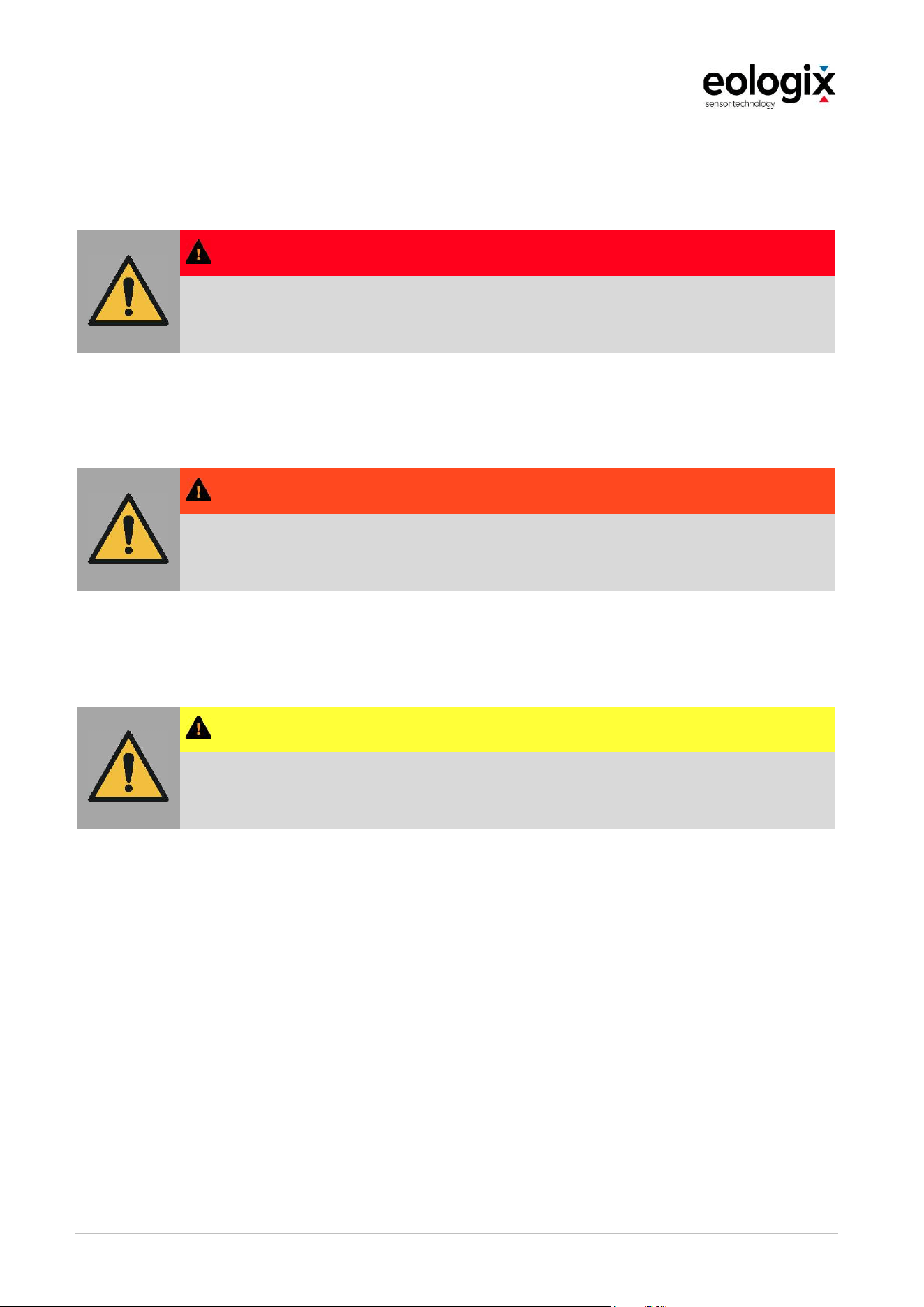
3.1.1
Structure of safety instructions
Operational warnings in the operation manual are structured as follows:
Warning,
mandatory or
prohibition
sign
SIGNAL WORD and CO LOR (GRAVITY OF DANG ER)
Type and source of danger
Possible consequences of non-observance
Measure 1 to prevent/avoid a danger
Possible further measures to prevent/avoid a danger
OperationandServiceManual_V1_4_EN_eologix
© eologix sensor technology gmbh 2023
eologix.com 22 | 125
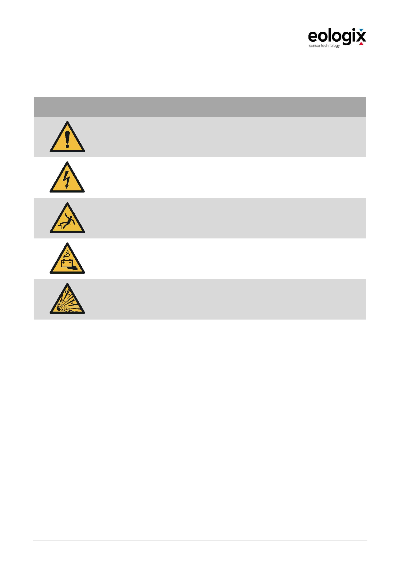
3.1.2
Signal words used in safety instructions
DANG ER
The word Danger with a red background indicates an imminent threat of danger.
Serious and permanent physical injuries or death can be the consequence.
W ARNING
The word Warning with an orange background indicates a possibly dangerous situation.
Serious injuries or death can be the consequence.
CAUTION
The word Caution with a yellow background indicates a possibly dangerous situation.
Minor injuries or damages to the product can be the consequence.
OperationandServiceManual_V1_4_EN_eologix
© eologix sensor technology gmbh 2023
eologix.com 23 | 125
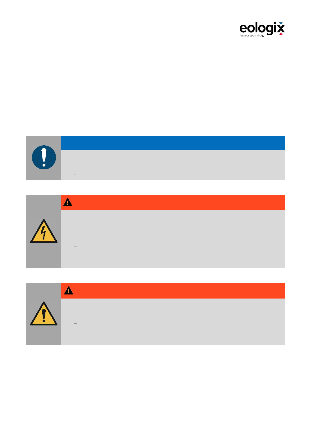
3.1.3
Warning, mandatory and prohibition signs used in safety instructions
Warning sign
Pictogram
Meaning Description
General warning sign W001
Warning of electric voltage W012
Warning of danger of falling W008
Warning of dangers due to charging batteries W026
Warning of explosive substances W002

OperationandServiceManual_V1_4_EN_eologix
© eologix sensor technology gmbh 2023
eologix.com 24 | 125
Mandatory sign
Pictogram
Meaning Description
General mandatory sign M001
Observe manual M002
Use ear protection M003
Use hand protection M009
Use head protection M014
Use safety harness M018
Disconnect before service or repair activities M021

OperationandServiceManual_V1_4_EN_eologix
© eologix sensor technology gmbh 2023
eologix.com 25 | 125
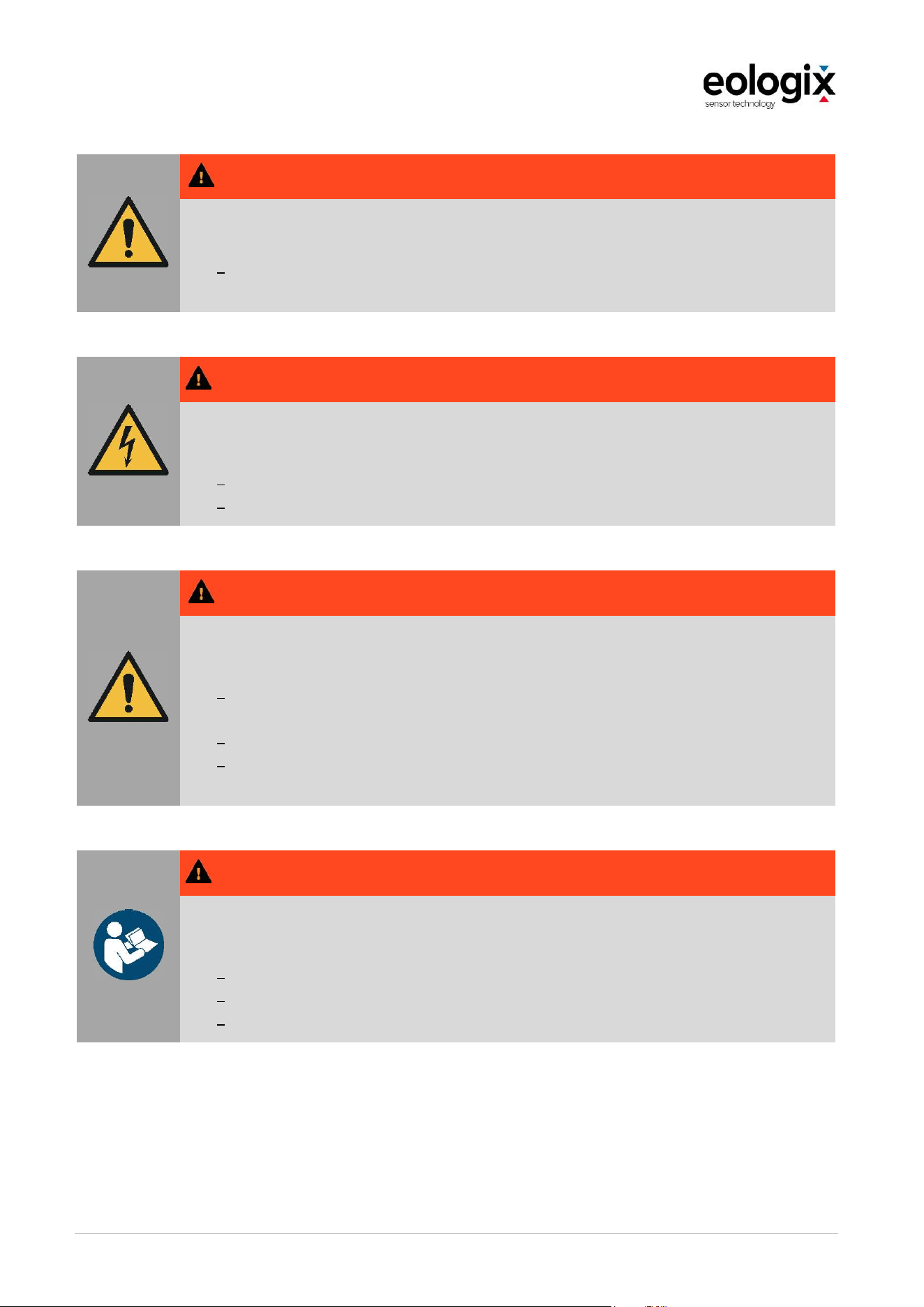
3.2
Notices
This document includes notices which are structured as follows. Notices include important
information regarding a product, use of the product or the respective part of the documentation
that attention is supposed to be drawn to and whose non-observance can have adverse
consequences which, as a rule, only lead to dangers for personnel or the product in individual
or exceptional cases.
Notices must in any case be carefully read and observed to ensure correct operation and
function.
Example:
N O T ICE
Possibly harmful situation.
Damages on the product or in their surroundings.
3.3
Information
Information included in this document is structured as follows. Information refers to additions
to a section in this manual or further information on the product, the use of the product or the
respective part of the documentation that attention is supposed to be drawn to and whose
observance is recommended because of a possible benefit.
Information should be read carefully and observed for the sake of optimum use and operation
of the product.
Example:
IN FO R M A TIO N
Refers to advice on use and other especially useful information that should be
considered before the operational steps.
OperationandServiceManual_V1_4_EN_eologix
© eologix sensor technology gmbh 2023
eologix.com 26 | 125
3.4
Residual risks
In spite of maximum diligence when constructing and building the product and in spite of
observing all safety-relevant facts, residual risks which have been evaluated by means of a risk
assessment can exist.
3.4.1
Base station
N O T ICE
Environmental damage due to improper disposal of packaging material.
Dispose of the packaging materials immediately and in an environmentally compatible way.
Recycle as much of it as possible.
W A R NIN G
Danger due to electric voltage.
Possibility of serious injuries or death when opening the base station.
Only qualified electricians may open the base station.
Installation and commissioning of the base station may only be carried out by qualified
electricians.
Only install or deinstall the base station when it is disconnected from the power supply.
W A R NIN G
Touchable voltage-carrying parts due to damages to the device. Danger of fire due
to
damages to the device. Serious injuries up to death due to electric shock or burns.
If the device, its casing or its insulation are damaged, do not operate the device
until it has been inspected and repaired by the manufacturer eologix sensor
technology gmbh.
OperationandServiceManual_V1_4_EN_eologix
© eologix sensor technology gmbh 2023
eologix.com 27 | 125
W A R NIN G
In the service rooms or at the wind turbine, there might be increased noise exposure.
Possible hearing damage.
In the event of increased noise exposure due to environmental noise, ear protection
must be worn.
W A R NIN G
Possible dangers due to electric voltage.
Serious injuries or death can occur when opening the base station.
Only the manufacturer or licensed qualified electricians may open the base station.
Disconnect the base station from the power supply before opening it.
W A R N U NG
Possible dangers due to electric voltage.
Serious injuries or death can occur while carrying out cleaning activities.
Do NOT use flammable substances in the device's surroundings to avoid causing a fire
or electric shock.
Ensure that the device is switched off.
Use neutral detergents. Using volatile substances like diluents or benzine damages the
outer surface of the device.
W A R NIN G
Possible dangers due to the consequences of human failure.
Serious injuries or death can occur in the event of improper use.
Read this operation and service manual before switching on the device.
Observe all safety instructions.
This operation and service manual must be retained!
OperationandServiceManual_V1_4_EN_eologix
© eologix sensor technology gmbh 2023
eologix.com 28 | 125
N O T ICE
Environmental damage due to improper disposal of waste electric equipment.
Return the base station to the manufacturer eologix sensor technology gmbh once
the operational lifetime has been exceeded or in the case of damages.
Recycle electrical waste.
W A R NIN G
Possible dangers due to loss of function
Observe all safety instructions and notices regarding installation, use and maintenance
included in this operation and service manual.
At least two antennae must be used to ensure the reliability for the transfer of data.
Lines may not be damaged, lines may not be pulled on, lines may not be crushed,
bending radii must be observed and the base station must be grounded properly.
The power supply must be connected or switched on as the last step.
OperationandServiceManual_V1_4_EN_eologix
© eologix sensor technology gmbh 2023
eologix.com 29 | 125
3.4.2
Residual risk sensor
W A R NIN G
Danger of falling. Danger due to falling down objects or bumping.
Possibility of serious injuries or death during sensor application.
The sensors may only be applied by trained personnel that is secured by fall protection.
The sensors may only be applied when the wind wheel is deactivated and cannot
rotate.
Wear a protective helmet.
Safety briefing with written confirmation.
Training and commissioning by manufacturer required.
W A R NIN G
Danger of falling. Danger due to falling down objects or bumping.
Possibility of serious injuries or death during maintenance, service and cleaning.
The sensors may only be serviced and cleaned by trained personnel who are secured
by fall protection.
The sensors may only be serviced when the wind wheel is deactivated and cannot
rotate.
Wear a protective helmet.
Safety briefing with written confirmation.
Training and commissioning by manufacturer required.
W A R NIN G
Possible dangers due to electric voltage or chemicals.
Serious injuries can occur when opening the sensor.
Modifications are not permitted.
The sensor may only be replaced entirely.
OperationandServiceManual_V1_4_EN_eologix
© eologix sensor technology gmbh 2023
eologix.com 30 | 125
W A R NIN G
Possible dangers due to fire or chemicals.
Serious injuries can occur in the event of improper handling of the battery cells.
Battery cells may only be replaced by the manufacturer eologix gmbh.
Do not open, burn or short-circuit batteries, do not expose
them to great heat or
wetness.
W A R NIN G
Possible dangers due to the consequences of human failure.
Serious injuries or death can occur in the event of improper use.
Read this operation and service manual before switching on the device.
Observe all safety instructions.
This operation and service manual must be retained!
N O T ICE
Environmental damage due to improper disposal of waste electric equipment.
Return the sensors to the manufacturer eologix sensor technology gmbh
once the
operational lifetime has been exceeded or in the case of damages.
W A R NIN G
Possible dangers due to loss of sensor function.
Observe all safety instructions and notices regarding installation, use and maintenance
included in this operation and service manual.
Observe the notices regarding application (adhering process, positions, etc.) of the
sensors included in this operation and service manual.
The sensors must be located at least one meter away from lightning receptors,
otherwise they might be damaged. Avoid areas on the rotor blade where the distance
between sensor and lightning arresters within the blade is less than 3 cm.

OperationandServiceManual_V1_4_EN_eologix
© eologix sensor technology gmbh 2023
eologix.com 31 | 125
3.5
General safety instructions and regulations
In general, the following safety regulations and obligations apply when handling the product:
The product may only be operated when it is clean and in immaculate condition.
It is prohibited to remove, change, bypass or bridge any protective, safety or monitoring
device.
It is prohibited to modify or change the structure of the product.
The operator must immediately be informed about faults or damages.
For any activity other than the intended use, the product must be disconnected from
the power supply.
Repairs may only be carried out by the manufacturer.
Only original spare parts may be used.
The safety instructions and operating instructions from the documentations of the used
components must in any case be observed.
Only instructed, trained and qualified persons may perform activities in the area of the
product.
The installation activities must be carried out in accordance with the installation plan
and must be documented.
OperationandServiceManual_V1_4_EN_eologix
© eologix sensor technology gmbh 2023
eologix.com 32 | 125
3.6
Personal protective equipment
Use your personal protective equipment in accordance with the local regulations resp. the
operator's regulations and always carry it with you.
In addition to the compulsory personal protective equipment, the following personal protective
equipment must be worn for the below-mentioned activities:
DA N G ER
Danger of falling
During installation activities at existing systems, there is a danger of falling when
working at height
Always wear fall protection when carrying out installation activities at height.
Only trained and briefed personnel may carry out installation activities at height.
W A R NIN G
Danger of being hit by objects or bumping
Possible consequences of non-observance
Always wear protective helmet during installation activities.
W A R NIN G
Danger due to noise
Possible hearing damage when working in areas with increased noise emission.
Always wear ear protection when working in loud areas.
CA U T IO N
Danger due to substances
Working with the adhesive tape and the edge sealer might lead to dermal injuries.
Always wear protective gloves when working with adhesives and edge sealers.

OperationandServiceManual_V1_4_EN_eologix
© eologix sensor technology gmbh 2023
eologix.com 33 | 125
3.7
Warning, mandatory and prohibition signs on the product
Safety instructions indicating dangers/residual risks are attached to the product. The
instructions of the safety signs on the product must be complied with under any circumstances.
Should the safety signs fade or be damaged throughout the product's operational lifetime, they
must immediately be replaced. The legibility and completeness must regularly be checked.
As soon as the signs are not recognizable or understandable at first glance, the product may
not be operated anymore until new signs have been attached to it.
Pictogram Meaning Description
Warning of electric voltage W012
Observe manual M002
OperationandServiceManual_V1_4_EN_eologix
© eologix sensor technology gmbh 2023
eologix.com 34 | 125
3.7.1
Notices on the base station
Figure 1 Notices on the base station
Pos. Location Description Dimensions
Base station Warning of electric voltage Height at least 25 mm
Base station Observe manual Height at least 25 mm
3.7.2
Notices on the sensor
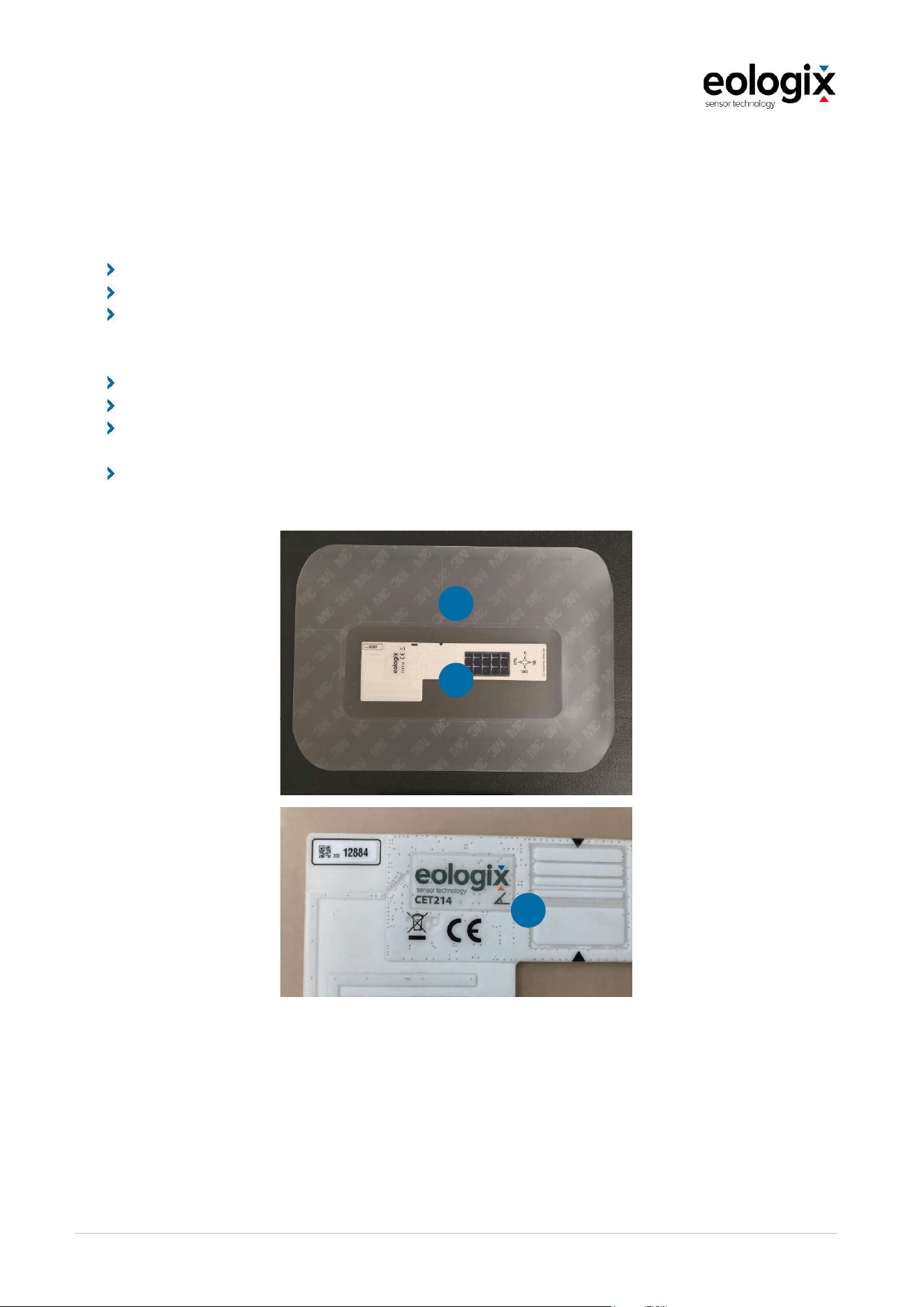
Figure 2 Notices on the sensor
1
2
1
2
2
1

OperationandServiceManual_V1_4_EN_eologix
© eologix sensor technology gmbh 2023
eologix.com 35 | 125
Pos. Location Description Dimensions
Sensor CE marking Height at least 5 mm
Sensor Do not dispose of waste electronic equipment as
domestic waste but return it to eologix
Height at least 5 mm
1
2

OperationandServiceManual_V1_4_EN_eologix
© eologix sensor technology gmbh 2023
eologix.com 36 | 125
3.8
Training
The installation and corrective maintenance personnel must be specifically trained regarding
their activities on the product. During training, the following aspects must be emphasized:
Close attention must be paid to safety instructions!
Information and warnings regarding residual risks required.
New personnel must be instructed before starting to work on and with the product.
Recurring training for the entire personnel is required.
Scope of training
The training measures include safety training, operation, servicing and corrective maintenance
of the product delivered, installed and commissioned by eologix sensor technology gmbh.
Training personnel
The initial training is, as a rule, provided by eologix sensor technology gmbh resp. by the
operator's correspondingly trained and qualified personnel. In-house training at the facilities of
the product's operator (i.e. training of new employees) may only be carried out by personnel
authorized and trained to do so by eologix sensor technology gmbh.
In addition, if the employee tasked with the staff training is unable to conduct the training or
resigns, the operator of the product is obligated to authorize and train at least one additional
employee for staff training.
If the initial training is not provided by eologix sensor technology gmbh, it is the operator's
responsibility to ensure proper training (in accordance with the scope of training outlined
above).
Training records
All trainings must be documented in a training record; in any case, the scope of training, the
trained persons and the person(s) providing the training must be included therein.
OperationandServiceManual_V1_4_EN_eologix
© eologix sensor technology gmbh 2023
eologix.com 37 | 125
4
STRUCTURE
The following figure provides an overview of the structure of the product.
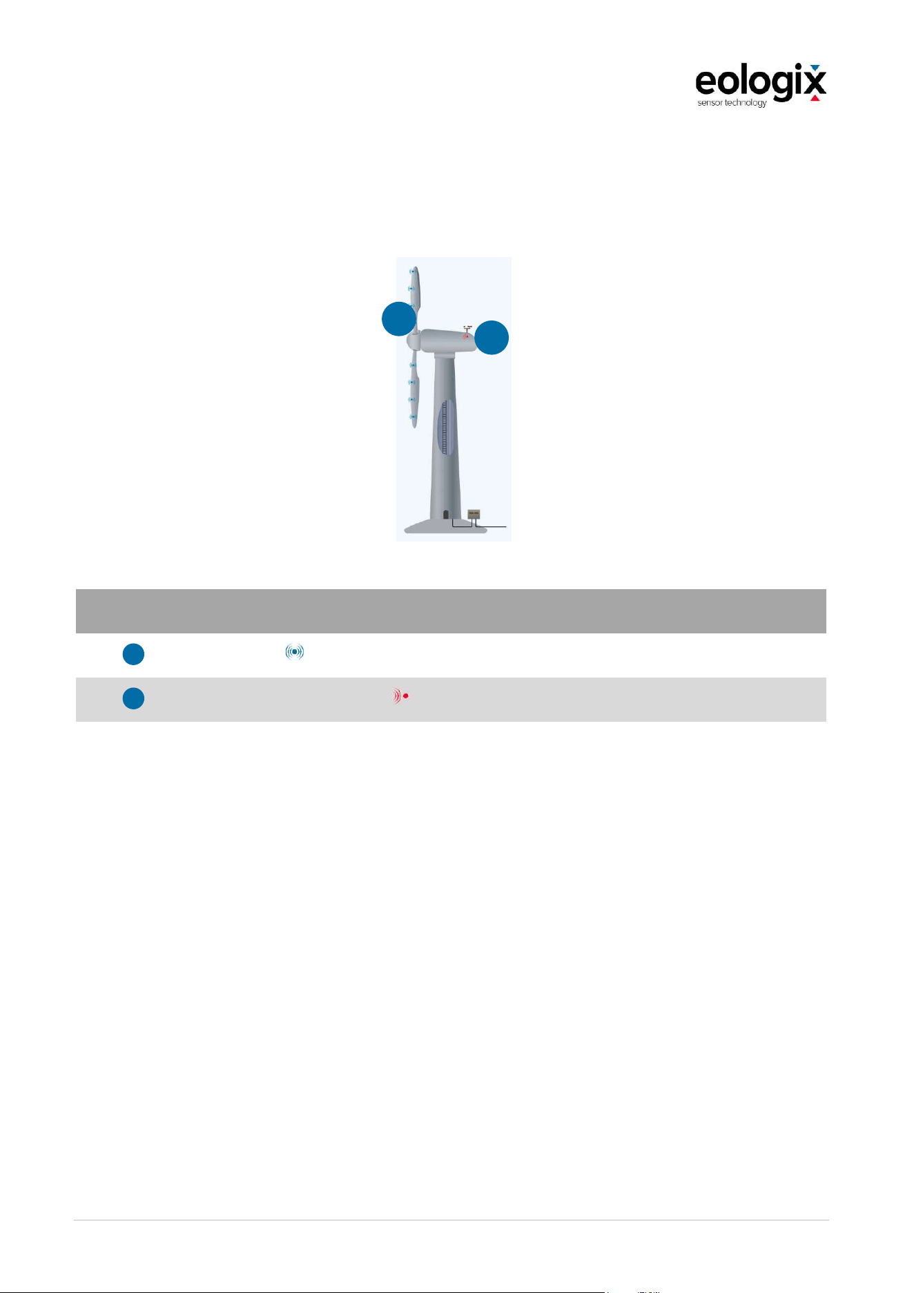
Figure 3 Overview of the sensor system
Pos. Component
Sensor units
Receiving unit (Base station)
The eologix sensor system is a blade-based measuring system. This means that a defined
number of sensors (depending on the application and, in some cases, the rotor diameter)
measure directly on the surface of the rotor blade. The sensors measure the temperature,
inertial data (optional) and capture the ice thickness directly at their application position, that
means at the surface of the rotor blades.
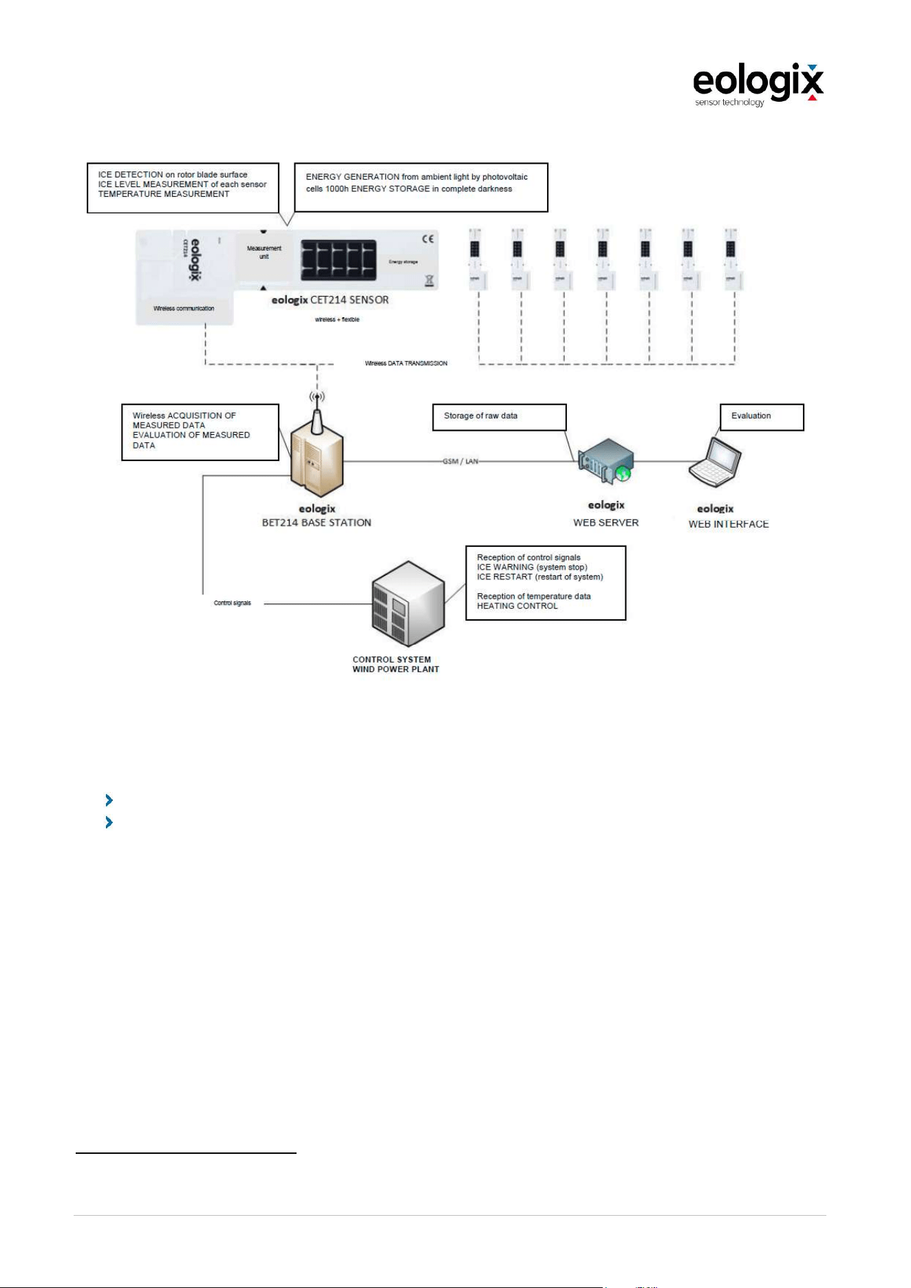
The measured data is transmitted wirelessly to a receiver (base station). The base station
receives the measurement data of all sensors, evaluates them and can be integrated via
various interfaces depending on the customer's requirements.
For the application of the relative pitch angle, the acquired inertial data is transmitted to servers
hosted by eologix, which use an algorithm to determine the relative pitch angles and then
transfer them to an online dashboard accessible to the customer. This means that a data
connection is also necessary for this application.
1
2
1
2
OperationandServiceManual_V1_4_EN_eologix
© eologix sensor technology gmbh 2023
eologix.com 38 | 125
Figure 4 Overview transfer of measured data and interface integration (Ice application)
The following applications can be realised with the system according to DNV component
certificate CCA-DNVGL-SE-0441-00526-01
1
:
Ice detection (meaning, i.e., system stop because of icing)
Ice-free-detection (meaning automatic restart of the wind power plant once it is ice-free
after a system-stop because of icing)
No control of the system is necessary for the pitch angle application, i.e. it is purely a monitoring
tool, so no DNV component certificate is required in this case - but in order to obtain an external
qualification, a certification process is also currently being carried out for the pitch angle
application.
1
Component Certificate DNV (Issued 2020-09-09 and valid until 2023-09-08)
OperationandServiceManual_V1_4_EN_eologix
© eologix sensor technology gmbh 2023
eologix.com 39 | 125
4.1
Base station
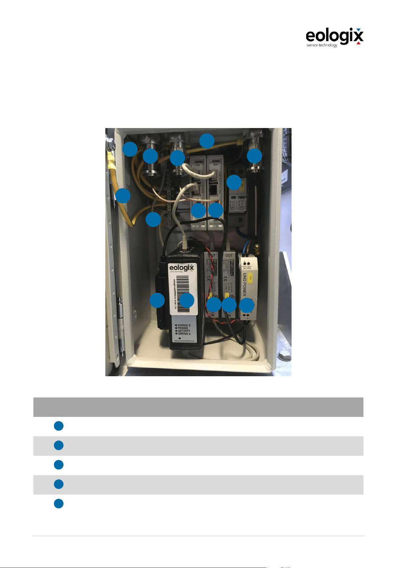
The following section provides an overview of the base station that can also be referred to as
receiving unit.
Figure 5 Inside view base station
Pos. Component
Relay or wireless communication modem
Earthing connection
eologix receiver
eologix IPC
Surge diverter ethernet
1
2
3
4
5
1
2
4
6
1
2
3
3
5
5
7
8
2
6
6

OperationandServiceManual_V1_4_EN_eologix
© eologix sensor technology gmbh 2023
eologix.com 40 | 125
Surge diverter antenna
Power supply unit 24 volt
Surge diverter power supply
6
7
8

OperationandServiceManual_V1_4_EN_eologix
© eologix sensor technology gmbh 2023
eologix.com 41 | 125
4.1.1
Function description base station
The base station receives the measurement data from the sensors by means of two antennas,
evaluates them and can be connected to the customer's system via various interfaces. The
antennas are mounted inside or outside the nacelle of the wind turbine, depending on its
condition. With an existing internet connection of the base station, it is also possible to store
the measurement data online (on own servers at the location of eologix in Graz, Austria) and
to display historical data by means of visualisation (see Chapter 6.4).
Possible interfaces
2 x or 3 x relay output (system status ok/not ok, ice stop yes/no, restart yes/no)
ModBus TCP/IP
CAN
RS485
Network interface 1 for connection to eologix online system
Network interface 2 for connection to OEM control or SCADA system
Further interfaces possible on request
The power consumption of the base station is typically 5 W (maximum 10 W).
Function principle
The eologix BET214 base station is a receiving unit for the eologix CET214 sensors and also
other compatible ice and temperature sensors. Typical installation positions of the base station
are in the nacelle or near the tower but are not limited (also e.g. sub-station or transformer
station). One base station is used per turbine.
The base station consists of the electrical cabinet and one or more receiving antennas,
depending on the designated installation. The base station antenna(s) receive(s) the signal
from the CET214 sensors (or compatible sensors). The base station stores and sends the data
to the eologix server for data processing or data usage for the customer. Furthermore,
switching signals are generated or various bus signals can be provided for turbine control.
The BET214 base station receives data packets from the sensors. The signals for the switching
relays are generated from these data packets:
System OK/ System NOT OK,
Ice-stop / NO ice-stop,
Restart / NO restart.
Optional: Inertial data (transmission to eologix server for further calculation of relative
blade angle errors)

OperationandServiceManual_V1_4_EN_eologix
© eologix sensor technology gmbh 2023
eologix.com 42 | 125
The data is also transferred online (to the eologix server) for further evaluation of the data. In
addition, various bus systems are supported by the system.

OperationandServiceManual_V1_4_EN_eologix
© eologix sensor technology gmbh 2023
eologix.com 43 | 125
4.1.2
Key features base station
BET214
Characteristics
Boundary
conditions
Minimum
value
Typical
value
Maximum
Value
Unit
Surrounding temperature During operation -40 60 °C
Humidity Non-condensing 0 95 % rh
Transmission range Linear distance 250 m
Lightning protection
devices in the electric
cabinet
Ethernet, antenna,
100-240 V AC
0 0B Zone
Measuring rate 0.5 1 2 1/min
Dimensions of the box L x W x H
200x180x
300
mm
Weight 6 kg
CE conformity
Passed
Yes
Insulation class
Electric cabinet
closed
IP55

OperationandServiceManual_V1_4_EN_eologix
© eologix sensor technology gmbh 2023
eologix.com 44 | 125
4.1.3
Technical specification base station
BET214
Characteristics
Boundary
conditions
Minimum
value
Typical
value
Maximum
Value
Unit
Power consumption 5 10 W
Input voltage AC 100 240 V
Frequency 50 60 Hz
Input voltage optional DC 12 24 28 V
Grounding cable Copper 16 mm²
Cable length Per antenna 10 m
Transmission relay Voltage 24 30 V
Transmission relay Power 2 A
Transmission relay Number 0 3 Pieces
Output 1 relay
OK/not OK
1=System OK
0=System not OK
0 1 -
Output 2 relay
Ice/no ice
1=NO ice-stop
0=ice-stop
0 1 -
Output 3 relay
restart
1=restart OK
0=NO restart
0 1 -
Digital bus system Standard Modbus TCP
Digital bus system Optional
CAN
RS45
Modbus RTU
Digital bus system Other On request
Online status-
monitoring system
Optional
Via Ethernet
or GSM
OperationandServiceManual_V1_4_EN_eologix
© eologix sensor technology gmbh 2023
eologix.com 45 | 125
4.1.4
Connections
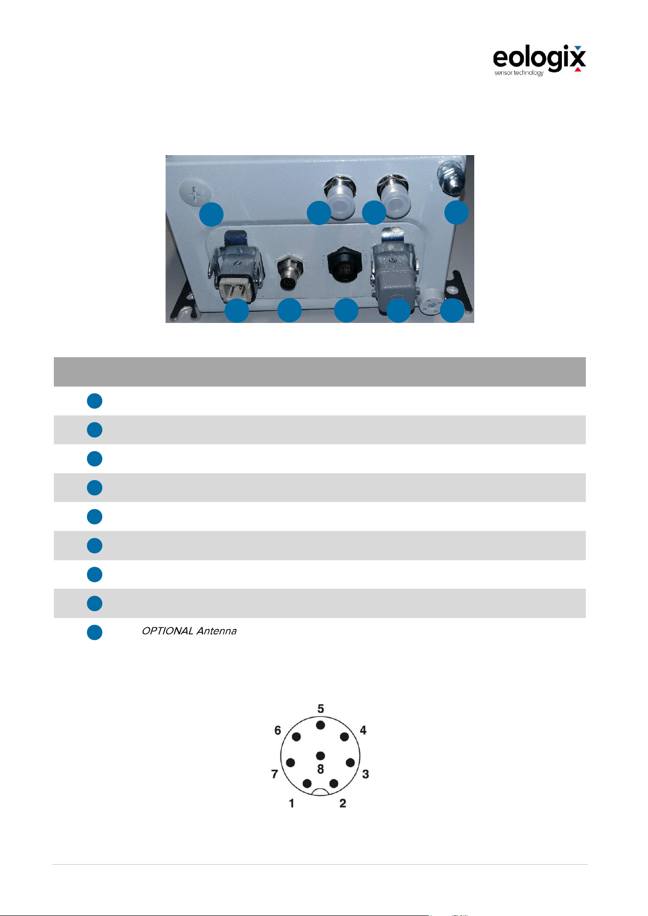
Figure 6 Connections
Pos. Description connection
Antenna 1
Antenna 2
Power supply
Relay
Ethernet
Modbus TCP
Condensation drain
Grounding
GSM Modem
4.1.4.1
Relay contacts
Figure 7 Relay contact (Front view)
1
2
3
4
5
6
7
8
9
1
2
3
4
5
6
7
8
9

OperationandServiceManual_V1_4_EN_eologix
© eologix sensor technology gmbh 2023
eologix.com 46 | 125
eologix offers three relay connection contacts. Basically, we recommend two relay connections
for the eologix:safe and three relay connections for the eologix:restart system. However, for
both systems a minimum configuration with the use of only one relay is possible.
The hardware is equipped with a relay interface with all relay contacts (as shown Figure 7 Relay
contact (Front view)) and depending on the number of connection points, the appropriate
software is then configured by us.
Overview of all relay contacts
PIN
Allocation
Description
1 (WH)
24 V 24 V from the system
2 (BN)
GND 0 V from the system
3 (GN)
Relay 1
COM
System OK, 24V to PIN 3
Connection between PIN 1 and 3, none
between 2 and 3
System NOT OK, 0V to PIN 3
Connection between PIN 2 and 3,
none
between 1 u. 3
4 (YE)
Relay 2
COM
NO ice-stop, 24V to PIN 4
Connection between PIN 1 and 4, none
between 2 u. 4
Ice-STOP, 0V to PIN 4
Connection between PIN 2 and 4,
none
between 1 u. 4
5 (GY)
Relay 3
COM
Restart OK, 24V to PIN 5
Connection between PIN 1 and 5, none
between 2 u. 5
NO restart, 0V to PIN 5
Connection between PIN 2 and 5,
none between 1 u. 5
6
(PI)
Not used
7 (BL)
Not used
8 (RE)
Not used
Function assignment - use of two relay connection contacts for eologix:restart
PIN
Allocation
Description
3 (GN)
Relay 1
COM
System OK, 24V to PIN 3
Connection between PIN 1 and 3,
none between 2 u- 3
System NOT OK, OV to PIN 3
Connection between PIN 2 and 3,
none between 1 u. 3
4 (YE)
Relay 2
COM
NO Ice-stop / Restart OK,
24V to PIN 4
Connection between PIN 1 and 4, none
between 2 u. 4
Ice-stop / NO restart,
0V to PIN 4
Connection between PIN 2 and 4,
none
between 1 u. 4
Function assignment - use of two relay connection contacts for eologix:restart
PIN Allocation
Description
4 (YE)
Relay 2 (!)
COM
System OK / NO STOP due ice / Restart
possible, 24V to PIN 4
Connection between PIN 1 and 4,
None between 2 and 4
System NOT OK / STOP due ice / NO
restart, OV no PIN 4
Connection between PIN 2 and 4,
None between 1 and 4
OperationandServiceManual_V1_4_EN_eologix
© eologix sensor technology gmbh 2023
eologix.com 47 | 125
4.2
Sensor unit
The patented sensor is flexible, wireless, has a self-sufficient energy supply and consists of the
following components:
Sensor unit (2 mm thick), adhesive foil (0.3 mm thick)
Radio interface for data transmission
Measuring surface for determining the electrical impedance of the surface (direct
measurement of the icing condition, icing with a thickness of less than 1 mm can be
detected)
Measurement of temperature with a resolution of ±0.25 °C
Flexible photovoltaic cell for energy generation from ambient light
Energy storage for back-up absolute darkness (a function of the sensor in absolute
darkness of more than 1000 h is guaranteed)
Optional: acceleration sensor for measuring inertial data
Figure 8 Sensor components
2
1
3
OperationandServiceManual_V1_4_EN_eologix
© eologix sensor technology gmbh 2023
eologix.com 48 | 125
Pos. Function
Sensor unit
Self-adhesive tape
Optional - In the version with acceleration sensors (possibility to measure inertial data) for
the pitch angle application, an "angle symbol" is also displayed on the sensor
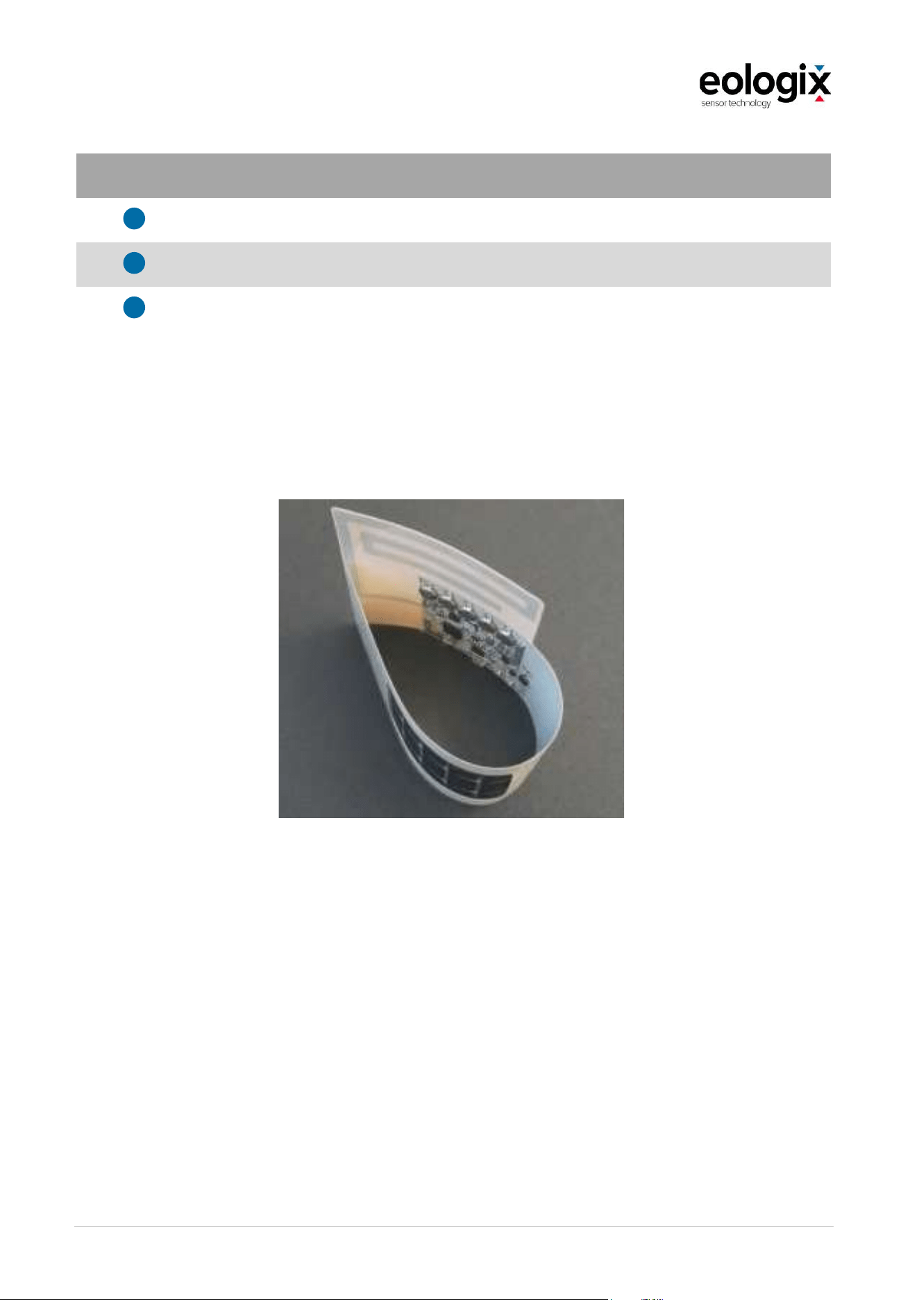
The sensor units can be mounted anywhere on the rotor blades, but also on the nacelle or
tower. Their flexible design makes them easy to install even on curvy surfaces. They are
delivered as a self-adhesive patch with an erosion protection film, and can be mounted within
minutes.
Figure 9 Display of the sensors mechanical flexibility
1
2
3
OperationandServiceManual_V1_4_EN_eologix
© eologix sensor technology gmbh 2023
eologix.com 49 | 125
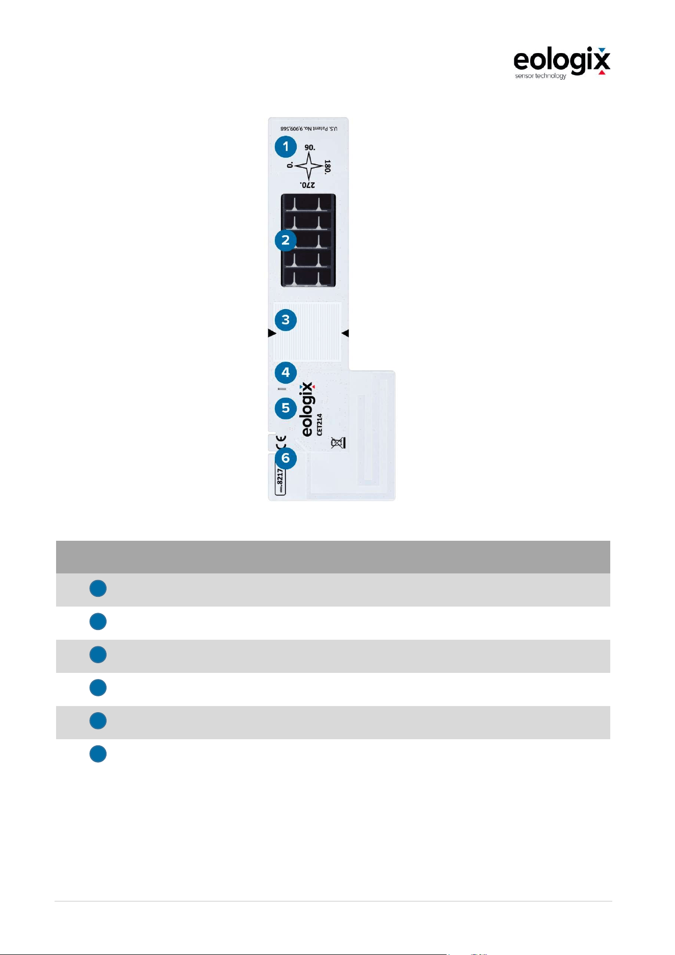
Figure 10 Structure sensor unit
Pos. Function
Energy buffer
Power supply by solar cells
Sensors for icing detection
Sensors for temperature measurement
Sensors for measuring inertial data (optional)
Module for wireless transmission of information
1
2
3
4
5
6

OperationandServiceManual_V1_4_EN_eologix
© eologix sensor technology gmbh 2023
eologix.com 50 | 125
4.2.1
Key features sensor
CET214
Characteristics
Boundary
conditions
Minimum
value
Typical
value
Maximum
value
Unit
Surrounding
temperature
During operation -30 60 °C
Humidity 0 100 % rh
Range of
transmission
Linear distance 250 m
Temperature Measuring range
-40 +85 °C
Temperature
Measuring
resolution
0.25 °C
Temperature
Measuring
accuracy
0.25 0.5 °C
Measurement
repetition rate
Set during
production
0.5 1 2 1/min
Minimum density
of ice
For detection 0.25 kg/dm³
Accelerations
(inertial sensors)
Optional
function
+-16g kg/dm³
Dimensions LxWxH Sensor 240x100x2 mm
Dimensions LxWxH
Tape (adhesive
tape)
360x254x0.3 mm
Weight Sensor 35 g
Weight Sensor + tape 80 g
Sensors per rotor
blade
Recommended
(depending on
application)
3 Pieces

OperationandServiceManual_V1_4_EN_eologix
© eologix sensor technology gmbh 2023
eologix.com 51 | 125
4.2.2
Technical specifications sensor
CET214
Characteristics
Boundary
conditions
Minimum
value
Typical
value
Maximum
value
Unit
Minimum
bending radius
50 mm
Recommended
storage
temperature
Ambient light >
1000 Lux
0 25 40 °C
Charge time
(after brief power
cuts)
AM1.5,
1000 W/m²
20°C
10 h
Operation time in
darkness
1000 h
Charge cycles
(calculated)
5 % discharge,
20°C
5000 1
Battery voltage 3.2 V
Battery capacity 68 mAh
Transmission
performance
1 10 mW
Average
transmission
performance
1 2 µW
Transmission
frequency (EU)
863 868 870 MHz
Transmission
frequency (North
America)
902 913 928 MHz
Materials
Adhesive material: 3M W8751 or W8750 wind blade protection tape, transparent
Other materials that come into contact with the blade surface: Potting compound for
electronics (silicone, polyurethane).
OperationandServiceManual_V1_4_EN_eologix
© eologix sensor technology gmbh 2023
eologix.com 52 | 125
4.2.3
Function description ice measurement
The eologix CET214 is a wireless sensor for measuring ice, temperature and inertial data. It
uses an SRD communication band powered by a photovoltaic cell as a standard power supply
in combination with accumulators (to bridge nights and longer icing times). The sensor unit is
completely isolated and requires no external power supply. The sensor controller has the
following two tasks:
Importing and processing the measured date and
wireless transmission of the data.
The ice detection is based on an integrated circuit for impedance measurement.
The base station BET214 or a BET214-compatible unit is required.
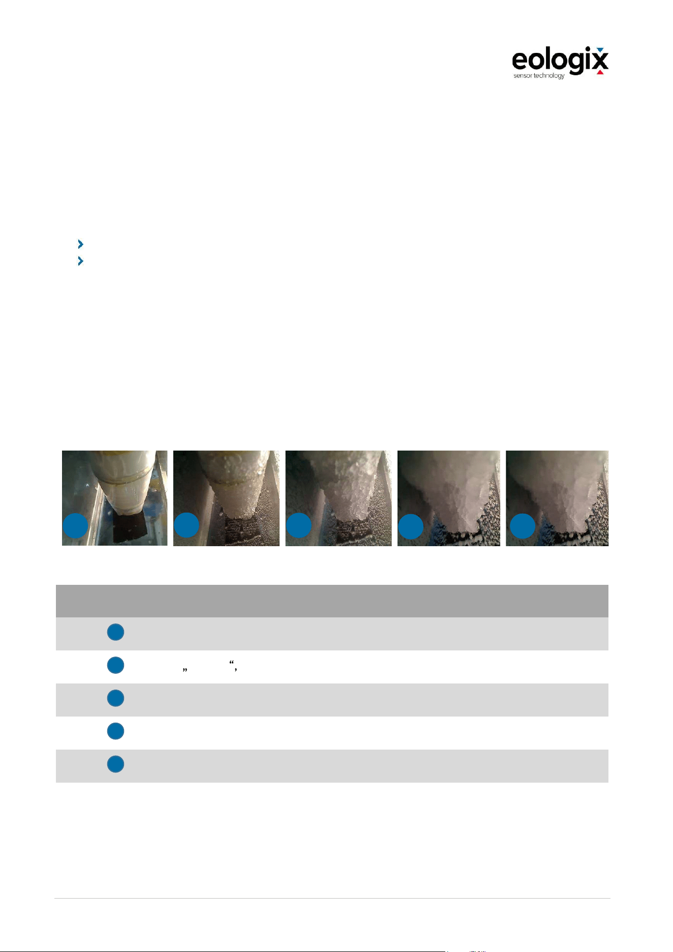
The following signal levels including their meaning are measured and output per sensor for ice
detection: The following images were created in an ice wind tunnel and show the
corresponding ice thickness per signal level as an example:
Figure 11 Display ice thickness
Signal Level Description
Free sensor surface
activity i.e. moistness, water, rime, etc. (no ice >1 mm)
Ice with a thickness of more than approximately 1 mm
Ice with a thickness of more than approximately 10 mm
Ice with a thickness of more than approximately 15 mm
1
2
3
4
5
1
2
3
4
5

OperationandServiceManual_V1_4_EN_eologix
© eologix sensor technology gmbh 2023
eologix.com 53 | 125
4.2.4
Function description temperature measurement
The surface temperature is measured by the sensor with an accuracy of ±0,25°C in the range
of -40°C bis +85 C.
4.2.5
Function description pitch angle measurement
The sensor system can also be used for relative pitch angle measurement. In contrast to
ground-based systems, the sensor system from eologix measures continuously.
There is a continuous measurement of the pitch angles, but because of different possible
occurrences (e.g. strong gusts, etc.) a result is only guaranteed once a week. For a successful
evaluation, the system must generally be in operation (no standstill and no spinning).
For installation and commissioning, an internet connection and a power connection are
required. If the customer cannot provide a LAN, the manufacturer can provide a SIM card as
an add-on (the customer must check the GSM reception at the location in advance - without
an internet connection (gondola network, SIM card, etc.) no system is possible, since the
calculation and evaluation of the data take place on the company's own secure server in Graz,
Austria.

OperationandServiceManual_V1_4_EN_eologix
© eologix sensor technology gmbh 2023
eologix.com 54 | 125
5
INSTALLATION
The installation of the sensor system is covered in the following chapters. This includes
requirements for transport, storage, the installation site, mounting and commissioning of the
base station and sensor.
The base station can be attached to a mounting location in the nacelle. See chapter 5.4
The sensor is delivered applied to a wind blade protection tape; by means of this tape and a
self-adhesive back side of the sensor, installation on the rotor blade is carried out at the same
time. Installation is possible at the manufacturer, on the construction site and also for already
erected wind turbines. See chapter 5.6
5.1
Transport
If the product is not delivered by eologix sensor technology gmbh, appropriate packaging must
be chosen for transport, as well as an appropriate transport company. The product
components must be packaged in appropriate transport containers and appropriately secured
for transport.
5.2
Storage
Regarding storage of the product, the following must be observed.
Depending on the ambient conditions, the product must be protected accordingly.
If necessary, the components must be treated accordingly to protect them against
corrosion damages.
Storage of the sensors
The sensors are exposed to light while in storage at the manufacturer's and are
therefore ready for use upon delivery.
Regarding storage at the operator's, it must be ensured that the batteries are not deeply
discharged by longer storage at a dark location.
If the sensors are stored at darkness for a period of time that exceeds the maximum
operation time at darkness, the sensors must be charged in conditions similar to
daylight or sunlight at least once for four hours within two weeks. This means that, in
the event of permanent storage, the charging process must be repeated at least every
two weeks for four hours. If in doubt, please contact eologix sensor technology gmbh.

OperationandServiceManual_V1_4_EN_eologix
© eologix sensor technology gmbh 2023
eologix.com 55 | 125
5.3
Installation position of the base station
The base station can be flexibly attached to any mounting location in the nacelle using four
clamp connections, screws or magnets. The two antennas are connected to the base station
via coaxial cables.
Transportation regulations must be observed!
Attachment of base station on firm, load-bearing ground
Connection of the cabling according to the plan
Installation site
The space required by the product must be taken into consideration in accordance with
the installation plan.
The place of installation must be suitable for the weight of the base station.
The connections of the electric lines must be taken into consideration.

OperationandServiceManual_V1_4_EN_eologix
© eologix sensor technology gmbh 2023
eologix.com 56 | 125
5.4
Installation of base station
W A R NIN G
During installation activities, improperly carried out activities can lead to additional
dangers.
If the product is not installed properly, dangers for persons can arise.
Installation works may only be performed by authorized and trained personnel.
When installing the base station, the following must be considered:
Before installing the base station, it must be inspected for completeness and transport
damages. Any deviations must immediately be reported to eologix sensor technology
gmbh! Subsequent complaints cannot be taken into consideration.
The base station must be installed on solid ground within the nacelle.
Installation on a suitable surface with suitable magnets, or
installation on a frame, rack or the wall using screws, or
installation on a frame or rack using clamped connections.
The BET214 base station and the corresponding antennae are individually configured for the
specific installation site. This includes:
Outside the turbine (in the transformer station or intermediate station)
Inside the nacelle (on an optional installation device or in an electric cabinet)
conductive material).
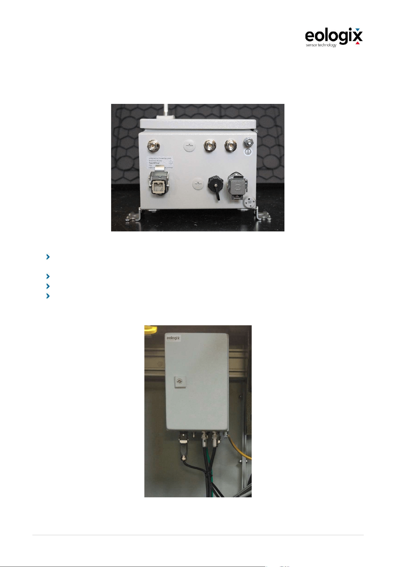
OperationandServiceManual_V1_4_EN_eologix
© eologix sensor technology gmbh 2023
eologix.com 57 | 125
5.4.1
Cable connection
Figure 12 Connections
The grounding of the base station must be connected to the grounding of the nacelle.
See Figure 13.
The two antennae are connected to the base station using coaxial cables.
Connection of the two corresponding data interfaces.
Connection of the power supply. Must be installed by a qualified electrician and
designed in accordance with the respective standards.
Figure 13 Example of a cabling (previous version)
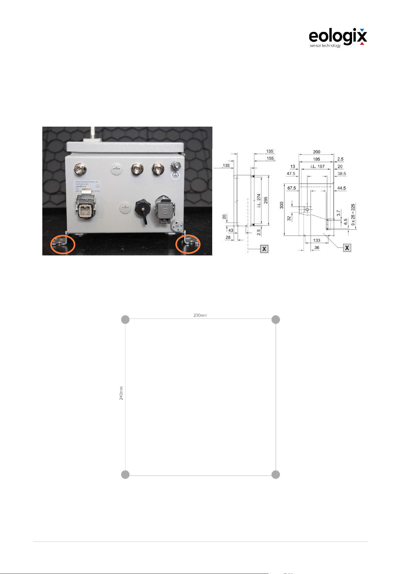
OperationandServiceManual_V1_4_EN_eologix
© eologix sensor technology gmbh 2023
eologix.com 58 | 125
5.4.2
Mounting with wall brackets
Necessary installation holes for the base station for 4xM8 screws in a rectangular grid
160mmx260mm.
Figure 14 Mounting base station by means of the pre-mounted wall brackets (4 pieces)
Required mounting holes for the base station for 4x M8 screws in a rectangular grid 230mm x
240mm.
Figure 15 Required mounting holes for mounting by means of wall bracket
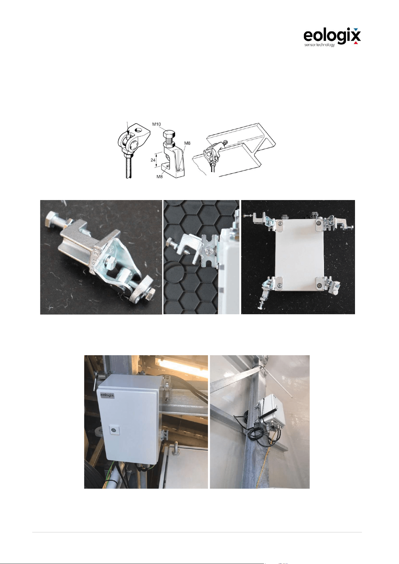
OperationandServiceManual_V1_4_EN_eologix
© eologix sensor technology gmbh 2023
eologix.com 59 | 125
5.4.3
Mounting using clamps for mounting on H-profiles
The option of mounting by using clamps on H-profiles is also available and is not part of the
standard equipment of the eologix base station.
The following pictures show the back of the base station with four clamp connections.
Figure 16 Clamped connections
,
Figure 17 Back side of the base station
This allows the base station to be mounted on the most commonly used H-profiles.
Figure 18 Example of an installed base station (previous version)
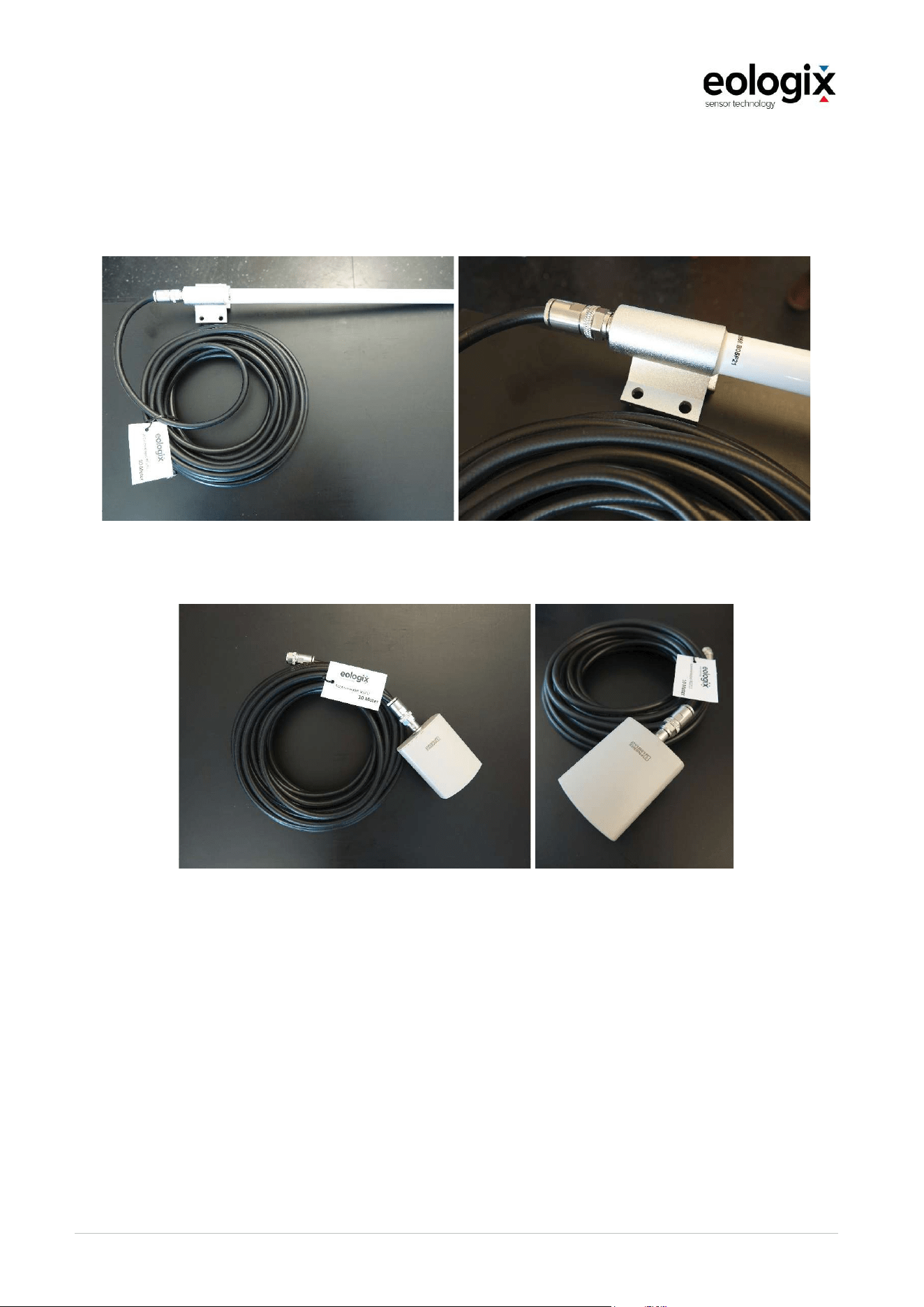
OperationandServiceManual_V1_4_EN_eologix
© eologix sensor technology gmbh 2023
eologix.com 60 | 125
5.4.4
Mounting the receiving antennas
For redundancy reasons, the base station is equipped with two receiving antennas.
The standard antennas are shown in the following figure.
Figure 19 Rod antenna incl. antenna cable
Figure 20 Panel-antenna incl. antenna cable
The type and mounting location of the antennas depend on several factors such as the material
of the nacelle outer wall, turbine diameter, etc. and differ depending on the turbine type.
The mounting location of the antennas is defined by eologix in cooperation with the customer
on a project-specific basis. The following illustrations show examples of antenna installation.

OperationandServiceManual_V1_4_EN_eologix
© eologix sensor technology gmbh 2023
eologix.com 61 | 125
Figure 21 Example of antenna mounting inside with clamps
Figure 22 Antenna mounting outside with clamps
Antenna
Clamps
Antenna
Clamps
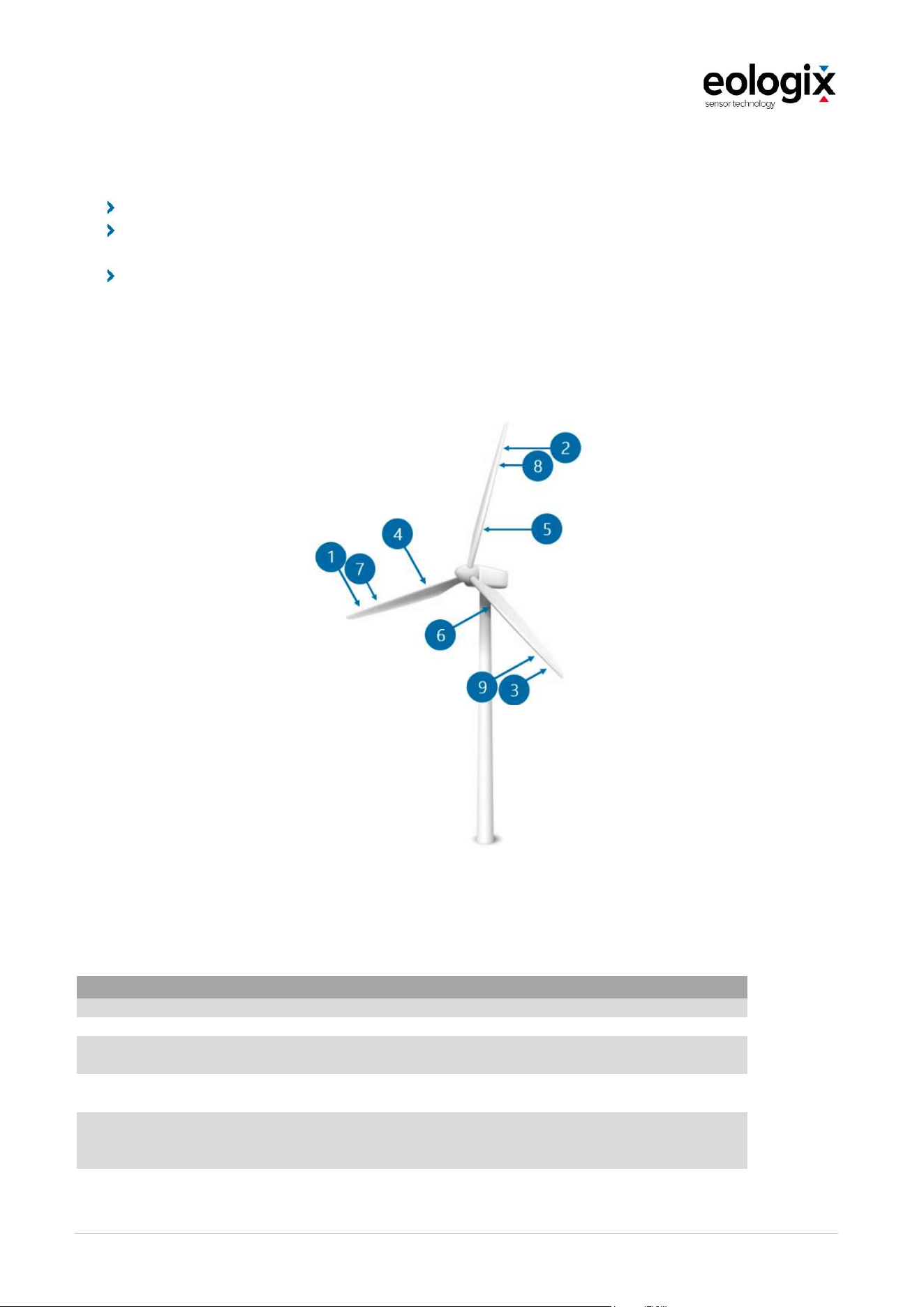
OperationandServiceManual_V1_4_EN_eologix
© eologix sensor technology gmbh 2023
eologix.com 62 | 125
5.5
Application positions of ice sensors
It must be ensured that the mounting location is flat and free of contamination.
As a rule, the product is applied by qualified personnel from eologix sensor technology
gmbh.
Requirements for the mounting location are coordinated in advance with the operator,
the original equipment manufacturer (OEM), etc.
5.5.1
Application positions 9 ice sensors eologix:safe (9 ice sensors)
Figure 23 Application positions 9 sensors
The number of sensors on the eologix:safe does not depend on the rotor blade length. The
positions of the sensors are shown as follows:
eologix:safe (9 sensors)
Tolerance of all length specifications ±1 meter
All sensors (1-9) Leading edge
6 sensors (sensor 1/7/2/8/9/3 in the figure 23)
at the three blade tips
Distance from root: > 70% of blade length
3 sensors (sensor 4/5/6 in the figure 23) at
the three blade roots
Distance from root: < 20% of blade length
Conditions for redundancy
Operation for ice detection as long as two
sensors are active at the blade tip and one
sensor is active at the root
Distance lightning receptors
Distance to each lightning receptor must be
at least 1 m
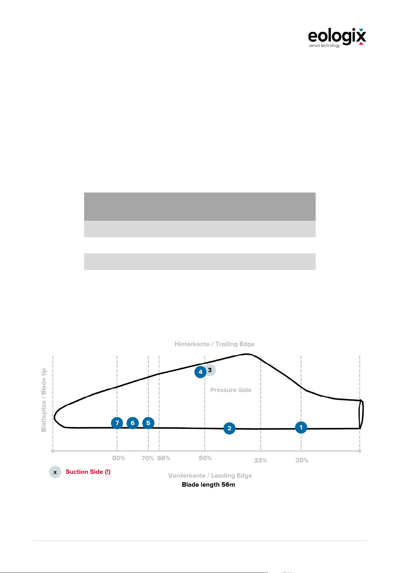
OperationandServiceManual_V1_4_EN_eologix
© eologix sensor technology gmbh 2023
eologix.com 63 | 125
5.5.2
Application positions automatic restart
In this mode, another signal (in addition to the "stop" signal) is generated according to the
algorithm as per the DNV component certificate, which signals the system to restart
automatically after a stop due to icing. I.e. the system detects when there is no more ice on the
rotor blades of the turbine and signals the turbine to restart it.
In an eologix:restart system, the necessary positions for ice detection are covered several
times. This means that every eologix:restart system is also suitable for the ice detection
function. The number of sensors used in the eologix:restart system depends on the size of the
wind turbine. The following system size (i.e. number of sensors) is used depending on the
blade length:
Rotor blade length in m
Number of sensors per
turbine
<= 30 m 18
> 30 m and <= 60 m 21
> 60 m and <= 90 m 24
> 90 m 27
Figure 24 Example of application positions eologix:restart (with 56m rotor blade length)

OperationandServiceManual_V1_4_EN_eologix
© eologix sensor technology gmbh 2023
eologix.com 64 | 125
Automatic restart
(eologix:restart)
one blade as example shown, all three rotor blades have
to be equipped symmetrically) using the example of 21
sensors for a system with a blade length of 56 m
Tolerance of all length specifications ±1 meter
Conditions for redundancy
Operation to detect ice (no automatic restart) as long as 2 sensors at
the tip and 1 sensor at the root are active
Distance of lightning receptors Distance to each lightning receptor must be at least 1 m
Number of sensors In detail as shown in Chapter 6.1.2
Sensor 1, 2
Leading Edge (100% Distance trailing edge);
Distance from the root 20% and >40%
Sensor 3
Suction side (10% Distance trailing edge)
Distance from the root 50%
Sensor 4
Pressure Side (10% Distance trailing edge)
Distance from the root 50%
Sensor 5-7
Pressure Side (>90% Distance trailing edge)
Distance from the root >70%

OperationandServiceManual_V1_4_EN_eologix
© eologix sensor technology gmbh 2023
eologix.com 65 | 125
5.6
Application of a sensor
The sensor is delivered applied to wind blade protection tape; by means of this tape and a
self-adhesive back side of the sensor, application on the rotor blade is carried out at the same
time. The wind blade protection tape by 3M (W8751 resp. W8750) that is used has been used
for more than ten years in wind power to protect the leading edge.
The sensors can be applied by the manufacturer, on the construction site (before lifting the
blades) as well as at existing systems (retrofitting by means of manlift or industrial climbers).
Application can be carried out by the customer themselves. Training by eologix necessary.
Figure 25 Mounting on an existing installation
Figure 26 Mounting of the sensors on the ground

OperationandServiceManual_V1_4_EN_eologix
© eologix sensor technology gmbh 2023
eologix.com 66 | 125
When applying the sensors, the following must be considered:
Before applying the sensors, they must be inspected for completeness and transport
damages. Any deviations must immediately be reported to eologix sensor technology
gmbh! Subsequent complaints cannot be taken into consideration.
The product must be attached to a clean, firm and even surface.
Position the unpacked product in accordance with the installation plan.
The guidelines of the following installation plan must be observed.
5.6.1
Requirements
Required qualifications of installation personnel
Experience in the installation of blade erosion tape. For more information, visit the
manufacturer of the blade erosion tape website www.3M.com/wind for instructions on the
application of 3M Wind Protection Tape 2.0/2.1 (W8750, W8751).
If the sensors are applied to already erected wind turbines, the respective national safety and
work guidelines for rope access and positioning techniques apply. Furthermore, we
recommend a short consultation with an eologix service contact (to be reached via
[email protected]) to clarify any open questions and/or to receive useful tips.
N O T ICE
The temperature of the rotor blade should be 16° C or higher to ensure proper adhesion of the
tape.
If in doubt regarding methods to warm up the rotor blade, contact the manufacturer eologix
sensor technology. It must be ensured that the rotor blade is not damaged while it is warmed
up
Ground
No tears or damages
No dirt
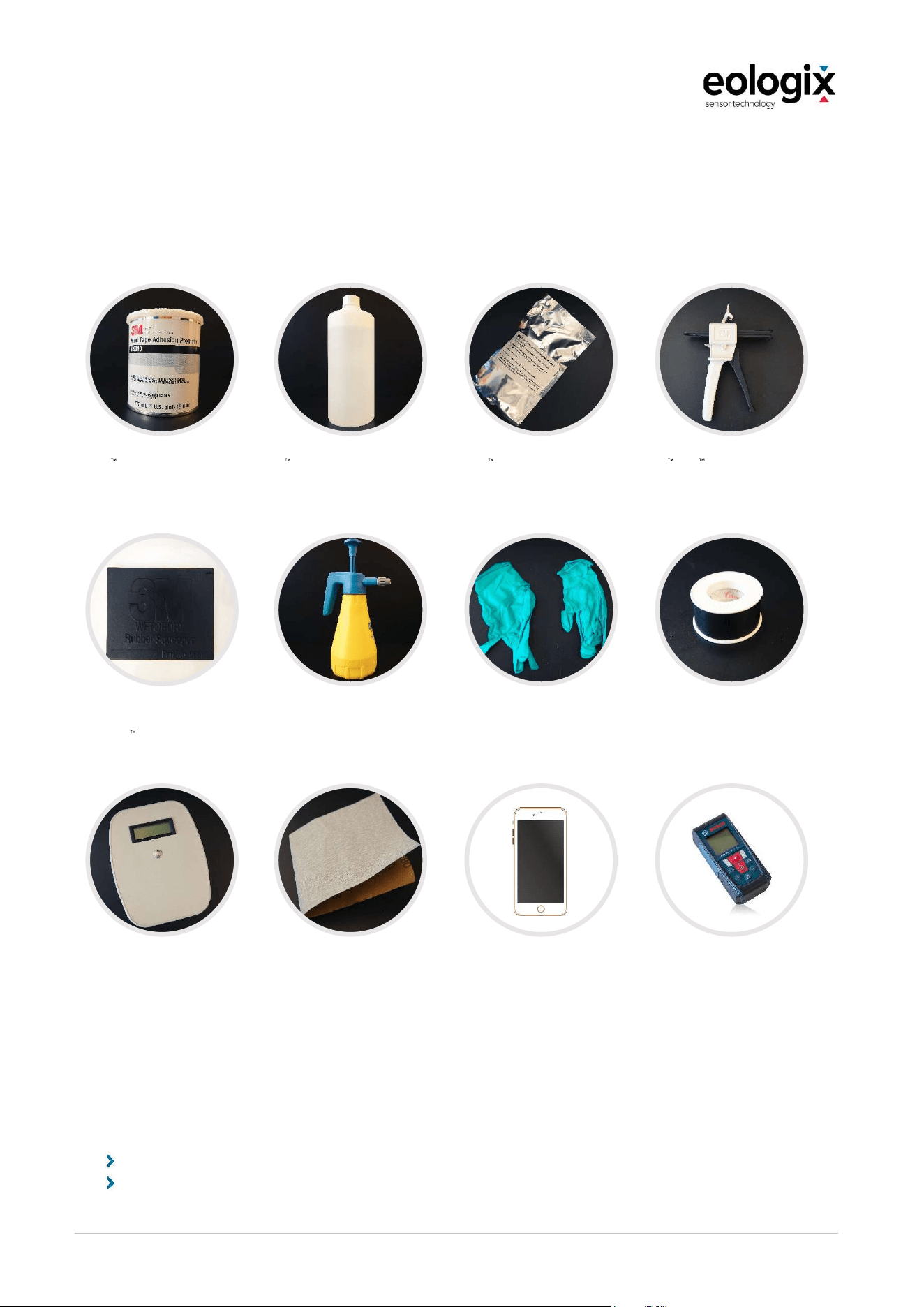
OperationandServiceManual_V1_4_EN_eologix
© eologix sensor technology gmbh 2023
eologix.com 67 | 125
5.6.2
Preparation for application
Preparation for application by manufacturer or before lifting in warm surroundings:
Make sure to have all the following required tools ready before starting the mounting of the
sensors:
Adhesion Promotor
(3M Wind Tape Adhesion
Promotor W9910 and
additionally paper wipes,
wipes and adhesive tape)
Mounting spray
(3M Application Solution Spray
75% water + 25% Isopropyl)
Edge sealing
(3M Wind Protection Tape
Edge Sealer W2600 and
EPX mixing nozzles, as well
as a plastic spatula)
Applicator
3M EPX Applicator for edge
sealing
Spatula Wet or Dry
Rubber Squeegee
(3M
Part.No 05517)
Pressure sprayer
min. 0.5l
Rubber gloves
Disposable; Nitrile rubber
Insulating tape
for marking the mounting positions
Manual reader
(provided on request by
eologix)
Sandpaper
(Grit 250-500)
Smartphone or
camera
with good resolution for
image documentation
(more on this in the chapter
"Documentation")
Distance measuring device
or rolling measure
for determining the mounting
positions
Preparation rope installation
For installation by industrial climbers, the following tools and materials are necessary:
Personal protective equipment against falling
Disposable protective gloves nitrile rubber
OperationandServiceManual_V1_4_EN_eologix
© eologix sensor technology gmbh 2023
eologix.com 68 | 125
Sanding sponge or sanding paper (grit 250 500)
Cleaning cloths, clean and lint free, at least 1 piece
Rubber squeegee (3M squeegee gold or blue), 2 pc.
Application spray
(3M Application Solution Spray, 25% isopropyl mixed with 75% water), 3l
Infrared thermometer, 1 pc.
Spray bottle, 2 pc.
Paper roll, 1 pc.
Promotor (3M Adhesion Promotor W9910) 1 can
Brush, 2 pcs. (to apply the Adhesion Promotor W9910)
Roller, 1 pc. (to evenly apply the sensor), 1 pc.
Edge sealer (3M Edge Sealer W2600), 3 packets
Applicator (3M Applicator EP-
Plastic body scraper, thin, > 5 pcs (to apply and smoothen the edge sealer)
Handheld indicator eologix handheld indicator (to inspect the eologix sensors), 1 pc.
Spare batteries for handheld indicator, 4 pcs.
Camera for documentation
Refuse bags, > 3 pcs.
Sensors
The following documents are provided by eologix:
Mounting positions of the sensors (PDF) - please print out in advance
Excel file for collecting the sensor IDs (part of the written documentation)
Handheld reader (provided by eologix)
ev. File for positioning the sensors (only necessary for the pitch angle application)
N O T ICE
Please observe the associated instructions for positioning the sensors
for the pitch angle
application "eologix_align_Positioning_the_Sensors_vX.X.pdf" for proper installation and
correct position in the latest valid version!
N O T ICE
If the sensor has been stored in the dark for a longer period of time (e.g. during transport),
the sensor should be exposed to direct sunlight or artificial light similar to daylight for at
least 1 hour before installation.
The sensor must be checked for proper functioning with the handheld reader before
installation.

OperationandServiceManual_V1_4_EN_eologix
© eologix sensor technology gmbh 2023
eologix.com 69 | 125
Step 1: Mounting positions.
Please measure the position of the sensors to be mounted as specified in the turbine-specific
document with mounting positions provided by eologix (depends on system type and
application!) and mark them on the rotor blade, e.g. using a piece of insulating tape. Ensure
that the minimum required distance to the lightning receptors is maintained. (as seen in
Chapter 5.5).
Figure 27 Mark assembly positions
5.6.3
Clean surface & apply Adhesion Promoter W9910
Step 2: Clean surface and apply adhesion promoter
The marked mounting surfaces must be cleaned of dirt, dust, grease or silicone. If necessary,
use sandpaper (grit 250 - 500) to smoothen the surface. Any cracks must be filled beforehand
to create a suitable base surface before the sensors can be applied.
Figure 28 Prepare surface
Apply a thin film of 3M Wind Tape Adhesion Promotor W9910 to the intended adhesive area
of the sensor with a wipe or brush (alternative: use "3M Wind Tape Adhesion Promotor W9910
Wipes"). The Adhesion Promoter W9910 is necessary to ensure the initial adhesion of the 3M
Wind Tape. After applying the promotor to the cleaned and sanded surface, it must dry for at
least 10 minutes before the sensor can be applied.
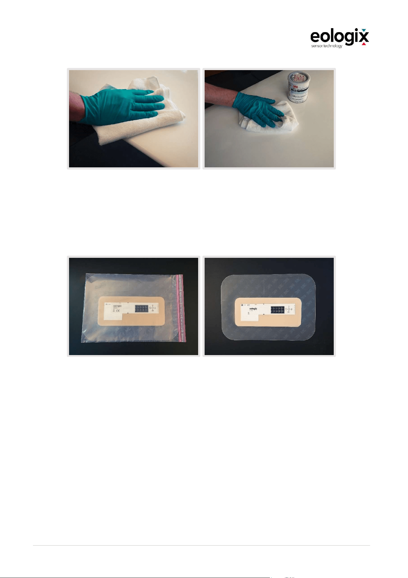
OperationandServiceManual_V1_4_EN_eologix
© eologix sensor technology gmbh 2023
eologix.com 70 | 125
Figure 29 Apply Adhesion Promoter W9910
5.6.4
Unpacking
Step 3: Unpacking
In the next step, please remove the sensor from the packaging as shown.
Figure 30 Unpacking the sensor
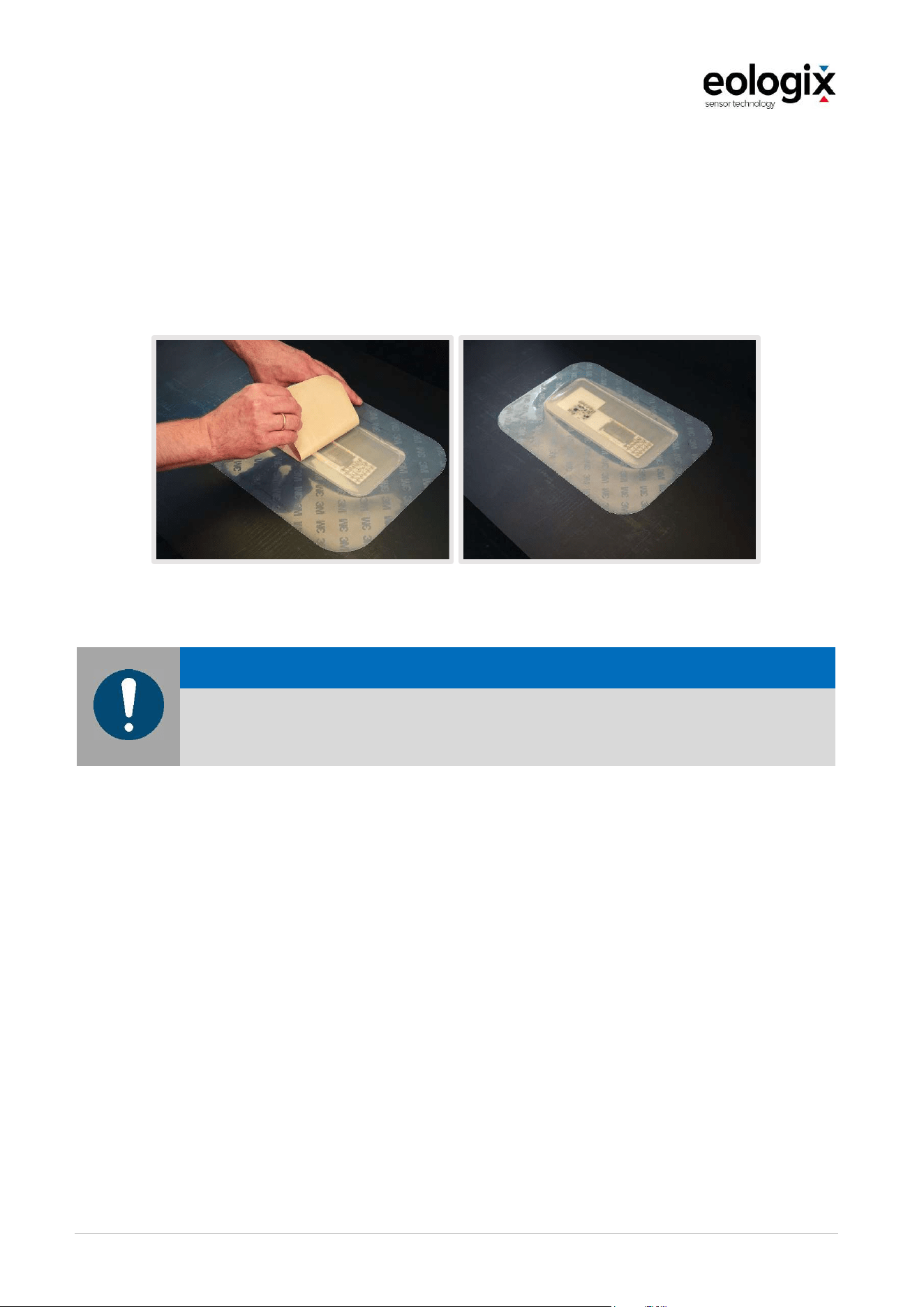
OperationandServiceManual_V1_4_EN_eologix
© eologix sensor technology gmbh 2023
eologix.com 71 | 125
5.6.5
Preparing
Step 4: Removing the brown protective paper
In step four, carefully remove the brown protective paper from the back of the sensor. Be
careful not to inadvertently pull off the double-sided adhesive tape attached to the sensor. You
can check this as follows: after removing the brown protective paper, the protective paper
must NOT feel sticky.
Figure 31 Removing the brown protective paper on the backside of the sensor
N O T ICE
Do not cut pieces out of the sensor tape without prior consultation with eologix.
The sensor could be damaged, or the adhesive tape might lose its adhesion.
5.6.6
Adjusting
The degree on the wind rose, which points to the root of the rotor blade (in this example: 90°)
must be noted in the documentation (see also section "Documentation").
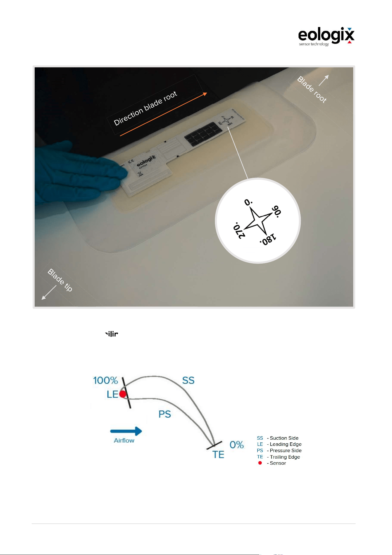
OperationandServiceManual_V1_4_EN_eologix
© eologix sensor technology gmbh 2023
eologix.com 72 | 125
Figure 32 Adjusting the sensor
Distance from the trailing edge of the rotor blade
The following figure explains the distance from the trailing edge of the rotor blade (Distance
trailing edge (%)).
Figure 33 Distance Trailing Edge in % - with an example of a sensor at 100%.
The distance from the trailing edge of the rotor blade is given in [%] (see mounting positions
(Distance trailing edge (%)):
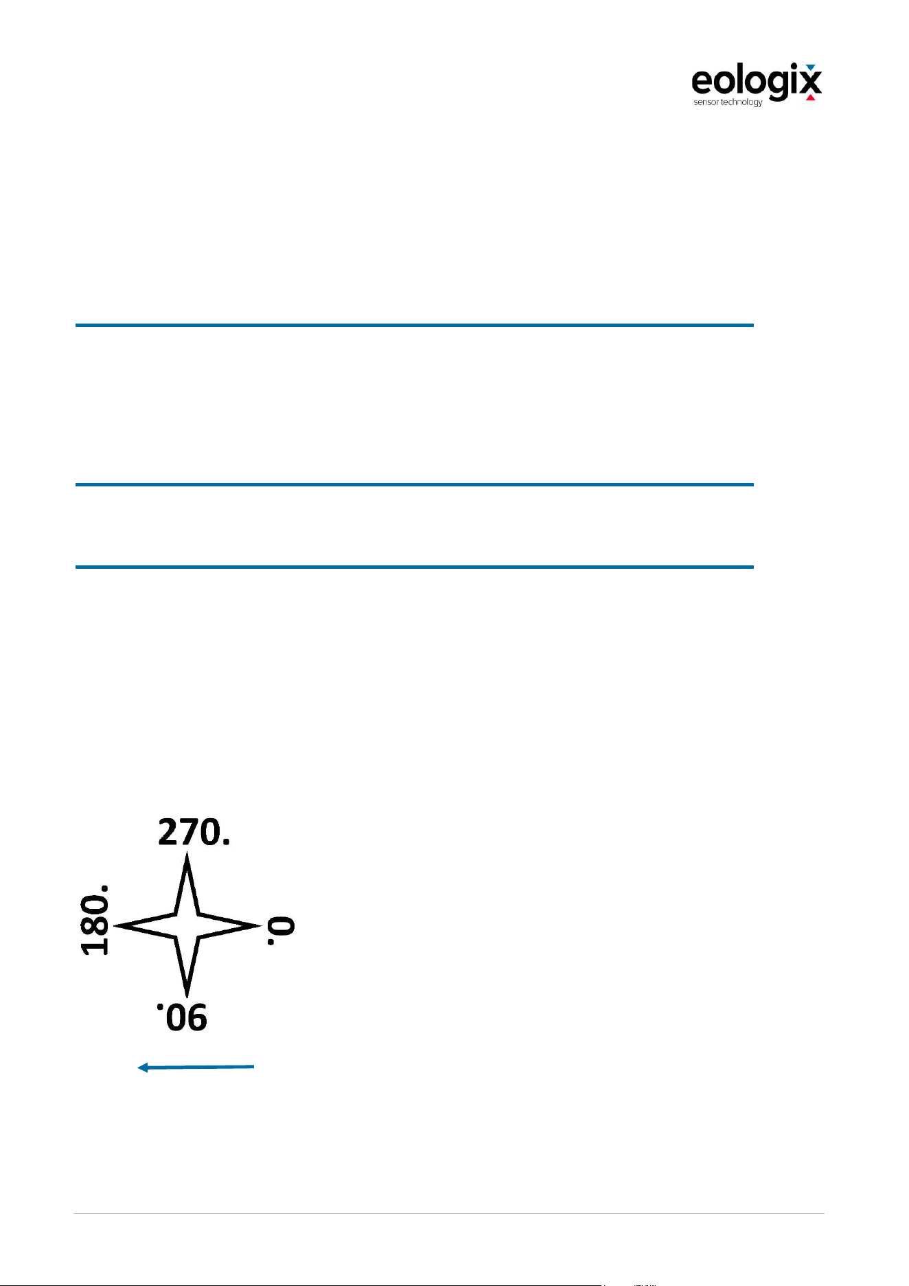
OperationandServiceManual_V1_4_EN_eologix
© eologix sensor technology gmbh 2023
eologix.com 73 | 125
How the sensor is adjusted depends on the application position in relation to the rotor blade's
trailing edge. The distance from the rotor blade's trailing edge is given in [%]:
100% = LE - Distance trailing edge (%)
Sensor is mounted directly on the leading edge of the rotor blade (only 0° or 180°
orientation is allowed)
>= 90% = LE - Distance trailing edge (%)
Sensor is mounted as close as possible to the leading edge of the rotor blade
(only 90° or 270° orientations are permitted). The erosion protection foil of the
sensor ("thin" area) must always be taped over the leading edge. See section:
"Important notes".
50% = MID - Distance trailing edge (%)
Chordwise in the middle between the leading and trailing edge of the rotor blade.
<= 10% = TE - Distance trailing edge (%)
The erosion protection tape must cover over the trailing edge of the rotor blade
(i.e. the entire sensor plus tape must be stickedf on one side of the blade)
The wind rose shown on the sensor is used to correctly align the sensor.
Wind rose (the number pointing in the direction of the rotor blade root is noted in the
documentation).
Direction to rotor blade root (in this example 180°)
Figure 34 Wind rose on the sensor
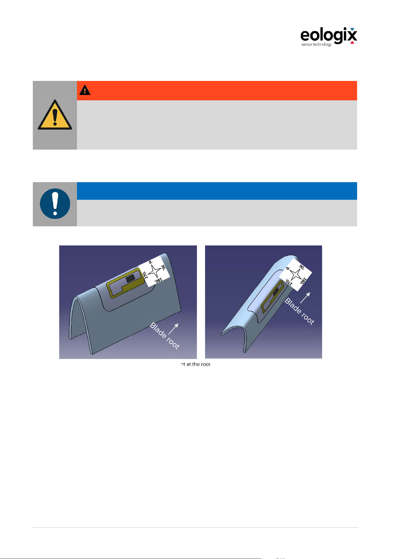
OperationandServiceManual_V1_4_EN_eologix
© eologix sensor technology gmbh 2023
eologix.com 74 | 125
W A R NIN G
There must be a distance of at least 1 m between the sensors and lightning receptors, otherwise
they might be damaged.
Avoid areas on the rotor blade where the distance between sensor and lightning arresters
within the blade is less than 3 cm.
N O T ICE
If the sensor is applied directly at the rotor blade's leading edge (>90%), the wide side of the
tape must be applied over the rotor blade's leading edge: wind rose 90° (as shown below)
Figure 35 Alignment at the root of the rotor blade
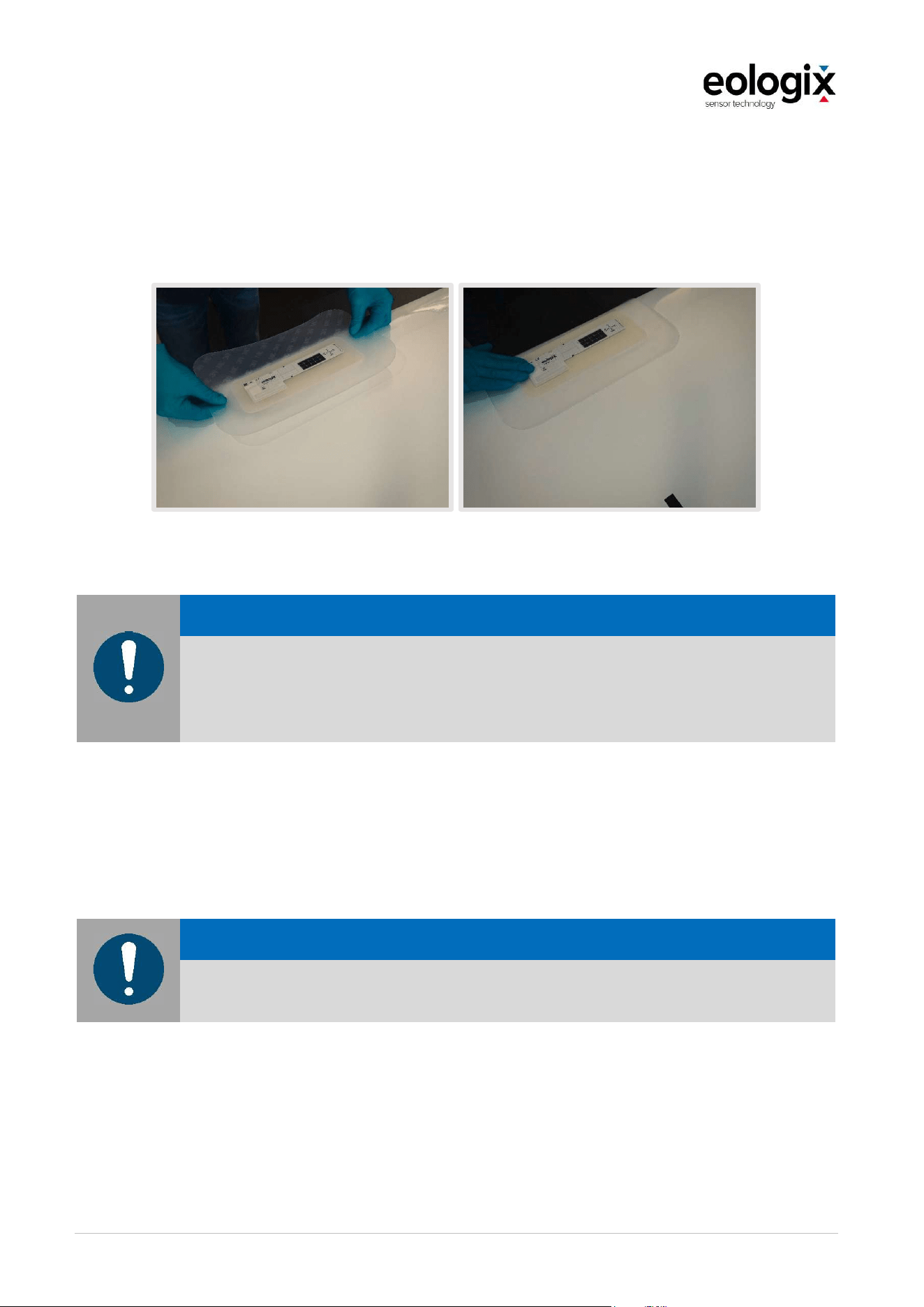
OperationandServiceManual_V1_4_EN_eologix
© eologix sensor technology gmbh 2023
eologix.com 75 | 125
5.6.7
Adhering
Step 5: Apply the sensor correctly.
In this step, the sensor with the now self-adhesive back is glued onto the rotor blade in the
correct position (according to the specified mounting positions and the following explanations).
Figure 36 Adhering the sensor
N O T ICE
The edges of the sensor tape may especially at the rotor blade's leading edge not be directly
exposed to wind flow - in that case, it may be necessary to apply an additional tape after
consultation with eologix sensor technology but it has to be ensured that no second tape layer
is applied onto the sensor area (marked with two black triangles)
Step 6: Applying the assembly spray.
Wet the surface of the rotor blade with installation spray (75% water & 25% isopropanol): the
surface on which the erosion protection tape will be placed should be completely wetted.
N O T ICE
There may not be any liquid underneath the sensor. It must, as outlined in step 5, already be
firmly adhered to the rotor blade before the application spray is applied.
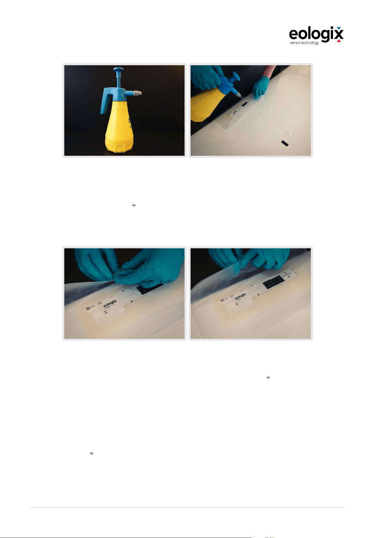
OperationandServiceManual_V1_4_EN_eologix
© eologix sensor technology gmbh 2023
eologix.com 76 | 125
Figure 37 Apply assembly spray
For more information, visit the assembly spray manufacturer's website www.3M.com/wind for
instructions on how to use 3M Application Solution Spray.
Step 7: Remove the protective tape from the surrounding Wind Protection Tape.
Figure 38 Remove protective tape from surrounding
In step 7, remove the transparent protective tape (patterned with "3M "). Now also spray the
sticky side of the Wind Protection Tape with mounting spray. Then apply the erosion protection
tape to the blade surface.
Step 8: Strike out application solution
Spread the Application Solution between the tape and the rotor blade surface with the spatula
- For this step 3M recommends the "Wet or Dry Rubber Squeegee Part.No 05517".
Only the erosion protection foil around the circuit board may be worked on with the spatula!
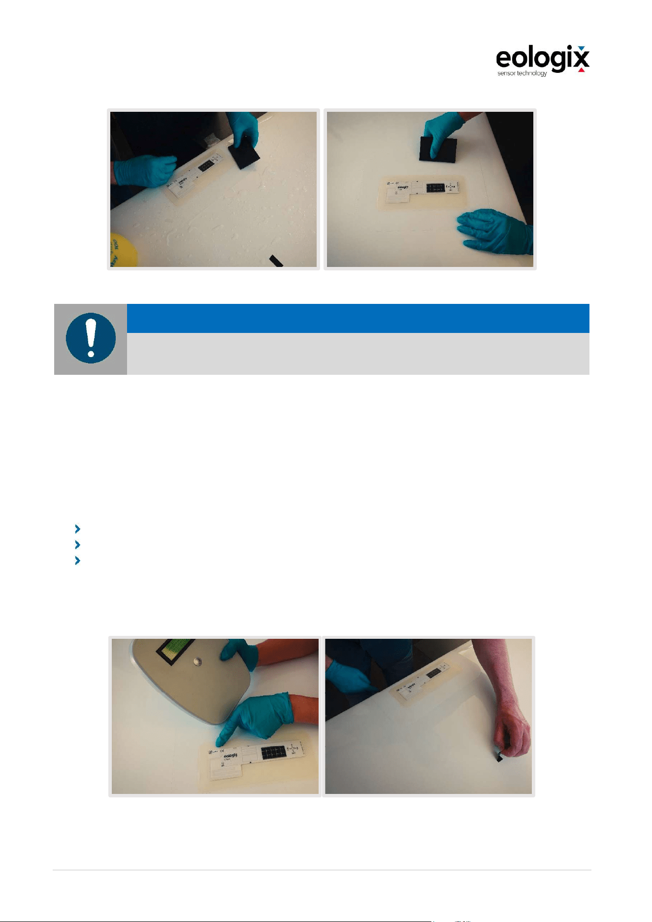
OperationandServiceManual_V1_4_EN_eologix
© eologix sensor technology gmbh 2023
eologix.com 77 | 125
Figure 39 Strike out application solution
N O T ICE
The raised part of the sensor (circuit board, white) must NOT be worked on with the spatula.
5.6.8
Inspection
Step 9: Checking the sensor and removing the marking
After mounting, check the sensor with the eologix handheld reader. Each sensor ID displayed
on the handheld reader confirms the function of this sensor. If a sensor is not displayed even
after one hour in daylight, proceed as follows:
Remove sensor (as seen in Chapter 8.3)
Attach a new sensor.
Send the defective sensor including the picture documentation of the attachment and
removal back to eologix in order to clarify the cause of the defect
After the sensor has been successfully tested, the piece of insulating tape used for must be
removed again.
Figure 40 Inspection of the sensor
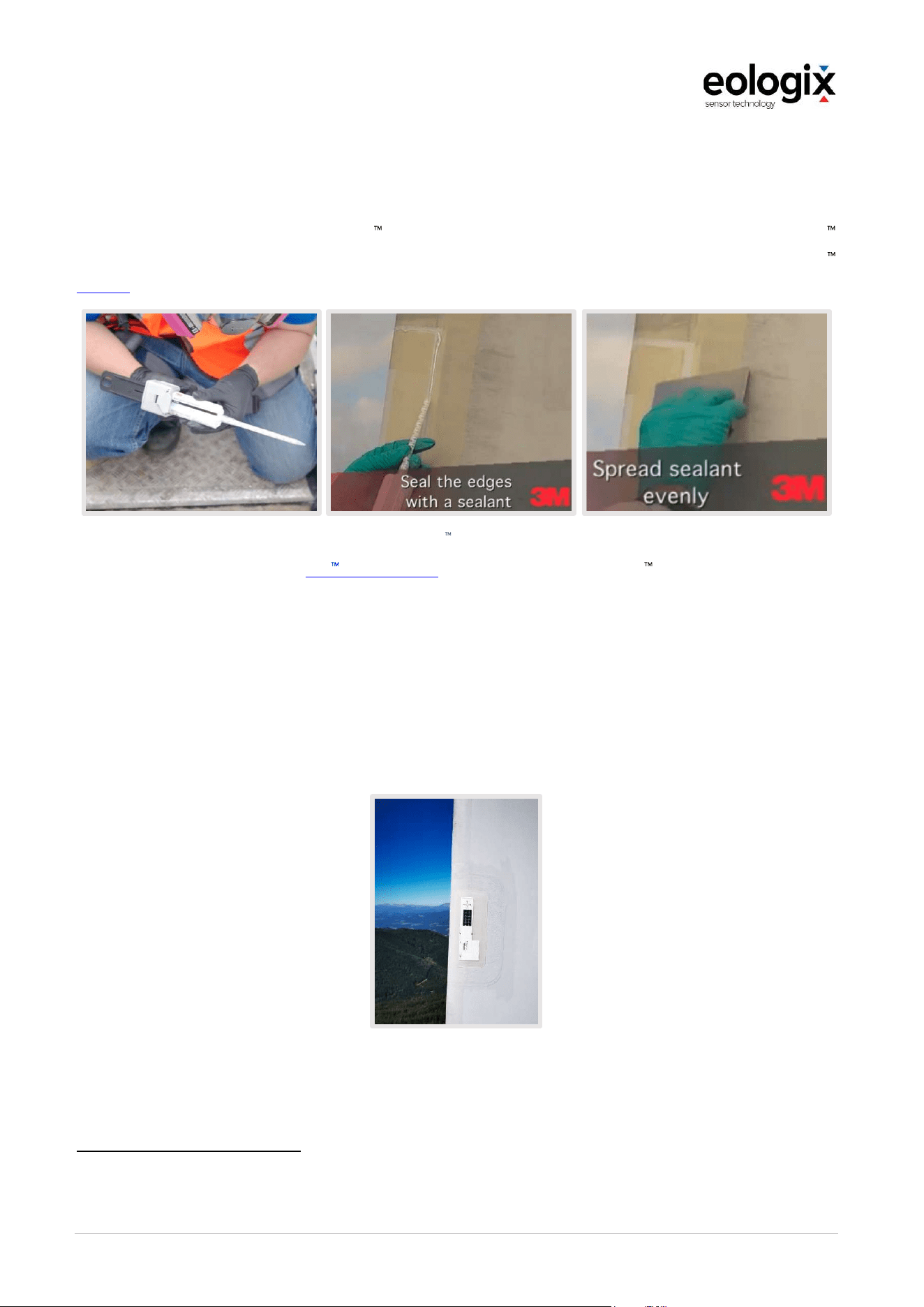
OperationandServiceManual_V1_4_EN_eologix
© eologix sensor technology gmbh 2023
eologix.com 78 | 125
5.6.9
Sealing
Step 10: Edge sealing
Make sure the surface is dry. Use 3M Wind Protection Tape Edge Sealer W2600 with the 3M
EPX Applicator to seal the edge between the tape and the rotor blade (as shown in the 3M
video
2
). Use a plastic spatula to spread the sealer evenly.
Source: How to install: 3M Wind Blade Protection Tape
Please refer to the relevant 3M data sheet
3
for the application of 3M Wind Protection Tape
Edge Sealer W2600. Furthermore, ensure dry weather conditions (no wet rotor blade surface,
no rain, condensing mist, etc.) before and during installation as well as for a few hours
afterwards (curing time which is temperature dependent). The Edge Sealer must NEVER be
exposed to moisture before and during curing.
Once the Edge Sealer has been applied, the sensor installation is complete. Now all steps of
the mounting process are completed. Now follows the documentation of all glued sensors.
The following figure shows an example of what a fully assembled sensor should look like:
Figure 41 Example of an applied sensor
2
https://www.youtube.com/watch?v=YzWu4frzz04
3
https://multimedia.3m.com/mws/media/630797O/3m-wind-protection-tape-edge-sealer-w2600.pdf

OperationandServiceManual_V1_4_EN_eologix
© eologix sensor technology gmbh 2023
eologix.com 79 | 125
5.6.10
Documentation
Step 11: Documentation
Two documentations must be prepared for each sensor: Image documentation and written
documentation.
Image documentation
The image documentation must be in high resolution (per sensor ONE close-up image incl.
readable sensor ID and ONE distance image incl. foil, seal and sensor ID must be readable).
The following is an example of sufficient image documentation:
Figure 42 Image documentation an example
Written documentation
The written documentation consists of two parts: on the one hand, the written documentation
of the position of the sensor IDs in the XLSX file, which is provided as a template by eologix,
and on the other hand, the function check by using the manual reader and its confirmation by
the rope access worker.
Written documentation: ID Position
The written documentation is done in the positioning table provided by eologix (see exemplary
in Figure 5). The ID numbers of the sensors are documented in the respective cell (position on
the sheet) of the Excel.
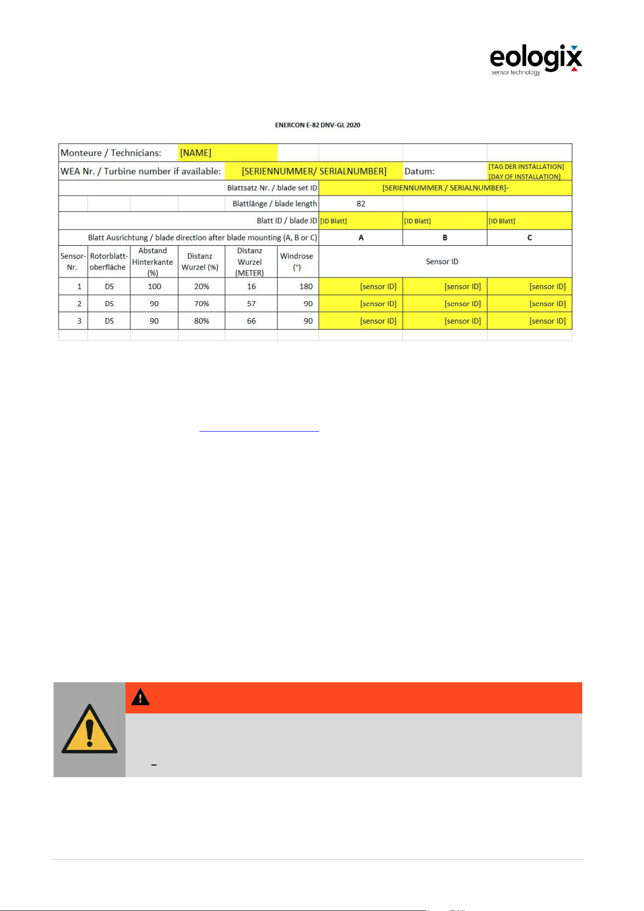
OperationandServiceManual_V1_4_EN_eologix
© eologix sensor technology gmbh 2023
eologix.com 80 | 125
Figure 43 Written Documentation Part 1: ID Sensor | Excel Sheet
The fully completed Excel file with all installed sensors and inserted sensor IDs and their
positions must be sent to [email protected] after installation.
Written documentation: Functional check
The functional check after mounting the sensor to the rotor blade using the manual reader
must be clearly documented (by means of photos of the handheld reader with the respective
sensor ID or a written confirmation of the function).
5.7
Commissioning and test operation
Commissioning and test operation of the product at the customer's may only be carried out by
qualified personnel of eologix sensor technology gmbh.
W A R NIN G
During commissioning, unexpected movements and processes can lead to different
dangers.
The product may only be commissioned by authorized and trained personnel

OperationandServiceManual_V1_4_EN_eologix
© eologix sensor technology gmbh 2023
eologix.com 81 | 125
6
OPERATION
The following chapters provide an overview of the operation of the product.
6.1
Use
The eologix ice detection system is certified by DNV. The certificate distinguishes between
three operating modes
Ice detection, meaning system stop because of icing
Automatic restart, meaning automatic system start if ice-free
Operation under ice load, meaning by means of measurement of ice thickness.
Only the first two operating modes will be covered in detail below. Customer-specific variations
of the sensor configuration (especially additional equipment or individual equipment for
specific purposes) are always possible.
6.1.1
Ice detection
Algorithm ice detection
The si ICE meaning: ice is detected and the system must be stopped) is output, if
Redundancy ice detection
In accordance with the certificate, the system requires at least two sensors at the tip and one
sensor at the
eologix:safe (9 sensors)
In this mode, a signal is generated according to the algorithm in the DNV component
certificate, which signals the system to stop due to safety-relevant icing. The positions of the
sensors are shown in chapter 5.5.1. The number of sensors does not depend on the blade
length.

OperationandServiceManual_V1_4_EN_eologix
© eologix sensor technology gmbh 2023
eologix.com 82 | 125
6.1.2
Automatic restart
Algorithm Automatic restart (Restart)
As soon as a sensor delivers "SIGNAL LEVEL 5" or a sensor delivers "SIGNAL LEVEL 4" or two
sensors on one blade deliver "SIGNAL LEVEL 3", the signal "AUTOSTART NOT OK" is output.
If this is not the case, the signal "AUTOSTART OK" is output and the system can restart
automatically.
Redundancy Automatic restart (Restart)
The function "Ice-free detection" can be continued as long as:
at least 66% of all sensors of the minimum requirement are active,
at least 2 blade tip sensors (sensors at positions >70% of the blade length) are active on
2 blades,
at least one sensor is active every 30 m on each leading edge.
If not all of the above conditions are met, the signal "AUTOSTART NOT OK" is always output.
Here, too, each sensor is redundant at least once (i.e. each sensor position is covered by at
least one other sensor).
eologix:restart (number of sensors depending on blade length)
For the detection of ice-free conditions and thus the automatic restart, a higher number of
sensors must be used and this also depends on the blade length. In the following, the required
number of sensors according to the certificate is listed for exemplary wind turbine
manufacturers and blade lengths:
Turbine type Blade length Number of sensors
X70 34 m 21
X82 39,5 m 21
X90 43,5 m 21
X115 56 m 21
X126 61,5 m 24
X136 66,5 m 24
X180 88 m 24
With every eologix:restart system, the necessary positions for ice detection are covered
several times. This means that every eologix:restart system is also suitable for the ice detection
function.

OperationandServiceManual_V1_4_EN_eologix
© eologix sensor technology gmbh 2023
eologix.com 83 | 125
6.1.3
Operation under ice load
Operation under ice load, i.e. due to the continuous ice thickness measurement, the system
can continue to be operated in non-safety-critical areas up to a certain degree of icing. Further
information on this is available on request.

OperationandServiceManual_V1_4_EN_eologix
© eologix sensor technology gmbh 2023
eologix.com 84 | 125
6.2
Handling
The product is set up via the interface in the course of commissioning. Afterwards, no further
operational steps are necessary, the eologix sensor system is fully automated.
6.3
Assessment of probability of failure
DNV certification requires a probability of failure assessment in accordance with ISO
13849:2008.
Redundancy of the sensors
Redundancy of the receiving units:
o
2 antennas and
o
2 separate receiving units in the base station as well as
various measures in the control unit, e.g.
o
Hardware watchdog,
o
test equipment according to FMEA and
o
plausibility check of the measurement data
the following property could be verified according to ISO 13849:2008:
Performance Level=PLr=d, this corresponds to a failure probability of 10
-7
to 10
-6
.
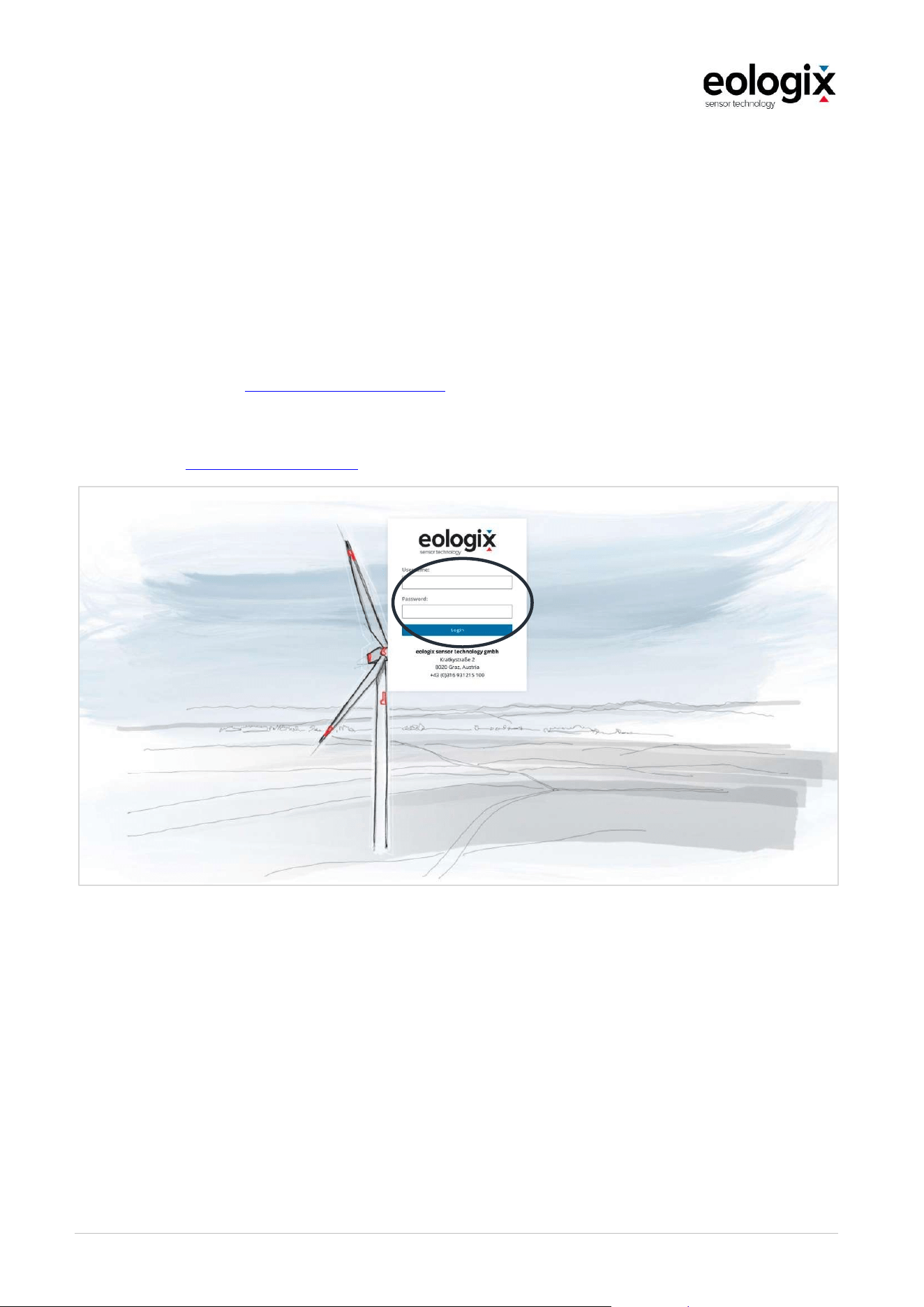
OperationandServiceManual_V1_4_EN_eologix
© eologix sensor technology gmbh 2023
eologix.com 85 | 125
6.4
Read-out
With an existing internet connection of the base station, it is also possible to store the
measurement data online (on own eologix servers in Graz, Austria) and to display historical
data via the eologix web interface by means of visualisation.
6.4.1
Login
On our online portal http://online.eologix.com you have the possibility to receive automated
measurement data of your wind turbine from our eologix server. To do this, use your current
user password combination in the login area. If you do not know any login data, please
contact us at [email protected].
Figure 44 Login

OperationandServiceManual_V1_4_EN_eologix
© eologix sensor technology gmbh 2023
eologix.com 86 | 125
6.4.2
Main page
After logging in, you are directly on our main page - in your own home area. This area offers
you the possibility to check and evaluate all current and historical data of your system.
Figure 45 Main page

OperationandServiceManual_V1_4_EN_eologix
© eologix sensor technology gmbh 2023
eologix.com 87 | 125
6.4.3
Selection base station
You can now select your desired eologix system in the field shown below.
Figure 46 Select your base station
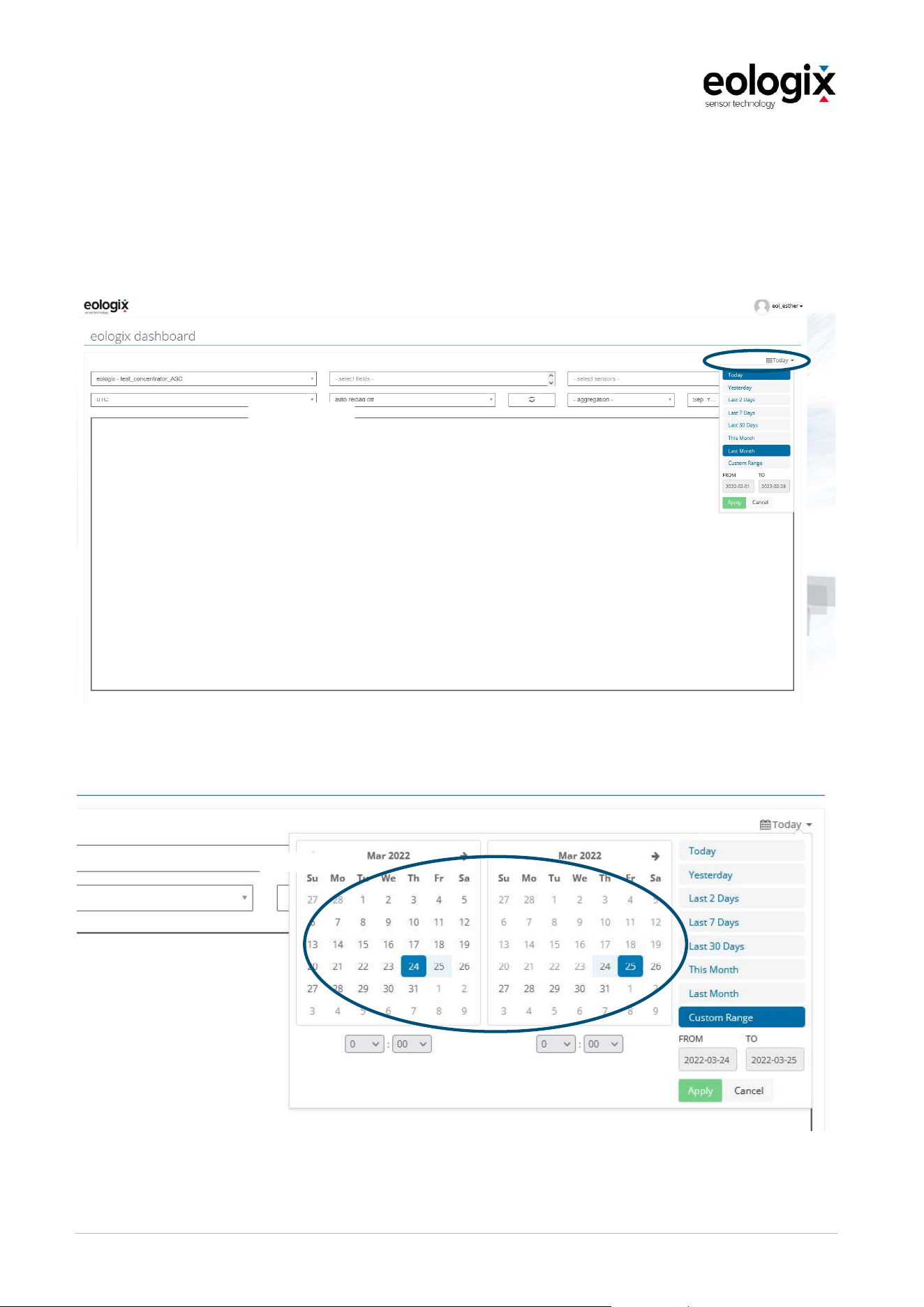
OperationandServiceManual_V1_4_EN_eologix
© eologix sensor technology gmbh 2023
eologix.com 88 | 125
6.4.4
Time
Define a time - you can choose between a time or a period. If you do not enter a time, data
from the current day will be displayed (Today). Alternatively, you can also zoom in the graph
with your mouse wheel or move the graph forward or backward in time by holding down the
left mouse button.
Figure 47 Time
Figure 48 Selecting a time period

OperationandServiceManual_V1_4_EN_eologix
© eologix sensor technology gmbh 2023
eologix.com 89 | 125
6.4.5
Sensor selection
Figure 49 Sensor selection
6.4.6
Measured variables
Measured
variable
Type of signal Description
Temperature
Individual signals of
individual sensors
Surface temperature of every individual sensor
Ice Signal
Individual signals of
individual sensors
Ice level (meaning ice thickness on surface) of each individual
sensor
(Level 1 5).
Ice Warning System signal Ice-stop signal of system
Ice Restart System signal Automatic restart signal
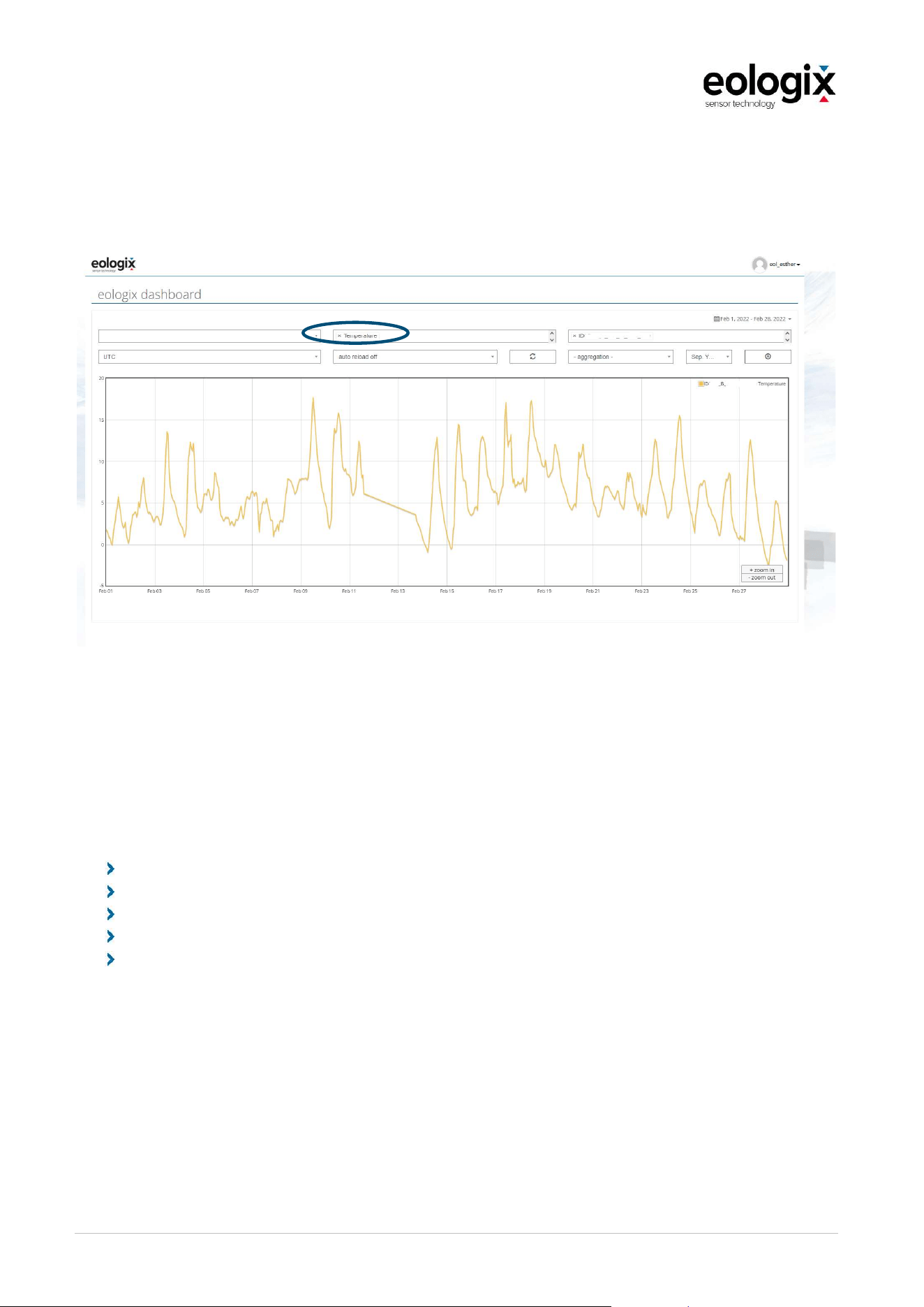
OperationandServiceManual_V1_4_EN_eologix
© eologix sensor technology gmbh 2023
eologix.com 90 | 125
6.4.7
Temperature
An exemplary temperature curve is shown below.
Figure 50 Temperature curve (example 1 sensor)
6.4.8
Ice Signal
This value shows you the current and historical ice levels for each sensor. The four discrete
ice levels (1, 2, 3, or 4) indicate the surface condition in relation to ice. For a detailed description
of the sensor's ice levels, see chapter 4.2.3:
1 = Free surface
2 = Very thin layer (<1 mm) or wetness
3 = Ice from 1-2 mm
4 = Ice from 10 mm
5 = Ice from 15 mm
In the web interface, this data can again be displayed retrospectively and in real time.
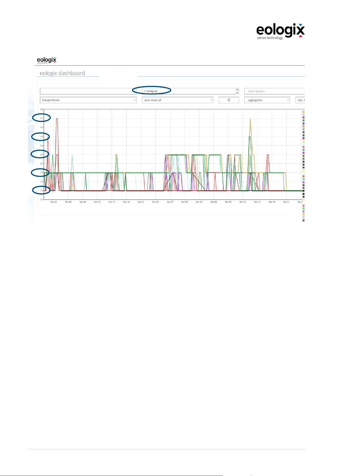
OperationandServiceManual_V1_4_EN_eologix
© eologix sensor technology gmbh 2023
eologix.com 91 | 125
Figure 51 Ice Signal
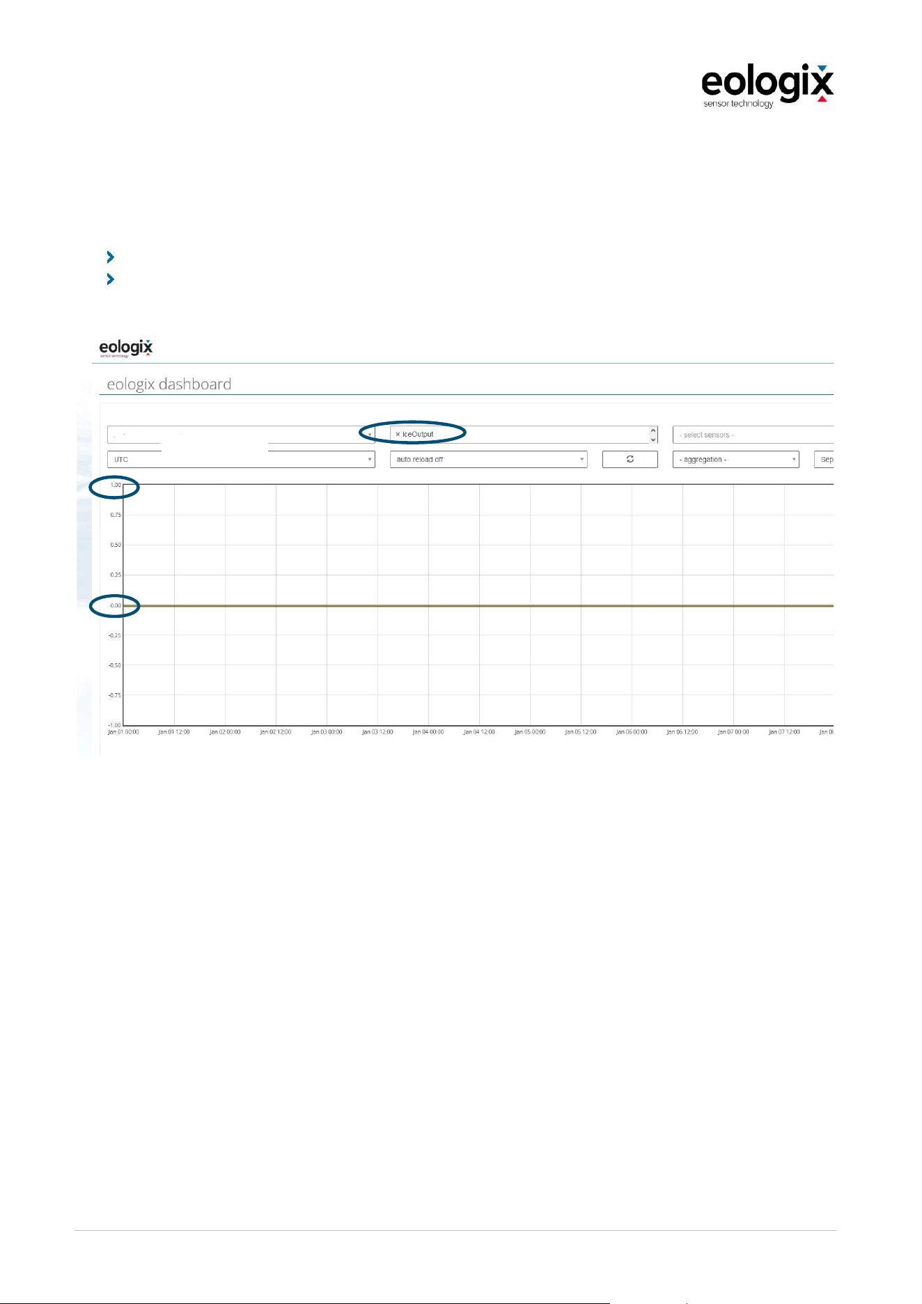
OperationandServiceManual_V1_4_EN_eologix
© eologix sensor technology gmbh 2023
eologix.com 92 | 125
6.4.9
Ice Warning
The Ice Warning (formerly Ice Output) displays your base station's control signal to stop the
system due to ice. Each sensor gives you the same sensor output signal.
1: Wind turbine is stopped due to icing
0: Wind turbine can be operated
Figure 52 Ice Warning
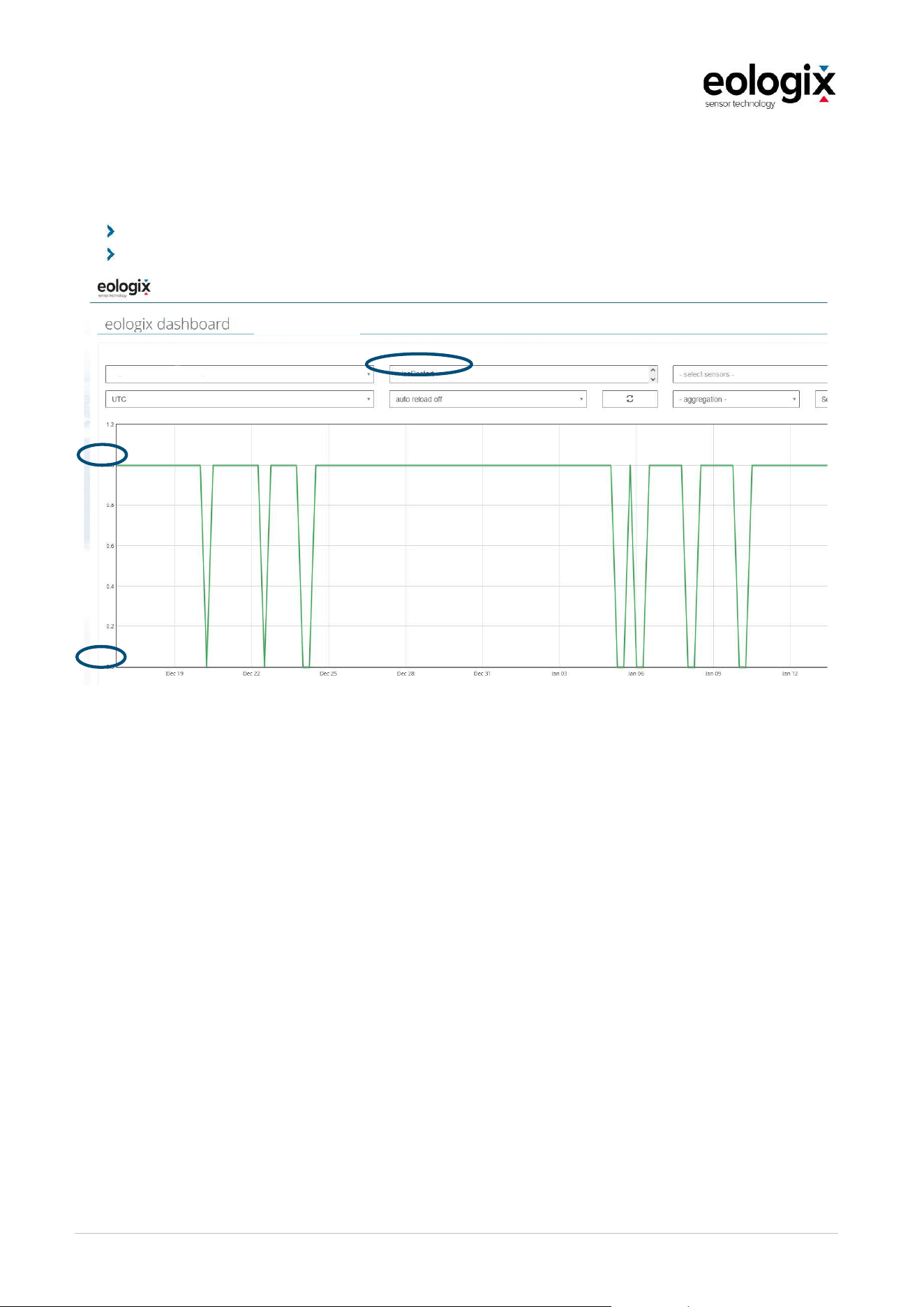
OperationandServiceManual_V1_4_EN_eologix
© eologix sensor technology gmbh 2023
eologix.com 93 | 125
6.4.10
Ice Restart
This control signal defines a possible automatic restart of the wind turbine after an ice stop.
1: automatic restart of the wind turbine is possible
0: Automatic restart of the wind turbine is NOT possible.
Figure 53 Ice Restart
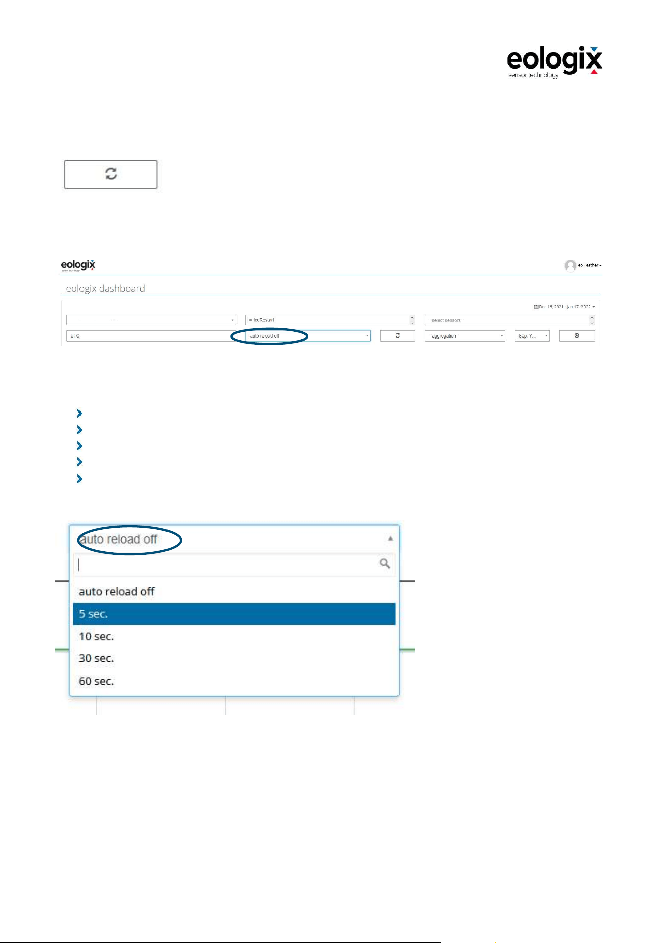
OperationandServiceManual_V1_4_EN_eologix
© eologix sensor technology gmbh 2023
eologix.com 94 | 125
6.4.11
Update settings
You have the possibility to update your data. Please use the following button:
The data can also be updated automatically.
Choose between the following updates:
5 seconds
10 seconds
30 seconds
60 seconds
auto reload off (no automatic update)
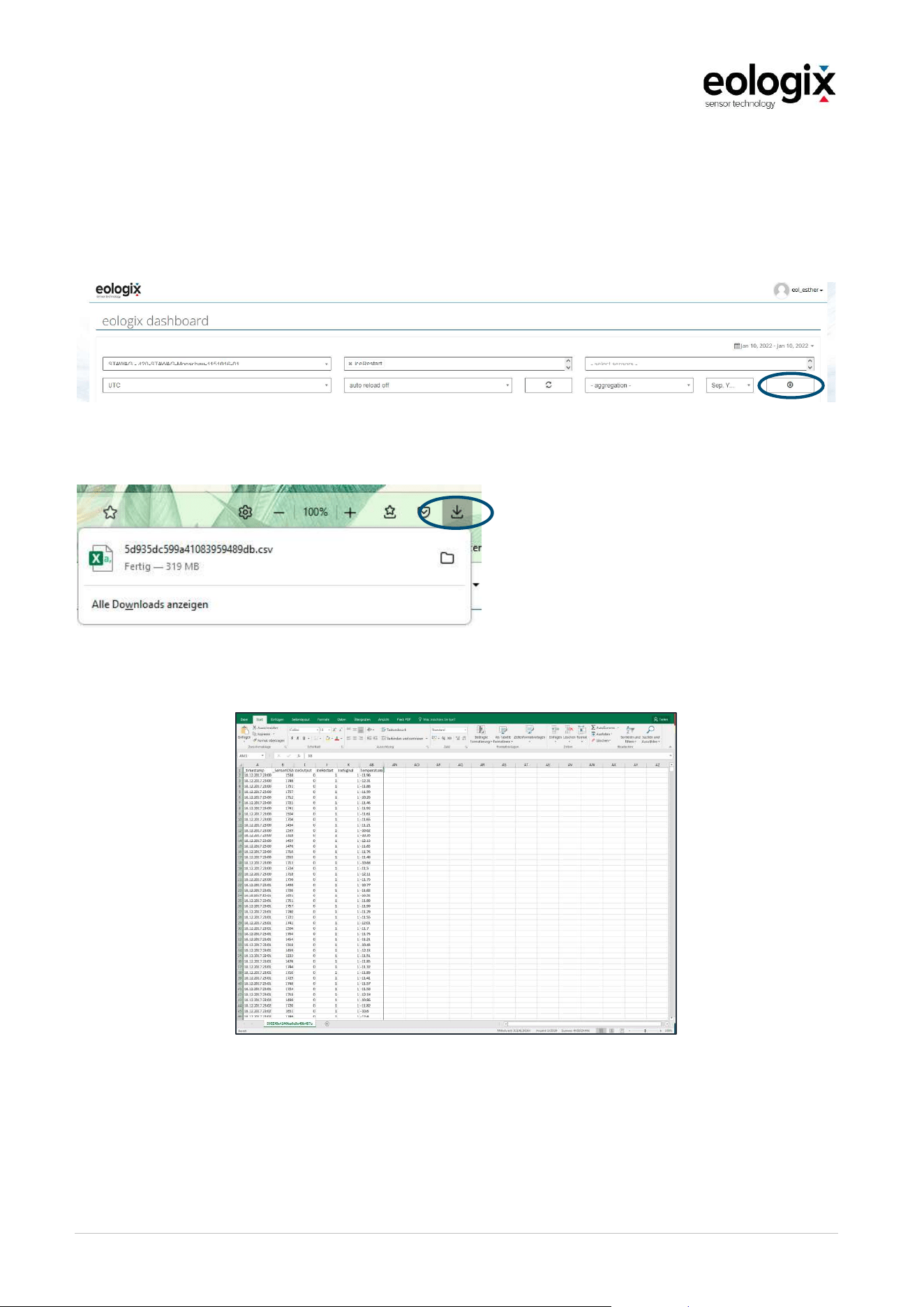
OperationandServiceManual_V1_4_EN_eologix
© eologix sensor technology gmbh 2023
eologix.com 95 | 125
6.4.12
Data download
You can also view and save your current and historical data externally. Use the download
button to create a .csv file of the selected period.
Download starts automatically.
Figure 54 Data download
Data is opened in MS Excel, for example.
Figure 55 Data export as .csv

OperationandServiceManual_V1_4_EN_eologix
© eologix sensor technology gmbh 2023
eologix.com 96 | 125
6.4.13
Automatic data download
An HTML link is entered directly in the browser to download data on a specific eologix system
in a specific time period.
Depending on whether the time is to be displayed in days or in seconds, there are 2 different
links
1.
Time defined in days
http://USER:PASSWORD@online.eologix.com/api/download?uid=CONCENTRATOR_
UID&from=DATE_FROM&to=DATE_TO
2.
Time defined in seconds
http://USER:PASSWORD@online.eologix.com/api/download?uid=CONCENTRATOR_
UID&from=TIMESTAMP_EPOCH_FROM&to=TIMESTAMP_EPOCH_TO
The link must be adapted depending on the desired evaluation result and contains:
-
USER: User data from the dashboard (e.g.: eol_Kunde1)
-
PASSWORD: Password for the user of the dashboard
-
CONCENTRATOR_UID: provided by eologix
Define time in days:
-
DATE_FROM: Start date of the download (e.g.: 2021-06-21)
-
DATE_TO: Date end of download (e.g.: 2021-06-22)
Define time in seconds:
-
TIMESTAMP_EPOCH_FROM: Date Start of download in ms in Unix time (e.g.
1624230000000).
-
TIMESTAMP_EPOCH_TO: Date End of download in ms in Unix time (e.g.
1624316400000).
Explanation of Unix time: https://de.wikipedia.org/wiki/Unixzeit
Convert: https://tools.confirado.de/timestampconverter/index.php

OperationandServiceManual_V1_4_EN_eologix
© eologix sensor technology gmbh 2023
eologix.com 97 | 125
6.5
Hardware and interface specification
For further tables with Modbus registers see appendix or contact eologix sensor technology if
required.
6.5.1
User interface
Inside the base station, there are LEDs on the IPC that indicate the following functionalities:
Colour Description Status Description
Green POWER On Supply voltage available
Green POWER Off No supply voltage available
Green STATUS 2x
blinking
Microchip (µC) Heartbeat
Red STATUS On The controller has received a message from a sensor
assigned to the system on this very turbine
Blue STATUS 2 1x blinking System has connection to network
Blue STATUS 2 2x
blinking
System has connection to eologix database
Orange ACTIVITY blinking The controller has a message from any sensor
6.6
Faults/error recovery
Malfunctions may occur in the product, which are indicated by the status message. In the event
of malfunctions or errors, contact eologix sensor technology gmbh immediately. The following
table lists common malfunction messages, their causes and steps to correct the problem.
Fault Cause Measure
LED Power not green No supply voltage Check supply voltage
No LED on eologix IPC No supply voltage Check supply voltage

OperationandServiceManual_V1_4_EN_eologix
© eologix sensor technology gmbh 2023
eologix.com 98 | 125
7
MAINTENANCE
The tasks necessary for maintenance are outlined in the following chapters: inspection,
cleaning, servicing, spare part management as well as corrective maintenance.
N O T ICE
General notices.
The following information must be observed, additionally, the notices included in the
respective documentation by the original manufacturer may not be ignored.
The operator is responsible for ensuring that this information is observed.
All measures necessary for inspection, corrective maintenance and servicing must be
carried out in accordance with the national regulations of the country of use.
All services, tests and retests defined by standards, laws, regulations and other
provisions must be planned and carried out by the operator or they must commission
somebody to carry them out.
7.1
Cleaning
When carrying out cleaning activities on the product, the following must be observed:
Before cleaning, the product must be disconnected from the power supply and
depressurized.
Cleaning activities may only be carried out by instructed personnel who have been
informed about the dangers that could arise from this product.
N O T ICE
General notices regarding cleaning activities.
only with soft, non-scratching cleaning cloths
when cold, with cleaning fluid
never use compressed air for cleaning
wear adequate personal protective equipment

OperationandServiceManual_V1_4_EN_eologix
© eologix sensor technology gmbh 2023
eologix.com 99 | 125
7.2
Service
servicing"), especially by means of settings (i.e. adjusting) or by means of replacing filters, seals
and lubricants, cleaning etc.
A regular inspection of the product every two years contributes to safety and saves time and
money.
7.2.1
Service manual base station
Recurring service measures of the base station are restricted to visual inspection regarding
visible damages (i.e. due to bumps, vibrations, heat exposure).
In the event of detected damages, the customer is asked to immediately inform eologix and to
consult with eologix regarding the necessary procedure.
The base station CET214 must be replaced entirely. In individual cases it may be advisable to,
if instructed to do so, have individual components replaced by trained personnel. This refers
to the following components on the top-hat rail in the device (also see list of spare parts 7.2.3):
eologix receiver
eologix IPC
Surge protector ethernet
Surge protector element in the holder
7.2.2
Service manual sensor
The service measures include the regular visual inspection alongside the customary rotor
blade inspections (approx. every 2 years). In the event of detected damages (especially to the
wind blade protection tape of the sensor) the customer is asked to immediately inform eologix
sensor technology and to consult with eologix regarding the necessary procedure.
Minor damages to the wind blade protection tape can possibly be remedied by applying
another layer of tape (especially when the tape is damaged in areas outside the sensor).
Consult with eologix sensor technology regarding this procedure. Make sure not to apply a
second layer of tape onto the sensor area (marked with two black triangles).
OperationandServiceManual_V1_4_EN_eologix
© eologix sensor technology gmbh 2023
eologix.com 100 | 125
7.2.3
List of spare parts
For information regarding spare parts, please refer to the following list of spare parts. In the
event of uncertainties or questions or to order spare parts, please contact eologix sensor
technology.
Component Type Connections
eologix receiver eoREC214
1x cable RJ45
1x cable SMA
eologix IPC eoARM214
3x cable RJ45,
1x screw clamp 24VDC 2-polig
1x plug strip modem connection
Phoenix Contact surge protector
Ethernet DT-LAN-CAT.6+
No. 2881007
2x connections RJ45
Phoenix Contact surge protector
VAL-SEC-T2-1S-350-FM
No. 2905333
1x element in holder
W A R NIN G
Not using original spare parts and modifying the system can cause different dangers.
Only use original spare parts in accordance with the list of spare and wear parts.
Functional guarantee is only possible when original spare parts are used.
OperationandServiceManual_V1_4_EN_eologix
© eologix sensor technology gmbh 2023
eologix.com 101 | 125
7.3
Corrective maintenance
Corrective maintenance includes activities that exceed service as well as activities for fault-
free operation.
Corrective maintenance concludes, after inspection and service, the maintenance cycle and
ensures a long operational lifetime of the product and systems.
W A R NIN G
Miscellaneous hazardous events
During corrective maintenance activities on the product, additional locations of dangers
might be accessible.
Corrective maintenance activities may only be carried out by authorized,
trained
personnel. These personnel must also have read and understood this documentation.
N O T ICE
Improperly carried out corrective maintenance can lead to damage to the product.
Corrective maintenance activities resp. replacement of wear
parts must be carried out
by qualified personnel.
The maintenance personnel must, if applicable, observe the instructions of this
documentation and the instructions included in the displayed work instructions.
OperationandServiceManual_V1_4_EN_eologix
© eologix sensor technology gmbh 2023
eologix.com 102 | 125
8
DECOMMISSIONING
8.1
Switching off
To switch off the product, the following activities must be carried out:
1. Disconnect the base station from the power supply.
2. Protect the product against unauthorized recommissioning
3. If necessary, clean the product observing the instructions included in the respective
chapter
8.2
Final closing down
The following activities must be carried out before deinstalling the product for final closing
down in addition to the activities included in Switching off:
2. Disconnect the product from the power supply.
3. Remove equipment.
4. Deinstallation.
8.3
Deinstallation
W A R NIN G
During deinstallation activities, improperly carried out activities can lead to additional
dangers.
If the product is not deinstalled properly, dangers to persons might arise or the product
might be damaged.
Deinstallation activities on the product may on
ly be carried out by authorized and
trained personnel.
When deinstalling the product, the following must be observed:
Transport activities may only be carried out observing the transportation regulations
included in chapter 5.1 Transport.
If the product is put in storage after deinstallation, the requirements regarding the
storage locations included in chapter 5.2 Storage must be fulfilled.
If the product is disposed of, it must be disposed of observing the principle included in
chapter Disposal.
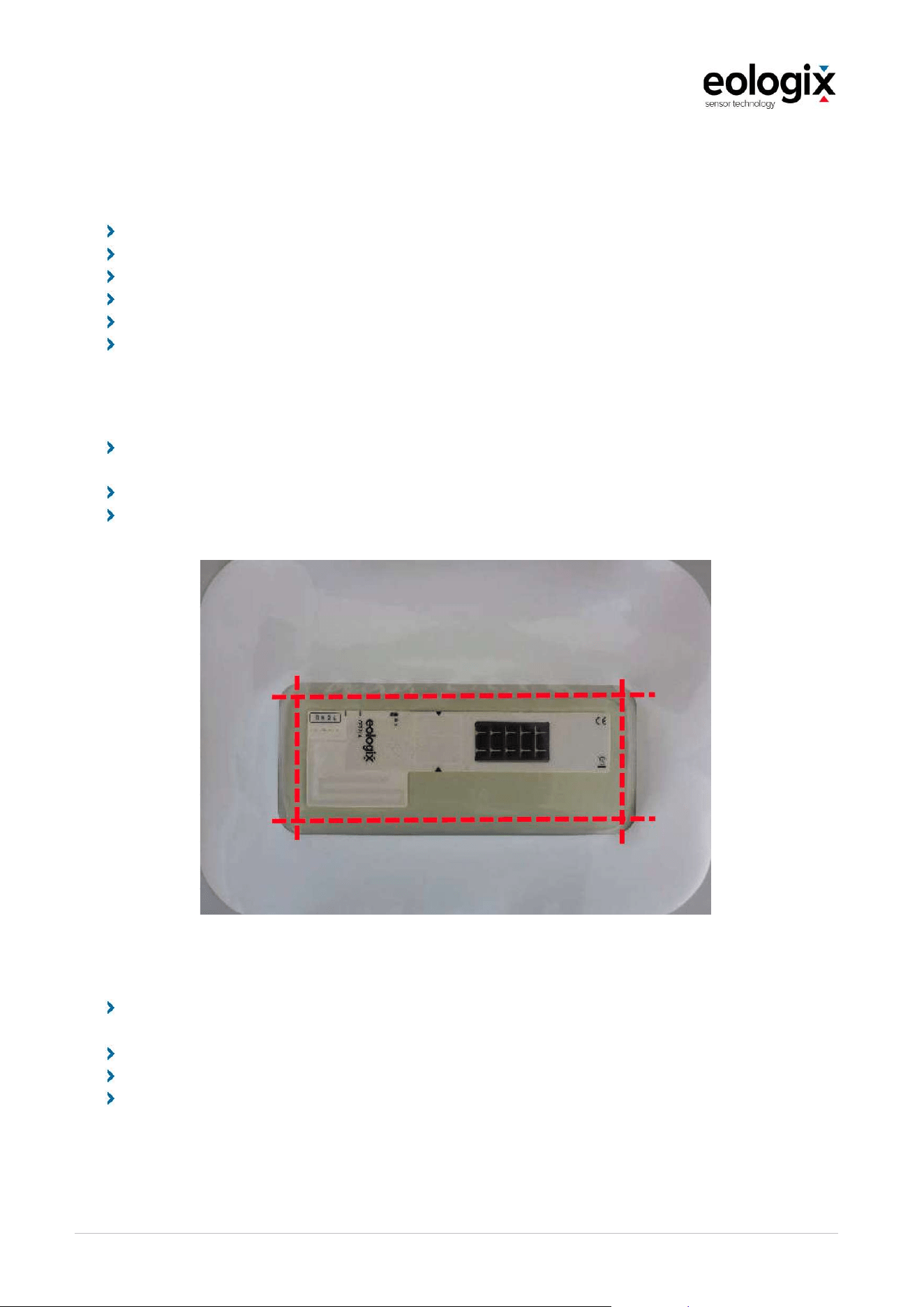
OperationandServiceManual_V1_4_EN_eologix
© eologix sensor technology gmbh 2023
eologix.com 103 | 125
8.3.1
Instructions for sensor removal
Tools
Knife (pointed blade, must be able to puncture the wind tape)
Storage container (i.e. bag) for removed sensors, trash bag
Spreader, sanding paper 320
poss. heating pad, hot-air blower depending on ambient conditions
poss. 3M TARR W9900, gloves, spreader, synthetic foil
Cotton or microfiber cloth
Step 1: Removing the sensor
Cut through wind tape and silicone encapsulation using a knife in the area of the bevel
of the silicone encapsulation and cut out the sensor (for cutting lines, see image below).
Do not damage the electronics located in the indicated area.
Retain the sensor to later return it (inspection, recycling/disposal, poss. further use) and
do not fold it!
Figure 56 Deinstallation
Step 2: Removing the remaining wind tape
Remove the remaining tape (dispose), if necessary, using a heat source and/or a
spreader
Remove adhesive residues: sanding paper or suitable electric tool
Clean with application spray (3M Application Solution Spray)
if necessary: 3M TARR W9900 (+ thin synthetic foil for cover, spreader, gloves, cloth)
When done: always return de-applied sensors to eologix sensor technology for inspection.

OperationandServiceManual_V1_4_EN_eologix
© eologix sensor technology gmbh 2023
eologix.com 104 | 125
Ambient conditions
Higher blade temperatures make the adhesive on the back side of the wind tape more elastic.
It is then easier to remove the adhesive foil, but adhesive residues on the blade are typically
harder to remove.
Notices regarding 3M TARR
For further information go to the website of the manufacturer www.3M.com/wind for
instructions regarding the use of 3M TARR W9900.

OperationandServiceManual_V1_4_EN_eologix
© eologix sensor technology gmbh 2023
eologix.com 105 | 125
8.4
Disposal
Base station
IN FO R M A TIO N
Disposal - Principle
Dispose of the parts of the product in the course of final decommissioning in a way
that does not harm nature and sorted by material (waste electronic equipment at
respective collection points, metal to respective scrap metal, plastics to plastic waste,
waste oil and liquids in accordance with legal regulations etc.!)
Principle
Before disposing of materials and parts of the product, check whether they are reusable.
Recycle as much of it as possible.
Careless or wrong disposal can result in unforeseeable damages.
Dispose of materials and parts of the product in a way that does not harm man, nature and
environment.
Thereby, observe the information provided by the manufacturers and the applicable laws and
regulations.
Base station
Dispose of the materials and parts of the base station after separating them by material.
Electric waste at waste treatment points for electric waste equipment and collection
points
Plastics
Sensor
Always return the sensor element that is to be disposed of to eologix sensor technology:
For inspection
for recycling and proper disposal of batteries and electronic components

OperationandServiceManual_V1_4_EN_eologix
© eologix sensor technology gmbh 2023
eologix.com 106 | 125
9
ATTACHMENT
9.1
Declaration of EC-conformity base station
OperationandServiceManual_V1_4_EN_eologix
© eologix sensor technology gmbh 2023
eologix.com 107 | 125
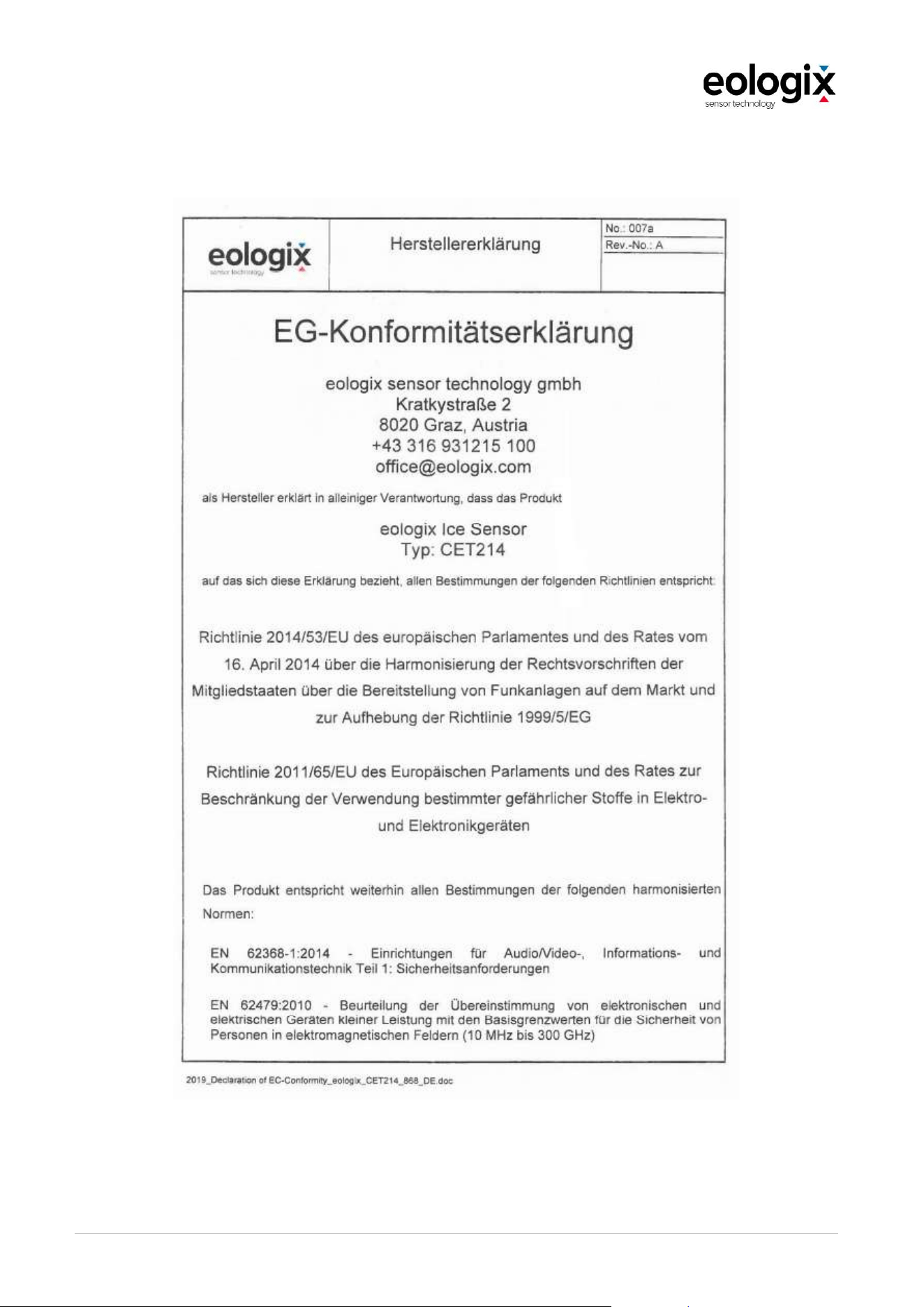
OperationandServiceManual_V1_4_EN_eologix
© eologix sensor technology gmbh 2023
eologix.com 108 | 125
9.3
Declaration of EC-conformity sensor unit
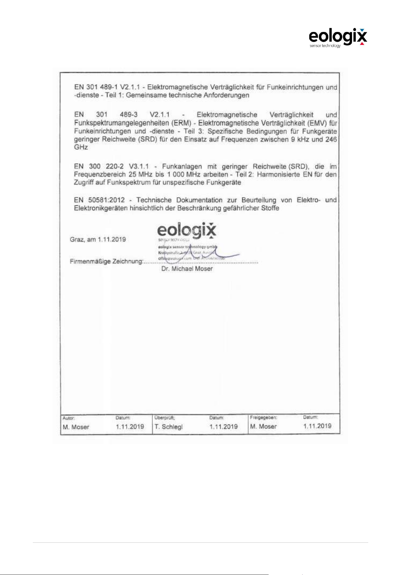
OperationandServiceManual_V1_4_EN_eologix
© eologix sensor technology gmbh 2023
eologix.com 109 | 125

OperationandServiceManual_V1_4_EN_eologix
© eologix sensor technology gmbh 2023
eologix.com 110 | 125
9.5
Modbus Specifications
9.5.1
Modbus Hardware/Interface Specifications
The Modbus daemon is available on both RJ-45 interfaces on BET214n.
customer requirements (DHCP or fixed IP)
customer requirements (DHCP or fixed IP)
TCP port 502
Modbus server ID 17
For the Modbus TCP/IP interface, the eologix base station works as a server in the Modbus
Client/Server architecture. Thus, any client has to pull a request for the sensor data or push
data to the server.
The eologix Modbus daemon implements the following data sets:
Data Set Register Type Description Start Address No. of registers
System Temps Input System Temperatures 64 7
Receiver RSSIs Input Receiver RSSI Values 80 2
Sensor Status Input Sensor Availability 96 2
Black Channel Input Security related data 128 4
Static Info 32bit Input
System configuration
(32bit)
240 6
Static Info Input
System configuration
and versioning
information
256 8
Sensor Info Input
Dynamic measurement
data from sensors
264 8·64
System Errors Input Error Values 1024 6
Attention: Values larger than a single register must be read with a single access spanning all relevant
registers.

OperationandServiceManual_V1_4_EN_eologix
© eologix sensor technology gmbh 2023
eologix.com 111 | 125
9.5.2
Server and Document Versions
The functionality of different Modbus server versions is shown below.
server /
document
version
input registers
system
temps
receiver
RRSIs
sensor
status
black
channel
static
info 32
static
info
sensor
info
system
errors
17.1
17.2
1
17.3
17.4 bugfix release
17.5 bugfix release
17.6 bugfix release
17.7.x bugfix release
17.8
17.9
17.10 bugfix release
17.11 bugfix release
17.12 bugfix release
17.13 bugfix release
17.14 bugfix release
18.1
18.2 bugfix release
20.1 bugfix release
20.1.1 specification extension
1
SensorID 16bit only.
9.5.3
Document formatting notes
Registers listed in light blue and marked [unused] are not implemented. Registers marked as
[RES]
are implemented and can be accessed.
Bitfields inside registers listed in light blue marked [unused] or [undefined] are implemented
and can be accessed.
Values in registers and bitfields typed in bold face are the default values in the unconfigured
state.

OperationandServiceManual_V1_4_EN_eologix
© eologix sensor technology gmbh 2023
eologix.com 112 | 125
9.5.4
Modbus Register Overview
Input Registers
Offset
Upper Byte
Lower Byte
0 .. 63 [unused]
64 TEMP_CPU_CORE
65 TEMP_UC
66 .. 70 [RES for temperatures]
71 .. 79 [unused]
80 RSSI_RX1_MAX
81 RSSI_RX2_MAX
82 .. 95 [unused]
96 ICING_STATUS
97 RESTART_STATUS
98 .. 127 [unused]
128 ID_BC NUM_PKT_BC
129 ICING [unused]
130 [unused] PROT_VERS
131 CRC_BC
132 .. 239 [unused]
240 ID_ARM_32 [upper]
241 ID_ARM_32 [lower]
242 ID_RX1_32 [upper]
243 ID_RX1_32 [lower]
244 ID_RX2_32 [upper]
245 ID_RX2_32 [lower]
246 .. 255 [unused]
256 SERVER_VERSION
257 TIMESTAMP_ARM [upper]
258 TIMESTAMP_ARM [lower]
259 ID_ARM
260 ID_RX1
261 ID_RX2
262 NB_REGS_PER_SENSOR
263 NB_SENSORS
264 Sensor 1: Timestamp [upper]
265 Sensor 1: Timestamp [lower]
266 Sensor 1: Sensor ID [upper]
267 Sensor 1: Sensor ID [lower]
268 Sensor 1: Temperature [upper]
269 Sensor 1: Temperature [lower]
270 Sensor 1: Ice Signal
271 Sensor 1: Error Signal
272 .. 279 Sensor 2 (signals as above)
280 .. 767 Sensors 3-63 (signals as above)
768 .. 775 Sensor 64 (signals as above)
776..1023 [unused]
1024 IPC_ERROR [upper]
1025 IPC_ERROR [lower]
1026 RX1_ERROR [upper]
1027 RX1_ERROR [lower]
1028 RX2_ERROR [upper]
1029 RX2_ERROR [lower]
1030 [unused]

OperationandServiceManual_V1_4_EN_eologix
© eologix sensor technology gmbh 2023
eologix.com 113 | 125
9.5.5
Data Volatility
Input Registers
Range
Data set
Volatility
64..70 System Temps single shot
80 .. 81 Receiver RSSIs single shot
96 .. 97 Sensor Status single shot
128 .. 131 Black Channel single shot
240 .. 245 Static Info 32b static
256 server version static
257 .. 258 timestamp single shot
259 .. 263 IDs static
264 .. 775 Sensor Info single shot
1024 .. 1029 System Errors single shot
Remark: a single shot volatility denotes discrete measurement points, with no relation to
past values, or calculated values.
Remark: static registers contain constant values, only changing on hardware exchanges or
software updates.

OperationandServiceManual_V1_4_EN_eologix
© eologix sensor technology gmbh 2023
eologix.com 114 | 125
9.5.6
Modbus Register Specifications: System Temperatures
They are of type InputRegister and therefore read-only.
Reg. Name Offset Datatype Content Byte order
2
TEMP_CPU_CORE 64 sint16
IPC CPU core
temperature
LSB 0.01°C
B2-B1
TEMP_UC 65 sint16
support uC
temperature
LSB 0.01°C
B2-B1
[RES] 66 -- [15..0] undefined n/a
[RES] 67 -- [15..0] undefined n/a
[RES] 68 -- [15..0] undefined n/a
[RES] 69 -- [15..0] undefined n/a
[RES] 70 -- [15..0] undefined n/a
If any sensor information cannot be accessed, the respective register will show an error value
as outlined below. These values are chosen to be out-of-band of valid values.
temperature -273.15 °C
2
Big endian. B1 least significant byte (bit0 to bit7), B4 most significant byte (bit24 to bit31).
Upper register of 32bit words listed first. Upper 8 bits of register listed first.
9.5.7
Modbus Register Specifications: Receiver RSSI values
They are of type InputRegister and therefore read-only.
Reg. Name Offset Datatype Content Byte order
3
RSSI_RX1_MAX 80 sint16
current max. RSSI
for receiver 1 over
all available
sensors
LSB dBm
B2-B1
RSSI_RX2_MAX 81 sint16
current max. RSSI
for receiver 1 over
all available
sensors
LSB dBm
B2-B1

OperationandServiceManual_V1_4_EN_eologix
© eologix sensor technology gmbh 2023
eologix.com 115 | 125
If any sensor information cannot be accessed, the respective register will show an error value
as outlined below. These values are chosen to be out-of-band of valid values.
RSSI -999 dBm
3
Big endian. B1 least significant byte (bit0 to bit7), B4 most significant byte (bit24 to bit31).
Upper register of 32bit words listed first. Upper 8 bits of register listed first.

OperationandServiceManual_V1_4_EN_eologix
© eologix sensor technology gmbh 2023
eologix.com 116 | 125
9.5.8
Modbus Register Specifications: Sensor Status
They are of type InputRegister and therefore read-only.
Reg. Name Offset Datatype Content Byte order
4
ICING_STATUS 96 sint16
sensor availability for icing
-1 = insufficient configuration
0 = insufficient sensors available
1 = one sensor until fail
2 = at least 2 sensors until fail
B2-B1
RESTART_STATUS 97 sint16
sensor availability for restart
-1 = insufficient configuration
0 = insufficient sensors available
1 = one sensor until fail
2 = at least 2 sensors until fail
B2-B1
available anymore if 1 further relevant sensor fails.
anymore.
4
Big endian. B1 least significant byte (bit0 to bit7), B4 most significant byte (bit24 to bit31).
Upper register of 32bit words listed first. Upper 8 bits of register listed first.

OperationandServiceManual_V1_4_EN_eologix
© eologix sensor technology gmbh 2023
eologix.com 117 | 125
9.5.9
Modbus Register Specifications: Black Channel
They are of type InputRegister and therefore read-only.
Reg. Name Offset Datatype Content
Byte
order
4
ID_BC 128.hi uint8 n/a
NUM_PKT_BC 128.lo uint8
packet number increased every
10s
int(Linux epoch/10)
n/a
ICING 129.hi uint8
[7..6] undefined
[5] 1 = ice warning
(depending on protocol
version, see below)
[4..3] reserved for
cond.monitoring
[2] 1 = ice-free detected
(where available)
[1] 1 = system OK
[0] 1 = icing detected
n/a
[RES] 129.lo -- [7..0] undefined --
[RES] 130.hi -- [15..8] undefined --
PROT_VERS 130.lo uint8
protocol version
0x00: version 0
0x01: version 1 (current)
n/a
CRC_BC 131 uint16
byte-wise CRC checksum
registers 128..130, MSB first
polynome 0xc5db
B2-B1
Remark: The implementation uses the Koopman-reversed polynome .
Behaviour of ICING bits Protocol Version 0
This output behaviour is only valid during operational states (SYS_xx). For all other states, see
behaviour description.
Note: bit 5 has not been activated in this protocol version, thus always showing 0.
base
station
state
no. of
sensors
received
5
internal
systemIc
eOK
state
internal
systemR
estartOK
state
bit 0
icing
bit 1
system
OK
bit 2
ice-free
bit 5 ice
warn
OK
>=min.
restart
OK OK 0/1 1 0/1 0
OK
>=min.
icing
OK NOK 0/1 1 0 0
4
Big endian. B1 least significant byte (bit0 to bit7), B4 most significant byte (bit24 to bit31). Upper register of
32bit words listed first. Upper 8 bits of register listed first.
5
For definition of icing see register ICING_MODE.

OperationandServiceManual_V1_4_EN_eologix
© eologix sensor technology gmbh 2023
eologix.com 118 | 125
OK
<min.
icing
NOK NOK 0 0 0 0
NOK n/a NOK NOK 0 0 0 0
Behaviour of ICING bits Protocol Version 1
This output behaviour is only valid during operational states (SYS_xx).
base
station
state
no. of
sensors
received
6
internal
systemIc
eOK
state
internal
systemR
estartOK
state
bit 0
icing
bit 1
system
OK
bit 2
ice-free
bit 5 ice
warn
OK
>=min.
restart
OK OK 0/1 1 0/1 0/1
OK
>=min.
icing
OK NOK 0/1 1 0 0/1
OK
<min.
icing
NOK NOK 0 0 0 0
NOK n/a NOK NOK 0 0 0 0
Relais outputs
Up to 3 SPDT safety relais outputs are optionally available at the base station at dedicated
connectors. Please refer to the connection description available separately.
Switching is configured as fail-to-safe, i.e. in case of power-loss at any point in the base station,
Depending on the system configuration, the following signalling is implemented.
eologixSafe
Relais Type NO contact NC contact
sysOK SPDT
open: system NOT OK
conn d to COM: system
OK
[not to be used for fail-to-
safe]
iceOutput SPDT
open: ice detected
conn d to COM: no ice
detected
[not to be used for fail-to-
safe]
restart SPDT [unused] [unused]
6
For definition of icing see register ICING_MODE.

OperationandServiceManual_V1_4_EN_eologix
© eologix sensor technology gmbh 2023
eologix.com 119 | 125
iceOutput denotes a signal to stop the turbine. No information on restart options is given. If
this signal falls back, it merely means that a turbine stop is not required anymore. If, however,
the turbine has already been stopped, it must not be re-started automatically.
eologixRestart
Relais Type NO contact NC contact
sysOK SPDT
open: system NOT OK
co d to COM: system
OK
[not to be used for fail-to-
safe]
iceOutput SPDT
open: restart possible
conn d to COM: no restart
[not to be used for fail-to-
safe]
restart SPDT
open: restart possible
[not to be used for fail-to-
safe]
iceOutput reflects the state whether the turbine is free of ice. In this configuration, an
automatic turbine restart is possible.
OperationandServiceManual_V1_4_EN_eologix
© eologix sensor technology gmbh 2023
eologix.com 120 | 125
9.5.10
Modbus Register Specifications: Static Info 32bit
These registers are initialized once on start-up or reboot of the BET214n.
They are of type InputRegister and therefore read-only.
Register Name Offset Datatype Content Byte order
7
ID_ARM_32 240 uint32
serial number of
base
B4-B3-B2-B1
ID_RX1_32 242 uint32
serial number of
receiver 1
B4-B3-B2-B1
ID_RX2_32 244 uint32
serial number of
receiver 2
B4-B3-B2-B1
9.5.11
Modbus Register Specifications: Static Info
These registers are initialized once on start-up or reboot of the BET214n.
They are of type InputRegister and therefore read-only.
Register Name Offset Datatype Content Byte order
8
SERVER_VERSION 256 uint16 major.minor version MAJOR-MINOR
TIMESTAMP_ARM 257 uint32 Linux epoch
9
B4-B3-B2-B1
ID_ARM 259 uint16 serial number of base B2-B1
ID_RX1 260 uint16 serial number of receiver 1 B2-B1
ID_RX2 261 uint16 serial number of receiver 2 B2-B1
NB_REGS_PER_SENSOR
262 uint16 registers per sensors B2-B1
NB_SENSORS 263 uint16 total number of sensors B2-B1
7
Big endian. B1 least significant byte (bit0 to bit7), B4 most significant byte (bit24 to bit31). Upper register of
32bit words listed first. Upper 8 bits of register listed first.
8
Big endian. B1 least significant byte (bit0 to bit7), B4 most significant byte (bit24 to bit31). Upper register of
32bit words listed first. Upper 8 bits of register listed first.
9

OperationandServiceManual_V1_4_EN_eologix
© eologix sensor technology gmbh 2023
eologix.com 121 | 125
9.5.12
Modbus Register Specifications: Sensor Info
Sensors are appearing in ascending order of the sensor ID.
They are of type InputRegister and therefore read-only.
Sensor Nbr. Offset Datatype Content Byte order
10
1 264 uint32 timestamp
11
B4-B3-B2-B1
266 uint32 sensor ID B4-B3-B2-B1
268 float 32 bit temperature B1-B2-B3-B4
270 uint16 ice signal B2-B1
271 uint16 error signal B2-B1
2 272 uint32 timestamp B4-B3-B2-B1
274 uint32 sensor ID B4-B3-B2-B1
276 float 32 bit temperature B1-B2-B3-B4
278 uint16 ice signal B2-B1
279 uint16 error signal B2-B1
3
All the other values of the respective sensor are from that last message.
If any sensor information cannot be accessed, the respective registers of that sensor will show
an error value as outlined below. These values are chosen to be out-of-band of valid values.
This can occur after a powerup or reboot if a sensor has not yet been received at least once.
timestamp 0
temperature -273.15 °C
ice signal 9
error signal 65280 (0xff00)
10
Big endian. B1 least significant byte (bit0 to bit7), B4 most significant byte (bit24 to bit31). Upper register of
32bit words listed first. Upper 8 bits of register listed first. Contrary to the rest of the Modbus definitions, the
Modbus float datatype is defined as little endian.
11

OperationandServiceManual_V1_4_EN_eologix
© eologix sensor technology gmbh 2023
eologix.com 122 | 125
Sensor Error Values
Bit Description
0 1 = ice sensor fault
1 1 = temperature sensor fault
2 [RES]
3 [RES]
4 [RES]
5 [RES]
6 [RES]
7 [RES]
8..15
0xfe = sensor error signal implausible
0xff = sensor not received since last reboot

OperationandServiceManual_V1_4_EN_eologix
© eologix sensor technology gmbh 2023
eologix.com 123 | 125
9.5.13
Modbus Register Specifications: System Errors
These registers are of type InputRegister and therefore read-only.
Register
Name
Offset Datatype Content Byte
order
1212
IPC_ERROR 1024 uint32
IPC error value
[31:30] support uC
[8] 1 = turbine params not fully set
[2] 1 = CONF_CRC mismatch
[1] 1 = CRC_PD mismatch
[0] 1 = error handling not available
B4-B3-B2-B1
RX1_ERROR 1026 uint32
RX1 error value
[0] 1 = error handling not available
B4-B3-B2-B1
RX2_ERROR 1028 uint32
RX2 error value
[0] 1 = error handling not available
B4-B3-B2
Remark: IPC_ERROR[8] is set, if at least one register of the block contains 0.
Remark: IPC_ERROR[2:1] is set, if the respective CRC does not match or if all respective
registers contain 0.
Bits
Description
00 no error
01 one of the internal IPC voltages too low
(>10% of nominal voltage)
10 one of the internal IPC voltages too high
(>10% of nominal voltage)
11
12
Big endian. B1 least significant byte (bit0 to bit7), B4 most significant byte (bit24 to bit31). Upper register of
32bit words listed first. Upper 8 bits of register listed first.

OperationandServiceManual_V1_4_EN_eologix
© eologix sensor technology gmbh 2023
eologix.com 124 | 125
9.6
Register of units
The register of all used unit abbreviations can be found in this table.
Abbreviation
Meaning
kW Kilowatt
Hz Hertz
V Volt
°C
Degree
Celsius
% Percent
mm Millimetre
m Meter
m³ Cubic meter
s Second
min Minute
h Hour
kg Kilogram
bar
Bar
(pressure)
l Litre

eologix sensor technology gmbh
Kratkystrasse 2 | 8020 Graz | Austria
Phone
+43 316 931215 100
E-Mail
Web
eologix.com