1
REV 0 - D - 2601051415
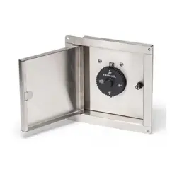
L-C2-760
ROBERT H. PETERSON CO. • 14724 East Proctor Avenue • City of Industry, CA 91746
INSTALLER: Leave these instructions with consumer.
CONSUMER: Retain for future reference.
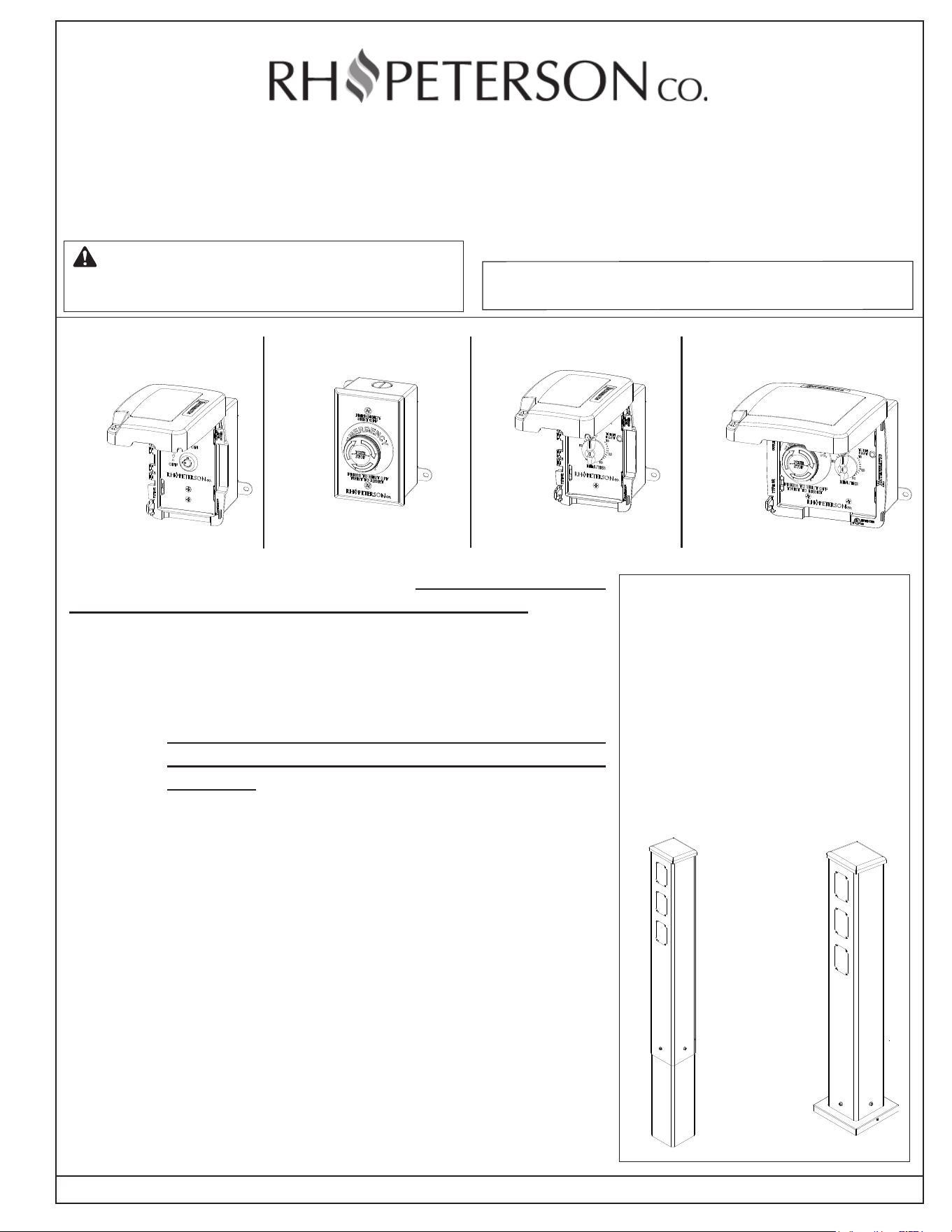
Outdoor Commercial Controls
Model #: 5550-110E, 5550-110S,
5531-11T, 5531-10K
These controls are intended for outdoor use. Observe all local codes
and ordinances when installing these electrical controls. If no local
codes are applicable, wiring MUST be in accordance with the latest
National Electric Code, ANSI/NFPA 70, or the Canadian Electrical Code,
CSA C22.1, whichever is applicable. Your individual installation may vary.
ELECTRICAL SETUP
Important: Electrical setup and installation of these outdoor
commercial controls MUST be performed by a licensed
electrician.
• TURN OFF THE MAIN ELECTRICAL SUPPLY TO THE
INSTALLATION LOCATION.
• Control(s) MUST be powered by a dedicated GFCI circuit breaker.
• Electrical supply must be rated for 110~120VAC (20 AMP maximum).
• Electrical wiring not supplied; use appropriate size copper conductors
only for your application.
• Check that the control device type and rating are suitable for
the appliance to be controlled.
IMPORTANT: USE COPPER CONDUCTORS ONLY. DO NOT
TIN THE CONDUCTORS. TAKE CAUTION THAT
THERE ARE NO STRAY WIRE STRANDS.
Model #
5550-110S
P/N 5550-110E
P/N 5531-11T
P/N 5550-110S
P/N 5531-10K
Emergency Stop
WARNING: Installation and service must be
performed by an NFI certied or other qualied
installer, service agency, or the gas supplier.
Emergency Stop &
Electric Timer
P/N 5550-110E
P/N 5531-11T
P/N 5550-110S
P/N 5531-10K
Model #
5531-10K
P/N 5550-110E
P/N 5531-11T
P/N 5550-110S
P/N 5531-10K
Model #
5531-11T
1-Hr Timer
P/N 5550-110E
P/N 5531-11T
P/N 5550-110S
P/N 5531-10K
Commercial Control Towers
(sold separately)
RHP outdoor commercial control
towers are available to accommodate
up to three (single-gang) control
boxes. The controls listed below
are compatible with this tower.
Contact your local dealer for ordering
information.
Model #:
POST-P
Model #:
POST-G
Compatable
with:
• 5531-10K
• 5550-110S
• 5531-11T
• Most single-
gang boxes
Model #
5550-110E
Master Key
Switch
2
REV 0 - D - 2601051415
L-C2-760
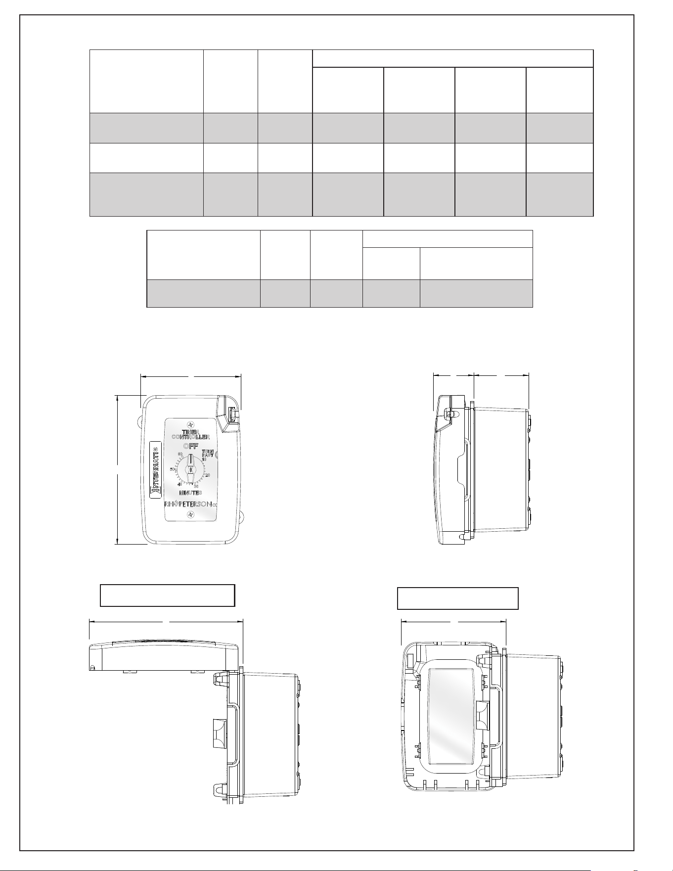
Fig. 2-1 Dimension Measurements
Table 2-1 Product dimensions
B
A
D
C
F
E
B
A
D
C
F
E
B
A
D
C
F
E
Model
Height
(A)
Width
(B)
Depth
Lid Closed
(C)
Switch Box
Housing
(D)
Lid Open
(Horizontal)
(E)
Lid Open
(Vertical)
(F)
Master Key Switch
(5531-10K)
5.5" 3.75" 1.5" 2" 5.75" 4"
1-Hr Timer
(5531-11T)
5.5" 3.75" 1.5" 2" 5.75" 4"
Emergency Stop &
Electric Timer
(5550-110E)
5.5" 5.6" 1.5" 2" 5.75" N / A
Model
Height
(A)
Width
(B)
Depth
Button*
(C)
Switch Box
Housing (D)
Emergency Stop
(5550-110S)
4.9" 3.1" 1.3" 2"
*Emergency stop button not shown.
PRODUCT DIMENSIONS
Vertical orientation
Horizontal orientation
3
REV 0 - D - 2601051415
L-C2-760
INSTALL SWITCH BOX
CAUTION: Ensure all electrical supply and gas (if applicable) is
OFF at the location of installation. The appliance must
be completely cool prior to any installation. Observe the
National Electric Code, the National Fuel Gas Code (NFPA
54), and all local codes.
1. Determine the best location for the control with a minimum distance of 6
feet away from the appliance to be controlled. The location must be at a
distance that supplies sucient voltage between the GFCI circuit breaker
and the receptacle.
Note: The control(s) can be mounted recessed into the wall or externally on
a wall's stable surface. Consider the location of wall studs for mounting
or any obstructions when planning for installation.
2. For IN-WALL RECESSED installation: cut a clearance hole at the
selected control switch location in preparation to mount the switch box.
Proceed to step 3.
For SURFACE-MOUNT installation: proceed to step 3.
For RHP outdoor commercial control tower installation: follow
the instructions provided with your post; then proceed to the MAKE
ELECTRICAL CONNECTIONS section below.
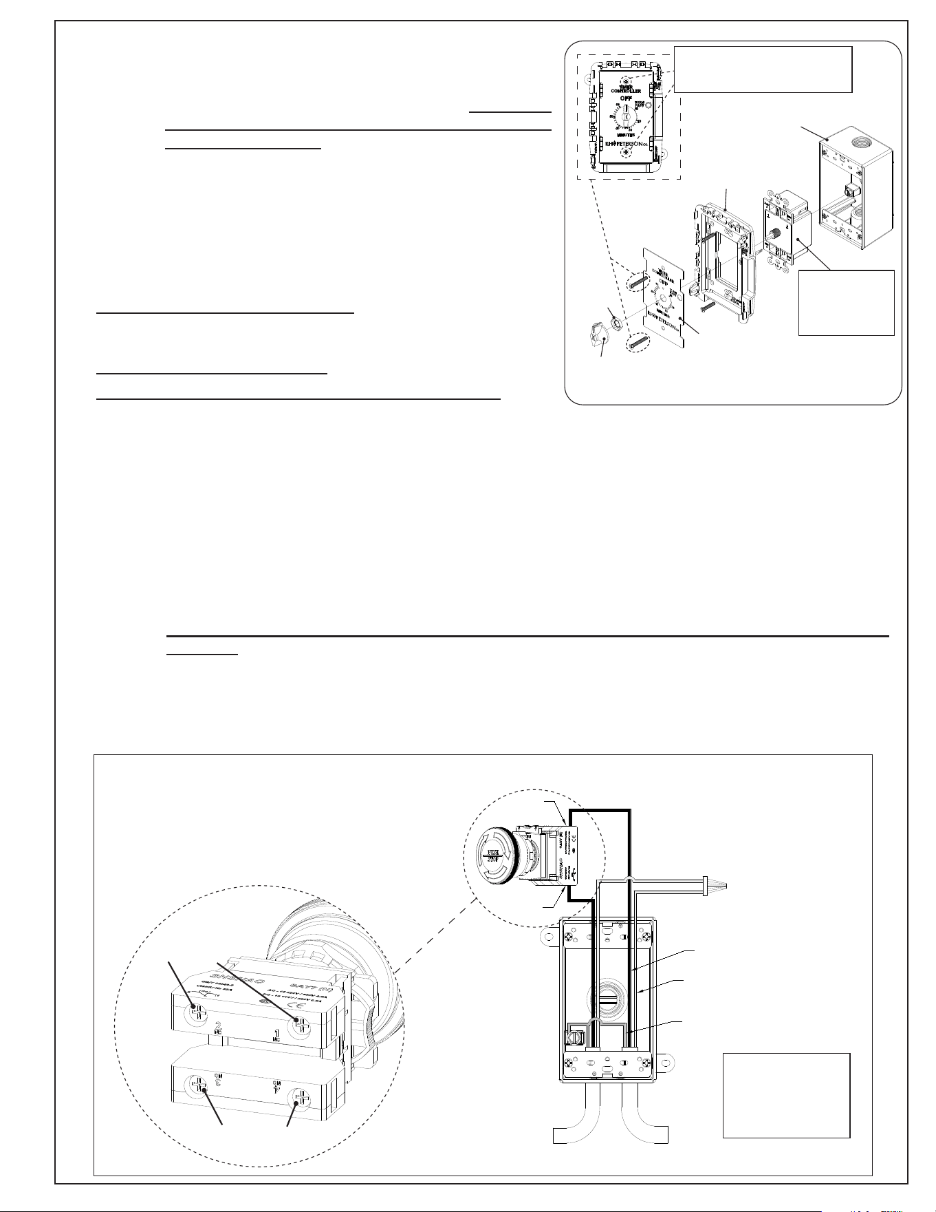
3. Using a Phillips-head screwdriver, remove the two screws and separate
the inner components from the switch box, leaving only the switch box
housing. See Fig. 3-1.
4. Use the provided brackets, if necessary, to securely mount the switch
box as applicable.
5. Run electrical wiring to the switch box housing as required for your
installation.
P/N 5550-110E
P/N 5531-11T
P/N 5550-110S
P/N 5531-10K
Front panel
Face plate
Nut
Timer knob
Fig. 3-1 Remove control screws
Remove screws (2-4) to
access inner components
Detach timer from
switch box housing
for 1-hr timer and
E-stop & electric
timer controls.
Switch box
housing
(1-Hr Timer shown, your control may vary)
MAKE ELECTRICAL CONNECTIONS
Important: All electrical setup and installation of these outdoor commercial controls MUST be performed by a licensed
electrician. USE COPPER CONDUCTORS ONLY. DO NOT TIN THE CONDUCTORS. TAKE CAUTION THAT
THERE ARE NO STRAY WIRE STRANDS.
1. Locate the appropriate wiring diagram for your control(s) below and on the following page. ENSURE TO FOLLOW THE
IMPORTANT INFORMATION PROVIDED FOR EACH CONTROL.
2. Make electrical connections as required, then proceed to the COMPLETE INSTALLATION section.
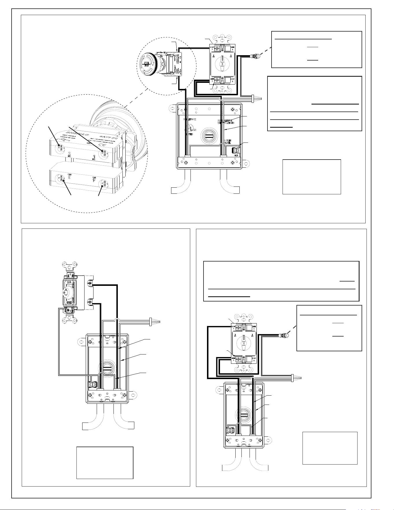
POWER
IN
POWER
TO
APPLIANCE
WHITE
BLACK
GREEN
(GROUND WIRE)
(NEUTRAL)
#1
NC
#2
NC
EMERGENCY STOP WIRE DIAGRAM
Black- Hot
White- Neutral
Green- Ground
The E-stop button oers connections to external
devices. NC (Normally Closed) is for the control
application, while NO (Normally Open) is for
optional devices (alarms, lights, etc.) that will
activate when button is pressed. See image below.
#1 NC
(Normally closed)
(Normally opened)
#4 NO#3 NO
#2 NC
4
REV 0 - D - 2601051415
L-C2-760
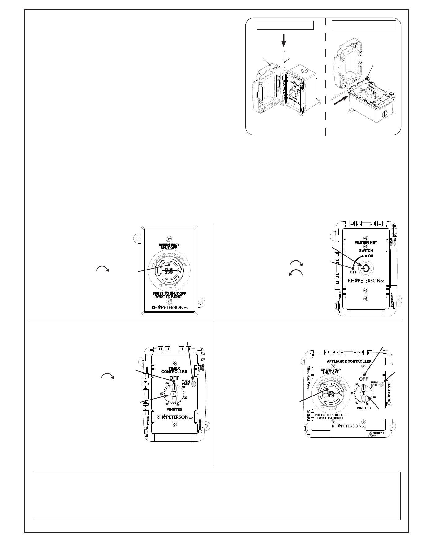
IMPORTANT:
IF INSTALLING WITH OTHER CONTROLS, This
electric timer control MUST be installed LAST
in the series.
LOAD 1
POWER
IN
POWER
TO
APPLIANCE
LINE 1
WHITE
GREEN
(GROUND WIRE)
(NEUTRAL)
#1
NC
#2
NC
BLACK
#1 NC
(Normally closed)
(Normally opened)
#4 NO#3 NO
#2 NC
EMERGENCY STOP & ELECTRIC TIMER WIRE DIAGRAM
WHITE
BLACK
GREEN
(GROUND WIRE)
(NEUTRAL)
POWER
IN
POWER
TO
APPLIANCE
MASTER KEY SWITCH
WIRE DIAGRAM
Black- Hot
White- Neutral
Green- Ground
LOAD 1
LINE 1
BLACK
WHITE
(NEUTRAL)
GREEN
(GROUND WIRE)
POWER
IN
POWER TO
APPLIANCE
1-HR TIMER
WIRE DIAGRAM
The E-stop button oers connections
to external devices. NC (Normally
Closed) is for the control application,
while NO (Normally Open) is for
optional devices (alarms, lights,
etc.) that will activate when button is
pressed. See image below.
Black- Hot
White- Neutral
Green- Ground
Black- Hot
White- Neutral
Green- Ground
IMPORTANT:
IF INSTALLING WITH OTHER
CONTROLS, This E-stop &
electric timer control MUST
be installed LAST in the
series.
LED indicator wires:
• one wire must be connected to
Line 1
• one wire must be connected to
neutral (white wire)
LED indicator wires:
• one wire must be
connected to Line 1
• one wire must be
connected to neutral
(white wire)
5
REV 0 - D - 2601051415
L-C2-760
P/N 5550-110E
P/N 5531-11T
P/N 5550-110S
P/N 5531-10K
COMPLETE INSTALLATION
Important: Inspect all wire connections and ensure wiring is
correct, fully secured, and there are no stray wire
strands.
1. Re-fasten all the inner components back into the switch box(es).
Note: For timer reinstallation, align the timer knob and press into
place.
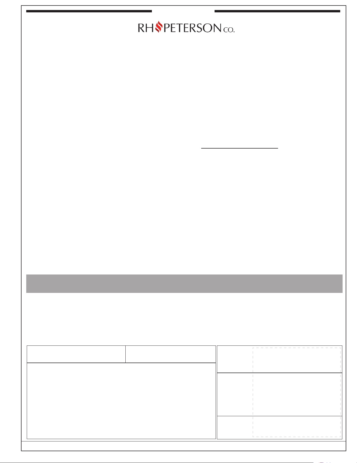
2. If applicable, you may install a control switch cover for added
protection. The protective cover can be positioned either
vertically or horizontally, allowing you to choose the orientation
best for your installation. See Fig. 5-1.
• If installing on an RH Peterson control tower (sold separately),
vertical orientation of the cover hinge is recommended.
• The E-stop & electric timer control switch cover can only be
installed horizontally.
3. Align the cover hinge with the corresponding hinge on the main
plate, then insert the provided pin to secure the assembly. See
Fig. 5-1.
4. Switch ON the electrical system and test the power to the unit.
See below for individual control operation information.
P/N 5550-110E
P/N 5531-11T
P/N 5550-110S
P/N 5531-10K
Press
for
OFF
position
Model
5550-110S
P/N 5550-110E
P/N 5531-11T
P/N 5550-110S
P/N 5531-10K
Model
5531-10K
Insert
key
OFF
position
Model
5531-11T
OFF
position
Timer
knob
Model
5550-110E
OFF
position
LED light
Press for
OFF position
Timer
knob
Master Key Switch
Use the provided key to turn
the power ON and OFF.
Insert the key and slightly
push inward to turn
clockwise to ON or
counterclockwise to OFF.
The key is removable in both
ON and OFF positions.
Emergency Stop
In case of an emergency,
press the red emergency
stop button to shut the
power OFF immediately.
Twist the stop button
clockwise to reset the
button and restore electrical
current to the unit.
Emergency Stop &
Electric Timer
This control integrates
two functions into a
single controller. See the
E-Stop and 1-hr Timer
for individual control
operation.
1-Hr Timer
When activated, the timer
will provide power to the
appliance for the selected
duration of time.
To use, turn the timer knob
past 10 minutes
clockwise (to activate timer),
then set to desired time. LED
indicator light will illuminate
indicating power is ON.
To stop the timer and turn
off the unit, turn the knob to
the OFF position until you
hear an audible click. LED
indicator light will turn off
indicating time has elapsed
and power is OFF.
OPERATION
Locate your outdoor commercial control below for the operation information.
Fig. 5-1 Attach protective cover
Vertical orientation Horizontal orientation
Cover
Retaining pin
Insert
Front panel
LED light
P/N 5550-110E
P/N 5531-11T
P/N 5550-110S
P/N 5531-10K
Note:
Harsh environments, wear, abuse, or tampering may aect your timer. It is recommended to periodically test the timer
at least once a month or as needed.
• Ensure when timer reaches the OFF position, there is no electrical current (red LED is o).
• If the timer does not shut o, have an electrician replace the timer.
6
R.H. Peterson Co. • 14724 East Proctor Avenue • City of Industry, CA 91746
Quality Check
Date:______________
Electrical Leak Test: __________________________
Operation Test: __________________________
Inspector: __________________________
Model #:
Serial #:
A COPY OF YOUR SALES SLIP FOR PROOF OF PURCHASE IS REQUIRED
This warranty applies to the original purchaser for products which are installed in the United States or Canada. This warranty is valid only with proof of purchase,
commences on the date of purchase, and terminates (both as to original and any replacement products) on the anniversary date of the original purchase of
the product per the above schedules.
This warranty does not cover parts which become defective as a result of negligence, misuse, or use not in compliance with the Installation and Owner’s
Manual, accidental damage, improper handling, improper storage, improper installation, lack of required routine maintenance (as specied in the Installation
and Owner’s Manual), electrical damage, local gas impurities or failure to protect against combustible materials. Product must be installed (and gas must be
connected) as specied in the Installation and Owner’s Manual by a qualied professional installer. This warranty does not apply to normal occurrences
that may be expected with any outdoor product such as rust, corrosion, oxidation, or discoloration unless the aected part becomes inoperable. RHP products
including valves, pilots and controls are designed and certied to be used as a system. Modications to products which are not specically authorized will
void this warranty and could render the product to be unsafe. Warrantied items will be repaired or replaced at RHP's sole discretion. This warranty does not
cover labor or labor related charges, except as provided by separate specic written programs from RHP. All repair work must be performed by a qualied
professional service person and requires prior approval of RHP.
RHP may require the defective product or part to be returned to the factory to determine the cause of failure. RHP will pay freight charges if the product or part
is determined to be defective. This warranty does not cover breakage in shipment from our independent distributor to its customer if the damage is determined
to have occurred during that shipment.
This warranty specically excludes liability for indirect, incidental, or consequential damages. Some states and provinces do not allow the exclusion or
limitation of incidental or consequential damages, so the above exclusion may not apply to you. This warranty gives you specied legal rights, and you may
have other rights that vary from state to state or province.
For additional information regarding this warranty, or to place a warranty claim, contact the RHP dealer where the product was purchased.
When contacting your RHP dealer or the R.H. Peterson Co., please provide the following information:
- Your name, address, telephone number, e-mail
- Sales receipt showing where purchased and date purchased
- Model number, serial number of product, date code
- Relevant information: installer, additions, repairs, when defect was rst noted
TO REGISTER YOUR PRODUCT ONLINE GO TO: WWW.RHPETERSON.COM,
AND CLICK ON PRODUCT REGISTRATION. THANK YOU FOR YOUR PURCHASE.
REV 0 - B - 2409111530
L-C2-726
COMMERCIAL / MULTI-USER LIMITED WARRANTY
When used in a commercial / multi-user setting* including but not limited to apartment complexes, multi-family dwelling complexes,
schools, hotels, re stations, police stations, etc.
*Excluding restaurants and other professional cooking settings.
R.H. Peterson Co. ("RHP") warrants your product to be free from defects in material and workmanship.
RHP
Stainless steel housings are warranted for FIVE (5) YEARS.
All other components, except batteries, are warranted for THREE (3) YEARS.
WARRANTY