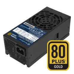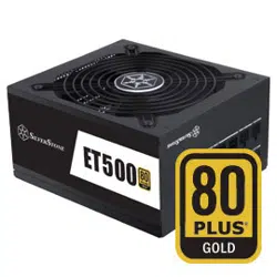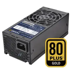

TX500 / TX700
TFX SERIES
The reference TFX power supply
500W / 700W continuous power output at 50°C operating temperature rated for 24/7 operation
High efficiency with 80 PLUS Gold certification
Silent running 80mm fan with 18 dBA minimum
Multiple protection circuitry
Single PCI-E 6+2pin connectors support

SPECIFICATION
TFX Form Factor
SST-TX500-G 500W
SST-TX700-G 700W
Switching Power Supply with
Active PFC
80Plus Gold
01
This document defines the Desktop Power Supply quality, 5 output 700W/500W,
power supplies for the application of Desktop systems.
key features:
The electrical specifications that follow is going to meet over the environmental
ranges specified in Section 3 unless otherwise noted.
1)Input: Full Range (90-264Vrms) with Active Power Factor Correction.
2)Output: Product is provided with a total of 5 output to meet the requirement of
ATX12V/EPS12V platform.
3)Cooling: A 80mm DC fan is used for cooling the power supply.
1.Scope
2. Electrical
•The inrush current is less than 130A under the conditions of 230Vrms input and 25 oC
ambient cold start. The inrush current is limited to the extent that no damage will be
done to the power supply under any specified line, load, and temperature conditions.
The inrush current will not cause external protection devices (fuses) to trip.
•The leakage current of the power supply module is less than 3.5mA measured at
230Vac input.
•The repetitive ON/OFF cycling of AC input voltage will not damage the power supply.
•The primary fuse is installed for input over-current protection, and meet product safety
requirement.
2.2.DC Output
The DC output voltages remain within the regulation ranges shown in Table 2.
when measured the at load end of the output connectors under all AC line,
O/P loads, and environmental conditions. The voltage regulation will be
maintained under continuous operation for a period of time equal to the MTBF
specified in section 5.2 at any steady state temperature and operating conditions
specified in section 3.
2.2.2. DC Output Load Distributions
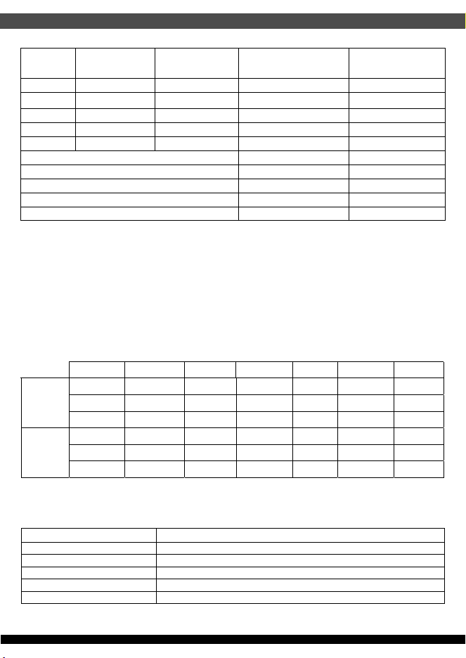
The Table 3. defines the power supply typical output load distribution.
Note: -12V at 0.3A maximum requires +12V rail to be loaded at 2A minimum.
02
Parameter Min Nominal Input Max Unit
V
in
Voltage
90 100-240 264 Vrms
V
in
Frequency
47 63 Hz
V
in
Current / 500W
8.0 A
V
in
Current / 700W
10.0 A
Power Factor(PF)
>0.95
at 230Vac input and full
Table 1. AC input
+12V +5V +3.3V -12V +5Vsb Unit
Total DC Output
Regulation
±5.0% ±5.0% ±5.0% ±10.0% ±5.0% Volt
Table 2. DC Output Voltage Regulations
2.1. AC Input
Table 1 lists AC input voltage and frequency range for continuous operation.
The power supply is capable of supplying full-rated output power over the input
voltage ranges as specified.
03
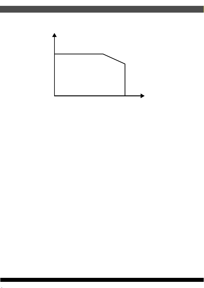
•Peak DC Output Power: 17 Seconds maximum, one occurrence maximum per minute
(115Vac 60Hz, 230Vac 50Hz).
Table 3. DC Output Load Distribution
Table 4. The power supply typical output load distribution
Table 5. The power supply typical output load distribution
In order to meet 2013 Erp* requirements, the following guidance must be met for the 5Vsb
efficiency at 230Vac.
Output
Rail
Output
Voltage
Minimum
Current (A)
700W
Max. (A)
500W
Max. (A)
V1 +12V 0.0 58.3 41.6
V2
+5V 0.0 22.0 18.0
V3 +3.3V 0.0 22.0 18.0
V4 -12V 0.0 0.3 0.3
V5 +5Vsb 0.0 2.5 2.5
Total Continuous Power
700W 500W
Max. combined O/P of V1
700W 500W
Peak DC Output Powe
770W 550W
Max. combined O/P of V2 & V3
120W 100W
Max. combined O/P of V4 & V5
16.1W 16.1W
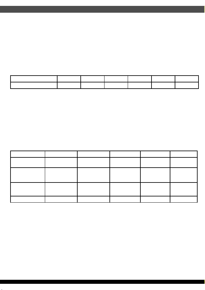
2.2.3. DC Output Efficiency
The power supply efficiency is 87% minimum measured at 20%, efficiency is 90%
minimum measured at 50%, , efficiency is 87% minimum measured at 100% which
is 115Vrms conditions. shown in Table 4.
LOAD +12V +5V +3.3V -12V +5VSB SPEC
700w
20%
9.77 A 2.4 2 A 2.4 2 A 0.05A 0. 4 2A
87%
50%
24.42 A 6. 05 A 6. 05 A 0.13A 1. 05 A 90%
100%
48.84 A 12. 10 A 12. 10 A 0.2 5A 2. 09 A 87%
500W
20%
6.76 A 1.96 A 1.96 A 0.05A 0.4 1A 87%
50%
16.91 A 4.89 A 4.89 A 0.12A 1. 01 A 90%
100%
33.81 A 9.78 A 9.78 A 0.24A 2. 03A 87%
Load on 5Vsb Efficiency
< 45mA AC input power should be <0.5W, including no load
45mA ≥ 50%
100mA ≥ 55%
250mA ≥ 65%
≥ 1A ≥ 75%
04
2.2.4. DC Output Ripple & Noise
The output ripple & noise specifications listed in Table 6. will meet throughout the load
ranges as specified in section 2.2.2 and the nominal line input voltage conditions as
specified in section 2.1. Ripple & noise is defined as periodic of random signals over
a frequency band of 10Hz to 20MHz. Measurements should be made with an
oscilloscope with 20MHz bandwidth. adding a 10uF electrolytic capacitor and a 0.1uF
ceramic capacitor across output terminal during ripple & noise measurement.
2.2.5. DC Output Transient Response
2.2.6. DC Output Voltage Hold-up Time
The output voltages will remain within the regulation limits specified in Table 2.
The load-changing repetition rate is 50Hz to 10KHz, and the transient load slew rate
1.0A/us. The maximum step load size, and output capacitive loading are specified as
followings in Table 7.
The power supply will maintain outputs in regulation per section 2.2.1 despite a loss of
input power at the nominal range of AC input and at 80% of maximum continuous
output load as applicable for a minimum of 10 msec.
+12V +5V +3.3V -12V +5Vsb Unit
Max Ripple & Noise
120 50 50 120 50 mV P-P
Table 6. DC Output Ripple & Noise
+12V +5V +3.3V -12V +5Vsb
Voltage limits.
±5% ±5% ±5% ±10% ±5%
Load Change
Low Load
2.0%~62% 0.0%~30% 0.0%~30% 0A ~ 0.1A 0A ~ 0.5A
Load Change
High Load
40%~100% 70%~100% 70%~100% 0.2A ~ 0.3A 2.0A ~ 2.5A
Capacitive Load 10000uF 10000uF 10000uF 470uF 3300uF
Table 7. DC Output Transient Response
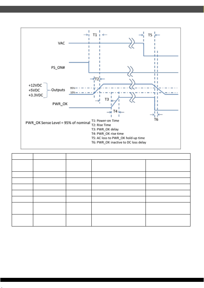
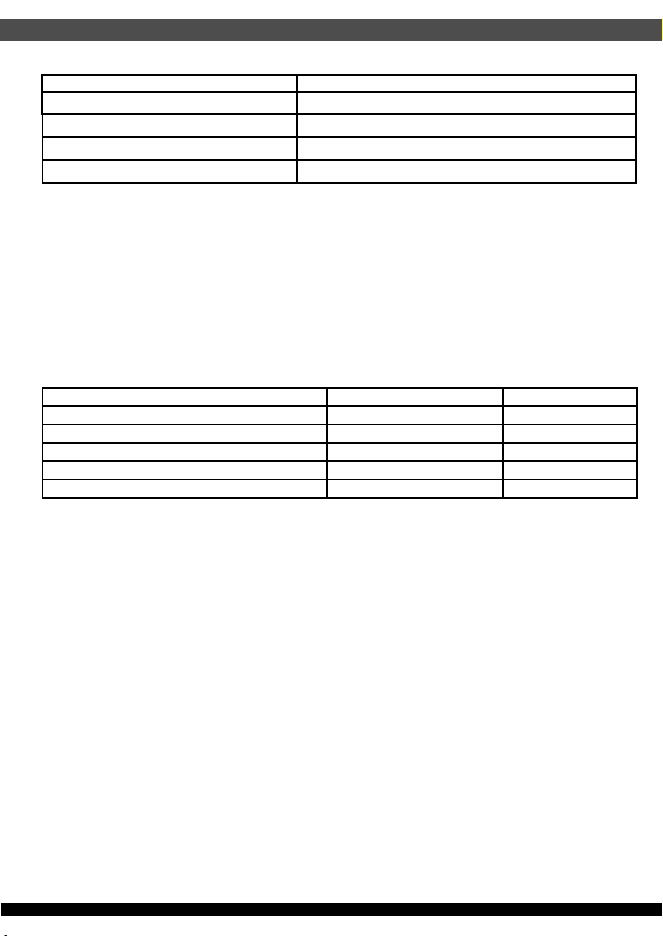
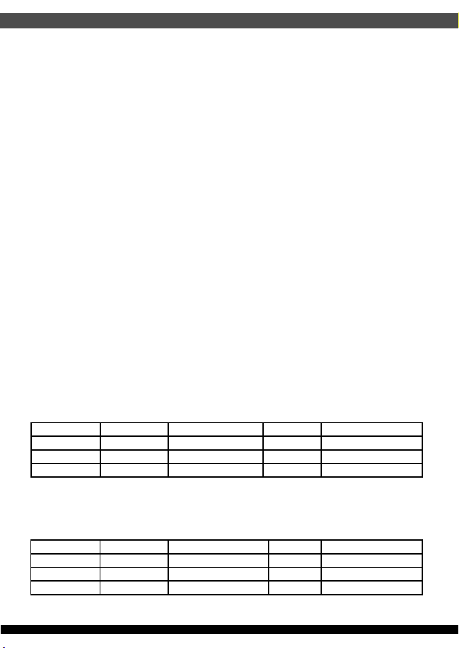
2.3.1. PWR_OK (Power Good Signal)
PWR_OK is a “power good” signal. It will be asserted high by the power supply to
indicate that the +5V output is above the under voltage threshold listed in Table 2. of
Section 2.2. PWR_OK will be de-asserted to a low state when +5V output voltage falls
below under voltage threshold, or when AC power has been removed for a time
sufficiently such that power supply operation cannot work normally. The electrical and
timing characteristics of the PWR_OK signal are given in Table 8. and in figure 1.
05
2.3. Timing / Housekeeping / control
Parameter Description Value
Required Recommended for
Non-Alternative Sleep Mode1
Recommended for
Alternative Sleep Mode
T0 AC power on time <2s
T1 Power-on time < 500ms < 200ms < 150ms
T2 Rise time 0.2 – 20 ms
T3 PWR_OK delay 100 – 500 ms 100 – 250 ms 100 – 150 ms
T4 PWR_OK rise time ≤ 10 ms
T5 AC loss to PWR_OK
hold-up time
≥ 10 ms (at 80% of maximum rated output
load)
T6 PWR_OK inactive to
DC loss delay
≥ 1 ms
06
2.3.2. PS_ON (DC Soft Start)
PS_ON# is an active-low, TTL-compatible signal that allows a motherboard to remotely
control the power supply in conjunction with features such as soft on/off, Wake on LAN*,
or wake-on-modem. When PS_ON# is pulled to TTL low, the power supply should turn
on the four main DC output rails: +12 VDC, +5 VDC, +3.3 VDC, and -12 VDC. When
PS_ON# is pulled to TTL high or open-circuited, the DC output rails should not deliver
current and should be held at zero potential with respect to ground. PS_ON# has no
effect on the +5VSB output, which is always enabled whenever the AC power is present.
Table 7 lists PS_ON signal characteristics.
2.3.3. +5Vsb (Standby Voltage Output)
+5Vsb is a standby voltage output that is active whenever the AC power is present.
It provides a power source for circuits that must remain operational when the four main
DC output rails are in a disabled state. Example uses include soft power control,
Wake on LAN, wake on modem, intrusion detection, or suspend state activities.
There is over current protection on the +5Vsb output to ensure the power supply will
not be damaged if external circuits draw more current than the supply can provide.
2.3.4. Power-on Time
The power-on time is defined as the time from when PS_ON is pulled low to when
the12V1, +5V, and +3.3V output are within the regulation ranges specified in
Section 2.2.1. The power-on time will be less than 150ms (T1 <150 ms). +5Vsb has
a power on time of two second max. after the valid AC Voltages applied.
2.3.5. Rise Time
The output voltage rise from ≤ 10% of nominal to within the regulation ranges specified
in section 2.2.1 within 0.1 ms to 20 ms (0.1 ms ≤ T2 ≤ 20 ms)
Signal type +5V TTL compatible
Logic level low
< 0.4 V while sinking 4 mA
Logic level high
Between 2.4 V and 5 V output while sourcing 200 μA
High-state output impedance
1 kΩ from output to common
Max Ripple/Noise 400 mV p-p
Table 8. PWR_OK Signal Characteristics
Min Max
V
IL
, Input Low Voltage 0.0V 1.5V
I
IL
, Input Low Current (Vin = 0.4V) -1.6mA
V
IH
, Input high Voltage (lin = -200uA) 2.4V
V
IH
, open circuit, lin =0 -5.25V
Ripple/Noise 400 mV p-p
Table 9. PS_ON Signal Characteristics
2.3.6. PWR_OK (Power Good Signal)
The +12V and +5V output levels are equal to or greater than the +3.3V output at all
times during power-up and normal operation. The time between the +12V or +5V
output reaching its minimum in-regulation level and +3.3V reaching its minimum
in-regulation level is ≤ 20 msec.
2.3.7. Overshoot at Turn-on / Turn-off
The output voltage overshoot upon the application or removal of the input voltage,
or the assertion / de-assertion of PS_ON will be less than 10% above the nominal
voltage.
2.3.8. Reset after Shutdown
If the power supply latches into a shutdown state because of a fault condition on its
outputs, the power supply can return to normal operation only after the fault condition
has been removed and the PS_ON has been cycled OFF/ON with a minimum OFF
time of 1 second.
2.3.9. +5Vsb at AC Power-down
2.4.1. Over Voltage Protection
After AC power is removed, the +5Vsb standby voltage output will remain at its steady
state value for the minimum hold-up time specified in Section 2.2.6 until the output
begins to decrease in voltage. The decrease can be monotonic in nature, dropping to
0.0V. There are no other perturbations of this voltage at or following removal of
AC power.
2.4. Output Protection
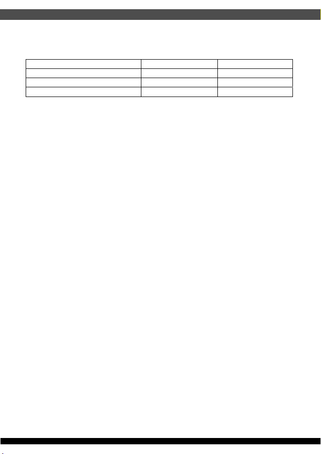
The power supply can provide latch-mode over voltage protection as defined in
Table 10.
2.4.2. Under Voltage Protection
The power supply can provide latch-mode Under voltage protection as defined in
Table 11.
07
Output Min. Nom. Max. Unit
+12VDC 13.6 14.6 17 Volts
+5VDC 5.5 6.25 7.0 Volts
+3.3VDC 3.7 4.1 4.7 Volts
Table 10. Over Voltage Protection
Output Min. Nom. Max. Unit
+12VDC 8.80 9.30 9.80 Volts
+5VDC 4.0 4.30 4.47 Volts
+3.3VDC 2.5 2.69 2.83 Volts
Table 11. Under Voltage Protection
08
2.4.3. Over Current Protection
The power supply can provide Over Current Protection as defined in Table 12.
Table 12. Over Current Protection
2.4.4. Short-circuit Protection
The power supply will shut down and latch off for shorting the +12V, +5V, +3.3V, and
-12V rails to return or any other rails. Shorts between main output rails and +5Vsb will
not cause any damage to power supply. +5Vsb can be capable of being shorted
indefinitely, but when the short is removed, the power supply will recover automatically
or by cycling PS_ON. The power supply can be capable of withstanding a continuous
short circuit to the output without damage or overstress to the unit under the input
conditions specified in section 2.1.
2.4.5. Over Power Protection
Fold back at 115%~150% over peak load
>55 degree Celsius ambient at full load <70 degree Celsius ambient at full load. Latch
off protection with AC line or PWR_ON reset.
2.4.6. OVER TEMPERATURE PROTECTION
No damage or hazardous condition will occur with all the DC output connectors
disconnected from the load. The power supply may latch into the shutdown state.
2.4.7. No-load Operation
The following subsections define recommended environmental specifications and test
parameters. Based on the typical conditions to which an ATX 12V power supply may be
subjected during operation or shipment.
1800Vac for 1 minute
2.4.8. Isolation (High Voltage Withstand)
Output Min. Max.
+12VDC 115% 150%
+5VDC 30A 50A
+3.3VDC 30A 50A
3. Environmental
Operating 0°C to +50°C
Non-operating -20°C to +70°C
Operating 20% to 90% relative humidity (non-condensing)
Non-operating 5% to 95% relative humidity (non-condensing)
3.1. Temperature
09
3.2. Humidity
Operating 0 to 10,000 feet
Storage 0 to 50,000 feet
3.3. Altitude
The following subsections outline applicable product regulatory specifications for
this power supply.
The power supply can comply with FCC Part 15 and EN55032: 2015 meeting
Class B for both conducted and radiated emissions with a 3 dB margin.
4.1. Emissions (Meet)
The power supply can comply with EN 55035: 2017.
4.2. Immunity (Meet)
4. Electromagnetic Compatibility
WATT
100% full load
80% full load
0deg 10deg 20deg 30deg 40deg 50deg
TEMP
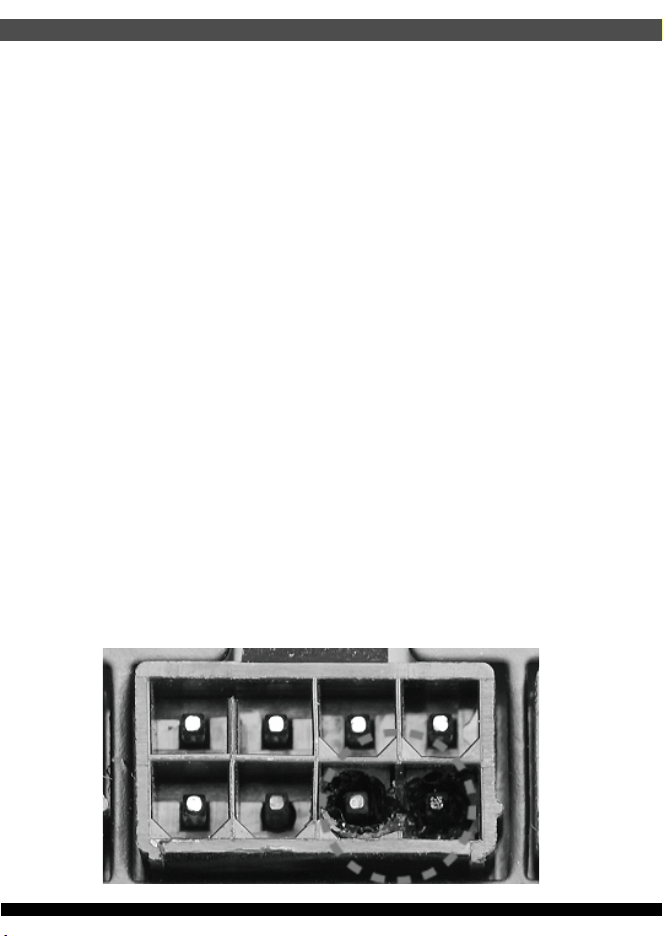
7. POWER SUPPLY CONNECTOR OVERUSE DEFINITION
10
4.3. CE Testing (Meet)
The following standards are applied during the CE testing
EN 55032: 2015 Class B with 3dB margin minimum
EN 61000-3-2: 2014 Harmonic Current Measurement
EN 61000-3-3: 2013 Voltage Fluctuation and Flick Measurement
EN 55035: 2017, including
IEC 61000-4-2: 2009 ESD – air discharge 8kV / ESD contact discharge 4kV
IEC 61000-4-3: 2010 Radiated, Radio Frequency Electromagnetic Field
Immunity Test
IEC 61000-4-4: 2012 Electrical Fast Transient/Burst Immunity Test
IEC 61000-4-5: 2014 Surge Immunity Test – 2kV L/N to PE and 1kV L to N
IEC 61000-4-6: 2014 Immunity to Conducted Disturbances Induced by RF Fields
IEC 61000-4-8: 2010 Power Frequency Magnetic Field Immunity Test
IEC 61000-4-11: 2004 Voltage Dips and Short Interruptions Immunity Test
The derating process promotes quality and high reliability. All electronic components
are designed with conservative derating for use in commercial and industrial
environments.
5.1. Component De-rating
Dimension W x L x H = 85 x 175 x 65mm.
5.2. Mean Time between Failures (MTBF)
100K hours minimum at full load 25
°C
5. Reliability
6. Mechanical
11
Power supply connector overuse definition
EN
A single PCIe 8pin cable and connector’s maximum current rating is
12.5A, which is 150W (+12V x 12.5A). So SilverStone’s warranty will
not cover damages or malfunction resulting from the use of a graphics
card or expansion card with a single PCIe 8pin connector that exceeds
standard 225W total power draw (150W from PCIe 8pin connector +
75W from PCIe motherboard slot). Similarly, a graphics card or
expansion card with dual PCIe 8pin connectors that exceed 375W total
power draw (300W from two PCIe 8pin connectors + 75W from PCIe
motherboard slot) will also not be covered under warranty.
Peripheral (molex) or SATA connector’s maximum current rating is 5A,
which is 60W (+12V x 5A) or 25W (+5V x 5A). Please ensure
connected devices are operating under these limits. SilverStone’s
warranty will not cover damages or malfunction resulting from usages
exceeding these connectors and their associated cables.
24pin motherboard connector’s maximum current rating for its dual
+12V metal pins are 5A each, which totals 120W (+12V x 5A x 2).
Please ensure +12V drawing devices connected to the motherboard
are operating under these limits. SilverStone’s warranty will not cover
damages or malfunction resulting from usages exceeding these
connectors and their associated cables.
Definition einer Überlastung des
Netzanschlusses
DE
Die maximale Stromstärke eines einzelnen 8-poligen PCIe-Kabels und
Anschlusses beträgt 12,5 A, was 150 W (+12 V x 12,5 A) entspricht.
Daher deckt die SilverStone-Garantie keine Schäden oder
Fehlfunktionen durch den Einsatz einer Grafikkarte oder
Erweiterungskarte mit einem einzigen 8-poligen PCIe-Anschluss ab,
die die Standardleistungsaufnahme von insgesamt 225 W übersteigt
(150 W vom 8-poligen PCIe-Anschluss + 75 W vom
PCIe-Motherboard-Steckplatz). Ebenso wird die Verwendung einer
Grafikkarte oder Erweiterungskarte mit zwei 8-poligen
PCIe-Anschlüssen, die eine Leistungsaufnahme von insgesamt 375
übersteigen (300 W von den beiden 8-poligen PCIe-Anschlüssen + 75
W vom PCIe-Motherboard-Steckplatz) nicht durch die Garantie
abgedeckt.
Der maximale Nennstrom von Peripherie- (Molex) oder
SATA-Anschluss beträgt 5 A, was 60 W (+12 V x 5 A) oder 25 W (+5 V
x 5 A) entspricht. Bitte achten Sie darauf, dass verbundene Geräte
unter diesen Grenzwerten arbeiten. Die Garantie von SilverStone
deckt keine Schäden oder Fehlfunktionen aufgrund einer Nutzung ab,
die diese Anschlüsse und ihre zugehörigen Kabel übersteigt.
Der maximale Nennstrom des 24-poligen Motherboard-Anschlusses
für seine dualen +12-V-Metallkontakte beträgt jeweils 5 A, was
insgesamt 120 W (+12 V x 5 A x 2) ergibt. Bitte stellen Sie sicher, dass
mit dem Motherboard verbundene +12-V-Geräte unter diesen
Grenzwerten arbeiten. SilverStones Garantie deckt keine Schäden
oder Fehlfunktionen aufgrund einer Nutzung jenseits der Angaben
dieser Anschlüsse und ihrer zugehörigen Kabel ab.
Définition de l'utilisation excessive du
connecteur d'alimentation électrique
FR
Le courant nominal maximum d'un câble et d'un connecteur PCIe 8
broches unique est de 12,5 A, ce qui correspond à 150 W (+12 V x 12,5
A). La garantie de SilverStone ne couvre donc pas les dommages ou
les dysfonctionnements résultant de l'utilisation d'une carte graphique
ou d'une carte d'extension avec un connecteur PCIe 8 broches unique
qui dépasse une consommation énergétique totale de 225 W standard
(150 W provenant du connecteur PCIe 8 broches + 75 W provenant de
l'emplacement de la carte mère PCIe). De même, une carte graphique
ou une carte d'extension avec deux connecteurs PCIe 8 broches qui
dépasse une consommation énergétique totale de 375 W (300 W
provenant des deux connecteurs PCIe 8 broches + 75 W provenant de
l'emplacement de la carte mère PCIe) ne sera également pas couverte
dans le cadre de la garantie.
Le courant nominal maximum d'un périphérique (Molex) ou d'un
connecteur SATA est de 5 A, ce qui correspond à 60 W (+12 V x 5
A) ou 25 W (+5 V x 5 A). Veuillez vous assurer que les appareils
connectés fonctionnent dans ces limites. La garantie de SilverStone
ne couvre pas les dommages ou les dysfonctionnements résultant
d'utilisations dépassant ces connecteurs et leurs câbles associés.
Le courant nominal maximal des connecteurs 24 broches de la
carte mère pour ses doubles broches métalliques +12 V est de 5 A
chacun, ce qui représente au total 120 W (+12 V x 5 A x 2). Veuillez
vous assurer que les dispositifs de tension +12 V connectés à la
carte mère fonctionnent dans ces limites. La garantie de
SilverStone ne couvre pas les dommages ou les
dysfonctionnements résultant d'utilisations dépassant la capacité de
ces connecteurs et de leurs câbles associés.
La corrente massima di un singolo cavo PCIe a 8 pin e del
connettore è 12,5 A, corrispondente a 150 W (+12 V x 12,5 A).
Pertanto, la garanzia di SilverStone non copre danni o
malfunzionamenti derivanti dall'utilizzo di una scheda grafica o una
scheda di espansione con un singolo connettore PCIe a 8 pin che
supera l'assorbimento totale di 225 W (150 W da connettore PCIe a
8 pin + 75 W da slot PCIe). Analogamente, la garanzia non copre
anche una scheda grafica o una scheda di espansione con doppi
connettori PCIe a 8 pin che superano l'assorbimento totale di 375
W (300 W da doppi connettori PCIe a 8 pin + 75 W dalla scheda
madre PCIe).
La corrente massima del connettore periferico (molex) o SATA è 5
A, corrispondente a 60 W (+12 V x 5 A) o 25 W (+5 V x 5 A).
Assicurarsi che i dispositivi collegati funzionino entro questi limiti. La
garanzia di SilverStone non copre danni o malfunzionamenti
derivanti da uso eccessivo di questi connettori e dei relativi cavi.
La corrente massima del connettore a 24 pin per scheda madre per
i suoi due pin di metallo a +12 V è di 5 A ciascuno, per un totale di
120 W (+12 V x 5 A x 2). Assicurarsi che i dispositivi a +12 V
collegati alla scheda madre funzionino con questi limiti. La garanzia
di SilverStone non copre danni o malfunzionamenti derivanti da uso
eccessivo di questi connettori e dei relativi cavi.
Definizione di uso eccessivo del connettore
di alimentazione
IT
La corriente máxima de un solo cable PCIe de 8 pines es 12,5A, lo
que son 150W (+12V x 12,5A). Por tanto, la garantía de SilverStone
no cubrirá daños o fallos provocados por el uso de una tarjeta gráfica
o de expansión con un único conector PCIe de 8 pines que exceda el
total estándar de 225W (150W del conector PCIe de 8 pines + 75W
del zócalo PCIe de la placa base). De igual modo, una tarjeta gráfica
o de expansión con conectores duales PCIe de 8 pines que superen
375W de potencia (300W de los dos conectores PCIe de 8 pines +
75W del zócalo de la placa base) tampoco será cubierta por la
garantía.
La corriente máxima del conector de periféricos (molex) o SATA es
5A, que son 60W (+12V x 5A) o 25W (+5V x 5A). Por favor,
asegúrese de que los dispositivos conectados funcionan dentro de
estos límites. La garantía de SilverStone no cubrirá daños o fallos a
resultas de un uso excesivo de estos conectores y sus cables
asociados.
La corriente máxima del conector de 24 pines de la placa base para
sus pines de metal duales de +12V es de 5A cada uno, para un total
de 120W (+12V x 5A x 2). Por favor, asegúrese de que los
dispositivos de +12V conectados a la placa base funcionan dentro de
estos límites. La garantía de SilverStone no cubrirá daños o averías a
resultas de un uso excesivo para estos conectores y sus cables
asociados.
Definición de uso excesivo del conector de
la Fuente de alimentación
ES

12
Определение чрезмерной нагрузки на
коннектор блока питания
RU
전원 공급 커넥터 과용 정의
KR
Один кабель и коннектор PCIe 8pin поддерживает ток 12.5A, что
равно 150Вт (+12В x 12.5A). Таким образом, гарантийные
обязательства SilverStone не будут действовать если вы
используете видеокарту или другую карту расширения с одним
коннектором PCIe 8pin, которые превышает стандартную общую
потребляемую мощность 225Вт (150Вт через коннектор PCIe 8pin
+ 75Вт через слот PCIe материнской платы). Аналогично,
видеокарта или другая карта расширения с
двумя коннекторами
PCIe 8pin, которые превышают общую потребляемую мощность
375Вт (300Вт через коннектор PCIe 8pin + 75Вт через слот PCIe
материнской платы), также не будут покрываться гарантией.
Максимальный номинальный ток периферийного (molex) или
SATA разъёма составляет 5A, что равно 60Вт (+12В x 5A) или 25
Вт (+5В x 5A). Пожалуйста, убедитесь, что подключенные
устройства работают в этих пределах. Гарантия SilverStone не
будет распространяться на
неисправности, возникающие в
результате использования этих коннекторов или подключаемых к
ним кабелей.
Максимальный номинальный ток 24pin коннектора материнской
платы для его двойных металлических контактов +12В составляет
5A на каждый, что равно 120Вт (+12В x 5A x 2). Пожалуйста,
убедитесь, что устройства, подключенные к линии +12В, работают
в этих пределах. Гарантия SilverStone не будет распространяться
на неисправности, возникающие
в результате использования этих
коннекторов или подключаемых к ним кабелей.
단일한 PCIe 8핀 케이블 및 커넥터의 최대 전류 정격은 12.5A로서
전력으로 환산하면 150W(+12V x 12.5A)입니다. SilverStone의
보증에서는 표준 225W의 총 소비 전력 (PCIe 8핀 커넥터의 150W와
PCIe 메인보드 슬롯의 75W의 합)을 초과하는 단일 PCIe 8핀 커넥터
탑재 그래픽 카드나 확장 카드를 사용하여 발생하는 손상 또는
오작동을 보상하지 않습니다. 이와 마찬가지로 375W의 총 소비
전력(PCIe 8핀 커넥터 2개의 300W와 PCIe 메인보드 슬롯의 75W의
합)을 초과하는 듀얼 PCIe 8핀 커넥터 탑재 그래픽 카드나 확장
카드를 사용해도 보증에서 보상해주지 않습니다.
주변장치(molex) 또는 SATA 커넥터의 최대 전류 정격은 5A로서
전력으로 환산하면 60W(+12V x 5A) 또는 25W(+5V x 5A)입니다.
연결된 장치들은 이러한 제한 하에서만 작동시켜야 합니다.
SilverStone의 보증에서는 이러한 커넥터 및 이와 연결되는 케이블의
정격을 초과하여 사용함으로써 발생하는 손상이나 오작동을 보상하지
않습니다.
듀얼 +12V 금속 핀에 사용되는 24핀 메인보드 커넥터의 정격 전류는
5A 이며, 각각 합계가 120W (+12V x 5A x 2) 입니다. 메인보드에
연결된 +12V 장치가 해당 한계 미만으로 작동되도록 하십시오.
SilverStone은 이 커넥터나 관련 케이블의 한계를 초과해서
사용함으로써 발생하는 손상이나 고장에 대해서 보장하지 않습니다.
单条PCIe 8pin电源线与接头的最大额定电流为12.5A,瓦特数150W(
+ 12V x 12.5A)。 因此,银欣的电源保固不包括用于单条PCIe
8pin接头之显卡/扩充卡,在超过标准225W总功耗范围所造成的损坏
或故障(150W 的PCIe 8pin接头+ 75W的主板PCIe插槽)。 以此类推
,若具备双PCIe 8pin接头的显卡/扩充卡,负载一但超过375W总功耗
,视同不属保固范围内(300W来自两个PCIe 8pin接头 + 75W的主板
PCIe插槽)。
大4pin(molex)或SATA接头的最大额定电流为5A,即60W(+ 12V x
5A)或25W(+ 5V x 5A)。 请确保连接的设备皆低于此限制下运行
。
银欣不保固超出电源供应器接头及其相关线材之使用负载上限所造成
的损坏或故障。
24pin主板接头的双+12V金属针脚最大额定电流为5A,即120W(+ 12V
x 5A x 2)。请确保连接的+12V设备皆低于此限制下运行。
银欣不保固超出电源供应器接头及其相关线材之使用负载上限所造成
的损坏或故障。
単一のPCIe8ピンケーブルおよびコネクタの最大定格電流は12.5Aで
150W(+12Vx12.5A)となります。それで定格225W合計電力消費(PCIe
8ピンコネクタからの150W+PCIeマザーボードスロットからの75W)
を超える、単一PCIe8ピンコネクタ装備のグラフィックスカードまたは
拡張カード使用によって生じた損傷や故障の場合、SilverStoneの製品
保証は適用外となります。同様に、375W合計電力消費(2基のPCIe8ピ
ンコネクタからの300W+PCIeマザーボードスロットからの75W)を超
える、デュアルPCIe8ピンコネクタ装備のグラフィックスカードまたは
拡張カード使用によって生じた損傷や故障の場合も、製品保証適用外
となります。
周辺用(molex)またはSATAコネクタの最大定格電流は5Aで、60W
(+12Vx5A)または25W(+5Vx5A)となります。接続された装置がこれら
限度以内で動作することを確認してください。これらコネクタおよび関
連ケーブルの定格を超える使用法で生じた損傷や故障については、
SilverStone製品保証対象外となりますのでご注意ください。
24ピンマザーボードコネクタのデュアル+12V金属製ピンに対する最大
定格電流はそれぞれ5Aなので合計は120W(+12Vx5Ax2)となります。
接続される+12V入力のデバイスが、これら上限以内で動作することを
ご確認ください。これらコネクタおよび関連ケーブルでの限界を超えた
使用で生じた損傷または故障は、SilverStoneによる製品保証対象外と
なります。
电源供应器接头过度使用定义
CN
電源供應器接頭過度使用定義
TW
單條PCIe 8pin電源線與接頭的最大額定電流為12.5A,瓦特數150W
(+ 12V x 12.5A)。 因此,銀欣的電源保固不包括用於單條PCIe
8pin接頭之顯卡/擴充卡,在超過標準225W總功耗範圍所造成的損壞
或故障(150W 的PCIe 8pin接頭+ 75W的主機板PCIe插槽)。 以此
類推,若具備雙PCIe 8pin接頭的顯卡/擴充卡,負載一但超過375W
總功耗,視同不屬保固範圍內(300W來自兩個PCIe 8pin接頭 + 75W
的主機板PCIe插槽)。
大4pin(molex)或SATA接頭的最大額定電流為5A,即60W(+ 12V x
5A)或25W(+ 5V x 5A)。 請確保連接的設備皆低於此限制下運行
。
銀欣不保固超出電源供應器接頭及其相關線材之使用負載上限所造
成的損壞或故障。
24pin主機板接頭的雙+12V金屬針腳最大額定電流為5A,即120W(+
12V x 5A x 2)。請確保連接的+12V設備皆低於此限制下運行。
銀欣不保固超出電源供應器接頭及其相關線材之使用負載上限所造
成的損壞或故障。
電力供給コネクタの使用限度超過に関する説明
JP
13
ขีดจำกัดการรองรับการใช้งานของขั้วต่อจากพาวเวอร์ซัพพลาย
TH
สำหรับขั้วเชื่อมต่อและสายไฟเลี้ยง PCIe 8 พินสามารถรองรับกระแสได้สูงสุด 12.5 แอมป์หรือหมายถึง 150 วัตต์
(+12V x 12.5A) ดังนั้นการรับประกันจากทาง SilverStone จะไม่ครอบคลุมถึงความเสียหายหรือความผิดปรกติซึ่งเกิดขึ้นกับกราฟิกการ์ดรวมถึงการ์ดขยายความยาวที่ใช้งานขั้วเชื่อมต่อ PCIe 8 พิน ซึ่งมันมีการใช้พลังงานรวมทั้งสิ้นเกินกว่ามาตรฐานที่กำหนดคือ 225 วัตต์ (150
วัตต์ จาก PCIe 8 พิน + 75 วัตต์ จากสล๊อต PCIe บนเมนบอร์ด) อันรวมถึงกราฟิการ์ดหรือการ์ดขยายความยาวที่ใช้ขั้วต่อไฟเลี้ยง PCIe 8 พ
ินจำนวน 2 ชุดซึ่งมีการใช้พลังงานทั้งสิ้น 375 วัตต์ (300 วัตต์ จากขั้ว PCIe 8 พิน 2 ชุด + 75 วัตต์ จากสล๊อต PCIe
บนเมนบอร์ด) ซึ่งไม่ครอบคลุมเช่นกัน
ภายใต้การรับประกัน ขั้วเชื่อมต่อ Peripheral หรือ Molex 4 พินและ SATA มันสามารถรองรับกระแสได้สูงสุด 5 แอมป์หรือหมายถึง 60 วัตต์ (+12V x 5A) หรือ (+5V + 5A) กรุณาให้แน่ใจว่าอุปกรณ์ที่ใช้งานมีการใช้พลังงานไม่เกินกว่าขีดจำกัดที่รองรับ
ดังนั้นการรับประกั
นจากทาง SilverStone จะไม่ครอบคลุมถึงความเสียหายหรือความผิดปรกติจากอุปกรณ์ที่เชื่อมต่อใช้งานจากตัวสายเชื่อมต่อซึ่งมีการใช้พลังงานเกินกว่าขีดจำกัด
กระแสไฟฟ้าสูงสุดของขั้วต่อเมนบอร์ด 24 พิน สำหรับพินโลหะ +12V คู่แต่ละอันมีค่า 5A ซึ่งรวมทั้งหมดเป็น 120W
(+12V x 5A x 2) โปรดตรวจสอบให้มั่นใจว่าอุปกรณ์ตัวดึงพลังงาน +12V ที่เชื่อมต่อกับเมนบอร์ดสามารถทำงานภายใต้ขีดจำกัดเหล่านี้ได้ การรับประกันของ SilverStone ไม่คุ้มครองความเสียหาย
หรืออาการเสียที่เป็นผลจากการใช้เกินขีดจำกัดของขั้วต่อและสายเคเบิลที่ใช้เชื่อมต่อเหล่านี้
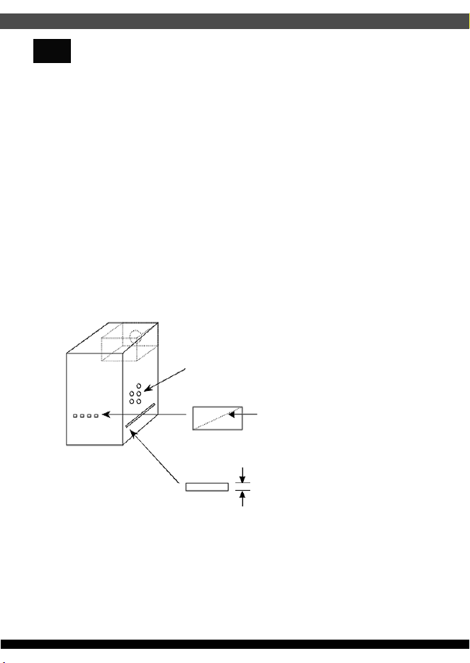
1. 為了保護使用者及防火的目的,安裝此交換式電源供應器時,必須安裝於符合下列各項要求的外殼中,
並且安裝妥善後,才可接上電源。
1-1. 外殼材質須為防火外殼。外壳材质须为防火外壳。
1-2. 外殼的上方及側邊之圓形開孔,最大內徑不可大於5mm。
1-3. 外殼的上方及側邊之長條型開孔,對角線距離不可大於5mm;若寬度小於1mm,則長度不受限制。
1-4. 外殼底部不可有開孔。外壳底部不可有开孔。
直徑不大於5mm
對角線不大於5mm
寬度小於1mm 則長度不限
Openings that do not exceed 1mm in width regardless of length
Openings that do not exceed 5mm in any dimension
2. 本產品輸出含有危險能量,為避免操作時發生危險,須於裝入系統機殼並將所有設備安裝妥當後才可開啟電源。
3. 本產品之電源輸出非屬電力限制型電源,請連接使用具防火外殼之周邊,以避免火災危險發生。
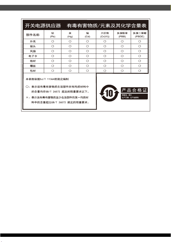
BSMI ROHS 資訊
http://www.silverstonetek.com/downloads/PSU/RSD.pdf
14
This device complies with Part 15 of the FCC Rules.
Operation is subject to the following two conditions:
(1) this device may not cause harmful interference, and
(2) this device must accept any interference received,
including interference that may cause undesired operation.
Please refer to SilverStone website for latest specifications updates.
※付属の電源コードは当該製品専用です。他の機器に使用しないでください。
G11240030