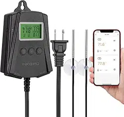
Plug and Play Temperature
Controller
(English)
support

What is ITC-308?
ITC-308 is an easy-to-use, safe and reliable dual relay
output temperature controller. It can be used as over-
temperature protection and automatic temperature
control system for various electric appliances such as
equipment for home-brew, aquarium, pet breeding,
incubation, BBQ, seedling heat mats, oven temperature
control, terrestrial heat control, constant temperature
cycle of heating pump, culture fermentation, accelerating
germination, electric radiator, electric oven, etc.
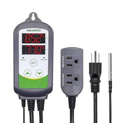
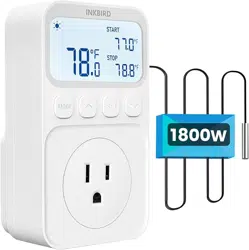
This product has plug-n-play de
sign with dual relay, be
able to connect with refrigeration and heating equipment
easily to realize ideal temperature control. It's equipped
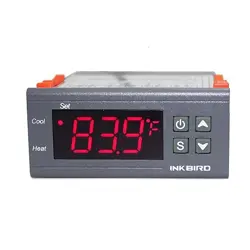
with dual LED display, and offers display options of
Centigrade and Fahrenheit, enabling more humanized
temperature control. With large output power 1200W
(110V) / 2200W(220V), it's suitable for most applications.
Ensure the product using within the specification.
Do not touch the terminals at least while power is being
supplied. Doing so may occasionally result in injury due
to electric shock.
Do not allow pie
ces of metal, wire clippings, or fine
metallic shaving or filings from installation to enter the
product. Doing so may occasionally result in electric
shock, fire, or malfunction.
Do not use the product where subject to flammable or
explosive gas. Otherwise, injury from explosion may
occasionally occur.
Never disassemble, modify or repair the product or
touch any of the internal parts. Electric Shock, fire, or
malfunction may occasionally occur.
If the output relays are used over their life expectancy,
contact fusing or burning may occasionally occur.
Al
ways consider the application conditions and use the
output relays within their rated load and electrical life
expectancy.
1. Safety Precautions
1
2. Overview
Main features
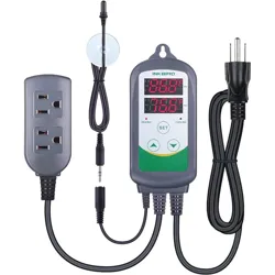
Plug and play design, easy to use;
Dual relay output, be able to connect with refrigeration
and heating equipment at the same time;
Support reading with Centigrade or Fahrenheit unit;
Maximum output load: 1200W(110V) / 2200W(220V);
Dual display window, be able to display measured
temperature and set temperature at the same time;
Temperature calibration;
Compressor delay protection for refrigeration control;
High and low temperature alarms are available;
Over-temperature and sensor fault alarm;
Heating/cooling dif
ferential function could be set
separately for refrigeration and heating to protect
temperature controller from violent change.
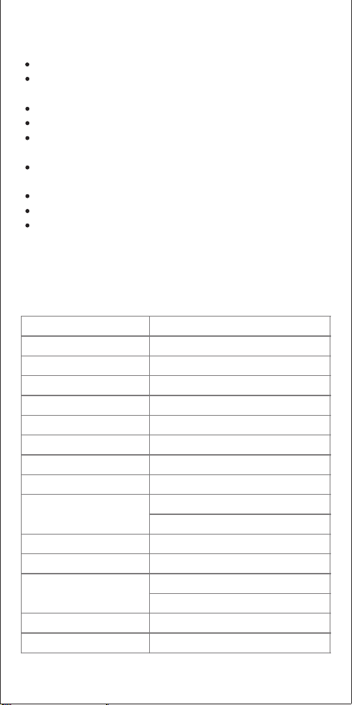
3.Specification
Temperature Control Range
-50~120 °C / -58~248 ° F
Temperature Resolution
0.1 ° C / 0.1° F
Temperature Accuracy
±1°C (-50 ~ 70°C) / ±1°F (-58 ~ 160° F)
Temperature Control Mode
On/Off Control, Heating and Cooling
Input Power
100 ~240VAC, 50Hz/60Hz
Temperature Control Output
Max. 10A, 100V ~240V AC
Buzzer Alarm
High and Low Temperature Alarm
Sensor Type
NTC sensor (Including)
Sensor Length
2m / 6.56ft
Cooling (10A, 100-240VAC)
Heating (10A, 100-240VAC)
Input Power Cable Length
1.5m ( 5ft )
Dimension (Main Body)
140x68x33mm (5.5x2.7x1.3 inc
h)
Ambient Temperature
-30~ 75 ° C / -22~ 167 ° F
Temperature: -20~ 60 ° C / -4~ 140 ° F
Humidity: 20~85% (No Condensate )
1 Year
Warranty
Storage
Relay Contact Capacity
2
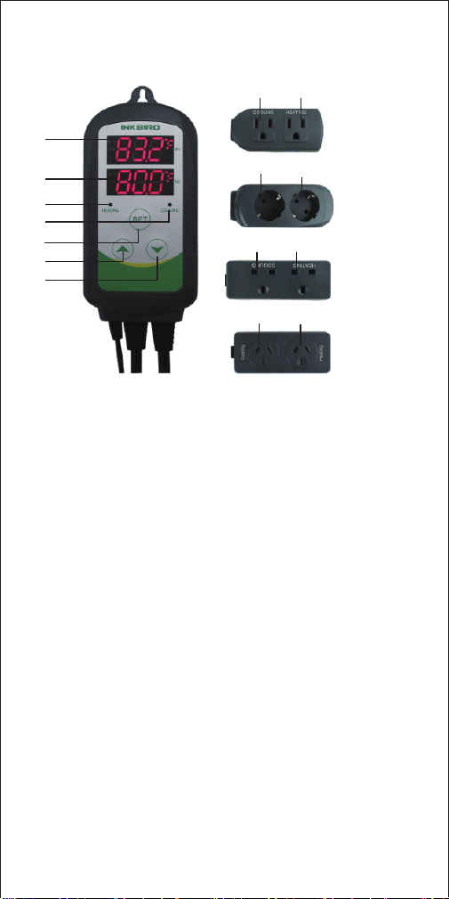
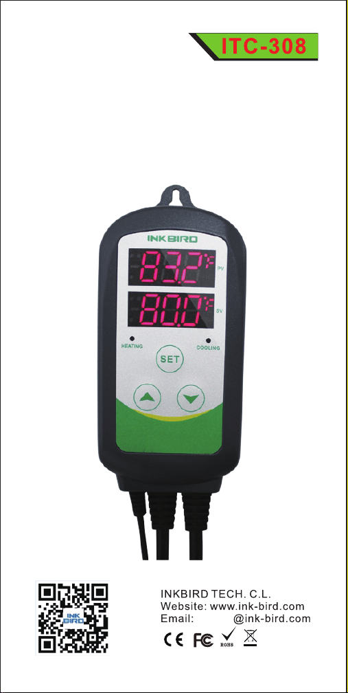
4.Keys Instruction
① PV: Process Value. under running mode, display current
temperature; under setting mode, display menu code.
② SV: Setting Value. under running mode, display setting
temperature; under setting mode, display setting value.
③ Heating Indicator Lamp: when the light is on, start
heating.
④ Cooling indicator Lamp: when the light is on, start
refrigeration; when the light is flickering, the compressor is
under delay protection.
⑤ SET key: press SET key for 3 seconds to enter menu for
function setting. During the setting process, pre
ss SET key
for 3 seconds to quit and save setting changes.
⑥ INCREASE key: under running mode, press INCREASE
key to inquiry HD value; under setting mode, press
INCREASE key to increase value.
⑦ DECRESE key: under running mode, press DECRESE
key to inquiry CD value; under setting mode, press
DECRESE key to decrease value.
⑧ Heating Device Socket: this socket is for heating output.
⑨ Cooling Device Socket: the socket is for refrigeration
output.
3
⑦
①
②
③
④
⑥
⑤
⑧⑨
⑧
⑧
⑧
⑨
⑨
⑨
US Sockets
EU Sockets
UK Sockets
AU Sockets
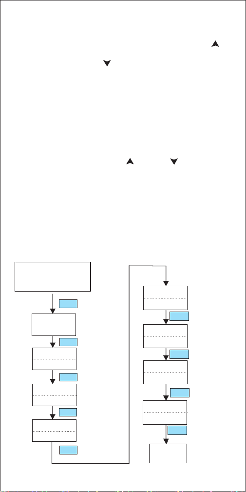
5. Key Operation Instruction
5.3 Setup Flow Chart
When the controller is working normally, short press “ ”
key for one time, then the heating differential ( HD) will be
displayed; short press “ ” for one time, then the cooling
differential (CD) will be displayed. The screen will return to
normal display mode after 2 seconds.
5.2 How to Set Parameters
When the controller is working normally, press “SET” key
for over 3 seconds to enter parameters set up mode. “SET”
indicator lamp will on. PV window displays the first menu
code “TS”, while SV window displays according setting
value. Press “ SET ” key to go to next menu and display
accordin
g menu code, press “ ” key or “ ”key to set
current parameter value.
After setting done, press “SET” key for 3 seconds at any
time to save the parameters change and return to normal
temperature display mode. During setting, if there is no
operation for 10 seconds, the system will quit setting
mode and return to normal temperature display mode
without saving the parameters change.
4
Press “SET” key for over
3 seconds to enter
paramerers set up mode.
3S
AL
99 °C
PT
-40 °C
TS
HD
CD
AH
Temperature
Set Value
Heating
Differential
Value
Temperature
Calibration
Compressor
Delay
25°C
2.0°C
2.0°C
3 minute
CA
Temperature
Unit
Cooling
Differential
Value
Alarm High
Limit
SET
Working
Normally
0 °C
CF
C
3S
SET
SET
SET
SET
SET
SET
SET
SET
Alarm Low
Limit
5
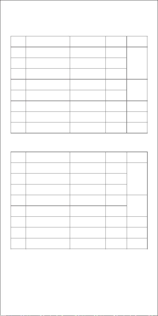
6. Menu Instruction
When the temperature is displayed in Centigrade
When the temperature is displayed in Fahrenheit
6.1 Temperature Control Range Setting (TS, HD, CD)
When the controller is working normally, the LED displays
current measured temperature, and automatically identify
and switch refrigeration and heating working modes.
TS
HD
CD
AH
AL
PT
CA
CF
Display in Fahrenheit
or Centigrade
Temperature
Calibration
Compressor Delay
Alarm Low Limit
Alarm High Limit
Cooling Differential
Value
Heating Differential
Value
Temperature Set
Value
6.1
6.2
6.3
6.4
6.5
-50~120°C
25°C
0.3~15°C
0.3~15°C
2.0°C
2.0°C
-50~120°C
-50~120°C
90°C
-40°C
0~10 minutes
0
-15°C~15°C
C
0°C
Menu
code
Function
Setting range
Default
setting
Remarks
TS
HD
CD
AH
AL
PT
CA
CF
Display in Fahrenheit
or Centigrade
Temperature
Calibration
Compressor Delay
Alarm Low Limit
Alarm High Limit
Cooling Differential
Value
Heating Differential
Value
Temperature Set
Value
6.1
6.2
6.3
6.4
6.5
-50~248°F
77°F
1~30°F
1~30°F
3°F
3°F
-50~248°F
-50~248°F
200°F
-40°F
0~10 minutes
0
-15°F~15°F
F
0°F
Menu
code
Function
Setting range
Default
setting
Remarks

6
When the measured temperature PV≤TS (temperature
set value), the cool indicator lamp will off, and the
refrigeration relay stops working.
6.2 Alarm High/Low Limit Setting (AH, AL)
When measured temperature is higher or equal to AH, high
temperature alarm will be triggered, buzzer will alarm with
tone “bi-bi-Biii” until the temperature is lower than AH or
any key is pressed.
When measured temperature is lower or equal to AL, low
temperature alarm will be triggered, buzzer will alarm with
tone “bi-bi-Biii” until the temperature >AL or any key is
press
ed.
6.3 Compressor Delay (PT)
Under refrigeration mode, after power on, if the measured
temperature is higher than the value of setting temperature
(TS) plus cooling differential(CD), the equipment won't start
refrigeration immediately, but waiting for a delay time.
When the measured temperature PV ≥ TS(temperature
set value) + CD (cooling differential value), system
enters refrigeration status, the cool indicator lamp will on,
and refrigeration relay starts to work; when the cool
indicator lamp is flickering, it means the refrigerat
ion
equipment is under compressor delay protection status.
In case the time interval between two refrigeration is less
than PT, please refer to 6.3.
For example, set TS=25°C, CD=2°C , and HD=3°C, then
when measured temperature is higher or equal to 27°C
(TS+CD), system enters refrigeration status; when
temperature decline to 25°C(TS), stop refrigeration; when
measured temperature is lower or equal to 22°C(TS-HD),
system enters heating status; when the temperature raised
to 25°C(TS), stop heating.
When the measured temperature PV≤TS (temper
ature set
value)-HD (heating differential value), system enter
heating status, the heat indicator lamp will on, and heating
relay starts to work; when the measured temperature PV≥
TS(temperature setting), the heat indicator lamp will of,
and heating relay stops working.

7
6.4 Temperature Calibration (CA)
When there is deviation between measured temperature and
actual temperature, use temperature calibration function to
align the measured temperature and actual temperature.
The corrected temperature is equal to temperature before
calibration plus corrected value(corrected value could be
positive value, 0 or negative value).
6.5 Display in Fahrenheit or Centigrade unit (CF)
Users can select display with Fahrenheit or Centigrade
temperature value according to their own habit. Default
setting is displ
ay with Centigrade temperature value. For
displaying with Fahrenheit temperature value, set CF value
as F.
Attentions: when CF value changed, all the setting value
will be recovered to factory settings.
7. Error Description
Sensor Fault Alarm:
when temperature sensor is in short circuit or open loop, the
controller will initiate sensor fault mode, and cancel all the
actions. The buzzer will alarm, LED displays ER. Buzzer
alarm could be dismissed by pressing any key. After faults
solved, the system will return to normal working mode.
Over-temperature A
larm:
when measured temperature exceeds the measuring range
(less than -50°C /-58° F or higher than 99 °C/210 ° F), the
controller will initiate over-temperature alarm mode, and
cancel all the actions. The buzzer will alarm, LED displays
HL. Buzzer alarm could be dismissed by pressing any key.
When temperature returns to measuring range, the system
will return to normal working status.
When the time interval between two refrigeration operation
is larger than preset delay, the equipment will start
refrigeration immediately; when the time interval between
two refrigeration is less than preset delay, the equipment
won't start refrigeration until preset delay is satisfied.
Delay time will be calculated right after the moment
refrigeration stops.