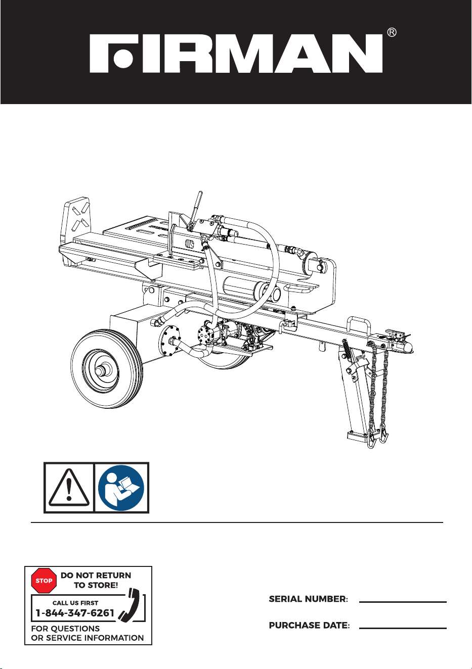
OPERATOR’S MANUAL
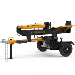
28 TON GASOLINE LOG SPLITTER
Record product information to reference when ordering parts or
obtaining warranty coverage.
GS2801
1
Table of Contents
Introduction . . . . . . . . . . . . . . . . . . . . . . . . . . . . . . . . . . . . . . . . . . . . . . . . . . . . . . . . . . . . . . . . . . . . .1
Features Controls and on Product Hazard Labels. . . . . . . . . . . . . . . . . . . . . . . . . . . . . . . . . . 6
Assembly . . . . . . . . . . . . . . . . . . . . . . . . . . . . . . . . . . . . . . . . . . . . . . . . . . . . . . . . . . . . . . . . . . . . . . 11
Operation . . . . . . . . . . . . . . . . . . . . . . . . . . . . . . . . . . . . . . . . . . . . . . . . . . . . . . . . . . . . . . . . . . . . . . 19
Maintenance - Storage. . . . . . . . . . . . . . . . . . . . . . . . . . . . . . . . . . . . . . . . . . . . . . . . . . . . . . . . . . 29
Troubleshooting- Specifications . . . . . . . . . . . . . . . . . . . . . . . . . . . . . . . . . . . . . . . . . . . . . . . . 36
Parts Diagrams - Parts Lists . . . . . . . . . . . . . . . . . . . . . . . . . . . . . . . . . . . . . . . . . . . . . . . . . . . . 3 8
Service - Warranty. . . . . . . . . . . . . . . . . . . . . . . . . . . . . . . . . . . . . . . . . . . . . . . . . . . . . . . . . . . . . . 43
REGISTER YOUR PRODUCT
Register your product using the QR code provided or at
www.firmanpowerequipment.com .
INTRODUCTION
Thank you for purchasing a FIRMAN log splitter. You have selected a high-quality, precision engineered
log splitter designed and tested to give you years of satisfactory service.
This manual contains safety information to make you aware of the hazards and risks associated
with log splitter products and how to avoid them. It is important that you read and understand
these instructions thoroughly before attempting to start or operate log splitter. Save these
original instructions for future reference.
All information in this publication is based on the latest production information available at the
time of approval for printing. The manufacturer reserves the right to change, alter or otherwise
improve the log splitter and this documentation at any time without prior notice.
INTRODUCTION

2
SIGNAL WORDS
DANGERWARNINGCAUTION
Indicates a hazard
which, if not avoided,
will result in death or
serious injury.
Indicates a hazard
which, if not avoided,
could result in death
or serious injury.
Indicates a hazard
which, if not avoided,
could result in minor or
moderate injury.
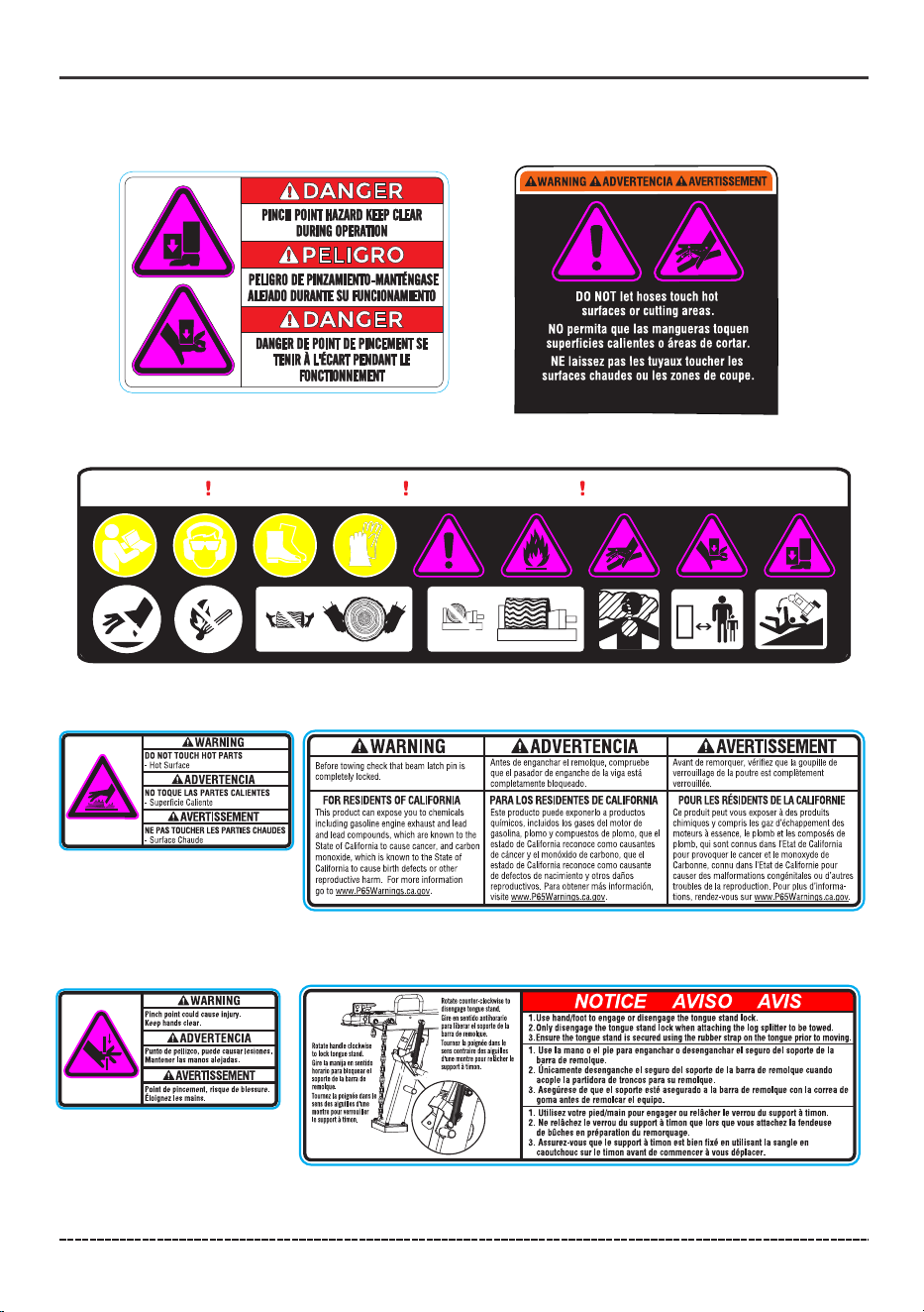
Fire- Fuel and its vapors are extremely flammable which could
cause burns or fire resulting in death or serious injury.Engine
exhaust could cause fire resulting in death or serious injury.
Hot Surface- Muffler could cause burns resulting in serious injury.
Water contact with a power source could cause electrical shock
resulting in death or serious injury.
Safety Alert Symbol - Indicates a potential personal injury hazard.
Operator's Manual- Failure to follow warnings, instructions and
operator's manual could result in death or serious injury.
English Customer Service: 1-844-FIRMAN1
NOTICE
Indicates information
considered Important,
but not hazard-related.
INTRODUCTION
Eye and Ear Protection - Always wear safety goggles or safety
glasses with side shields, and as necessary a full face-shield as well
as full ear protection when operating this product.
Footwear - Always wear safety shoes or heavy boots when
operating the machine.
Gloves - Always wear nonslip, heavy-duty protective gloves when operating
this product.
Skin Injection Hazard - High pressure hydraulic oil can inject under your skin.
Make sure all fittings are tightly secure before applying pressure. Relieve
system pressure before servicing.
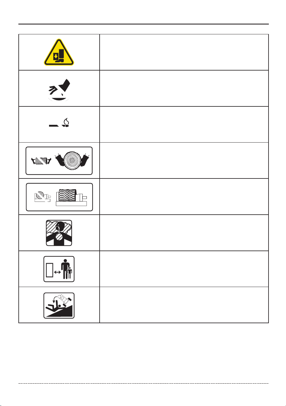
Always keep hands away from the wedge and the hydraulic cylinder.
Moving parts can crush or cut.
3
English Customer Service: 1-844-FIRMAN1
INTRODUCTION
Always keep feet away from the wedge slide and the hydraulic
cylinder. Moving parts can crush or cut.
Hot Surface- Muffler could cause burns resulting in serious
injury.
Open Flame alert - Fuel and its vapors are extremely flammable
and explosive. Keep fuel away from smoking, open flames,
sparks, pilot lights, heat, and other ignition sources.
Hold logs on sides when loading. Keep hands and feet away
from cylinder, wedge, and partially split logs.
Never place hands or any part of the body between a log and
any part of the log splitter.Do not split logs against the grain.
Split logs end to end in the direction of the grain only.
Toxic Fumes- Engine exhaust contains carbon monoxide,
a poisonous gas that will kill you in minutes. You cannot
smell it or see it.
Clearance - Keep all objects including others at least 10 feet
(3m) from this machine. Only one person should operate the
log splitter and load the logs.
Never operate on an incline. Make sure the log splitter is on a level
surface. Block tires and ensure support leg is secure to prevent
unintended movement of the log splitter during operation.

4
English Customer Service: 1-844-FIRMAN1
WARNING! This product can expose you to chemicals including gasoline engine
exhaust and lead and lead compounds, which are known to the state of California to
cause cancer, and carbon monoxide, which is known to the State of California to
cause birth defects or other reproductive harm. For more information go to
www.P65Warning.ca.gov.
INTRODUCTION
Training
1. Read the Operator’s Manual completely before attempting to use this log splitter.
2. Do not allow anyone to operate your log splitter who has not read the Operator’s Manual or has
not been instructed on the safe use of the log splitter.
3. Never allow children or untrained adults to operate this machine.
4. Many accidents occur when more than one (1) person operates the log splitter. If a helper is
assisting in loading logs to be split, never actuate controls until helper is clear of the area.
5. Never allow anyone to ride on the machine.
6. Never transport cargo on the log splitter.
7. High fluid pressures are developed in hydraulic log splitters. Pressurized hydraulic fluid
escaping through a pin hole opening can puncture skin and cause sever blood poisoning.
Therefore, the following instructions should be heeded at all times.
7a. Do not operate the unit with frayed, kinked, cracked or damaged hoses, fittings, or tubing.
7b. Stop the engine and relieve hydraulic system pressure before changing or adjusting fittings,
hoses, tubing, or other system components.
7c. Do not adjust the pressure settings of the pump or valve.
7d. Do not check for leaks with your hand. Leaks can be detected by passing cardboard or wood
over the suspected area. Look for discoloration. If injured by escaping fluid, see a doctor at once.
Serious infection or reaction can develop if proper medical treatment is not administered
immediately.
8. Keep the operator zone and adjacent area clear for safe, secure footing.
9. The log splitter is equipped with a spark arrestor for use near unimproved forest, brush, or grass
covered land. Make sure you comply with local, state, and federal codes. Take appropriate
fire-fighting equipment with you.
10. Log splitters should be used only for splitting wood. Do not use for other purposes unless the
manufacturer provides attachments and instructions.
11. Only split wood with the grain. NEVER split perpendicular to the grain.
12. Keep the area of operation clear of all persons, particularly small children.
Preparation
1. Be thoroughly familiar with all controls and with proper use of the equipment.
2. Safety Gear:
2a. Always wear safety shoes or heavy boots when operating the machine.
2b. Always wear safety goggles or safety glasses with side shields, and as necessary a full
face-shield when operating or servicing the machine.
2c. Never wear jewelry or loose-fitting clothing that might become entangled in moving or
rotating parts of the machine.
2d. Always wear full ear protection when operating the machine.
3. Make sure the log splitter is on a level surface. Block tires and ensure support leg is secure to
prevent unintended movement of the log splitter during operation.
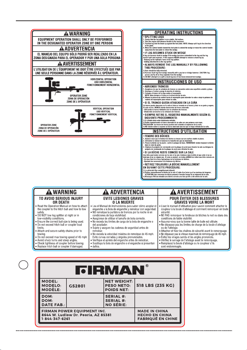
3a. Always operate the log splitter from the manufacturer’s indicated operator zone.
4. Logs should be cut as squarely as possible.

5
5. Fuel:
5a. Use an approved fuel container.
5b. Never add fuel to a running or hot engine.
5c. Fill fuel tank outdoors with extreme care. Never fill fuel tank indoors.
5d. Replace gasoline cap securely and clean up any spilled fuel. If fuel is spilled on clothing, change
clothing immediately.
5e. Never fill fuel containers inside a vehicle or on a truck or trailer bed with a plastic liner. Always
place container on the ground away from your vehicle before filling.
5f. Keep the fuel nozzle in contact with the rim of the fuel tank or container opening at all times
until fueling is complete. Do not use a nozzle lock open device.
English Customer Service: 1-844-FIRMAN1
INTRODUCTION
Operation
1. Be sure to confirm all hose connections and hose clamps are tight before each use. It is possible
for connections to vibrate loose over time.
2. Never leave the machine unattended with the engine operating.
3. Never operate the machine when under the influence of alcohol, drugs or medication.
4. The machine owner shall instruct all operators to read and understand the operators manual to
ensure safe log splitter operation.
5. Always operate the log splitter with all safety equipment in place and all controls properly
adjusted for safe operation.
6. Always operate the log splitter at manufacturer’s recommended speed.
7. Always keep hands and feet clear of moving parts and partially split logs during the splitting
operation.
8. When loading a ram-type log splitter, place your hands on the sides of the log, not the ends.
Never place your hands or any part of your body between a log and any part of the log splitter.
9. On ram-type log splitters, never attempt to split more than one (1) log at a time unless the ram
has been fully extended and a second log is needed to complete the separation of the first log.
10. On ram-type log splitters on which the logs are not cut square, the longest portion of the log
should be rotated down and the most square end placed against the foot plate.
11. Only split logs with the grain of the wood.
12. Use only your hand to operate the log splitter controls.
13. Do not refuel until the engine has been turned off and cooled for at least 2 minutes.
Maintenance and Storage
1. Always shut off the engine while repairing or adjusting the log splitter except as recommended
by the manufacturer.
2. Clean debris and chaff from the engine cylinder, cylinder head fins, recoil starter cover, and muffler
areas. Clean engine muffler spark arrestor and inspect it regularly (follow manufacturer’s service
instructions). Replace, if damaged.
3. Never store the unit indoors with fuel in the tank. Fumes might reach an open flame spark. Allow
the engine to cool before storing in any enclosure.
4. Clear debris from movable parts, but only when the engine is shut off.
5. Check to be sure all nuts and bolts are tight to ensure the equipment is in safe working condition.
WARNING! Before starting and using this log splitter, read and follow all the on product labels and
safety information contained in the Operator's manual. Failure to follow all on product labels and
Operator's manual could result in death or serious injury to the operator or bystanders.
6
English Customer Service: 1-844-FIRMAN1
*We are always working to improve our products. Therefore, the enclosed product
may differ slightly from the image on this page.
FEATURES, CONTROLS AND ON -PRODUCT HAZARD LABELS
⑯
⑮
⑭
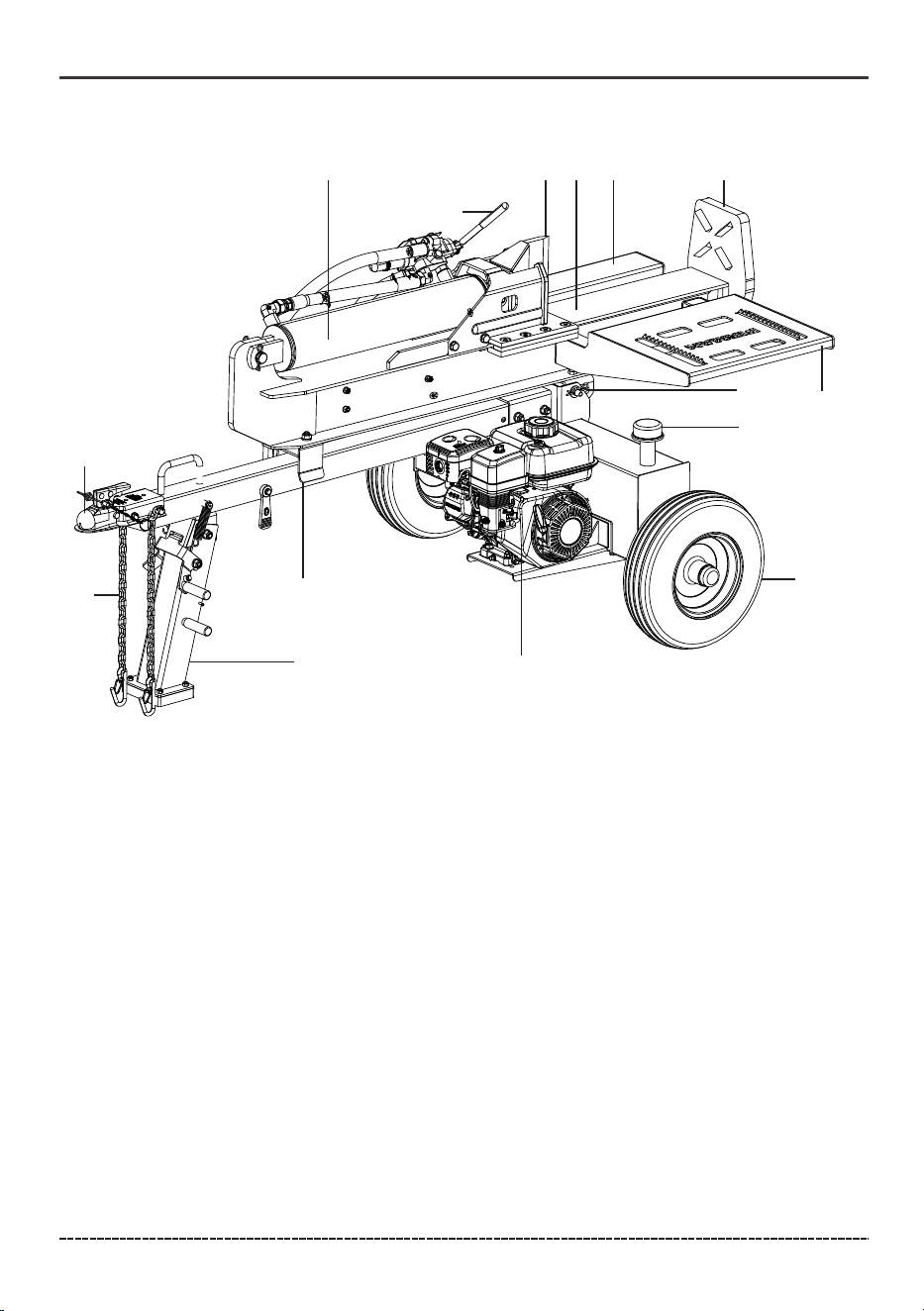
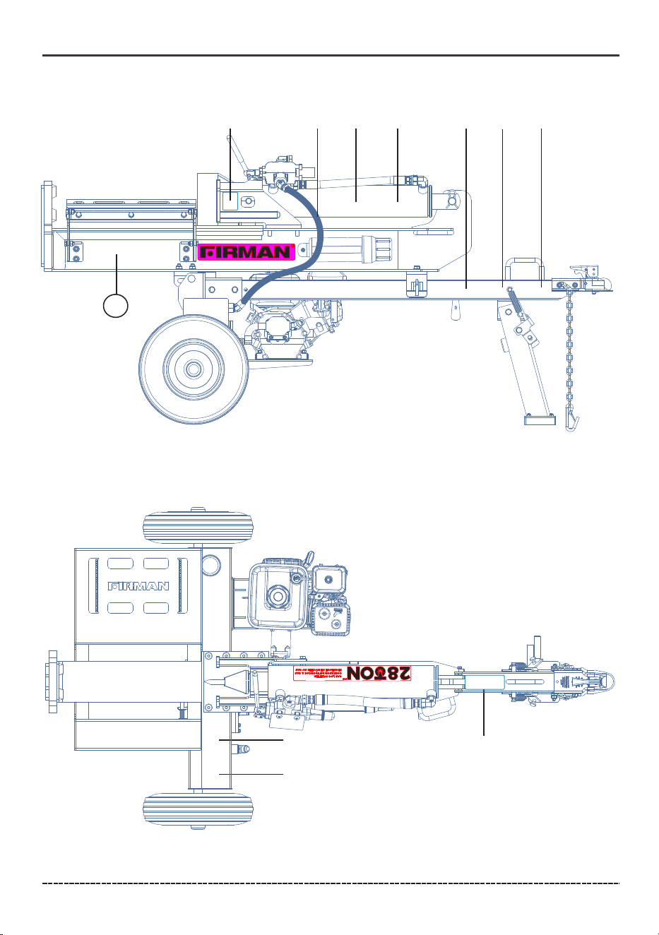
Log Splitter
1. 2 in. (5.1 cm) Ball Coupler
2. Foot Plate
3. Hydraulic Cylinder
4. Control Valve Handle
5. Wedge
6. Beam
7. Log Cradle
8. Tires
9. 208cc FIRMAN Engine
10. Vent Cap
11. Beam Pivot
12. Beam Lock Assembly
13. Tongue Stand
14. Safety Chains with Hooks
15. Log Table
Splitting control The machine shall have an operator-presence control (OPC) for its splitting function.
For controls that move in the same direction as the ram or wedge, they shall move forward on
horizontal machines and down wardon vertical machines for the splitting action. Hand-operated
splitting controls (excludes power source controls) shall provide a minimum of 70 mm (2.75 in) of
clearance in all directions from the control and through out the operating range. The control’s
function and direction shall be identified by a durable label.
1
2
1. 2 in. (5.1 cm) Ball Coupler – For towing the log splitter behind your vehicle.
2. Foot Plate
3. Hydraulic Cylinder – Converts hydraulic pressure into linear force.
4. Control Valve Handle – Controls the movement of the wedge slide.
5. Wedge
6. Beam
7. Log Cradle
8. Tires – Maximum travel speed is 45 MPH (72 KM/H).
9. 208cc FIRMAN Engine
10. Fill Cap
11. Beam Pivot
12. Beam Lock Assembly
13. Tongue Stand – Supports log splitter while operating. Raise leg for towing.
14. Safety Chains with Hooks – For use while towing.
3
4
5
6
7
10
11
8
9
12
13
14
15
7
English Customer Service: 1-844-FIRMAN1
1
2
5
6
7
8
9
10
11
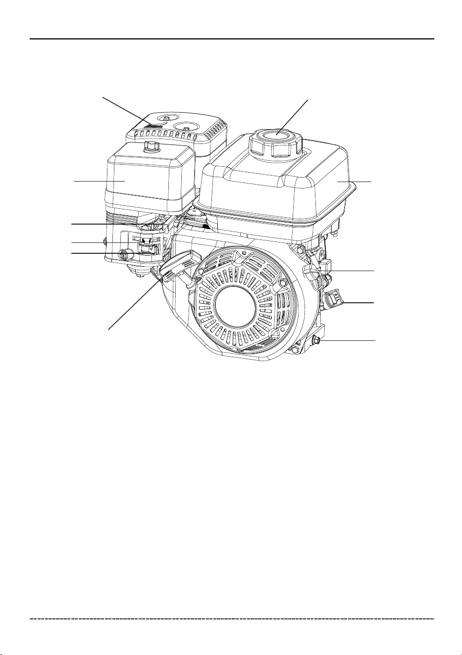
1. Fuel Cap
2. 0.9 Gal (3.2L) Fuel Tank
3. Engine Switch
4. Oil Fill Cap/Dipstick
5. Oil Drain Bolt
6. Recoil Starter
7. Fuel Valve
8. Choke Lever
9. Throttle
10. Air Filter
11. Muffler
3
4
FEATURES, CONTROLS AND ON -PRODUCT HAZARD LABELS
1. Fuel Cap
2. 0.9 Gal (3.2L) Fuel Tank
3. Engine Switch
4. Oil Fill Cap/Dipstick – Used to check and fill oil level.
5. Oil Drain Bolt – Used to drain engine oil.
6. Recoil Starter – Used to manually start the engine.
7. Fuel Valve
8. Choke Lever - Used for cold engine starting.
9. Throttle – Used to control the engine speed.
10. Air Filter
11. Muffler
8
English Customer Service: 1-844-FIRMAN1
FEATURES, CONTROLS AND ON -PRODUCT HAZARD LABELS
①②
③
④
⑨
⑤
⑦
⑥
⑧
⑩
11
9
English Customer Service: 1-844-FIRMAN1
FEATURES, CONTROLS AND ON -PRODUCT HAZARD LABELS
①
②
③
④
⑤
⑦
⑥
10
English Customer Service: 1-844-FIRMAN1
FEATURES, CONTROLS AND ON -PRODUCT HAZARD LABELS
⑧
⑨
11
⑩
11
English Customer Service: 1-844-FIRMAN1
ASSEMBLY
Your log splitter requires some assembly. If you have any questions regarding the assembly of
your log splitter, call our help line at 1-844-347-6261. Please have your serial number and model
number available.
ASSEMBLY
STEP 1: Unpack Unit
Tools
1.1 Set the shipping crate on a solid, flat surface.
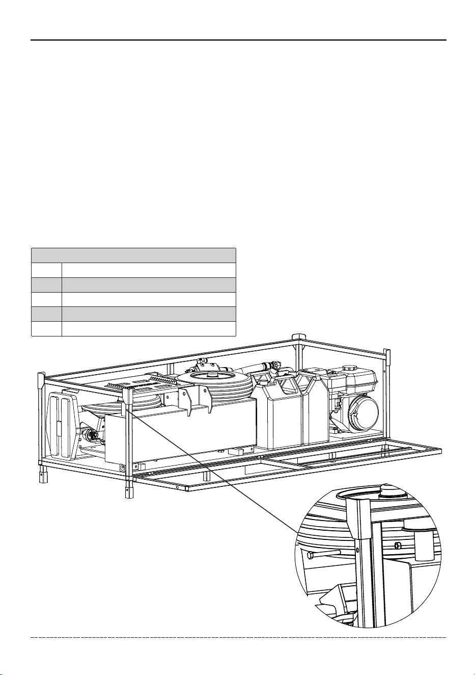
1.2 Carefully cut the shipping bands and remove the bolted side of the shipping crate.
1.3 Locate all hardware and components on GS2801 Parts Diagram and Parts List before beginning
assembly.
• Flat Screw Driver
• Hammer or Crowbar
• Band Cutter
• 8mm, 10mm, 13mm,14mm, 17mm,18mm, 19mm, 27mm and 32mm Wrenches
• Torque Wrench
Band Cutter
10mm wrenches and/or socket ratchet
13mm wrenches and/or socket ratchet
17mm wrenches and/or socket ratchet
1
2
3
4
Tool
Ref. #
Description
12
Step 2: Install the Wheels
2.1
2.2
2.3
2.4
English Customer Service: 1-844-FIRMAN1
ASSEMBLY
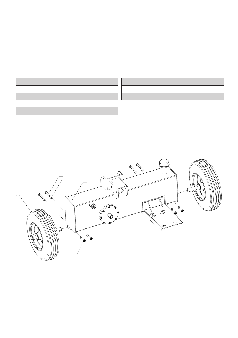
Remove the oil tank (31) and wheel assembly (98) from the steel pallet and place them on a
horizontal surface.
Install the wheel axle of the wheel into the bushing at the bottom of the oil tank, aligning it
with the mounting holes.
Secure the wheel with the M10*55 bolts(36) (Torque to 35.4 lbf-ft (48 N·m)), flat washers Ø10
(37), and M10 nylock nuts (38).
Complete the installation of the wheel on the other side by following the above operations.
Tool
Ref. #
Description
2*17mm wrenches and/or socket ratchet
1
98
36
37
31
38
Parts List
Ref. #
Description
Part #
Bolt M10*55
Washer Ø10
Lock Nut M10
36
37
38
710718008
710717003
710717075
QTY.
4
8
4
13
Step 3: Install The Tongue
English Customer Service: 1-844-FIRMAN1
ASSEMBLY
3.1
31
33
6
2
99
Parts List
Ref. #
Description
Part #
Bolt M12 * 110
Washer Ø12
Lock Nut M12
33
2
6
710717133
710717007
710717008
Tools
Ref. #
Description
18mm wrenches and/or socket ratchet
1
2
19mm wrenches and/or socket ratchet
QTY.
2
4
2
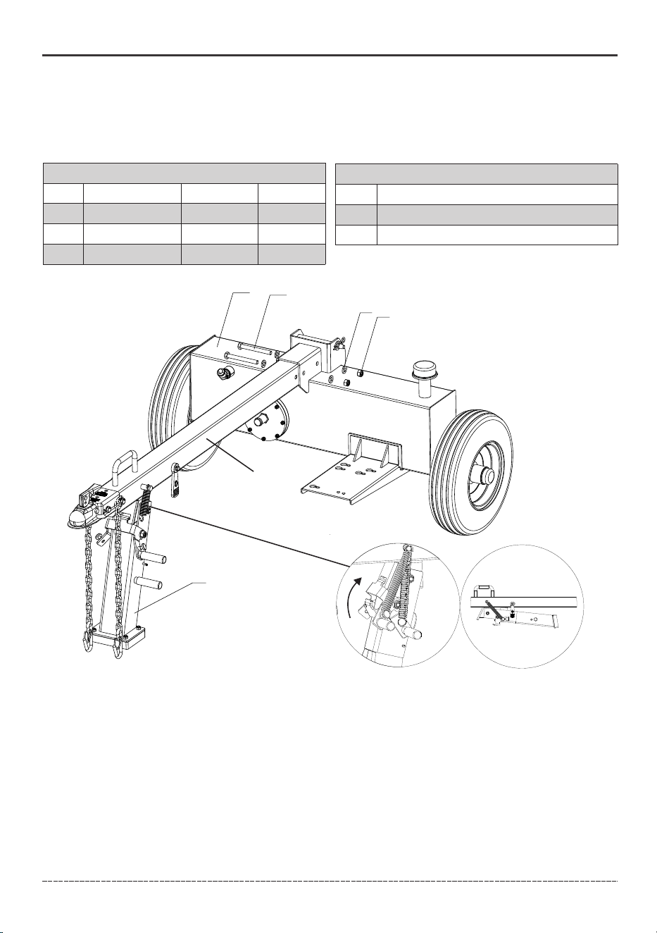
Rotate the tongue stand clockwise as far as it will go using the fixed handle on the stand.
Rotate the stand lock attached to the tongue stand clockwise. Verify that the tongue stand is
locked and will not inadvertently rotate.
3.2
3.3
To lock the tongue stand
Use your foot or hand to rotate the tongue stand lock counter clockwise.
Lift the tongue from the handle to unweight the tongue stand.
Gentle push the tongue stand allowing the springs to pull the stand under the tongue stopping
with the rubber bumper.
Attach the rubber strap from the tongue main tube to the hook on the stand to prevent unwanted
movement and bouncing during towing.
To unlock the tongue stand
3.4
3.5
100
Rotate the tongue stand (99) down and lock into the extended position following the steps
listed below. Secure the tongue assembly(100) to the hydraulic tank (31) using M12*110
screws (33)(Torque to 61.2 lbf-ft (83 N·m)), M12 flat washers (2) and M12 nylock nuts (6).
14
English Customer Service: 1-844-FIRMAN1
ASSEMBLY
Step 4: Install The Engine
Tools
Ref. #
Description
13mm wrenches and/or socket ratchet
1
71
73
64
72
37
23
Parts List
Ref. #
Description
Part #
Bolt M8 * 40
Washer Ø8
Lock Nut M8
Washer Ø10
72
64
23
37
710718006
710717045
710717044
710717003
QTY.
4
1
1
1
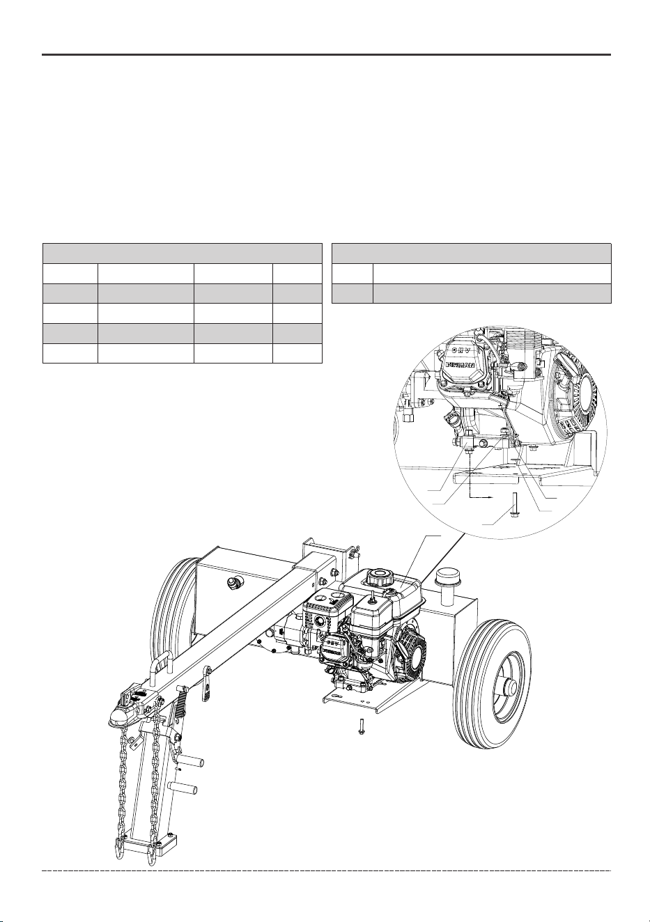
Remove the Engine (71) from the wooden board by removing the red color bracket and red
colored bolt.
Set the engine on the platform, dropping the bolt heads through the tear drop hole.
Slide the engine to align the 4th hole.
At this point the user can place a single washer under the engine to ensure equal pressure on
the base of the engine.
Tighten all the hardware.
4.1
4.2
4.3
4.4
4.5
15
English Customer Service: 1-844-FIRMAN1
ASSEMBLY
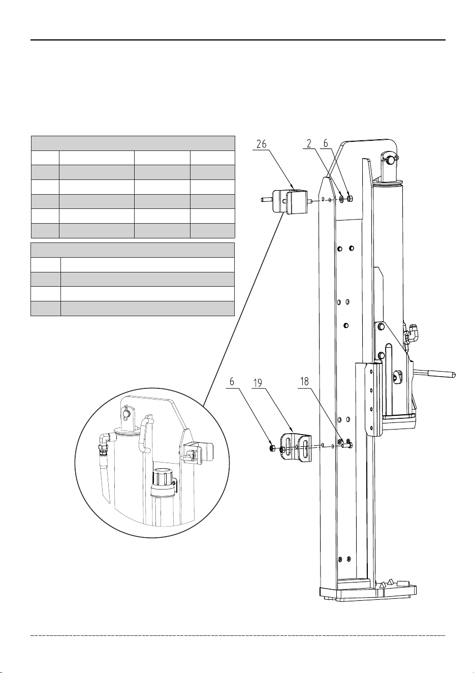
Step 5: Install Beam Pivot/Beam Lock
Parts List
Ref. #
Description
Part #
Washer Ø12
Lock Nut M12
Bolt M12*30
Beam Pivot
Assy, Beam Lock
2
6
18
19
26
710717007
710717008
710718002
710718252
710418026
Tools
Ref. #
Description
18mm wrench and/or socket ratchet
1
2
3
19mm wrench and/or socket ratchet
Hammer or crowbar
QTY.
2
4
2
1
1
NOTICE When fully assembled, the pull pin of the
beam lock must be positioned on the same side
as the slot in the tongue.
Remove the beam from the pallet by removing two red colored bolts. This step requires
multiple people to ensure safety and avoid injury. Use a hammer or crowbar to remove the
wooden block attached to the base of the pallet so that the beam can be slid out.
5.1
NOTICE Stand the beam up vertically using 2 or more people.
5.2
Stand the beam upright.
16
English Customer Service: 1-844-FIRMAN1
ASSEMBLY
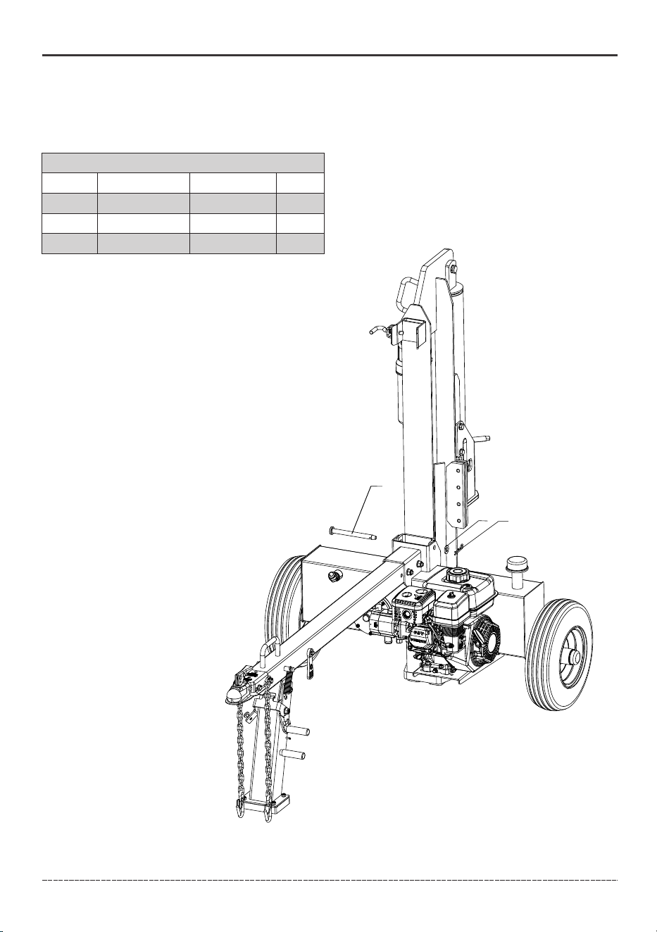
Step 6: Install the Beam
WARNING! The beam is extremely heavy and shall only be handled with 2 or more people.
To avoid muscle strain or back injury DO NOT try and lift or handle the beam without assistance.
Roll the tank into position so the pivot holes of the tank and beam are aligned.
Insert the beam pin (32) and secure with Ø16 washer (34) and R-pin (25).
6.1
6.2
32
34
25
Parts List
Ref. #
Description
Part #
Beam Pin
Washer Ø16
R-Pin
32
34
25
710718317
710718032
710717113
1
1
1
QTY.
17
English Customer Service: 1-844-FIRMAN1
ASSEMBLY
NOTICE The Pump-Valve Hydraulic Hose(High Pressure) and Valve-Tank Hydraulic Hose(Low
Pressure) may be preassembled by the factory, check your hoses per below instructions to
ensure proper assembly.
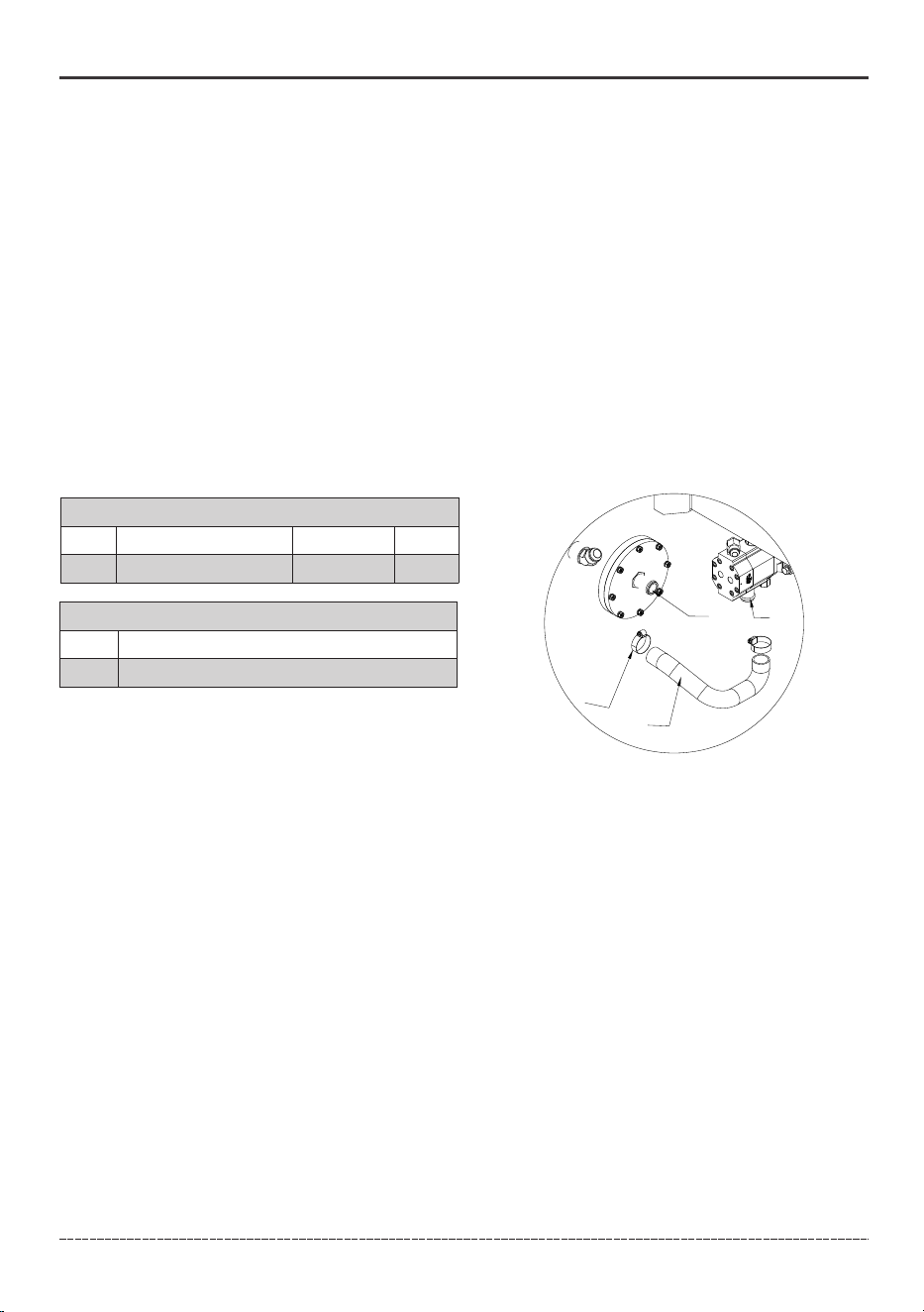
Step 7: Install the Hoses
Using the provided hose clamps, connect one end of the clear suction hose (46) to the suction
fitting port (A) and the other end to the pump inlet (B).Securely tighten the clamps on both ends
of the suction hose with either a flat head screw driver or 8mm socket. Torque to 2.9 lbf-ft -
4.4 lbf-ft (4-6 N.m).
Oil Inlet Hose
NOTICE After running the log splitter and the fluid has heated up the user should verify that the
hose clamps are secure and remain tight.
7.1
Parts List
Ref. #
Description
Part #
Worm Gear Hose Clamp
45
710718033
46
45
A
B
Tool
Ref. #
Description
Flat Head Screw Driver or 8mm socket
1
QTY.
2
NOTICE Red shipping plugs must be removed from hydraulic pump prior to installing hoses.
The operating handle of the hydraulic valve may be tied during transportation, and the straps need
to be removed before installing the handle with the clevis pin.
18
English Customer Service: 1-844-FIRMAN1
ASSEMBLY
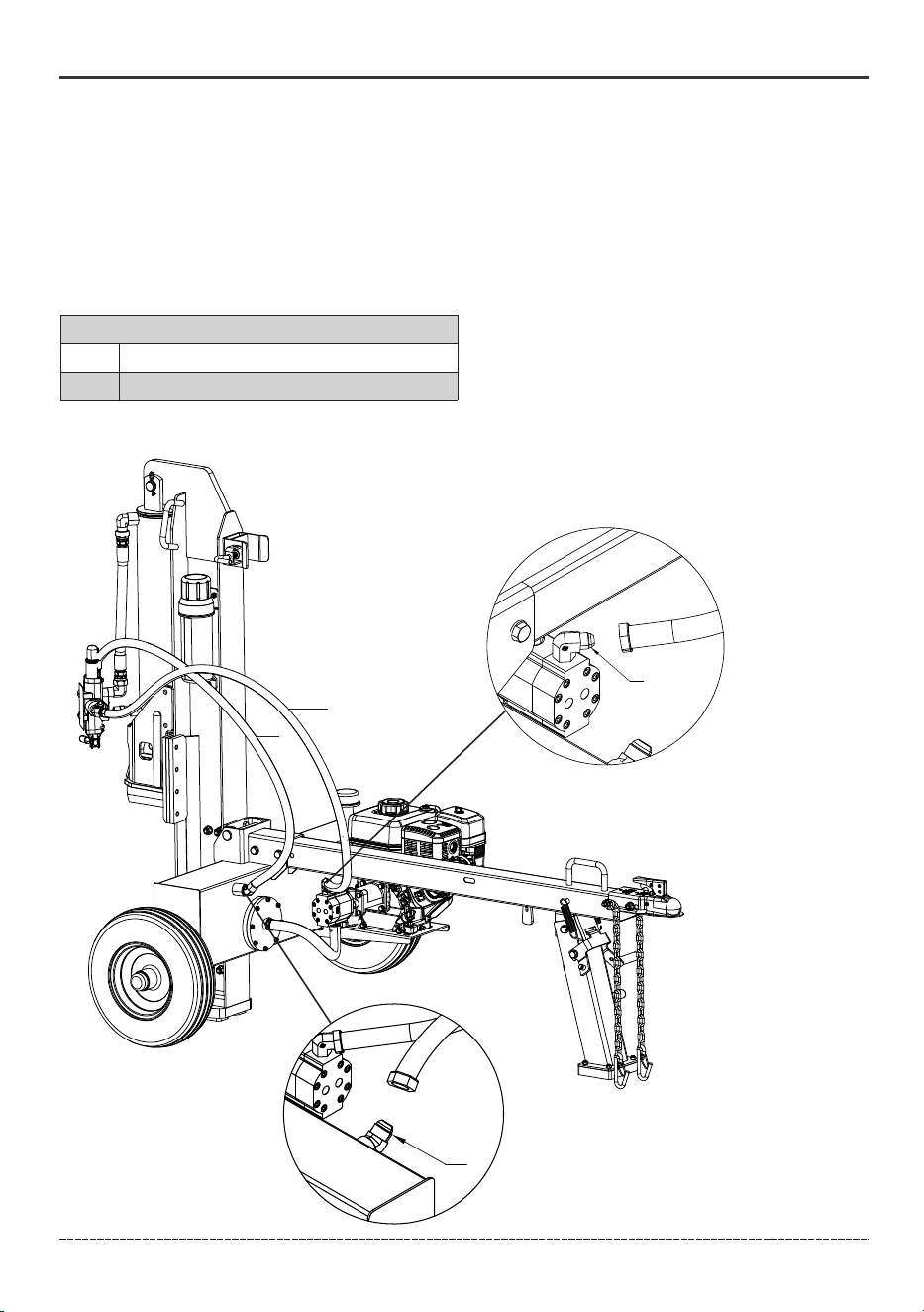
Connect the loose end of the pump-valve hydraulic hose (C) to the pump outlet (D). Securely
tighten the high pressure hydraulic hose with a 27mm wrench. Tighten to 44 lbf-ft – 52 lbf-ft
(60-71 N.m).
Hydraulic Hose (Pump-Valve)
D
7.2
F
Tool
Ref. #
Description
1
C
E
NOTICE
Assemble the hoses with the log splitter beam
in the vertical position as shown in the diagram
below.
After tightening, ensure the hoses are not twisted
or kinked.
27mm,32mm wrench
Hydraulic Hose (Valve-Tank)
7.3
Connect the loose end of the valve-tank hydraulic hose (E) to the tapered hydraulic fitting (F).
The valve-tank hydraulic hose will only fit on this fitting to ensure correct connection. Securely
tighten the hydraulic hose with a 32mm wrench. Tighten to 52 lbf-ft - 66 lbf-ft (71-90 N.m).
19
English Customer Service: 1-844-FIRMAN1
ASSEMBLY
19
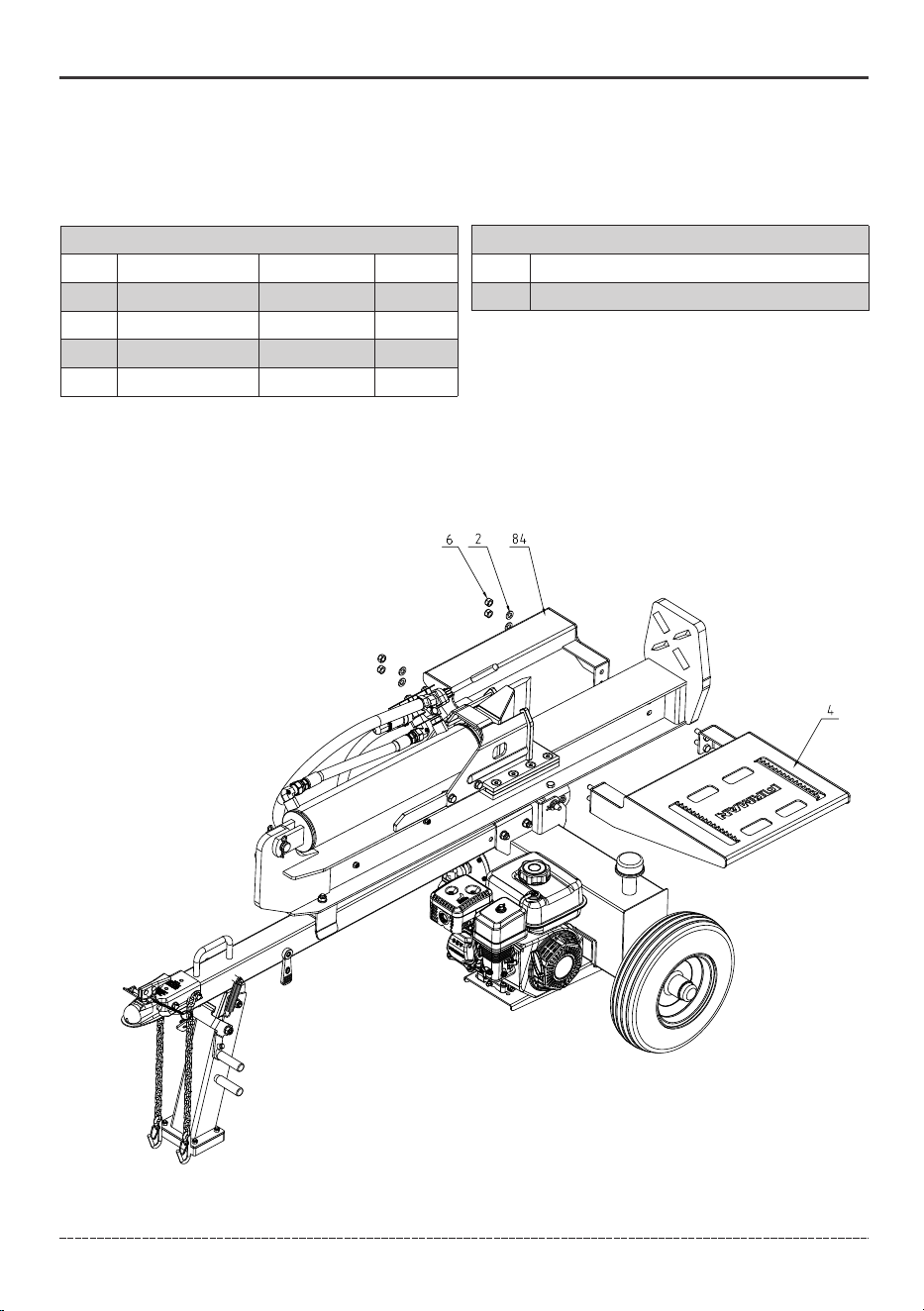
Step 8: Install the Log Cradle and Log Table
Attach the Log Cradle (84) and Log Table(4) to the beam, secure using M12 lock nuts (6)and 12mm
flat washers (2) (torque to 51.6lbf-ft (70 N.m)).
Parts List
Ref. #
Description
Part #
Washer Ø12
Lock Nut M12
Log Cradle
Log Table
2
6
84
4
710717007
710717008
710718286
710718464
Tools
Ref. #
Description
1 19mm wrench and/or socket ratchet
QTY.
4
4
1
1
NOTICE The bolts used in this assembly step are welded to the log table.
20
English Customer Service: 1-844-FIRMAN1
1. Location
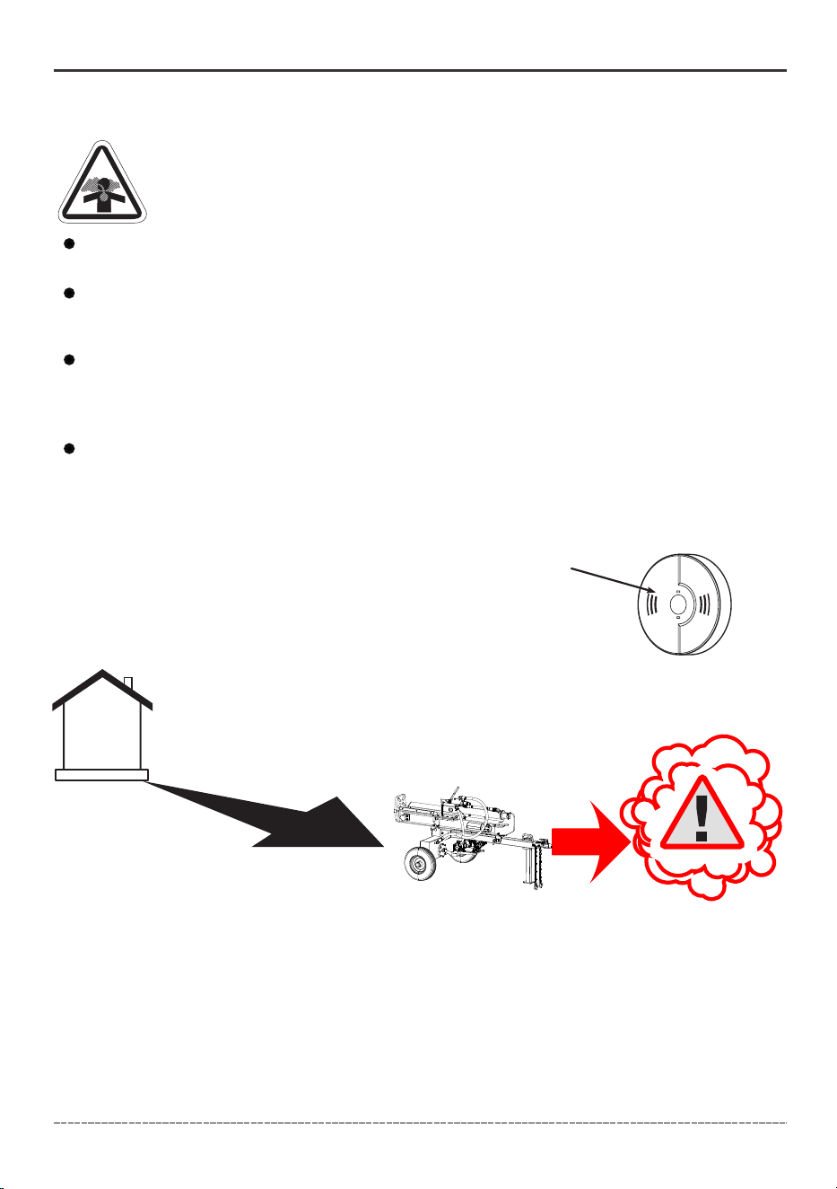
DANGER! Engine exhaust contains carbon monoxide, a poisonous gas that could kill
you in minutes. You CANNOT smell it, see it, or taste it. Even if you do not smell exhaust
fumes, you could still be exposed to carbon monoxide gas.
Carbon Monoxide Alarm(s)
Install carbon monoxide alarms inside your home. Without working
carbon monoxide alarms, you will not realize you are getting sick and
dying from carbon monoxide poisoning.
20 ft. (6 m) min.
OPERATION
Install battery-operated carbon monoxide alarms or plug-in carbon monoxide alarms with
battery back-up according to the manufacturer's instructions. Smoke alarms cannot detect
carbon monoxide gas.
Do not run this log splitter inside homes, garages, basements, crawlspaces, sheds, or other
partially enclosed spaces even if using fans or opening doors and windows for ventilation.
Carbon monoxide can quickly build up in these spaces and can linger for hours, even after this
product has shut off.
If you start to feel sick, dizzy, weak or your home’s carbon monoxide alarm sounds, get to fresh air
right away. Call emergency services. You may have carbon monoxide poisoning.
Prevent Carbon Monoxide (CO) Poisoning
Use outdoors and downwind at least 20 ft. (6 m) from any home.
Point exhaust away from all homes and occupied spaces.
Install CO alarms inside your home.
Operate log splitter only outdoors and downwind at least 20 ft.(6 m) from occupied spaces with
exhaust pointed away to reduce the risk of carbon monoxide accumulating.

21
English Customer Service: 1-844-FIRMAN1
Reduce Risk of Fire
WARNING! Exhaust heat/gases could ignite combustibles, structures or damage fuel
tank causing a fire, resulting in death or serious injury.
OPERATION
5 ft.(1.5 m)
min.
5 ft.(1.5 m)
min.
20 ft.(6 m) min.
Keep log splitter at least 5 ft. (1.5 m) from any structure, trees or vegetation over 12 in. (30 cm)
in height.
Select an outdoor site that is dry and protected from the weather. Do not move log splitter
indoors to protect it from the weather.
Do not locate the log splitter under a deck or other similar structure that may confine heat and
airflow.
22
English Customer Service: 1-844-FIRMAN1
2. Oil and Gasoline
Add Engine Oil
NOTICE Do not attempt to crank or start the engine before it has been properly filled with the
recommended type and amount of oil. Damage due to operation with no oil will void your warranty.
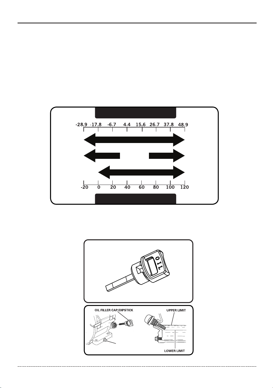
Degrees Celsiusº(Outside)
Full Synthetic 5W-30
Degrees Fahrenheitº(Outside)
5W-3010W-40
10W-30
1.Place log splitter on a flat, level surface.
2.Clean area around oil fill and remove yellow oil fill cap/dipstick.
3.Wipe dipstick clean.
OPERATION
(H)
DRAIN PLUG
(L)
H
L
We recommend using SAE 10W-30 API SJ or higher oil for best performance. Do not use special
additives. Ambient temperature determines the proper oil viscosity for the engine. Use the chart
to select the proper oil for the outdoor temperature range expected.

23
English Customer Service: 1-844-FIRMAN1
4. Using oil funnel, slowly pour contents of provided oil bottle into oil fill opening until oil reaches
upper limit "H" mark on the dipstick. Be careful not to overfill. Overfilling could cause engine
starting problems or engine damage.
5.Replace oil fill cap/dipstick and fully tighten.
6.Oil level should be checked prior to each use or at least every 8 hours of operation. Keep oil
level maintained.
The log splitter is equipped with a low oil shutdown. If the oil level drops below the minimum
required level, a sensor will activate an internal switch stopping the engine. If the engine shuts off
and the oil level is within specifications, check to see if log splitter is sitting at an angle. Place log
splitter on an even surface to correct this. If engine fails to start, the oil level may not be high enough
to deactivate the internal low oil level switch. Make sure the sump is completely full of oil to the
upper limit (H). Do not operate engine until oil level issue is corrected. Contact FIRMAN customer
service.
Low Oil Shutdown
Add Gasoline
WARNING! Fuel and its vapors are extremely flammable which could cause burns or fire
resulting in death or serious injury.
Turn engine OFF and let it cool at least 2 minutes before removing fuel cap.
Do Not refuel or move log splitter when engine is running.
Move log splitter outdoors prior to adding or draining fuel.
Keep fuel away from any ignition sources.
Do not overfill tank, allow space for fuel expansion.
If any fuel spills, wait until it evaporates before starting engine.
Check and replace fuel lines, tank, cap, and fittings prior to each use if any damage or leaks
are found.
Fuel must meet these requirements:
Clean, fresh, unleaded gasoline with a minimum of 87 octane.
For high altitude use, see Operation at High Altitude.
Gasoline with no more than 10% ethanol is acceptable.
E10
E15
OPERATION
24
English Customer Service: 1-844-FIRMAN1
NOTICE Do not mix oil in gasoline or modify engine to run on alternate fuels not described in this
manual. Use of unapproved fuels could damage engine and will not be covered under warranty.
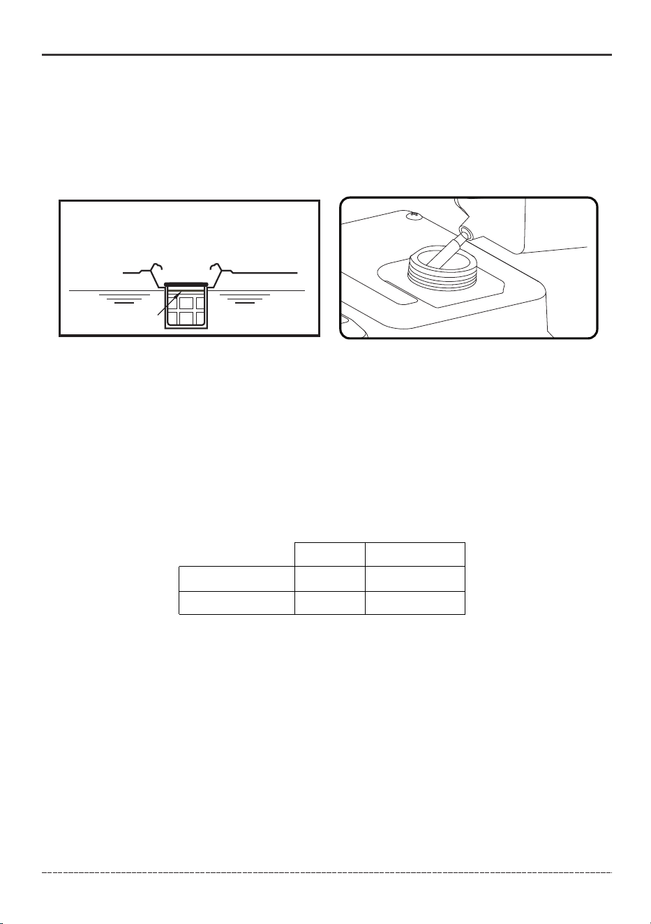
1. Clean area around fuel fill cap, remove cap.
2. Slowly add unleaded fuel to fuel tank. Be careful not to fill above the RED fuel level indicator.
This allows adequate space for fuel expansion.
Red Line Indicator
3. Install fuel cap and let any spilled fuel evaporate before starting engine.
Operation at High Altitude
At altitudes over 5,000 feet (1524 meters), a minimum 85 octane gasoline is acceptable. Engine power
will be reduced approximately 3.5% for every 1000 feet (305 m) of elevation above sea level. High
altitude may cause hard starting, increased fuel consumption and spark plug fouling. To operate at
high altitudes FIRMAN can provide a high altitude carburetor main jet. The alternative main jet and
installation instructions can be obtained by contacting Customer Support.
NOTICE Operation using an alternative main jet at elevations lower than the recommended
minimum altitude can damage the engine. For operation at lower elevations, the standard main
jet supplied must be used. Operating the engine with the wrong main jet may increase exhaust
emissions, fuel consumption and reduce performance.
Altitude main jet 1
Altitude main jet 2
208cc
Altitude
3000-6000Feet
6000-8000Feet
Operation at High Ambient conditions
OPERATION
Your FIRMAN Power Equipment product is designed and rated for continuous operation at ambient
temperatures up to 104°F (40°C). The log splitter may be operated at temperatures ranging from
5°F(-15°C) to 122°F(50°C) for short periods. If the log splitter is exposed to temperatures outside
this range during storage, the log splitter should be brought back within this range before operation.
When operated above 77°F(25°C) there may be a decrease in power. Log splitter cycle time and ram
force are subject to and limited by such factors as ambient temperature, altitude, engine conditions
etc.
(914-1828 m)
(1828 - 2438 m)
346713001
346713002
25
English Customer Service: 1-844-FIRMAN1
OPERATION
Add Hydraulic Oil
1.Make sure the log splitter is on a flat, level surface.
2.Remove vent cap (35) from the hydraulic oil tank.
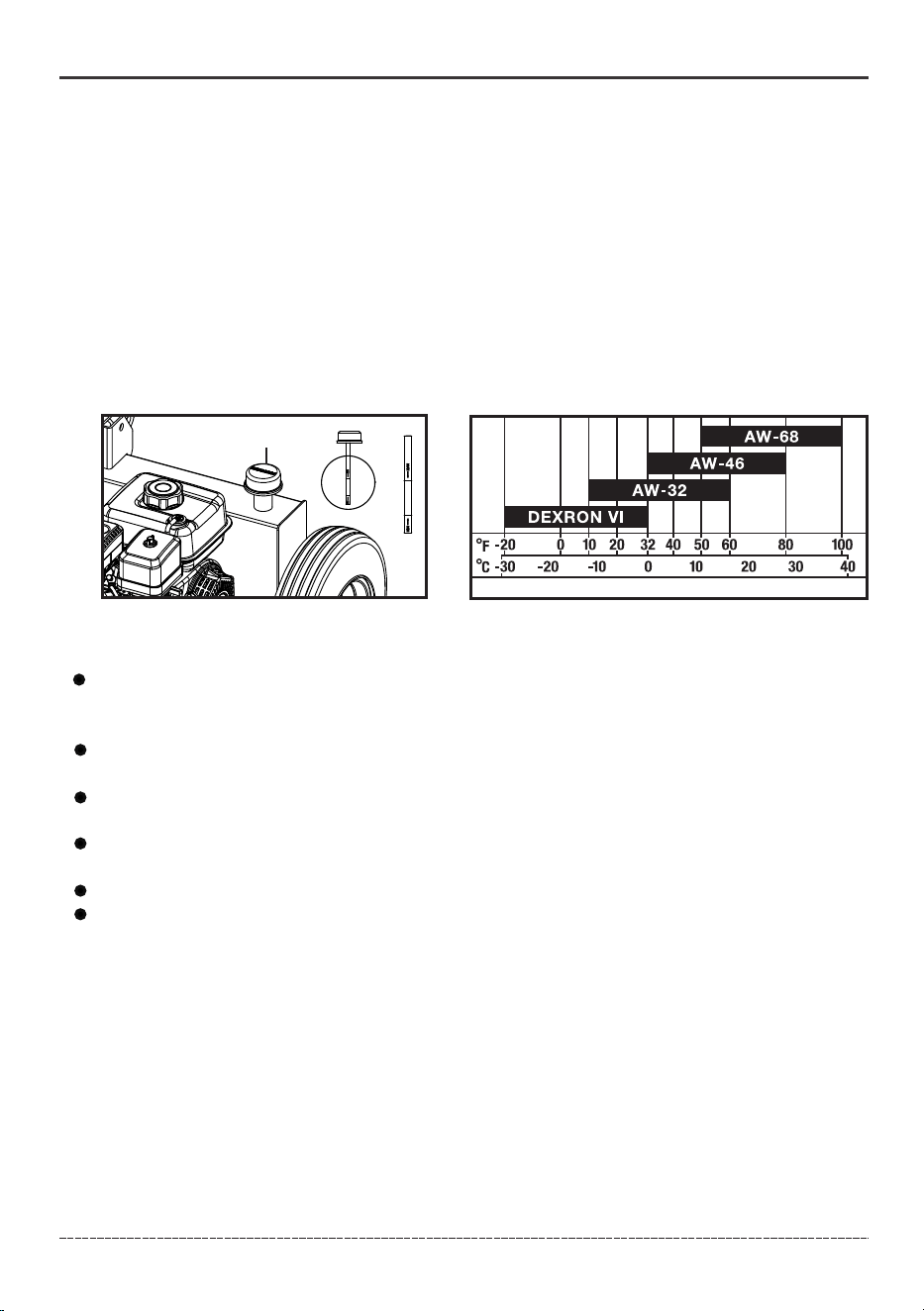
3. Add 7 gal. (27 L) of hydraulic oil. AW32, AW46 & universal hydraulic oil are all acceptable types of
fluid. Automatic transmission fluid can be used when operating in temperatures below 32°F (0°C).
4. Reinstall vent cap (35) after confirming oil level is at the upper-middle position on the dipstick.
Do Not overfill.
5.Start engine and use the control valve handle to extend and retract wedge several times to
remove air from the lines.
6. Reconfirm oil level is at the upper-middle position on the dipstick. Do Not overfill.
7.Check oil level daily and add as needed.
High fluid pressure and temperatures are created in the hydraulic log splitter. Hydraulic fluid will
escape through a pin-size hole opening and can puncture skin and cause severe blood poisoning.
Inspect hydraulic system regularly for possible leaks. Never check for leaks with your hand while
the system is pressurized. Seek medical attention immediately if injured by escaping fluid.
Make sure all fittings are tight and secure before applying pressure. Relieve system pressure
before servicing.
Make sure the hydraulic hoses do not touch any hot surfaces or cutting areas.
Hoses need to be positioned were they are clear from the engine and cutting wedge. To avoid
death or serious injury always inspect the hoses before operating the log splitter.
WARNING! Failure to follow these instructions could result in death or serious injury.
DO NOT remove the hydraulic oil vent cap (35) when the engine is running or oil is hot. Hot oil can
escape causing severe burns. Always allow the log splitter to cool completely before removing the
hydraulic oil vent cap.
35

26
English Customer Service: 1-844-FIRMAN1
OPERATION
Before Each Use Inspect the Log Splitter
WARNING! Before operating or using the log splitter, read and follow the instructions below
and all safety information. Failure to follow these instructions could result in death or serious
injury.
ALWAYS use the log splitter for its intended use.
ONLY use the log splitter to split wood logs, length wise with the grain.
NEVER modify, alter or change the log splitter in any way, modifications will void the warranty.
NEVER attach a rope, cable or other device to the control lever on the log splitter.
Only operate the log splitter in daylight or good artificial light.
NEVER leave the log splitter unattended while the engine is running.
DO NOT change the splitting position with the engine running. Contact with the muffler can
cause serious burns.
1. Check the hydraulic oil level and visually inspect all hoses, attachments and cylinder for loose
fittings, leaks, cracks, fraying or other damage.
2. DO NOT operate the log splitter if there is any indication of damage.
3. Inspect the engine and make sure the oil level is correct before operating. Clean and Inspect the
spark arrestor regularly (follow spark arrestor maintenance schedule).
4. The tires need to be fully inflated and in good condition. Reference the tire sidewall for
recommended tire pressure.
WARNING! Before towing the log splitter, read and follow the instructions below and all safety
information. Failure to follow these instructions could result in death or serious injury.
Making sure the Log Splitter is securely attached to the vehicle is the responsibility of the
owner/operator.
Failure to securely attach the Log Splitter can cause loss of control of the vehicle or the log
splitter being separated from the towing vehicle.
Move the fuel shutoff to “OFF” before towing the log splitter.
DO NOT over inflate tires. Serious injury can result if tires fail.
DO NOT tow the log splitter if the tires are worn or will not hold air.
DO NOT exceed the maximum 45 MPH (72 KM/H) towing speed and check local, state, and
federal requirements before towing on any public road.
Always use safety chains. Secure and lock the log splitter to the vehicle hitch before moving.
Drive safely. Be aware of the added length of the log splitter. When backing up, using a spotter
outside the vehicle is recommended.
Never ride or transport cargo on the log splitter.
Turn off the vehicle before leaving the log splitter unattended.
Block the log splitter wheels to prevent unintended movement.
ALWAYS disconnect your log splitter from the towing vehicle before operating it.
Do not tow the log splitter at night or in low visibility.
ALWAYS make sure the beam is in the locked position when splitting in the horizontal or vertical
orientation.
DO NOT let the beam drop as it could crush fingers or cause damage to the log splitter.
NEVER operate or let anyone else operate, the log splitter while under the influence of alcohol,
drugs, or medication.
27
English Customer Service: 1-844-FIRMAN1
OPERATION
Changing Beam from Horizontal to Vertical Orientation
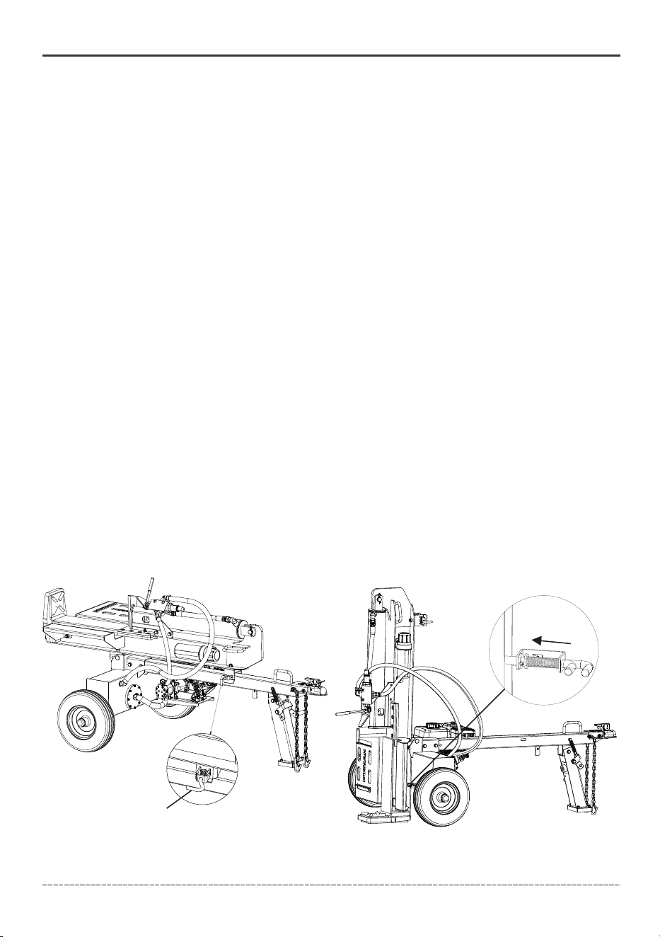
When logs are too heavy to lift, the log splitter beam can be changed to the vertical orientation.
Always allow the log splitter to cool completely before changing from horizontal to vertical
orientation.
To change from horizontal to vertical orientation:
To change from vertical to horizontal orientation, reverse steps.
Pin
Figure A
Figure B
NOTICE When attaching the Safety Chains, Attach the left chain to the right anchor of the tow
vehicle and the right chain to the left anchor of the tow vehicle so that that the Safety Chains cross
each other under the Ball Hitch.
When you place the receiver onto the ball and lock into place, the receiver should not have vertical
movement. There should be resistance to the latch assembly when locking.
5. Insert a receiver Locking Pin, not provided, into the hole in the Latch Assembly.
Transporting the Log Splitter
WARNING! The beam is extremely heavy and shall only be handled with 2 or more people. To avoid
muscle strain or back injury, DO NOT try and lift or handle the beam without assistance.
Figure B
NOTICE The beam should only be in the vertical position on flat ground. Uneven ground can cause
the beam to be unstable.
1. Disengage horizontal beam pin that locks the beam to the tongue (figure A).
2. Standing alongside the hydraulic cylinder, (opposite side from the engine) firmly grasp the
handle on the beam and lift upward while pushing the beam back until upright. Once the beam
is upright, lock the beam (figure B).
1. Lower the beam to its horizontal position. Make certain the beam is locked securely with the horizontal
beam pin.
2. Rotate the tongue stand to the horizontal position for transportation.
a) Use your hand or foot and rotate the tongue lock counterclockwise. The stand is free to rotate under
the tongue.
b) With the help of another person, support the tongue and pivot the tongue stand up to the transporting
position.
c) Use the the rubber strap to prevent the stand from inadvertently dropping during towing.
3. Pull the Latch Assembly on the Receiver up and into the open position. Position the Receiver of the Log
Splitter over and onto the tow vehicle’s 2" (51 mm) tow ball.
4. Close the Latch Assembly on the Receiver to lock it onto the Tow Ball. Attach the towing Safety
Chains (81) to the tow vehicle ensuring there is enough slack for turning.
28
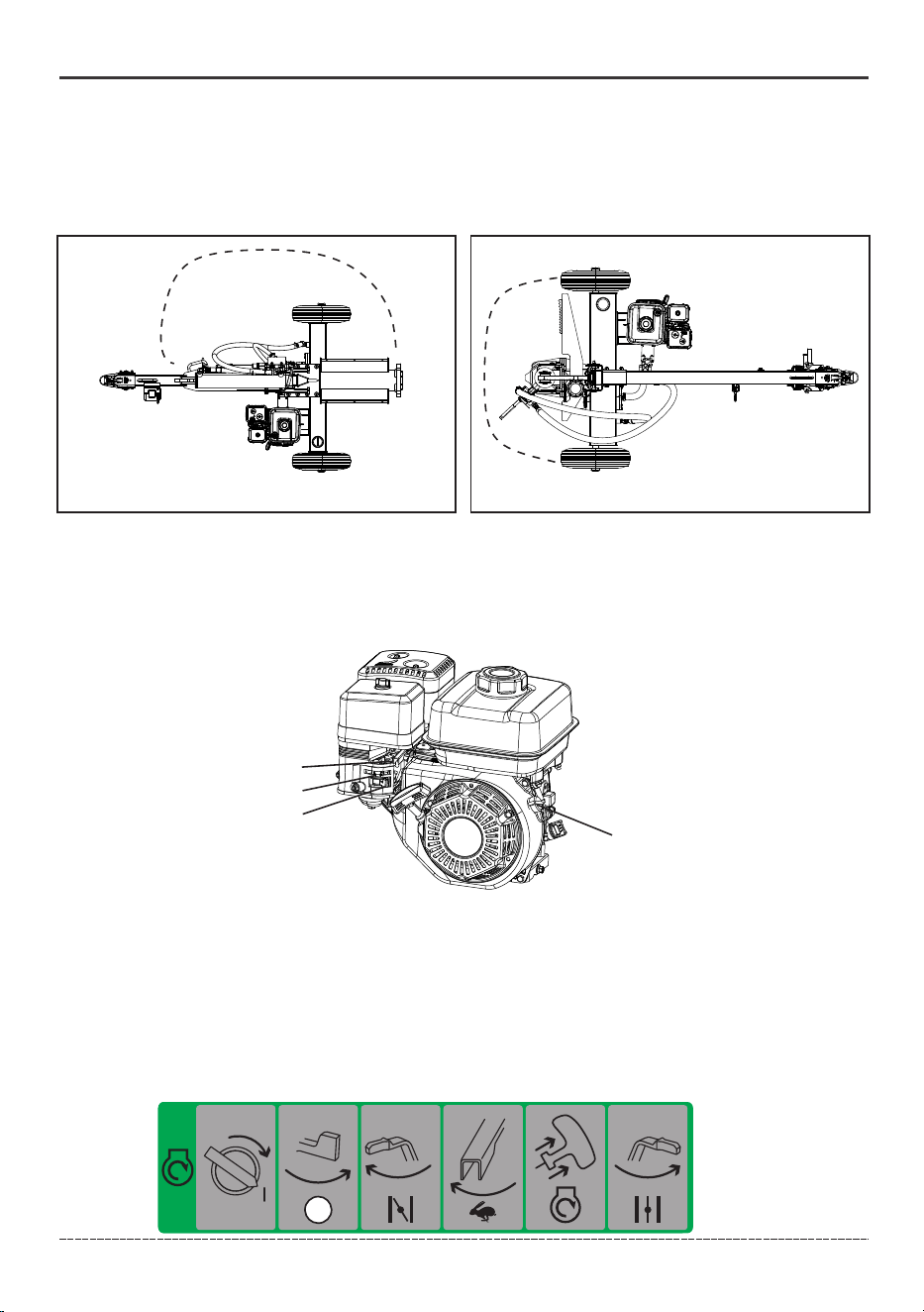
1. Before using the log splitter, check for loose or missing parts and for any damage which may
have occurred during shipment. Ensure spark plug, muffler, fuel cap, and air cleaner are all in place.
2. Move log splitter outdoors to safe operating location downwind and at least 20 feet from any
occupied spaces.
3. Rotate engine switch (A) to “ON”(I) position.
4. Move the fuel valve (B) to the “ON” position.
5. Move the choke lever (C) to the “Choke” position.
6. Move the throttle lever (D) to the “Fast” position.
7. Pull the starter cord slowly until resistance is felt and then pull rapidly.
8. As engine warms up, move the choke lever (C) to “Run” position.
English Customer Service: 1-844-FIRMAN1
OPERATION
A
B
C
D
Starting the Engine
The log splitter must have at least 5 feet of clearance from combustible material. The log splitter
needs to be on a dry and level surface with good footing. Do not work in mud, ice, brush or snow.
When using the log splitter the operator zone must be maintained at all times.
Only operate log splitter from operator zone shown below.
Horizontal
Vertical
OPERATOR
ZONE
OPERATOR
ZONE
29
English Customer Service: 1-844-FIRMAN1
Stopping the Engine
1. Rotate the engine switch(A) to the"OFF" position.
2. Move the fuel valve(B) to the "OFF" position.
Always ensure that the Fuel Valve and the Engine Switch are in the “OFF” position when the
engine is not in use.
OPERATION
After pump has cooled, remove the priming plug and pump drain plug and allow the pump to
drain thoroughly.
NOTICE Drain water from pump after use. Trapped water could freeze and damage pump. Pump
damage caused by freezing is not covered by warranty.
After each use:
1. Drain pump housing.
2. Disconnect and drain hoses.
3. Clean pump with dry cloth.
4. Store pump in clean, dry area.
5. If storing for more than 30 days, see long term storage.
AFTER EACH USE
Flush the pump with clean water after each used is advised. This will help to extend the life of the
pump as some materials pumped may leave residue that could corrode parts, build up over time,
or cause harm to any plants, animals or humans. Flushing the pump will help to reduce any damage
and dangers caused by pumping chemicals and pesticides.
Log Splitter Operation
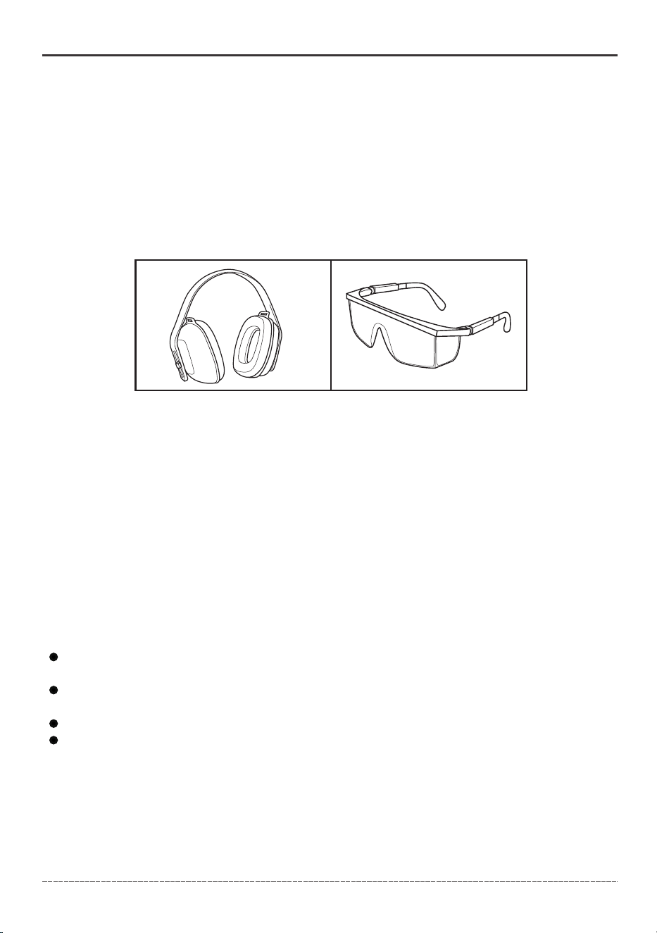
1. ALWAYS wear eye and ear protection, safety shoes or heavy boots, gloves, and protective clothing.
2. Block tires and ensure support leg is secure to prevent unintended movement of the log splitter
during operation.
3. Set log splitter in either the horizontal or vertical position.
NOTICE HORIZONTAL position is used for lighter logs that can easily be loaded onto the beam.
VERTICAL position is used for light logs as well as heavy logs that are difficult to load onto the beam.
Back injury can result from lifting logs onto the log splitter if proper lifting techniques are not used.
If the oil is foamy that means there is air mixed in with the oil. Not enough fluid in the tank and
the splitting will not be consistent, loss of splitting power can result.
If a log gets stuck, embedded or will not split completely, push the control handle in the
reverse direction and allow the log splitter to strip the log from the wedge.
ALWAYS keep hands clear of the log and wedge while it is retracting.
The hydraulic cylinder stroke is designed so the wedge stops approximately 1.2 in.(3.0 cm)
from the foot plate.
4. Before use, verify that the beam is locked in the horizontal or vertical position. The pin on the
beam lock must be engaged with the tongue to prevent the beam from inadvertently rotating.
5. Load a log onto the beam against the foot plate (MAX LOG LENGTH – 20.5 in.[52 cm]).
6. Make sure all limbs are clear of crush zones.
7. Push the control valve handle forward (towards the foot plate) to split the log.
8. Push the auto control valve handle backward to return the wedge to its original position.
9. Clear the split wood from the operator zone.

30
English Customer Service: 1-844-FIRMAN1
Maintenance - Storage
General Recommendations
Regular maintenance will improve the performance and extend the life of the log splitter. See any
authorized dealer for service.
The log splitter's warranty does not cover items that have been subjected to operator abuse or
negligence. To receive full value from the warranty, the operator must maintain the log splitter as
instructed in this manual.
Some adjustments will need to be made periodically to properly maintain your log splitter.
All service and adjustments should be made at least once every year. Follow the requirements
in the maintenance schedule above.
NOTICE Once a year you should clean or replace the spark plug and replace the air filter. New
spark plug and clean air filter assure proper fuel-air mixture and help your engine run at peak
performance and last longer.
To be performed by knowledgeable/experienced owner or by authorized service center.
*
MAINTENANCE SCHEDULE
ITEMNOTES
Daily(Before
operation)
Initial
25 hours
Every
50 hours
Every
100 hours
(or annual)
Fittings/
Fasteners
Spark Plug
Engine Oil
Air Filter
Fuel Line
Exhaust
System
Engine
Check condition. Adjust gap
and clean. Replace if necessary.
Check oil level.
Clean, replace if necessary.
Check for leakage. Retighten or
replace gasket if necessary.
Check adjust valve clearance.
Clean combustion chamber.
Check. Replace if necessary.
Check fuel hose for cracks or other
damage. Replace if necessary.
Replace.
Check spark arrester screen.
Clean/Replace if necessary.
Every
250 hours
*
*
Fuel
Clean fuel tank strainer.
Replace if necessary.
Follow the service intervals indicated in the following maintenance schedule.
Service your log splitter more frequently when operating in adverse conditions.
Contact our Technical Support Team at 1-844-347-6261 to locate the nearest FIRMAN service
dealer for your log splitter or engine maintenance needs.
EVERY 8 HOURS OR DAILY
Check engine and hydraulic oil levels
Clean around air intake and muffler
Remove debris from the beam surface. Apply a thin layer of grease or oil to the beam surface
to improve wedge movement and reduce surface rusting.
FIRST 25 HOURS
EVERY 50 HOURS OR EVERY YEAR
Change engine oil
Clean air filter foam element
Change engine oil if operating under heavy load or in hot environments
EVERY 100 HOURS OR EVERY YEAR
Replace air filter
Change engine oil
Clean/adjust spark plug
Check/adjust valve clearance*
Clean spark arrestor
Clean fuel tank and filter*
Change hydraulic oil
Change hydraulic oil filter
EVERY 250 HOURS
Clean combustion chamber*
Inspect wheel bearings and repack bearing grease as needed.
EVERY 3 YEARS
Replace fuel line*
FIRST 50 HOURS
Change the hydraulic oil and oil filter
31
English Customer Service: 1-844-FIRMAN1
ENGINE MAINTENANCE
To prevent accidental starting, remove and ground spark plug wire before performing any service.
Change Engine Oil
Change engine oil every 100 hours. (for a new engine, change oil after 25 hours.)
If you are using your log splitter under extremely dirty or dusty conditions, or in extremely hot
weather change the oil more often.
CAUTION! Avoid prolonged or repeated skin contact with used motor oil. Used motor oil has been
shown to cause skin cancer in certain laboratory animals. Thoroughly wash exposed areas with
soap and water.
KEEP OUT OF REACH OF CHILDREN. DON’T POLLUTE. CONSERVE RESOURCES. RETURN USED OIL
TO COLLECTION CENTERS.
NOTICE We recommend using SAE 10W-30 API SJ oil for best performance. Other high-
quality detergent oils (API SJ or higher) are acceptable. See Oil and Gasoline
Maintenance - Storage
DRAIN PLUG
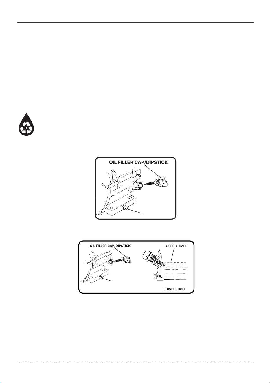
(a) On a level surface drain oil into a suitable container by removing the drain plug and the oil
filler cap while the engine is warm.
(b) Reinstall the drain plug and fill the engine with oil until it reaches the HIGH(H) level on the
oil filler dipstick.
(H)
DRAIN PLUG
(L)
32
English Customer Service: 1-844-FIRMAN1
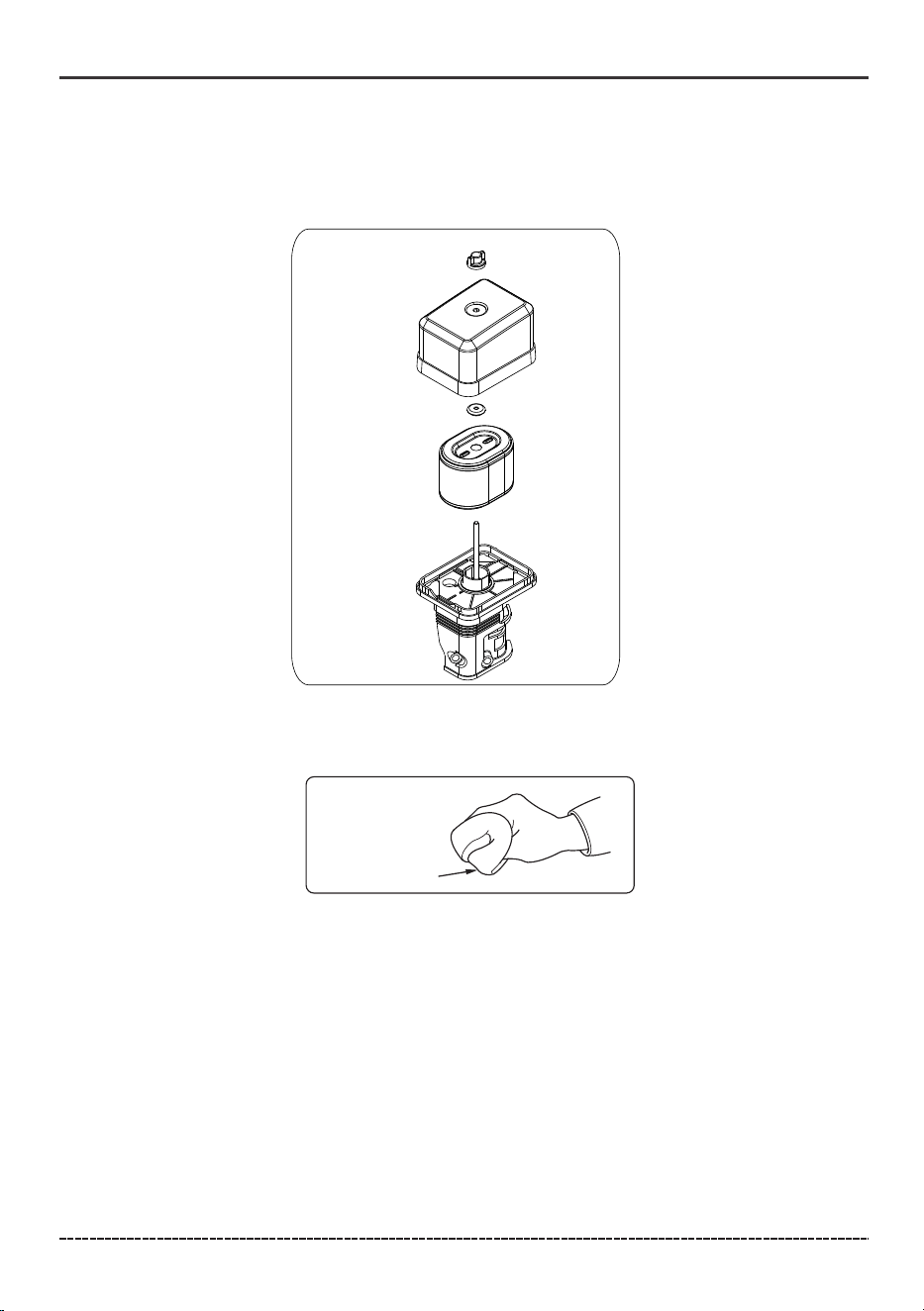
Air Filter Maintenance
( c) Saturate foam element with clean engine oil and squeeze in a clean cloth to remove excess oil.
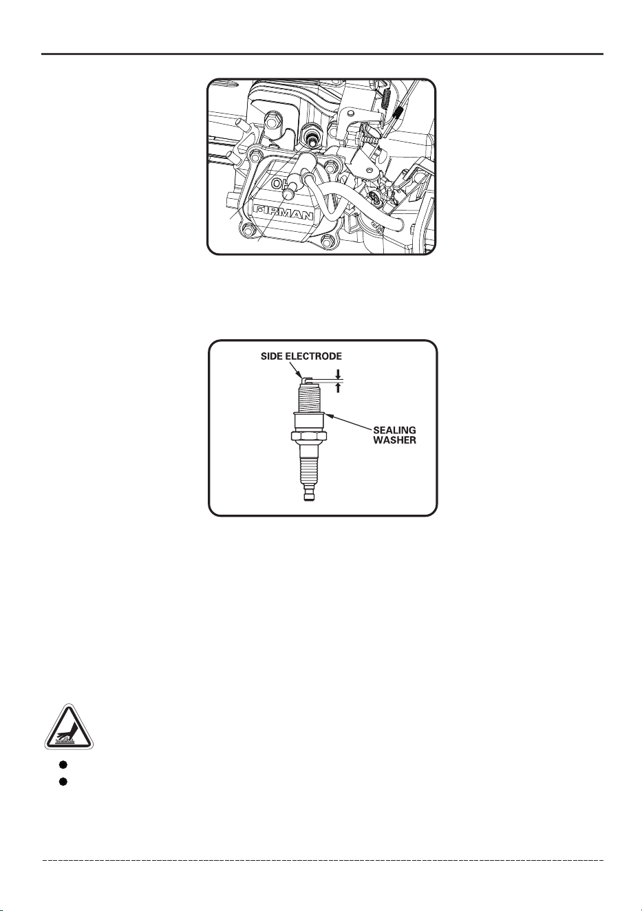
Spark Plug Maintenance
Changing the spark plug will help your engine start easier and run at peak performance.
(a) Remove the spark plug boot.
(b) Remove spark plug using provided wrench.
(d) Reassemble the element. Reattach the air filter cover and tighten wing nut.
Maintenance - Storage
(a) Unscrew wing nut to remove the air filter cover.
(b)Remove the foam element from the air filter and wash in liquid detergent and water.
Squeeze dry in a clean cloth.
FOAM ELEMENT
33
English Customer Service: 1-844-FIRMAN1
Maintenance Valve Clearance
Intake: 0.004 – 0.006 in. (0.10 – 0.15 mm)
Exhaust: 0.004 – 0.006 in. (0.10 – 0.15 mm)
Muffler and Spark Arrester
WARNING! Contact with muffler area could cause burns resulting in serious injury.
Do not touch hot parts.
It is a violation of California Public Resource Code, Section 4442, to use or operate the engine
on any forest-covered, brush-covered, or grass-covered land unless the exhaust system is
equipped with a spark arrester, as defined in Section 4442, maintained in effective working
order. Other states or federal jurisdictions may have similar laws, reference Federal
Regulation 36 CFR Part 261.52.
Maintenance - Storage
A- Spark plug
B- Spark plug boot
A
B
( c) Inspect spark plug for damage and clean with a wire brush before reinstalling. Replace if
damaged.
(d) Adjust the electrode gap to 0.028 - 0.031 in. ( 0.7 - 0.8 mm).
(e) Seat spark plug in position and thread by hand to prevent cross threading.
(f) Tighten plug with provided wrench and put the spark plug boot back on spark plug.
0.028-0.031 in.
(0.7-0.8mm)
SPARK PLUG: TORCH F6RTC or equivalent
34
English Customer Service: 1-844-FIRMAN1
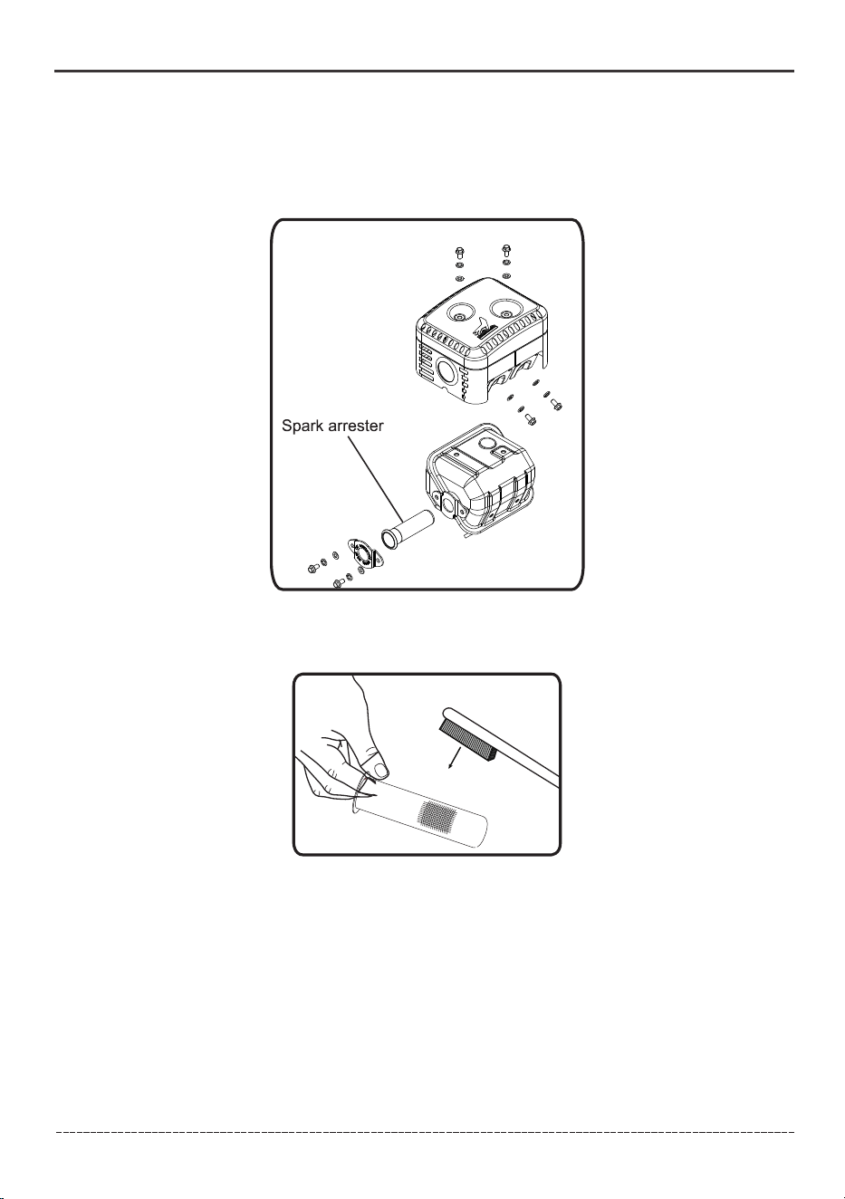
Inspect Muffler and Spark Arrester
1. Inspect the muffler for cracks, corrosion, or other damage.
2. Remove the screws securing the spark arrester in place and the remove it from muffler.
3. Carefully remove the carbon deposits from the spark arrester screen with a wire brush.
4. Replace the spark arrester if it is damaged. If replacement parts are required, make sure to use
only FIRMAN original equipment replacement parts.
5. Position the spark arrester in the muffler and attach with the screws.
NOTICE Failure to clean or replace spark arrester may result in decreased engine performance.
Maintenance - Storage
35
Changing the Hydraulic Oil and Oil Filter
English Customer Service: 1-844-FIRMAN1
Maintenance - Storage
1. Confirm that the piston rod of the hydraulic cylinder is fully retracted into the cylinder and the
engine is in the "off" state; close the fuel valve to prevent fuel leakage or accidental startup; move
the control valve handle back and forth several times to release the accumulated pressure in the
system; place a container with a capacity of not less than 7 gallons (27 L) under the hydraulic oil
tank.
2. Locate the oil drain plug at the bottom of the hydraulic oil tank, unscrew and remove it
slowly, and wait for the oil to drain completely into the container. During the drainage process,
observe the oil flow to avoid any spillage.
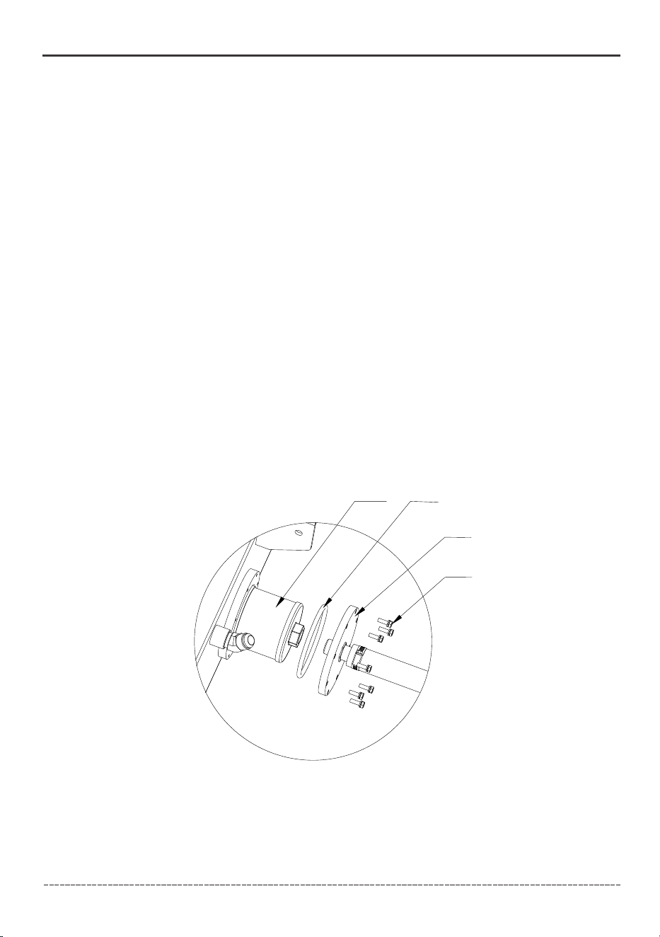
3. Unscrew the M6 screw (43) that fixes the filter flange weldment (42), carefully remove the old
hydraulic oil filter (40) and O-ring (41) from the filter flange (42), and properly dispose of the old
parts in accordance with regulations to avoid pollution.
4. Install the new filter and new O-ring on the filter flange (42) in the correct direction; use a 10mm
wrench to tighten the M6 screw (43) to a torque of 7.38 lbf·ft(10 N.m), avoiding component damage
due to improper torque.
5. Wrap 2-3 turns of new Teflon tape around oil tank drain plug and reinstall. See OPERATION
add hydraulic oil for hydraulic oil specifications and filling instructions.
NOTICE The drain plug (41) is sealed with Teflon tape. Add 2-3 wraps of new Teflon tape as needed
when replacing the drain plug (41) to prevent oil leak.
9. Unscrew and remove the oil fill plug (41), on top of the tank. Add approximately 4 gal. (15.1 L) of
hydraulic oil to the tank. Replace and tighten the oil fill plug (41) and orient the vent hole (B) away
from the operator zone. Wipe up any spilled oil.
10. Start the engine following the procedure described in the OPERATION section. Purge the air
from the system by extending and retracting the wedge several times until the motion is smooth.
11. Check the oil sight glass and add approximately 0.5 gal.(1.9 L) of hydraulic oil to bring the oil
level back up to the oil sight glass (C).
12. Dispose of used oil at approved recycling locations.
WARNING! Always shut off the engine, disconnect the spark plug, and relieve system pressure
before cleaning, adjusting, or servicing the log splitter. Relieve system pressure by moving control
valve handle back and forth several times.
Change the oil and filter after the first 50 hours of use. Then every 100 hours or annually.
For year round use in warmer climates (always ABOVE 32˚F/ 0˚C):
– AW 46
– Universal Hydraulic Oil
For year round use in colder climates (BELOW 32˚F/ 0˚C):
– Automatic Transmission Fluid
A
B
C
1. Confirm that the piston rod of the hydraulic cylinder is fully retracted into the cylinder and the
engine is in the "off" state; close the fuel valve to prevent fuel leakage or accidental startup; move
the control valve handle back and forth several times to release the accumulated pressure in the
system; place a container with a capacity of not less than 4.75 gallons (18 L) under the hydraulic oil
tank.
2. Locate the oil drain plug (41) at the bottom of the hydraulic oil tank, unscrew and remove it
slowly, and wait for the oil to drain completely into the container. During the drainage process,
observe the oil flow to avoid any spillage.
3. Unscrew the M6 screw (46) that fixes the filter flange weldment (45), carefully remove the old
hydraulic oil filter (43) and O-ring (44) from the filter flange (45), and properly dispose of the old
parts in accordance with regulations to avoid pollution.
4. Wrap 2-3 turns of Teflon tape around the sealing part of the new hydraulic oil filter, then install
the new filter and new O-ring on the filter flange (45) in the correct direction; use a 13mm wrench
to tighten the M6 screw (46) to a torque of 10 N.m, avoiding component damage due to improper
torque.
5. Wrap 2-3 turns of new Teflon tape around oil tank drain plug (41) and reinstall. See OPERATION
add hydraulic oil for hydraulic oil specifications and filling instructions.
40
41
42
43

36
English Customer Service: 1-844-FIRMAN1
Maintenance - Storage
Long Term Storage
Do not store fuel near any ignition sources.
When draining fuel move pump outdoors and use a commercially available non-conductive
vacuum siphon. Fuel must be drained into an approved container.
WARNING! Fuel and its vapors are extremely flammable which could cause burns
or fire resulting in death or serious injury.
If the log splitter will not be used for more than 30 days, prepare it for long term storage as follows:
1. Retract the wedge to protect the rod from corrosion.The rod should be retracted after every use.
2. Never store the machine with fuel in the fuel tank inside a building where ignition sources are
present.
3. Drain all fuel completely from the tank, fuel line and carburetor to prevent gum from forming.
If log splitter is stored with fuel in the fuel tank, we recommend using a gas stabilizer to prevent
sediment from gumming up the carburetor. If there is dirt or moisture in the fuel, drain the fuel
tank. Completely fill the tank with fresh, unleaded gas and add the appropriate amount of fuel
stabilizer. Run the engine for a short time to allow the stabilizer to circulate.
4. Before storing the log splitter, stop the engine, wait at least five minutes to allow all parts to cool.
5. Change the engine oil.
6. Remove the spark plug and pour about ½ ounce (14.8 ml) of oil into the cylinder. Pull the engine
recoil slowly to distribute the oil and lubricate the cylinder. Reinstall the spark plug.
NOTICE The use of a pressure washer or a garden hose to clean the log splitter is not recommended.
The use of water will result in corrosion, shortening life and reducing serviceability.
7. Check the wedge slide for nicks and wear. Sharpen if needed.
8. Apply a rust preventative (oil film or equivalent) to any bare metal areas on the wedge slide and
on top of the beam.
9. Using a soft bristle brush, clean the exterior of the unit removing all dirt, grease, or other foreign
material. Remove dirt and debris from the cylinder head cooling fins and muffler area.
10. To prevent rust, touch up painted surfaces if scratched or chipped.
11. Be sure all hoses, nuts, bolts, and screws are securely fastened.
12. Store the log splitter in a dry, protected place. If it is necessary to store outside, cover it with a
tarp of similar protective material (especially the Engine). Avoid storage near corrosive materials.
37
Troubleshooting – Specifications
English Customer Service: 1-844-FIRMAN1
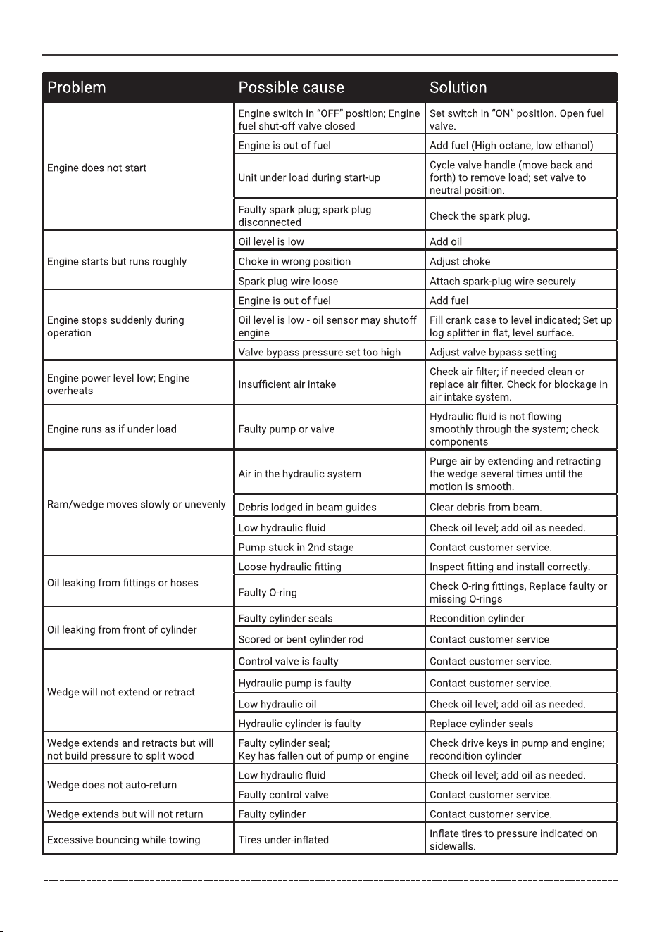
Problem
For all other issues, contact authorized dealer or Firman customer service.
Solution
Cylinder rod will not move.
Slow cylinder rod speed when extending or
retracting
Log will not split or splits extremely slowly
Valve will not stay in detent or will not kick
out of detent position
Engine bogs down during splitting
Engine stalls under low load condition
Engine will not start
Engine is difficult to turn over and will not
start when cold
Engine runs but cylinder does not move
Cause
Solution
Check and replace coupler
A-Insufficient oil to pump Check oil level in reservoir
B-Air in oil
C-Low engine oil
D-Blocked hydraulic lines
E-“ON”/“OFF”
F-Fuel shut off in “OFF” position
Check oil level in reservoir
Check and add engine oil
Check for restriction
Move to “ON” position
Move to “ON” position
G-Damaged control valve
Return control valve for authorized repair
H-Detent setting incorrect
Remove plastic cap on valve and adjust
detent kick out pressure
I-Internally damaged cylinder
Return cylinder for authorized repair
J-Cold ambient temperature
Cold weather can result in slow hydraulic cylinder
operation.Change to recommended hydraulic oil.
K-Broken pump / Engine coupler
L-Defective pump or engine Contact service center
A,D
A,B,D,I
A,B,D,G,I
H
This is normal
L
C,E,F
J
D,K

38
SPECIFICATIONS
English Customer Service: 1-844-FIRMAN1
Troubleshooting – Specifications
Model
GS2801
Ram Force
Cycle Time
Hydraulic Tank Capacity
Max Log Length
Coupler Ball Size
Tire Size
Max towing speed
Cylinder size
Gear Pump
Control Valve
Net Weight
Height
Width
Length
28 Ton
7.5 seconds
7 gal (27 L)
20.5 in. (52 cm)
2 in. (5.1 cm)
16 in. (40.6 cm)
45 MPH (72 KM/H)
4.13 in. (10.5 cm )
2-stage
Detent (auto-return)
518 lb. (235 kg)
42.7 in. (108.6 cm)
46.9 in. (119.2 cm)
83.7 in. (212.5 cm)
Engine
Model
Displacement
Type
Start Type
Oil Capacity
Gasoline Capacity
SPE210
208 cc
4-Stroke OHV
Recoil
20.3 fl. oz (600ml)
0.9 gal (3.2L)
39
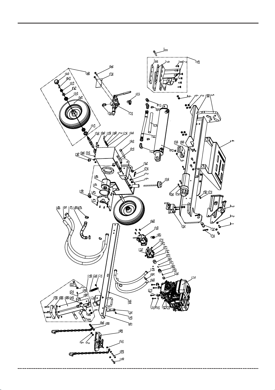
PARTS DIAGRAM AND PART LIST
GS2801 PARTS DIAGRAM
English Customer Service: 1-844-FIRMAN1
Parts Diagrams - Parts Lists
40
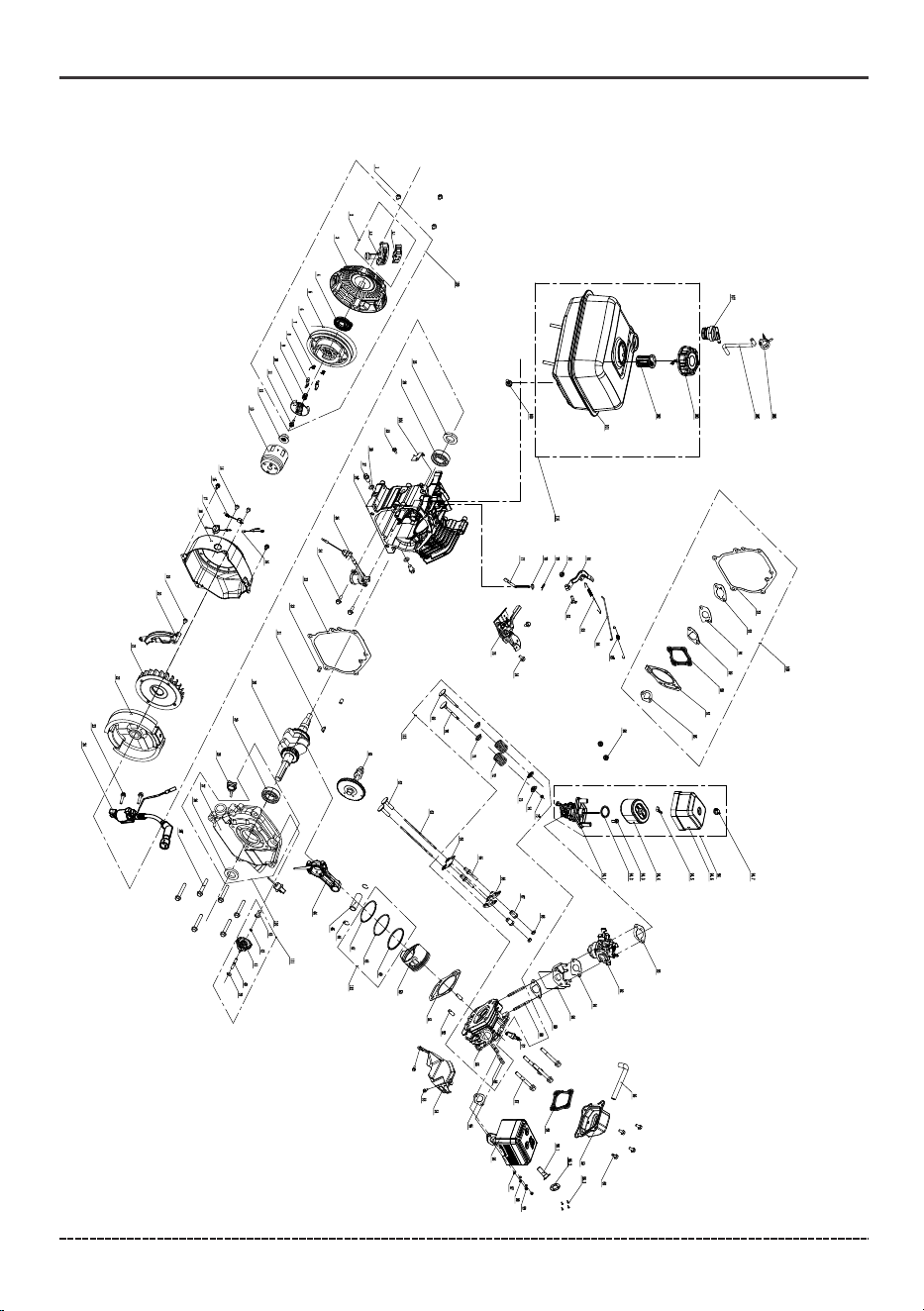
208cc ENGINE PARTS DIAGRAM
Parts Diagrams - Parts Lists

41
GS2801 LOG SPLITTER
English Customer Service: 1-844-FIRMAN1
Parts Diagrams - Parts Lists
NO.
Part Number
Description
Qty.
1
2
3
4
5
6
7
8
9
10
11
12
13
14
15
16
17
18
19
20
21
22
23
24
25
26
27
28
29
30
31
32
33
34
35
36
37
38
39
40
41
42
43
44
45
46
47
48
49
50
51
52
53
54
710717103
710717007
710718290
710718464
710718451
710717008
710718477
710718000
710718344
710718478
710718009
710418008
710718201
710728001
710728020
710728016
710717059
710718002
710718252
710718003
710728043
710717068
710717044
710718284
710717113
710418026
710418002
710718202
710717094
710718041
710718356
710718317
710717133
710718032
710418032
710718008
710717003
710717075
710718314
710718362
710728007
710718309
710718014
710718205
710718033
710728006
710728003
710728002
710728004
710728005
710717024
710717023
710718097
710717032
Bolt M12X35
Washer Ø12
Log Table
Beam
Lock Nut M12
Bolt M12X40
Plate, Wedge Spacer
Bolt M12X90
Hydraulic Cylinder
Hydraulic Pressure Hose
Cable Tie
Bolt M12X30
Beam Pivot Bracket
Bolt M8X25
Manual Canister
Washer Ø6
Lock Nut M8
Hydraulic Cylinder Pin
Pin Clip
Beam Locking ,Assy
Control Valve
Valve Instruction Plate
Bolt M8X12
Hydraulic Oil Tank
Beam Pin
Bolt M12X110
Washer Ø16
Vent Cap
Bolt M10X55
Washer Ø10
Lock Nut M10
Axle
Suction Filter
O-ring
Filter Mounting Plate
Bolt M6X20
Clamp
Suction Hose
Hydraulic Return Hose
Hydraulic Hose Sheath
Hydraulic Pressure Hose
Hydraulic Hose Sheath
Axle Cap
Cotter Pin 4X36
Castle Nut M20×2.5
Washer Ø20
4
19
1
1
1
14
1
8
2
2
1
1
3
1
1
6
1
2
1
4
1
7
3
1
3
1
1
1
1
2
1
1
4
1
1
4
13
5
2
1
1
1
8
1
2
1
1
1
1
1
2
2
2
2
NO.
Part Number
Description
Qty.
55
56
57
58
59
60
61
62
63
64
65
66
67
68
69
70
71
72
73
74
75
76
77
78
79
80
81
82
83
84
85
86
87
88
89
90
91
92
93
94
95
96
97
98
99
100
Wheel Bearing
Wheel
Grease Seal
Bolt M8×30
Pump
Weldment, HD Tongue
Bolt 5/16".-24 x 1"
Lock Washer Ø8
Washer Ø8
Pump Coupler
Set Screw M6×10
Flat Key 3.2×3.2×25
Engine Coupler
Flat Key 4.78×4.78×35
Engine Bushing
Engine
Bolt M8×40
Engine Mounting Bracket
Pump Mount
Spring Pin, 6×35
Spring Retaining Screw
Spring
Washer, Plastic Spacer
Tongue Stand
Safety Chain with Hook
2-in. Ball Coupler
Bolt M10×115
Log Cradle
Bolt M6×25
RUBBER GRIP
Bolt M8×30
Weldment, Stand Lock
Bolt M12×105
Bolt M12×125
Bolt M6×25
Tank Drain Plug
Wedge Assy
Wheel Assy.
Tongue Stand Assy.
Complete Tongue Assy.
710717025
710727001
710717026
710717039
710418000
710718207
710718363
710717041
710717048
710717045
710718316
710717053
710717054
710717043
710717047
710717046
710467002
710718006
710718224
710718221
710717064
710728029
710718038
710718312
710728032
710718367
710717137
710418001
710718077
710718286
710718053
710728033
710728030
710728031
710718054
710718373
710718078
710718076
710718040
710718013
710718471
710718472
710418035
710418034
710418042
710418048
4
2
2
4
1
1
1
4
4
20
1
2
1
1
1
1
1
4
3
1
1
1
2
2
4
1
2
1
1
1
1
1
2
1
4
1
1
1
1
1
1
1
1
2
1
1
Hydraulic Fitting(3/4"NPT-3/4"JIC)
Hydraulic Fitting (1/2"NPT-1/2"JIC)
Weldment, Stripper Cradle
Plate, Wedge Lower Mount
Hydraulic Fitting(3/4"NPT-3/4"JIC)
Hydraulic Hose Sheath, 280mm
Hydraulic Fitting(3/4"NPT-3/4"NPT)
Hydraulic Cylinder Pin Shaft
Hydraulic Fitting(3/4"NPT-1/2"JIC)
Rubber Strap, Tongue Stand
Rubber Bumper, Tongue Stand
Rubber Foot, Tongue Stand
Pull Pin, Vertical Beam Lock
Compression Spring, Vertical Pull Pin
Weldment, Wedge, Medium

42
NO.
Part Number
Description
Qty.
1
2
2.1
2.2
3
4
5
6
7
8
9
10
11
12
13
14
15
16
17
18
19
20
21
22
23
24
25
26
27
28
29
30
31
32
33
34
35
36
37
38
39
40
41
42
43
44
45
46
47
48
336718308
302423001
335725581
335725582
302467013
336723586
336723587
336723588
336723589
336723590
336723592
336723591
336723593
330713555
302467002
336718302
312715031
302457001
302767004
710467003
336723577
336723578
302467001
710467004
336718311
710467005
336723514
336723513
302467005
336723511
336723505
302467006
336723507
317723516
336723510
336718301
340718300
710767001
330723536
336723545
336723595
336723594
336723596
336723597
336723598
336723515
336723517
336723516
336723519
336723520
Flange Bolt M6 x 8
Grip, Starter
Handle Core
Recoil Starter Handle
Recoil Starter Case
Recoil Starter Spring
Rope, Recoil
Recoil Starter Reel
Spring, Ratchet
Ratchet, Starter
Spring, Ratchet Guide
Pawl Guide
Screw, Pawl Guide
Nut M14
Pulley, Starter
Flange Bolt M6 x 12
Diode Assy.
Harness Subassy.
Engine Switch
Engine Shroud
Flange Bolt M6 x 20
Air Guide, Right Side
Cooling Fan
Flywheel
Flange Bolt M6 x 29
Ignition Coil
Flange Bolt M8 x 32
Seal, Oil
Crankcase Cover
Oil Dipstick
Bearing 6205
Crankshaft
Woodruff Key
Dowel Pin
Gasket, Crankcase
Flange Bolt M6 x 12
Sensor, Engine Oil
Crankcase
Drain Plug
Drain Plug Seal
Washer
Governor, Gear Shaft
Gear, Governor
Clip, Govorner Gear
Bushing, Govorner Gear
Rod, Connecting
Pin, Piston
Piston Pin Retainer Ring
Ring Set, Oil
Ring, Second Ring
3
1
1
1
1
1
1
1
2
2
1
1
1
1
1
4
1
1
1
1
1
1
1
1
2
1
6
2
1
2
2
1
1
2
1
4
1
1
2
2
1
1
1
1
1
1
1
2
1
1
English Customer Service: 1-844-FIRMAN1
Parts Diagrams - Parts Lists
NO.
Part Number
Description
Qty.
336723521
336723518
336723003
330723548
336723522
336723523
710467006
336723539
336723527
336723524
336723525
336723526
302467018
340718301
340718302
336723538
336723537
336723531
336723529
336723528
336723541
336723542
336723536
336723535
336723533
340718303
336723532
302767017
336723563
336723564
336713590
336723555
336723005
336723567
336723568
336723569
336723570
312725016
336723556
302467009
336723550
336723551
336723004
710467007
302767019
302467021
302467022
302767022
336723577
302767023
FIRMAN 208cc Engine
49
50
51
52
53
54
55
56
57
58
59
60
61
62
63
64
65
66
67
68
69
70
71
72
73
74
75
76
77
78
79
80
81
82
83
84
85
86
87
88
89
90
91
92
93
94
94.1
94.2
94.3
94.4
Ring, First Piston
Piston
Gasket, Cylinder Head
Locating Pins
Flange Bolt M6 x 8
Air Guide Lower
Cylinder Head
Flange Bolt M8 x 55
Gasket, OHV Cover
Flange Bolt M6 x 15
Governor Gear Assy.
Tappet, Valve
Push Rod
Guide Plate, Push Rod
Bolt, Valve Adjusting
Valve, Rocker
Valve Adjusting Nut
Nut, Valve Lock
Valve, Intake
Valve, Exhaust
Oil Seal, Valve
Spring, Valve
Retainer, Intake Valve
Retainer, Exhaust Valve
Rotator, Exhaust Valve
Governor Assy.
Shaft, Governor Arm
Washer
Cotter Pin
Nut M6
Governor Arm
Bolt, Governor Arm
Spring, Governor
Rod, Governor
Breather Tube
Spark Plug, F6RTC
Intake Stud
Gasket, Insulator
Insulator, Carburetor
Gasket, Carburetor
Carburetor
Gasket, Air Cleaner
Air Cleaner
Air Cleaner Base
Gasket, Air Cleaner Sealing
Flange Bolt M6 x 20
Element, Air Cleaner
1
1
1
2
3
1
1
2
4
1
1
4
1
2
2
1
2
2
2
2
1
1
2
2
1
1
1
1
1
1
1
3
1
1
1
1
1
1
1
2
1
1
1
1
1
1
1
1
1
1
Cover Subassembly, Cylinder Head
Exhaust Valve Stud Bolt M8 x 35
Spring, Throttle Valve Returning

43
English Customer Service: 1-844-FIRMAN1
Parts Diagrams - Parts Lists
NO.
Part Number
Description
Qty.
94.5
94.6
94.7
95
96
96.1
96.2
96.3
97
98
99
100
101
102
103
104
105
106
107
108
109
110
111
112
113
114
357713550
302467023
302767025
302467016
710467008
710767002
710767003
336718359
336713533
336713509
336713534
336713807
302467024
360725512
302467029
336723571
302467025
317713553
710467009
302467036
710467010
302467042
302467039
336423504
302467037
710467011
Wing Nut M6
Air Cleaner Cover
Nut
Muffler Gasket
Muffler Assy.
Spark Arrester
Spark Arrester Holder
Screw ST4.2 x 9.5
Flat Washer Ø8
Lock Washer Ø8
Nut M8
Tank Fitting With Filter
Fuel Tank
Fuel Filter, Wire Mesh
Fuel Cap
Diode Bracket
Hose
Clamp Ø8 x 6
Roll-Over Valve
Gasket Set
Recoil Assy.
Crankcase Assy.
Governor Gear Assy.
Piston Ring Set
Cylinder Head Assy.
Fuel Tank Assy.
1
1
1
1
1
1
1
4
2
2
2
1
1
1
1
1
1
2
1
1
1
1
1
1
1
1

44
English Customer Service: 1-844-FIRMAN1
Service – Warranty
FIRMAN 3 Years Limited Warranty
Do Not Return the Unit to the Place of Purchase
Contact the FIRMAN Service Center and FIRMAN will troubleshoot any issue via phone or e-mail.
If the problem is not corrected by this method, FIRMAN will, at its option, authorize evaluation,
repair or replacement of the defective part or component at a FIRMAN Service Center. FIRMAN
will provide you with a case number for warranty service. Please keep it for future reference.
Repairs or replacements without prior authorization, or at an unauthorized repair facility, will
not be covered by this warranty.
Normal Wear
Your product needs periodic parts and service to perform well. This warranty does not cover
repair when normal use has exhausted the life of a part or the equipment as a whole.
FIRMAN warrants to the original purchaser that the mechanical and electrical components will be free of
defects in material and workmanship for a period of one (1) year(parts and labor) and 3 years (parts
and technical support) from the original date of purchase 90 days [parts and labor] and 180 days [parts]
for commercial & industrial use. Transportation charges on product submitted for repair or replacement
under this warranty are the sole responsibility of the purchaser . This warranty only applies to the original
purchaser and is not transferable.
Repair/Replacement Warranty
Warranty Exclusions
This warranty does not cover the following repairs and equipment.
Warranty Qualifications
Register your product using the QR code provided or at www.firmanpowerequipment.com.
FIRMAN will also register the warranty upon receipt of your Warranty Registration Card and a
copy of your sales receipt from one of FIRMAN’s retail locations as proof of purchase. Please
submit your warranty registration and your proof of purchase within ten(10) days of the date of
purchase.
SERVICE INFORMATION CONTACT FIRMAN PRODUCT SERVICE DEPARTMENT AT 1-844-347-6261
or at www.firmanpowerequipment.com to obtain warranty service information or to order
replacement parts or accessories.
HOW TO ORDER REPLACEMENT PARTS
Even quality-built equipment such as this log splitter may need occasional replacement parts to
maintain it in good condition over the years. To order replacement parts, please give the
following information:
Model No. Rev. Level and Serial No. found on the Data Decal.
Parts number or numbers as shown in the Parts List section.
A brief description of the trouble with the log splitter.

45
English Customer Service: 1-844-FIRMAN1
Service – Warranty
Limits of Implied Warranty and Consequential Damage
FIRMAN disclaims any obligation to cover any loss of time, use of this product, freight, or any
incidental or consequential claim by anyone from using this product. THIS WARRANTY IS IN
LIEU OF ALL OTHER WARRANTIES, EXPRESS OR IMPLIED, INCLUDING WARRANTIES OF
MERCHANTABLILITY OR FITNESS FOR A PARTICULAR PURPOSE.
A unit provided as an exchange will be subject to the warranty of the original unit. The length of
the warranty governing the exchanged unit will remain calculated by reference to the purchase
date of the original unit.
This warranty gives you certain legal rights which may change from state to state. Your state may
also have other rights you may be entitled to that are not listed within this warranty.
Contact Information
You may contact FIRMAN at:
Address
Firman Power Equipment Inc.
Attn: Customer Service
8644 W. Ludlow Dr.
Peoria, AZ 85381
www.firmanpowerequipment.com
We are FIRMAN POWER - And we are here for you.
Installation, Use and Maintenance
This warranty will not apply to parts and/or labor if your product is deemed to have been misused,
neglected, involved in an accident, abused, modified, installed improperly or connected incorrectly.
Normal maintenance is not covered by this warranty.
Other Exclusions
This warranty excludes:
– Cosmetic defects such as paint, decals, etc.
– Wear items such as filter elements, seals, etc.
– Accessory parts such as hoses, hose fittings, etc.
– Failures due to acts of God and other force majeure events beyond the manufacturer’s control.
– Problems caused by parts that are not original FIRMAN parts.

46
English Customer Service: 1-844-FIRMAN1
Service – Warranty
FIRMAN POWER EQUIPMENT INC.
EMISSION CONTROL WARRANTY STATEMENT
MANUFACTURER'S WARRANTY COVERAGE:
OWNER'S WARRANTY RESPONSIBILITIES:
This emission Control System is warranted for two years. If any emission-related part on your
engine/equipment is defective, the part will be repaired or replaced by FIRMAN.
As the small off-road engine/equipment owner, you are responsible for the performance of the
required maintenance listed in your owner's manual. FIRMAN recommends that you retain all
receipts covering maintenance on your small off-road engine/equipment, but FIRMAN cannot
deny warranty coverage solely for the lack of receipts or for your failure to ensure the performance
of all scheduled maintenance. As the small off-road engine/equipment owner, you should
however be aware that FIRMAN may deny you warranty coverage if your small off-road
engine/equipment or a part has failed due to abuse, neglect, improper maintenance or
unapproved modifications. You are responsible for presenting your small off-road
engine/equipment to FIRMAN distribution center as soon as a problem exists. The warranty
repairs shall be completed in a reasonable amount of time, not to exceed 30 days. If you have any
questions regarding your warranty rights and responsibilities, you should contact FIRMAN at
1-844-347-6261 or www.firmanpowerequipment.com .
DEFECTS WARRANTY REQUIREMENTS:
(a) The warranty period begins on the date the engine/equipment is delivered to an ultimate
purchaser.
(b) General Emissions Warranty Coverage. FIRMAN warrants to the ultimate purchaser and each
subsequent owner that the engine/equipment is:
(1) Designed, built, and equipped so as to conform with all applicable regulations adopted by the
Environmental Protection Agency; and
(2) Free from defects in materials and workmanship that causes the failure of a warranted part for
a period of two years.
(c) The warranty on emissions-related parts will be interpreted as follows:
(1) Any warranted part that is not scheduled for replacement as required maintenance in the
written instructions required by subsection (d) must be warranted for the warranty period
defined in Subsection (b)(2). If any such part fails during the period of warranty coverage, it
must be repaired or replaced by FIRMAN according to Subsection (4) below. Any such part
repaired or replaced under the warranty must be warranted for the remaining warranty period.
(2) Any warranted part that is scheduled only for regular inspection in the written instructions
required by subsection (d) must be warranted for the warranty period defined in Subsection (b)(2).
A statement in such written instructions to the effect of “repair or replace as necessary” will
not reduce the period of warranty coverage. Any such part repaired or replaced under warranty
must be warranted for the remaining warranty period.
YOUR WARRANTY RIGHTS AND OBLIGATIONS
The United States Environmental Protection Agency (EPA) and FIRMAN POWER EQUIPMENT INC.
(FIRMAN) are pleased to explain the emission control system warranty on your [2026-2027] model
year small off-road engine/equipment. In the United States, new small off-road engine/equipment
must be designed, built and equipped to meet the State's stringent anti smog standards. FIRMAN
must warrant the emission control system on your small off-road engine/equipment for the period
listed below provided there has been no abuse, neglect or improper maintenance of your small
off-road engine/equipment leading to the failure of the emission control system. Your emissions
control system may include parts such as the carburetor or fuel-injection system, the ignition
system, catalytic converter, fuel tanks, fuel lines (for liquid fuel and fuel vapors), fuel caps, valves,
canisters, filters, clamps and other associated components. Also included may be hoses, belts,
connectors, and other emission-related assemblies. Where a warrantable condition exists, FIRMAN
will repair your small off-road engine/equipment at no cost to you including diagnosis, parts and labor.

47
English Customer Service: 1-844-FIRMAN1
Service – Warranty
This Emission Control System Warranty shall not cover any of the following:
(a) Consequential damages such as loss of time, inconvenience, loss of use of the engine or
equipment, etc.
(b) Diagnosis and inspection fees that do not result in eligible warranty service being performed.
1. Ignition system including:
- Spark plug
- Ignition coil
2. Fuel metering system:
- Fuel tank
- Fuel cap
- Fuel lines(for liquid fuel and fuel vapors) and
related fittings/clamps
- Fuel regulator, carburetor and internal parts.
3. Catalytic muffler assembly including:
- Exhaust manifold
- Catalytic converter
- Muffler gasket
-pulse valve
4. Air induction system including:
- Intake pipe/manifold
- Air cleaner
5. Crankcase breather assembly including:
- Breather connection tube
6. Fuel tank evaporative emission control system
including:
- Purge valves
- Carbon canister
- Vapor hoses and fitting/clamps
(3) Any warranted part that is scheduled for replacement as required maintenance in the
written instructions required by subsection (d) must be warranted for the period of time prior
to the first scheduled replacement point for that part. If the part fails prior to the first scheduled
replacement, the part must be repaired or replaced by FIRMAN according to Subsection (4)
below. Any such part repaired or replaced under warranty must be warranted for the remainder
of the period prior to the first scheduled replacement point for the part.
(4) Repair or replacement of any warranted part under the warranty must be performed at no
charge to the owner at a warranty station.
(5) Notwithstanding the provisions of Subsection (4) above, warranty services or repairs must be
provided at all FIRMAN distribution centers that are franchised to service the subject engine/
equipment.
(d) Emission Warranty Parts List for exhaust (for all displacements).
FIRMAN will furnish with each new engine/equipment written instructions for the maintenance
and use of the engine/equipment by the owner.
Limitations
(6) The owner must not be charged for diagnostic labor that leads to the determination that a
warranted part is in fact defective, provided that such diagnostic work is performed at a
warranty station.
(7) FIRMAN is liable for damages to other engine/equipment components proximately
caused by a failure under warranty of any warranted part.
(8) Throughout the emissions warranty period defined in Subsection (b)(2), FIRMAN must
maintain a supply of warranted parts sufficient to meet the expected demand for such parts.
(9) Any replacement part may be used in the performance of any warranty maintenance or
repairs and must be provided without charge to the owner. Such use will not reduce the
warranty obligations of FIRMAN.
(10) Add-on or modified parts that are not exempted by the Environmental Protection Agency
may not be used. The use of any non-exempted add-on or modified parts will be grounds for
disallowing a warranty claim. FIRMAN will not be liable to warrant failures of warranted parts
caused by the use of a non-exempted add-on or modified part.
(11) FIRMAN issuing the warranty shall provide any documents that describe that manufacturer's
warranty procedures or policies within five working days of request by the Environmental
Protection Agency.

P/N:710745457 Rev:01
All rights reserved. Any reprinting or unauthorized use
without the written permission is expressly prohibited.
FIRMAN POWER EQUIPMENT
8644 W. LUDLOW DR.
PEORIA, AZ 85381
1-844-347-6261
WWW.FIRMANPOWEREQUIPMENT.COM