AltoBeam Inc. Commercial Confidential
User Manual
ATBM6162 Module
1T1R 2.4&5GHz WiFi6+BLE
WRITTEN CHECKED APPROVED
Document Rev. 1.0
Released: 2025-08-04
AltoBeam Inc.

AltoBeam Inc. Commercial Confidential
DISCLAIMER
Information in this document is provided in connection with AltoBeam products. No license, express or implied, by
estoppels or otherwise, to any intellectual property rights is granted by this document. Except as provided in
AltoBeam's terms and conditions of sale for such products, AltoBeam assumes no liability whatsoever, and
AltoBeam disclaims any express or implied warranty, relating to sale and/or use of AltoBeam products including
liability or warranties relating to fitness for a particular purpose, merchantability, or infringement of any patent,
copyright or other intellectual property right.
AltoBeam may make changes to specifications and product descriptions at any time, without notice.
Designers must not rely on the absence or characteristics of any features or instructions marked "reserved" or
"undefined." AltoBeam reserves these for future definition and shall have no responsibility whatsoever for conflicts
or incompatibilities arising from future changes to them.
Unauthorized use of information contained herein, disclosure or distribution to any third party without written
permission of AltoBeam is prohibited.
ALTOBEAM is the trademark of AltoBeam. All other trademarks and product names are properties of their
respective owners.
Copyright © 2007~2025 AltoBeam Inc., all rights reserved
CONTACT INFORMATION
AltoBeam Inc.
Address: B808, Tsinghua Tongfang Hi-Tech Plaza, Haidian, Beijing 100083
Tel: (8610) 6270 1811
Fax: (8610) 6270 1830
Website: www.altobeam.com
Support: support@altobeam.com

AltoBeam Inc. Commercial Confidential
REVISION HISTORY
Revision
Number
Revision
Date
Changes
Item
Description
1.0 2025-08-04 Formal release
TABLE OF CONTENTS
1 OVERVIEW ..................................................................................................................................................... 1
2 GENERAL SPECIFICATIONS ........................................................................................................................ 1
3 RF SPECIFICATIONS ..................................................................................................................................... 1
3.1 2.4GHZ WIFI SPECIFICATIONS .............................................................................................................................. 1
3.2 5GHZ WIFI SPECIFICATIONS ................................................................................................................................. 2
3.3 BLE RF SPECIFICATIONS ....................................................................................................................................... 2
4 MECHANICAL SPECIFICATION .................................................................................................................. 3
4.1 OUTLINE DRAWING ............................................................................................................................................... 3
4.2 PIN DEFINITION ..................................................................................................................................................... 3
5 WIFI ANTENNA .............................................................................................................................................. 4
6 FCC WARNING STATEMENT ....................................................................................................................... 4
7 INTEGRATION INSTRUCTIONS FOR PRODUCT MANUFACTURERS ACCORDING TO KDB 996369
D03 5
7.1 LIST OF APPLICABLE FCC RULES ........................................................................................................................ 5
7.2 SPECIFIC OPERATIONAL USE CONDITIONS ........................................................................................................... 5
7.3 LIMITED MODULE PROCEDURES ........................................................................................................................... 5
7.4 TRACE ANTENNA DESIGNS ................................................................................................................................... 5
7.5 RF EXPOSURE CONSIDERATIONS ........................................................................................................................ 5
7.6 ANTENNAS ............................................................................................................................................................ 5
7.7 LABEL AND COMPLIANCE INFORMATION ............................................................................................................... 6
7.8 HOST INTEGRATION TEST PLAN: ............................................................................................................................... 6
7.9 ADDITIONAL TESTING, PART 15 SUBPART B DISCLAIMER ................................................................................... 6
7.10 C2PC RESPONSIBILITY STATEMENT ................................................................................................................... 7
AltoBeam Inc. Confidential Document 1
1 Overview
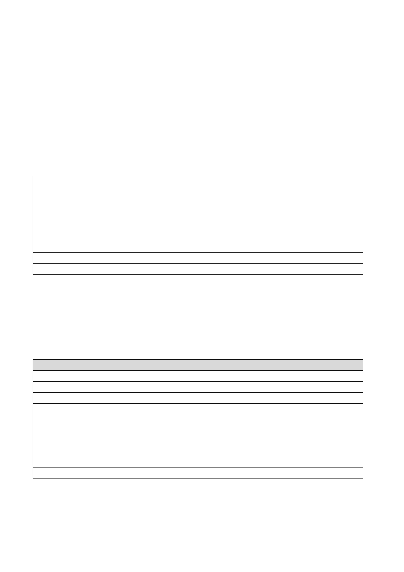
ATBM6162 module is a highly integrated 2.4&5GHz dual band, WiFi 4/5/6 (802.11 a/b/g/n/ac/ax), 20MHz and
40MHz bandwidth Wireless LAN (WLAN) device with USB 2.0 interface, based on AltoBeam’s ATBM6162 chip.
ATBM6162 supports Bluetooth LE v5.0, Long range (Coded PHY), and WiFi paring via BLE.
2 General specifications
Main chip AltoBeam ATBM6162
Host interface USB 2.0
RF antenna External 2.4&5GHz dual band antenna
Security WPA, WPA2, WPA3 personal
Power supply requirement 3.3VDC 600mA
Operating temperature
-40 ~ +85
℃
ambient temperature
Storage temperature
-50~ +125
℃ ambi ent temperature
Humidity 5% to 90% maximum (non-condensing)
Dimension Typical L13.00*W12.20*H1.90mm (±0.2mm)
3 RF specifications
3.1 2.4GHz WiFi specifications
General specification
Operating frequency 2412~2462MHz, 2422~2452MHz
Standard IEEE 802.11b/g/n/ax 1T1R
Modulation
DSSS, OFDM, OFDMA
Bandwidth
802.11b/g: ≤20MHz
802.11n/ax: ≤40MHz
PHY data rates
802.11b: 1, 2, 5.5, 11Mbps
802.11g: 6, 9, 12, 18, 24, 36, 48, 54Mbps
802.11n: MCS0~7, up to 150Mbps
802.11ax: MCS0~11, up to 286.8Mbps
Frequency offset
≤±10ppm
AltoBeam Inc. Confidential Document 2
3.2 5GHz WiFi specifications
General specification
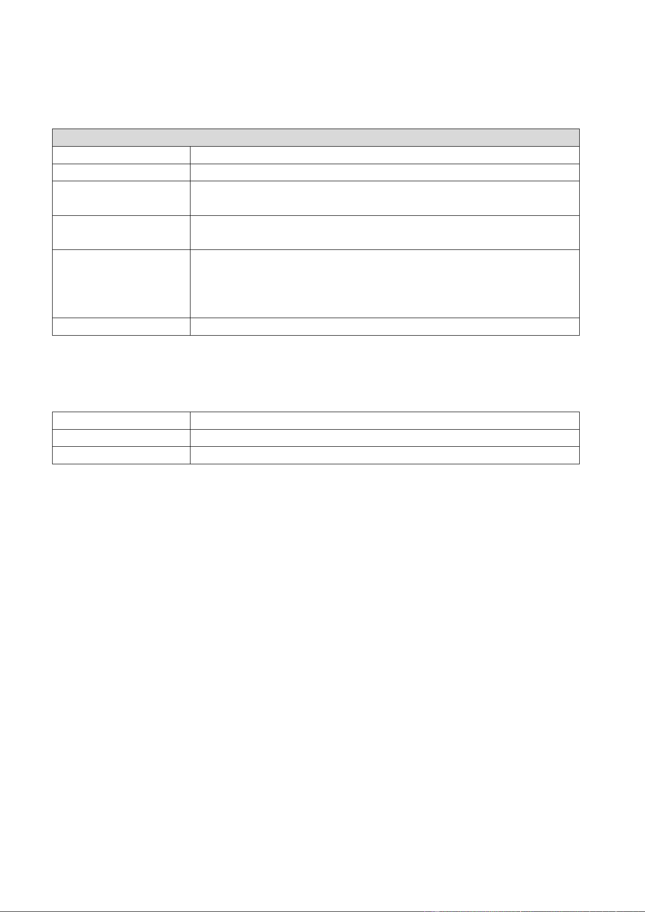
Operating frequency 5.15 ~ 5.25GHz; 5.25 ~ 5.35GHz; 5.47~5.725GHz; 5.725~5.850GHz
Standard IEEE 802.11a/n/ac/ax 1T1R
Modulation
802.11a/n/ac/ax (OFDM,
OFDMA): BPSK, QPSK, 16QAM, 64QAM, 256QAM,
1024QAM
Bandwidth
802.11a: ≤20MHz
802.11n/ac/ax: ≤40MHz
PHY data rates
802.11a: 6, 9, 12, 18, 24, 36, 48, 54Mbps
802.11n: MCS0~7, up to 150Mbps
802.11ac: MCS0~9, up to 200Mbps
802.11ax: MCS0~11, up to 286.8Mbps
Frequency offset ≤±10ppm
3.3 BLE RF specifications
Operating frequency 2.402 ~ 2.480GHz
Modulation GFSK
PHY data rates 1Mbps, 2Mbps
AltoBeam Inc. Confidential Document 3
4 Mechanical Specification
4.1 Outline drawing
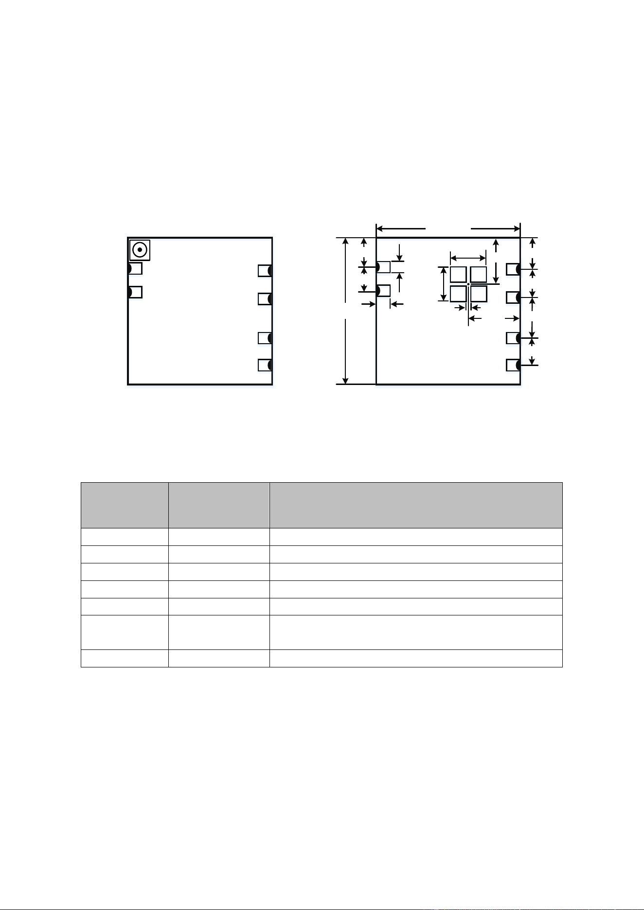
The typical module size of ATBM6162 module is L13.00*W12.20*H1.90mm (±0.2mm).
GND
ANT1
GND
U+
U-
3.3V
5
6
4
3
2
1
13.0±0.2
2.38
2.00
2.87
2.50
3.50
2.80
12.2±0.2
1.00
3.00
4.95
3.00
5.10
ANT2
1.00
0.20
Outline drawing (Top View)
4.2 Pin definition
Pin Number Pin Name Pin Description
1 3.3V 3.3V DC power supply input
2 U- USB Data DN
3 U+ USB Data DP
4 GND Ground
5 RF GND RF ground
6 ANT1 (NC)
NC as default. Connect to external 2.4&5GHz dual band
antenna for another model of module.
- ANT2 IPEX connector to external 2.4&5GHz dual band antenna
The module requires a stable DC 3.3V (±10%) input and can draw up to 600mA during peak operation. The
module includes an on-board voltage regulator, which ensures stable RF performance across the specified
input voltage range.

AltoBeam Inc. Confidential Document 4
5 WiFi Antenna
This module needs to connect with an external WiFi antenna supporting both 2.4GHz and 5GHz bands. The
microstrip line of PCB layout between the module’s antenna pin and IPEX antenna connector, the length of the
microstrip line is required to be less than 20mm, and it should be as straight as possible. If there must be a corner,
the angle is required to be greater than 120 degrees. The impedance of the microstrip line must be 50ohm for both
2.4GHz and 5GHz, and there is a complete reference ground plane under microstrip line. In order to optimize RF
performance, the ground under IPEX antenna connector needs to be removed.
6 FCC warning statement
Important Note
Any Changes or modifications not expressly approved by the party responsible for compliance could void the user’s
authority to operate the equipment.
This device complies with part 15 of the FCC Rules. Operation is subject to the following two conditions: (1) This device
may not cause harmful interference, and (2) this device must accept any interference received, including interference that
may cause undesired operation.
Note: This equipment has been tested and found to comply with the limits for a Class B digital device, pursuant to part 15
of the FCC Rules. These limits are designed to provide reasonable protection against harmful interference in a residential
installation. This equipment generates, uses and can radiate radio frequency energy and, if not installed and used in
accordance with the instructions, may cause harmful interference to radio communications. However, there is no
guarantee that interference will not occur in a particular installation. If this equipment does cause harmful interference to
radio or television reception, which can be determined by turning the equipment off and on, the user is encouraged to try
to correct the interference by one or more of the following measures: —Reorient or relocate the receiving antenna.
—Increase the separation between the equipment and receiver. —Connect the equipment into an outlet on a circuit
different from that to which the receiver is connected. —Consult the dealer or an experienced radio/TV technician for
help.
Radiation Exposure Statement
This equipment complies with FCC radiation exposure limits set forth for an uncontrolled environment. This
equipment should be installed and operated with minimum distance 20cm between the radiator& your body.

AltoBeam Inc. Confidential Document 5
7 Integration instructions for product manufacturers according to
KDB 996369 D03
7.1 List of applicable FCC rules
CFR 47 FCC PART 15 SUBPART C and SUBPART E has been investigated.
7.2 Specific operational use conditions
This module is certified for indoor use only, specifically for 5GHz operations in the 5150-5250 MHz and
5250-5350 MHz bands. The integrator must ensure that the host device does not operate these bands
outdoors.
7.3 Limited module procedures
The module does not have its own RF shield.
7.4 Trace antenna designs
Not applicable.
7.5 RF exposure considerations
To maintain compliance with FCC’s RF Exposure guidelines, this equipment should be installed and operated
with minimum distance of 20cm from your body, and must not be co-located or operating in conjunction with
any other antenna or transmitter. For distances less than 20 cm, SAR testing may be necessary depending on
the configuration.
7.6 Antennas
This radio transmitter FCC ID : 2BAVS-ATBM6162 has been approved by Federal Communications
Commission to operate with the antenna types listed below, with the maximum permissible gain indicated. The
antenna is permanently fixed. It cannot be replaced.

AltoBeam Inc. Confidential Document 6
No.
Antenna
Type
Frequency Range Antenna Gain
1
Dipole
antenna
BLE 1M/2M: 2402-2480MHz:
3.17dBi
2.4G WiFi: 2412 -2462MHz, 2422~2452MHz: 3.17dBi
5150-5250MHz: 2.34dBi; 5250-5350MHz: 2.66dBi
5470-5725MHz: 2.39dBi; 5725-5850MHz: 2.57dBi
7.7 Label and compliance information
The product must be labeled in a visible area with the following "Contains FCC ID: 2BAVS-ATBM6162”
7.8 Host Integration Test Plan:
To ensure the final product remains compliant, the integrator must verify, at a minimum, the following parameters during the
initial host evaluation or when seeking a C2PC. If any parameter fails to comply, the host design must be corrected, and the
grantee must be contacted.
Test Item Test Conditions and Guidance Limit
Conducted Output Power
Measure the maximum power at the
module antenna port
Shall not exceed the power recorded in
the original module grant by more than
± 0.5dB.
Radiated Spurious Emissions
Focus on non-harmonic and harmonic
spurious from 30 MHz to 25 GHz at the
worst case mode
Must comply with limits in CFR 47 Part
15.247 / 15.209 / 15.407.
Band-Edge Compliance
Measure radiated power at the lower
and upper band edges at the lowest
and highest operating channels.
Must comply with limits in CFR 47 Part
15.247 / 15.209 / 15.407.
Note: All tests shall be performed in accordance with the applicable measurement procedures of ANSI C63.10-2020.
7.9Additional testing, Part 15 Subpart B disclaimer
Module manufacturer is responsible for compliance of the system with module installed with all other applicable
requirements for the system such as Part 15 Subpart B.

AltoBeam Inc. Confidential Document 7
7.10 C2PC Responsibility Statement
The grantee, AltoBeam Inc., is solely responsible for filing a Class II Permissive Change (C2PC) application for
all new host configurations. The integrator must coordinate with AltoBeam before implementing any such
changes.
Grantee (AltoBeam Inc.) contact information
Tel: +86 -10-62701811
E-mail: [email protected]
om
Nan Li