
1
Be Honest & Do Best
ARM-based Industrial Computer
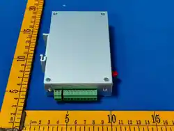
USR-EG228
Edge + Node-RED + Ubuntu OS
Edge computing, network management
built-in configuration, Diverse I/O Interface
Rich protocols, simple configuration
Your Trustworthy Smart Industrial IoT Partner

2
Directory
1. Product Introduction ........................................................................................................................
3
2.Product Feature ................................................................................................................................
33.Functional Framework ......................................................................................................................
44.Application Guidance .......................................................................................................................
5
4.1.Web page configuration .........................................................................................................5
4.2.Network management ............................................................................................................6
4.2.1.Network switching ........................................................................................................ 7
4.2.2.Cellular network ............................................................................................................9
4.2.3.Ethernet ...................................................................................................................... 13
4.2.4.Route ...........................................................................................................................16
4.2.5.VPN ............................................................................................................................. 18
4.2.6.Network diagnosis ...................................................................................................... 22
4.2.7.Firewall ....................................................................................................................... 22
4.4.Edge computing ................................................................................................................... 23
4.4.1.Serial port management .............................................................................................24
4.4.2.Data point table ..........................................................................................................25
4.4.3.Edge acquisition ......................................................................................................... 31
4.4.4.Edge computing ..........................................................................................................32
4.4.5.Actively report .............................................................................................................34
4.4.6.Protocol conversion .................................................................................................... 39
4.4.7.Linkage control ........................................................................................................... 42
4.5.Node-Red ..............................................................................................................................45

3
1.Product Introduction
WukongEdge one-stop integrated edge application architecture, with data processing as the
core, integrates edge computing, configuration management, PLC programming, network
management and other functions, providing comprehensive support for industrial control and IoT
industries. The application is simple to use, widely applicable, and can seamlessly interface with
the existing system architecture of various industries, bringing efficient and intelligent one-stop
comprehensive application services to the industrial control and Internet of Things industries
The USR-EG228 is a Linux industrial computer with an outstanding cost-performance ratio. It is
equipped with an industrial-grade RK3506J three-core Cortex-A7 processor with a main frequency
of 1.2 GHz and an embedded WukongEdge edge computing engine. With simple configuration, it
can complete data collection, edge computing and cloud reporting. It comes pre-installed with the
latest Node-Red, featuring drag-and-drop programming, allowing business logic to be
implemented immediately. It has strong communication capabilities: 4G and Ethernet, with
different network combinations to meet more demands. It is also equipped with 1×USB, 2×RS485,
and 2×CAN, making it easy to connect to various industrial sites. The system is based on a Linux
Ubuntu environment, with open root access and a one-click setup for the development
environment, allowing creativity to flow freely and projects to go live quickly.
.
2.Product Feature
Comprehensive functions: data processing as the core, integrated edge acquisition,
calculation, reporting, protocol conversion, linkage control, network management, IO
management, configuration management, PLC programming and many other functions.
Rich collection: Support various PLC protocols, as well as industry-specific protocols such as
power, water conservancy, building, electricity meter, etc., such as 104, 61850, SL651, Bacnet,
DL/T645, etc.
Flexible reporting: Active reporting methods such as change reporting, scheduled reporting,
periodic reporting and custom JSON are provided.
Link diversity: Support multi-link, including MQTT, TCP, HTTP, TLS/SSL and other multi-link
transmission protocols.
Convenient networking: support 4G networking methods, combine with Ethernet to
4
achieve dual-network backup. It comes with routing, VPN, firewall, network diagnosis
functions, and can be combined with the cloud to achieve remote networking in different
locations.
Flexible configuration: local operation is convenient, no complex network configuration is
required; with multi-configuration design, real-time control of data, the screen can be
customized independently.
Convenient remote management: With cloud access function, remote management can be
realized through cloud.
Flexible development: Runs on Linux Ubuntu 22.04 system, supporting development and
design in multiple languages such as C, C#, C++.
3.Functional Framework
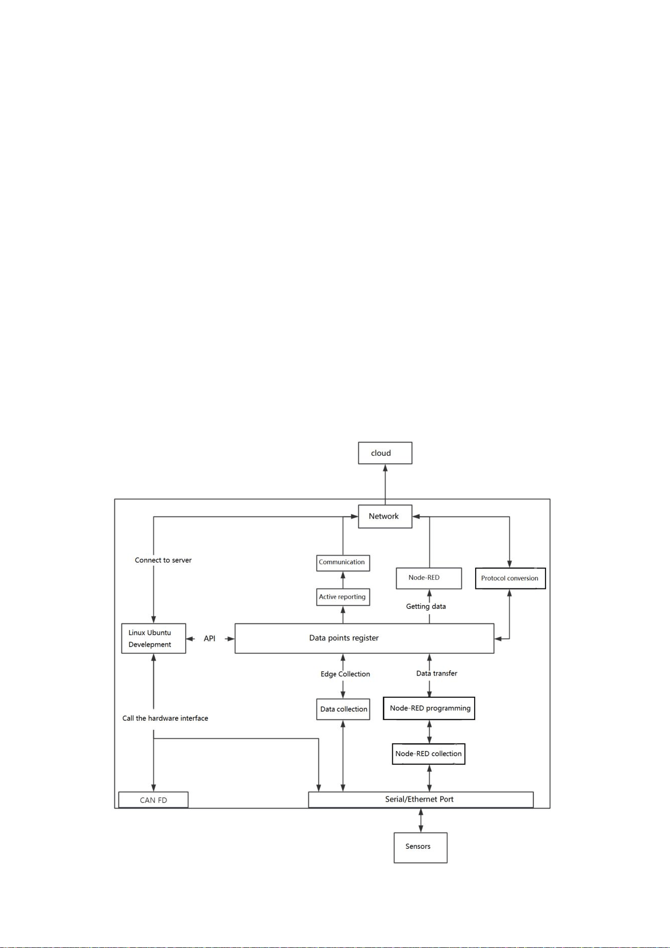
The WukongEdge application is embedded within the EG228 product. As the largest
application apart from the Linux secondary development, its functional operation structure is as
follows:

5
WukongEdge application framework integrates five core modules: edge acquisition,
configuration management, PLC programming, network management and general functions. Each
module communicates efficiently through its own API and cooperates with each other to form an
organic whole. It is with this close collaboration mechanism that WukongEdge edge applications
can achieve comprehensive processing of multi-source data, ensuring stable and efficient
operation of the system and meeting the diverse needs of complex industrial scenarios and IoT
applications.
In addition to the above five core modules, WukongEdge is uniquely integrated into the built-in
web features. The web page integrates all parameter configuration options of the five functional
modules, so users do not need to switch and search in different interfaces or tools. On this unified
web page platform, all kinds of parameter settings can be completed in one stop, which is simple
and convenient to operate, greatly improving the user's work efficiency and experience.
• Secondary Development
1. By using serial port and network port, sensor data is actively collected and sent to the Linux
secondary application through API interface for complex data processing. After processing, the
data can be returned to the data point table through API for reporting and configuration display.
2. By using serial port and network port, sensor data is actively collected and sent to the Linux
secondary application for complex data processing. Through secondary development, server
protocol connection is achieved, and the data is directly reported to the server.
3. By directly accessing the hardware interface in Linux, the desired data is obtained and
directly connected to the server for data collection, processing and reporting, without going
through the WukongEdge engine.
4.Application Guidance
This section provides an in-depth and comprehensive introduction to the WukongEdge app's
features, along with detailed app how-to guides for each feature to help you quickly master and
use them.
4.1.Web page configuration
WukongEdge's web configuration system is designed with extreme convenience as its core
concept, simplifying complexity and eliminating redundant steps. Users do not need complex
operation process, only need to click and set on the intuitive web interface, you can quickly
complete various configurations, greatly shorten the time cycle from deployment to actual
application, help users integrate WukongEdge into business processes faster, and efficiently
6
achieve the expected application goals.
Operation steps:
After the device is powered on, connect the computer and hardware devices through the LAN
port, and WukongEdge's built-in routing will assign IP addresses to the computer.
Open "192.168.1.1" through the computer browser, enter the login interface, enter the default
user name and password interface to enter. The default username and password is
admin/admin.
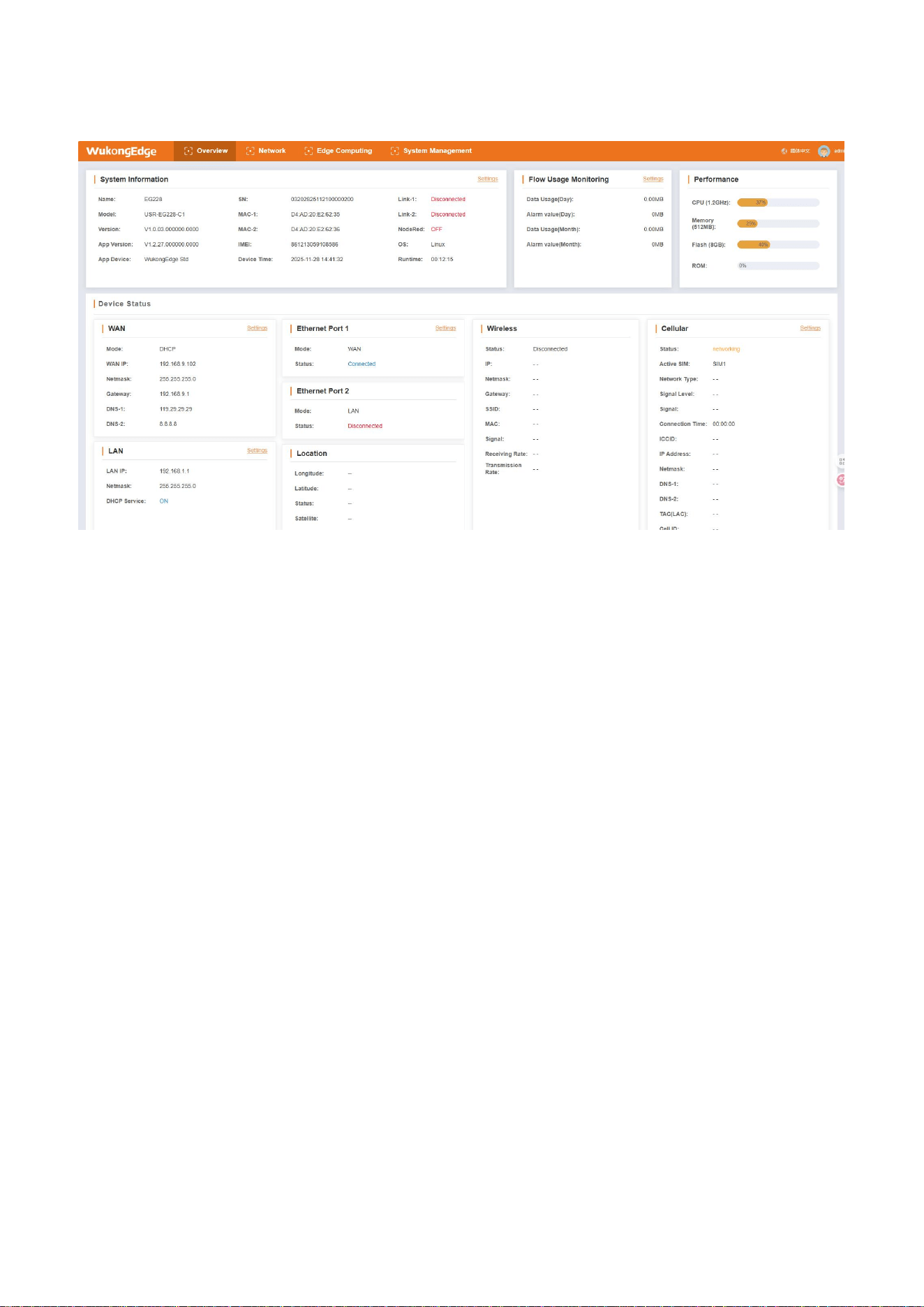
After entering, the overview interface will be displayed first, which will show the status of
WukongEdge's network and important information of the device.
4.2.Network management
The WukongEdge app is fully integrated in terms of network functionality, providing users with
the ultimate in network flexibility and stability.
More importantly, its integrated routing, VPN and firewall functions build a strict network
security protection system. Routing function ensures efficient data transmission, VPN helps users to
establish Private Cloud connection safely in public network, firewall monitors network traffic in real
time, resists all kinds of potential network attacks, and comprehensively protects users 'network
security
Cellular network, Ethernet access methods are available to meet the network
connection needs of different scenarios. Whether you rely on cellular networks to maintain data
communication in mobile work environments or high-speed and stable network access via
Ethernet in fixed locations, it is easy to achieve.
.
7
Not only that, WukongEdge app is also equipped with powerful network diagnostics, support
for multi-network backup and multi-link Internet access. When the primary network fails, the
system can automatically switch to the backup network link to ensure continuous stability of the
network connection. At the same time, the network diagnosis function can monitor the network
status in real time, quickly locate the fault point, greatly improve the network operation and
maintenance efficiency, and provide a solid guarantee for the service continuity of users.
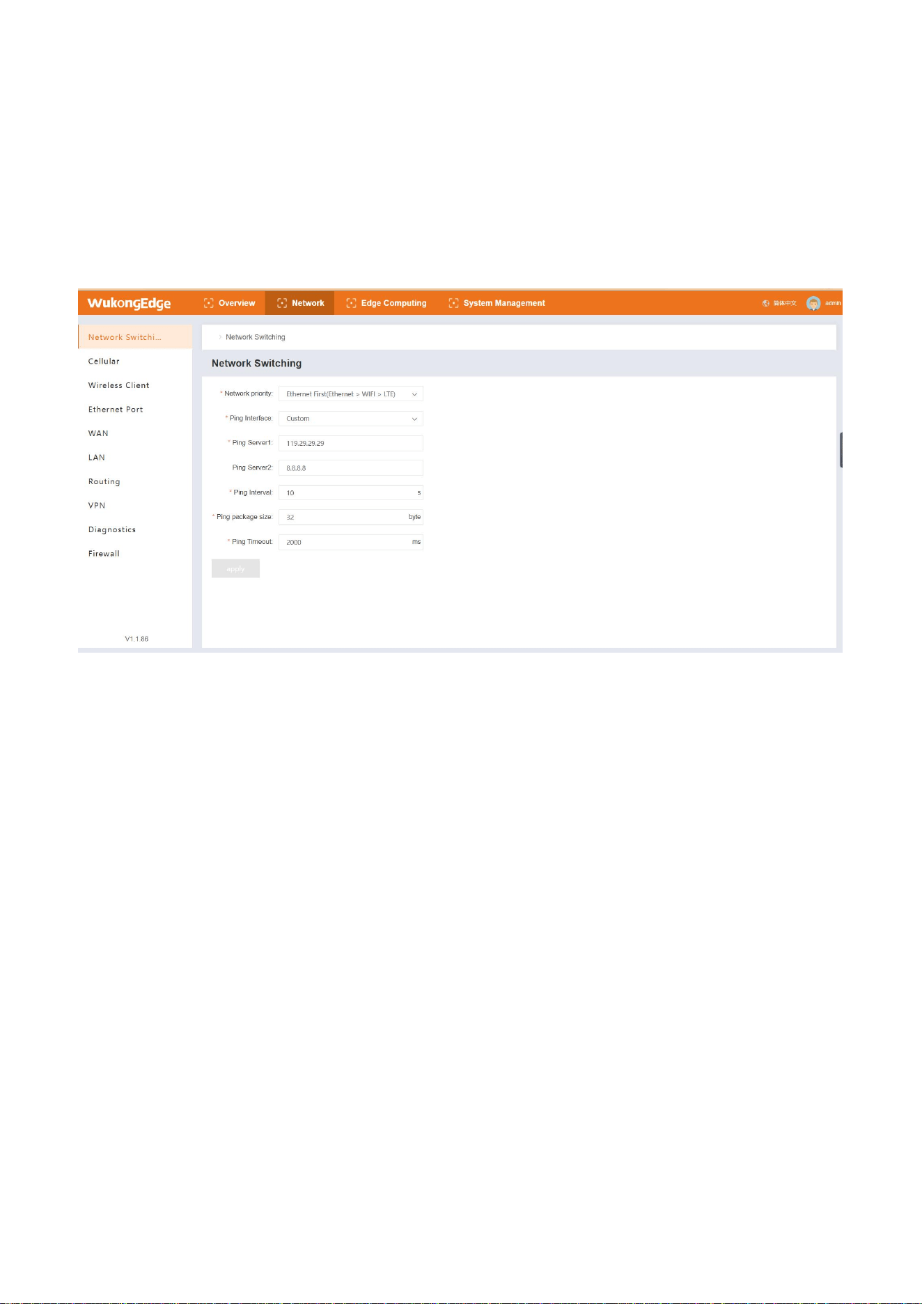
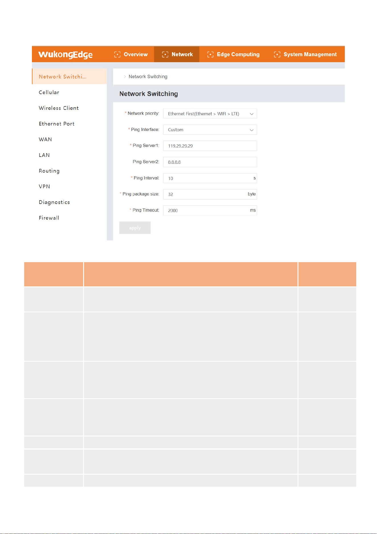
4.2.1.Network switching
The network switching function is mainly used to set the priority order of network use in
multi-network mode. With this feature, the higher priority networks are enabled first. Once a high
priority network is disconnected, the system will automatically switch to a lower priority network
according to the preset order, so as to ensure the stability and continuity of the network
connection.
8
Parameter introduction:
Name
Parametric description
Default
parameters
Network priority
Priority network, automatic switch to alternate network when
priority network cannot be connected
Ethernet first
Detection mode
Custom: Determine network status based on custom probe
addresses
Gateway: Probes WAN gateway addresses to determine network
status
Custom
Probe Address 1
When the probe mode is customized, ping this address for
communication probe is preferred. If there is a reply, the network
is normal. If there is no communication, the probe fails.
119.29.29.29
Probe Address 2
When the probe mode is customized, when the probe address 1
fails to detect, the ping operation will be performed using
address 2. Ping generally means that the network is normal.
8.8.8.8
Sounding period
Set link detection interval: 1-600s can be set
10s
Ping packet size
ping packet data size when detecting link: 32-1024 bytes can be
set
32 bytes
Ping timeout
Ping timeout time: 100-20000ms can be set
2000ms

9
4.2.2.Cellular network
4G support: WukongEdge can support 4G networks, which enables it to use high-speed mobile
networks for data transmission and other operations, providing users with faster data transmission
speeds and lower latency to meet the network performance requirements in different scenarios.
Automatic identification: With network detection and signal detection mode, it can
automatically identify the currently available network type and signal strength. This allows the
device to make intelligent decisions based on the actual situation of the network, such as
automatically trying to switch to the 3G network when the signal of the 4G network is not good.
Automatic handover: With automatic handover function, WukongEdge can seamlessly switch
between different networks or between different signal sources of the same network to ensure
stable connection of cellular network, reduce connection interruption caused by network signal
10
fluctuation or failure, and improve user's network experience.
This design and functional features enable WukongEdge to have high flexibility, stability and
adaptability in cellular network connectivity, and can better meet the network requirements of
various application scenarios.
Note: Only available for 4G version.
Application Configuration:
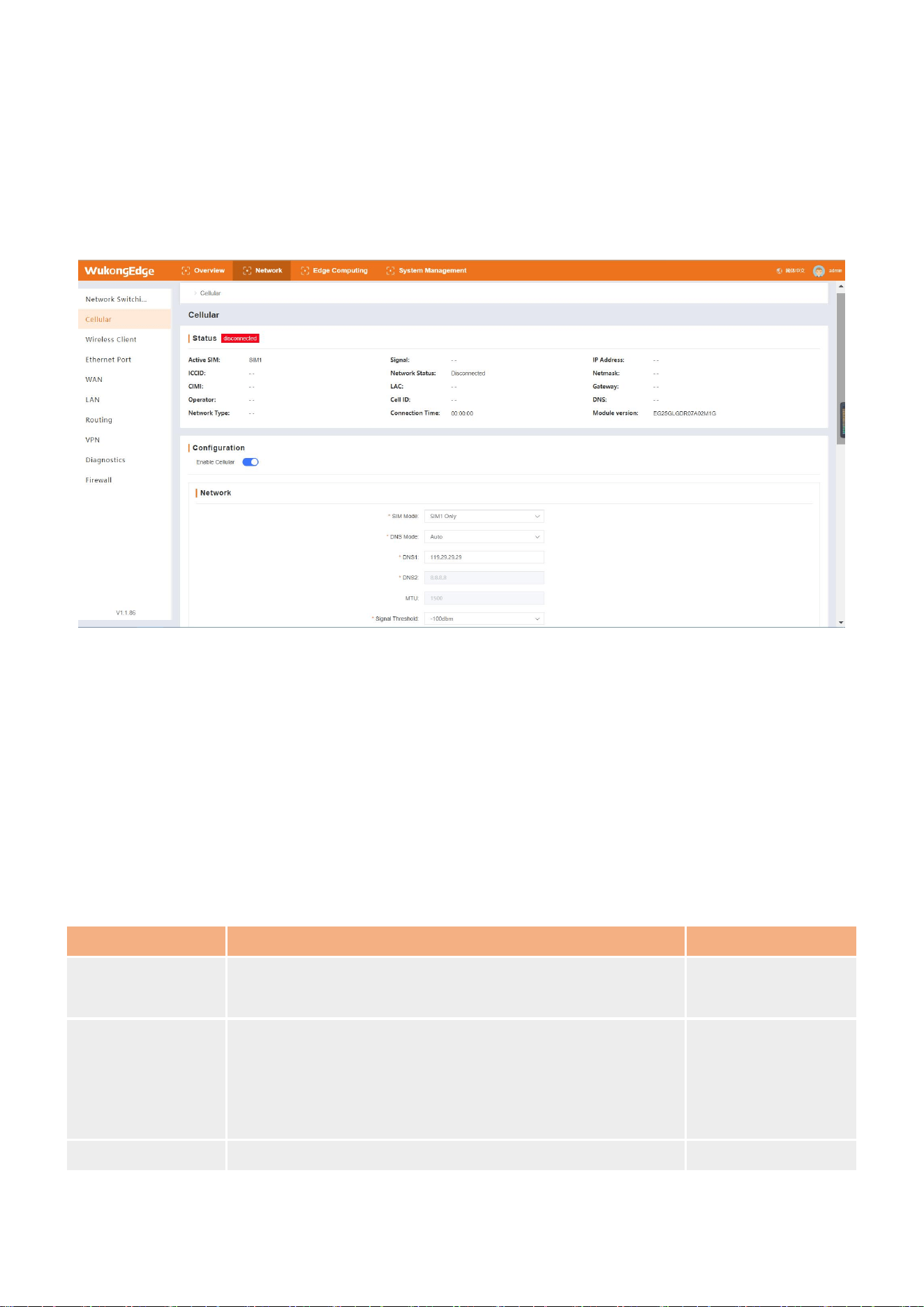
Go to the built-in web page, find "Network-> Cellular Network", and turn on cellular network.
Configure dual card mode and configure detection;
Configure parameters such as APN of SIM1 and SIM2. If single card mode is selected, only the
selected SIM card needs to be configured.
After the configuration is completed, click the "Apply" button to complete the configuration,
and it will take effect immediately after application.
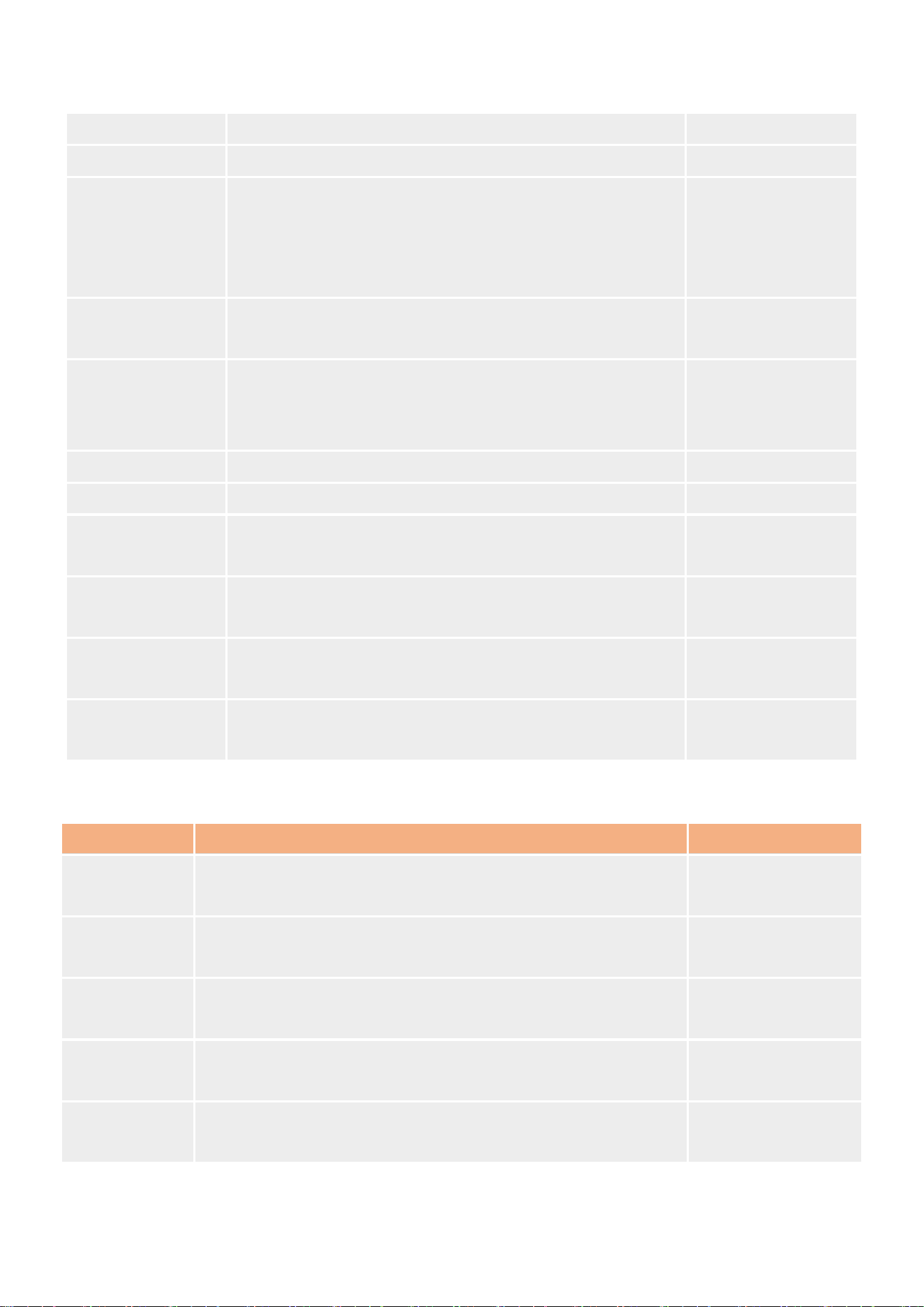
Parameter introduction:
Name
Parametric description
Default parameters
Dual SIM mode
First dial with priority SIM card, four modes supported,
SIM1 only and SIM2 only for single card mode
SIM1 priority
DNS acquisition
Method
Automatic acquisition: automatically acquire DNS server
address from base station
Manual setting: manually set the address of DNS
resolution server
automatic
acquisition
DNS1
DNS server IP can be set
119.29.29.29
11
DNS2
DNS server IP can be set
8.8.8.8
MTU
Maximum transmission unit, in bytes, range 128~1500
1500
Signal threshold
if that average value of the current SIM signal detect
within a certain period of time is less than a set
threshold, switching to another card for network
connection
-100dbm
Signal query
interval
The interval time between two signal queries of the
current SIM, ranging from 1 to 3600
60s
Maximum number
of dialling
When the priority SIM fails to dial successfully within the
set maximum number of times, the device will switch to
another SIM for dialing.
3
Link probing
Ping to check if the link is open
SIM1&SIM2
Probing interval
Ping interval, range: 5~86400s
10s
Detection times
Continuous failure peak, redial after reaching this
number, range 1~100
4
Detection timeout
The maximum time for a single probe to wait for a reply.
If no reply occurs after timeout, the probe will fail.
5s
Probe Address 1
Ping address 1. If you can ping this address, the network
is unblocked.
119.29.29.29
Probe Address 2
Ping address 2. If you can ping this address, the network
is unblocked.
8.8.8.8
SIM card setting parameters are as follows:
Name
Parametric description
Default parameters
APN
Used to identify the service type of WCDMA/LTE network,
ranging from 0 to 62 characters
empty
User name
Specifies the user name of the user accessing the external
PDN network, ranging from 0 to 62 characters
empty
Password
Specifies the password of the user accessing the external
PDN network, ranging from 0 to 62 characters
empty
Authentication
mode
Authentication mode: NONE,PAP,CHAP,PAP CHAP
NONE
Type of
network
Auto, 4G, 3G and 2G networks supported
Auto

12
PIN Code
PIN code is the personal identification code of SIM card. After
it is enabled, it is necessary to set correct PIN code to dial
normally. PIN code range is 4~8 characters.
close
Network mode Auto, 4G, 3G and 2G networks supported Auto

13
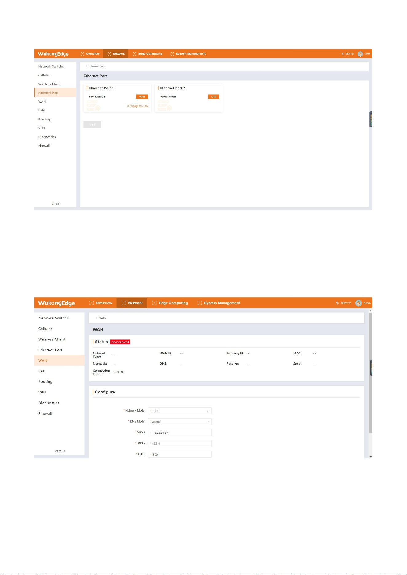
The default port 1 is WAN port, which can be switched to LAN port.
In the built-in web page, switch in the "Network-> Gateway Management" interface. After
switching, click the application, and there will be a restart pop-up window. This function needs to
be restarted to take effect. (The function switching of hardware network port needs to be
4.2.3.Ethernet
Ethernet management covers network port mode management, WAN port configuration
management and LAN port management. Due to different hardware adaptation, the interface
adaptation is flexible, and the network port mode can realize WAN and LAN mode switching. WAN
interface is responsible for connecting external networks, such as Internet service providers, to
ensure that equipment access to the wide area network, to achieve external data transmission and
reception. LAN port is used to build a local local area network, which facilitates the interconnection
of internal devices, such as computers and printers, and realizes the rapid sharing and exchange
of data. Under WukongEdge management, WAN and LAN work together to meet the needs of
different network application scenarios.
4.2.3.1.Network port mode switching:
reinitialized to ensure normal network port communication).
14
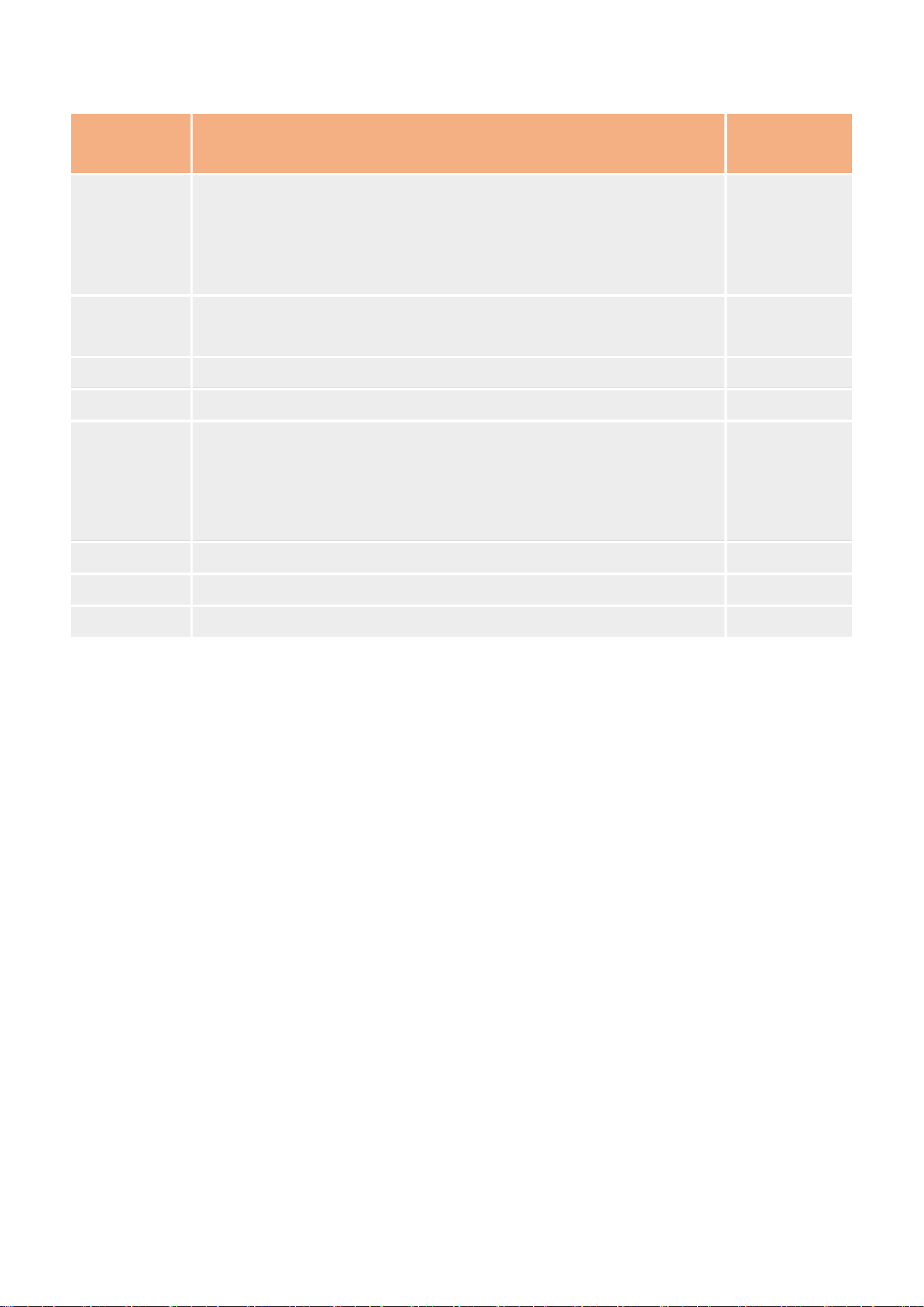
WAN port management built-in interface is divided into status management and parameter
configuration. The former displays key information such as connection status and IP address, while
the latter is used to set the way to obtain IP address and address configuration. Once the
parameters are set, click Apply and it will take effect immediately
4.2.3.2. WAN port management
.
Parameter Description:
15
Name Parametric description
Default
parameters
Network
mode
DHCP (Dynamic IP): WAN as DHCP client, using DHCP to obtain IP
address and subnet mask information
Static IP: Manually configure information such as IP addresses and
subnet masks for Ethernet interfaces
DHCP
Static
address
In Static IP mode, manually configure the IP address of the device
for network identification of the device
192.168.0.7
Subnet mask WAN subnet range in Static IP mode 255.255.255.0
Gateway WAN gateway address in Static IP mode 192.168.0.1
DNS
acquisition
method
Automatic configuration: automatically obtain DNS resolution
server address from public network
Manual configuration: Manually set DNS server address for local
area network communication
manual
configuration
DNS1 DNS server IP can be set 119.29.29.29
DNS2 DNS server IP can be set 8.8.8.8
MTU Maximum transmission unit, in bytes, range 128~1500 1500
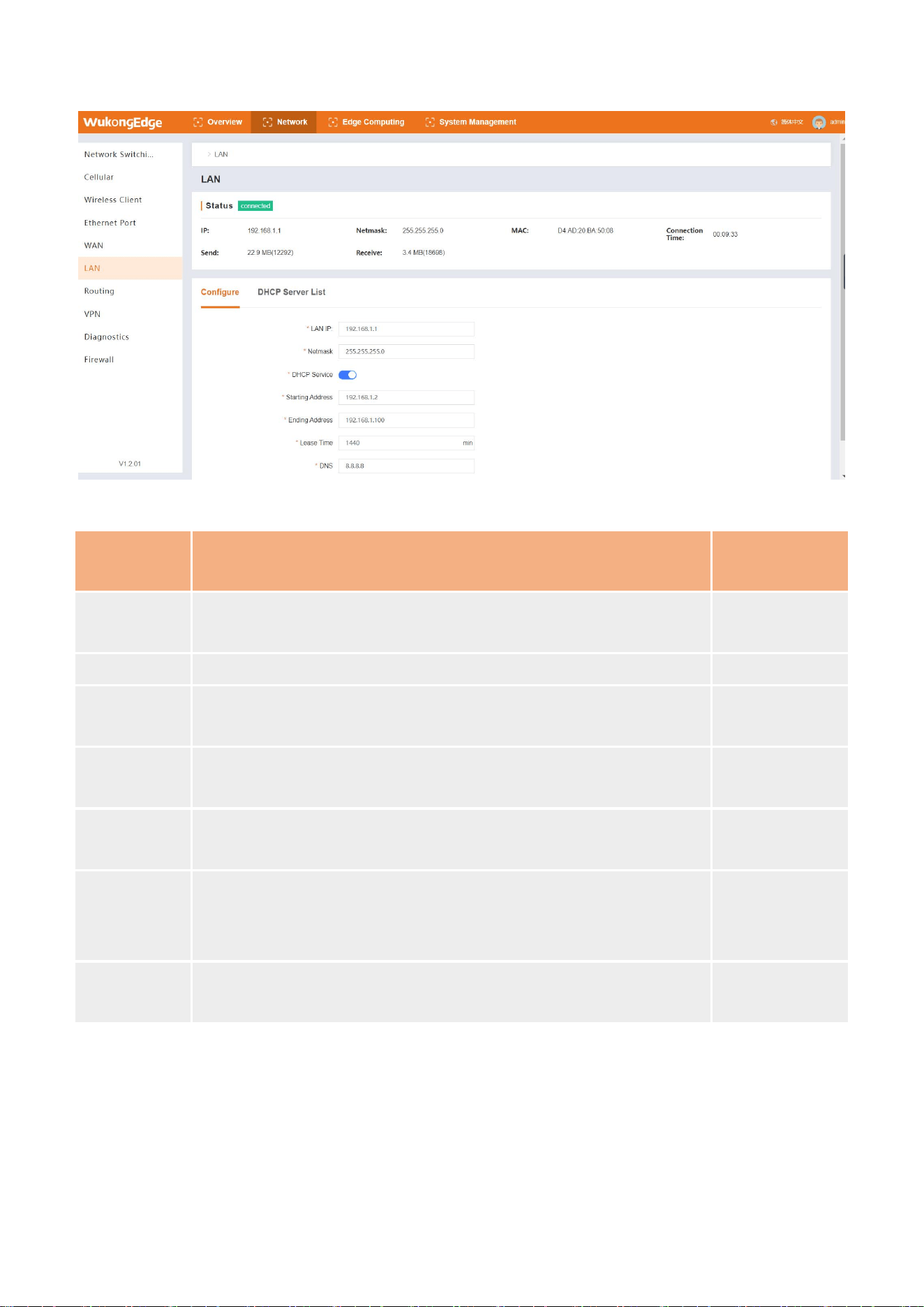
LAN port management covers three parts: status display, parameter configuration and DHCP
server. Status display presents real-time status; parameter configuration can set relevant
parameters as needed;DHCP server allocates IP for lower end devices and displays them in a list,
and can also match fixed IP for fixed MAC address devices through static address allocation. All
LAN port configurations are effective immediately after application
4.2.3.3. LAN port management:
.
16
Parameter Description:
Name Parametric description
Default
parameters
LAN IP
LAN IP address, which can be used as gateway of LAN port to
access local area network formed by client
192.168.1.1
Subnet mask LAN subnet range 255.255.255.0
DHCP
service
The function of assigning addresses to connected clients through
the LAN port is enabled by default and can be disabled.
open
Initial
address
Sets the starting IP address assigned to the client device in the
address pool
192.168.1.2
End address
Sets the end IP address assigned to the client device in the
address pool
192.168.1.100
Period of
validity
Set the validity period of the assigned IP address. DHCP server
will reclaim the IP address assigned to the client and reallocate
the IP address after the expiration date. Cannot be empty.
1440min
DNS server
address
LAN port client domain name resolution server address, changed
to gateway, default to WAN port proxy DNS
8.8.8.8
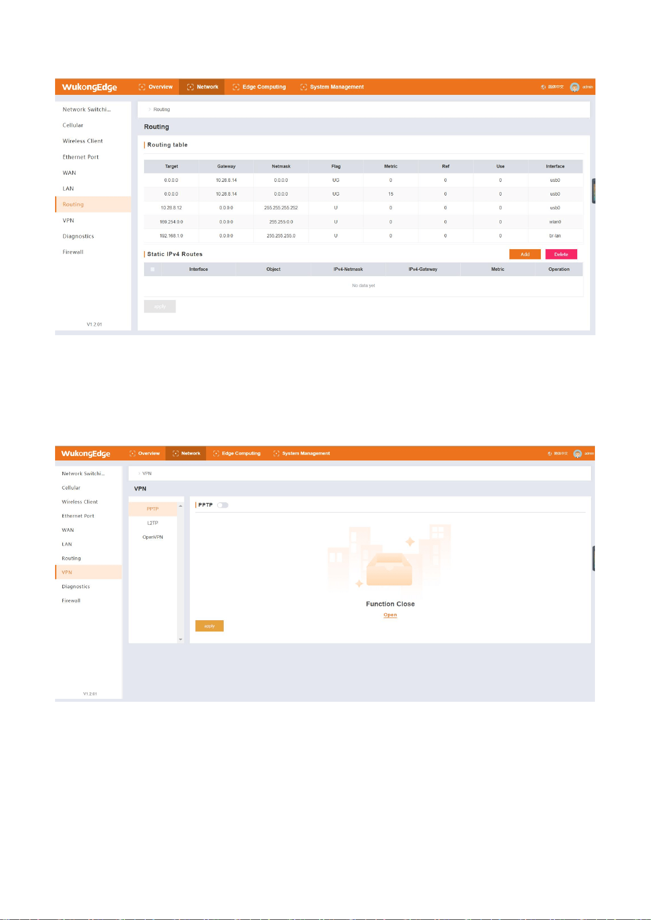
Static routing is a key feature of routing function. It is easy to operate. Users do not need
complex professional knowledge. They only need to fill in basic information such as destination
network address, subnet mask and next hop address on the built-in web page of the devic
4.2.4.Route
e
17
according to their own network requirements, and then they can easily complete configuration and
put into use.
Parameter Description:
Name
Parametric description
Default
parameters
port
The interface used by the destination network for data to
arrive
empty
target network
Destination IP address to reach
empty
IPv4 subnet
mask
Subnet mask of destination address to be reached
empty
IPv4 gateway
The IP address of the next router through which data
needs to pass before reaching its destination
empty
hop count
That is, priority, the smaller the value, the higher the
priority, ranging from 0 to 255
0
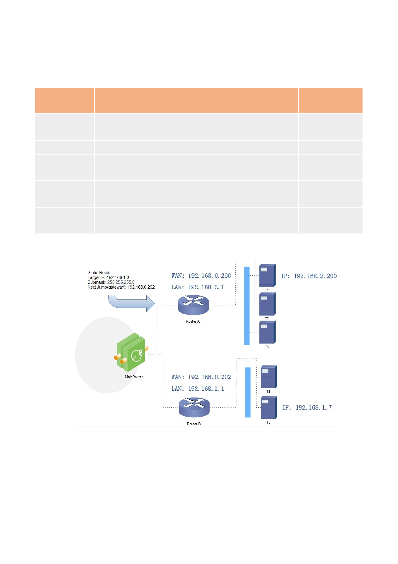
A static route can be illustrated by the following example:
Routers A and B both have WAN ports connected to the 192.168.0.0 network, router A has LAN
ports on the 192.168.2.0 subnet, and router B has LAN ports on the 192.168.1.0 subnet. Now, if we
want to make a route on router A that allows us to access the 192.168.1.x address, it will
automatically be transferred to router B. Because it is to be forwarded to all 192.168.1.x segments,
when adding routes, the subnet mask is set to 255.255.255.0. If the destination IP is set to a fixed IP
address, such as 192.168.1.7, the subnet mask is set to 255.255.255.255.
18
VPN functions play a key role in networking scenarios, supporting PPTP, L2TP and OpenVPN.
Each protocol has its own advantages and meets the diverse networking needs of different users
for network security, stability and compatibility
4.2.5.VPN
.
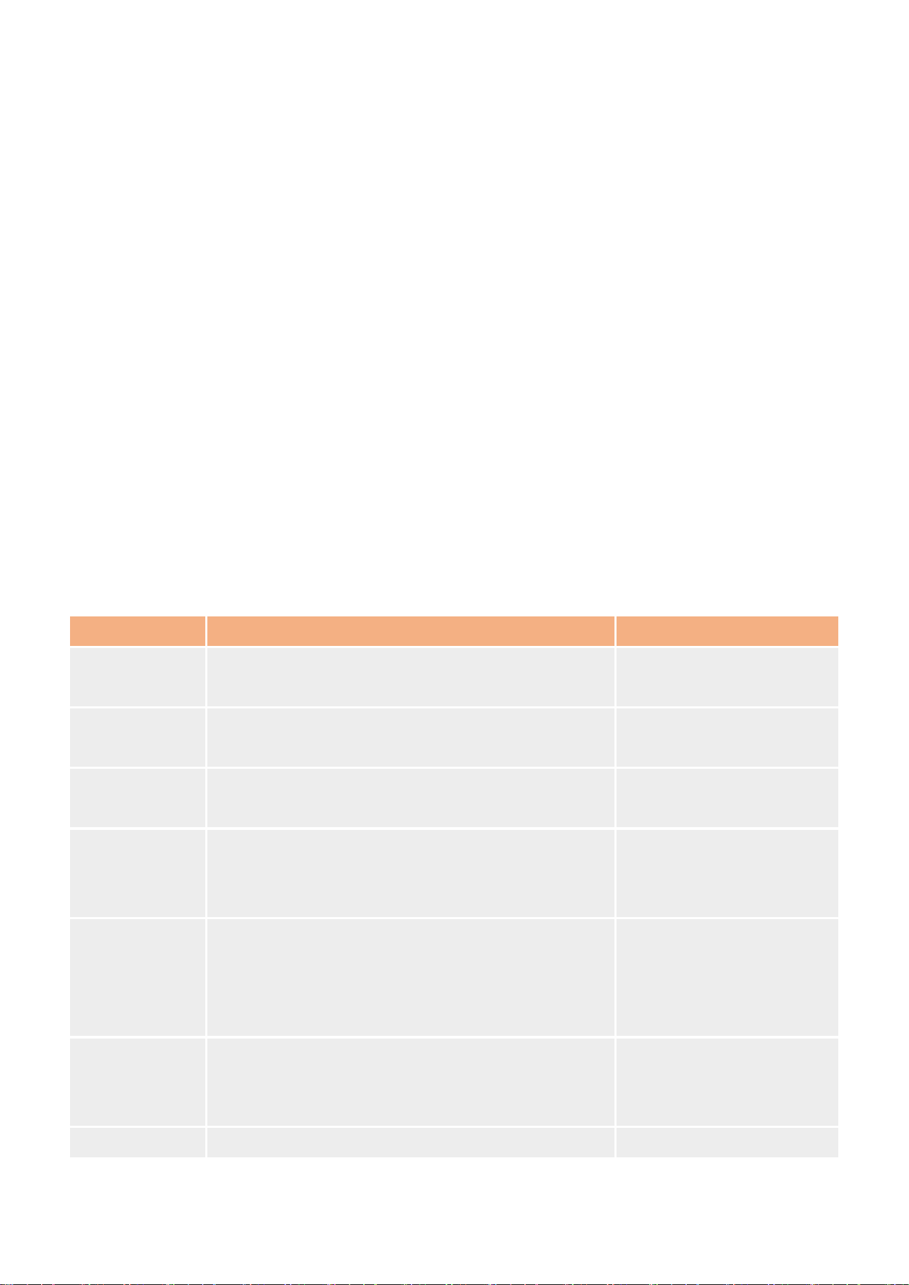
Operation steps:
Enter the built-in web page, find the "Network->VPN" interface, and select the corresponding
VPN Connections mode.
For example, select PPTP, then select PPTP, enter PPTP parameter interface, first align to
enable.
19
After enabling, the status information bar and parameter configuration will appear. Fill in the
corresponding parameters to be configured, and then click the "Apply" button.
After application, it will take effect immediately. Check the connection status in the status bar
and display the corresponding connection information to prove that the VPN connection has
been successful.
PPTP as a point-to-point tunneling protocol, with a TCP (port 1723) connection to maintain the
tunnel, using generic routing encapsulation (GRE) technology to encapsulate data into PPP data
frames, through the tunnel transmission, and can encapsulate PPP frame payload data encryption
or compression, like MPPE with MS-CHAP V2 authentication generated encryption key encryption
PPP frame
4.2.5.1.PPTP Client
.
Before use, you need to obtain the VPN server address, username, password and encryption
method, etc. After enabling the PPTP client function, accurately fill in these parameters. After the
VPN is in effect, you can view its status in the status information.
Parameter Description:
name parametric description default parameters
server address
Enter the VPN server IP or domain name to connect
to
192.168.0.2
port
Automatic, WAN and LTE 4G are available
depending on the networking mode.
voluntarily
username/pass
word
Get this information from the VPN server, limit it to
1 - 50 characters
username/password
terminal net
mask
If the NAT function is enabled, the subnet inter
working function under VPN can be directly
realized.
192.168.55.0/255.255.25.0
NAT
Replace internal addresses with public addresses
when content needs to communicate externally. If
this item is turned off, the network address
translation function cannot be realized.
close
MPPE
encryption
Data between the parties can be encrypted and
decrypted to prevent unauthorized access and
alteration.
close
MTU Maximum transmission unit, in bytes, range 1500
20
128~1500, same as VPN server
additional
configuration
PPPD parameters, magic words, etc. are added. By
default, no operation is required. 0~500 characters
empty
Static Tunnel IP
Address
Server side automatically assigns IP, you can fill in
static tunnel IP here
close
Ping to check
Real-time VPN online detection and reconnection
mechanism. Ensure stable connection by means of
cyclic ping custom IP. Not enabled by default
close
L2TP is a Layer 2 tunneling protocol, similar to PPTP. In the M300 device, it supports
multi-element authentication methods such as tunnel password authentication and CHAP, and the
encryption method adopts pre-shared key encryption of L2TP OVER IPSec. Users only need to enter
the "network"-"VPN"-"L2TP" path, fill in the corresponding settings, wait for VPN to take effect, you
can view the VPN status in the status information section.
Parameter Description
4.2.5.2. L2TP Client
:
name parametric description default parameters
server address
Enter the VPN server IP or domain name to
connect to
192.168.0.2
port
Automatic, WAN and LTE 4G are available
depending on the networking mode.
voluntarily
username/password
Get this information from the VPN server, limit it
to 1 - 50 characters
username/password
Tunnel
name/password
Fill in correctly after obtaining from VPN server empty
terminal net mask
If the NAT function is enabled, the subnet
interworking function under VPN can be directly
realized.
192.168.55.0/255.255.25.0
NAT
Replace internal addresses with public addresses
when content needs to communicate externally.
If this item is turned off, the network address
translation function cannot be realized.
close
MTU
Maximum transmission unit, in bytes, range
128~1500, same as VPN server
1500
additional PPPD parameters, magic words, etc. are added. empty
21
configuration By default, no operation is required. 0~500
characters
Static Tunnel IP
Address
Server side automatically assigns IP, you can fill
in static tunnel IP here
close
Ping to check
Real-time VPN online detection and reconnection
mechanism. Ensure stable connection by means
of cyclic ping custom IP. Not enabled by default
close
OpenVPN is an application-layer VPN solution based on OpenSSL library, which innovatively
integrates virtual network card and SSL protocol. This unique design not only easily achieves
networking goals, but also greatly improves connection security through the encryption features of
SSL protocol, and the operation process is extremely simple, easy for users to use, and highly
practical
4.2.5.3. OpenVPN
.
Parameter Description:
name parametric description
default
parameters
channel
protocol
TCP,UDP UDP
Remote host
IP address
OpenVPN Server IP/Domain Name 192.168.1.102
port OpenVPN server listening port 1194
authentication
type
NONE, username/password, pre-shared key, SSL/TLS, SSL/TLS+
username/password
topology Subnet, Point-to-Point, Net30 subnet
port
Network port, 4G, automatic according to different networking
methods
voluntarily
redirect
gateway
PPPD parameters, magic words, etc. are added. By default, no
operation is required. 0~500 characters
empty
NTA
This function is enabled by default. Replace internal addresses with
public addresses when content needs to communicate externally. If
this item is turned off, the network address translation function
cannot be realized.
open
Keepalive On by default. You need to set the detection interval and timeout. open
LZO Enable or disable data transfer using LZO compression self-adaption
22
encryption
algorithm
None/Blowfish-128/DES-EDE/DES-EDE3/AES-128/AES-192/AES-256 Blowfish-128
Hash
algorithm
None/SHA1/SHA256/SHA512/MD5 SHA1
TLS Method tls-auth/tls-crypt/OFF OFF
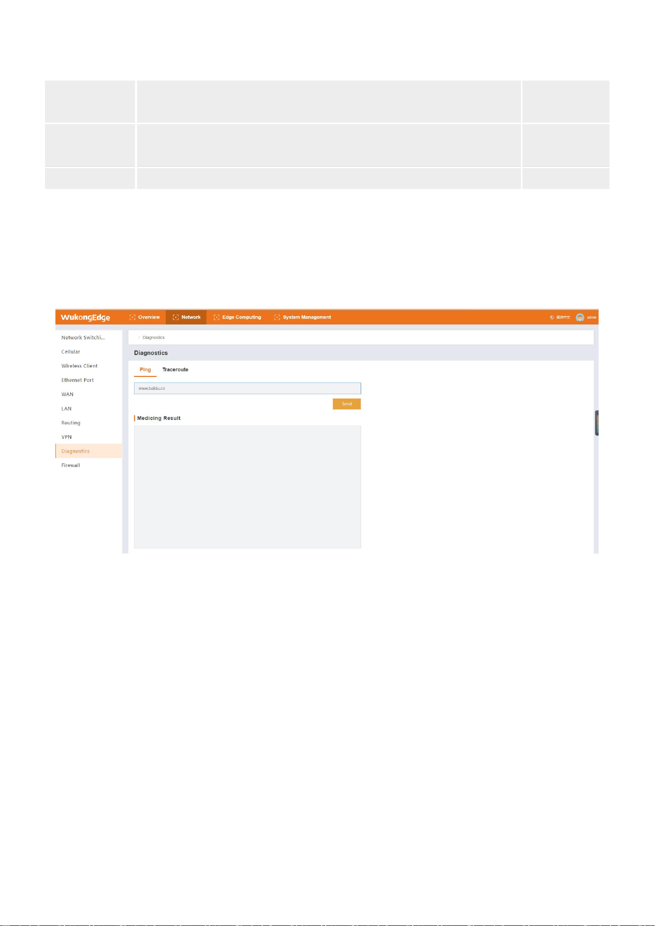
Network diagnostics include Ping tools and route resolution tools. The Ping tool on the router
side allows you to ping a specific address directly to determine network connectivity and latency.
Traceroute, as a routing analysis tool, can obtain the routing path through which data transmission
passes when accessing the address, and help to troubleshoot network faults
4.2.6.Network diagnosis
.
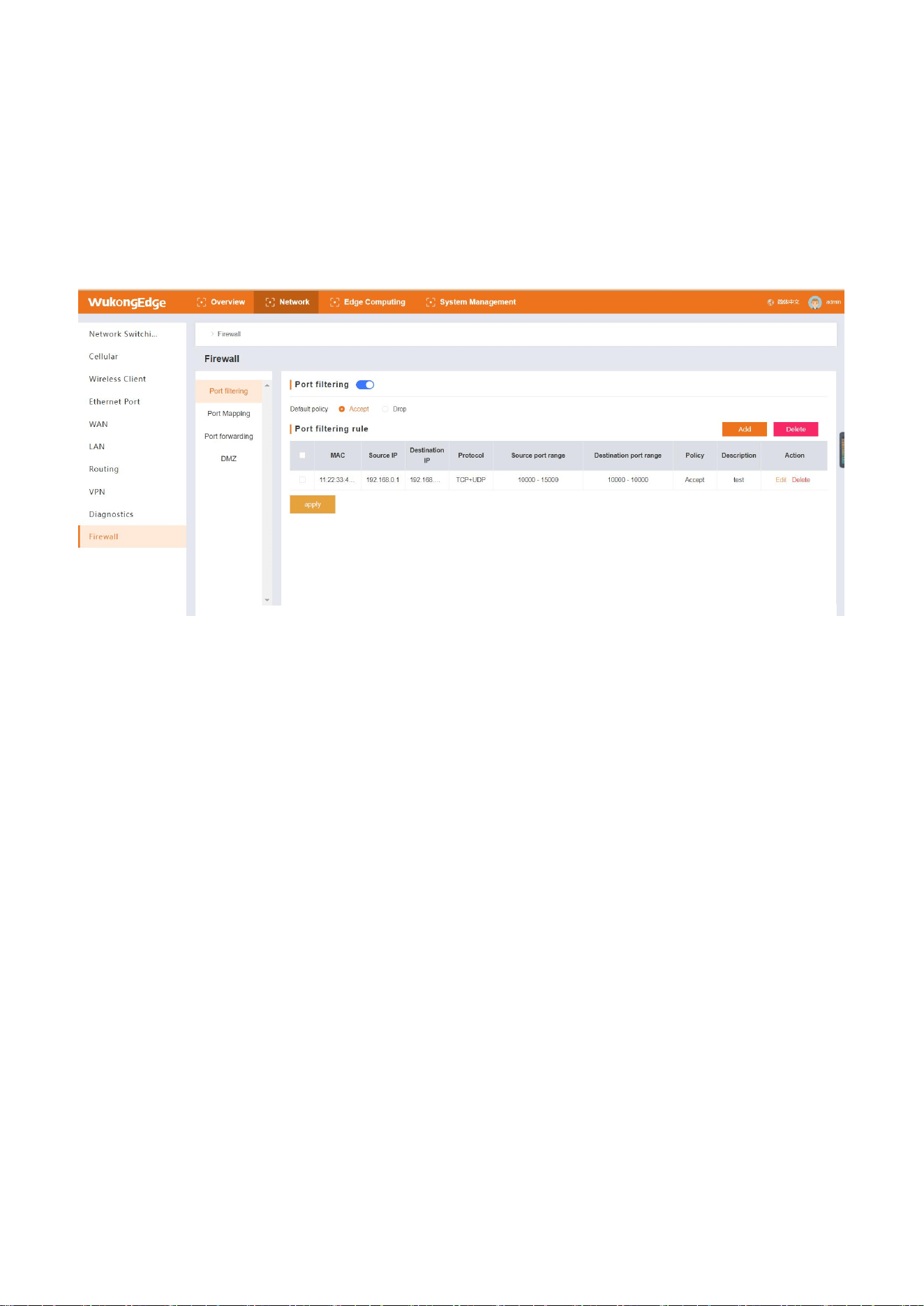
Firewall is the key line of defense to ensure network security. It skillfully integrates various
security management and screening tools to build a relatively isolated protective barrier between
the intranet and the extranet of the gateway, thus effectively protecting the data security in the
gateway. It has the following main tools
4.2.7.Firewall
:
Port filtering:fine control can be carried out on ports entering and leaving the network
according to preset rules, allowing only qualified port communication to pass through, blocking
illegal port access and greatly reducing the risk of network attack.
Port mapping:By mapping a specific port of the intranet to a designated port of the external
network IP, the external network users can access the intranet services, and the real IP of the
intranet is hidden to enhance network security.
23
Port forwarding:It can forward the network traffic of a specific port to other specified IP
addresses and ports, flexibly adjust the network data flow direction, and meet the needs of
different service scenarios.
DMZ (Quarantine Zone): Establish a special zone between the intranet and the extranet to
place servers that need to provide external services, both to ensure external access to these
services and to restrict access to the internal network, effectively isolating potential threats.
Operation steps:
Enter the built-in web page, find the "Network-> Firewall" interface, and select the firewall
option to be configured;
For example, configure port mapping, select port mapping, enter the interface, first enable,
pop up the rule adding interface.
In the parameter configuration interface, click Add to add mapping rules;
After adding parameters, click OK to complete adding a rule, and add multiple rules in the
same way;
Once all rules are set, click the Apply button and the application takes effect immediately.
4.4.Edge computing
In the industrial field, edge computing plays an irreplaceable key role, covering four core
functions: data acquisition, real-time calculation processing, result reporting and visual display.
In terms of data acquisition, edge computing equipment can quickly and accurately collect
massive data from various sensors and production equipment on the industrial production site,
whether it is temperature, pressure, vibration and other operating parameters, or product quality
data on the production line.

24
Real-time calculation and processing link, relying on the local powerful computing power, the
collected data can be analyzed instantly. For example, real-time monitoring and analysis of
equipment operation data is carried out to predict potential equipment failures in advance, to
achieve preventive maintenance, to ensure the continuity and stability of production, and to
greatly reduce downtime losses caused by equipment failures.
The processed key data will be reported to the industrial cloud platform or enterprise
management center system in time to provide decision-making basis for the management. Finally,
through the intuitive visual interface, key information such as production progress, equipment
status, quality indicators, etc. is clear at a glance, which is convenient for managers to grasp
production dynamics in real time, make scientific decisions quickly, optimize production processes,
and improve overall production efficiency and quality.
The WukongEdge application integrates these powerful edge computing functions. With its
highly integrated and efficient processing capabilities, it greatly meets the current industrial data
processing requirements and provides solid and powerful technical support for the digital
transformation of industrial enterprises.
4.4.1.Serial port management
Edge computing relies on hardware interfaces to achieve data acquisition, mainly network
ports, serial ports and IO interfaces. Network ports and IO have been introduced in the above
chapter. Hardware interfaces in this chapter mainly introduce serial ports. Parameter configuration
operations are as follows:
1、Enter the built-in web page, select the serial port used in the interface of "Edge
Computing-> Edge Gateway-> Serial Port Management";
2、After selecting serial port configuration interface to configure serial port enable, set baud
rate, data bit, stop bit and check bit;
3、Once configured, click Apply and restart the device to take effect.
When the hardware device is connected to the serial port screen, the protocol interaction
between the screen and the hardware device is often required to obtain the data in the data point
table through the serial port. At this time, the serial port will be used as the uplink communication
interface. WukongEdge also reserves a string of "serial port function" options at the exit end. Users
can freely switch the communication direction of the serial port to meet the data transmission
requirements.
Uplink communication interface:mainly used in combination with protocol conversion
function, providing serial port channel for northbound protocol acquisition;
25
Downward edge acquisition:mainly used in combination with edge acquisition function,
providing serial port channel for southward data acquisition.
4.4.2.Data point table
As the data cornerstone of gateway, data point table occupies the core position in the whole
data acquisition and transmission system. It is like a detailed information network, and each data
point is a key node of this network. The number of data points directly determines the breadth and
depth of gateway data collection. The more dense the points are, the more massive the data can
be captured by the gateway, which provides rich raw materials for subsequent analysis and
processing.
As the demand for data access increases, the performance of the gateway increases
significantly. A large amount of data not only enriches the information reserve of the gateway, but
also enables the gateway to have a richer judgment basis when analyzing the data. At the same
time, the gateway can make more accurate judgments in terms of equipment status monitoring,
production process control or abnormal situation warning, so as to ensure the efficient and stable
operation of the entire industrial system.
WukongEdge application integrates point table system, which can flexibly adjust the number
of point data according to different hardware adaptation. At the same time, the configuration
interface is simple, and it adapts to many acquisition protocols, which is suitable for more data
acquisition scenarios.
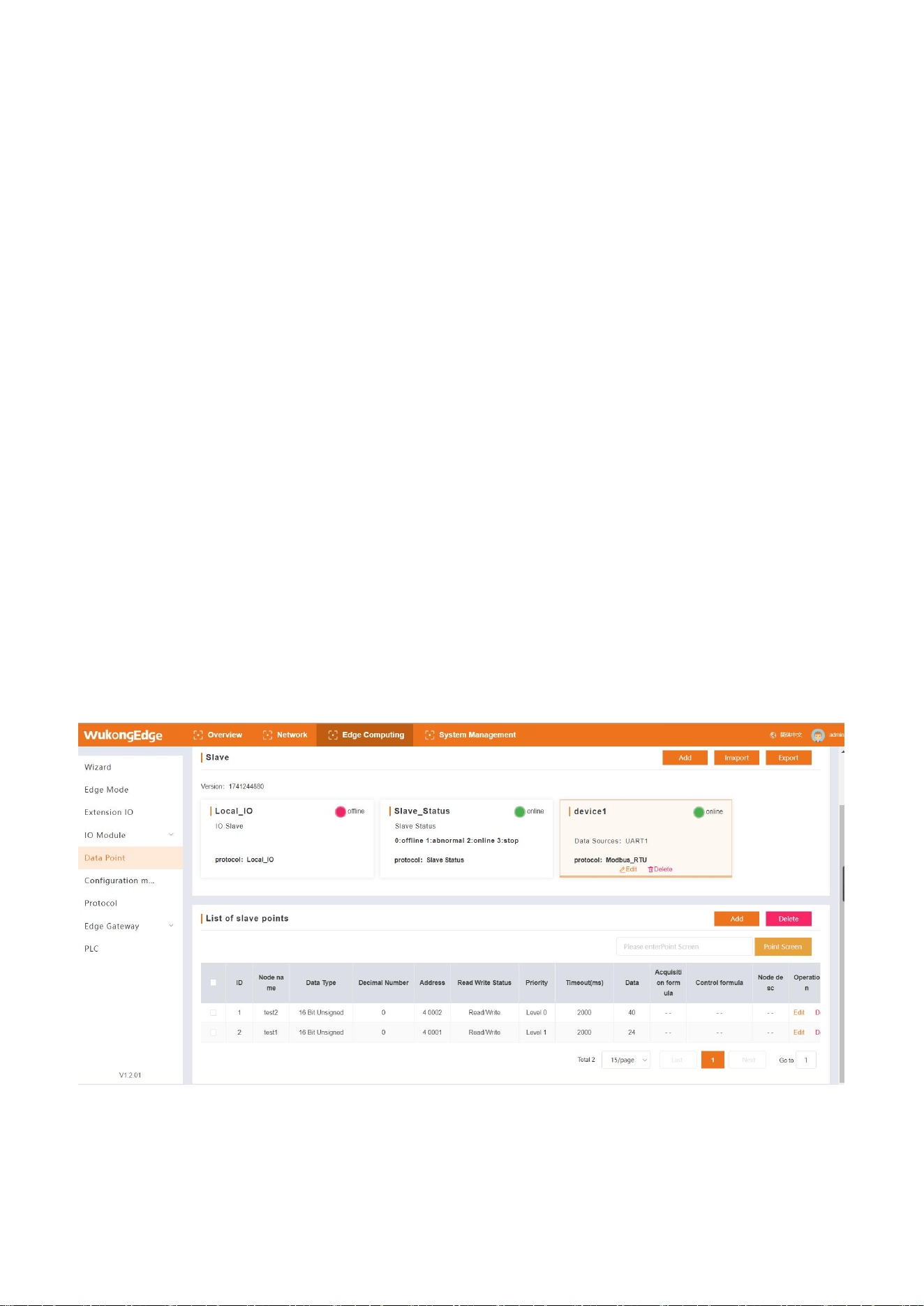
4.4.2.1.Slave and Point
As a key part of data acquisition, point table system includes two important components: slave
26
and point. The slave represents the collected equipment, such as various production equipment,
sensors, etc., while the point represents the specific data in the collected equipment, such as the
temperature and speed of the equipment. Detailed information is configured in the slave and point,
which is like accurate navigation, helping the gateway to accurately obtain data from the collected
equipment through a fixed interface, providing a solid data foundation for subsequent data
analysis and processing. The slaves of point table system are divided into fixed slaves and
configurable slaves.
The point data obtained by the fixed slave is mainly the parameters of the equipment itself, so
it does not need to be configured. There are mainly the following types:
System slave:mainly obtains system parameters of gateway itself, and stores and displays
each parameter as a point;
IO slave:When the gateway is connected to the IO expansion machine, the point table system
will automatically match the IO point information and realize data acquisition.
Status Slave: Each time a configurable slave is added, an online status point will be
automatically generated under the slave.
The slave can be configured to represent the acquired equipment, so the user needs to
manually add, configure the hardware interface corresponding to the acquired equipment, collect
relevant information such as protocols, and add corresponding point information under the slave.
Configurable slave supports multi-protocol selection, with different parameters for each protocol.
Specific parameters are described as follows:
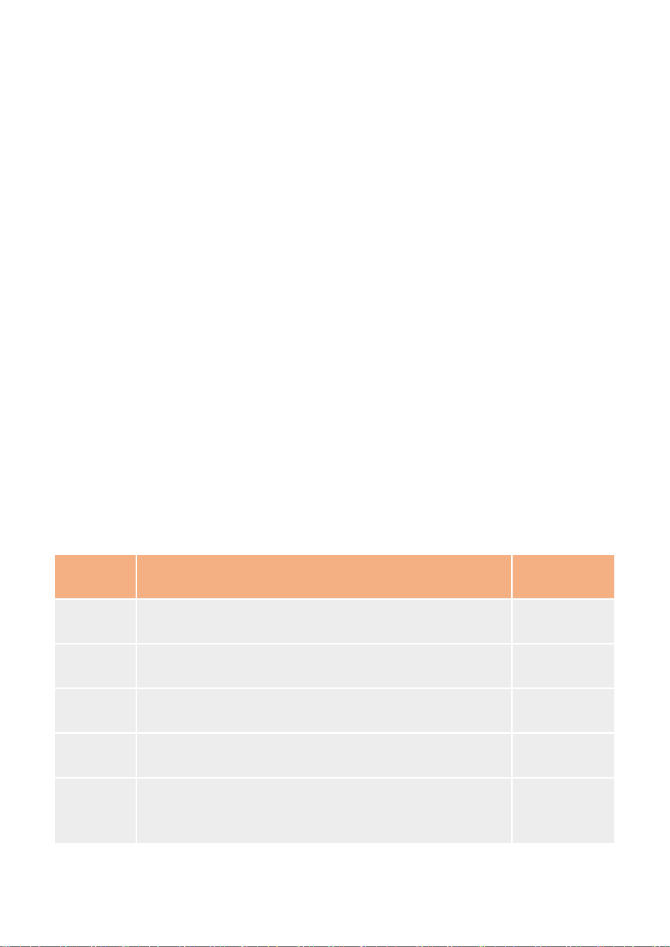
name
parametric description
default
parameters
Slave Name
1-64 byte, used as unique identification of slave,
non-repeatable, supporting Chinese
device1
slave
description
Support 1-64 bytes, including alphanumeric, Chinese,
underscore and connector
empty
acquisition
protocol
Protocols used for slave point active polling acquisition, Modbus
and multiple PLC protocols supported
virtual slave
polling
interval
The waiting time before each point acquisition command is sent,
ranging from 0 to 65535ms
0ms
combined
acquisition
Several consecutive address points in a single slave are
combined into one command for acquisition, and a maximum of
32 commands are used for acquisition.
open
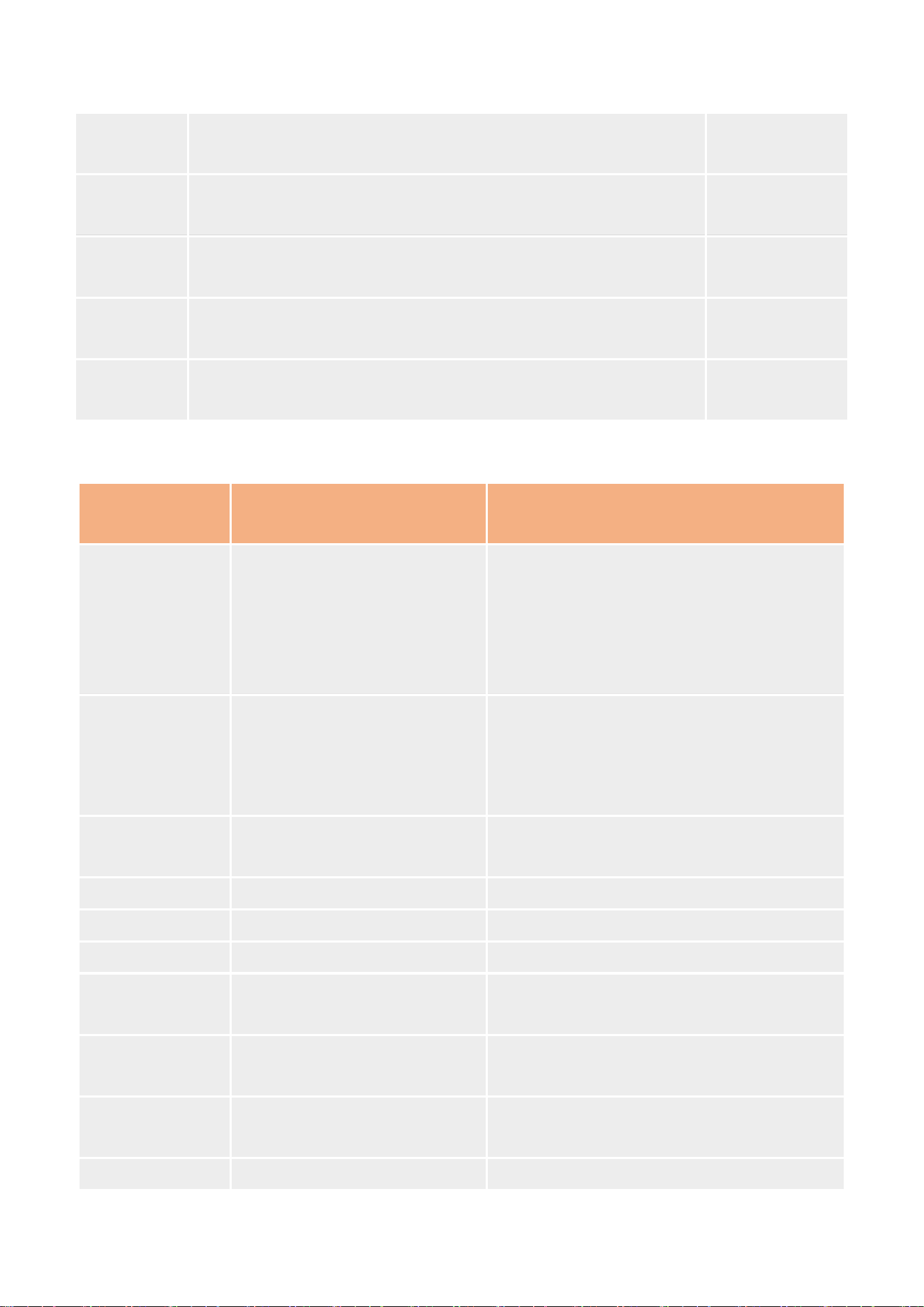
27
slave switch
When it is closed, all points under the slave will stop active
rotation training and data updating.
open
slave
address
Slave code of lower equipment, partial protocol settings
1
Serial serial
number
Point acquisition command sends serial serial port serial
1
IP
When collecting the network port, M300 is used as a Client, so it
needs to fill in the target IP and some protocol settings.
192.168.1.1
port
When collecting network port, M300 is used as Client, so it needs
to fill in target port and some protocol settings.
102
Slave acquisition protocol list:
acquisition
protocol
protocol description
range of application
Virtual-point
(Virtual Slave)
Calculation points
independent of acquisition
points
Virtual points can also be called calculation
points, which are new data obtained after
calculation of multiple collection points in
the point table system. Virtual points can
store up to 500.
Modbus RTU
Universal Serial Bus Protocol
485/232 serial communication bus
acquisition
Delta, ABB, Hollysys, Modicon and other
models PLC applicable
Modbus TCP
Universal Network Bus
Protocol
Suitable for network interface and other
network protocol bus acquisition
DVP_RTU
Delta PLC Protocol
Delta DVR series PLC acquisition
FATEK_COM
FATEK PLC Protocol
FATEK Fatek series (serial port)
FX protocol
Mitsubishi PLC Protocol
FX2N(1N)/ FX1S /FX3U
FX5U
Mitsubishi PLC Protocol
(MC3C/3E)
Mitsubishi FX5U Series (Net and Serial)
FX3U_ADP_TCP
Mitsubishi PLC Protocol
(FX3U_MC_ADP)
FX3U-ENET-ADP
Q_TCP
Mitsubishi PLC Protocol
(MC_TCP)
Mitsubishi Q Series PLC
S7_200 Smart
Siemens PLC protocol
S7-200 Smart
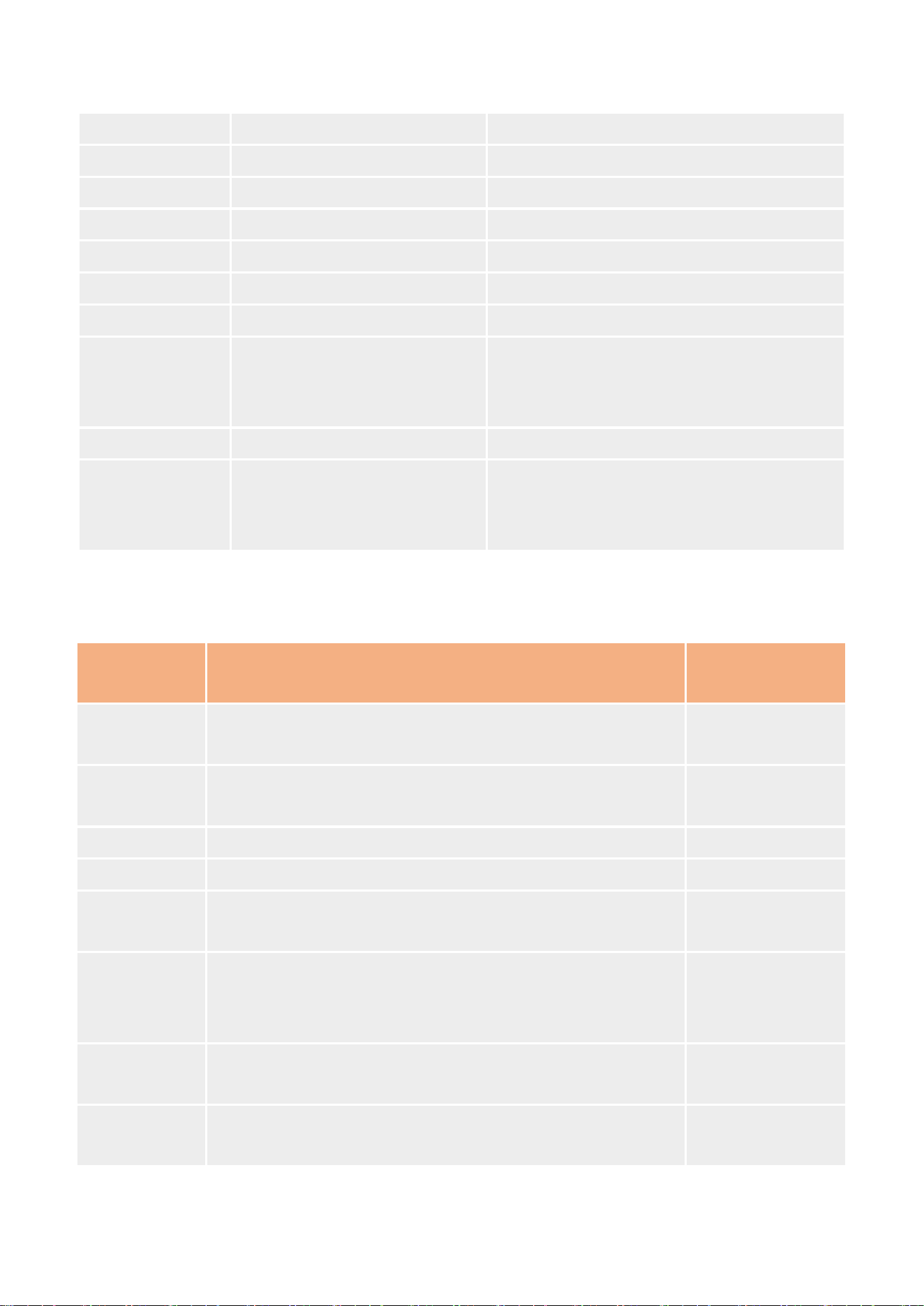
28
S7_200_PPI
Siemens PLC protocol
S7-200
S7_1200
Siemens PLC protocol
S7-1200
S7_1500
Siemens PLC protocol
S7-1500
S7_300
Siemens PLC protocol
S7 - 300 (net port)
S7_400
Siemens PLC protocol
S7-400 (net port)
FINS_TCP
Omron
CP Series
FINS_COM
Omron
CP Series
DL/T 645-2007
Communication protocol for
multifunctional electric energy
meter
Various types of meters
IEC104
electric power protocol
power data transmission
Bacnet IP
Building Automation Control
Network Data Communication
Protocol
Building sensors
After the slave is added, add the corresponding point information under the corresponding slave.
The point parameters are described as follows:
name
parametric description
default
parameters
Point name
1-64 byte, unique identifier of a point, not repeated with
any other point
empty
Point
Description
1-64 bytes, supporting characters, numbers and Chinese
empty
register
The storage type and storage address of the point
data type
Selection of Data Type for Point Collection
Number of
points
Add the total number of consecutive address points at a
time under the same slave, add in batches
1
number of
decimal
places
The number of decimal data displayed when the calculated
result of collected data is decimal
0
read-write
state
Read/write status of points. Different point types support
different read/write types.
read and write
*Priorities
When polling all points, the high-priority points shall be
preferentially collected according to periodic polling, and
empty
29
the real-time collection of high-priority points shall be
ensured.
acquisition
formula
Point calculation formula, the collected data is stored and
provided to other functions after calculation according to
the formula inside the equipment.
empty
control
formula
When writing to this point, the result will be written to the
terminal device after calculation by the control formula
empty
timeout
In the process of point polling acquisition, the longest
waiting time for reply after issuing the command. The
acquisition will be automatically abandoned after timeout,
and the historical data will not be updated and the next
acquisition command will be executed. Range: 10~3000ms
2000ms
unit
Non-mandatory parameters, set as needed
empty
Note: Priority functions are under development.
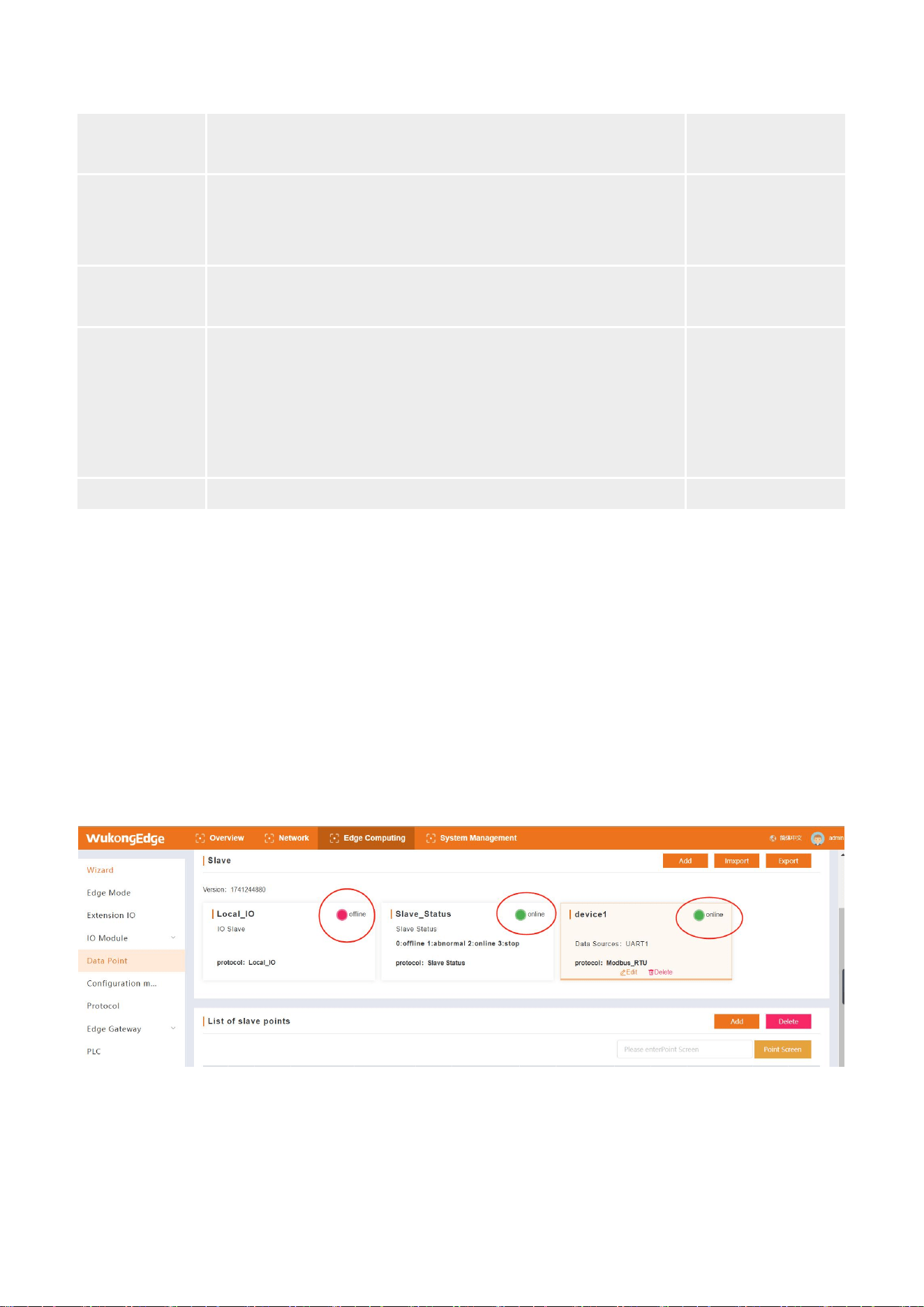
4.4.2.2.Slave status
The status display function of data points allows users to intuitively view the online status of
slaves from the built-in web page. The slave status is divided into online, offline and abnormal.
On-line: All data collection of slave internal points is successful, and the corresponding slave
status point value in slave status is 2;
Off-line: all data acquisition failed at slave internal points; status slave internal corresponding
slave status point value is 0;
Abnormality: partial data acquisition of slave internal points is successful; status slave
internal corresponding slave status point value is 1.
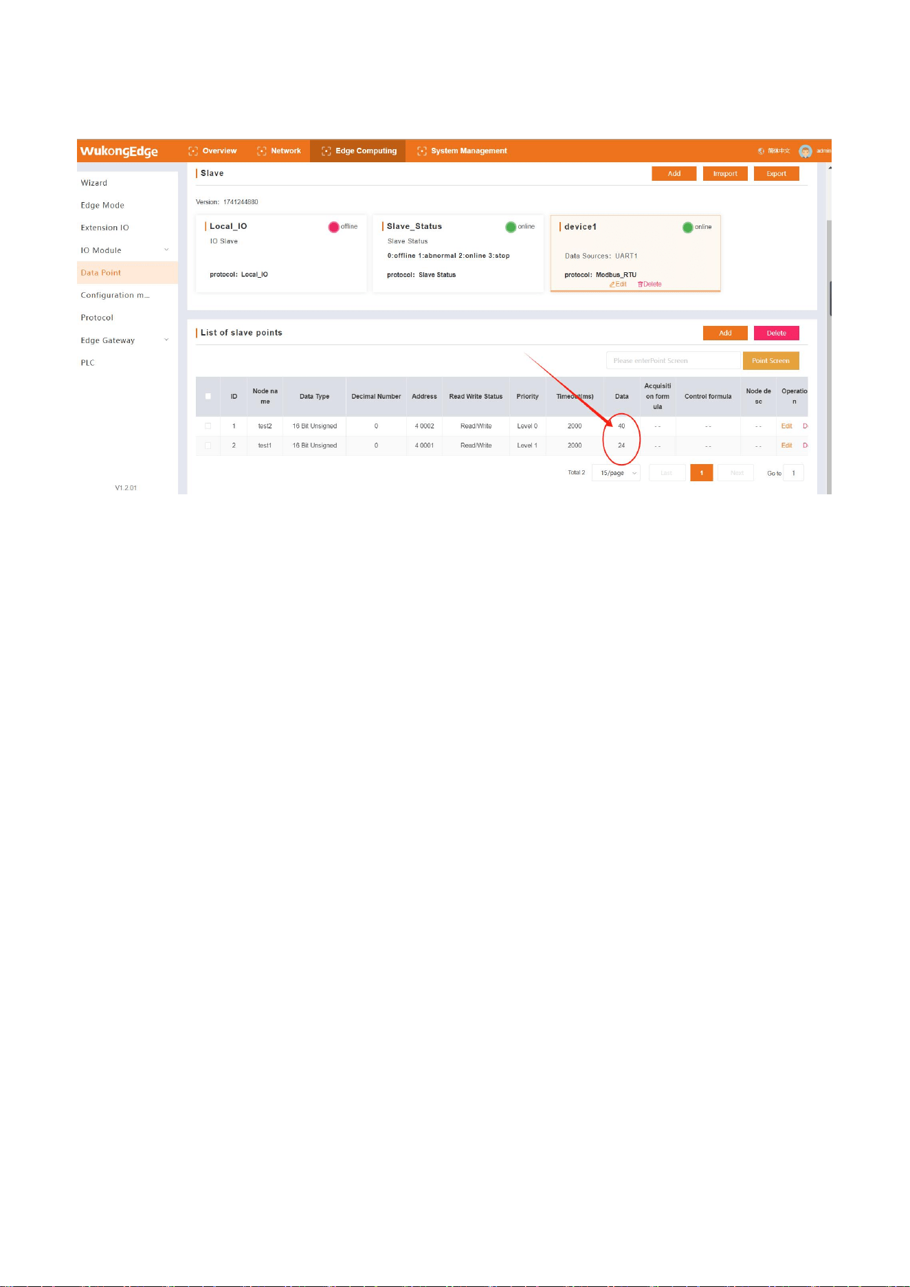
4.4.2.3.Point location data
After the slave point in the data point table obtains the data, it can be displayed on the built-in
web page, and the data is continuously updated along with the collection, so that it is convenient
30
for users to directly observe the data in the device.
4.4.2.4.Import and export
In Wukong Edge's point system, the point information of the data point table needs to be
added manually. When only part of the information of some points is different, editing with Excel
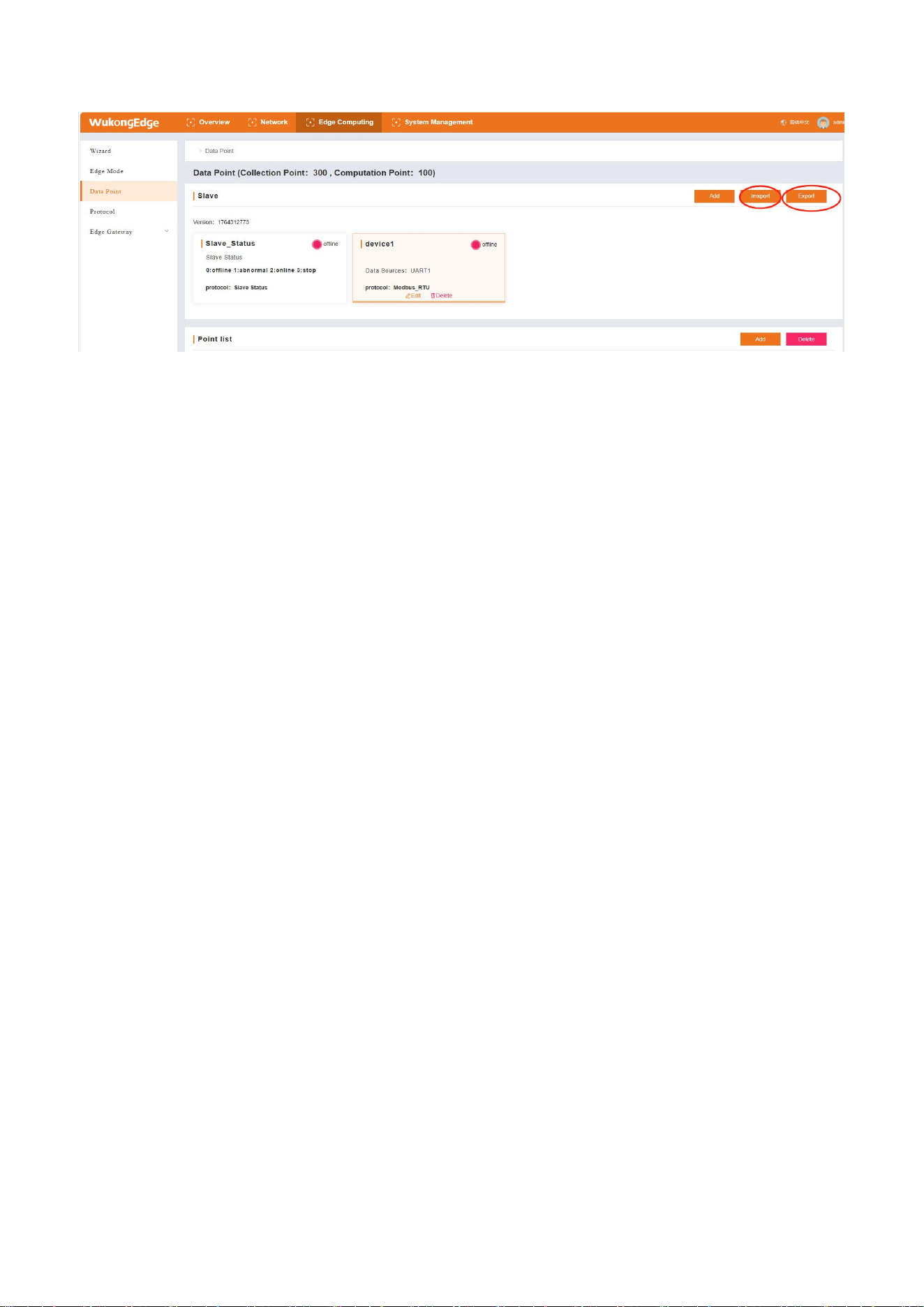
and other tabular tools can greatly improve efficiency. For this reason, WukongEdge's point system
integrates point export and import functions. Users can export the point template first, quickly edit
the point information in the familiar table environment, and then import the edited file into the
equipment. In this way, the point addition work can be completed more efficiently and
conveniently, greatly saving labor and time costs.
Operation steps:
1、When using for the first time, it is recommended to add a slave and point to the equipment
before exporting. The corresponding addition example will be displayed in the file;
2、Find the "Edge Calculation-Data Point" interface, find the "Export" button, click to download
the point table template file;
3、In the downloaded CSV file, fill in the relevant parameters of the slave machine and the
point according to the header, and save the file after filling in;
4、Find the "Edge Calculation-Data Point" interface, find the "Import" button, click and select
the saved file to upload;
5、After the equipment identifies the file, it will automatically pop up the corresponding slave
and point, and prompt to restart the equipment;
6、The device restarts and performs data acquisition functions after startup.
31
4.4.3.Edge acquisition
The edge acquisition function is mainly realized by hardware gateway equipment. When
actively collecting sensor data, the gateway device first needs to input the data information of the
collected device, that is, the addition of the data point table, and then the gateway can
automatically obtain data from the collected device according to this information, and store the
obtained data.
The edge acquisition process involves configuration of the point table, configuration of the
acquisition interface. The active collection operation steps are as follows:
1、Enter the built-in web page, add slaves in the "Edge Calculation-> Data Points" interface,
and select the corresponding communication interface;
2、Add the corresponding point information under the added slave machine to complete the
addition of all points;
3、After configuration, restart the device;
4、After the equipment restarts, the equipment will actively send data acquisition commands
from the corresponding interface to the acquired equipment, receive the reply content, and
analyze the data;
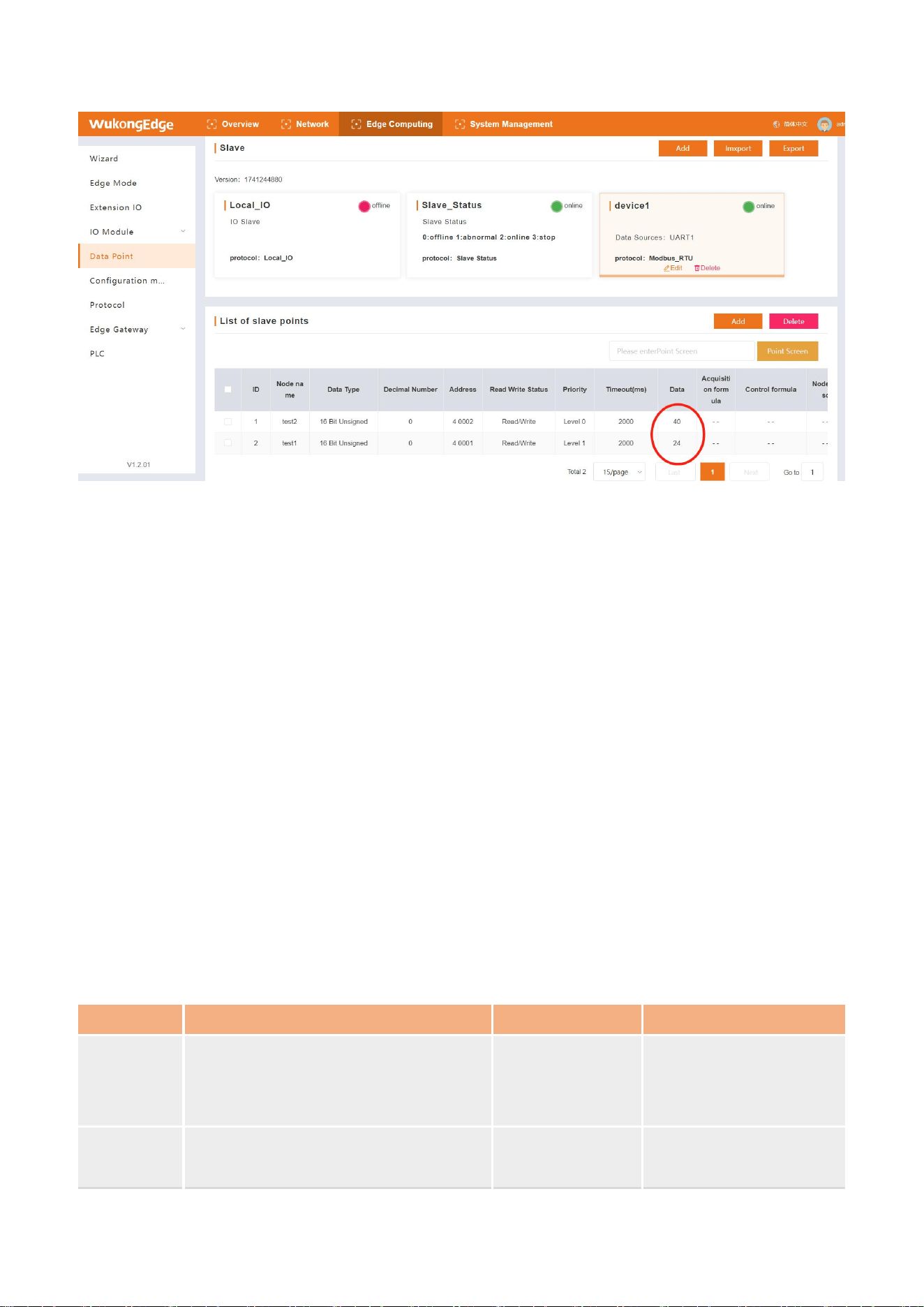
5、In the point table system, the most recently acquired data for each point will be displayed.
32
4.4.4.Edge computing
After the data acquisition is completed, with the chip's high-speed computing ability,
preliminary data processing is carried out, which significantly speeds up the data processing
speed. Moreover, the data is processed locally, which reduces the exposure risk of data during
network transmission and effectively guarantees data security. In addition, a large amount of data
is initially processed locally, reducing the amount of data uploaded to the server, thereby reducing
the load pressure on the server and making the entire system run more efficiently and stably.
WukongEdge integrates two ways of data single-point calculation and data multi-point
calculation, both of which are realized through calculation formulas, and supports five operations:
addition, subtraction, multiplication and division and (). The data calculation is to configure each
point separately directly when adding points to the point table.
Single-point calculation: The single-point calculation object is the collection point, and the
data is obtained through active collection. When adding acquisition points, fill in the
corresponding formula in the point acquisition calculation and control calculation parameters,
pull only the current point data in the single point calculation formula, and fill the data
calculated according to the formula into the storage position of the point.
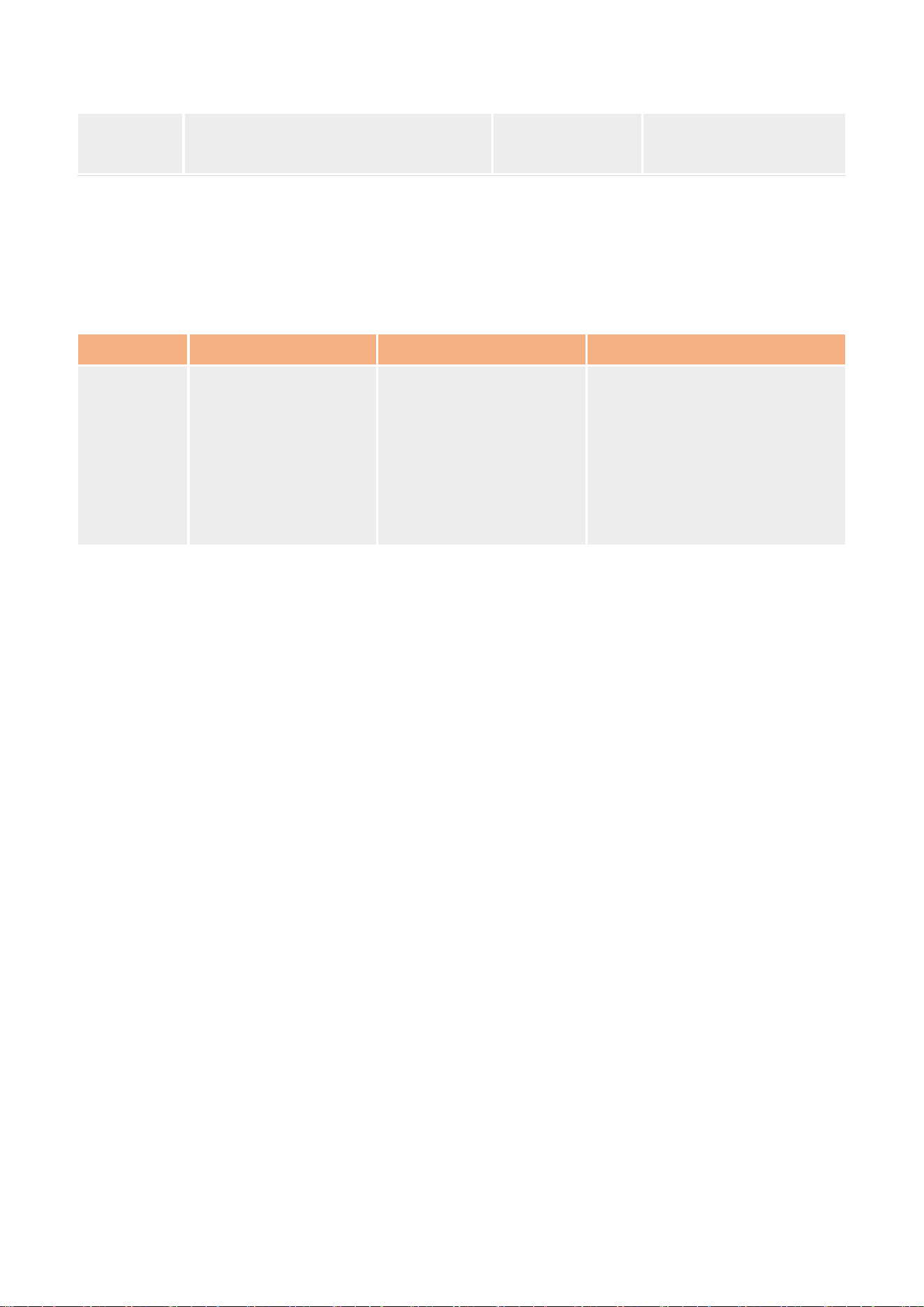
Parameter
Function
Formula Style
Parameter specification
acquisition
formula
calculating the collected data to
obtain a result, storing the result and
waiting for reporting to the server
=(%s+10)/2
%s represents the point
data before the point
control
formula
Receive the control data sent by the
server, calculate the result and send
=(%s*2)-10
%s represents the point
data before the point
33
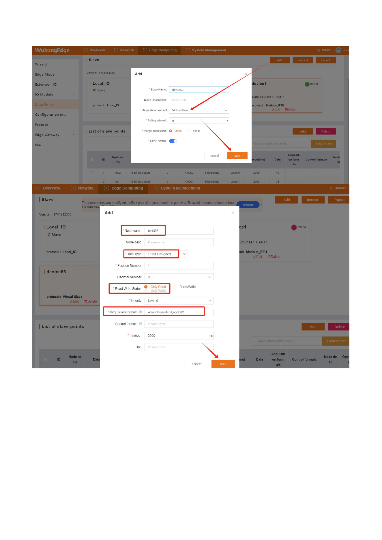
Multi-point calculation: You need to add a virtual slave, and add a virtual point under the
virtual slave. When adding, fill in the corresponding formula in the collection formula. In the
multi-point calculation formula, the data of multiple collection points will be pulled for
calculation, and the calculated result will be filled into the virtual point.
Virtual slaves and virtual points are added as follows:
1、Enter the built-in web page, and add slave machines in the "Edge Computing-> Data
Points" interface, where "Virtual Slave Machine" is selected for the acquisition protocol;
2、After adding slave machine, select virtual slave machine and add virtual point, set data
type and collection formula;
3、The control formula of virtual point can be set to null, and the read-write status can be set
to read-only;
4、After configuration, restart the device;
5、After the equipment is restarted, when the data acquisition of the points involved in the
virtual point acquisition formula is completed, the corresponding virtual points will also display the
calculated data;
it to the acquired equipment to
realize parameter control.
Parameter
Function
Formula Style
Parameter specification
acquisition
formula
calculating the
collected data to
obtain a result and
storing the result to
wait for reporting to
the server
=(%s+10)/%s,node0101,
node0102
The first %s represents the data
after acquisition at node0101
The second %s represents the
data after acquisition at
node0102
34
4.4.5.Actively report
Escalation is a critical finishing touch for edge computing. After data collection and local
calculations are completed, the resulting data results are transmitted to the server. These data
processed by edge computing provide the basis for the server to carry out more complex analysis,
processing and visualization. Active reporting is that after the edge calculation is completed, the
system will actively encapsulate the data according to the Json format, and then report the data to
the server accurately through the network. This method not only ensures the standardization of the
data transmission format, but also improves the autonomy and efficiency of data transmission,

35
and strongly supports the deep data application of the server side.
In WukongEdge application, the active reporting function is divided into two parts:
communication link and data reporting, which will be introduced separately.
4.4.5.1.Communications link
The communication link serves as a network channel for reporting data to the server, providing
a variety of connection modes to meet the needs of different users. It supports TCP connection,
MQTT connection, HTTP connection, users can choose the appropriate connection method
according to their own business needs. In addition, in order to ensure the security of data
transmission, the communication link also supports TLS/SSL encryption, and provides a variety of
encryption methods for users to choose independently, further enhancing the confidentiality and
integrity of data transmission. In the process of configuring the report packet, the corresponding
communication link needs to be selected,so the configuration of the communication link needs to
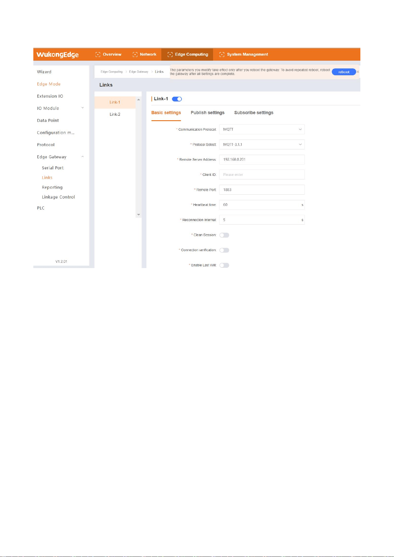
be completed first. The specific operations are as follows:
1、Enter the built-in web page, and enable the required communication link in the "Edge
Computing-> Edge Gateway-> Communication Link" interface;
2、Configure the enabled communication link parameters. TCP,MQTT and HTTP can be
selected as communication protocols.
3、Configure encryption method and upload certificate, and configure network disconnection
cache enable;
4、After configuration, click the "Apply" button to save;
5、If MQTT communication is selected, configure corresponding publishing topics and
subscription topics after basic parameter configuration is completed;
6、After all communication link parameters are configured, the device needs to be restarted to
take effect.
36
4.4.5.2.Network disconnection cache
WukongEdge has a very critical feature of having a network break cache built into the
communication link. In the event of a network failure, it can quickly store the data being reported
properly to ensure that the data is not lost due to network disconnection. When the network returns
to normal, it will automatically report the cached data to the server accurately, thus ensuring the
integrity of the data in all aspects.
The network disconnection cache function stores the complete data packets reported actively
instead of single data. After the network replies, the cache data is reported to the server according
to the first-in-first-out principle to achieve fast and accurate reporting.
4.4.5.3.Json template
The reporting data format of active reporting is Json custom template, so before introducing
active reporting, first understand the configuration method of Json template for reporting.
The active reporting data format can be configured as long as it conforms to the Json format,
which is generally configured by the client according to the server requirements.
However, Json
template configuration needs to pay attention to the following points:
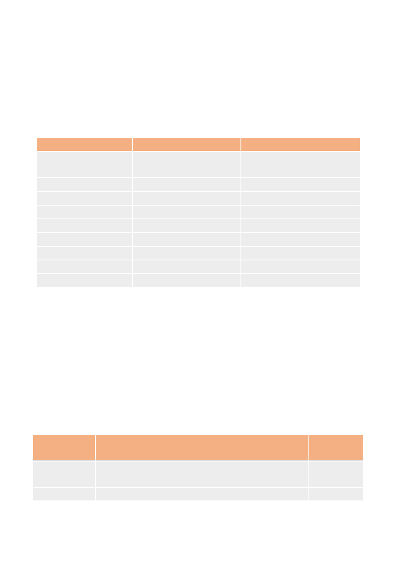
1、Json template in grouping is empty by default. You can design it yourself and meet the
requirements of Json format.
37
2、Value in Json template is character type, which needs to be filled in data point name. When
data is reported, the actual acquisition value corresponding to point name will be substituted for
replacement;
3、Example: The acquisition values of node0101 and node0102 at the edge are 30 and 20
respectively; the Json template is set to {"Current":"node0101","Voltage":"node0102"}; the actual
report data format is {"Current":30,"Voltage":20}.
4、System points can be reported as data points.
Identification
Implication
Example of Reporting Content
sys_ver
Product firmware version
number
V1.0.14.000000.0000
sys_imei
IMEI
864452061930390
sys_sn
SN
02700122093000012356
sys_mac
MAC
D4AD20474662
sys_iccid
ICCID
89861122219045577705
sys_local_time
local time
2023-05-27,22:35:44
sys_utc_time
UTC time
2023-01-12T18:15:02Z
sys_timestamp
timestamp
1706167861
sys_timestamp_ms
millisecond timestamp
1601196762389
4.4.5.4.Actively report
WukongEdge's built-in proactive reporting adopts grouped reporting mode. Users can
independently select different communication links and points for different groups according to
actual needs, so that they can flexibly report data to different servers respectively, and easily
achieve multi-link and multi-platform data sharing.
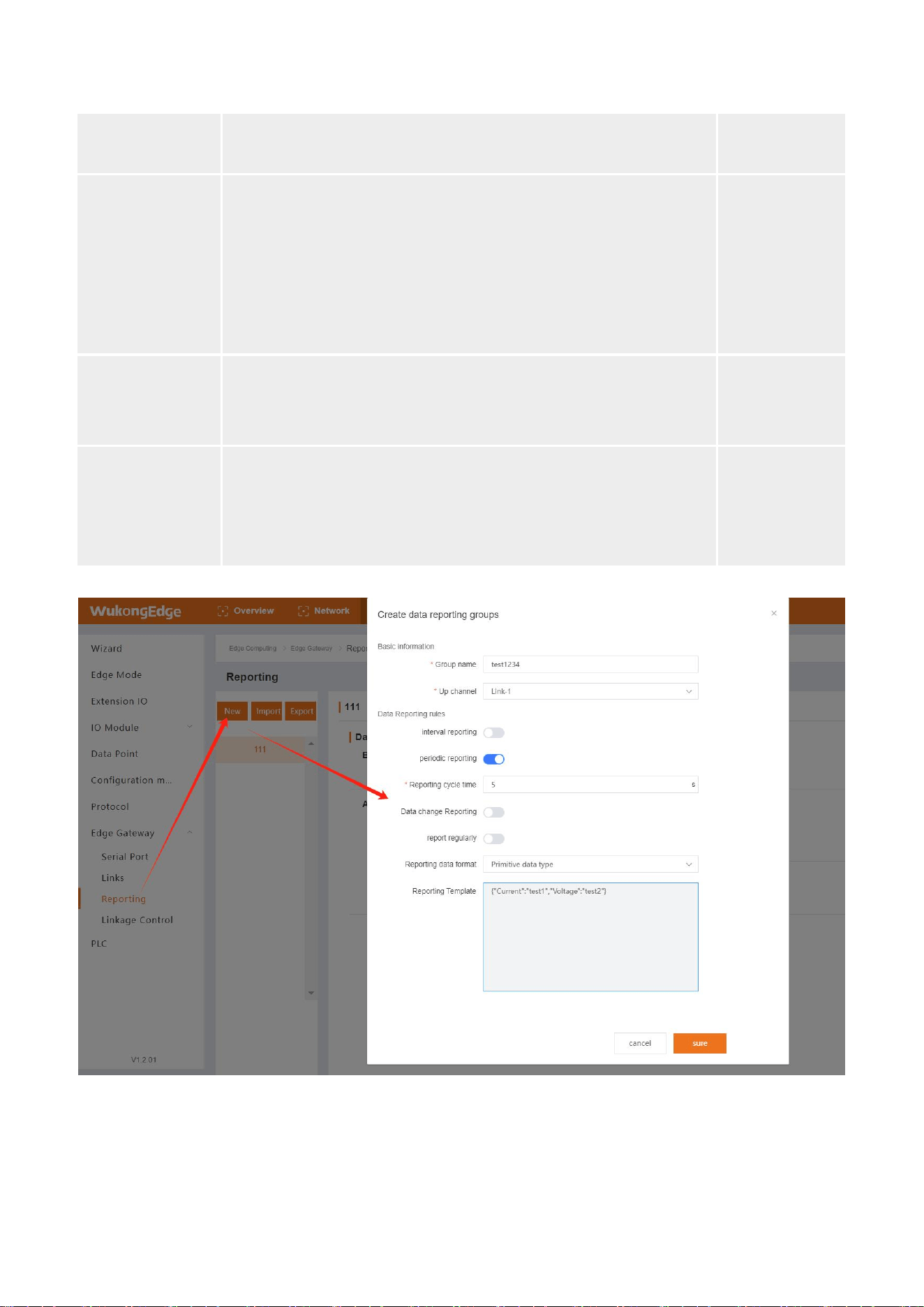
The specific operation of group active reporting is as follows:
1、Enter the built-in web page, click the "Create" button in the "Edge Computing-> Edge
Gateway-> Data Reporting" interface to create a reporting group;
2、Select the reporting channel and configure parameters such as reporting Json template and
reporting conditions;
name
parametric description
default
parameters
upward channel
For actively reported data network channels, you can select
cloud/link 1/link 2
empty
Reporting Rules
Support four reporting conditions
empty
38
(interval/cycle/change/timing reporting), support multiple
choices
Reporting data
format
Original type: Point data is reported to the server according to
the original type.
Digit to character: if the point data is of digital type,"" will be
added when reporting, and the digital format will be
converted into character string format, and then reported to
the platform.
empty
Submission
template
Custom Json, need to comply with the Json format
specification, template maximum 8K bytes.
empty
table of points
Each active reporting group is taken as an independent
individual, and the points to be reported in this group are
pulled from the overall data point table as the point table
used by this group alone.
empty
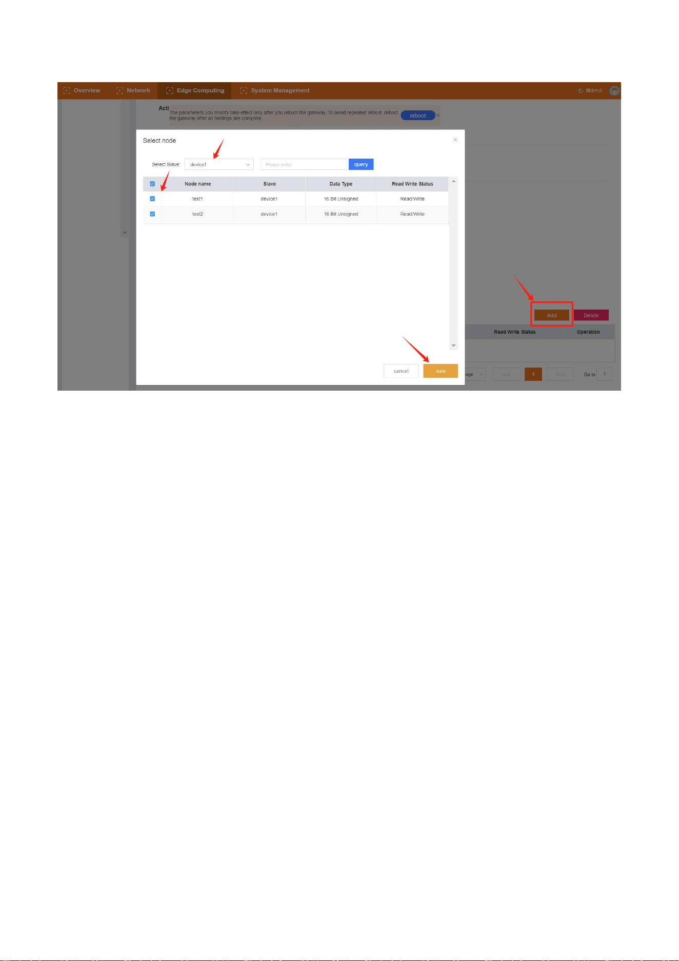
3、After completing the group addition, find the point list in the group and click the "Add"
button, and the pop-up window will pop up;
4、Select the corresponding slave machine and point, click OK (when there are many points in
the slave machine, you can select the slave machine and directly search for the point name);
39
5、After the selection is completed, complete the addition of the report group, and restart the
equipment to make the report group effective;
6、Wait for the device to connect to the server successfully, and then check the data report
status.
4.4.6.Protocol conversion
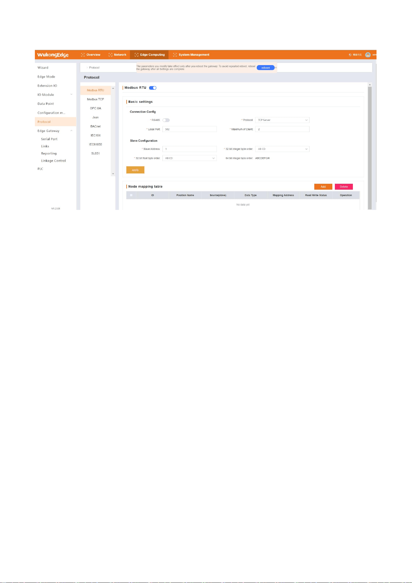
WukongEdge's protocol conversion function constructs standardized protocol interaction
channels between data and servers. Through edge computing capabilities, hardware interfaces
are able to collect data for a variety of different protocols. These data will be uniformly converted
into a fixed protocol under the operation of the protocol conversion function, thereby achieving
smooth interaction with the server.
The protocol conversion function supports multiple protocols, including Modbus RTU, Modbus
TCP, OPC UA, JSON, Bacnet, IEC104, IEC61850, SL651. The protocol conversion function allows
multiple protocols to communicate in parallel at the same time, and each protocol has an
independent operating mechanism without interference with each other. In addition, there is an
independent data mapping table under each protocol, which ensures the stable and efficient
operation of the protocol conversion process and provides a solid and reliable technical guarantee
for various complex industrial scenarios and diversified data interaction requirements.
40
The logic used by the protocol conversion function is to perform the following operations on
the basis of the completion of the configuration of the data point table:
1、Go to the built-in web page, select the matching protocol to configure in "Edge
Computing-> Protocol Conversion"
2、Enter the selected protocol interface, configure the protocol enable, and set the relevant
parameters;
3、After parameter configuration is completed, click "Apply" button to save parameters;
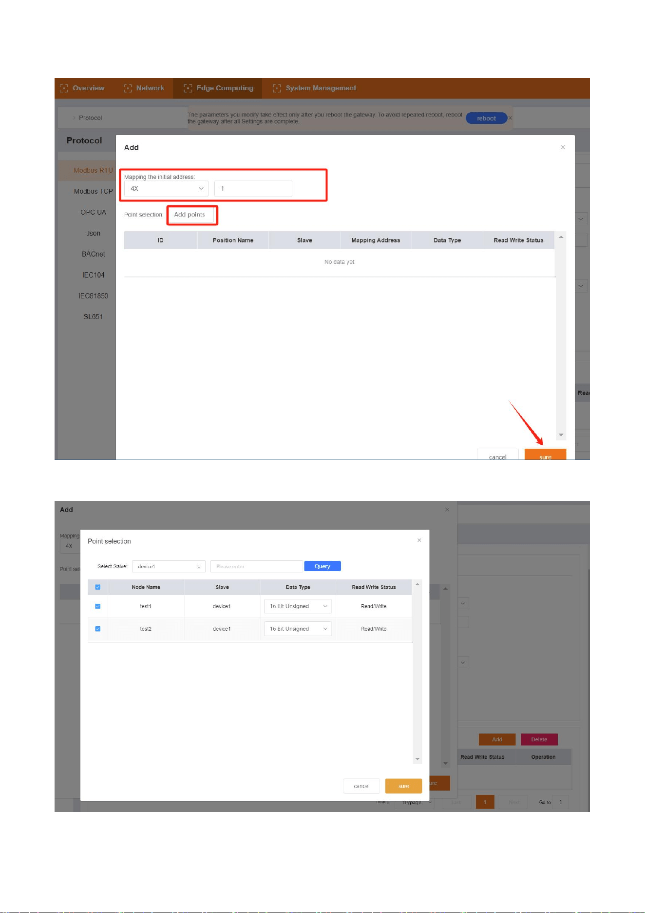
4、To add a point mapping, find the "Point Mapping Table" on the selected protocol interface,
click the "Add" button, and a pop-up window pops up;
41
5、Set the mapping address in the pop-up window, click the "Add Point" button, and pop up
the point selection pop-up window;
6、Select slave and point, configure the point data type, and click OK to return to the next level
42
after confirmation;
7、After returning to the mapping address configuration pop-up window and confirming that
there is no error, click the "OK" button to complete the mapping address addition;
8、After basic parameters and point mapping are all set and saved, it will take effect after
restarting the equipment;
9、After the device restarts, wait for the device to connect to the server, and then normal
protocol communication can be realized.
4.4.7.Linkage control
WukongEdge's linkage control function is dedicated to achieving local closed-loop
management and rapid response to alarm and emergency needs. It relies on local edge
acquisition technology to acquire data in real time, and then efficiently complete data processing
and judgment within the application. The whole process quickly executes corresponding actions
according to preset conditions. Because there is no need to rely on the network to transmit data, it
effectively avoids the interference of external factors such as network delay, realizes quick
response, greatly improves the timeliness and accuracy of local management, and provides
reliable technical guarantee for various scenarios with high real-time requirements.
Linkage control exists in the form of events, and the upper limit of linkage control events set in
the application is 50. On the premise of edge acquisition and data acquisition, linkage control can
43
be configured by referring to the following steps:
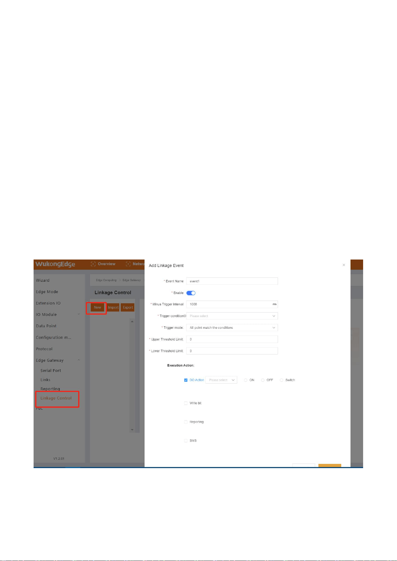
1、Enter the built-in web page, click the "Create" button to add in the "Edge Computing-> Edge
Gateway-> Linkage Control" interface;
2、Configure corresponding parameters such as event name. The parameters are introduced as
follows:
name
parametric description
default parameters
event name
Linkage event name, user-defined
event1
event switch
Enabling of linked events
open
minimum trigger
interval
When the linkage event meets the trigger condition for
many times in a short time, the minimum interval of
trigger execution is executed, and the trigger within
the minimum trigger time does not execute the action
and is directly discarded.
1000ms
trigger condition
The judgment conditions of linkage events are met,
and the actions are executed. There are 10 conditions
in total.
empty
trigger point
Linkage conditions judge the source of the required
data, support multi-point selection
empty
trigger mode
Trigger logic between multiple points when multiple
trigger points are selected
All points meet the
conditions
the upper
threshold
Maximum range of threshold conditions, range
0~20000
0
the lower
threshold
Range minimum of threshold condition, range
0~20000
0
perform an action
Actions to be executed after linkage event meets
trigger conditions
empty
3、Configure trigger conditions and select trigger points. Trigger conditions are described as
follows:
trigger
condition
describe
explain
forward
following
DI closed, DO closed; DI open, DO open
Trigger points only
support switching
values
reverse
DI closed, DO open; DI open, DO closed
Trigger points only
44
following
support switching
values
greater than or
equal to
Trigger action when detection value is greater than or
equal to set threshold
Set lower threshold
only
greater than
Trigger action when detection value is greater than set
threshold
Set lower threshold
only
less than or
equal to
Trigger action when detection value is less than or equal
to set threshold
Set only the upper
threshold
less than
Trigger action when detection value is less than set
threshold
Set only the upper
threshold
Within the
interval
(including
boundaries)
The detection value triggers an action within the
threshold interval, and triggers an action within each
entry interval.
Set upper and lower
thresholds
Within the
interval
(excluding
boundaries)
The detection value triggers an action within the
threshold interval, and triggers an action within each
entry interval.
Set upper and lower
thresholds
Outside the
interval
(including
boundaries)
The detection value triggers an action outside the
threshold range, and the outgoing interval triggers an
action once
Set upper and lower
thresholds
Outside the
interval
(excluding
boundaries)
The detection value triggers an action outside the
threshold range, and the outgoing interval triggers an
action once
Set upper and lower
thresholds
4、Configure execution actions, and execute actions simultaneously and in parallel;
trigger
action
describe
explain
DO action
Select DO interface of equipment and output
corresponding actions (close, open and flip)
DO is single choice
write
data
point
Write pre-set data to pre-selected points
Data points pulled from
the data point table
45
reporting
platform
Cloud platform that uploads customized alarm information
through links to achieve rapid alarm
MQTT requires a separate
theme
send
short
messages
Send customized alarm information to mobile phone
through SMS to realize fast alarm
SMS content is within 70
bytes
5、After completing all parameter configuration, confirm that there is no error, click the "OK"
button, and restart the equipment according to the prompt;
6、After the equipment restarts, after collecting data at the edge, the linkage control will judge
and execute corresponding actions.
4.5.Node-Red
WukongEdge app has the latest version of Node-Red built in and uses low-code graphical
programming mode. Developers can quickly build application logic by simply dragging and
connecting, and can complete complex data processing and process control tasks without writing
a lot of code. This greatly reduces the development threshold, improves development efficiency,
and helps developers quickly turn ideas into practical applications.
Graphical development and edge computing make the localization of complex logic data more
efficient and fast.
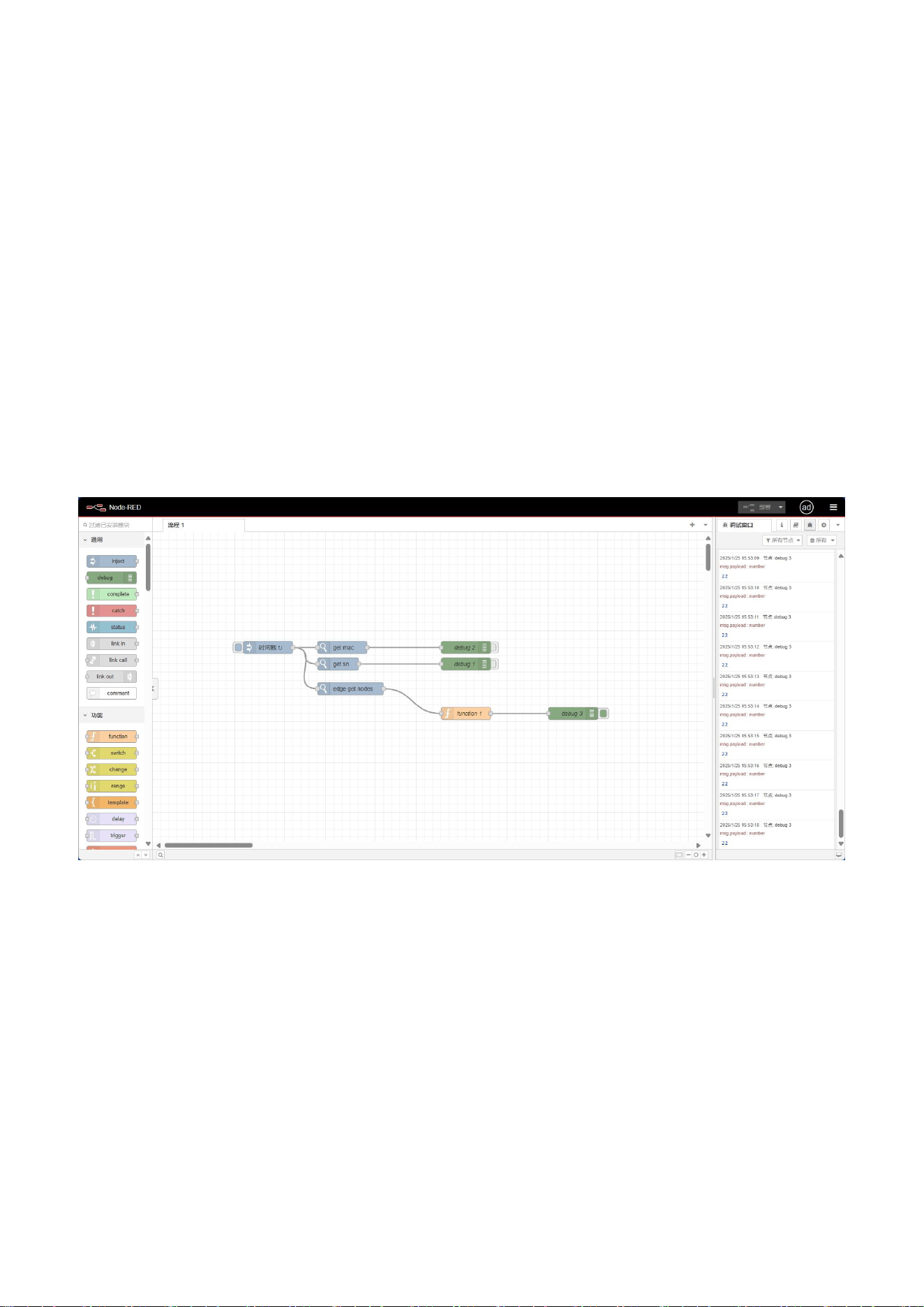
The use method is also very simple, just need to find "edge calculation-> mode management"
in the built-in web page, set the edge calculation mode to "edge + graphical", and then restart the
device, after the restart, also in the interface, click the "graphical design" button, you can enter the
graphical editing interface.
46
In Node-Red's graphical editing interface, the layout of each area is clear and the division of
labor is clear, which greatly improves the user experience. Rich and diverse nodes are neatly
arranged on the left side of the interface, covering various functions such as data input, processing
and output. In the middle of the interface is the design area.Users can freely select the required
nodes from the left side, drag them to this area, and intuitively establish the logical relationship
between nodes through connections, so as to easily construct complex and efficient data
processing processes.
There is a deploy button at the top of the right side of the interface. With a single click, you can
quickly deploy the designed process to the system. Below the button is the debugging area, which
displays various information and data of process operation in real time to help users find and solve
possible problems in time to ensure stable and accurate operation of the whole process.
Basic operation steps: pull node-> design logic-> deployment logic-> debugging
optimization-> final deployment.

FCC Statement
This device complies with part 15 of the FCC rules. Operation is subject to the following two
conditions: (1) this device may not cause harmful interference, and (2) this device must accept
any interference received, including interference that may cause undesired operation.
Changes or modifications not expressly approved by the party responsible for compliance could
void the user's authority to operate the equipment.
NOTE: This equipment has been tested and found to comply with the limits for a Class B digital
device, pursuant to part 15 of the FCC Rules. These limits are designed to provide reasonable
protection against harmful interference in a residential installation. This equipment generates
uses and can radiate radio frequency energy and, if not installed and used in accordance with the
instructions, may cause harmful interference to radio communications. However, there is no
guarantee that interference will not occur in a particular installation. If this equipment does
cause harmful interference to radio or television reception, which can be determined by
turning the equipment off and on, the user is encouraged to try to correct the interference by
one or more of the following measures:
• Reorient or relocate the receiving antenna.
• Increase the separation between the equipment and receiver.
• Connect the equipment into an outlet on a circuit different from that to which the receiver is
connected.
• Consult the dealer or an experienced radio/TV technician for help.
This equipment complies with FCC radiation exposure limits set forth for an uncontrolled
environment. This equipment should be installed and operated with minimum distance 20cm
between the radiator & your body.