ŅŔĴĶIJŃ
ĶĮŅųŪŷŦŴġŦŔłŕłġŎŶŭŵŪŮŦťŪŢġņůŤŭŰŴŶųŦ
Support RAID 0, 1, 10, 5 (*Windows XP/2K/Vista only)
Passive hard disk cooler with exposed aluminum fins
Highly effective SFX 300W PSU with 80mm silent fan
Clear temperature gauge with overheat warning sensor
Built-in optional fan slots for additional cooling needs
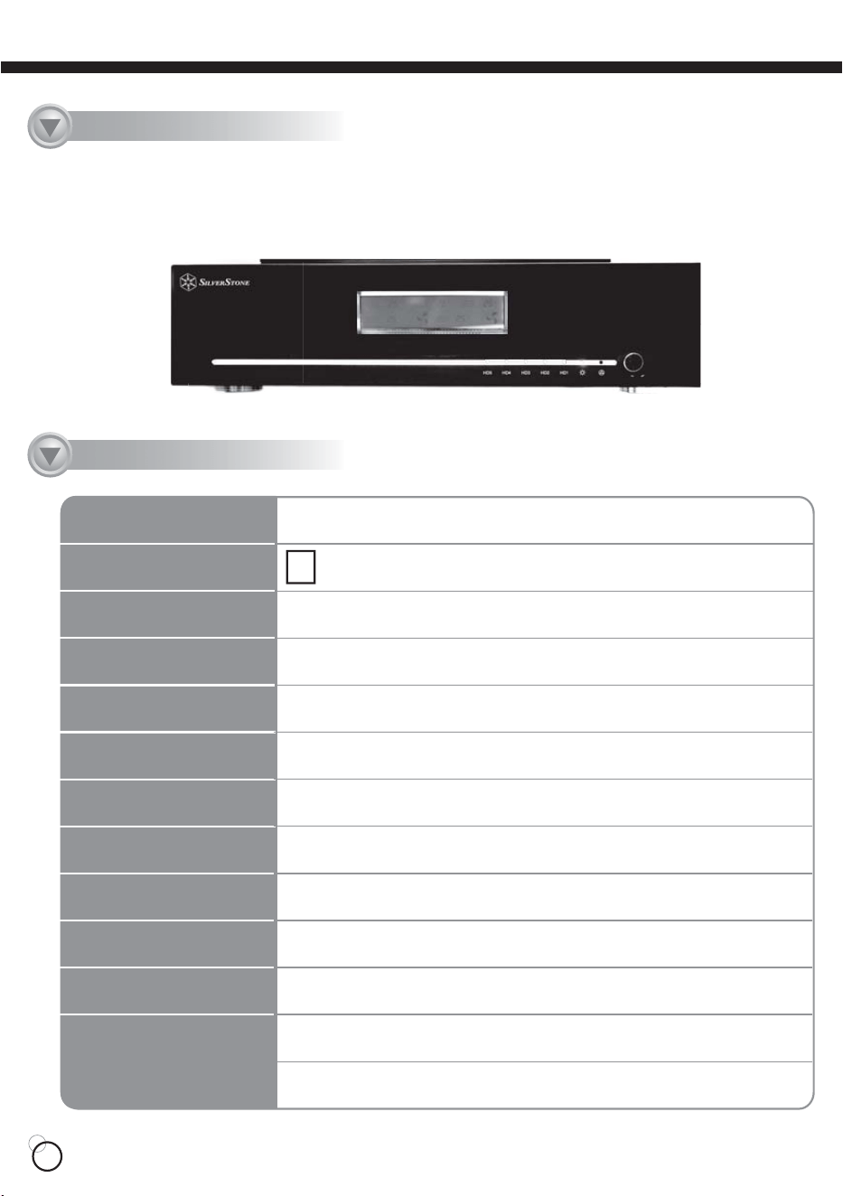
DS351
Specification
Enclosure
Color
Dimension
Power Supply
Cooling system
System Fan
Driver Size Support
Driver interface support
Enclosure interface
Chipset
RAID Level Modes
OS Support
Aluminum
Black
429mm (W) x 98mm (H) x 376mm (D)
300W SFX PSU Included
Passive Aluminum Fin
Optional 80mm fan x 2
3.5" x 5
SATA
E-SATA with Sil3132 Chipset
Silicon Image Sil4726
Raid 0 ,Raid 1 , Raid 10,Raid 5 (Raid Only Support on Windows)
Windows XP, 2000, 2003, and Mac OS 10.3/10.4,
and Linux RedHat, Fedora, SuSE 9.0 or later
Product Overview
01
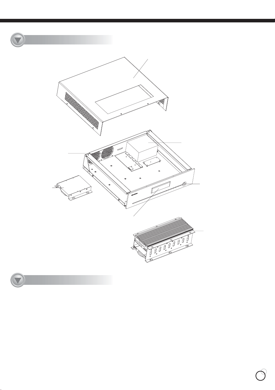
Top Panel
One Hard disk
8025 / 8015Fan (Option)
300W SFX Power Supply
Power Sw
Thermal Front Panel
Heatsink With 3.5" Hard disk X 4
D
isassemble Chart
02
Introduction
ŅŔĴĶIJ
ŅŔĴĶIJ
ŅŔĴĶIJ
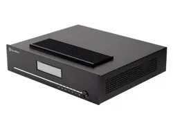
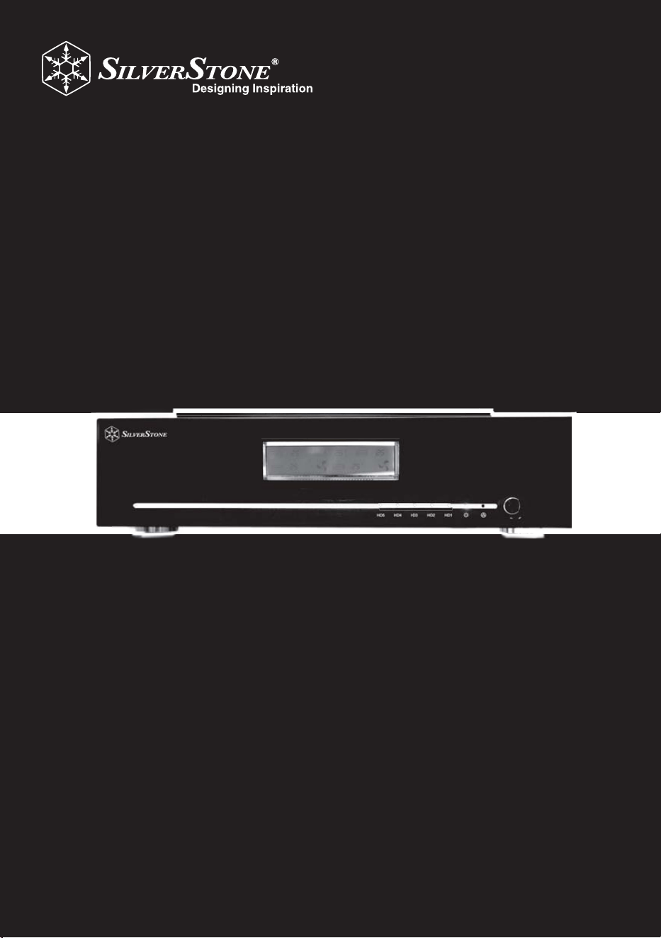
For the most ardent computer users and home theater enthusiasts that require extra data
storage space with performance to match, SilverStone created the DS351. This beautifully
crafted aluminum enclosure can house up to five SATA hard drives and has the capability
to control all drives through excellent performing RAID 5 solution. To ensure that the
DS351 not only look the part in a home theater environment, the enclosure is designed to
cool installed hard drives in either completely passive mode or with low noise fans
(enclosure fans sold separately). Powering the hard drives is a silent 300W power supply
that was handpicked to provide stable power output and reliable service. The DS351's
outstanding combination of function and style will be a great addition to anyone looking for
the perfect external storage solution.
T
his is a unique product, please read the following detailed
installation guide we have prepared meticulously for you.
03
ņŏňōŊŔʼn
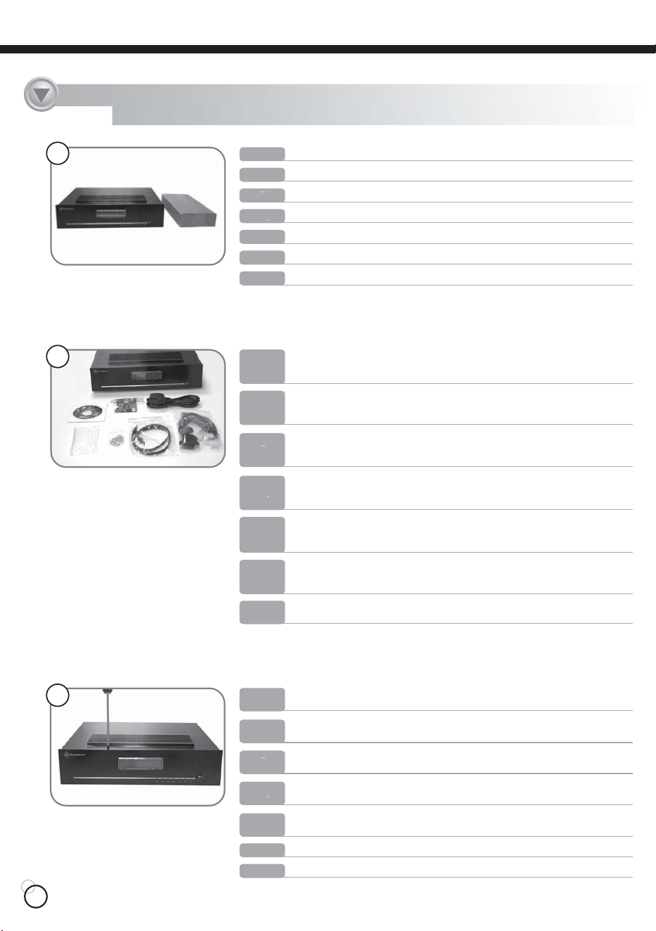
Take DS351 and accessory packet out of the box.
ŅņŖŕŔńʼn
Bitte nehmen Sie das DS351 und die Zubehörschachtel aus dem Karton.
ņŔőłŏŐō
Saque de la caja el DS351 y el paquete de los accesorios.
ŇœłŏńłŊŔ
Sortez le DS351 et le sachet d’accessoire de l’emballage.
ŊŕłōŊłŏŐ
Estrarre il DS351 ed il pacchetto degli accessori dalla scatola.
Рġҏġᇭ
DS351߅ࠃ߮ࠕࠢࠨࡄ࠶ࠢࠍ▫߆ࠄขࠅߒ߹ߔޕ
ϛȁġġМ
ி౽ϛڥюᐠ෦ЅႭӇ౽Ȅġġġġġġġġġġġġ
ıIJ
ņŏňōŊŔʼn
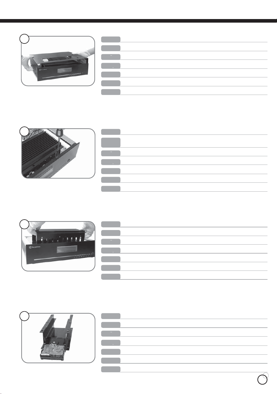
Take out the contents of accessory packet and make sure there is a, manual,
CD, PCIE to E-SATA card, SATA cable x 5pcs, Power cord, screw packet, and
cable management bands.
ŅņŖŕŔńʼn
Entnehmen Sie den Inhalt des Zubehörpaketes und vergewissern Sie sich,
dass es folgende Teile beinhaltet: Anleitung, CD, PCIE zu E-SATA Karte, SATA
Kabel x 5, Stromkabel, Schraubenset und Kabelbinder.
ņŔőłŏŐō
Saque el contenido del paquete de los accesorios y asegurese de que sea
completo: Manual, CD, tarjeta PCIE a E-SATA, cable SATA x 5pcs, Cable de
alimentación, paquete con los tornillos, y cinta para la gestión de los cables.
ŇœłŏńłŊŔ
Sortez le contenu du sachet d’accessoires et vérifiez bien qu’il contient, un
manuel, un CD, une carte PCIE vers E-SATA, 5 câbles SATA, un cordon
d’alimentation, un sachet de vis, et des bandes de gestion de câbles.
ŊŕłōŊłŏŐ
Estrarre il contenuto del pacchetto degli accessori ed assicurarsi che vi
siano: il manuale, CD, PCIE a E-SATA card, cavo SATA x 5pcs, cavo
d’alimentazione, pacchetto delle viti e fascia per la gestione dei cavi
Рġҏġᇭ
ࠕࠢࠨࡄ࠶ࠢߩౝኈࠍขࠅߒޔߦࡑ࠾ࡘࠕ࡞ޔCDޔPCIE-E-SATA
ࠞ࠼ޔSATAࠤࡉ࡞5ᧄޔ㔚Ḯࠦ࠼ޔࡀࠫߩࡄ࠶ࠢޔࠤࡉ࡞⚿᧤ࡃ
ࡦ࠼߇ߞߡࠆߎߣࠍ⏕ߒ߹ߔޕ
ϛȁġġМ
҈ႭӇ౽֏ѓ֤ᇳ݂ȃᇳ݂ӎᆅаȃőńŊņᙽņĮŔłŕłυњȃŔłŕłጣřĶ
ȃņĮŔłŕłጣȃőŐŘņœġńŐœņȃᖳ๛ѓȃႫጣጣளȄ
ıij
ņŏňōŊŔʼn
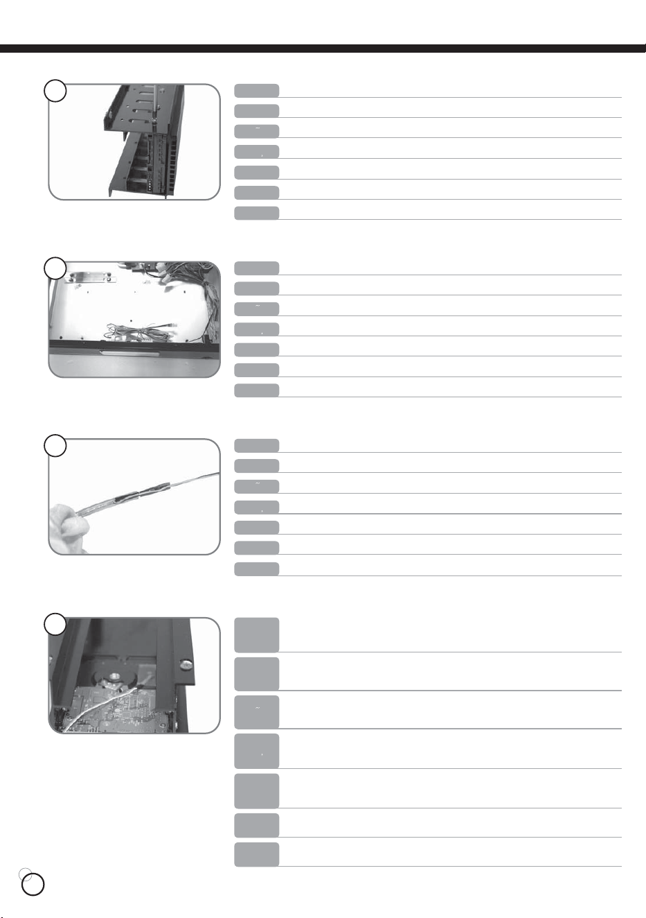
Loosen total 9 screws: two on the top panel, four on the left and right side, and
three on the back.
ŅņŖŕŔńʼn
Lösen Sie die insgesamt 9 Schrauben: zwei am Deckel, vier an der linken und
rechten Seite und drei Schrauben an der Rückseite.
ņŔőłŏŐō
Afloje 9 tornillos: 2 del panel superior, 4 de los paneles laderos derecho y
izquierdo y 3 del panel trasero.
ŇœłŏńłŊŔ
Desserrez les 9 vis: deux sur le panneau supérieur, quatre sur les côtés droit et
gauche, et trois à l’arrière.
ŊŕłōŊłŏŐ
Svitare 9 viti: 2 dal pannello superiore, quattro dai lati (destro e sinistro) e tre
dal lato posteriore.
Рġҏġᇭ
ࡀࠫ9ᧄࠍᄖߒ߹ߔޕ2ᧄߪㇱࡄࡀ࡞ޔ4ᧄߪᏀฝ㕙ޔ3ᧄߪᓟㇱߦࠅ߹ߔޕ
ϛȁġġМ
҈ΰᇐΰijᗻᖳ๛ЅѾѡڍĵᗻЅࡣĴᗻӓĺᗻᖳ๛Ȅ
ıĴ
04
ıĶ
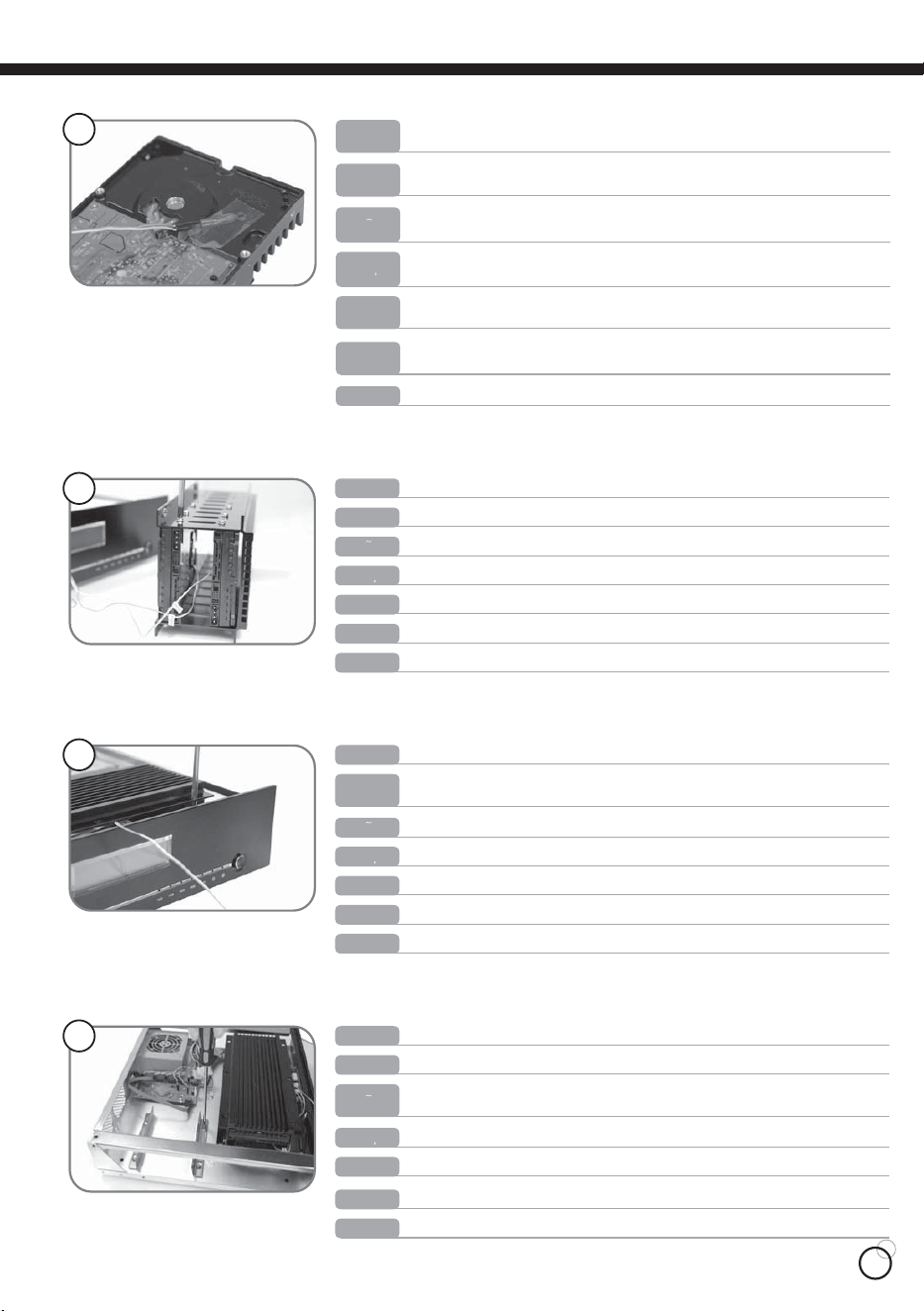
Lift to take out hard disk bracket.
ņŏňōŊŔʼn
Heben Sie den Festplattenkäfig zum herausnehmen an.
ŅņŖŕŔńʼn
Levante para quitar la abrazadera del disco duro
ņŔőłŏŐō
Soulevez le casier à disques durs pour le sortir.
ŇœłŏńłŊŔ
Sollevare ed estrarre il supporto dell’hard disk
ŊŕłōŊłŏŐ
ࡂ࠼࠺ࠖࠬࠢࡉࠤ࠶࠻ࠍขࠅߒ߹ߔޕ
Рġҏġᇭ
өΰ༖ڥюᆅ࢜Ȅ
ϛȁġġМ
ıķ
Install hard disk into the bracket.
ņŏňōŊŔʼn
Installieren Sie die Festplatten in den Festplattenkäfig.
ŅņŖŕŔńʼn
Instale el disco duro en al abrazadera.
ņŔőłŏŐō
Installez le ou les disques durs dans le casier.
ŇœłŏńłŊŔ
Installare l’hard disk nel supporto
ŊŕłōŊłŏŐ
ࡂ࠼࠺ࠖࠬࠢࠍࡉࠤ࠶࠻ߦขࠅઃߌ߹ߔޕ
Рġҏġᇭ
ᆅ၆Σᆅ࢜ϛȄ
ϛȁġġМ
ıĸ
ņŏňōŊŔʼn
The top panel then can be taken off easily.
ŅņŖŕŔńʼn
Danach lässt sich der Deckel einfach abnehmen.
ņŔőłŏŐō
El panel superior se puede quitar fácilmente
ŇœłŏńłŊŔ
Le panneau supérieur peut être retiré facilement.
ŊŕłōŊłŏŐ
Il pannello superiore può essere estratto facilmente.
Рġҏġᇭ
ߎࠇߢㇱࡄࡀ࡞ߪ◲නߦᄖࠇ߹ߔޕ
ϛȁġġМ
༖өΰΰᇐ҈Ȅ
ıĵ
ŅŔĴĶIJ
ŅŔĴĶIJ
ŅŔĴĶIJ
ņŏňōŊŔʼn
ŅņŖŕŔńʼn
ņŔőłŏŐō
ŇœłŏńłŊŔ
ŊŕłōŊłŏŐ
Рġҏġᇭ
ϛȁġġМ
Loosen the 6 screws on the hard disk bracket and remove the screws.
Lösen Sie nun die 6 Schrauben des Festplattenkäfigs, Nehmen Sie Schrauben
hervor.
Afloje 6 tornillos de la abrazadera del disco duro y Saque los tornillos.
Desserrez les 6 vis du casier à disques durs, sortez les vis.
Svitare le 6 viti dal supporto dell’hard disk estrarre il viti.
ࡂ࠼࠺ࠖࠬࠢࡉࠤ࠶࠻ߩࡀࠫ6ᧄࠍᄖߒ߹ߔ, ขߒ߹ߔߩࡀࠫ.
ᆅ࢜ķᗻᖳ๛ᚬٮиюᖳ๛
05
Remove the protective layer from the temperature sensor.
ņŏňōŊŔʼn
Ziehen Sie die Schutzhülle vom Temperatursensor.
ŅņŖŕŔńʼn
Quite la capa protectiva del sensor térmico
ņŔőłŏŐō
Retirez la couche protectrice des sondes thermiques.
ŇœłŏńłŊŔ
Rimuovere lo strato protettivo dal sensore termico.
ŊŕłōŊłŏŐ
ᐲࡦࠨ߆ࠄ⼔ࡈࠖ࡞ࡓࠍߪ߇ߒ߹ߔޕ
Рġҏġᇭ
ಋଶกྣᓞޟ߳៖ৈȄ
ϛȁġġМ
IJı
ņŏňōŊŔʼn
ŅņŖŕŔńʼn
ņŔőłŏŐō
ŇœłŏńłŊŔ
ŊŕłōŊłŏŐ
Рġҏġᇭ
ϛȁġġМ
Use a piece of tape and tape the tip of the temperature sensor to the surface of
the hard disk (Caution! Do not tape the temperature sensor to the circuit board
or on the chip itself)
Benutzen Sie ein Stück Klebeband und kleben Sie den Temperatursensor auf
die Oberfläche der Festplatte.(Achtung! Kleben Sie den Temperatursensor nicht
auf die Festplattenplatine oder den Chipsatz)
Utilize una pieza de cinta adhesiva para pegar la punta del sensor sobre la
superficie del disco duro (Advertencia: No pegue la cinta en la parte de la placa
del circuito o del chip mismo)
Utilisez un morceau d’autocollant et coller le bout de la sonde thermique sur
la surface du disque dur (Attention! Ne collez pas la sonde thermique au
circuit imprimé ou sur une puce)
Utilizzare del nastro adesivo per incollare l’estremità del sensore sulla superfice
dell’hard disk(attenzione! Non incollare il nastro adesivo intorno alla scheda del
circuito o sul chip stesso)
࠹ࡊߢᐲࡦࠨߩ┵ࠍࡂ࠼࠺ࠖࠬࠢߦ࿕ቯߒ߹ߔޕ(ߏᵈᗧ! ᐲࡦ
ࠨߪ࿁〝ၮ᧼߿࠴࠶ࡊߦ⋥ធ࿕ቯߒߥߢߊߛߐޕ
กྣᓞҢጲளᘇຮՍᆅޟᆅዺΰ(ݧཎ!ϚџกྣᓞຮՍႫၯݖΰܖ
ᆅවаΰ)Ȅ
IJIJ
Tighten and secure the hard disk in the bracket.
ņŏňōŊŔʼn
Schrauben Sie die Festplatten fest in den Käfig.
ŅņŖŕŔńʼn
Sujete el disco duro en la barazadera con los tornillos
ņŔőłŏŐō
ŇœłŏńłŊŔ
Serrez et fixez le disque dur dans le casier.
ŊŕłōŊłŏŐ
Stringere e fissare l’hard disk nel supporto.
Рġҏġᇭ
ࡂ࠼࠺ࠖࠬࠢࠍࡉࠤ࠶࠻ߦ⏕ታߦ࿕ቯߒ߹ߔޕ
ϛȁġġМ
ᆅᚇ៖Սᆅ࢜ΰȄ
ıĹ
ņŏňōŊŔʼn
Take out the temperature sensor behind the front panel.
ŅņŖŕŔńʼn
Nehmen Sie den Temperatursensor hinter der Frontblende hervor.
ņŔőłŏŐō
Saque el sensor térmico de la parte trasera del panel frontal
ŇœłŏńłŊŔ
Sortez les sondes thermiques du panneau frontal.
ŊŕłōŊłŏŐ
Estrarre il sensore termico dalla parte posteriore del pannello frontale
Рġҏġᇭ
ࡈࡠࡦ࠻ࡄࡀ࡞ⵣߩᐲࡦࠨࠍขࠅߒ߹ߔޕ
ϛȁġġМ
ࠉݖࡣПޟกྣᓞڥюȄ
ıĺ
06
ņŏňōŊŔʼn
After installing all 4 hard disks, install the bracket in the chassis.
ŅņŖŕŔńʼn
Nachdem Sie alle gewünschten Festplatten installiert haben, fügen Sie den
Festplattenkäfig wieder in das Gehäuse und schrauben Sie ihn fest.
ņŔőłŏŐō
Después de instalar los 4 discos duros, reinstale la abrazadera en el chasis
ŇœłŏńłŊŔ
Après avoir installé les 4 disques durs, remettez le casier dans le boîtier.
ŊŕłōŊłŏŐ
Dopo aver installato 4 hard disk, installare il supporto nel chassis
Рġҏġᇭ
ࡂ࠼࠺ࠖࠬࠢ4บࠍขࠅઃߌߚࠄޔࡉࠤ࠶࠻ࠍࠪࡖࠪߦᚯߒ߹ߔޕ
ϛȁġġМ
ٷו4ᗻᆅ၆ԁࡣȂӔᆅ࢜၆Սᐠ෦ΰȄ
IJĵ
ņŏňōŊŔʼn
Loosen and take out the hard disk bracket located in the rear of the chassis.
ŅņŖŕŔńʼn
Nehmen Si nun den Festplattenkäfig an der Rückseite des Gehäuses heraus.
ņŔőłŏŐō
Afloje los tornillos y saque la abrazadera del disco duro que se encuentra en la
parte trasera del chasis
ŇœłŏńłŊŔ
Desserrez et sortez le casier à disque dur situé à l’arrière du boîtier.
ŊŕłōŊłŏŐ
Estrarre il supporto dell’hard disk situato nella parte posteriore del chassis
Рġҏġᇭ
ࠪࡖࠪᓟㇱߦࠆࡂ࠼࠺ࠖࠬࠢࡉࠤ࠶࠻ࠍᄖߒޔขࠅߒ߹ߔޕ
ϛȁġġМ
ᚬࡣПᆅԊ၆࢜Ȅ
IJĶ
ņŏňōŊŔʼn
First tape the tip of temperature sensor to the hard disk before installing second
hard disk as shown.
ŅņŖŕŔńʼn
Kleben Sie den nächsten Temperatursensor erst auf die nächste Festplatte,
bevor Sie diese installieren.
ņŔőłŏŐō
Pegue la punta del sensor térmico sobre el disco duro antes de instalar el
segundo disco duro
ŇœłŏńłŊŔ
Commencez par coller le bout de la sonde thermique au disque dur avant
d’installer le second disque dur comme montré.
ŊŕłōŊłŏŐ
Incollare con il nastro adesivo il sensore termico all’hard disk prima d’installare
il secondo hard disk, come mostrato
Рġҏġᇭ
2บ⋡ߩࡂ࠼࠺ࠖࠬࠢࠍขࠅઃߌࠆ೨ߦޔ࿑ߩࠃ߁ߦᐲࡦࠨߩ┵ࠍࡂ
࠼࠺ࠖࠬࠢߦ࠹ࡊߢ࿕ቯߒ߹ߔޕ
ϛȁġġМ
Ԋ၆ήП2ᗻᆅࠉӑกྣᓞຮΰՍᆅȄ
IJij
ņŏňōŊŔʼn
Install the hard disk in the bracket.
ŅņŖŕŔńʼn
Installieren Sie die Festplatte in den Käfig.
ņŔőłŏŐō
Instale el disco duro en la abrazadera
ŇœłŏńłŊŔ
Installez le disque dur dans le casier.
ŊŕłōŊłŏŐ
Installare l’hard disk nel supporto
Рġҏġᇭ
ࡂ࠼࠺ࠖࠬࠢࠍࡉࠤ࠶࠻ߦขࠅઃߌ߹ߔޕ
ϛȁġġМ
ӵᆅ၆ΰᆅ࢜Ȅ
IJĴ
ŅŔĴĶIJ
ŅŔĴĶIJ
ŅŔĴĶIJ
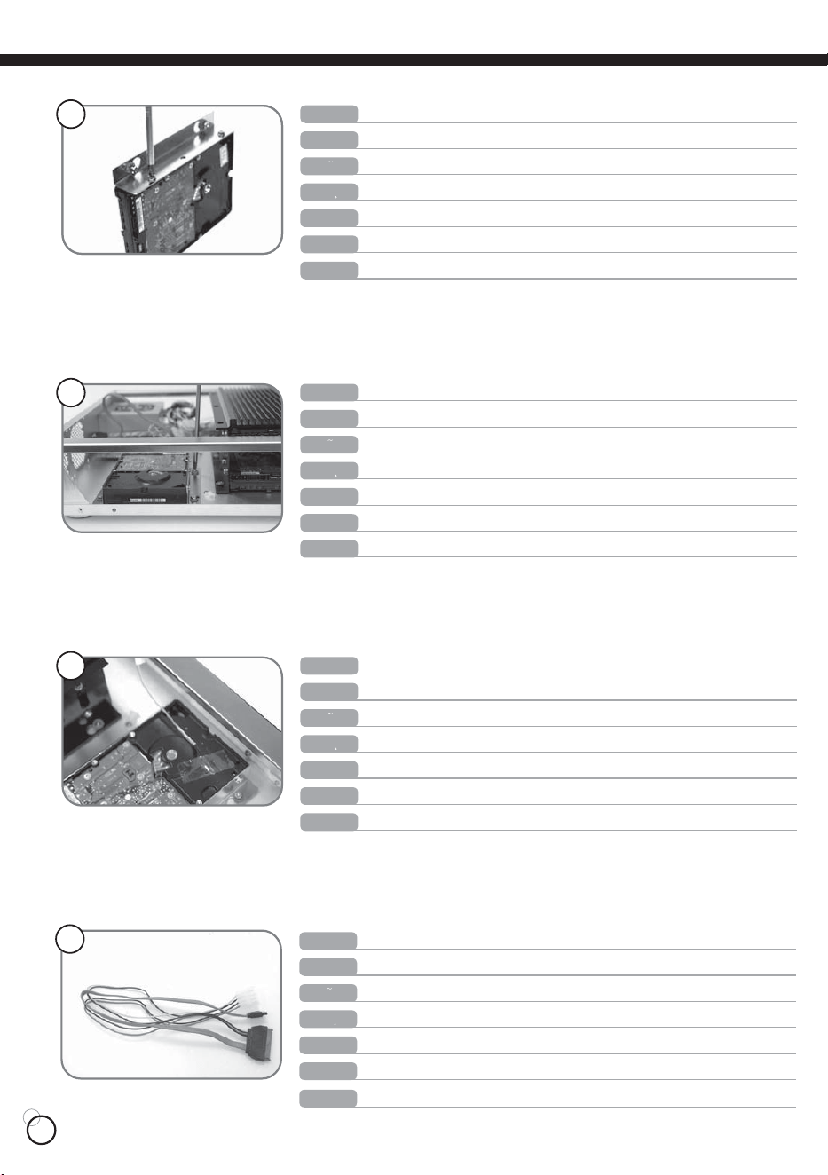
07
ņŏňōŊŔʼn
Take out the SATA power cord from the accessory pack.
ŅņŖŕŔńʼn
Entnehmen Sie den SATA Stromstecker aus dem Zubehörpaket.
ņŔőłŏŐō
Saque el cable de alimentación SATA del paquete de los accesorios
ŇœłŏńłŊŔ
Sortez le cordon d’alimentation SATA du sachet d’accessoires.
ŊŕłōŊłŏŐ
Estrarre il cavo d’alimentazione SATA dal pacchetto degli accessori.
Рġҏġᇭ
SATAࠤࡉ࡞ߣ㔚Ḯࠦ࠼ࠍࠕࠢࠨࡄ࠶ࠢ߆ࠄขࠅߒ߹ߔޕ
ϛȁġġМ
ڥюႭӇѓ၇ޟSATAႫྛጣȄ
IJĺ
ņŏňōŊŔʼn
Fasten and secure the hard disk on the bracket.
ŅņŖŕŔńʼn
Befestigen Sie die Festplatte im Käfig.
ņŔőłŏŐō
Sujete el disco duro en la abrazadera
ŇœłŏńłŊŔ
Serrez et fixez le disque dur dans le casier.
ŊŕłōŊłŏŐ
Stringere e fissare l’hard disk sul supporto.
Рġҏġᇭ
ࡂ࠼࠺ࠖࠬࠢࠍࡉࠤ࠶࠻ߦߒߞ߆ࠅ࿕ቯߒ߹ߔޕ
ϛȁġġМ
ᆅᚇ៖ӵԊ၆࢜ΰȄ
IJķ
ņŏňōŊŔʼn
Then place and secure the bracket with hard disk installed in the chassis.
ŅņŖŕŔńʼn
Platzieren Sie den Festplattenkäfig wieder im Gehäuse und schrauben Sie ihn fest.
ņŔőłŏŐō
Coloque y sujete la abrazadera con el disco duro instalado en el chasis
ŇœłŏńłŊŔ
Puis mettez et fixez le casier avec les disques durs installés dans le boîtier.
ŊŕłōŊłŏŐ
Quindi collocare e fissare il supporto con l’hard disk installato nel chassis
Рġҏġᇭ
ߘߒߡࡂ࠼࠺ࠖࠬࠢࠍⵝ⌕ߒߚࡉࠤ࠶࠻ࠍࠪࡖࠪߦ࿕ቯߒ߹ߔޕ
ϛȁġġМ
ᚇ៖ԁᆅӵᚇ៖ӵᐠ෦ΰȄ
IJĸ
ņŏňōŊŔʼn
Again place the tip of temperature sensor on the hard disk.
ŅņŖŕŔńʼn
Kleben Sie einen Temperatursensor auf die Festplatte.
ņŔőłŏŐō
Pegue la punta del sensor térmico sobre el disco duro.
ŇœłŏńłŊŔ
Une nouvelle fois placez le bout de la sonde thermique sur le disque dur.
ŊŕłōŊłŏŐ
Collocare di nuovo l’estremità del sensore termico sull’hard disk
Рġҏġᇭ
ౣᐲࡂ࠼࠺ࠖࠬࠢߦᐲࡦࠨߩ┵ࠍ࿕ቯߒ߹ߔޕ
ϛȁġġМ
ΙኺӔกྣᓞՍᆅΰȄ
IJĹ
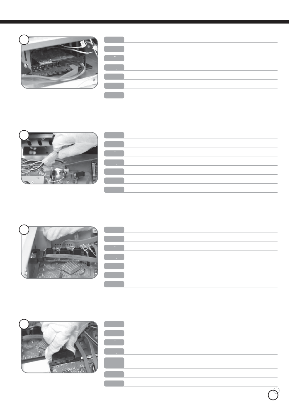
08
ņŏňōŊŔʼn
Connect the end with SATA and power cord to the hard disk.
ŅņŖŕŔńʼn
Schließen Sie das Ende mit dem SATA und Stromanschluss an die Festplatte.
ņŔőłŏŐō
Conecte una extremidad del cable con el disco duro
ŇœłŏńłŊŔ
Branchez l’extrémité du cordon d’alimentation SATA sur le disque dur.
ŊŕłōŊłŏŐ
Collegare l’estremità del cavo SATA all’hard disk
Рġҏġᇭ
SATAࠤࡉ࡞ߣ㔚Ḯࠦ࠼ߩ┵ࠍࡂ࠼࠺ࠖࠬࠢߦធ⛯ߒ߹ߔޕ
ϛȁġġМ
SATAёႫྛጣޟᆅᆒඨՍᆅΰȄ
ijı
Connect the power cord end to the power supply.
ņŏňōŊŔʼn
Schließen Sie den Stromanschluss an das Netzteil an.
ŅņŖŕŔńʼn
Conecte una extremidad con la fuente de alimentación
ņŔőłŏŐō
Branchez l’autre extrémité du cordon d’alimentation à l’alimentation.
ŇœłŏńłŊŔ
Collegare l’estremità del cavo d’alimentazione all’alimentatore
ŊŕłōŊłŏŐ
㔚Ḯࠦ࠼ߩ┵ࠍ㔚Ḯߦធ⛯ߒ߹ߔޕ
Рġҏġᇭ
ႫྛᆒՍႫྛټᔖᏢΰȄ
ϛȁġġМ
ijIJ
ņŏňōŊŔʼn
Connect the SATA cable end to the circuit board.
ŅņŖŕŔńʼn
Schließen Sie das SATA Kabel an die Platine an.
ņŔőłŏŐō
Conecte la extremidad del cable SATA con la placa de circuito
ŇœłŏńłŊŔ
Branchez le câble SATA sur le circuit imprimé.
ŊŕłōŊłŏŐ
Collegare L’estremità del cavo SATA al circuito
Рġҏġᇭ
SATAࠤࡉ࡞ߩ┵ࠍ࿁〝᧼ߦធ⛯ߒ߹ߔޕ
ϛȁġġМ
ŔłŕłᆒඨӵႫၯݖΰȄ
ijij
ņŏňōŊŔʼn
Repeat the above 3 process until all 5 hard disks are installed.
ŅņŖŕŔńʼn
Wiederholen Sie die obigen drei Schritte für alle übrigen Festplatten.
ņŔőłŏŐō
Repite los tres últimos procesos hasta instalar los 5 discos duros
ŇœłŏńłŊŔ
Répétez les étapes 3 à 5 jusqu’à ce que les 5 disques durs soient installés.
Рġҏġᇭ
⸥3ࠬ࠹࠶ࡊࠍ➅ࠅߒߡ5บߩࡂ࠼࠺ࠖࠬࠢࠍోㇱขࠅઃߌ߹ߔޕ
ϛȁġġМ
ٷוĶᗻᆅׇԙΰוĴএଢ଼հ։џȄ
ijĴ
ŊŕłōŊłŏŐ
Ripetere i tre procedimenti di cui sopra, fino a quando tutti e 5 gli hard disk
sono installati.
ŅŔĴĶIJ
ŅŔĴĶIJ
ŅŔĴĶIJ
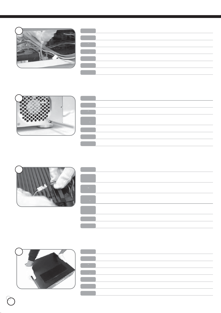
09
ņŏňōŊŔʼn
Use the cable management strap in the chassis to organize all the cables.
ŅņŖŕŔńʼn
Benutzen Sie die Kabelbinder um die Kabel im Gehäuse zu fixieren.
ņŔőłŏŐō
Use la cinta de gestión de los cables para organizar todos los cables
ŇœłŏńłŊŔ
Utilisez les attaches du boîtier pour organiser tous vos câbles.
ŊŕłōŊłŏŐ
Utilizzare la fascia di gestione dei cavi del chassis per organizzare tutti i cavi
Рġҏġᇭ
ࠪࡖࠪߦߪࠤࡉ࡞⚿᧤ࡃࡦ࠼ࠍߞߡޔࠤࡉ࡞ࠍ߈ߜࠎߣ߹ߣ߹ߔޕ
ϛȁġġМ
ᐠ෦ϱޟጣҢጣள౩ጣȄ
ijĵ
ņŏňōŊŔʼn
If you have your own 80mm cooling fans, you can install the fans as pictured.
ŅņŖŕŔńʼn
Sie können eigene 80mm Lüfter, wie auf dem Bild gezeigt, in das Gehäuse einbauen.
ņŔőłŏŐō
Si Ustd. tiene un ventilador de 80mm, puede instalarlo como se muestra
ŊŕłōŊłŏŐ
Se possiede una ventola da 80mm, la può installare come mostrato
Рġҏġᇭ
↪น⢻ߥ80mm಄ළࡈࠔࡦ߇ࠇ߫ޔ࿑ߩࠃ߁ߦขࠅઃߌ߹ߔޕ
ϛȁġġМ
ԃԤՌᗊĹϴϷٷྱყҰᚇ៖Սᐠ෦ࡣПȄ
ŇœłŏńłŊŔ
Si vous possédez vos propres ventilateurs de 80mm, vous pouvez les installer
comme illustré.
ijĶ
ņŏňōŊŔʼn
Connect the power cable from the fan to the power cable from the front panel.
ŅņŖŕŔńʼn
Zum anschließen, stecken Sie den Stromkabel des Lüfters an den 3pin
Anschluss vom Stromkabel der Frontblende.
ņŔőłŏŐō
Conecte el cable de alimentación del ventilador con el cable de alimentación
del panel frontal
ŇœłŏńłŊŔ
Branchez le câble d’alimentation du ventilateur au câble d’alimentation du
panneau frontal.
ŊŕłōŊłŏŐ
Connettere il cavo d’alimentazione dalla ventola al cavo d’alimentazione del
pannello frontale
Рġҏġᇭ
ࡈࠔࡦ߆ࠄߩ㔚Ḯࠤࡉ࡞ࠍࡈࡠࡦ࠻ࡄࡀ࡞߆ࠄߩ㔚Ḯࠤࡉ࡞ߦធ⛯ߒ߹ߔޕ
ϛȁġġМ
ႫྛՍࠉПݖޟႫྛጣΰȄ
ijķ
ņŏňōŊŔʼn
Place the top panel back on the chassis.
ŅņŖŕŔńʼn
Platzieren Sie den Deckel auf das Gehäuse.
ņŔőłŏŐō
Recoloque el panel superior sobre el chasis
ŇœłŏńłŊŔ
Remettez le panneau supérieur sur le châssis du boîtier.
ŊŕłōŊłŏŐ
Ricollocare il pannello superiore sul chassis
Рġҏġᇭ
ࠪࡖࠪߦㇱࡄࡀ࡞ࠍᚯߒ߹ߔޕ
ϛȁġġМ
ׇԙࡣΰᇐ࠭ޢ༖ᇐΰᐠ෦ΰȄ
ijĸ
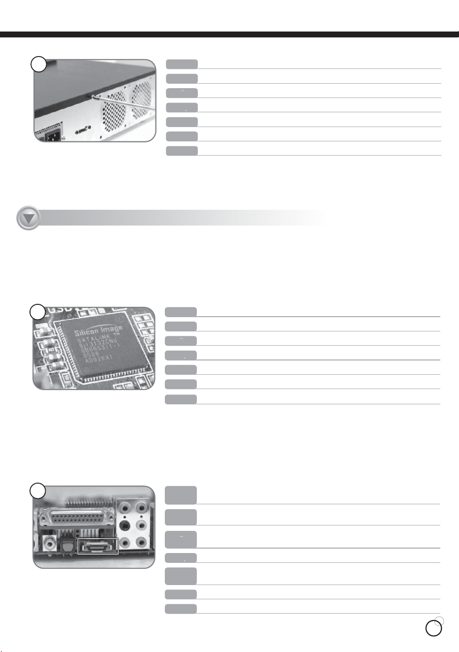
10
ņŏňōŊŔʼn
Type 1: When E-SATA motherboard uses SiI3132 chip.
ŅņŖŕŔńʼn
TYP 1: E-SATA Motherboard mit Sil3132 Chipsatz.
ņŔőłŏŐō
Tipo 1: Si la placa base E-SATA tiene chip SiI3132.
ŇœłŏńłŊŔ
Carte mère de type 1: Quand la carte mère E-SATA utilise une puce SiI3132.
ŊŕłōŊłŏŐ
Tipo 1: Se la scheda madre E-SATA utilizza il chip SiL3132
Рġҏġᇭ
࠲ࠗࡊ1: E-SATAࡑࠩࡏ࠼ߦSiI3132࠴࠶ࡊ↪ߩ႐ว
ϛȁġġМ
ŕŚőņIJġĻġԃкᐠݖņĮŔłŕłҢŔŪŊĴIJĴijවаȄ
ıIJ
ņŏňōŊŔʼn
Directly connect E-SATA connector to the E-SATA slot located behind the
motherboard.
ŅņŖŕŔńʼn
Schließen Sie den E-SATA Anschluss direkt an die E-SATA Buchse an der
Rückseite des Motherbaords.
ņŔőłŏŐō
Conecte directamente el conector E-SATA con el slot E-SATA que se encuentra
detrás de la placa base
ŇœłŏńłŊŔ
Branchez directement le câble E-SATA dans la prise E-SATA de la carte mère.
ŊŕłōŊłŏŐ
Connettere direttamente il connettore E-SATA allo slot E-SATA che si trova
dietro la scheda madre.
Рġҏġᇭ
E-SATAࠦࡀࠢ࠲ࠍ⋥ធࡑࠩࡏ࠼ᓟᣇߩE-SATAࠬࡠ࠶࠻ߦធ⛯ߒ߹ߔޕ
ϛȁġġМ
ޢņĮŔłŕłጣޢޢՍкᐠݖࡣПņĮŔłŕłඨዀȄ
ıij
Connect the DS351 to the computer
ņŏňōŊŔʼn
Tighten and secure top panel with screws.
ŅņŖŕŔńʼn
Befestigen Sie den Deckel mit Schrauben.
ņŔőłŏŐō
Sujete el panel superior con los tornillos
ŇœłŏńłŊŔ
Serrez et fixe le panneau supérieur avec des vis.
ŊŕłōŊłŏŐ
Stringere e fissare il pannello con le viti
ϛȁġġМ
ӵҢᖳ๛ΰᇐᇄᐠ෦ᚇ៖Ȅ
Рġҏġᇭ
ㇱࡄࡀ࡞ࠍࡀࠫߢ࿕ቯߒ߹ߔޕ
ijĹ
ŅŔĴĶIJ
ŅŔĴĶIJ
ŅŔĴĶIJ
11
ņŔőłŏŐō
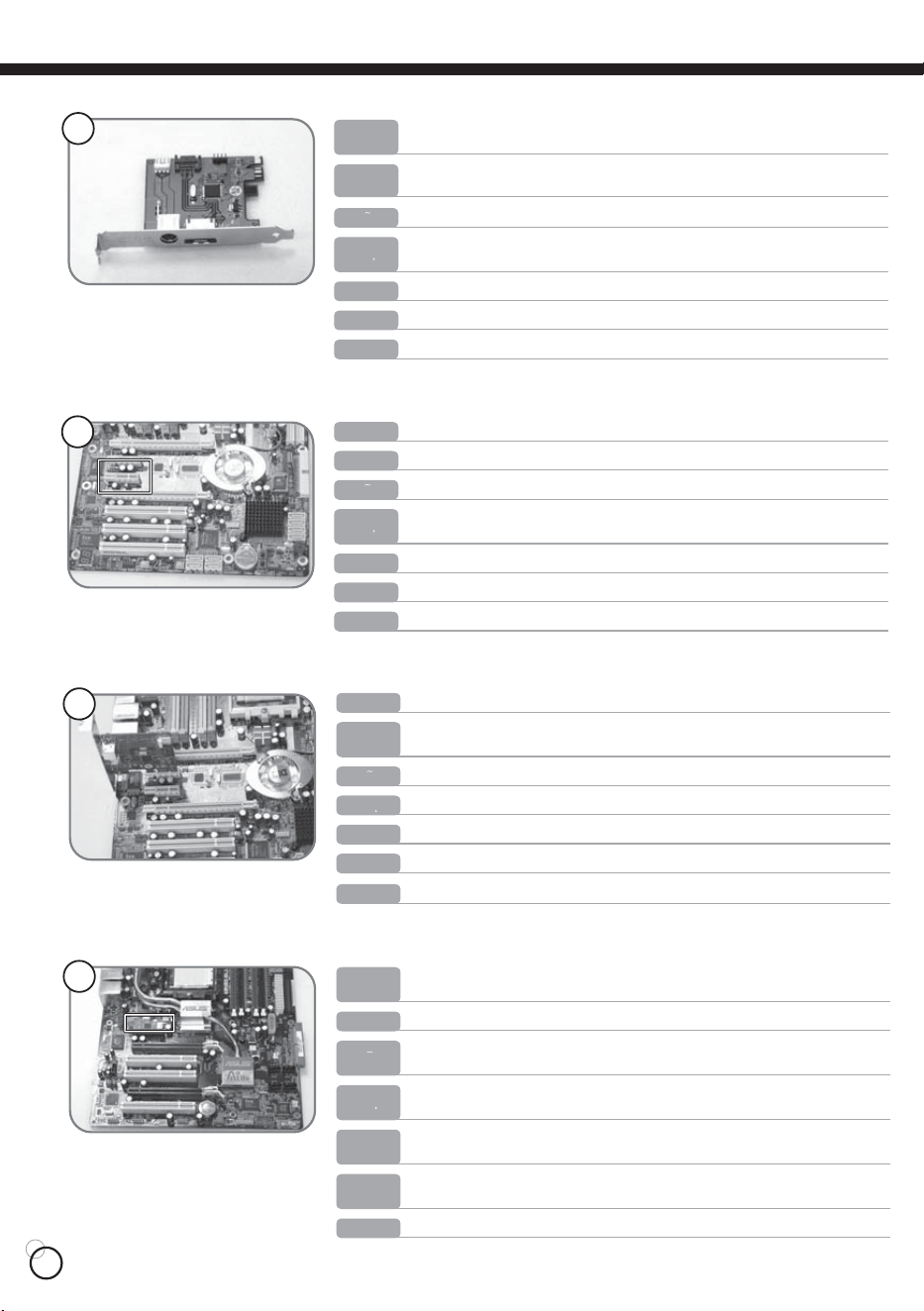
Inserte la tarjeta PCI Express en uno de los slot marcados en la foto
ņŏňōŊŔʼn
Insert the PCI Express card into one of the circled slots in the picture.
ŅņŖŕŔńʼn
Installieren Sie die PCI-Express Karte in einen, wie auf dem vorherigen Bild
markierten, freien Slot.
ŇœłŏńłŊŔ
Insérez la carte PCI Express dans l’un des emplacements entourés de la photo.
ŊŕłōŊłŏŐ
Inserire la card express PCI Express in uno degli slot evidenziati nella foto
Рġҏġᇭ
PCI Expressࠞ࠼ࠍ࿑ߢ࿐߹ࠇߚࠬࡠ࠶࠻ߩ1ߟߦᝌߒ߹ߔޕ
ϛȁġġМ
υњඨညΰყܚޟڏϛΙএඨዀȄ
ıĶ
ņŏňōŊŔʼn
Type 3 motherboard : When there is no PCI Express-X1 slot available, but
there is PCI Express-X4 available.
ŅņŖŕŔńʼn
TYP 3: Motherboard ohne freien PCI-Express X1 Slot, aber freien X4 Slots.
ņŔőłŏŐō
Placa base tipo3 : Si no hay un slot PCI Express-X1 disponible pero hay PCI
Express-X4 disponible.
ŇœłŏńłŊŔ
Carte mère de type 3 : quand il n’a pas d’emplacement PCI Express-1X
disponible, mais qu’il ya un emplacement PCI Express-4X
ŊŕłōŊłŏŐ
Scheda madre tipo 3: Se non c’é nessuno slot PCI Express-X1 disponibile ma
c’è PCI Express-X4 disponibile
Рġҏġᇭ
࠲ࠗࡊ3ࡑࠩࡏ࠼ : PCI Express-X1ࠬࡠ࠶࠻ߦⓨ߈߇ߥ߇ޔPCI Express-
X4ࠬࡠ࠶࠻߇ⓨߡࠆ႐ว
ϛȁġġМ
кᐠݖŕŚőņĴġĻġкᐠݖΰฒőńŊġņŹűųŦŴŴĮɰIJඨዀȂծԤőńŊġņŹűųŦŴŴĮɰĵџҢȄ
ıķ
ŅņŖŕŔńʼn
Sollte Ihr Motherboard keinen SiL3132 Chipsatz besitzen, so benutzen Sie bitte
die PCI Express Karte.
ņŔőłŏŐō
Saque la tarjeta PCI Express si no hay chip SiI3132 en la placa madre
ŇœłŏńłŊŔ
Si votre carte mère ne possède pas de puce SiI3132, veuillez prendre la carte
PCI Express.
ŊŕłōŊłŏŐ
Estrarre la card PCI-Express se non c‘è il chip SiI3132 sulla scheda madre
Рġҏġᇭ
ࡑࠩࡏ࠼ߦSiI3132࠴࠶ࡊ߇ߥ႐วߪPCI Expressࠞ࠼ࠍขࠅߒ߹ߔޕ
ϛȁġġМ
ԃݎкᐠݖؠԤŔŪŊĴIJĴijڥюυњȄ
ıĴ
ņŏňōŊŔʼn
Please take out the PCI Express card if there is no SiI3132 chip on your
motherboard.
ņŏňōŊŔʼn
Type 2 motherboard: When there are sufficient PCI Express-X1 slots.
ŅņŖŕŔńʼn
TYP 2: Motherboard mit ausreichenden PCI-Express X1 Slots.
ņŔőłŏŐō
Placa base tipo 2: Si hay suficientes slot PCI Express –X1
ŇœłŏńłŊŔ
Carte mère de type 2 : Quand il y a au moins un emplacement PCI Express-1X
disponible.
ŊŕłōŊłŏŐ
Scheda madre tipo 2: Se ci sono sufficienti slot PCI Express-X1.
Рġҏġᇭ
࠲ࠗࡊ2ࡑࠩࡏ࠼: PCI Express-X1ࠬࡠ࠶࠻ߦⓨ߈߇ࠆ႐ว
ϛȁġġМ
кᐠݖŕŚőņijġĻġԤٗஊޟőńŊġņŹűųŦŴŴĮɰIJඨዀȄ
ıĵ
12
ıĺ
ņŏňōŊŔʼn
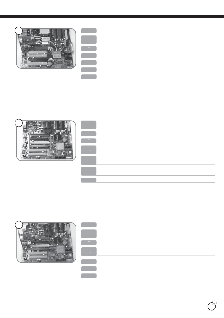
Insert the PCI Express card into one of the circled slots in the previous step.
ŅņŖŕŔńʼn
Installieren Sie die PCI-Express Karte in einen, wie auf dem vorherigen Bild
markierten, freien Slot.
ņŔőłŏŐō
Inserte la tarjeta PCI Express en uno de los slot marcados de la foto anterior
ŇœłŏńłŊŔ
Insérez la carte PCI Express dans l’un des emplacements entourés de l’image
précédente.
ŊŕłōŊłŏŐ
Inserire la card PCI Express in uno degli slot evidenziati nella foto precedente
Рġҏġᇭ
PCI Expressࠞ࠼ࠍ೨ࠬ࠹࠶ࡊߢ࿐ࠎߛࠬࡠ࠶࠻ߩ1ߟߦᝌߒ߹ߔޕ
ϛȁġġМ
υњඨΣΰყܚᒵޟڏϛΙএඨዀΰȄ
ņŏňōŊŔʼn
Install the PCI Express card on slot circled in the previous picture.
ŅņŖŕŔńʼn
Installieren Sie die PCI-Express Karte in einen, wie auf dem vorherigen Bild
markierten, freien Slot.
ņŔőłŏŐō
Instale la tarjeta PCI Express en el slot marcado de la foto anterior
ŇœłŏńłŊŔ
Installez la carte PCI Express dans l’emplacement entouré de l’image précédente.
ŊŕłōŊłŏŐ
Installare la card PCI Express nello slot evidenziati nella foto precedente
Рġҏġᇭ
PCI Expressࠞ࠼ࠍ೨ߩ࿑ߢ࿐ࠎߛࠬࡠ࠶࠻ߦᝌߒ߹ߔޕ
ϛȁġġМ
υњՍΰყܚޟყҰ՝ညȄ
ıĸ
ıĹ
ŅņŖŕŔńʼn
TYP 4: Motherboard mit freien PCI-Express X8 oder PCI-Express X16 Slots.
ņŔőłŏŐō
Placa base tipo 4: Si solo hay slot PCI Express-X8 o PCI Express-X16 disponibles.
ŇœłŏńłŊŔ
Carte mère de type 4 : Quand il n’y seulement que des emplacements PCI
Express-8X ou PCI Express-16X disponibles.
ŊŕłōŊłŏŐ
Scheda madre tipo 4: Quando ci sono, solo slot PCI Express-X8 o PCI Express-
X16 disponibili
Рġҏġᇭ
࠲ࠗࡊ4ࡑࠩࡏ࠼ : PCI Express-X8߹ߚߪPCI Express-X16ࠬࡠ࠶࠻ߒ߆
↪ߢ߈ߥ႐ว
ϛȁġġМ
кᐠݖŕŚőņĵġĻġӒഋѫԤőńŊġņŹűųŦŴŴĮɰĹܖőńŊġņŹűųŦŴŴĮɰIJķඨዀȄ
ņŏňōŊŔʼn
Type 4 motherboard : When there are only PCI Express-X8 or PCI Express-X16
slots available.
ŅŔĴĶIJ
ŅŔĴĶIJ
ŅŔĴĶIJ
13
IJIJ
ņŏňōŊŔʼn
Then connect the other end to the back of the DS351.
ŅņŖŕŔńʼn
Schließen Sie dann das andere Ende des Kabels an die Rückseite des DS351 an.
ņŔőłŏŐō
Luego conecte la otra extremidad con la parte trasera del DS351.
ŇœłŏńłŊŔ
Puis branchez l’autre extrémité à l’arrière du DS351.
ŊŕłōŊłŏŐ
Connettere l’altra estremità alla parte posteriore del DS351.
Рġҏġᇭ
ߘࠇ߆ࠄઁ┵ࠍDS351ߩᓟㇱߦធ⛯ߒ߹ߔޕ
ϛȁġġМ
ӔѪΙᆒඨՍѴ౽ࡣПȄ
IJĴ
ņŏňōŊŔʼn
Picture when power is on.
ŅņŖŕŔńʼn
Abbildung mit eingeschaltetem Power-Knopf.
ņŔőłŏŐō
Encendido
ŇœłŏńłŊŔ
Photo avec l’alimentation allumée.
Рġҏġᇭ
㔚Ḯ߇ࠝࡦߩ⁁ᘒ
ϛȁġġМ
őŐŘņœంᜰޑᄘȄ
ŊŕłōŊłŏŐ
Foto ad apparato acceso
IJij
ņŏňōŊŔʼn
Picture when power is off.
ŅņŖŕŔńʼn
Abbildung mit ausgeschaltetem Power-Knopf.
ņŔőłŏŐō
Apagado.
ŇœłŏńłŊŔ
Photo avec l’alimentation éteinte.
ŊŕłōŊłŏŐ
Foto ad apparato spento
Рġҏġᇭ
㔚Ḯ߇ࠝࡈߩ⁁ᘒ
ϛȁġġМ
őŐŘņœҐᜰޑᄘȄ
IJı
ņŏňōŊŔʼn
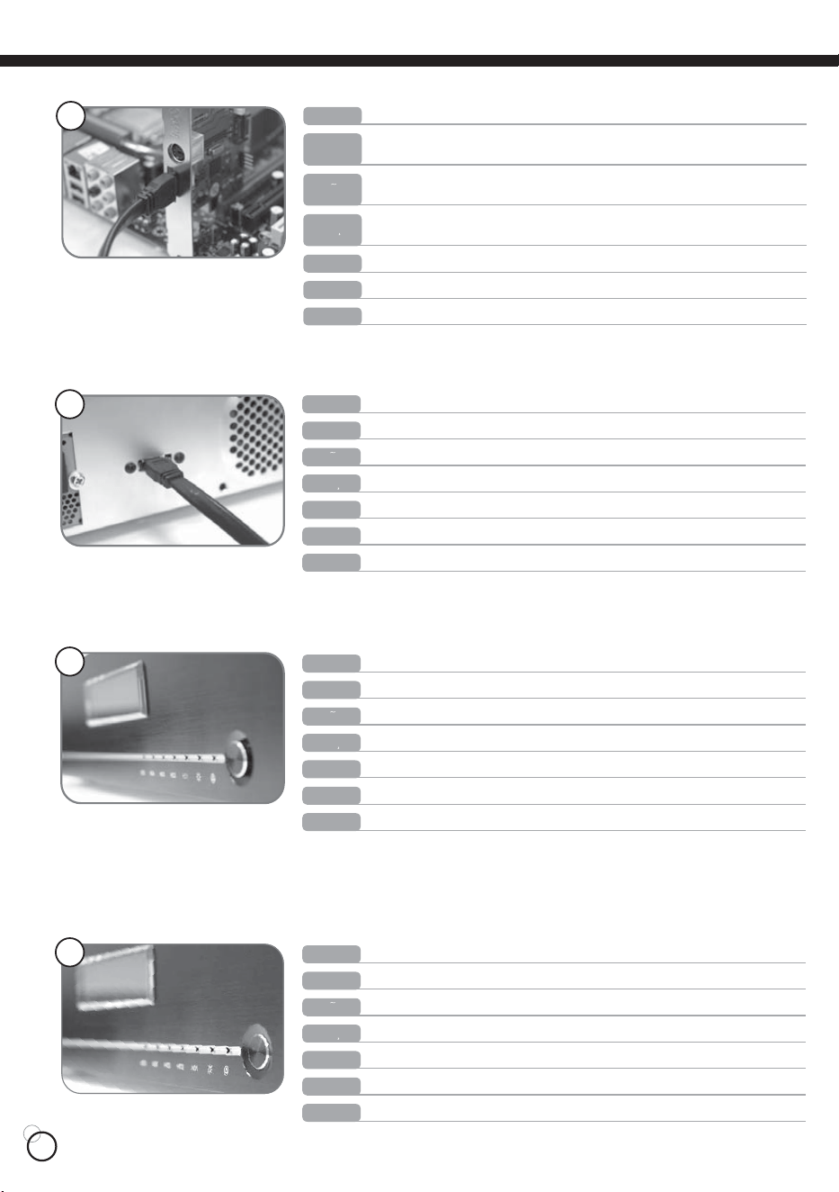
First connect one end of E-SATA connector to the E-SATA slot as pictured.
ŅņŖŕŔńʼn
Schließen Sie nun erst das Ende des E-SATA Anschlusses an die Slot-Karte,
wie auf dem Bild gezeigt.
ņŔőłŏŐō
Primero conecte una extremidad del conector E-SATA con el slot E-SATA como
se muestra
ŇœłŏńłŊŔ
Branchez d’abord une extrémité du câble E-SATA à la carte E-SATA comme
illustré.
ŊŕłōŊłŏŐ
Connettere un’estremità del connettore E-SATA allo slot E-SATA come mostrato
Рġҏġᇭ
߹ߕ࿑ߩࠃ߁ߦE-SATAࠦࡀࠢ࠲ߩ৻┵ࠍE-SATAࠬࡠ࠶࠻ߦធ⛯ߒ߹ߔޕ
ϛȁġġМ
ӑΙᆒņĮŔłŕłᓞඨՍυњࡣПޟņĮŔłŕłඨ৴Ȅ
14
D
T
W
W
Warranty Information
ŅŔĴĶIJ
ŅŔĴĶIJ
ŅŔĴĶIJ
December, 2006
NO.G11202961

