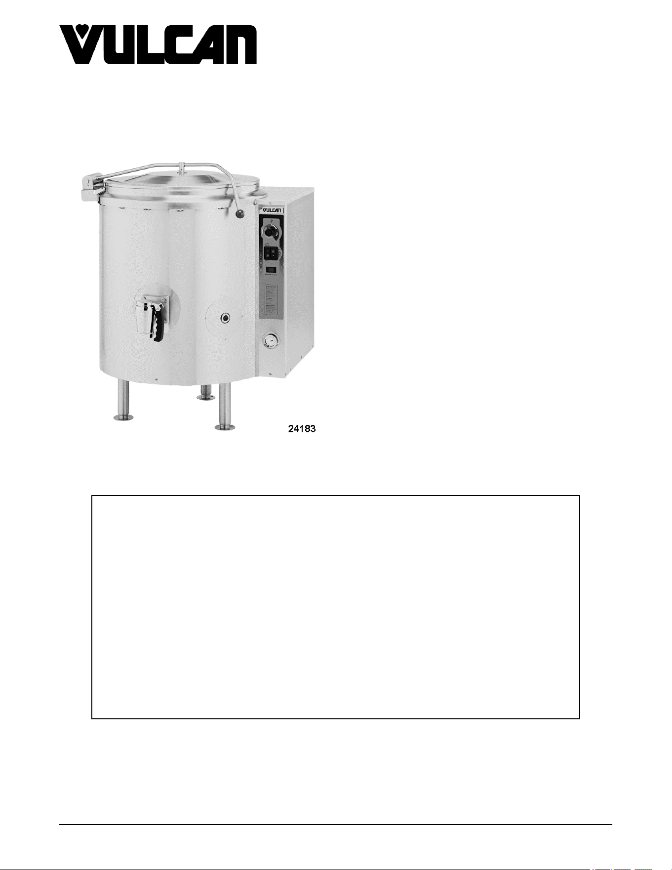
K40GL Shown
K Series Gas Kettles 2/3 Jacketed
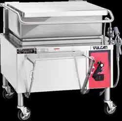
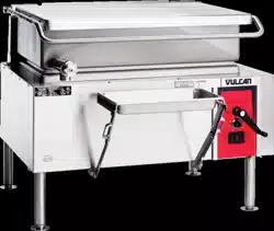
Stationary and Tilting
K20GL ML-136090
K40GL ML-136091
K60GL ML-136092
K20GLT ML-136094
K40GLT ML-136095
K60GLT ML-136096
- NOTICE -
This Manual is prepared for the use of trained Hobart Service Technicians and should not
be used by those not properly qualified.
This manual is not intended to be all encompassing. If you have not attended a Hobart Service
School for this product, you should read, in its entirety, the repair procedure you wish to
perform to determine if you have the necessary tools, instruments and skills required to
perform the procedure. Procedures for which you do not have the necessary tools,
instruments and skills should be performed by a trained Hobart Service Technician.
The reproduction, transfer, sale or other use of this manual, without the express written
consent of Hobart, is prohibited.
This manual has been provided to you by ITW Food Equipment Group LLC ("ITW FEG")
without charge and remains the property of ITW FEG, and by accepting this manual you agree
that you will return it to ITW FEG promptly upon its request for such return at any time in the
future.
SERVICE MANUAL
A product of Vulcan-Hart 3600 North Point Blvd Baltimore, MD 21222
F45461 Rev. E (0124)

TABLE OF CONTENTS
SERVICE UPDATES ....................................................................................... 4
SERVICE UPDATES ................................................................................... 4
GENERAL .................................................................................................. 5
INTRODUCTION ....................................................................................... 5
MODELS COVERED ................................................................................... 5
CONTROL PANEL ..................................................................................... 6
TOOLS ................................................................................................. 6
SPECIFICATIONS ...................................................................................... 6
OPERATION, CLEANING AND MAINTAINENCE ........................................................ 7
REMOVAL AND REPLACEMENT OF PARTS ............................................................... 8
CONTROL BOX COVER (TILTING) ..................................................................... 8
CORNER & REAR PANELS (TILTING) .................................................................. 8
SIDE & REAR PANELS (STATIONARY) ................................................................ 8
BOTTOM COVER ...................................................................................... 9
ELECTRICAL PANEL COMPONENTS .................................................................. 9
CONTROL BOX (TILTING) ......................................................................... 9
KETTLE CONTROL AREA .......................................................................... 9
PRESSURE SWITCH (1PAS) .......................................................................... 10
GAS VALVE .......................................................................................... 11
BLOWER ............................................................................................. 11
BURNER .............................................................................................. 12
SPARK IGNITOR ...................................................................................... 13
GAS SHUT-OFF VALVE (1SOL) - TILTING MODELS ONLY ............................................ 14
GEAR REDUCER - MANUAL TILTING MODELS ....................................................... 15
ELECTRICAL PANEL COMPONENTS - POWER TILTING OPTION ONLY ............................. 16
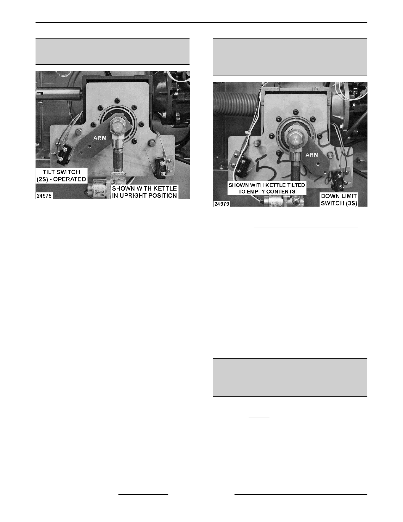
TILT SWITCH (2S) - POWER TILTING OPTION ONLY ................................................. 16
DOWN LIMIT SWITCH (3S) - POWER TILTING OPTION ONLY ........................................ 16
DC TILT MOTOR - POWER TILTING OPTION ONLY .................................................. 17
GEAR REDUCER - POWER TILTING OPTION ONLY .................................................. 17
SERVICE PROCEDURES AND ADJUSTMENTS ........................................................... 20
TEMPERATURE CONTROLLER TEST ................................................................ 20
POTENTIOMETER TEST .............................................................................. 21
THERMOCOUPLE TEST .............................................................................. 21
VENTING ............................................................................................. 22
BLOWER INLET PRESSURE CHECK ENDING AT SN 46-3028411 .................................... 23
BLOWER INLET PRESSURE CHECK 2ND GENERATION STARTING AT SN 46-3028412 ............. 23
GAS VALVE/BLOWER INLET PRESSURE CHECK (108W) ............................................ 24
TO ADJUST: ...................................................................................... 25
GAS VALVE/BLOWER INLET PRESSURE CHECK (130W) ............................................ 25
GAS VALVE/BLOWER INLET PRESSURE CHECK FOR 2ND GENERATION
STARTING AT SN 46-3028412 .................................................................... 26
TO ADJUST: ...................................................................................... 27
SPARK IGNITION TEST ............................................................................... 28
FLAME SENSE CURRENT TEST ...................................................................... 29
IGNITION CONTROL MODULE TEST ................................................................. 29
TILT SWITCH (2S) ADJUSTMENT - MANUAL TILTING MODELS ...................................... 30
KETTLE TILT ADJUSTMENT - MANUAL TILTING MODELS ........................................... 30
TILT SWITCH (2S) ADJUSTMENT - POWER TILTING OPTION ONLY ................................. 32
DOWN LIMIT SWITCH (3S) ADJUSTMENT - POWER TILTING OPTION ONLY ......................... 32
DC TILT MOTOR CONTROLLER TEST - POWER TILTING OPTION ONLY ............................ 32
SETTING RESISTOR ON CONTROLLER SPEED BOARD ............................................. 34
FILLING THE RESERVOIR JACKET ................................................................... 35
ELECTRICAL OPERATION ................................................................................ 39
K Series Gas Kettles 2/3 Jacketed Stationary and Tilting
F45461 Rev. E (0124) Page 2 of 55

COMPONENT FUNCTION (STATIONARY & TILTING MODELS) ....................................... 39
COMPONENT FUNCTION (POWER TILTING OPTION) ................................................ 40
COMPONENT LOCATION (STATIONARY & TILTING MODELS) ....................................... 41
SEQUENCE OF OPERATION (KETTLE CONTROL CIRCUIT) ......................................... 44
SEQUENCE OF OPERATION (POWER TILTING OPTION) ............................................ 46
SCHEMATIC DIAGRAM (STATIONARY & TILTING MODELS) ......................................... 48
SCHEMATIC DIAGRAM (POWER TILTING OPTION) .................................................. 50
TROUBLESHOOTING ..................................................................................... 52
STATIONARY & TILTING - GENERAL ................................................................. 52
POWER TILTING OPTION ONLY ...................................................................... 54
K Series Gas Kettles 2/3 Jacketed Stationary and Tilting
© VULCAN 2024
Page 3 of 55 F45461 Rev. E (0124)

SERVICE UPDATES
SERVICE UPDATES
January 2024
• Updated FILLING THE RESERVOIR JACKET.
December 2023
• Updated FILLING THE RESERVOIR JACKET.
• Updated TOOLS.
May 2022
• Updated TEMPERATURE CONTROLLER
TEST.
April 2022
• Update GAS VALVE/BLOWER INLET
PRESSURE CHECK FOR 2ND GENERATION
STARTING AT SN 46-3028412.
November 2020
• Update BLOWER INLET PRESSURE CHECK
2ND GENERATION STARTING AT SN
46-3028412.
September 2020
• Updated TOOLS.
• Updated SPECIFICATIONS.
• Updated ELECTRICAL PANEL
COMPONENTS.
• Updated THERMOCOUPLE TEST.
• Updated VENTING.
• Updated FILLING THE RESERVOIR JACKET.
• Added BLOWER INLET PRESSURE CHECK
2ND GENERATION STARTING AT SN
46-3028412.
• Updated STATIONARY & TILTING -
GENERAL .
• Updated STATIONARY & TILTING -
GENERAL .
October 2017
• Updated FILLING THE RESERVOIR JACKET.
• Updated GAS VALVE/BLOWER INLET
PRESSURE CHECK (108W).
K Series Gas Kettles 2/3 Jacketed Stationary and Tilting - SERVICE UPDATES
F45461 Rev. E (0124) Page 4 of 55

GENERAL
INTRODUCTION
General
The procedures in this manual apply to all models unless otherwise specified. The pictures and illustrations are of
a model K40GLT floor model tilting kettle unless otherwise noted. All information and specifications contained in
this manual are based on the latest product information available at the time of printing.
K Series - Tilting Kettles
The tilting kettles models are offered with a manual tilt mechanism as standard and are available with an optional
power tilt to automatically lower and raise the kettle. Kettles with the power tilt option can still be operated manually
using the crank handle as needed.
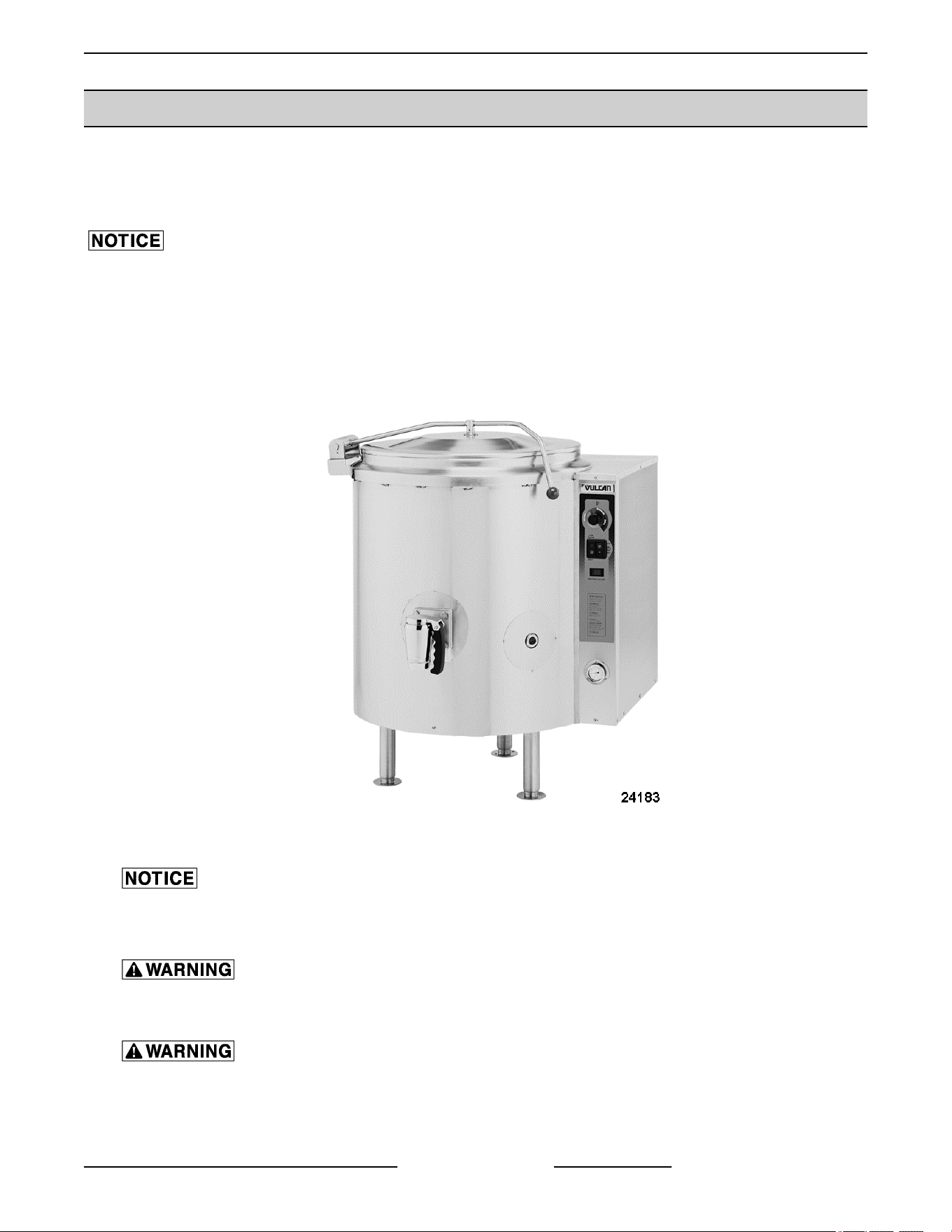
K Series - Floor Model Kettles
The 2/3 jacketed gas kettles are self contained. The lower two thirds of the kettle bowl is a double wall stainless
steel construction that provides a reservoir for a solution of heat transfer fluid and distilled water for improved heating
of the kettle contents. The kettles are used to prepare a variety of liquid or semi-liquid food products such as soups,
stews and sauces.
MODELS COVERED
All K Series kettles are mounted to the floor using legs with flanged feet for anchoring.
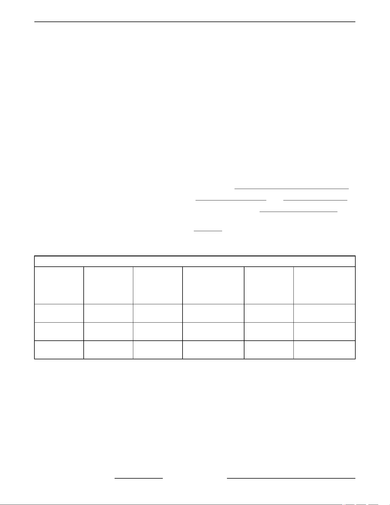
Model Type Gallons Quarts
K20GL Stationary 20 80
K40GL Stationary 40 160
K60GL Stationary 60 240
K20GLT Tilting 20 80
K40GLT Tilting 40 160
K60GLT Tilting 60 240
K Series Gas Kettles 2/3 Jacketed Stationary and Tilting - GENERAL
Page 5 of 55 F45461 Rev. E (0124)
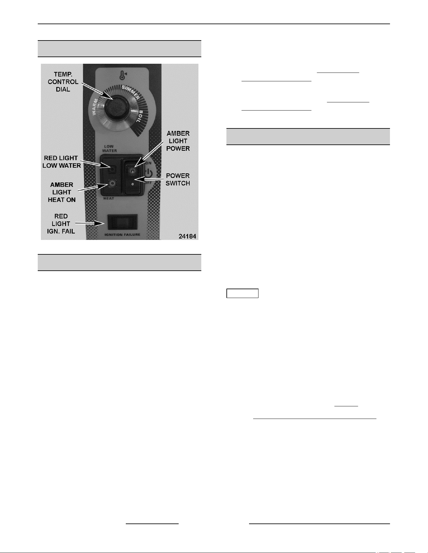
CONTROL PANEL
Fig. 1
TOOLS
Standard
• Standard set of hand tools.
• Pipe thread sealant (must be resistant to the
action of propane gases).
• VOM with an AC current tester (meter sensitivity
should be at least 20,000 ohms per volt).
• Temperature meter (thermocouple type) for
checking kettle temperature.
• Manometer capable of reading at least 16" W.C.
of gas pressure.
• Container that is capable of holding at least 8
gallons of drained reservoir jacket fluid.
Special
• Torque wrench capable of tightening combustion
chamber mountings nuts to 30 ft-lbs.
• 36mm socket to remove sight glass for jacket
fluid draining.
• Requires U-inclined (Grainger P/N 3T294) or
digital (Grainger P/N 1XFW2) manometer for
measuring gas pressures and blower air
pressures.
• Thermodyne 90395 GLYCOL, HEAT
TRANSFER FLUID, 1 GALLON, available at
Parts Town or DOWFROST™ Propylene Glycol
at ChemWorld. Refer to FILLING THE
RESERVOIR JACKET for volumes.
• Distilled water only for re-filling of the jacket
(purchase locally). Refer to FILLING THE
RESERVOIR JACKET for volumes.
• Drill Pump.
SPECIFICATIONS
Electric
• 120VAC / 60HZ / 1 phase.
• 5 amp rating.
• Supplied with 6 foot power cord and 3-prong
grounding plug (proper ground required).
NOTE: Machines with electronic ignition systems
should be connected to a standard 120VAC electrical
outlet rather than a ground fault circuit interrupter
(GFCI) if possible. Machines connected to certain
GFCI circuits may repeatedly nuisance trip the GFCI.
If the machine must be connected to a GFCI, use Part
No. 913053 (Pass and Seymour) approved by
engineering for use with electronic ignition systems.
Gas Supply
NOTICE
The gas supply pressure must not exceed 14” WC (½
PSI). Pressures higher than 14” WC will damage the
equipment’s gas controls and is not covered under
warranty. If the supply pressure exceeds 14” WC an
additional supply line regulator rated for the supply line
pressure (inches WC), nominal pressure (OUT), and
gas flow for the kettle BTU rating must be installed.
Span gas technology enables "field adjustable
manifold pressure" from natural to propane gas or
propane to natural. All kettles shipped for natural gas
at sea level atmospheric pressure. Requires a U-
Inclined or digital manometer. See TOOLS.
Refer to F35461 Installation & Operation Manual for
specific instructions on GAS CONNECTIONS and
GAS AND ALTITUDE ADJUSTMENTS. A combustion
analyzer is required for gas type conversions and
altitude adjustments as outlined in these procedures.
K Series Gas Kettles 2/3 Jacketed Stationary and Tilting - GENERAL
F45461 Rev. E (0124) Page 6 of 55

GAS SUPPLY PRESSURES
GAS TYPE Manifold (in W.C.) NOMINAL (in W.C.) MIN (in W.C.) MAX (in W.C.)
Natural
Low Speed * - 0.27 to 0.30
High Speed - 1.91 to 1.98
7 5 10.5
Propane
Low Speed * - 0.27 to 0.30
High Speed - 1.91 to 1.98
11 11 13
* Low Speed – Blower operates at low speed during trial for ignition (approximately 7 seconds). Ignition is
successful and burner lights. Blower switches to high speed for normal operation approximately 8 seconds
later (total time delay of 15 sec. to high speed) and runs until set point temperature is satisfied. Cycle
repeats upon call for heat.
Kettle Rating
All models listed on front cover have an input BTU rating of 100,000 BTU/HR.
OPERATION, CLEANING AND MAINTAINENCE
Refer to F35461 Installation & Operation Manual for specific instructions. The manual includes:
• A page from the Stainless Steel Care and Cleaning Guide for proper care and cleaning of stainless steel.
• Draw-Off Valve and Plug Valve dissassembly & cleaning instructions.
K Series Gas Kettles 2/3 Jacketed Stationary and Tilting - GENERAL
Page 7 of 55 F45461 Rev. E (0124)
REMOVAL AND REPLACEMENT OF PARTS
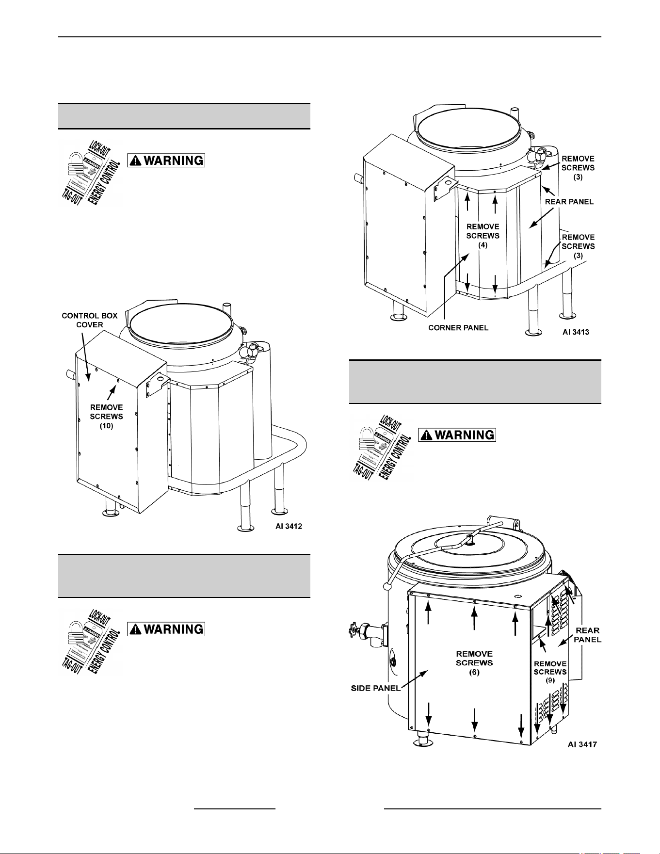
CONTROL BOX COVER (TILTING)
Disconnect the electrical power to
the machine and follow lockout /
tagout procedures.
NOTE: Remove screws from cover where indicated.
NOTE: On kettles with manual tilt or power tilt option,
the control box height is now taller (as shown) to
acomodate additional tilt components. The cover is
held in place using the same number of screws.
K20GLT Manual Tilt Shown
CORNER & REAR PANELS
(TILTING)
Disconnect the electrical power to
the machine and follow lockout /
tagout procedures.
NOTE: Remove screws from panel where indicated.
K20GLT Manual Tilt Shown
SIDE & REAR PANELS
(STATIONARY)
Disconnect the electrical power to
the machine and follow lockout /
tagout procedures.
NOTE: Remove screws from panel where indicated.
K20GL Shown
K Series Gas Kettles 2/3 Jacketed Stationary and Tilting - REMOVAL AND REPLACEMENT OF PARTS
F45461 Rev. E (0124) Page 8 of 55
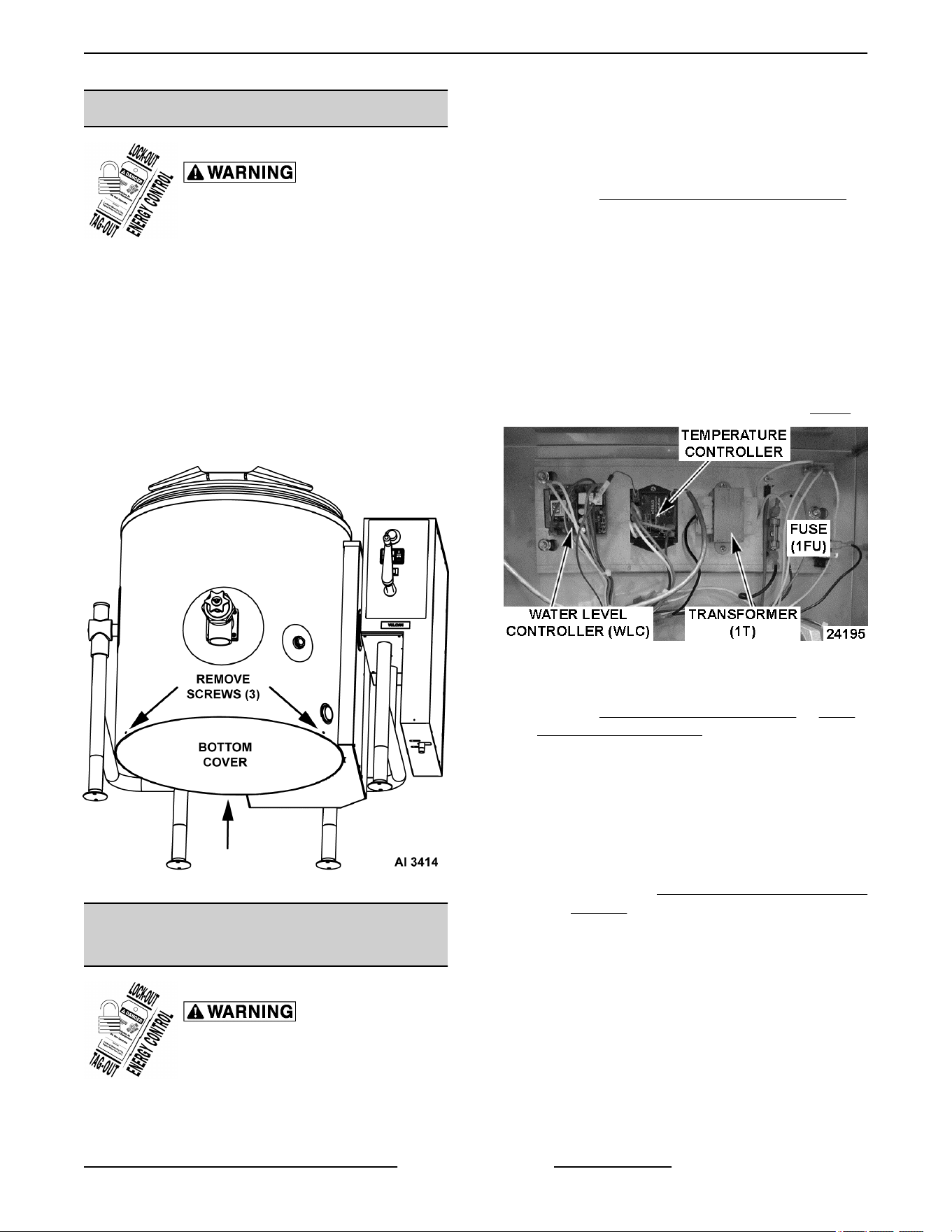
BOTTOM COVER
Disconnect the electrical power to
the machine and follow lockout /
tagout procedures.
NOTE: Remove screws from cover where indicated.
• Tilting models - tilt kettle to empty contents and
gain access to bottom components.
• Stationary models - use draw off valve to empty
contents.
• Raise the kettle for easier access to the
bottom components as necessary. Support
the kettle in some manner (2x4 blocks etc.)
while work is being performed.
K20GLT Manual Tilt Shown
ELECTRICAL PANEL
COMPONENTS
Disconnect the electrical power to
the machine and follow lockout /
tagout procedures.
NOTE: Pictures show the electrical panel
components for a tilting kettle (control box & kettle
control area). On a stationary kettle, all the electrical
panel components are mounted in the kettle control
area.
CONTROL BOX (TILTING)
1. Remove CONTROL BOX COVER (TILTING).
2. Disconnect lead wires from component being
replaced.
3. Remove screws securing the component to
panel.
4. Reverse procedure to install and check for proper
operation.
NOTE: Ensure J1 jumper is installed on temperature
controller.
Control Box - K Series Tilting Kettle (Fig. 6)
Fig. 6
KETTLE CONTROL AREA
1. Remove CORNER PANEL (TILTING) or SIDE
PANEL (STATIONARY).
2. Disconnect lead wires from component being
replaced.
3. Remove fastener securing the component to
panel.
A. If installing blower speed control, ensure
switches SW1, SW2 & SW4 are properly set
as shown in Blower Speed Control - Switch
Settings picture in this procedure.
4. Reverse procedure to install and check for proper
operation.
Kettle Control Area - K Series Tilting Kettles
K Series Gas Kettles 2/3 Jacketed Stationary and Tilting - REMOVAL AND REPLACEMENT OF PARTS
Page 9 of 55 F45461 Rev. E (0124)
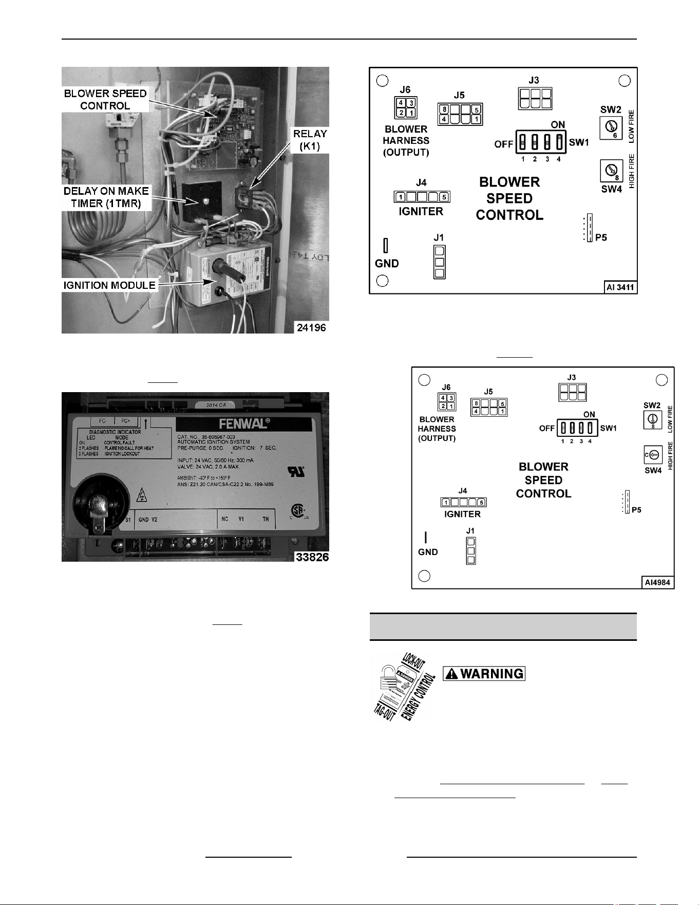
Fig. 7
2ND GENERATION IGNITION MODULE
SHOWN IN Fig. 8
Fig. 8
Blower Speed Control - Switch Settings 1st
Generation Motor (Baldor High Fire and Low
Fire Settings Shown in Fig. 9)
Fig. 9
Blower Speed Control - Switch Settings 2nd
Generation Motor (High Fire and Low Fire
Settings Shown in Fig. 10)
Fig. 10
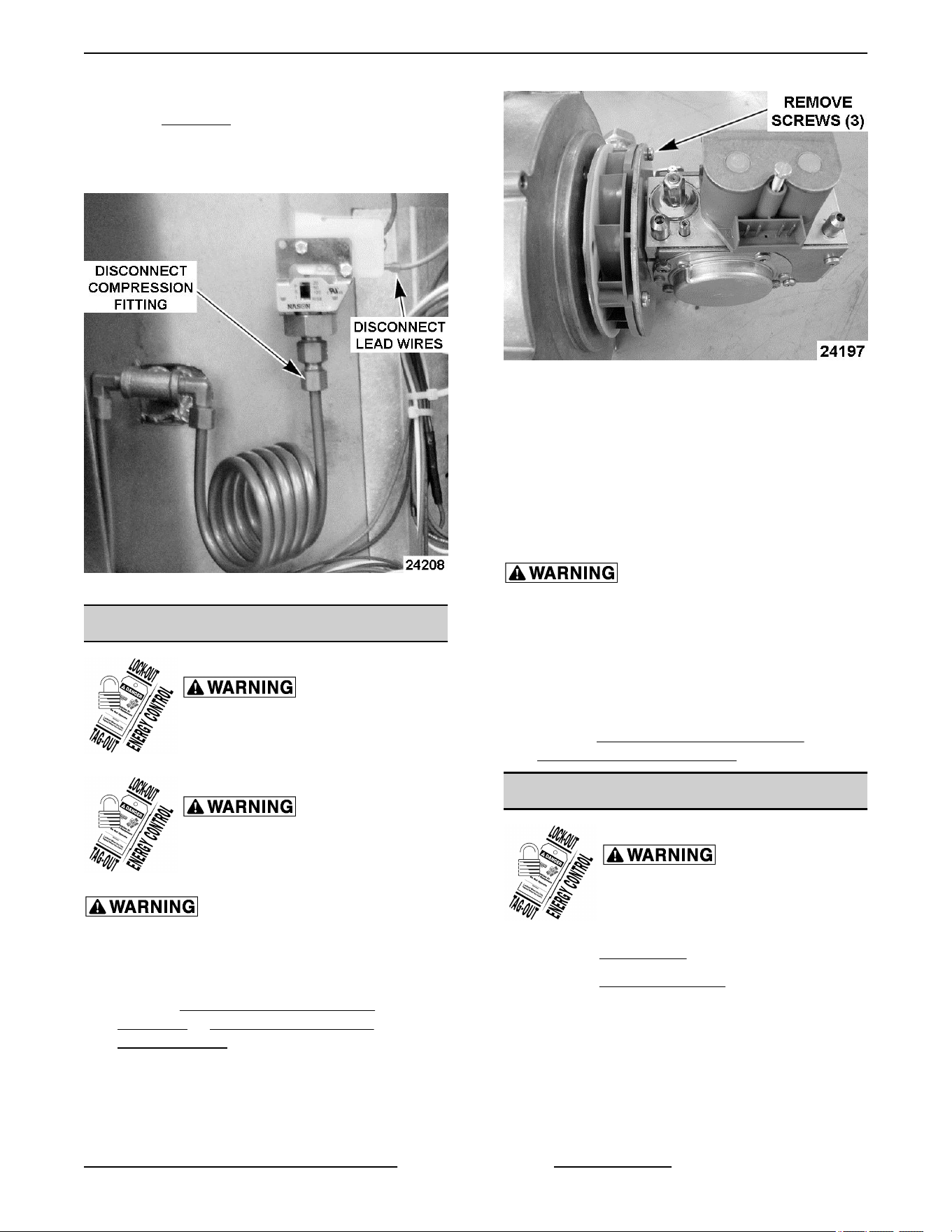
PRESSURE SWITCH (1PAS)
Disconnect the electrical power to
the machine and follow lockout /
tagout procedures.
1. Open pressure relief valve until reservoir jacket
is completely vented.
2. Remove CORNER PANEL (TILTING) or SIDE
PANEL (STATIONARY).
3. Remove pressure switch from tubing.
4. Reverse procedure to install.
K Series Gas Kettles 2/3 Jacketed Stationary and Tilting - REMOVAL AND REPLACEMENT OF PARTS
F45461 Rev. E (0124) Page 10 of 55
5. Remove air from reservoir jacket as outlined
under VENTING procedure.
6. Check for proper operation.
NOTE: Pressure switch is set to open at 38-42 PSI.
Fig. 11
GAS VALVE
Disconnect the electrical power to
the machine and follow lockout /
tagout procedures.
Shut off the gas before servicing the
unit and follow lockout / tagout
procedures.
All gas joints disturbed during servicing must be
checked for leaks. Check with a soap and water
solution (bubbles). Do not use an open flame.
1. Remove CORNER & REAR PANELS
(TILTING) or SIDE & REAR PANELS
(STATIONARY).
2. Remove electrical connector from gas valve.
3. Disconnect gas line from gas valve.
4. Remove gas valve from blower.
Fig. 12
5. Remove piping from gas valve inlet and install on
replacement valve. Ensure the factory tags that
are wired to the piping remain installed.
NOTE: Replacement gas valve contains valve plate,
orifice and o-ring already assembled. The gas valve/
blower design allows natural and propane gas kettles
to use the same orifice size. Labels for gas type are
also included.
Clean pipe threads and apply thread sealant that
is suitable for use with propane gas.
6. Reverse procedure to install.
7. Affix the appropriate gas label (natural or
propane) on top of gas valve.
8. Perform GAS VALVE/BLOWER INLET
PRESSURE CHECK (108W).
BLOWER
Disconnect the electrical power to
the machine and follow lockout /
tagout procedures.
1. Remove GAS VALVE from blower.
2. Remove BOTTOM COVER.
3. Separate burner manifold compression fitting on
gas supply tube (feeding burner).
K Series Gas Kettles 2/3 Jacketed Stationary and Tilting - REMOVAL AND REPLACEMENT OF PARTS
Page 11 of 55 F45461 Rev. E (0124)
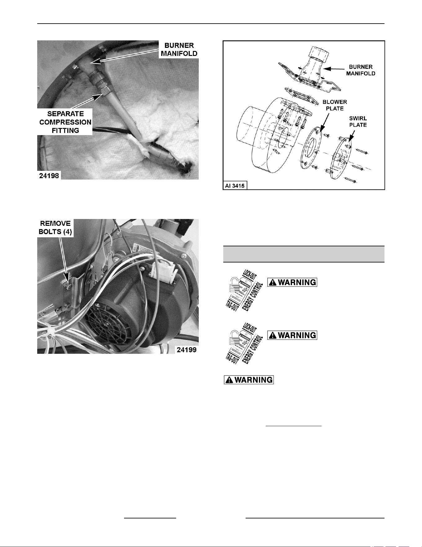
Fig. 13
4. Remove electrical connectors (2) from blower.
5. Remove blower from kettle at burner manifold.
Fig. 14
A. Remove blower from burner manifold (4
screws).
B. Remove swirl plate (3 screws) and blower
plate (2 screws) from blower intake.
Fig. 15
6. Reverse procedure to install replacement blower
and check for proper operation.
NOTE: Install replacement blower gasket as
necessary.
BURNER
Disconnect the electrical power to
the machine and follow lockout /
tagout procedures.
Shut off the gas before servicing the
unit and follow lockout / tagout
procedures.
All gas joints disturbed during servicing must be
checked for leaks. Check with a soap and water
solution (bubbles). Do not use an open flame.
1. Remove BOTTOM COVER.
2. Remove clips securing insulation to bottom of
kettle.
A. Gently remove insulation and save for
reuse.
3. Disconnect spark ignitor lead wires at the ignition
module.
4. Separate compression nuts on gas supply tube.
K Series Gas Kettles 2/3 Jacketed Stationary and Tilting - REMOVAL AND REPLACEMENT OF PARTS
F45461 Rev. E (0124) Page 12 of 55
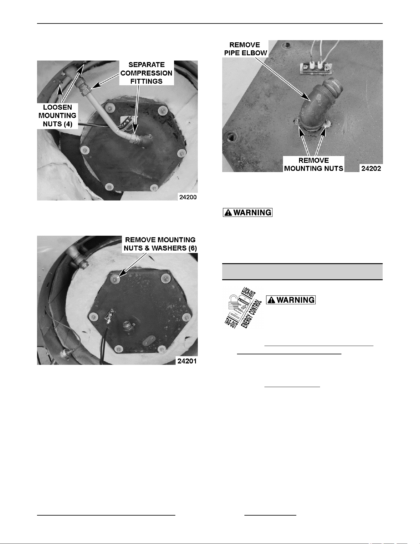
5. Loosen gas manifold mounting nuts and remove
gas supply tube from the fittings.
Fig. 16
6. Remove combustion chamber cover from bottom
of kettle.
Fig. 17
7. Note alignment of pipe elbow connected to
burner. Remove elbow from burner.
8. Remove burner from combustion chamber cover.
Fig. 18
9. Reverse procedure to install replacement burner
and check for proper operation.
Apply pipe thread sealant to burner threads that is
suitable for use with propane gas.
NOTE: Torque mounting nuts for combustion
chamber cover to 30 ft-lb.
SPARK IGNITOR
Disconnect the electrical power to
the machine and follow lockout /
tagout procedures.
1. Remove CONTROL BOX COVER (TILTING) or
CORNER PANEL (STATIONARY).
2. Disconnect spark ignitor lead wires at ignition
module.
3. Remove BOTTOM COVER.
4. Remove clips holding insulation against
combustion chamber cover.
5. Remove spark ignitor from combustion chamber
cover.
K Series Gas Kettles 2/3 Jacketed Stationary and Tilting - REMOVAL AND REPLACEMENT OF PARTS
Page 13 of 55 F45461 Rev. E (0124)
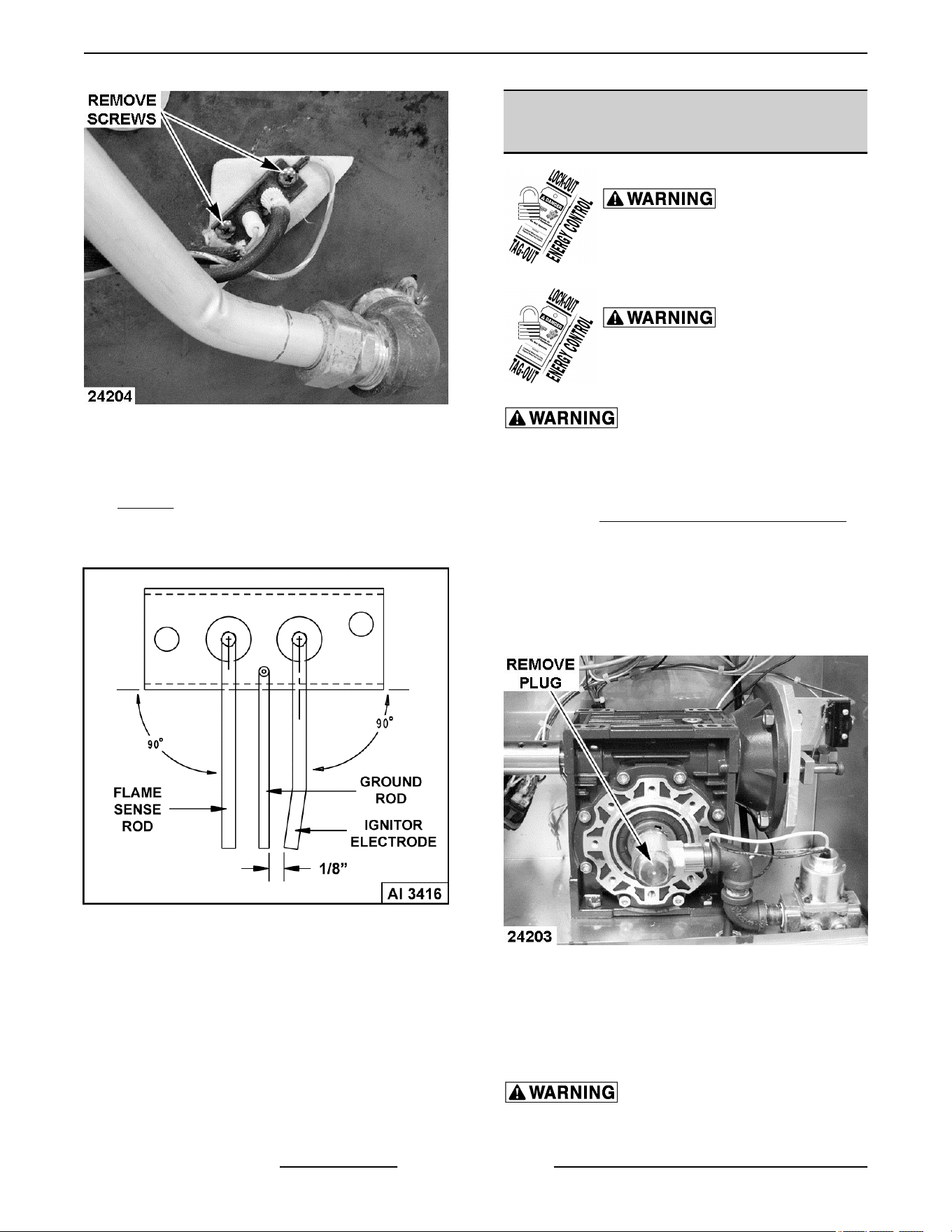
Fig. 19
6. Ensure spark gap between ignitor electrode and
ground rod is approximately 1/8". If necessary,
adjust as outline under SPARK IGNITION TEST
Step 8C.
7. Reverse procedure to install and check for proper
operation.
Fig. 20
GAS SHUT-OFF VALVE (1SOL) -
TILTING MODELS ONLY
Disconnect the electrical power to
the machine and follow lockout /
tagout procedures.
Shut off the gas before servicing the
unit and follow lockout / tagout
procedures.
All gas joints disturbed during servicing must be
checked for leaks. Check with a soap and water
solution (bubbles). Do not use an open flame.
1. Remove
CONTROL BOX COVER (TILTING).
2. Disconnect lead wires for gas shut-off valve
(1SOL) at terminal strip in control box.
3. Remove piping from inlet side of valve.
4. Remove threaded plug (NPT) from the ½” swivel
fitting secured to end of pivot shaft.
K20GLT Manual Tilt Shown
5. Remove gas shut-off valve from control box.
6. Remove piping from outlet side of valve.
7. Reverse procedure to install replacement gas
shut-off valve and check for proper operation.
Clean pipe threads and apply thread sealant that
is suitable for use with propane gases.
K Series Gas Kettles 2/3 Jacketed Stationary and Tilting - REMOVAL AND REPLACEMENT OF PARTS
F45461 Rev. E (0124) Page 14 of 55
GEAR REDUCER - MANUAL
TILTING MODELS
Disconnect the electrical power to
the machine and follow lockout /
tagout procedures.
Shut off the gas before servicing the
unit and follow lockout / tagout
procedures.
All gas joints disturbed during servicing must be
checked for leaks. Check with a soap and water
solution (bubbles). Do not use an open flame.
1. Place kettle in the fully upright position and
remove crank handle.
2. Support kettle from the bottom in some manner
(2x4 etc). Raise it slightly to take the kettle arm
weight off gear reducer.
3. Remove
GAS SHUT-OFF VALVE (1SOL) -
TILTING MODELS ONLY.
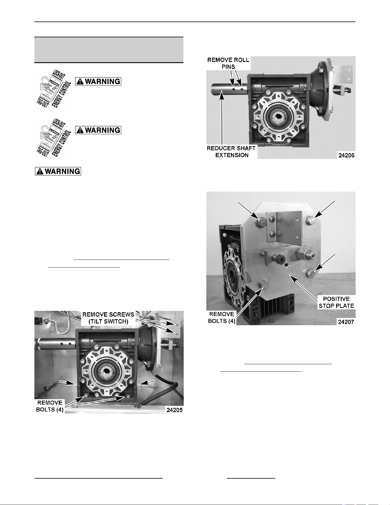
4. Remove tilt switch (2S) from bracket leaving the
lead wires connected.
5. Remove bolts securing gear reducer and control
box to kettle frame.
Fig. 22
6. Pull gear reducer away from kettle by working it
off the kettle arm until free. Note that the kettle
arm is keyed.
NOTE: Control box can be moved as necessary for
ease of gear reducer removal.
7. Remove reducer shaft extension from gear
reducer shaft.
Fig. 23
8. Remove positive stop plate from gear reducer.
Note that the positive stop shaft is keyed.
Fig. 24
9. Reverse procedure to install replacement gear
reducer.
10. Perform KETTLE TILT ADJUSTMENT -
MANUAL TILTING MODELS to check for proper
operation.
K Series Gas Kettles 2/3 Jacketed Stationary and Tilting - REMOVAL AND REPLACEMENT OF PARTS
Page 15 of 55 F45461 Rev. E (0124)
ELECTRICAL PANEL
COMPONENTS - POWER TILTING
OPTION ONLY
Disconnect the electrical power to
the machine and follow lockout /
tagout procedures.
1. Remove CONTROL BOX COVER (TILTING).
2. Disconnect lead wires from component being
replaced.
3. Remove screws securing the component to
panel.
4. Reverse procedure to install and check for proper
operation.
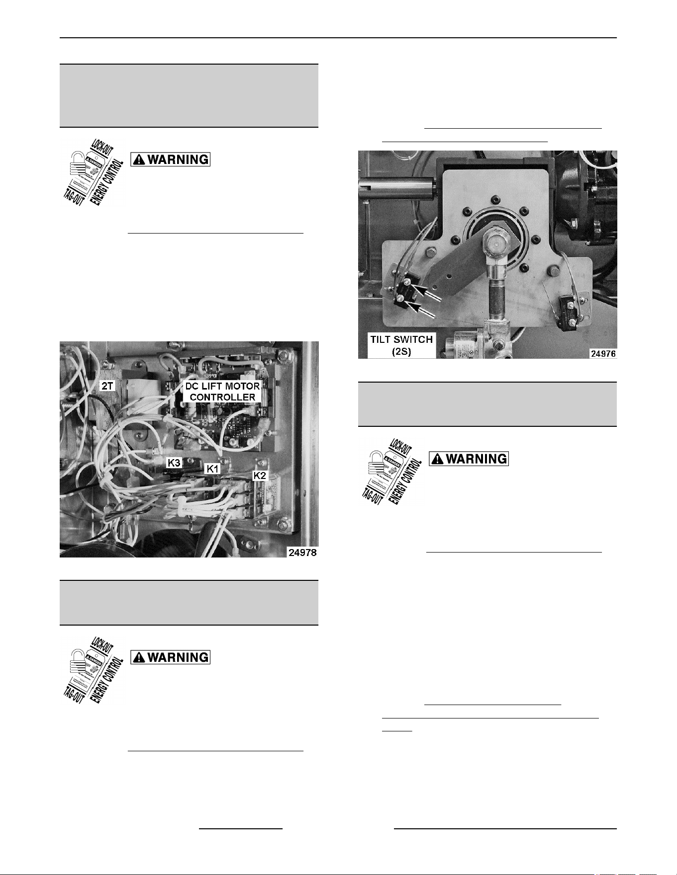
Fig. 25
TILT SWITCH (2S) - POWER
TILTING OPTION ONLY
Disconnect the electrical power to
the machine and follow lockout /
tagout procedures.
1. Place kettle in the fully upright position.
2. Remove CONTROL BOX COVER (TILTING).
3. Note lead wire locations and disconnect from tilt
switch (2S).
4. Remove adjustment screws (2) securring switch
bracket to mounting plate.
5. Remove mounting nuts and screws (2) securring
tilt switch (2S) to bracket.
6. Reverse procedure to install tilt switch (2S).
7. Perform TILT SWITCH (2S) ADJUSTMENT -
POWER TILTING OPTION ONLY.
Fig. 26
DOWN LIMIT SWITCH (3S) - POWER
TILTING OPTION ONLY
Disconnect the electrical power to
the machine and follow lockout /
tagout procedures.
1. Place kettle in the fully upright position.
2. Remove CONTROL BOX COVER (TILTING).
3. Note lead wire locations and disconnect from
down limit switch (3S).
4. Remove adjustment screws (2) securring switch
bracket to mounting plate.
5. Remove mounting nuts and screws (2) securring
down limit switch (3S) to bracket.
6. Reverse procedure to install down limit switch
(3S).
7. Perform DOWN LIMIT SWITCH (3S)
ADJUSTMENT - POWER TILTING OPTION
ONLY.
K Series Gas Kettles 2/3 Jacketed Stationary and Tilting - REMOVAL AND REPLACEMENT OF PARTS
F45461 Rev. E (0124) Page 16 of 55
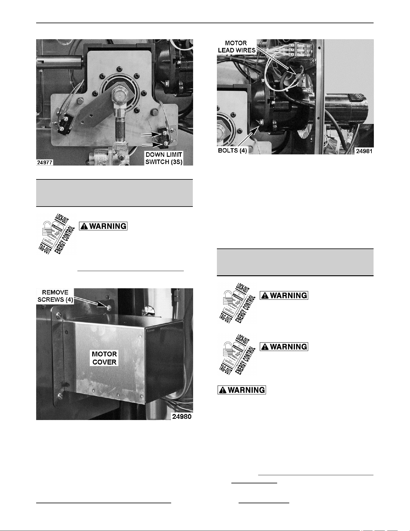
Fig. 27
DC TILT MOTOR - POWER TILTING
OPTION ONLY
Disconnect the electrical power to
the machine and follow lockout /
tagout procedures.
1. Remove CONTROL BOX COVER (TILTING).
2. Remove motor cover from rear of control box.
Fig. 28
3. Disconnect DC tilt motor lead wires (2) at quick
disconnect terminals. The wires are labeled MTR
positive (+) and MTR negative (-).
4. Disconnect motor ground wire.
5. Remove motor mounting bolts and lock washers
from gear reducer flange.
Fig. 29
6. Remove motor from gear reducer.
7. To install:
A. With drive key on shaft, install motor to gear
reducer.
B. Re-connect motor lead wires.
C. Replace motor cover and control box cover.
8. Check for proper operation.
GEAR REDUCER - POWER TILTING
OPTION ONLY
Disconnect the electrical power to
the machine and follow lockout /
tagout procedures.
Shut off the gas before servicing the
unit and follow lockout / tagout
procedures.
All gas joints disturbed during servicing must be
checked for leaks. Check with a soap and water
solution (bubbles). Do not use an open flame.
1. Place kettle in the fully upright position.
2. Support kettle from the bottom in some manner
(2x4 etc.). Raise it slightly to take the kettle pivot
shaft weight off gear reducer.
3. Remove TILT SWITCH (2S) - POWER TILTING
OPTION ONLY leaving the lead wires
connected.
K Series Gas Kettles 2/3 Jacketed Stationary and Tilting - REMOVAL AND REPLACEMENT OF PARTS
Page 17 of 55 F45461 Rev. E (0124)
4. Remove DOWN LIMIT SWITCH (3S) - POWER
TILTING OPTION ONLY leaving the lead wires
connected.
5. Remove GAS SHUT-OFF VALVE (1SOL) -
TILTING MODELS ONLY.
6. Remove DC TILT MOTOR - POWER TILTING
OPTION ONLY.
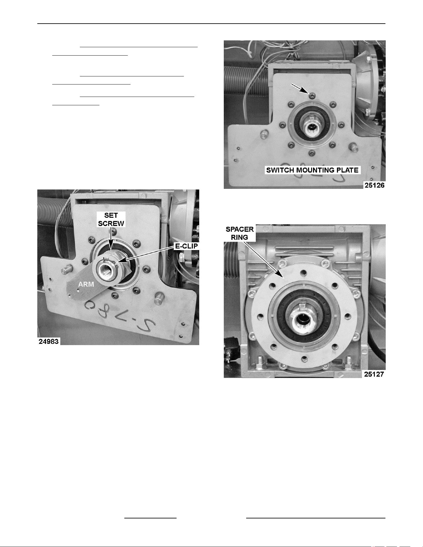
7. Loosen set screw securing arm to kettle pivot
shaft (keyed).
8. Remove e-clip securing arm to kettle pivot shaft.
Note orientation and remove arm from kettle
pivot shaft.
NOTE: If installed, note the number of washers in
front of and behind the arm on the kettle pivot shaft for
re-assembly.
Fig. 30
9. Remove switch mounting plate screws (8) from
gear reducer and lift plate away from gear
reducer.
Fig. 31
10. Lift spacer ring off gear reducer. Retain for use
on replacement gear reducer.
Fig. 32
11. Remove bolts (4) securing gear reducer and
control box to kettle frame.
NOTE: A one piece nut plate assembly may be
installed at the rear of gear reducer in place of
individual mounting nuts to ease assembly.
K Series Gas Kettles 2/3 Jacketed Stationary and Tilting - REMOVAL AND REPLACEMENT OF PARTS
F45461 Rev. E (0124) Page 18 of 55
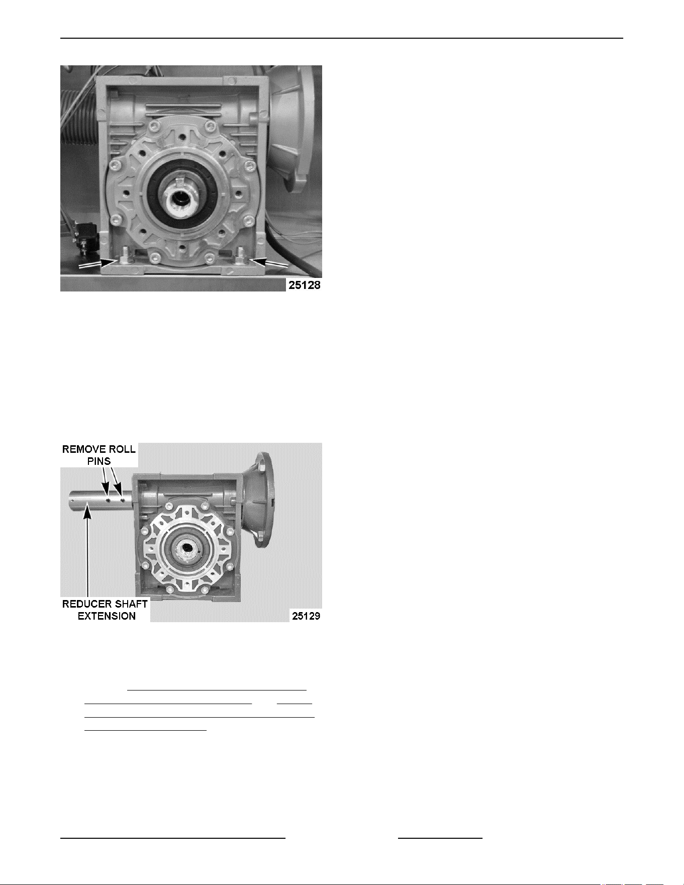
Fig. 33
12. Pull gear reducer away from kettle by working it
off the kettle pivot shaft until free. Retain key for
use on replacement gear reducer.
NOTE: Control box can be moved as necessary for
ease of gear reducer removal.
13. Remove reducer shaft extension from gear
reducer shaft (2 roll pins). Retain for use on
replacement gear reducer.
Fig. 34
14. Reverse procedure to install replacement gear
reducer.
15. Perform TILT SWITCH (2S) ADJUSTMENT -
POWER TILTING OPTION ONLY and DOWN
LIMIT SWITCH (3S) ADJUSTMENT - POWER
TILTING OPTION ONLY.
K Series Gas Kettles 2/3 Jacketed Stationary and Tilting - REMOVAL AND REPLACEMENT OF PARTS
Page 19 of 55 F45461 Rev. E (0124)
SERVICE PROCEDURES AND ADJUSTMENTS
Certain procedures in this section require electrical test or measurements while power is applied to the
machine. Exercise extreme caution at all times. If test points are not easily accessible, disconnect power
and follow lockout / tagout procedures, attach test equipment and reapply power to the test.
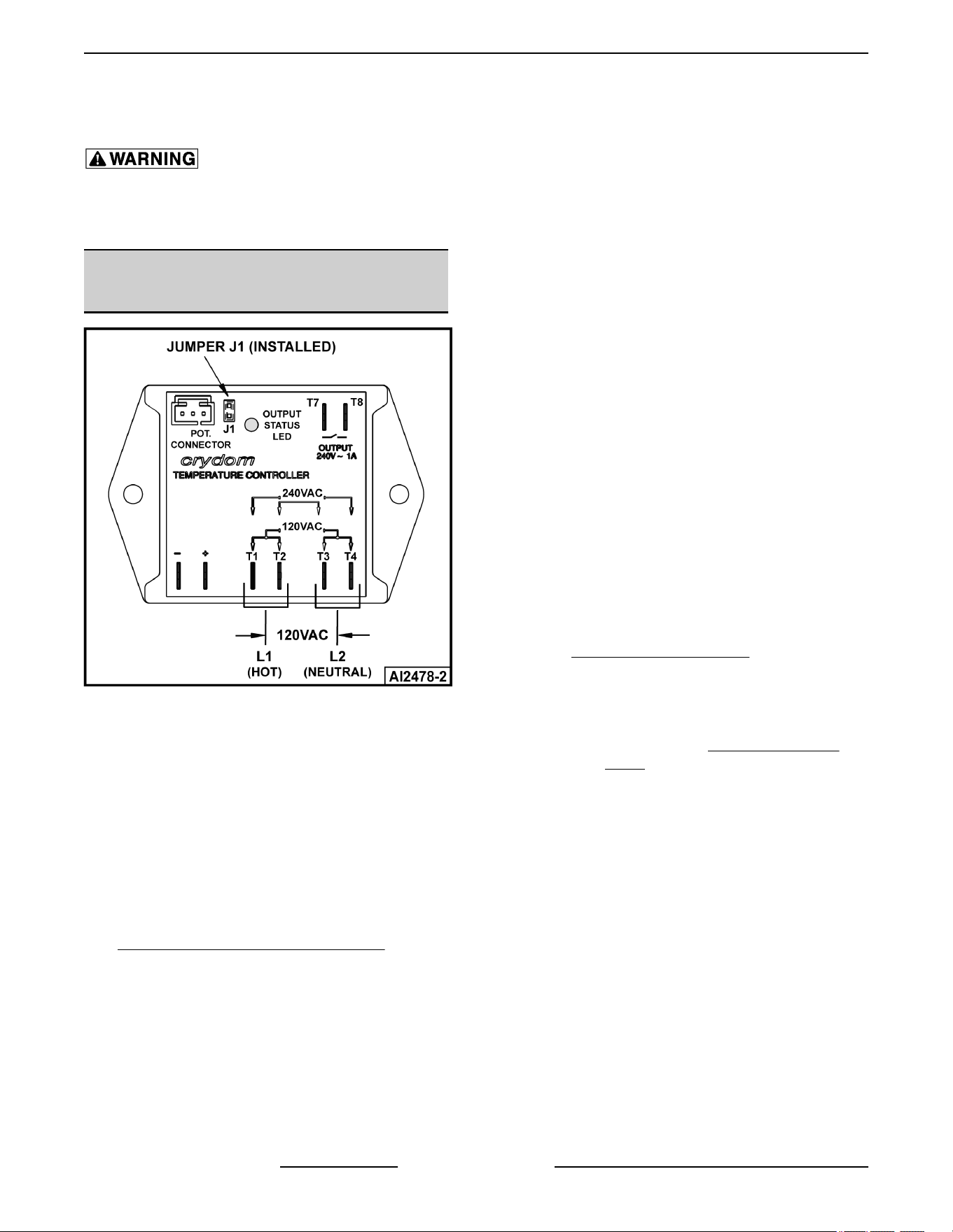
TEMPERATURE CONTROLLER
TEST
Fig. 35
1. Place kettle in full upright position (tilting models
only).
2. Set temperature dial to lowest setting. Kettle
must be below 110°F before verifying the
potentiometer output to the controller is good
over the full range of temperature dial travel.
3. Access the temperature controller as outlined in
ELECTRICAL PANEL COMPONENTS.
4. Check all lead wires for secure connections to the
controller terminals. Wiring harness lead wires
must be connected to T1-T2 and T3-T4 for proper
input to controller.
5. Re-connect power to the machine.
6. Turn power switch on.
7. Verify temperature controller is receiving
120VAC at terminals T1-T3 and T2-T4 and
machine is properly grounded.
8. Slowly turn temperature dial to the highest setting
and monitor heat light over the full range of travel.
A. Verify heat light (amber) comes on, blower
motor comes on and transformer is powered
(120VAC).
B. If the components listed above are
functioning properly, then output from T8 on
controller should be present. As long as
transformer output voltage is correct
(24VAC), heat circuit is powered and the
ignition sequence to light the burner will
start.
C. If heat light does not remain on or flashes
momentarily as temperature setting is
slowly increased, verify condition of
potentiometer as outlined under
POTENTIOMETER TEST.
D. If heat light or blower motor is not coming
on; or transformer is not powered.
1) Verify condition of thermocouple as
outlined under THERMOCOUPLE
TEST.
NOTE: Temperature controller will de-energize
internal relay and turn off the output status LED if the
circuitry detects an open thermocouple. LED will begin
to flash 3 times, pause, then repeat the flash sequence
to indicate the open thermocouple condition.
2) Check lead wire connections at the
component that is not functioning (heat
light, blower motor or transformer).
3) Verify power at the component that is
not functioning. If power is present,
determine if the component is
malfunctioning. If power is not present
at any of the components, continue
with procedure.
9. Disconnect lead wire from terminal T7 on the
controller.
K Series Gas Kettles 2/3 Jacketed Stationary and Tilting - SERVICE PROCEDURES AND ADJUSTMENTS
F45461 Rev. E (0124) Page 20 of 55
A. Verify 120VAC between lead wire from T7
and ground. If correct, re-connect lead wire
to terminal T7 and continue with procedure.
B. If incorrect, check pressure switch (1PS)
and water level controller (WLC LLCO).
10. Disconnect lead wire from terminal T8 on the
controller.
A. Verify 120VAC between T8 and ground. If
correct, output from controller is functioning
properly.
B. If incorrect, install a replacement
temperature controller and check for proper
operation.
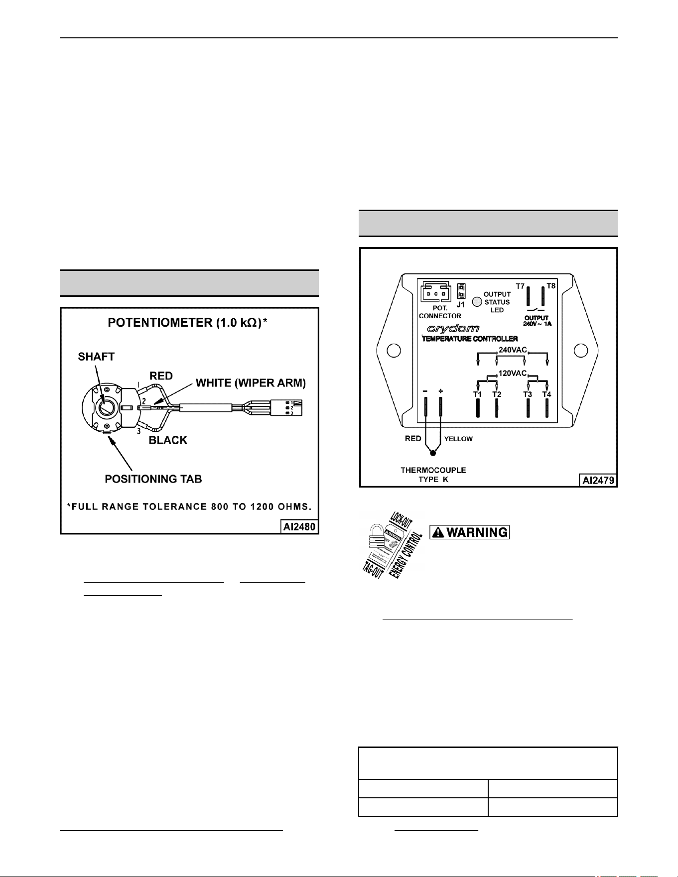
POTENTIOMETER TEST
Fig. 36
1. Access control panel potentiometer by removing
CORNER PANEL (TILTING) or SIDE PANEL
(STATIONARY).
2. Turn potentiometer shaft fully counterclockwise
to the lowest setting.
3. Set VOM to measure resistance.
4. Connect meter leads to the white and black lead
wires on potentiometer terminals.
A. Resistance should measure approximately
zero ohms.
5. Slowly turn potentiometer shaft clockwise over
the full range of travel and monitor resistance
change on the meter.
A. Resistance should measure 800 to 1200
ohms with shaft turned fully clockwise.
B. If the resistance value increased smoothly
without sudden drops or spikes and the full
travel resistance value is within tolerance
then potentiometer is functioning properly.
C. If the resistance value did not increase
smoothly but had drops or spikes over the
full travel range then potentiometer is not
functioning properly. Install a replacement
potentiometer and check for proper
operation.
THERMOCOUPLE TEST
Fig. 37
Disconnect the electrical power to
the machine and follow lockout /
tagout procedures.
1. Access temperature controller as outlined in
ELECTRICAL PANEL COMPONENTS.
2. Remove thermocouple lead wires from
temperature controller.
3. Check the thermocouple for a measurable
resistance (approximately 5 to 10 ohms at room
temperature). If meter reads an overload (OL)
condition (open), or zero ohms (short) replace
the thermocouple and check temperature
controller for proper operation.
TYPE K THERMOCOUPLE PROBE AND
MILLIVOLT CHART
TEMPERATURE MILLIVOLT
100° F 1.521
K Series Gas Kettles 2/3 Jacketed Stationary and Tilting - SERVICE PROCEDURES AND ADJUSTMENTS
Page 21 of 55 F45461 Rev. E (0124)
TYPE K THERMOCOUPLE PROBE AND
MILLIVOLT CHART
TEMPERATURE MILLIVOLT
150° F 2.667
200° F 3.820
250° F 4.925
300° F 6.094
350° F 7.207
400° F 8.316
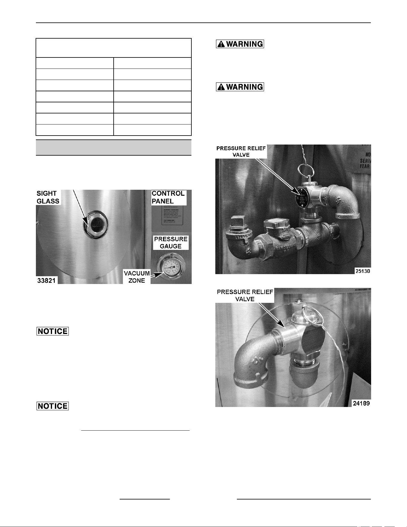
VENTING
NOTE: This procedure outlines venting the reservoir
jacket to remove air for proper heat transfer to kettle
contents.
Fig. 38
1. With kettle at room temperature, verify pressure
gauge is in vacuum zone and reading 25 to 30 in.
Hg.
If vacuum is below minimum listed, air must be
removed from reservoir jacket. Continue with
procedure to vent as necessary.
2. Place kettle in full upright position (tilting models
only).
3. Verify water level.
If Low water light is lit on control panel, add distilled
water. Refer to FILLING THE RESERVOIR JACKET.
4. Turn power switch on.
5. Set temperature dial to highest setting. Allow
kettle to heat until the jacket pressure reaches 10
PSI.
Pressure Relief Valve Exhaust. DO NOT connect
to building water, gas, or steam supply. DO NOT
block or restrict.
Hot steam. The kettle and its parts are hot. Use
care when operating, cleaning or servicing the
kettle.
6. Open pressure relief valve for approximately 10
seconds. Allow valve to snap shut to seal.
Current Construction
Previous Construction
7. Turn power switch off and allow kettle to cool
(room temperature).
Verify pressure gauge reading is within correct
vacuum range.
A. If reading is below minimum listed or will not
maintain proper vacuum, check all threaded
fittings extending from the kettle couplings
for leaks and tightness.
K Series Gas Kettles 2/3 Jacketed Stationary and Tilting - SERVICE PROCEDURES AND ADJUSTMENTS
F45461 Rev. E (0124) Page 22 of 55
1) Check pressure relief valve for leaks
from poor valve seating or built up
debris. Manually operate valve several
times to reseat. Allow valve to snap
shut to seal. Repeat venting
procedure.
2) If pressure relief valve is
malfunctioning, install a replacement
and check for proper operation.
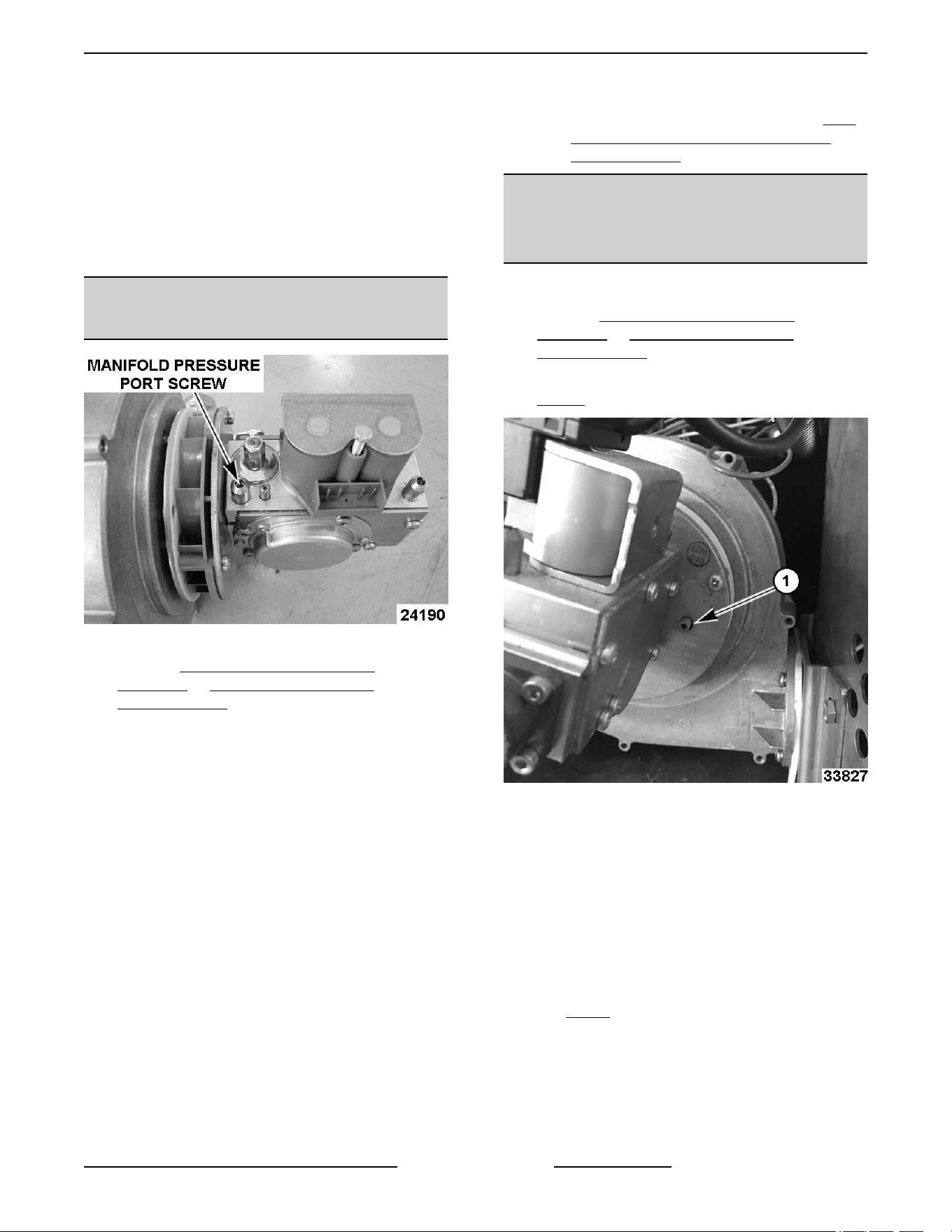
BLOWER INLET PRESSURE
CHECK ENDING AT SN 46-3028411
Fig. 41
1. Remove CORNER & REAR PANELS
(TILTING) or SIDE & REAR PANELS
(STATIONARY) to access blower & gas valve.
2. Remove electrical connector from gas valve.
3. Open manifold pressure port. Turn screw 1 to 2
turns CCW.
4. Attach U inclined manometer hose to manifold
pressure port.
5. Turn Kettle on.
6. Measure blower vacuum pressure.
A. Blower low speed (during trial for ignition, 7
sec) - Vacuum pressure reading should be
0.27" W.C. to 0.30" W.C.
B. Blower high speed (15 sec. time delay) -
Vacuum pressure should be 1.91" W.C. to
1.98" W.C.
C. If vacuum pressure reading is outside of the
values stated above, check blower air inlet
for debris buildup/obstructions. If found, turn
power switch off. Remove debris and retest.
D. If vacuum pressure results are the same
after retest, replace blower. Perform GAS
VALVE/BLOWER INLET PRESSURE
CHECK (108W).
BLOWER INLET PRESSURE
CHECK 2ND GENERATION
STARTING AT SN 46-3028412
1. Turn gas supply off.
2. Remove CORNER & REAR PANELS
(TILTING) or SIDE & REAR PANELS
(STATIONARY) to access blower and gas valve.
3. Attach U inclined manometer hose to test port (1,
Fig. 42).
Fig. 42
4. Turn gas supply on.
5. Turn Kettle on.
6. Set-up burner with combustion analyzer.
A. Verify or set speed control board settings.
• Low Fire is set to 8. Air pressure -0.06.
• High Fire is set to C-. Air pressure
-0.19.
NOTE: Step 2 for setting of a new valve or if starting
with a raw adjustment.
B. Turn adjustment screw on the gas valve
counterclockwise 10 turns for propane or 15
turns for natural gas.
C. Turn temperature control to BOIL and turn
on power switch to initiate ignition series.
K Series Gas Kettles 2/3 Jacketed Stationary and Tilting - SERVICE PROCEDURES AND ADJUSTMENTS
Page 23 of 55 F45461 Rev. E (0124)
D. After 10 minute warmup, begin sampling
flue gas with a calibrated analyzer. (natural
gas / propane).
• Verify CO2 reading is 10% - 12%
(natural gas / propane).
• Verify combustion analyzer reports CO
air free of less than 50 ppm. If not, turn
adjustment screw counterclockwise to
lower CO.
7. Measure blower vacuum pressure.
A. Blower low speed (during trial for ignition, 7
sec) - Vacuum pressure reading should be
0.06" W.C.
B. Blower high speed (15 sec. time delay) -
Vacuum pressure should be .19" W.C.
C. If vacuum pressure reading is outside of the
values stated above, check blower air inlet
for debris buildup/obstructions. If found, turn
power switch off. Remove debris and retest.
D. If vacuum pressure results are the same
after retest, replace blower. Perform GAS
VALVE/BLOWER INLET PRESSURE
CHECK FOR 2ND GENERATION
STARTING AT SN 46-3028412.
8. Turn gas supply off.
9. Reverse procedure to install access panels.
10. Turn gas supply on.
GAS VALVE/BLOWER INLET
PRESSURE CHECK (108W)
Shut off the gas before servicing the
unit and follow lockout / tagout
procedures.
NOTE: Wattage is listed on blower label.
Fig. 43
1. Remove CORNER & REAR PANELS
(TILTING) or SIDE & REAR PANELS
(STATIONARY) to access blower & gas valve.
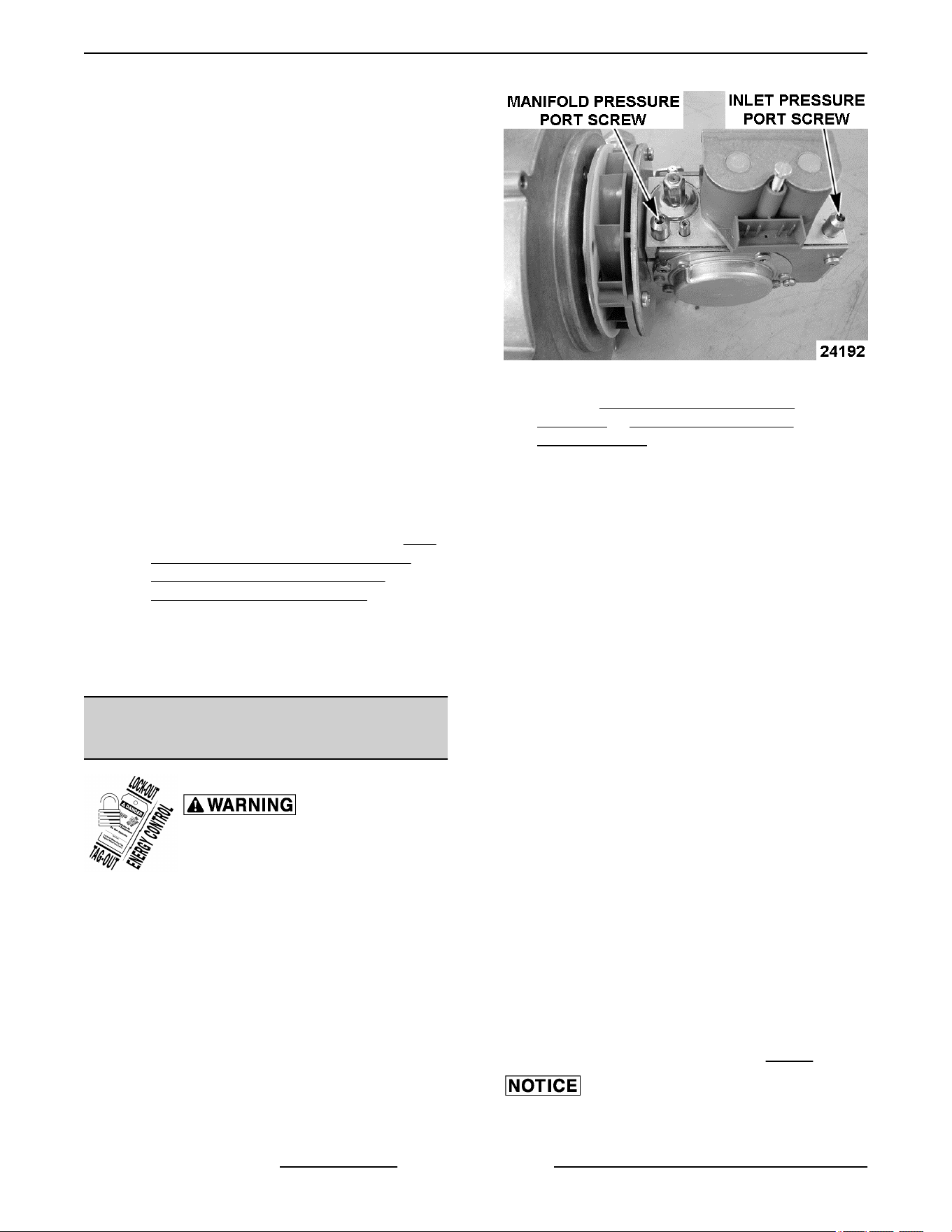
2. Open inlet pressure port. Turn screw 1 to 2 turns
CCW.
3. Attach slack tube manometer hose to inlet
pressure port.
4. Attach U inclined manometer hose to manifold
pressure port.
5. Turn kettle on.
6. Measure blower vacuum pressure.
A. Blower low speed (during trial for ignition, 7
sec.) - Vacuum pressure reading should be
0.27" W.C. to 0.30" W.C.
B. Blower high speed (15 sec. time delay) -
Vacuum pressure should be 1.91" W.C. to
1.98" W.C.
C. If vacuum pressure reading is outside of the
values stated above, check blower air inlet
for debris buildup / obstructions. If found,
turn power switch off. Remove debris and
retest.
7. Reconnect power and turn gas supply on.
NOTE: If static line pressure exceeds 14" W.C. (½
psig) the customer must supply and install a line
pressure regulator to reduce the pressure below the
maximum allowable for the valve.
8. Turn Kettle on.
9. Verify inlet pressure is 5-7" W.C. (natural) and
11-13" W.C. (propane). Refer to: Fig. 45.
If inlet pressure is excessive, contact the local gas
supply company to adjust incoming line pressure.
K Series Gas Kettles 2/3 Jacketed Stationary and Tilting - SERVICE PROCEDURES AND ADJUSTMENTS
F45461 Rev. E (0124) Page 24 of 55
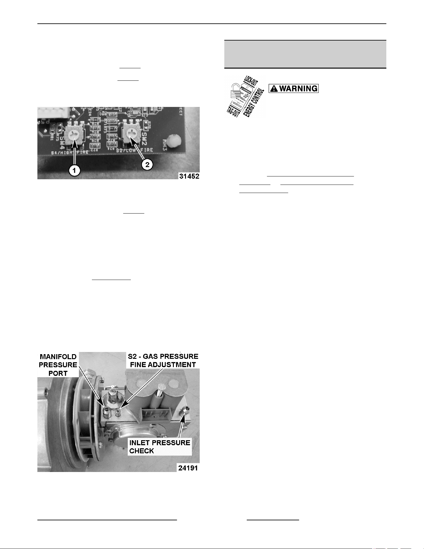
10. Verify combustion blower motor speed, control
board settings.
• High Fire = F (1, Fig. 44)
• Low Fire = 9 (2, Fig. 44)
NOTE: The head of the arrow cut out in the center will
designate the rotary switch setting.
Fig. 44
To Adjust:
1. Turn S2 gas pressure (Fig. 45) fine adjustment
screw 1/4 turn (CW to increase; CCW to
decrease).
2. Turn power switch off then back on and check
pressure readings. Repeat adjustment as
required.
A. If unable to achieve correct pressure, then
replace
GAS VALVE. Preset S2 - gas
pressure fine adjustment screw on the
replacement valve. Turn screw fully
clockwise until it stops.
Natural - Turn screw 15 turns
counterclockwise.
Propane - Turn screw 9 turns
counterclockwise.
Fig. 45
GAS VALVE/BLOWER INLET
PRESSURE CHECK (130W)
Shut off the gas before servicing the
unit and follow lockout / tagout
procedures.
NOTE: This check is for K series gas kettle models,
K20GL, K20GLT, K40GL, K40GLT, K60GL, K60GLT
with serial number 463023802 to present and built on
5/10/17 or after.
1.
Remove CORNER & REAR PANELS
(TILTING) or SIDE & REAR PANELS
(STATIONARY) to access blower & gas valve.
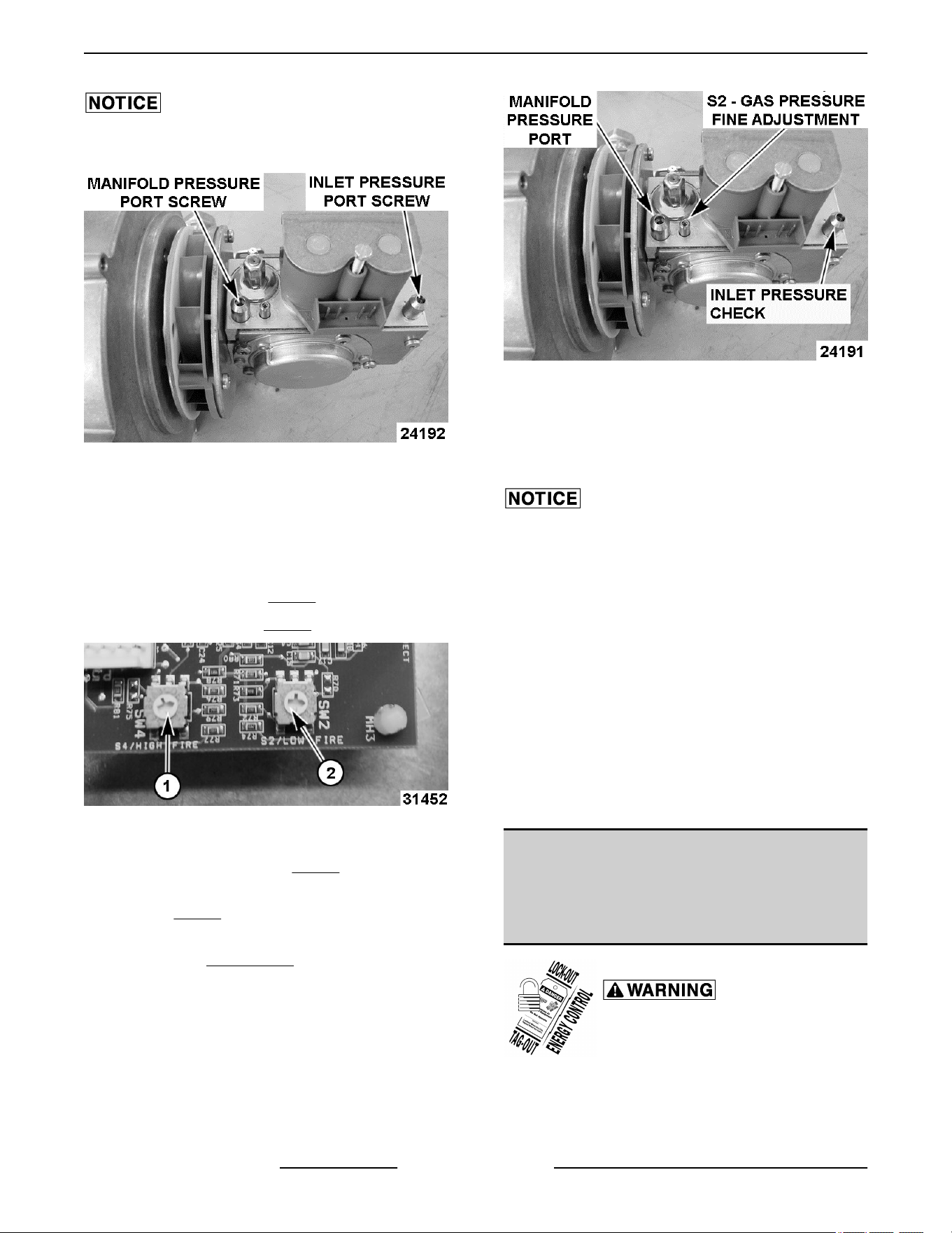
2. Open inlet pressure port. Turn screw 1 to 2 turns
CCW.
3. Attach slack tube manometer hose to inlet
pressure port.
4. Attach U inclined manometer hose to manifold
pressure port.
5. Turn kettle on.
6. Measure blower vacuum pressure.
A. Blower low speed (during trial for ignition, 7
sec.) - Vacuum pressure reading should be
0.27" W.C. to 0.30" W.C.
B. Blower high speed (15 sec. time delay) -
Vacuum pressure should be 1.91" W. C. to
1.98" W.C.
7. Verify incoming gas line to kettle is a ¾” ID
commercial gas line.
8. Verify incoming gas supply line pressure is
7“ Water Column (natural gas) and 11” Water
Column (propane).
K Series Gas Kettles 2/3 Jacketed Stationary and Tilting - SERVICE PROCEDURES AND ADJUSTMENTS
Page 25 of 55 F45461 Rev. E (0124)
If inlet pressure is excessive, contact the local gas
supply company to adjust incoming line pressure.
Fig. 46
9. Verify combustion blower motor speed, control
board settings.
NOTE: The head of the arrow cut out in the center will
designate the rotary switch setting. "F" and "8" are
designations on the potentiometer.
• High Fire = F (1,
Fig. 47)
• Low Fire = 8 (2, Fig. 47)
Fig. 47
10. Turn fine adjustment screw on gas valve
clockwise all the way in. (Fig. 48)
11. Adjust gas valve fine adjustment screw for type
of gas. (Fig. 48)
A. If unable to achieve correct pressure, then
replace GAS VALVE. Preset S2 - gas
pressure fine adjustment screw on the
replacement valve. Turn screw fully
clockwise until it stops.
• Propane: Turn fine adjustment screw on
gas valve counterclockwise 9 turns.
• Natural Gas: Turn fine adjustment screw on
gas valve counterclockwise 15 turns.
Fig. 48
12. Turn temperature control to “BOIL” and turn on
power switch to initiate ignition series.
13. After a warmup of 10 minutes begin sampling flue
gas with a calibrated analyzer.
Flue gasses must be checked with a combustion
analyzer. Combustion limits are listed below. If the
burner system fails to meet these requirements,
please call Steam Technical Support immediately.
Insert sampling probe into flue discharge, located
towards the rear of kettle. Ensure the probe is inserted
in such a way that the sample gas is not diluted. Place
the probe 1-2 inches below the discharge.
14. Make further adjustments to fine adjustment
screw if needed to obtain CO2 reading of 10.5%
to 12.0% (Natural Gas) or 12.0% to 13.5%
(propane).
15. Verify combustion analyzer reports CO air free of
less than 400ppm (.04%). If not, turn fine
adjustment screw CW to lower CO.
GAS VALVE/BLOWER INLET
PRESSURE CHECK FOR 2ND
GENERATION STARTING AT SN
46-3028412
Shut off the gas before servicing the
unit and follow lockout / tagout
procedures.
NOTE: Wattage is listed on blower label.
K Series Gas Kettles 2/3 Jacketed Stationary and Tilting - SERVICE PROCEDURES AND ADJUSTMENTS
F45461 Rev. E (0124) Page 26 of 55
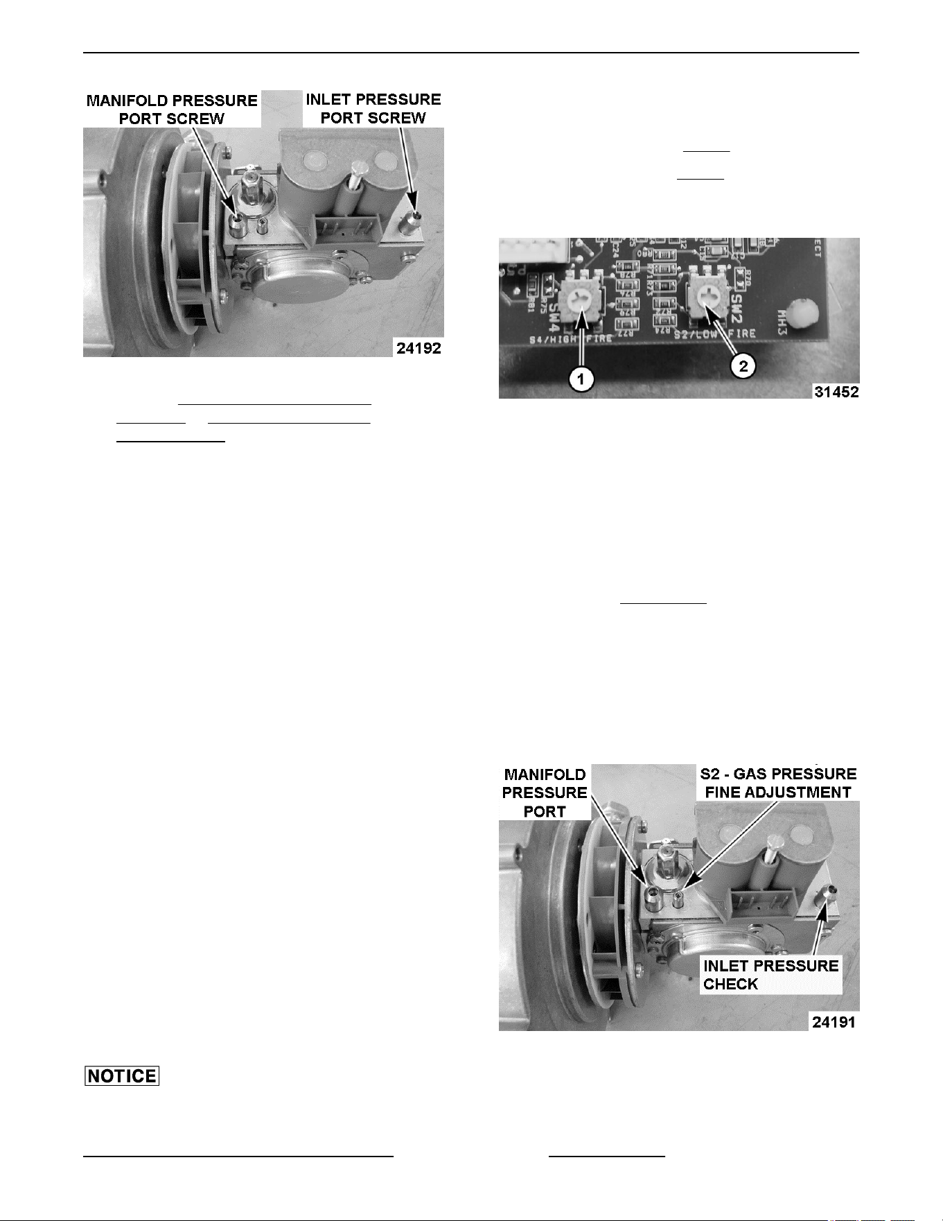
Fig. 49
1. Remove CORNER & REAR PANELS
(TILTING) or SIDE & REAR PANELS
(STATIONARY) to access blower & gas valve.
2. Open inlet pressure port. Turn screw 1 to 2 turns
CCW.
3. Attach slack tube manometer hose to inlet
pressure port.
4. Attach U inclined manometer hose to manifold
pressure port.
5. Turn kettle on.
6. Measure blower vacuum pressure.
A. Blower low speed (during trial for ignition, 7
sec.) - Vacuum pressure reading should be
0.27" W.C. to 0.30" W.C.
B. Blower high speed (15 sec. time delay) -
Vacuum pressure should be 1.91" W.C. to
1.98" W.C.
C. If vacuum pressure reading is outside of the
values stated above, check blower air inlet
for debris buildup / obstructions. If found,
turn power switch off. Remove debris and
retest.
7. Reconnect power and turn gas supply on.
NOTE: If static line pressure exceeds 14" W.C. (½
psig) the customer must supply and install a line
pressure regulator to reduce the pressure below the
maximum allowable for the valve.
8. Turn Kettle on.
9. Verify inlet pressure is 5-7" W.C. (natural) and
11-13" W.C. (propane).
If inlet pressure is excessive, contact the local gas
supply company to adjust incoming line pressure.
10. Verify combustion blower motor speed, control
board settings.
• High Fire = C (1, Fig. 50)
• Low Fire = 8 (2, Fig. 50)
NOTE: The head of the arrow cut out in the center will
designate the rotary switch setting.
Fig. 50
To Adjust:
1. Turn S2 gas pressure fine adjustment screw 1/4
turn (CW to increase; CCW to decrease).
2. Turn power switch off then back on and check
pressure readings. Repeat adjustment as
required.
A. If unable to achieve correct pressure, then
replace
GAS VALVE. Preset S2 - gas
pressure fine adjustment screw on the
replacement valve. Turn screw fully
clockwise until it stops.
Natural - Turn screw 15 turns
counterclockwise.
Propane - Turn screw 9 turns
counterclockwise.
Fig. 51
K Series Gas Kettles 2/3 Jacketed Stationary and Tilting - SERVICE PROCEDURES AND ADJUSTMENTS
Page 27 of 55 F45461 Rev. E (0124)
SPARK IGNITION TEST
If the ignition control module is not generating a spark
or the spark is not sufficient to light kettle burner,
perform the following test.
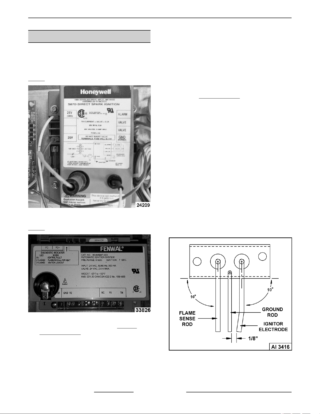
1ST GENERATION IGNITION MODULE SHOWN IN
Fig. 52
Fig. 52
2ND GENERATION IGNITION MODULE SHOWN IN
Fig. 53
Fig. 53
1. Access ignition control module in KETTLE
CONTROL AREA.
2. Turn the on/off switch on and set the temperature
dial to call for heat. Tilting models must be in the
full upright position.
3. Verify the ignition control module is receiving
24VAC between terminals 25V & 25V GND.
A. If voltage is present, turn the on/off switch
off and proceed to step 4.
B. If voltage is not present, see schematic
diagram.
4. Disconnect power to the machine.
5. Verify all electrical connections (including
ground) on the ignition control module are
secure.
6. Access SPARK IGNITOR.
7. Verify the ground connection on spark ignitor is
clean and secure. The ground connection should
have good metal to metal contact.
8. Remove spark ignitor and check the following:
A. Inspect the ceramic insulator on spark
ignitor electrode for cracks or evidence of
exposure to extreme heat, which can permit
leakage to ground. If either of these
conditions exists, then install a replacement
spark ignitor.
B. Inspect the spark ignitor electrode and
ground rod for contaminates, or corrosion.
Clean those surfaces as necessary.
C. Spark gap between the spark ignitor
electrode and ground rod should be
approximately 1/8". If the gap is outside of
this dimension, bend the spark ignitor
electrode as necessary, to make the
adjustment.
Fig. 54
D. Check the ignitor wire connection for
tightness and damaged insulation. If the
ignitor wire appears to be damaged, then
install a replacement ignitor wire.
K Series Gas Kettles 2/3 Jacketed Stationary and Tilting - SERVICE PROCEDURES AND ADJUSTMENTS
F45461 Rev. E (0124) Page 28 of 55
9. Install spark ignitor and reconnect ignitor wire.
FLAME SENSE CURRENT TEST
NOTE: You must complete the SPARK IGNITION
TEST prior to checking flame sense current.
If kettle burner lights but will not maintain flame,
perform the following test.
1. Turn the on/off switch off.
2. Access ignition control module in KETTLE
CONTROL AREA.
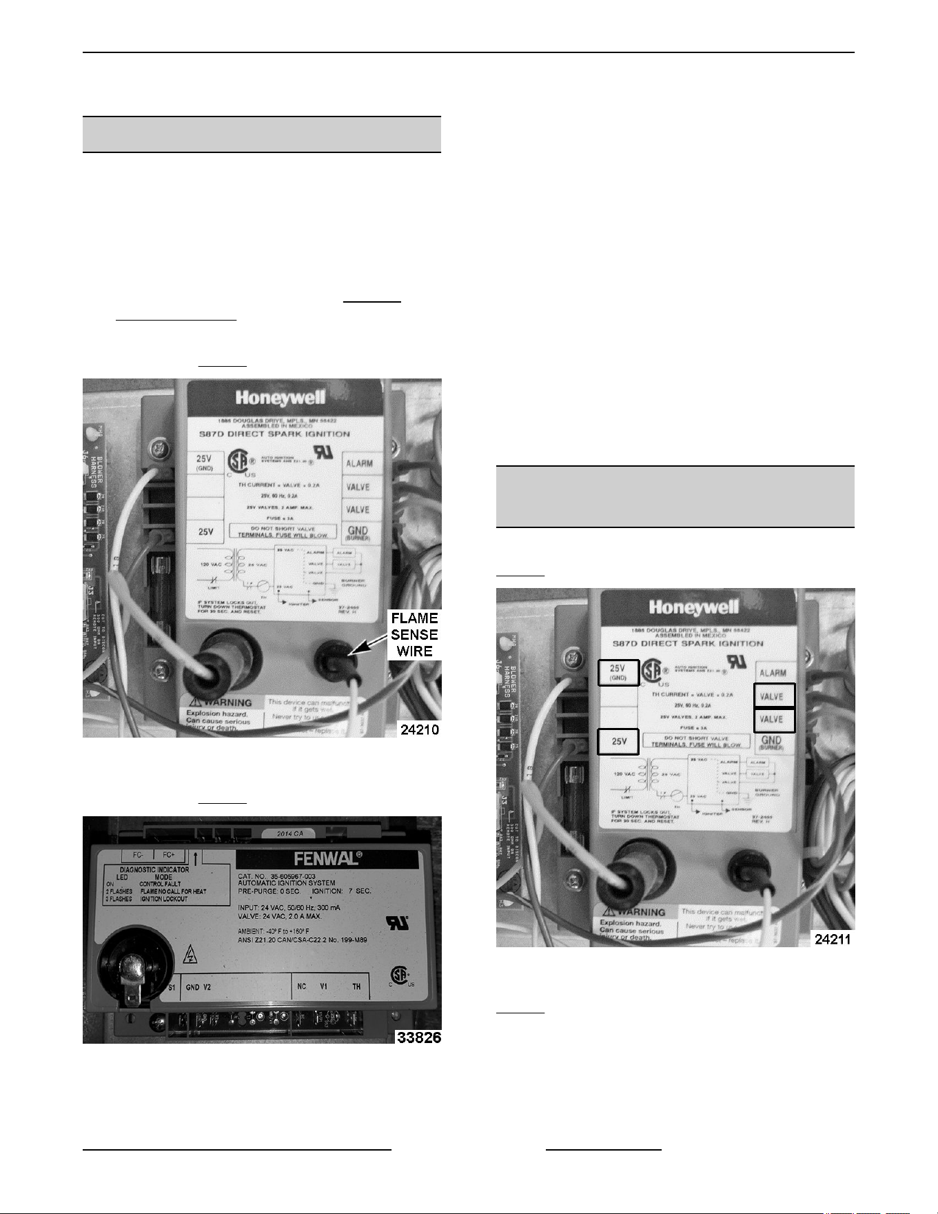
1ST GENERATION IGNITION MODULE
SHOWN IN Fig. 55
Fig. 55
2ND GENERATION IGNITION MODULE
SHOWN IN Fig. 56
Fig. 56
3. Set VOM to micro amps scale (DC). Remove
flame sense wire from ignition module and
connect it to the black meter lead (-) and connect
red meter lead (+) to flame sense terminal.
4. Turn on/off switch on and set the temperature dial
to call for heat.
5. With kettle burner lit, meter reading should be
above 1.5 micro amps (minimum) and steady.
A. If reading is greater than or equal to 1.5
micro amps then flame sense current is
within tolerance. Turn on/off switch off and
reconnect flame sense wire.
B. If reading is less than 1.5 micro amps and
the condition of the spark ignitor and flame
sense has been verified as good, turn on/off
switch off. Install a replacement ignition
control module and check for proper
operation.
IGNITION CONTROL MODULE
TEST
1ST GENERATION IGNITION MODULE SHOWN IN
Fig. 57
Fig. 57
2ND GENERATION IGNITION MODULE SHOWN IN
Fig. 58
K Series Gas Kettles 2/3 Jacketed Stationary and Tilting - SERVICE PROCEDURES AND ADJUSTMENTS
Page 29 of 55 F45461 Rev. E (0124)
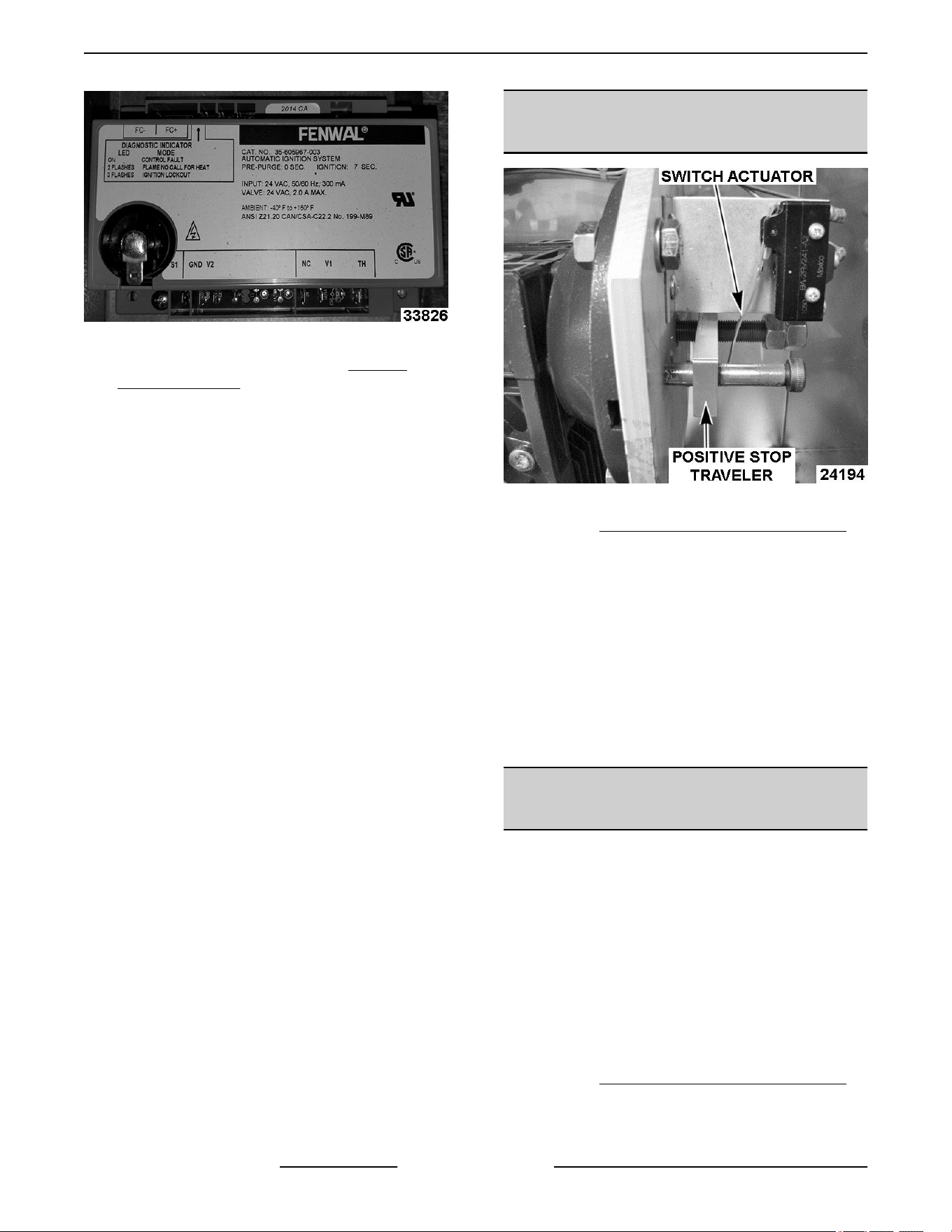
Fig. 58
1. Access ignition control module in KETTLE
CONTROL AREA.
2. Turn the on/off switch on and set the temperature
dial to call for heat.
A. Power (1LT) light and heat light (3LT) come
ON.
3. Ignition control module is energized and trial for
ignition starts (6 seconds).
A. Verify 24VAC between terminals 25V & 25V
GND. If voltage is not present, check
transformer (1T) output voltage.
4. Spark voltage is sent from spark terminal to the
spark ignitor electrode and sparking begins. At
the same time, the ignition module contacts close
to energize gas valve coils, allowing gas flow to
the burner. The kettle burner will light, burner
flame is sensed and spark voltage from spark
terminal is removed (sparking stops).
A. Verify 24VAC between terminals valve and
valve. If voltage is not present, replace
ignition control module and check for proper
operation.
5. As long as the temperature controller is calling for
heat and the ignition control module is sensing a
sufficient flame sense current, the valve contacts
will remain closed.
NOTE: If kettle burner does not immediately light, the
ignition control module continues sparking for 6
seconds, then locks out power to the gas valve (main
valve remains closed). The ignition fail light comes
ON. The module remains locked out until the on/off
switch is cycled to reset the system and re-start the
ignition trial cycle.
TILT SWITCH (2S) ADJUSTMENT -
MANUAL TILTING MODELS
Fig. 59
1. Remove CONTROL BOX COVER (TILTING) to
access Tilt Switch (2S).
2. Kettle tilt operation - The switch actuator should
be operated by the positive stop traveler when
the kettle is fully upright.
3. If adjustment is necessary, bend the switch
actuator to obtain the proper tilt switch operation.
A. Kettle fully upright - Tilt switch should be
operated (N.O. held closed).
B. Kettle tilted approximately 10 degrees - Tilt
switch should be un- operated (open).
KETTLE TILT ADJUSTMENT -
MANUAL TILTING MODELS
NOTE: Perform this procedure whenever the kettle is
not returning to a horizontal position when upright, or
when kettle is not tilting past 90° to empty contents.
1. With kettle fully upright, the top of kettle should
be horizontal when viewed from either side.
2. Turn crank handle clockwise to tilt the kettle until
it stops. Kettle should be tilted past 90° to allow
contents to drain.
3. If adjustment is necessary, continue with
procedure.
4. Remove CONTROL BOX COVER (TILTING).
5. Return kettle to fully upright position.
K Series Gas Kettles 2/3 Jacketed Stationary and Tilting - SERVICE PROCEDURES AND ADJUSTMENTS
F45461 Rev. E (0124) Page 30 of 55
A. The inner jam nut should be in solid contact
with positive stop traveller.
B. To adjust upright position (horizontal):
1) Loosen outer jam nut 2 to 3 turns
counterclockwise and turn the inner
jam nut in the same direction and
amount.
2) Turn crank handle to position the top of
kettle horizontally.
3) Turn inner jam nut clockwise until it
stops against the positive stop
traveller. Tighten outer jam nut to
secure the stop position.
C. Turn crank handle to verify operation.
Repeat adjustment as necessary.
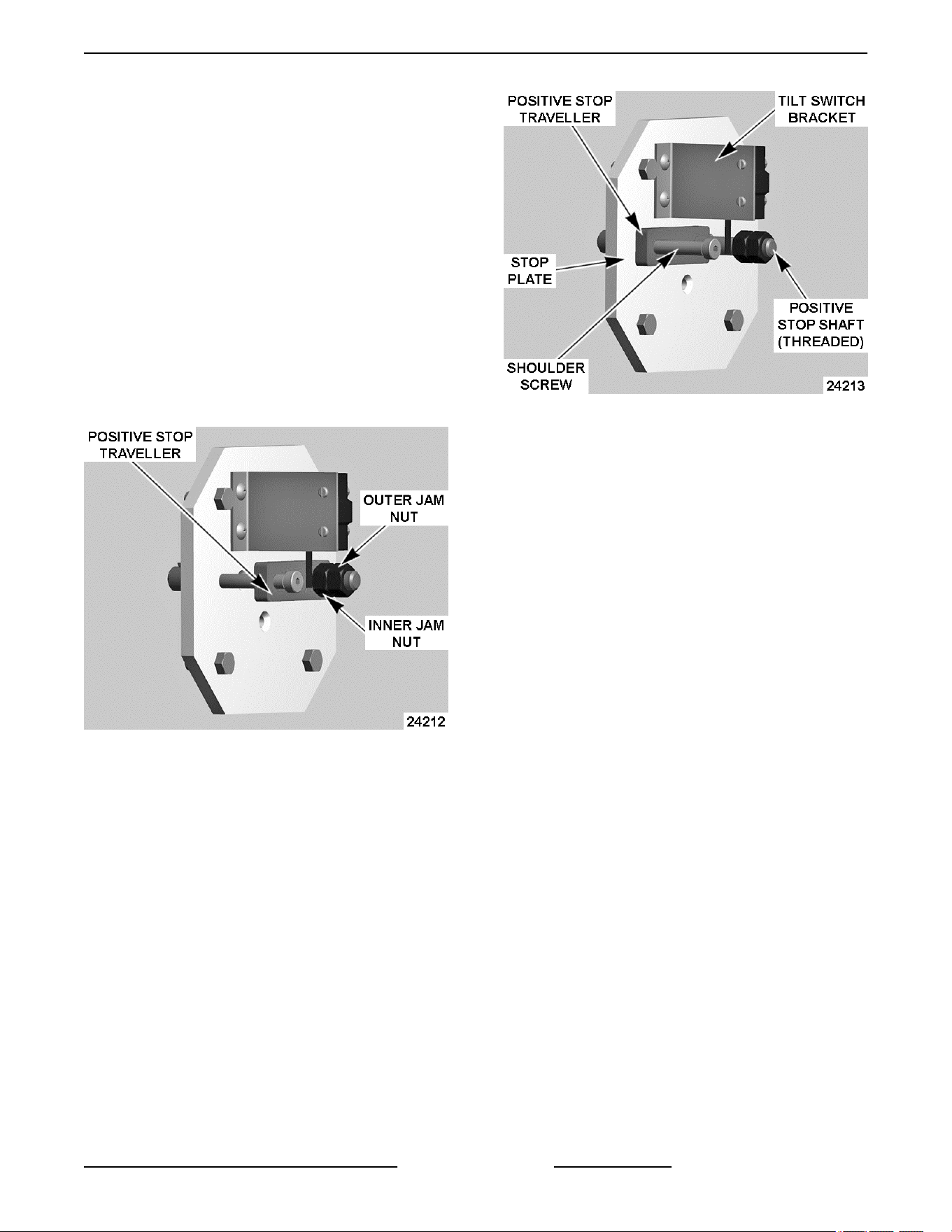
Kettle Fully Upright - Traveller Contacts Inner Jam
Nut
6. Fully tilt the kettle until crank handle stops.
A. Verify positive stop traveller is in solid
contact with stop plate.
B. To adjust fully tilted position:
1) Remove shoulder screw from stop
plate.
2) Remove tilt switch bracket from stop
plate.
Kettle Fully Tilted - Traveller Contacts Stop Plate
3) Turn crank handle clockwise to tilt the
kettle. The kettle should be tilted past
90° to empty its contents. The
adjustment range is 92 to 95 degrees.
4) Turn positive stop traveller on the
positive stop shaft (threaded) until it
contacts the stop plate.
5) Adjust position of positive stop traveller
as needed to align the shoulder screw
mounting hole to the threaded hole in
stop plate. Install shoulder screw.
6) Turn crank handle to verify operation.
Repeat adjustment as necessary.
7) Install tilt switch bracket.
7. Install control panel cover.
K Series Gas Kettles 2/3 Jacketed Stationary and Tilting - SERVICE PROCEDURES AND ADJUSTMENTS
Page 31 of 55 F45461 Rev. E (0124)
TILT SWITCH (2S) ADJUSTMENT -
POWER TILTING OPTION ONLY
Fig. 62
1. Remove CONTROL BOX COVER (TILTING) to
access Tilt Switch (2S).
2. Kettle tilt operation - The switch actuator should
be operated by the arm when the kettle is fully
upright to open the N.C. contacts and stop travel.
3. If adjustment is necessary, loosen the tilt switch
mounting bracket screws (2) and position the
switch to obtain the proper tilt switch operation.
The mounting bracket holes are slotted to allow
for adjustment.
A. Kettle fully upright - Tilt switch should be
operated (N.O. held closed).
B. Kettle tilted approximately 10 degrees - Tilt
switch should be un-operated to remove
power from control circuit through the N.O.
contacts. The N.C. contacts should be
closed to energize K3 and allow kettle to be
raised when tilt motor switch is operated.
4. Tighten switch mounting bracket screws and
check for proper operation.
DOWN LIMIT SWITCH (3S)
ADJUSTMENT - POWER TILTING
OPTION ONLY
Fig. 63
1. Remove CONTROL BOX COVER (TILTING) to
access Down Limit Switch (3S).
2. Kettle tilt operation - The switch actuator should
be operated by the arm when the kettle is tilted
past 90° to open the switch contacts and stop
travel. The adjustment range is 92 to 95 degrees.
3. If adjustment is necessary, tilt kettle as described
above and stop travel.
A. Loosen the down limit switch mounting
bracket screws (2) and position the switch
to obtain the proper down limit switch
operation. The mounting bracket holes are
slotted to allow for adjustment.
4. Tighten switch mounting bracket screws and
check for proper operation.
DC TILT MOTOR CONTROLLER
TEST - POWER TILTING OPTION
ONLY
1ST GENERATION CONTROLLER BOARD
SHOWN IN Fig. 64
K Series Gas Kettles 2/3 Jacketed Stationary and Tilting - SERVICE PROCEDURES AND ADJUSTMENTS
F45461 Rev. E (0124) Page 32 of 55
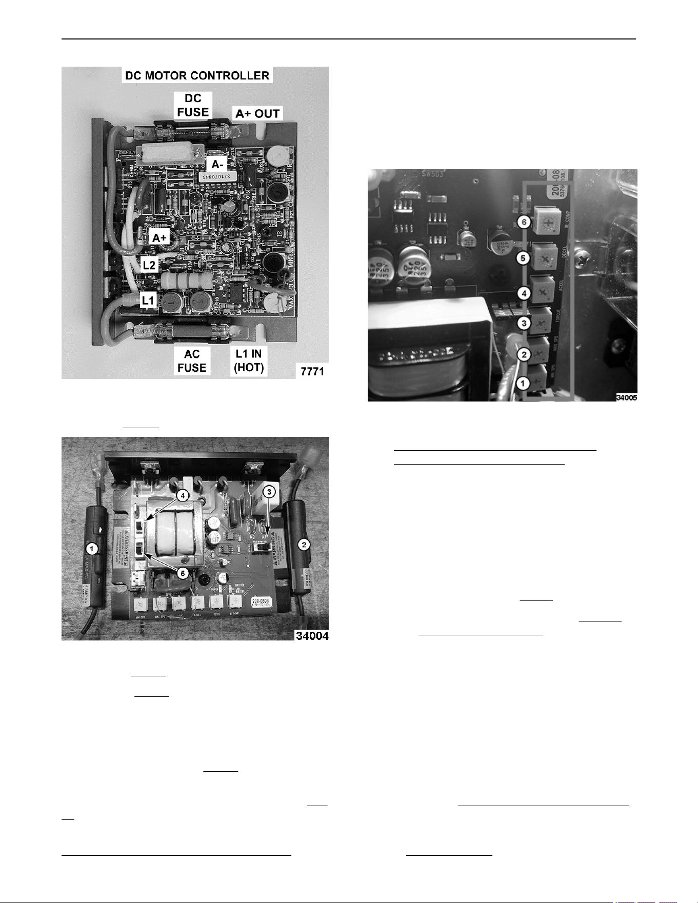
Fig. 64
2ND GENERATION CONTROLLER BOARD
SHOWN IN Fig. 65
Fig. 65
• Fuse - 1,Fig. 65, 4 amp AC.
• Fuse - 2, Fig. 65, 2 amp DC.
• Switches
• 4 and 5 switches shown in are both set at
115V.
• 3 switch shown in Fig. 65 should be set at
90.
Trimpots 2nd Generation Controller Board in Fig.
66
• 1) MIN SPD set to 5 o’clock.
• 2) MAX SPD set to 5 o'clock.
• 3) TORQUE set to 5 o'clock.
• 4) ACCEL set to 12 o'clock.
• 5) DECEL set to 12 o'clock.
• 6) IR COMP set to 12 o'clock.
Fig. 66
1. Access DC tilt motor controller. Refer to:
ELECTRICAL PANEL COMPONENTS -
POWER TILTING OPTION ONLY.
Set VOM to measure AC volts and connect meter
leads at L1 & L2 on controller.
2. Turn power switch on.
3. Verify 120VAC at L1 & L2 on controller when the
tilt motor switch (momentary) is operated to lower
and raise kettle.
A. If voltage is present but kettle does not raise
& lower, proceed to Step 5.
B. If voltage is not present refer to POWER
TILTING OPTION ONLY.
4. Disconnect power to machine.
5. Set VOM to measure DC volts and connect VOM
leads to terminals A + (positive) & A - (negative)
on controller.
6. Re-connect power to the machine.
7. Verify 90VDC (approximate) from DC tilt motor
controller when the tilt motor switch (momentary)
is operated to raise & lower pan.
A. If voltage is present but pan does not raise,
refer to POWER TILTING OPTION ONLY.
K Series Gas Kettles 2/3 Jacketed Stationary and Tilting - SERVICE PROCEDURES AND ADJUSTMENTS
Page 33 of 55 F45461 Rev. E (0124)
B. If voltage is not present and DC fuse is ok,
turn power switch off and disconnect power
to machine.
8. Install a replacement DC tilt motor controller and
check for proper operation.
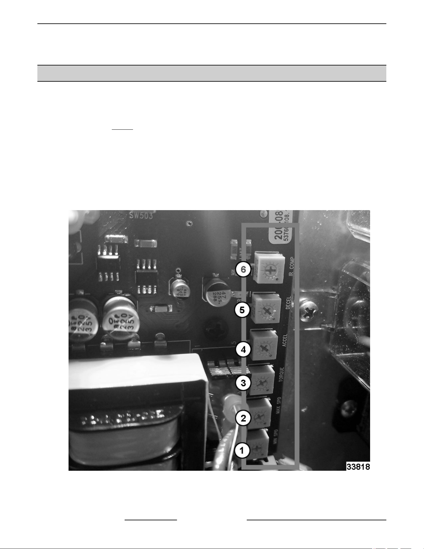
SETTING RESISTOR ON CONTROLLER SPEED BOARD
Dial in Resistor
1. Turn all dial settings (white squares) on board all the way to the left.
2. Dial in all settings (Fig. 67).
• 1) MIN SPD set to 12 o’clock.
• 2) MAX SPD set to 11 o'clock.
• 3) TORQUE set to 11 o'clock.
• 4) ACCEL set to 1 o'clock.
• 5) DECEL set to 1 o'clock.
• 6) IR COMP set to 12 o'clock.
Fig. 67
K Series Gas Kettles 2/3 Jacketed Stationary and Tilting - SERVICE PROCEDURES AND ADJUSTMENTS
F45461 Rev. E (0124) Page 34 of 55
FILLING THE RESERVOIR JACKET
NOTE: The reservoir water level must be maintained high enough to keep contact with the water level probe
(LLCO). If low water light comes on during use, the visible level may be below the water level probe and must be
replenished before heating can continue. The low water light will come on when kettle is tilted (tilting models only).
When filling reservoir jacket, use only distilled water and heat transfer fluid. The ratio is 2:1, 2 parts distilled water,
1 part Heat Transfer Fluid.
NOTE: Jacket fill port plumbing: A pipe elbow and pipe plug are installed on current construction kettles to open
the fill port. A manual valve with knob was installed on previous construction kettles to open the fill port.
Partial Refill
1. Place kettle in full upright position (tilting models only).
Fig. 68
2. Turn power switch on.
If Low water light is lit on control panel, continue with procedure to refill.
3. Set temperature dial to lowest setting.
Pressure Relief Valve Exhaust. DO NOT connect to building water, gas, or steam supply. DO NOT block
or restrict.
Hot steam. The kettle and its parts are hot. Use care when operating, cleaning or servicing the kettle.
4. Open pressure relief valve until reservoir jacket is completely vented. Allow valve to snap shut to seal.
5. If installed, open the manual valve on the fill port for the reservoir jacket at back of kettle.
K Series Gas Kettles 2/3 Jacketed Stationary and Tilting - SERVICE PROCEDURES AND ADJUSTMENTS
Page 35 of 55 F45461 Rev. E (0124)
A. Remove pipe plug from the valve/pipe elbow to open the fill port.
B. Insert funnel into the fill port and slowly add water until the level in the sight glass is 1/3 full. Low water
light should be off (LLCO probe is satisfied). As necessary, vent the air from the jacket as outlined below:
1) If pressure relief valve is installed at a separate location from the fill port (two different openings in
the jacket), open the pressure relief valve to provide a vent for the jacket air to escape and aid in
filling. Allow valve to snap shut to seal.
2) If pressure relief valve and fill port are installed on the same plumbing assembly (single opening to
the jacket), access the Pressure Switch (1PS), remove the compression nut from fitting near the tee
and pull the tubing from the fitting.
C. Turn power switch off.
NOTE: Heat Transfer Fluid: Thermodyne 90395 GLYCOL, Heat Transfer Fluid, 1 gallon, available at Parts
Town or DOWFROST™ Propylene Glycol at ChemWorld.
6. Close manual valve (if installed) to prevent leaks. Hand tighten only.
7. Clean pipe plug threads and apply thread sealant. Install pipe plug into valve/pipe elbow opening to close the
fill port. Tighten to prevent leaks.
8. Turn power switch on and verify low water light is not lit. Refer to: RESERVOIR JACKET VOLUME TABLE
A. If low water light is lit, see Possible Causes for LOW WATER LIGHT LIT in TRTROUBLESHOOTING.
B. If low water light problem is still not resolved see Possible Causes for KETTLE DOES NOT HEAT in
TROUBLESHOOTING.
9. Remove air from reservoir jacket as outlined under VENTING.
10. Check kettle for proper operation.
RESERVOIR JACKET VOLUME
Model Water (Qt)
Heat Transfer
Fluid
Food Grade
Antifreeze (Qt)
Total (Qt)
Low Level
Light OFF
Low Level
To Fill
K20GL,
K20GLT
24 12 36 16 quarts 20 quarts
K40GL,
K40GLT
18 10 28 18 quarts 10 quarts
K60GL,
K60GLT
30 14 44 24 quarts 20 quarts
K Series Gas Kettles 2/3 Jacketed Stationary and Tilting - SERVICE PROCEDURES AND ADJUSTMENTS
F45461 Rev. E (0124) Page 36 of 55

Complete Draining and Refill
Disconnect the electrical power to the machine and follow lockout / tagout procedures.
Pressure Relief Valve Exhaust. DO NOT connect to building water, gas, or steam supply. DO NOT block or
restrict.
Hot steam. The kettle and its parts are hot. Use care when operating, cleaning or servicing the kettle.
NOTE: Appearance of fluid will no longer be clear after usage in kettle.
1. Set temperature dial to lowest setting.
2. Open pressure relief valve until reservoir jacket is completely vented. Allow valve to snap shut to seal.
3. Remove pressure relief valve from kettle to vent the jacket and facilitate draining. Retain for reuse.
4. Remove draw-off valve or plug valve from kettle (stationary models only).
5. Place container under kettle to catch fluid and position it below the sight glass.
6. Remove sight glass using 36mm socket.
A. Stationary Models - It is recommended to use a drill pump to drain.
B. Tilting Models - Turn crank handle clockwise to tilt the kettle forward.
7. After draining is complete, place kettle in full upright position.
A. Install sight glass and tighten it to seal the internal O-ring to prevent leaks.
8. To Refill.
A. With kettle in full upright position.
B. If installed, open the manual valve on the fill port for the reservoir jacket at back of kettle.
C. Remove pipe plug from valve/pipe elbow to open the fill port.
D. Insert funnel into the fill port and slowly add mixture of water and heat transfer fluid to the reservoir jacket.
Fill the jacket according to the volumes listed in the table below. The level in the sight glass should be
1/3 full. Refer to: RESERVOIR JACKET VOLUME TABLE
9. Close manual valve (if installed) to prevent leaks. Hand tighten only.
10. Clean pipe plug threads and apply thread sealant. Install pipe plug into valve/pipe elbow opening to close the
fill port. Tighten to prevent leaks.
11. Install pressure relief valve to kettle.
12. Install draw-off valve or plug valve to kettle (stationary models only).
13. Re-connect power.
14. Turn power switch on and verify low water light is not lit.
A. If low water light is lit, see Possible Causes for LOW WATER LIT in .
B. If low water light problem is still not resolved see Possible Causes for KETTLE DOES NOT HEAT in
TROUBLESHOOTING.
K Series Gas Kettles 2/3 Jacketed Stationary and Tilting - SERVICE PROCEDURES AND ADJUSTMENTS
Page 37 of 55 F45461 Rev. E (0124)

15. Remove air from reservoir jacket as outlined under VENTING.
16. Check kettle for proper operation and leaks.
RESERVOIR JACKET VOLUME
Model Water
Heat Transfer Fluid
Food Grade Antifreeze
Total
K20GL, K20GLT 24 quarts 12 quarts 36 quarts
K40GL, K40GLT 18 quarts 10 quarts 28 quarts
K60GL, K60GLT 30 quarts 14 quarts 44 quarts
K Series Gas Kettles 2/3 Jacketed Stationary and Tilting - SERVICE PROCEDURES AND ADJUSTMENTS
F45461 Rev. E (0124) Page 38 of 55

ELECTRICAL OPERATION
COMPONENT FUNCTION (STATIONARY & TILTING MODELS)
Water Level Control
(WLC LLCO) ..........
Low water level control. Monitors condition of the WLC LLCO water level probe. Protects
kettle from a low water condition in the reservoir jacket.
Probe, Water Level
(LLCO) ................
Low Level Cut-Off (LLCO) probe connected to WLC (LLCO). Controls power to heating
circuit.
Fuse, (1FU) ........... Time delay 4 amp - 250v fuse. Located on L1 of machine supply power. Protects control
circuitry from over-currents.
Switch (1PAS),
Pressure ..............
Pressure cut-out protection for the reservoir jacket. Range is 38 to 42 PSI. Removes
power from control circuit if pressure in the jacket rises above switch setting.
Transformer (1T) ..... Steps down the supply voltage to 24VAC (control circuit voltage).
Switch (1S), Power ... Controls 120VAC to kettle control circuit
Switch (2S), Tilt ....... Tilting models only. N.O. switch contacts are held closed when kettle is in the upright
position and will open to remove power from control circuit when kettle is tilted. With kettle
tilted, the N.C. switch contacts return to the closed position and energize K3 raise-enable
relay coil.
Temperature
Controller .............
Cycles power to blower motor (1MOT), heat lamp (3LT) and transformer (1T). Allows
ignition control circuit to energize and light the burner to maintain set point temperature.
An external set point potentiometer is used for temperature adjustments.
Gas Shut-Off Valve
(1SOL) ................
Tilting models only. Additional solenoid valve to shut off the gas supply and remove line
pressure on the special gas line fittings that run through gear box (when kettle is not in
use). This increases seal life on the special fittings.
Timer (1TMR), Delay
on Make ..............
Provides a 15 second delay before energizing relay K4.
Relay, K4 ............. Relay contacts provide 24VAC input signal to blower speed control connector pins (J5.4
or J5.3) for blower motor low and high speed operation.
Relay, Raise-Enable,
K3 ....................
Power tilting option only. Allows kettle to raise when the tilt switch (2S) is un-operated
( kettle tilted) and K3 raise-enable N.O. contacts are closed. K3 relay coil is energized
through the N.C. contacts on tilt switch (2S).
Blower Speed
Control ...............
Controls blower motor speed via a 24VDC pulse width modulation (PWM) signal to the
blower motor. 24VAC voltage signal to the control and the control's switch settings (S1,
SW2 & SW4) determine low speed or high speed blower operation.
Blower Motor
(1MOT) ................
Draws gas from the gas valve outlet into the blower housing for the gas/air mixture
delivered to the burner.
Gas Valve ............. Regulates gas line supply pressure down to atmospheric pressure level and functions as
a "zero pressure regulator". The dual solenoid valve (1 main; 1 safety backup) is attached
at the air inlet on the blower motor housing. Gas valve receives power from ignition
module.
Ignition Module ....... Controls and monitors burner ignition. Energizes main valve coil and generates spark for
burner ignition. Monitors the presence of flame. Includes an accessible fast acting 3 amp
- 250v fuse to protect ignition module.
Ignitor/Flame
Sense .................
Ignites the gas burner and senses the presence of flame. The flame presence generates
a micro-amp flame sense current that is rectified to the ignition module.
Light (1LT), Power .... Amber (AM) colored light. On when power switch is on.
K Series Gas Kettles 2/3 Jacketed Stationary and Tilting - ELECTRICAL OPERATION
Page 39 of 55 F45461 Rev. E (0124)

Light (2LT), Low
Water .................
Red (RD) colored light. On when water level in the reservoir jacket drops below water
level (LLCO) probe.
Light (3LT), Heat ...... Amber (AM) colored light. On when temperature controller is calling for heat.
Ignition Fail (4LT) ..... Amber (RD) colored light. On when burner does not light.
COMPONENT FUNCTION (POWER TILTING OPTION)
DC Tilt Motor
Controller .............
Controls DC tilt motor operation to tilt the kettle and provides motor acceleration control
each time the controller is powered. The controller outputs approximately 90VDC to
power the motor.
DC Tilt Motor ......... Operates gear reducer to tilt the kettle. When the correct voltage polarity is applied
through K1 contacts, motor rotates CW to raise the kettle. When reverse voltage polarity
is applied through K2 contacts, motor rotates CCW to tilt the kettle. Rotation direction as
viewed from shaft end.
Transformer (2T) ..... Steps down supply voltage to 24VAC (power tilt circuit voltage).
Tilt Motor Switch
(Momentary On/Off/
On) ...................
Energizes K1 relay coil thru K3 raise-enable contacts (N.O.) to raise the kettle. Energizes
K2 relay coil thru down limit switch contacts (N.C.) to tilt the kettle. The switch positions
are: Center neutral (starting) position off; Momentary on - tilt kettle; Momentary on - raise
kettle.
Down Limit Switch .... N.C. contacts function as down limit switch to remove power from K2 relay coil when
kettle is fully tilted (travel stops).
K1 "Up" Relay
(3PDT) ................
Supplies power to motorized tilt circuit to raise the kettle when 24VAC coil is energized.
K2 "Down" Relay
(3PDT) ................
Supplies power to motorized tilt circuit to tilt the kettle when 24VAC coil is energized by
the tilt control switch. The voltage polarity to the DC motor is reversed through K2 contacts
to turn motor CW and tilt the kettle.
K Series Gas Kettles 2/3 Jacketed Stationary and Tilting - ELECTRICAL OPERATION
F45461 Rev. E (0124) Page 40 of 55
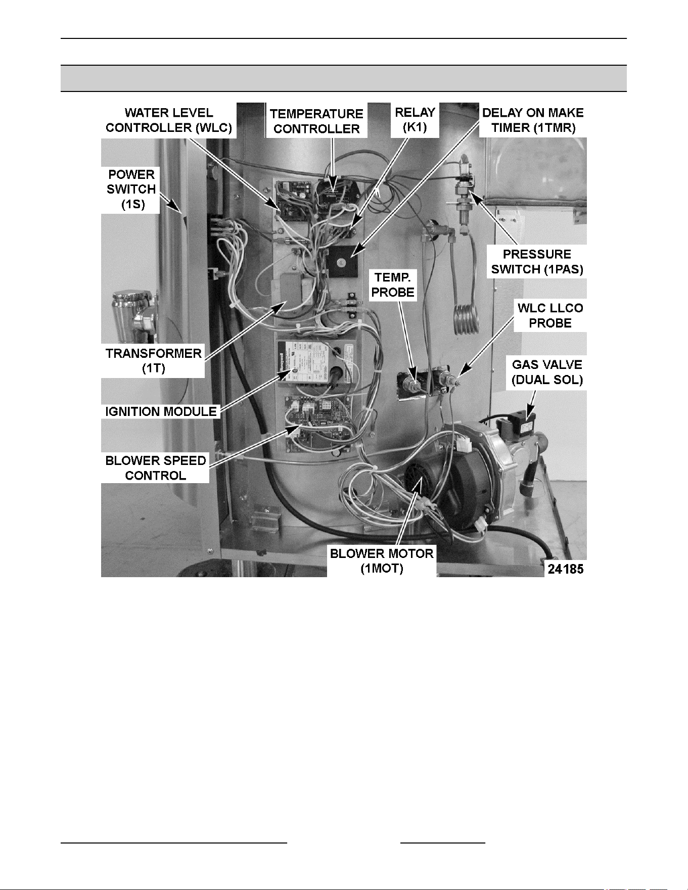
COMPONENT LOCATION (STATIONARY & TILTING MODELS)
K Series Stationary Gas Kettle - Controls Side
K Series Gas Kettles 2/3 Jacketed Stationary and Tilting - ELECTRICAL OPERATION
Page 41 of 55 F45461 Rev. E (0124)
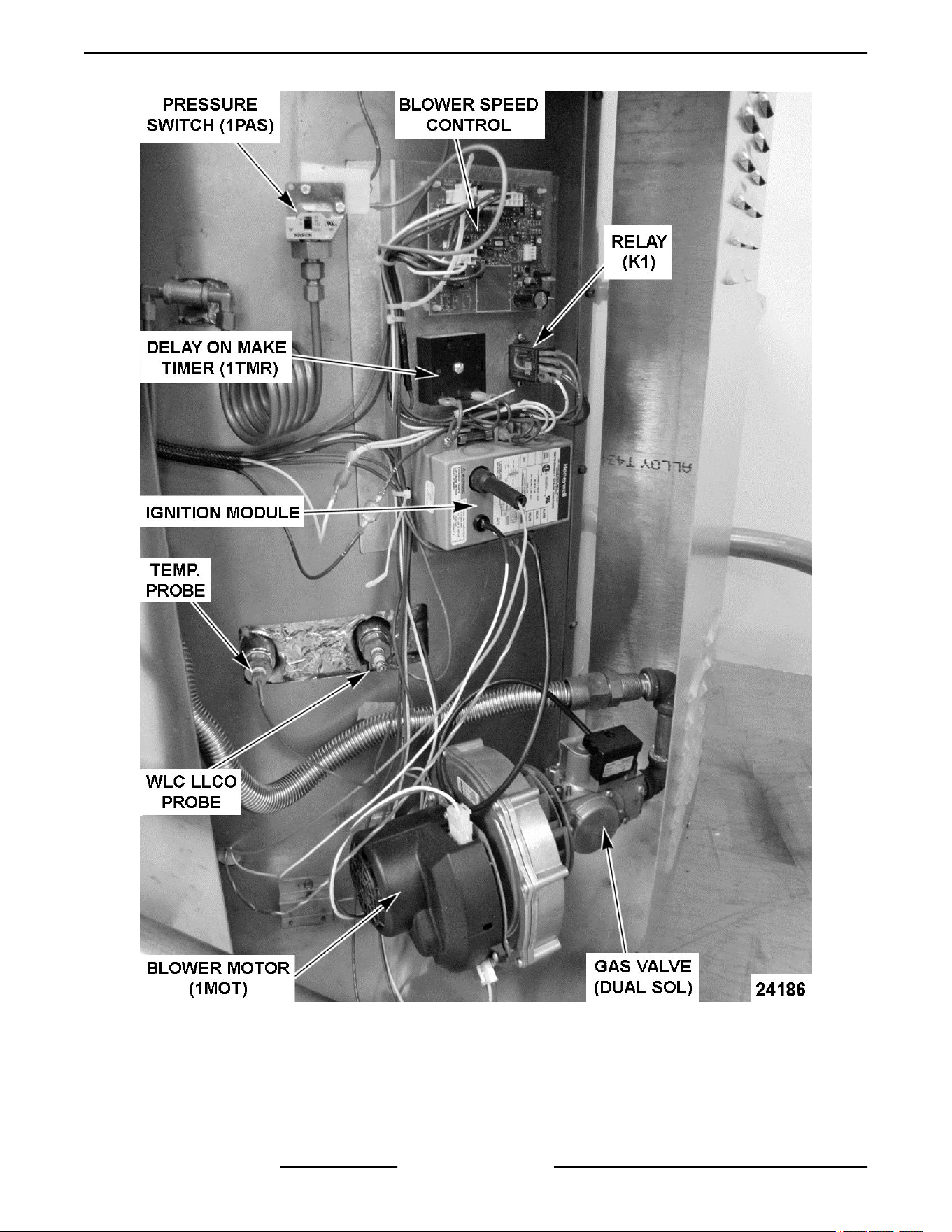
K Series Tilting Gas Kettle - Controls Side
K Series Gas Kettles 2/3 Jacketed Stationary and Tilting - ELECTRICAL OPERATION
F45461 Rev. E (0124) Page 42 of 55
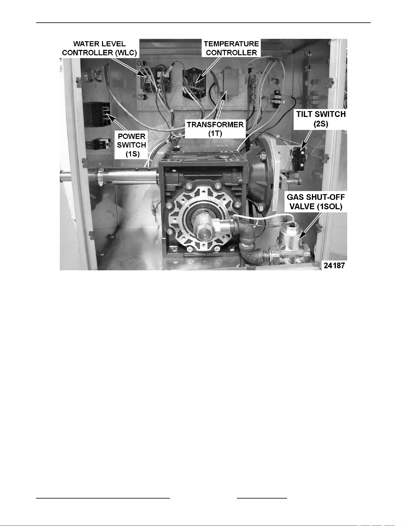
K Series Manual Tilt Gas Kettle - Control Box Area
K Series Gas Kettles 2/3 Jacketed Stationary and Tilting - ELECTRICAL OPERATION
Page 43 of 55 F45461 Rev. E (0124)
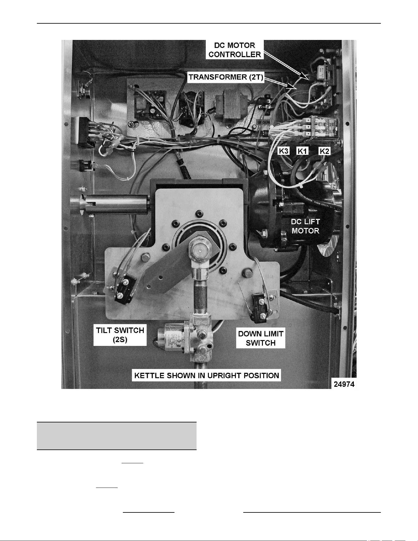
K Series Gas Kettle with Power Tilt Option - Control Box Area
SEQUENCE OF OPERATION
(KETTLE CONTROL CIRCUIT)
Refer to Schematic diagram AI3537 for stationary and
manual tilting kettle models. Kettles with Power Tilt,
refer to Sequence of Operation - Power Tilt Option and
schematic diagram AI3538.
1. Conditions.
A. Kettle connected to 120VAC supply and is
properly grounded.
B. Kettle connected to correct gas supply and
the supply is on.
C. Power switch (1S) and light (1LT) (amber)
are off.
D. Low water light (2LT) (red) is off.
K Series Gas Kettles 2/3 Jacketed Stationary and Tilting - ELECTRICAL OPERATION
F45461 Rev. E (0124) Page 44 of 55

E. Tilt switch (2S) operated, N.O. contacts held
closed (kettle in the full upright position -
tilting models only).
F. Pressure switch (1PAS) N.C. contacts are
closed.
G. Temperature dial at lowest setting
(potentiometer fully CCW).
1) Internal relay N.O. contacts are open.
H. Kettle at room temperature.
2. Power switch ON.
A. Power provided to the power tilt circuit
(kettels with power tilt option only).
B. Power light (1LT) (amber) comes on.
C. 120VAC to water level controller through tilt
switch (2S) N.O. contacts, held closed
(tilting models only) and pressure switch
(1PAS) N.C. contacts.
3. Water level control (WLC) energized.
A. WLC LLCO probe satisfied (fluid in kettle
reservoir jacket at proper level).
1) LLCO LED comes on.
B. WLC LLCO N.C. contacts open. Low water
light (2LT) (red) remains off.
C. WLC LLCO N.O. contacts close.
1) 120VAC to temperature controller.
4. Set the temperature dial to call for heat (warm/
simmer/boil).
A. 120VAC output from T8 on temperature
controller.
1) Heat light (3LT) (amber) comes on.
2) Blower motor (1MOT) energized.
3) 120/24VAC transformer (1T) primary
energized.
5. 24VAC is output from transformer (1T)
secondary to heating circuit.
A. Gas shut-Off Valve (1SOL) energized (tilting
models only).
B. Delay on make timer (1TMR) is energized
and begins 15 second count down before
output from timer is turned on (will energize
relay K4).
NOTE: Relay K4 contacts provide the 24VAC input
voltage signal to the blower speed control to select
blower motor speed (low or high). The blower speed
control (J6.4) sends a corresponding 24VDC pulse
width modulation (PWM) output signal to the blower
motor for low or high speed operation.
C. Blower speed control powered at connector
J5.4 for blower motor low speed operation
through K4 N.C. contacts. Blower at low
speed.
D. Ignition module energized and trial for
ignition begins. The module generates
spark at ignitor and energizes the dual gas
valve coils to open the valves and provide
gas for the gas/air mixture to light the
burner.
E. Burner lights and kettle heating begins. As
long as the ignition control module senses a
burner flame, the ignition module will
continue to power the gas valve.
1) If burner flame is not sensed within 7
seconds, ignition module stops
sparking, de-energizes gas valve coils
and enters lockout mode.
2) If lockout, ignition fail light (4LT) (red)
comes on.
F. Time expires on delay on make timer
(1TMR). Timer output turns on and relay K4
is energized.
1) K4 N.C. contacts open and remove
power from blower speed control at
connector J5.4 (low speed blower
operation).
2) K4 N.O. contacts close and apply
power to blower speed control at
connector J5.3 (high speed blower
operation). Blower at high speed.
6. Kettle heat cycles with the temperature
controller.
7. On tilting models only, when kettle is tilted to
empty contents the tilt switch (2S) N.O. contacts
open to remove power from control circuit. Tilt
switch (2S) contacts will close when the kettle is
returned to full upright position and resume
normal operation.
A. Power light (1LT) (amber) remains on.
8. Kettle heating will continue to cycle with the
temperature controller until the temperature dial
is turned fully CCW or power switch is turned
OFF.
K Series Gas Kettles 2/3 Jacketed Stationary and Tilting - ELECTRICAL OPERATION
Page 45 of 55 F45461 Rev. E (0124)

SEQUENCE OF OPERATION
(POWER TILTING OPTION)
Refer to schematic diagram AI3538 for power tilting
option and AI3537 for the main control circuit diagram
that includes Tilt Switch (2S) and Raise-Enable relay
(K3).
1. Conditions.
A. 120VAC to kettle, polarity is correct, and is
properly grounded.
B. Power switch off.
C. Tilt motor switch off (center position).
D. Kettle in the upright position.
E. Tilt switch (2S) operated, N.O. contacts held
closed (kettle arm engages switch actuator).
F. K3 raise-enable relay N.O. contacts are
open (raise-enable relay coil is de-
energized).
G. Down limit switch N.C. contacts closed.
2. Power switch on.
A. Power light (1LT) (amber) comes on.
B. 120/24VAC transformer (2T) energized.
Power to tilt motor switch common terminal.
NOTE: If the temperature dial is set to call for heat,
the ignition trial starts and module begins sparking at
ignitor.
3. Operate tilt motor switch to tilt the kettle
(momentary on - tilt).
A. K2 down relay coil is energized through
down limit switch N.C. contacts.
1) K2 4/7 N.O. contacts close.
2) K2 9/6 N.O. contacts close.
3) K2 8/5 N.O. contacts close.
B. 120VAC to DC tilt motor controller through
K2 4/7 N.O. contacts.
1) 90VDC output is activated at terminals
A + (positive) and A - (negative). DC tilt
motor powered through K2 9/6 N.O.
contacts, K2 8/5 N.O. contacts and
kettle tilts.
C. Kettle tilted approximately 10° and tilt switch
(2S) is un-operated (kettle arm disengages
from switch actuator). 2S contacts change
position from N.O. to N.C.
1) With 2S N.O. contacts open - power is
removed from control circuit and
heating stops.
2) With 2S N.C. contacts closed - Raise
enable-relay coil (K3) is energized and
K3 N.O. contacts close. No power is
transferred to K1 up relay until tilt motor
switch is operated to raise the kettle.
4. Kettle reaches full tilt position at approximately
95° and the down limit switch is operated. The
down limit switch N.C. contacts open and K2
relay coil is de-energized.
A. The three sets of K2 N.O. contacts return to
the open position. Power is removed from
the DC motor controller, the DC tilt motor
and kettle travel stops.
5. Operate tilt motor switch to return the kettle
upright (momentary on - raise).
A. K1 up relay coil is energized through raise-
enable (K3) closed contacts.
1) K1 4/7 N.O. contacts close.
2) K1 9/6 N.O. contacts close.
3) K1 8/5 N.O. contacts close.
B. 120VAC to DC tilt motor controller through
K1 4/7 N.O. contacts.
1) 90VDC output is activated at terminals
A + (positive) and A - (negative). DC tilt
motor powered through K1 9/6 N.O.
contacts, K1 8/5 N.O. contacts and
kettle raises.
2) After the kettle leaves full tilt position,
the down limit switch is un-operated
and the switch contacts return to N.C.
position. The direction of kettle travel
can then be reversed (if needed) by tilt
motor switch.
6. Kettle reaches full upright position, the tilt switch
(2S) is operated (kettle arm engages switch
actuator). 2S contacts change position from N.C.
to back to N.O.
A. With 2S N.O. contacts closed - power
restored to control circuit and heating
resumes.
B. With 2S N.C. contacts open - Raise enable-
relay coil (K3) is de-energized and K3 N.O.
contacts open. K1 up relay coil is de-
energized.
K Series Gas Kettles 2/3 Jacketed Stationary and Tilting - ELECTRICAL OPERATION
F45461 Rev. E (0124) Page 46 of 55

C. The three sets of K1 N.O. contacts return to
the open position. Power is removed from
the DC motor controller, the DC tilt motor
and kettle travel stops.
K Series Gas Kettles 2/3 Jacketed Stationary and Tilting - ELECTRICAL OPERATION
Page 47 of 55 F45461 Rev. E (0124)
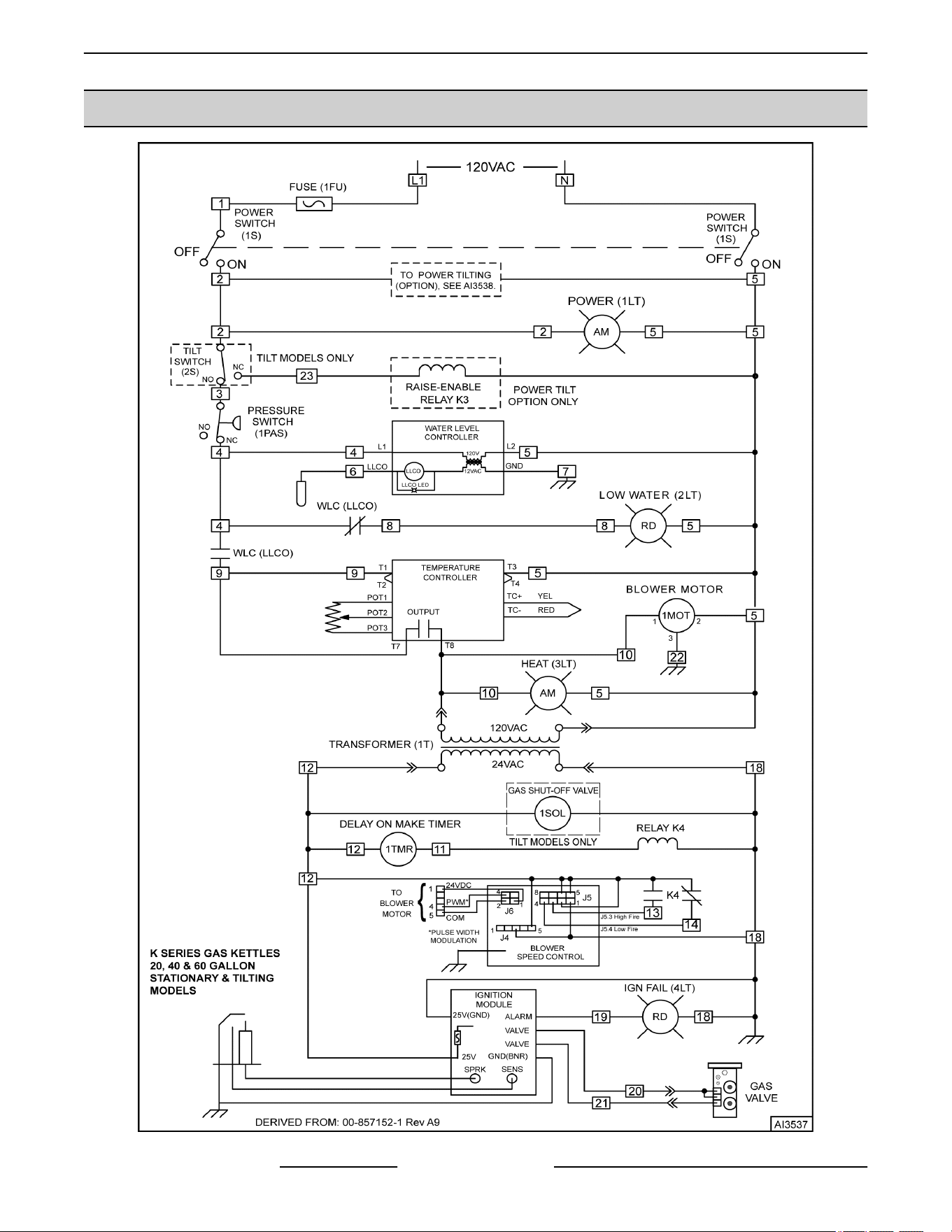
SCHEMATIC DIAGRAM (STATIONARY & TILTING MODELS)
Fig. 73
K Series Gas Kettles 2/3 Jacketed Stationary and Tilting - ELECTRICAL OPERATION
F45461 Rev. E (0124) Page 48 of 55
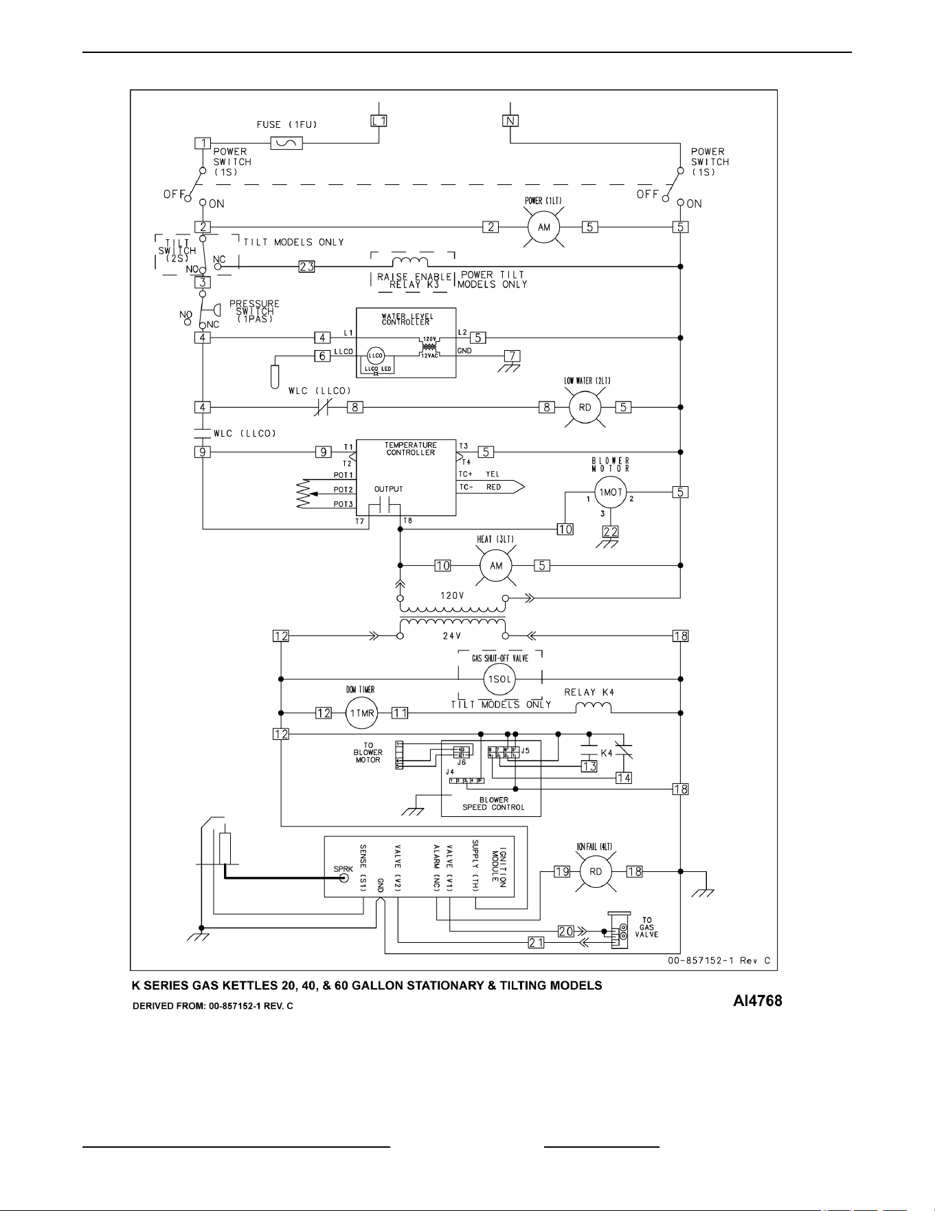
Fig. 74
K Series Gas Kettles 2/3 Jacketed Stationary and Tilting - ELECTRICAL OPERATION
Page 49 of 55 F45461 Rev. E (0124)
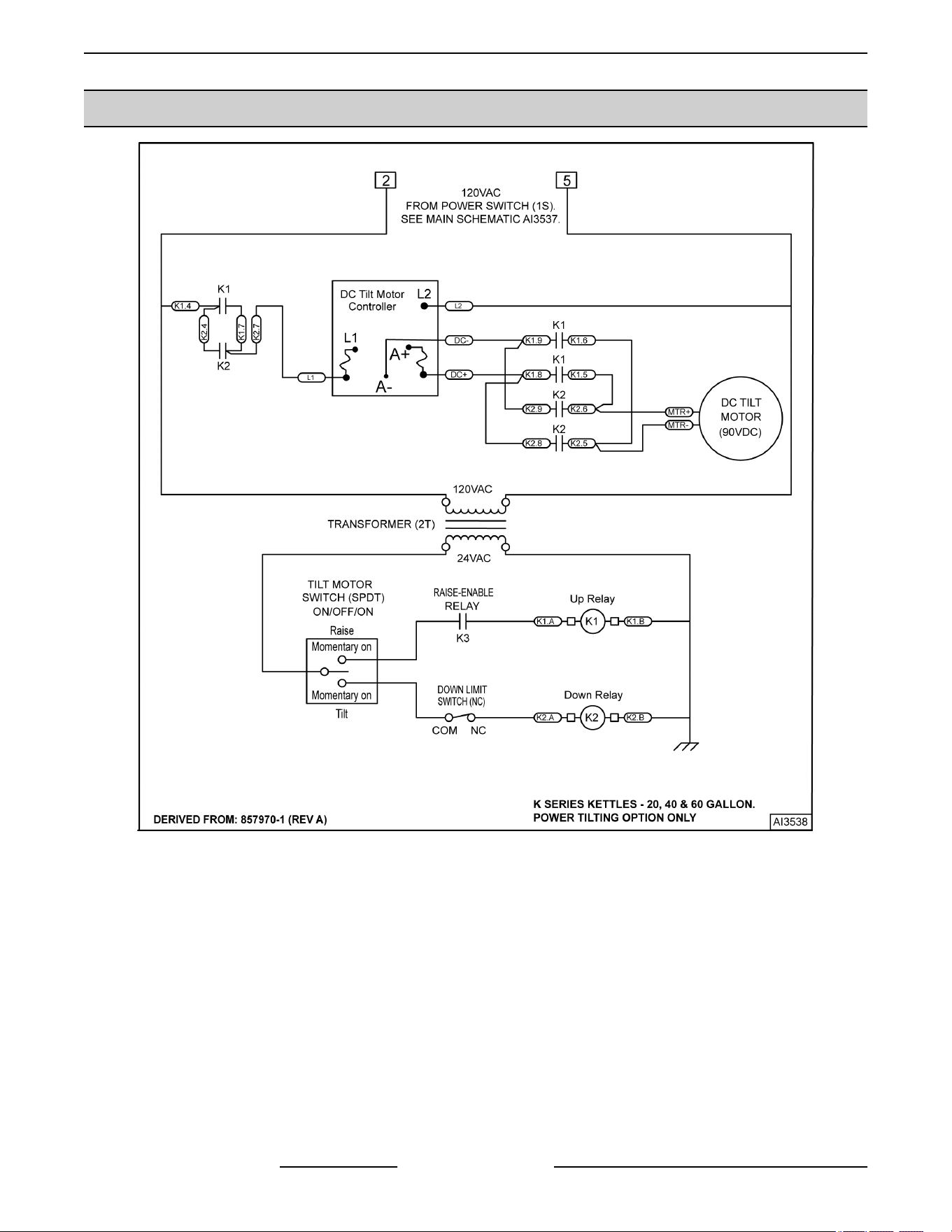
SCHEMATIC DIAGRAM (POWER TILTING OPTION)
Fig. 75
K Series Gas Kettles 2/3 Jacketed Stationary and Tilting - ELECTRICAL OPERATION
F45461 Rev. E (0124) Page 50 of 55
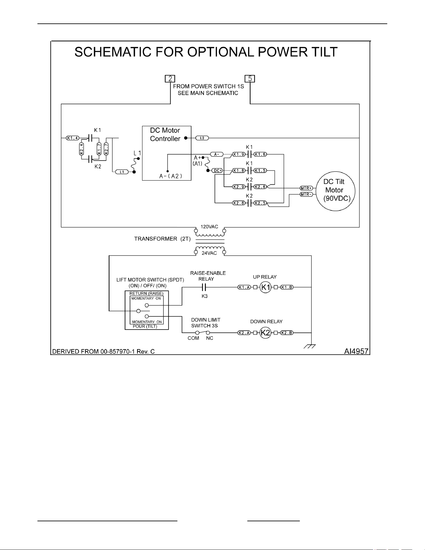
Fig. 76
K Series Gas Kettles 2/3 Jacketed Stationary and Tilting - ELECTRICAL OPERATION
Page 51 of 55 F45461 Rev. E (0124)

TROUBLESHOOTING
STATIONARY & TILTING - GENERAL
K Series Gas Kettles (Stationary & Tilting)
SYMPTOM POSSIBLE CAUSE
Kettle does not heat, power light is lit,
heat light is lit, ignition fail light is lit, low
water light is not lit, blower motor is ON
(high speed is default for blower if speed
control malfunctions).
1. Gas supply is OFF.
2. Transformer (1T) output voltage is low.
3. Tilting models only - Gas shut-off valve (1SOL) not receiving power
or malfunction.
4. Spark ignitor.
A. Spark probe dirty or corroded (poor spark).
B. Burner flame sense current too low - dirty or corroded probe or
flame sense wire connection corroded.
C. Wet insulation in burner area.
5. Ignition module malfunction (no sparking at ignitor).
6. Gas valve malfunction.
Kettle does not heat, power light is lit,
low water light is lit, heat light is not lit,
blower motor not ON.
1. Incorrect voltage to water level control (internal circuit protects board
from voltages above 132VAC or below 108VAC). Check supply
voltage to kettle. Verify polarity on incoming power supply to unit.
2. Fluid level in reservoir jacket below water level probe (LLCO). Check
fluid level in sight glass.
3. Kettle jacket was refilled incorrectly with deionized or reverse
osmosis (RO) water. Use distilled water only.
NOTE: Add approximately 1/8 teaspoon of salt to jacket fluid. Lightly
rinse fill port and close it.
4. Water level probe (LLCO) wiring connection malfunction; or probe
coated (not sensing fluid) or probe malfunction.
5. Water level control malfunction.
Kettle does not heat, power light is lit,
low water light is not lit, heat light is not
lit, blower motor not ON.
1. Tilting models only - Tilt switch (2S) is open: Kettle not fully upright
or switch not adjusted properly; or switch malfunction.
2. Pressure switch (1PAS) open or malfunction (fixed, not adjustable).
3. WLC malfunction (water level ok in sight glass).
NOTE: LLCO LED is ON (probe sensing fluid).
4. Temperature sensor malfunction; potentiometer setting too low or
malfunction; or temperature controller malfunction.
5. Interconnecting wiring malfunction.
K Series Gas Kettles 2/3 Jacketed Stationary and Tilting - TROUBLESHOOTING
F45461 Rev. E (0124) Page 52 of 55

K Series Gas Kettles (Stationary & Tilting)
SYMPTOM POSSIBLE CAUSE
Kettle does not heat, power light is not
lit.
1. Kettle unplugged; main circuit breaker off; or incoming supply line
fuse F1 open.
2. Supply voltage incorrect.
3. Ground fault receptacle (GFCI) is tripped.
4. Hood system with a power interrupt is not ON.
5. Power switch off or malfunction.
6. Interconnecting wiring malfunction.
Kettle heats up slow or will not boil
product.
1. No vacuum in reservoir jacket when kettle is cold.
2. Pressure relief valve is not seated properly (leaking) or malfunction.
See VENTING.
3. Fill port is not fully closed and leaking.
4. Jacket overfilled with fluid.
5. Gas supply line to kettle is undersized for the gas volume required.
NOTE: Increase gas line size to 125% of kettle rated BTU input.
6. Low gas supply pressure.
7. Temperature sensor malfunction; or potentiometer malfunction; or
temperature controller missing jumper on J1 or malfunction.
NOTE: Controller LED is ON when output is closed.
8. Blower does not increase to high speed.
A. Delay on make timer (1TMR) malfunction.
B. Relay K1 malfunction (N.O. contacts remain open with coil
energized - Provides high speed signal to blower speed control).
C. Blower speed control - switches not set properly or control
malfunction (no output voltage to blower: J6-1 (24VDC); J6-2
(COM); J6-4 (PWM - pulse width modulation speed signal, not
measurable with VOM).
D. Blower malfunction.
9. Gas valve not adjusted properly or malfunction.
Low water light is lit or Low water in sight
glass.
1. Tilting models only - Kettle tilted (not level).
2. Fluid level in kettle jacket is low.
3. Pressure relief valve is not seated properly (leaking) or malfunction.
See VENTING.
4. Fill port is not fully closed and leaking.
5. Kettle jacket was refilled incorrectly with deionized or reverse
osmosis (RO) water. Use distilled water only.
NOTE: Add approximately 1/8 teaspoon of salt to jacket water.
Lightly rinse fill port and close it.
K Series Gas Kettles 2/3 Jacketed Stationary and Tilting - TROUBLESHOOTING
Page 53 of 55 F45461 Rev. E (0124)
K Series Gas Kettles (Stationary & Tilting)
SYMPTOM POSSIBLE CAUSE
Kettle not heating (burner not lighting
during trial for ignition or staying lit), heat
light is lit, ignition fail light is ON, power
light is lit, blower is ON (high speed is
default for blower if speed control
malfunctions).
NOTE: If heat light is not lit but the
blower is running, the light or wiring to
the light may be malfunctioning.
1. Gas supply not on.
2. Tilting models only - Gas shut-off valve (1SOL) not receiving power
or malfunction.
3. Ignition module not receiving power.
4. Unit not properly grounded and/or polarity of incoming power is
incorrect on automatic ignition systems.
5. Low gas supply pressure.
6. Spark ignitor.
A. Spark probe dirty or corroded (poor spark).
B. Burner flame sense current too low - dirty or corroded probe; or
flame sense wire connection corroded.
7. Ignition module malfunction (no sparking at ignitor).
8. Blower speed control - switches not set properly or control
malfunction (no output voltage to blower: J6-1 (24VDC), J6-2 (COM),
J6-4 (PWM - pulse width modulation speed signal, not measurable
with VOM).
9. Blower intake clogged or blower malfunction.
10. Gas valve not adjusted properly or malfunction.
11. Burner insulation wet. Refer to BURNER.
POWER TILTING OPTION ONLY
POWER TILTING OPTION ONLY
SYMPTOM POSSIBLE CAUSES
Kettle will not raise.
1. Tilt switch (2S) open or malfunction.
2. Transformer 2T inoperative.
3. Power switch off or malfunction.
4. Tilt control switch malfunction (momentary on - raise).
5. Raise-enable relay (K3) malfunction.
6. K1 up relay malfunction.
7. DC motor controller - Fuses open or controller malfunction.
8. DC tilt motor inoperative.
9. Gear reducer malfunction.
K Series Gas Kettles 2/3 Jacketed Stationary and Tilting - TROUBLESHOOTING
F45461 Rev. E (0124) Page 54 of 55

POWER TILTING OPTION ONLY
SYMPTOM POSSIBLE CAUSES
Kettle will not tilt
1. Transformer 2T inoperative.
2. Power switch off or malfunction.
3. Tilt motor switch malfunction (momentary on - tilt).
4. Down limit switch open or malfunction.
5. K2 down relay malfunction.
6. DC tilt motor controller - Fuses open or controller malfunction.
7. DC tilt motor inoperative.
8. Gear reducer malfunction.
K Series Gas Kettles 2/3 Jacketed Stationary and Tilting - TROUBLESHOOTING
Page 55 of 55 F45461 Rev. E (0124)