INSTALLATION &
OPERATION MANUAL
For additional information on Vulcan or to locate an authorized parts
and service provider in your area, visit our website at www.vulcanequipment.com
VULCAN
DIVISION OF ITW FOOD EQUIPMENT GROUP, LLC
WWW.VULCANEQUIPMENT.COM
3600 NORTH POINT BLVD.
BALTIMORE, MD 21222
FORM 31227 Rev. C (September 2020)
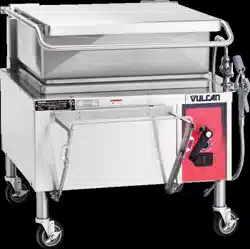
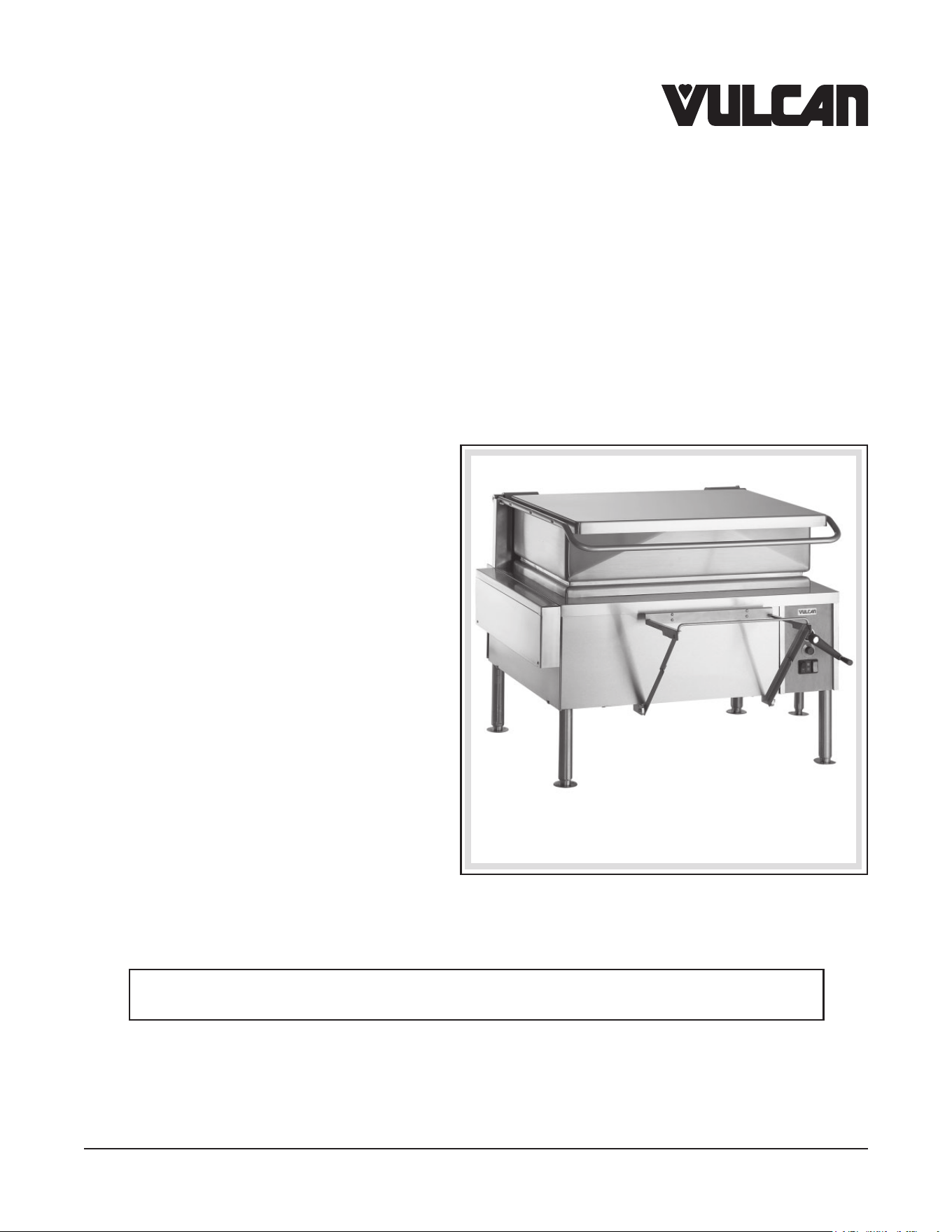
VG30, VG40, VE30 & VE40 BRAISING PANS
MODELS
VG30 ML-126847
VG40 ML-126848
VE30 ML-152047
VE40 ML-152048
Model VE40

IMPORTANT FOR YOUR SAFETY
THIS MANUAL HAS BEEN PREPARED FOR PERSONNEL QUALIFIED TO INSTALL GAS
EQUIPMENT, WHO SHOULD PERFORM THE INITIAL FIELD START-UP AND ADJUSTMENTS
OF THE EQUIPMENT COVERED BY THIS MANUAL.
POST IN A PROMINENT LOCATION THE INSTRUCTIONS TO BE FOLLOWED IN THE EVENT
THE SMELL OF GAS IS DETECTED. THIS INFORMATION CAN BE OBTAINED FROM THE
LOCAL GAS SUPPLIER.
IMPORTANT
IN THE EVENT A GAS ODOR IS DETECTED, SHUT DOWN UNITS
AT MAIN SHUTOFF VALVE AND CONTACT THE LOCAL GAS
COMPANY OR GAS SUPPLIER FOR SERVICE.
FOR YOUR SAFETY
DO NOT STORE OR USE GASOLINE OR OTHER FLAMMABLE
VAPORS OR LIQUIDS IN THE VICINITY OF THIS OR ANY OTHER
APPLIANCE.
IMPROPER INSTALLATION, ADJUSTMENT,
ALTERATION, SERVICE OR MAINTENANCE CAN CAUSE
PROPERTY DAMAGE, INJURY OR DEATH. READ THE
INSTALLATION, OPERATING AND MAINTENANCE INSTRUCTIONS
THOROUGHLY BEFORE INSTALLING OR SERVICING THIS
EQUIPMENT.
IN THE EVENT OF A POWER FAILURE, DO NOT ATTEMPT TO
OPERATE THIS DEVICE.
RETAIN THIS INSTRUCTION MANUAL FOR FUTURE REFERENCE
– 2 –
©VULCAN, 2020

– 3 –
TABLE OF CONTENTS
GENERAL .............................................................................................................................................................. 4
INSTALLATION .....................................................................................................................................................4
Unpacking ........................................................................................................................................................4
Location ...........................................................................................................................................................4
Installation Codes and Standards ....................................................................................................................6
Leveling and Anchoring the Tilting Braising Pan ..............................................................................................6
Service Connections ........................................................................................................................................6
Gas Connections .............................................................................................................................................7
Testing the Gas Supply System .......................................................................................................................7
Ventilation ........................................................................................................................................................7
Control Circuit Power Connection — Gas Braising Pans ................................................................................7
Electrical Connections .....................................................................................................................................8
Installation Diagram .........................................................................................................................................9
OPERATION .......................................................................................................................................................10
Before first use .............................................................................................................................................10
Gas Heat Braising Pans .................................................................................................................................10
Electric Heat Braising Pans ...........................................................................................................................12
Operation of the Lifting System ...................................................................................................................... 12
Unloading Prepared Foods ............................................................................................................................13
Steaming Inserts (Optional) ...........................................................................................................................14
Suggested Uses For Your Braising Pan ......................................................................................................... 14
STAINLESS STEEL EQUIPMENT CARE AND CLEANING ............................................................................15
CLEANING ..........................................................................................................................................................17
Compression Draw-O Valve Cleaning Instructions ......................................................................................18
COOKING GUIDELINES (Domestic Measurements) ........................................................................................19
COOKING GUIDELINES (Metric Measurements) ..............................................................................................22
MAINTENANCE ..................................................................................................................................................25
Lubrication .....................................................................................................................................................25
Adjustments ...................................................................................................................................................25
Flue ................................................................................................................................................................25
Service and Parts Information ........................................................................................................................ 25
TROUBLESHOOTING .......................................................................................................................................26
Gas Heat Braising Pans .................................................................................................................................26
Electric Heat Braising Pans ...........................................................................................................................26

– 4 –
INSTALLATION, OPERATION AND CARE OF
TILTING BRAISING PANS
MODELS VG30, VG40, VE30 & VE40
SAVE THESE INSTRUCTIONS FOR FUTURE USE
GENERAL
Vulcan Tilting Braising Pans are available in two sizes. Models VG30 and VE30 have a 30-gallon (114 L)
capacity, and Models VG40 and VE40 have a 40-gallon (151 L) capacity.
The tilting braising pan is a versatile piece of equipment. It allows you to stew, simmer, pan fry, braise,
grill or sauté, and all with a very uniform heat pattern.
Standard features on all models include thermostat, manual lift, drop-away food pan support and four
anged feet.
Optional features include automatic power lift and casters.
Your Vulcan braising pan is produced with quality workmanship and material. Proper installation, usage
and maintenance will result in many years of satisfactory performance.
Vulcan suggests that you thoroughly read this entire manual and carefully follow all of the instructions
provided.
INSTALLATION
Before installing, verify that the electrical service and gas supply (natural or propane) agree with the
specications on the rating plate located on the left front edge of the table top.
UNPACKING
This braising pan was carefully inspected before leaving the factory. The transportation company assumes
full responsibility for safe delivery upon acceptance of this shipment.
Immediately after unpacking, check for possible shipping damage. If the tilting braising pan is found to be
damaged, save the packaging material and contact the carrier within 5 working days of delivery.
LOCATION
For Gas-Powered Braising Pans Only
The braising pan must be kept free and clear from combustible substances. The braising pan, when
installed, must have minimum clearance from combustible construction of 2" (5 cm)
from the sides
and 6" (15 cm) from the rear. Minimum clearance from noncombustible construction is 0" from the sides
and 6" (15 cm) from the rear.
– 5 –
The installation location must allow adequate clearances for servicing and proper operation. Recommended
clearances are 24" (61 cm) on the sides and back (for servicing), and 36" (91 cm) on the front.
The braising pan must be installed so that the ow of combustion and ventilation air will not be obstructed.
Adequate clearance for air openings into the combustion chamber must be provided. Make sure there
is an adequate supply of air in the room suitable for the amount of combustion gas feeding the braising
pan burners.
Do not permit fans to blow directly at the braising pan. Wherever possible, avoid open windows next to
the braising pan. Avoid wall-type fans which create air crosscurrents within the room.
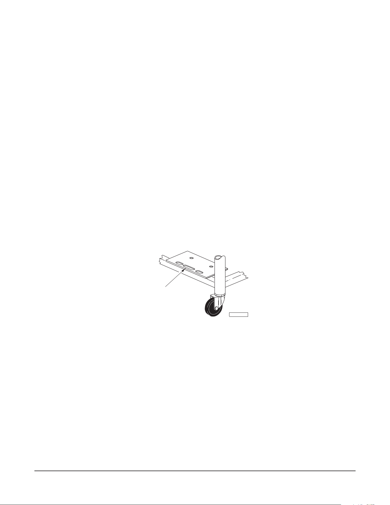
Gas-Powered Braising Pans Equipped with Casters (Optional)
If casters are assembled to the braising pan, the installation must be made using:
1. A connector (not supplied by Vulcan) that complies with the Standard for Connectors for Movable
Gas Appliances, ANSI Z21.69 (latest edition) or Connectors for Movable Gas Appliances, CAN/
CGA-6.16 (latest edition).
2. A quick-disconnect device that complies with the Standard for Quick-Disconnect Devices for
Use
With Gas Fuel, ANSI Z21.41 or Quick-Disconnect Devices for Use with Gas Fuel, CAN1-
6.9
(latest edition).
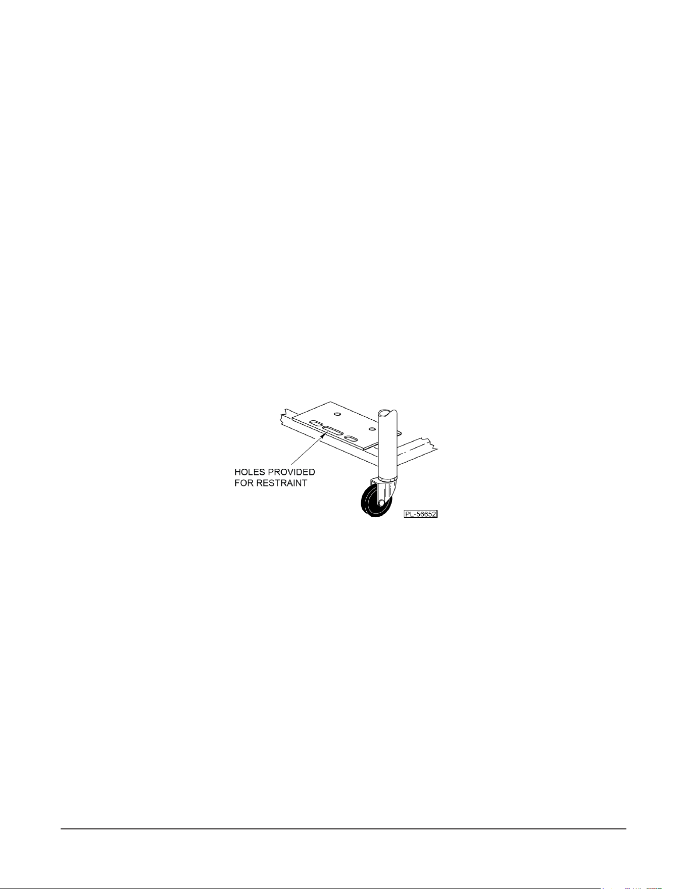
Adequate means must be provided to limit the movement of the appliance, without depending on the
connector and/or any quick-disconnect device or its associated piping to limit braising pan movement.
Attach the restraint at the rear of the braising pan (Fig. 1).
Fig. 1
If disconnection of the restraint is necessary, turn o the gas supply before disconnection. Reconnect this
restraint prior to turning the gas supply on and prior to returning the braising pan to its originally installed
position.

– 6 –
INSTALLATION CODES AND STANDARDS
Your Vulcan tilting braising pan must be installed in accordance with:
In the United States:
1. State and local codes, or in the absence of local codes, with:
2. National Fuel Gas Code ANSI-Z223.1 (latest edition), available from The American Gas Association,
Inc., 1515 Wilson Boulevard, Arlington, VA 22209.
3. National Electrical Code ANSI/NFPA-70 (latest edition).
4. ANSI NFPA Standard #96 Vapor Removal from Cooking Equipment (latest edition), available from
The National Fire Protection Association, Batterymarch Park, Quincy, MA 01169.
In Canada:
1. Local codes.
2. CAN/CGA-B149.1 National Fuel Gas Code (latest edition), available from The Canadian Gas
Association, 178 Rexdale Boulevard, Etobicoke, Ontario, Canada M9W 1R3.
3. Canadian Electrical Code Part 1 CSA-C22.1 (latest edition), available from The Canadian Standards
Association, 178 Rexdale Boulevard, Etobicoke, Ontario, Canada M9W 1R3.
LEVELING AND ANCHORING THE TILTING BRAISING PAN
1. Place the braising pan in the nal installed position.
2. Place a carpenter's level on the braising pan table top and turn the adjustable feet to level the braising
pan table top side-to-side and front-to-back. Do not attempt to level the braising pan base.
3. Mark hole locations on the oor through the anchoring holes provided in the rear, anged adjustable
feet.
4. Remove the tilting braising pan from the installation location and drill holes in the locations marked
on the oor. Insert proper anchoring devices (not supplied).
5. Place the tilting braising pan back in the installation location.
6. Place a carpenter's level on top of the braising pan, and re-level side-to-side and front-to-back.
7. Bolt and anchor the tilting braising pan securely to the oor.
8. Seal bolts and anged feet with Silicon sealant or equivalent compound.
SERVICE CONNECTIONS
To access service and utility connections, remove the left side panel. To remove, hold the panel from
underneath and lift it up. While holding the panel up, swing out the lower part of the panel until it clears
the bottom ange and remove the panel. If required, the rear panel can also be removed using the same
procedure.
The gas-powered braising pan is supplied with a 120-volt power cord.
The electrical connection for the electric braising pan can be accessed from the rear or the left panel.

– 7 –
GAS CONNECTIONS (See Fig. 2)
All gas supply connections and any pipe joint compound used must be resistant to the action of propane gases.
Connect a
3
/4" (nominal) gas supply to the braising pan. Recommended incoming gas line pressure is 7"
W.C. (Water Column) (48.3 kPa) for natural gas or 11" W.C. (75.8 kPa) for propane gas.
Make sure the pipes are clean and free of obstructions, dirt and piping compound.
Codes require that a gas shuto valve be installed in the gas line ahead of the tilting braising pan.
Natural gas and propane gas braising pans are equipped with xed orices, and no adjustment is necessary.
The manifold is set at 3.7 W.C. (Water Column) (25.5 kPa) for natural gas and 10" W.C. (68.9 kPa) for
propane gas.
Prior to lighting, check all joints in the gas supply line for leaks. Use soap and water
solution. Do not use an open ame.
After piping has been checked for leaks, all piping receiving gas should be fully purged to remove air.
The electrical control circuit must be connected (see CONTROL CIRCUIT POWER CONNECTION in this
manual).
TESTING THE GAS SUPPLY SYSTEM
When test pressures exceed
1
/2 psig (3.45 kPa), the tilting braising pan and its individual shuto valve
must be disconnected from the gas supply piping system.
When test pressures are
1
/2 psig (3.45 kPa) or less, the tilting braising pan must be isolated from the gas
supply system by closing its individual manual shuto valve.
VENTILATION
DO NOT obstruct the ow of ue gases from the ue duct located on the rear of the tilting braising pan.
It is recommended that the ue gases be ventilated to the outside of the building through a ventilation
system installed by qualied personnel.
from the termination of the braising pan ue vent to the lters of the hood venting system, an 18"
(46
cm) minimum clearance must be maintained. The ue is not to be directly connected to the ventilation
system.
Local jurisdictions may require a ventilation system to exhaust the steam from this appliance. Clearance
should be provided for the lid to be raised without interference with the hood. A ceiling that is too low may
not allow for an installation of a hood to meet this requirement.
CONTROL CIRCUIT POWER CONNECTION — GAS BRAISING PANS (See Fig. 2)
Appliances equipped with a exible electric supply cord are provided with a three-
prong grounding plug. It is imperative that this plug be connected into a properly grounded three-
prong receptacle. If the receptacle is not the proper grounding type, contact an electrician. Do
not remove the grounding prong from this plug.

– 8 –
ELECTRICAL CONNECTIONS (SEE FIG. 2)
Electrical and grounding connections must comply with the national electrical code
and/or other local codes.
Disconnect the electrical power to the machine and follow lockout / tagout procedures.
The eld connection box for eld wire connection of Models VE30 and VE40 is located at the back of the
braising pan. A knockout hole is provided for a 1" (2.5 cm) conduit connection.
1. Remove the eld connection box cover plate. Mount suitable 1" (2.5 cm) conduit tting in the conduit
opening provided on the bottom surface.
2. Connect eld wire to the terminal block as indicated on the wiring diagram. The wiring diagram is
located on the inside of the eld box lid. Wire must be of the type suitable for 75°C service and at
the suitable gauge for loads shown on the data plate.
3. After making the connections, replace the control box cover plate.
4. The braising pan must be grounded by installing a properly grounded lead to the ground lug located
inside the eld connection box.
ELECTRICAL DATA CHART
Model
Number
V (L-L)
Rated Line Current (A)
Rated
Power
(kW)
3Ø 1Ø
L1 L2 L3
VE30-FB
208 33.3 33.3 33.3 57.7 12
240 28.9 28.9 28.9 50.0 12
480 14.4 14.4 14.4 - 12
VE40-FB
208 45.9 41.6 45.9 76.9 16
240 39.7 36.1 39.7 66.7 16
480 19.9 18.0 19.9 - 16
These values are nominal ratings. Field wire connections must be capable of withstanding anticipated
surges.
– 9 –
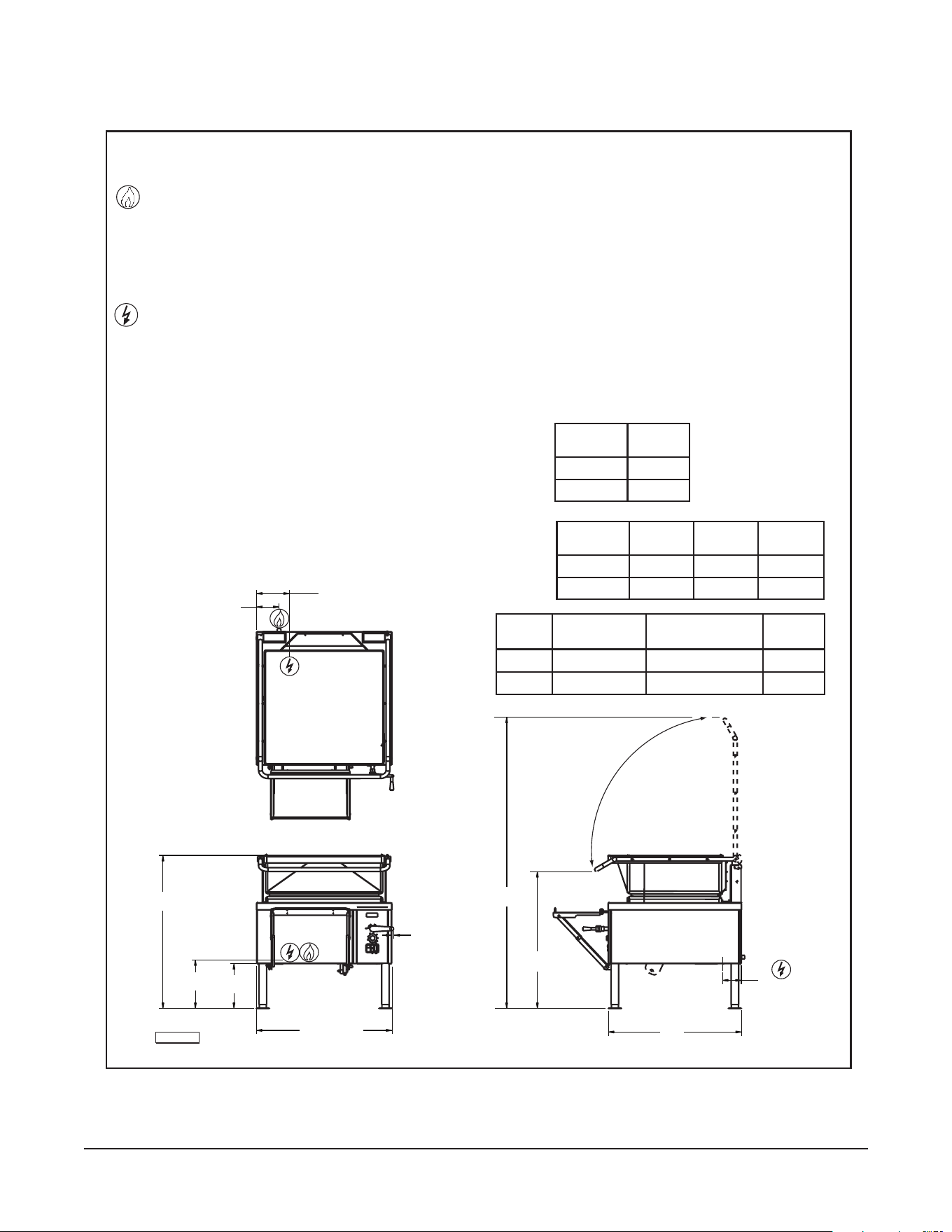
INSTALLATION DIAGRAM
Fig. 2
76"
(1930 mm)
36.761"
(934 mm)
.501"
(12.7 mm)
46"
(1168 mm)
36"
(914 mm)
40.75"
(1040 mm)
12"
(305 mm)
14"
(355 mm)
35.5"
(900 mm)
6"
(153 mm)
8.75"
(222 mm)
5"
(127 mm)
SERVICE CONNECTIONS:
ELECTRICAL: Machine is supplied with 120-VAC,
1-phase, 15-amp. power cord.
GAS INPUT: 3/4" N.P.T., Nat.6"-14" W.C.,
IMPORTANT
1. A pressure regulator sized for this unit is included. Natural gas 7"
W.C., propane gas 11" W.C. supply pressure.
propane gas 11" - 18" W.C., See capacity chart.
2. Gas line connecting to appliance must be
3
/
4
" or larger. If flexible
connectors are used, the inside diameter must be at least the same
as the
3
/
4
" iron pipe.
3. An adequate ventilation system is required for commercial cooking
equipment. Information may be obtained by writing to the National
Fire Protection Association, Batterymarch Park, Quincy, MA 02289.
When writing, refer to NFPA No. 96.
4. These units are manufactured for installation in accordance with
ANSZ223.1A (latest edition), National Fuel Gas Code. Copies may
be obtained from the American Gas Association, 1515 Wilson Blvd.,
Arlington, VA 22209.
5. Clearances: Combustible Noncombustible
Rear 6 6
Sides 2 0
6. This appliance is manufactured for commercial installation only and
is not intended for home use.
ELECTRICAL CONNECTION: 1" dia. conduit, fitting
to be installed by installer.
Cooking 4 oz.
MODEL Surface Area Capacity Portions
VE/VG30 29" x 23" 30 gal./114 liters 960
VE/VG40 39" x 23" 40 gal./152 liters 1280
BTU/hr.
MODEL Input
VG30 90,000
VG40 120,000
208
VAC
MODEL
VE30
VE40
12 KW
16 KW
12 KW
16 KW
12 WK
16 KW
240
VAC
480
VAC
PL-56638
GAS BRAISING PAN:
1.
ELECTRICAL BRAISING PAN:
2.
– 10 –
OPERATION
The tilting braising pan and its parts are hot. Use care when operating, cleaning
or servicing the braising pan.
BEFORE FIRST USE
Use a noncorrosive, grease-dissolving commercial cleaner to clean the protective metal oils from all
surface parts and the interior of the tilting braising pan. Follow the cleaner manufacturer's directions.
Rinse thoroughly and drain the pan. Wipe dry with a soft, clean cloth.
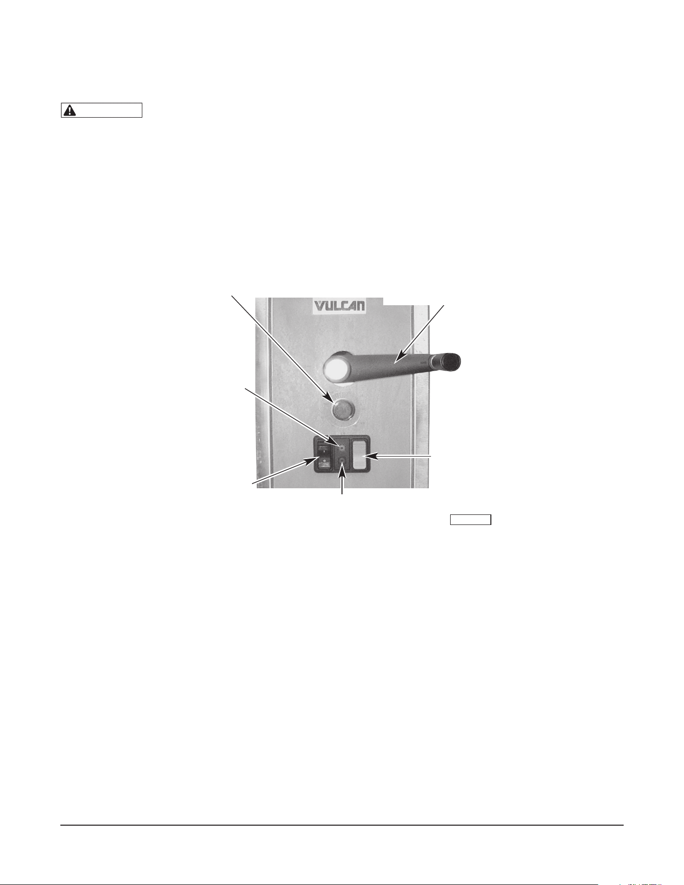
GAS HEAT BRAISING PANS
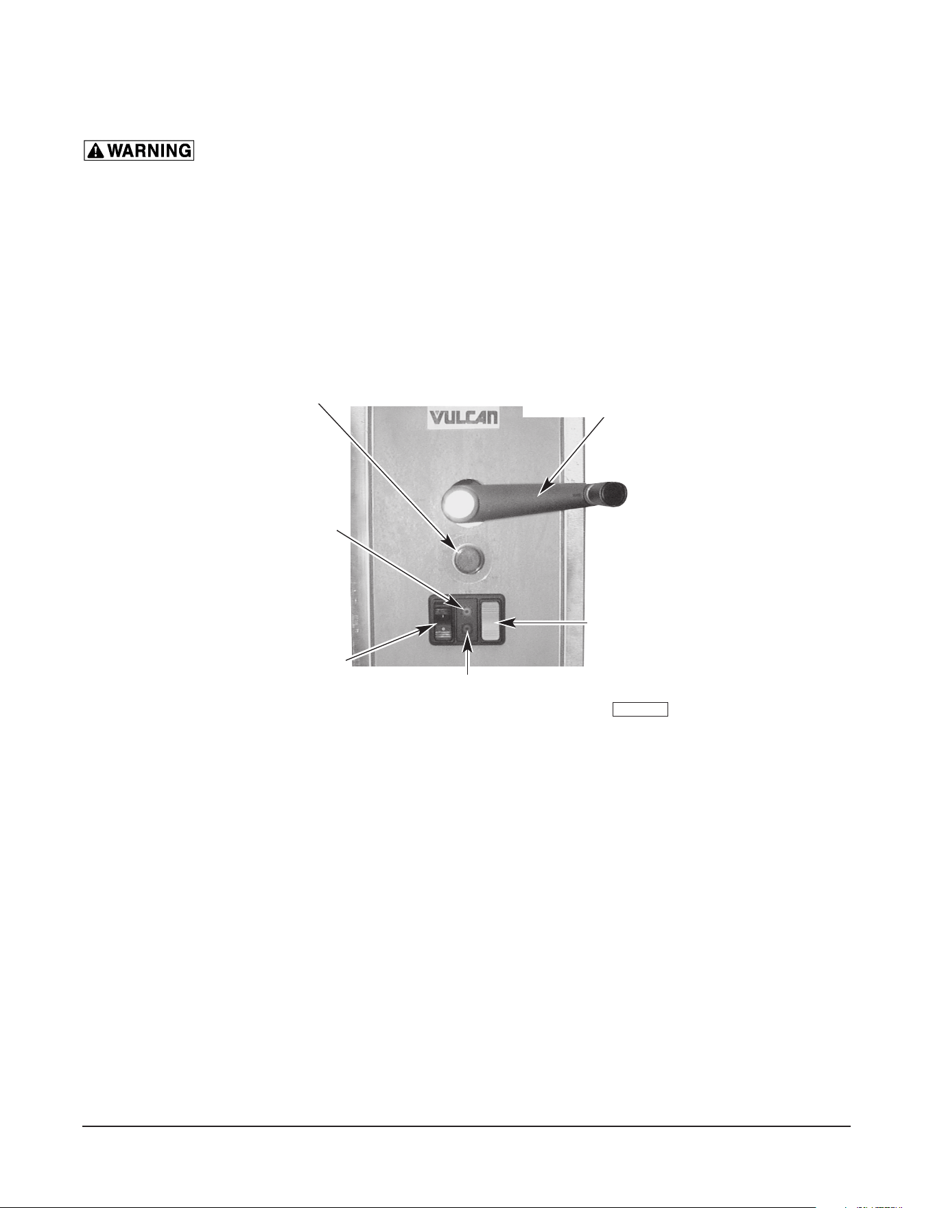
Controls (Fig. 3)
Fig. 3
Thermostat — Sets desired cooking temperature.
On/O Switch (Black) — Turns the braising pan on and o.
Amber Light — When lit, indicates the machine is turned on.
Heat Light (Red) — When lit, indicates the thermostat is calling for heat.
Auto. Power Lift (Gray) — (Optional). Push the upper part of the switch to raise the braising
pan; push the lower part to lower the braising pan. Always remove
the manual lift crank handle before operating the automatic power lift.
Manual Lift Crank Handle
— Use to manually raise and lower the braising pan.
PL-41750-1
THERMOSTAT
ON / OFF
SWITCH
[
O
] = OFF
[
I
] = ON
OPTIONAL
AUTOMATIC
POWER
LIFT
RED HEATLIGHT
AMBER
LIGHT
MANUAL LIFT CRANK
HANDLE

– 11 –
Lighting and Shutdown of Pilot
Lighting instructions are also located on the front panel.
1. Turn main gas supply to the braising pan to the ON position at the shuto valve.
2. Lower the braising pan (see OPERATION OF LIFTING SYSTEM in this manual). The braising pan
will not operate with the pan in the UP position (5 degrees or higher from horizontal).
3. Turn the black on/o switch to the ON position. The ON position is indicated by a glowing amber
light on the control panel.
4. Turn the thermostat to the desired cooking temperature.
5. If pilot is extinguished, turn the gas supply and the on/o switch to the Off position. Wait 5 minutes
before relighting.
Nightly Shutdown
Turn the on/o switch to the Off position.
Extended Shutdown
Turn the on/o switch to the Off position and turn o the gas supply.
Operating the Gas Braising Pan
The braising pan does not require any adjustments before startup.
The entire ue duct opening (located across the rear of the braising pan) must be left uncovered.
Turn the on/o switch to the ON position and turn the thermostat to the desired temperature to put the
braising pan into operation.
To prevent discoloration of the stainless steel cooking surface, do not turn the heat on unless the braising
pan is covered with a uid, a thin layer of cooking oil or food to be cooked.
DO NOT use the braising pan as a deep fat fryer; use it only for shallow pan frying (cooking oil lm not
more than
1
/8" [0.3 cm] thick). Its use for deep frying could result in a re hazard. See SUGGESTED
USES FOR YOUR BRAISING PAN in this manual for additional information.
Do not overheat the clad stainless steel plate by setting the temperature well above recommended
temperatures or by operating the braising pan without any uid inside the pan to absorb heat. Overheating
the plate may cause warping and will carbonize any cooking oil on the plate and cause sticking.
In case of a power failure, there will be no ames because the combination control valve will shut o the
gas ow. In the event of a power failure, immediately turn the on/o switch to the Off position. Once
power is restored, turn the on/o switch to the ON position to resume cooking.
The lid is spring-loaded and will stay in any position at which it is placed. After some time, the springs
may need to be tightened. Call your local Vulcan-authorized servicer to make these adjustments.

– 12 –
ELECTRIC HEAT BRAISING PANS
Controls (see Fig. 3)
Thermostat — Sets desired cooking temperature.
On/O Switch (Black) — Turns the braising pan on and o.
Amber Light — When lit, indicates the machine is turned on.
Heat Light (Red) — When lit, indicates the thermostat is calling for heat.
Auto. Power Lift (Gray) — (Optional). Push the upper part of the switch to raise the braising pan;
push the lower part to lower the braising pan. Always remove the manual
lift crank handle before operating the automatic power lift.
Manual Lift Crank Handle
— Use to manually raise and lower the braising pan.
Operating the Electric Braising Pan
The braising pans do not require any adjustments before startup.
Turn the black on/o switch to the ON position.
Lower the braising pan (see OPERATION OF LIFTING SYSTEM in this manual). The braising pan will
not operate with the pan in the UP position (5 degrees or higher from horizontal).
Turn the thermostat to the desired cooking temperature.
To prevent discoloration of the stainless steel cooking surface, do not turn the heat on unless the braising
pan surface is covered with a uid, a thin layer of cooking oil or food to be cooked.
DO NOT use the braising pan as a deep fat fryer; use it only for shallow pan frying (cooking oil lm not
more than
1
/8" [0.3 cm] thick). Its use for deep frying could result in a re hazard. See SUGGESTED
USES FOR YOUR BRAISING PAN in this manual for additional information.
Do not overheat the clad stainless steel plate by setting the temperature well above recommended
temperatures or by operating the braising pan without any uid inside the pan to absorb heat. Overheating
the plate may cause warping and will carbonize any cooking oil on the plate and cause sticking.
The lid is spring-loaded and will stay in any position at which it is placed. After some time, the springs
may need to be tightened. Call your local Vulcan-authorized servicer to make these adjustments.
OPERATION OF THE LIFTING SYSTEM
Keep the area underneath and around the braising pan clear of your hands or any other objects when
operating the lifting system.
Do not obstruct any of the moving parts of the lift system located underneath the table top on the right and/
or left side of the braising pan. This area must be kept clear of any objects or obstructions at all times.
Do not leave the braising pan in the UP position for extended periods (e.g., overnight or during a shutdown
period between cooking times).

– 13 –
Fig. 4
Braising Pans with Manual Lift (Standard)
1. The crank for the manual lift system is shipped separately.
2. There are two pins on one end of the crank. Insert the crank through the hole on the control panel
so that the two pins engage in the slots of the speed reducer coupling located behind the panel.
3. Turn the crank handle clockwise to lift the braising pan and counterclockwise to lower the braising
pan.
4. This lift system is not aected by a power failure and can be operated during a power failure.
5. Refer to the MAINTENANCE section of this manual for lubrication and maintenance instructions.
Braising Pans with Automatic Power Lift (Optional)
1. The automatic lift cannot raise the braising pan unless the lid is fully opened.
2. The pan lift is controlled by the gray rocker switch located on the control panel (see Fig. 3).
3. Always remove the manual crank handle before operating the automatic power lift.
4. Press the upper half of the gray rocker switch to raise the braising pan and the lower half of the gray
rocker switch to lower the braising pan. The switch must be held for continuous raising or lowering
of the braising pan.
5. In case of a power failure, use the hand crank (shipped separately) to lower or raise the pan (same
as the braising pans with manual lift).
UNLOADING PREPARED FOODS
All braising pans are provided with a frame support (Fig. 4) for holding a food receiving pan when unloading
prepared foods.
Pull the frame support out and up until it locks. The support will accept food receiving pans of 12" x 20"
(30 cm x 50 cm) up to 6" (15 cm) deep.
When lowering the frame support, push in on the hinges until they bend, then lower the support.
PL-41751-1
HINGE
FRAME
SUPPORT
– 14 –
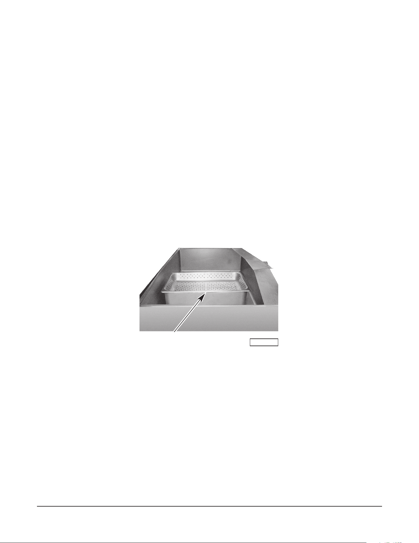
STEAMING INSERTS (Optional)
Your tilting braising pan can be used for steaming frozen and fresh foods. The 30-gallon (114 L) pans
(Models VE30 or VG30) can be loaded with a maximum of two 12" x 20" x 4"
(30 cm x 50.8 cm x
10 cm) deep steaming pans. The 40-gallon (151 L) pan (Models VE40 or VG40) will accept up to three
steam pans of this same size.
To use the braising pan for steaming, ll the pan with 6 to 7 gallons (23 to 26 L) of water (approximately
2" [5 cm] deep) for 30-gallon (114 L) models and 8 to 9 gallons (30 to 34 L) of water (approximately 2"
[5 cm] deep) for 40-gallon (151 L) models.
Turn the braising pan ON. Set the thermostat at 212°f (100°C). Allow the water to come to a boil. Then
change the thermostat setting to 250°f (121°C) and carefully place the steaming inserts into the pan as
shown in Fig. 5. Place the pan with product into the steaming insert. Close the lid and allow steaming
for the desired time.
Periodically inspect the water level inside the braising pan. Add water if the water level is less than
1
/2"
(1 cm) deep.
To use the braising pan as a food warmer or bain marie, follow the same procedure as for steaming, but
increase the depth of the water to allow the bottom and part of the sides of the steaming inserts to be
immersed in water. Set the thermostat for the holding or warming temperature desired.
The steaming inserts can be ordered from your dealer.
Fig. 5
SUGGESTED USES FOR YOUR BRAISING PAN
DO NOT use the braising pan for deep fat frying. Restrict frying activity to shallow pan frying (oil lm not
more than
1
/8" [0.3 cm] thick) or sautéing.
A tilting braising pan is quite versatile. It can be used for roasting, simmering, boiling, sautéing, searing,
frying, warming, holding, proong, thawing, browning, steaming, braising, griddling or stewing. It can
be used as an oversized skillet, as a bain marie, as a proong oven, as a stock pot, as a kettle or as an
even-heat range top. It can be used for cooking breakfasts, lunches and dinners.
Your Vulcan tilting braising pan is a multi-purpose unit that can be used for virtually any type of cooking,
except deep fat frying, with great speed, in large volume and with considerable savings in labor and energy.
PL-41752-1
STEAMING INSERT

– 15 –
STAINLESS STEEL EQUIPMENT CARE AND CLEANING
(Supplied courtesy of NAFEM. For more information, visit their web site at www.nafem.org)
Contrary to popular belief, stainless steels ARE susceptible to rusting.
Corrosion on metals is everywhere. It is recognized quickly on iron and steel as unsightly yellow/orange
rust. Such metals are called “active” because they actively corrode in a natural environment when their
atoms combine with oxygen to form rust.
Stainless steels are passive metals because they contain other metals, like chromium, nickel and manganese
that stabilize the atoms. 400 series stainless steels are called ferritic, contain chromium, and are magnetic;
300 series stainless steels are called austenitic, contain chromium and nickel; and 200 series stainless,
also austenitic, contains manganese, nitrogen and carbon. Austenitic types of stainless are not magnetic,
and generally provide greater resistance to corrosion than ferritic types.
With 12-30 percent chromium, an invisible passive lm covers the steel’s surface acting as a shield against
corrosion. As long as the lm is intact and not broken or contaminated, the metal is passive and stain-
less. If the passive lm of stainless steel has been broken, equipment starts to corrode. At its end, it rusts.
Enemies of Stainless Steel
There are three basic things which can break down stainless steel’s passivity layer and allow corrosion
to occur.
1. Mechanical abrasion
2. Deposits and water
3. Chlorides
Mechanical abrasion means those things that will scratch a steel surface. Steel pads, wire brushes and
scrapers are prime examples.
Water comes out of the faucet in varying degrees of hardness. Depending on what part of the country
you live in, you may have hard or soft water. Hard water will leave spots, and when heated leave deposits
behind that if left to sit, will break down the passive layer and rust stainless steel. Other deposits from
food preparation and service must be properly removed.
Chlorides are found nearly everywhere. They are in water, food and table salt. One of the worst chloride
perpetrators can come from household and industrial cleaners.
So what does all this mean? Don’t Despair!
Here are a few steps that can help prevent stainless steel rust.
1. Use the proper tools.
When cleaning stainless steel products, use non-abrasive tools. Soft cloths and plastic scouring pads
will not harm steel’s passive layer. Stainless steel pads also can be used but the scrubbing motion
must be in the direction of the manufacturers’ polishing marks.
2. Clean with the polish lines.
Some stainless steel comes with visible polishing lines or “grain.” When visible lines are present,
always scrub in a motion parallel to the lines. When the grain cannot be seen, play it safe and use
a soft cloth or plastic scouring pad.
3. Use alkaline, alkaline chlorinated or non-chloride containing cleaners.
While many traditional cleaners are loaded with chlorides, the industry is providing an ever-increasing
choice of non-chloride cleaners. If you are not sure of chloride content in the cleaner used, contact
your cleaner supplier. If your present cleaner contains chlorides, ask your supplier if they have an
alternative. Avoid cleaners containing quaternary salts; it also can attack stainless steel and cause
pitting and rusting.

– 16 –
4. Treat your water.
Though this is not always practical, softening hard water can do much to reduce deposits. There are
certain lters that can be installed to remove distasteful and corrosive elements. To insure proper
water treatment, call a treatment specialist.
5. Keep your food equipment clean.
Use alkaline, alkaline chlorinated or non-chloride cleaners at recommended strength. Clean frequently
to avoid build-up of hard, stubborn stains. If you boil water in stainless steel equipment, remember
the single most likely cause of damage is chlorides in the water. Heating cleaners that contain
chlorides have a similar eect.
6. Rinse, rinse, rinse.
If chlorinated cleaners are used, rinse and wipe equipment and supplies dry immediately. The sooner
you wipe o standing water, especially when it contains cleaning agents, the better. After wiping
equipment down, allow it to air dry; oxygen helps maintain the stainless steel’s passivity lm.
7. Never use hydrochloric acid (muriatic acid) on stainless steel.
8. Regularly restore/passivate stainless steel.
Job Cleaning Agent Comments
Routine cleaning Soap, ammonia,
detergent, Medallion
Apply with soft cloth or sponge.
Fingerprints and smears Arcal 20, Lac-O-Nu Ecoshine Provides barrier lm
Stubborn stains and
discoloration
Cameo, Talc, Zud,
First Impression
Rub in direction of polish lines.
Grease and fatty acids,
blood, burnt-on foods
Easy-o, DeGrease It Oven Aid Excellent removal
on all nishes
Grease and Oil Any good commercial
detergent
Apply with soft cloth or sponge.
Restoration/Passivation Benet, Super
Sheen, Wichinox
Review
1. Stainless steels rust when passivity (lm-shield) breaks down as a result of scrapes, scratches,
deposits and chlorides.
2. Stainless steel rust starts with pits and cracks.
3. Use the proper tools. Do not use steel pads, wire brushes or scrapers to clean stainless steel.
4. Use non-chlorinated cleaners at recommended concentrations. Use only chloridefree cleaners.
5. Soften your water. Use lters and softeners whenever possible.
6. Wipe o cleaning agent(s) and standing water as soon as possible. Prolonged contact causes
eventual problems.
To learn more about chloride-stress corrosion and how to prevent it, contact the equipment manufacturer
or cleaning materials supplier.
Developed by Packer Engineering, Naperville, Ill., an independent testing laboratory.
– 17 –
CLEANING
Disconect the electrical power to the machine and follow lockout / tagout procedures
before cleaning.
Clean your braising pan regularly. Keep the plate surface clean. To produce evenly cooked, perfectly braised
products, keep the pan surface free from carbonized grease. Carbonized grease on the surface hinders
the transfer of heat from the pan surface to the food. This results in spotty browning and loss of cooking
eciency. Worst of all, carbonized grease tends to cling to the foods, giving them a highly unsatisfactory
and unappetizing appearance.
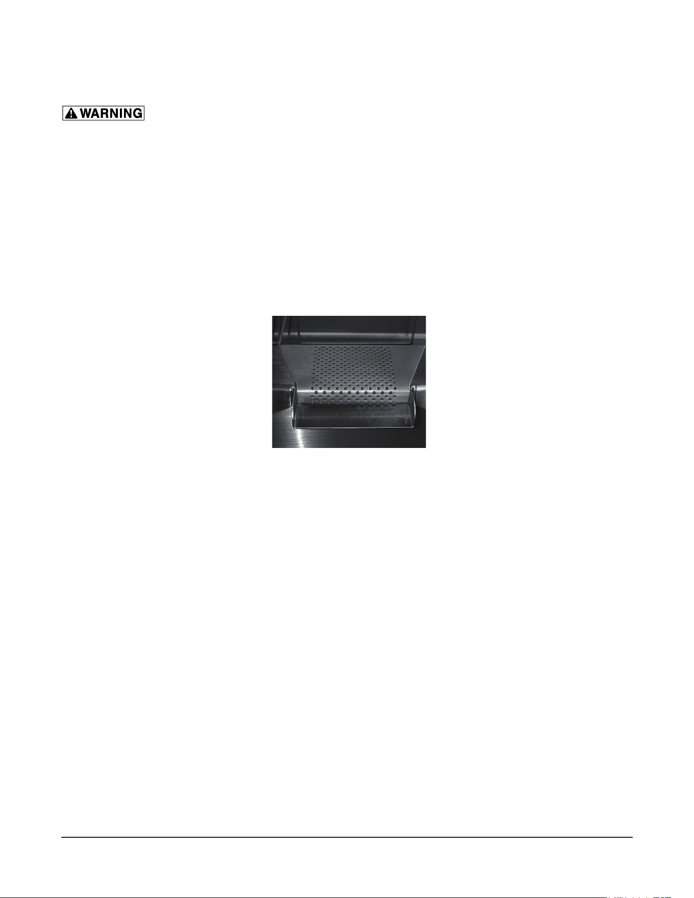
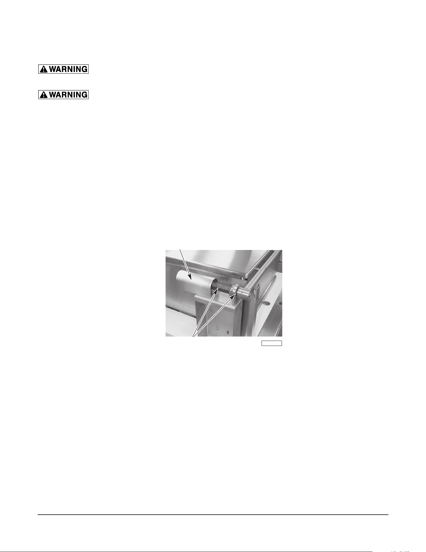
After Each Use
Clean the pan surface with a brush or exible spatula.
Remove the strainer (Fig. 6) at the pouring lip of the braising pan by pulling it toward the back of the pan.
Clean the strainer in a sink. Rinse thoroughly and dry with a soft, clean cloth. Replace strainer (Fig 6).
Once A Day:
Thoroughly clean the back, sides and front of the pan. Also clean the inside and outside surfaces of the lid.
Once A Week:
Clean the pan surface thoroughly. If necessary, use a griddle stone or brush on the surface. A detergent
may be used on the pan surface to help clean it, but be sure the detergent is thoroughly removed.
Clean other stainless steel surfaces with a damp cloth and polish with a soft, dry cloth. To remove
discolorations, use a nonabrasive cleaner. If the braising pan usage is very high, consider going through
the weekly cleaning procedures more often than once a week.
When cleaning the braising pan, it is helpful to ll the pan with approximately 10 gallons (38 L) of warm
water and add detergent. After cleaning, raise the braising pan to drain all water (place a bucket or container
under the pouring lip). Then repeat the procedures for rinsing with clean water.
Fig. 6
– 18 –
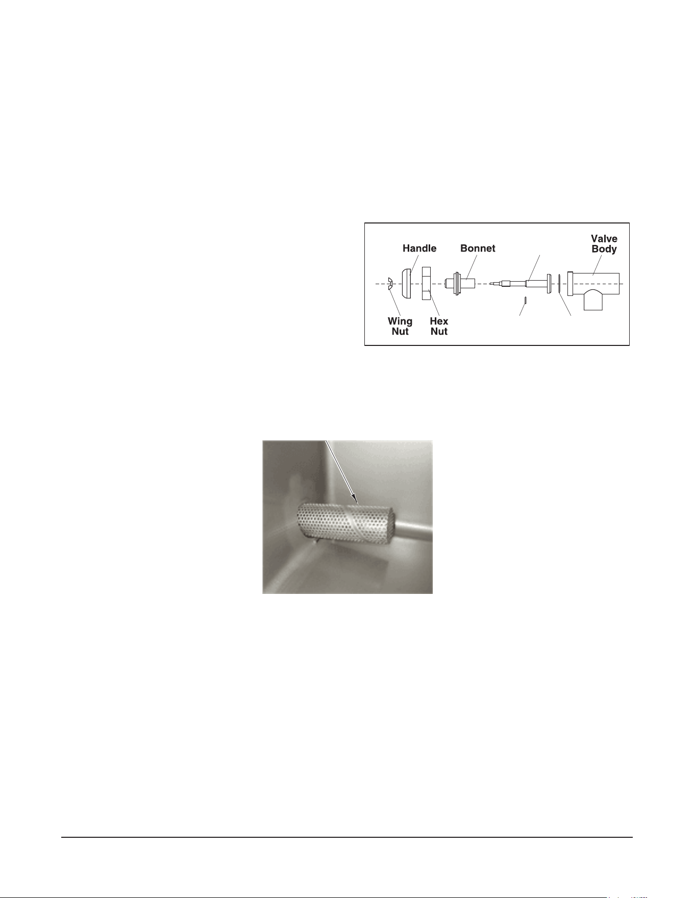
COMPRESSION DRAW-OFF VALVE CLEANING INSTRUCTIONS
Daily After Use
Remove draw-o valve stem assembly for cleaning (fig. 7).
1. Turn the valve handle counterclockwise until it stops.
2. Pull the valve handle back until it stops.
3. Turn large hex nut counterclockwise until the valve stem assembly is loose.
4. Pull the assembly straight out of the valve body.
5. Remove wing nut and handle. Unscrew valve stem from bonnet.
6. Wash valve body and stem assembly with mild soap and water, and then rinse. Make sure all
food residue is removed from inside valve body.
7. Leave assembly apart to air dry.
Install draw-o valve assembly:
1. Apply Petrol-Gel lubricant to valve stem
threads, O-Ring, rubber plug face and large
hex nut threads.
2. Thread the valve stem into bonnet till valve
stem can be pulled through bonnet.
3. Insert valve stem into valve body.
4. Install large hex nut hand tight.
5. Install valve handle, lock washer and wing nut onto the valve stem.
6. Turn valve handle clockwise until closed. Do not overtighten.
Valve Stem
Stem
O-Ring
Valve Stem
O-Ring
PROPER STRAINER INSTALLATION
FOR DRAW-OFF VALVE
Fig. 7
Fig. 8

– 19 –
COOKING GUIDELINES (Domestic Measurements)
The guidelines given below are suggested quantities, temperature settings and estimated numbers of
orders per load and per hour. When two temperatures are given, the rst is to start the product and the
second is to nish the product.
The following temperatures should be used:
Temperature
(°F)
Simmering 200 Max.
Sautéing 225 to 275
Searing 300 to 350
Frying 325 to 375
Grilling 350 to 425
ITEM
PORTION
SIZE
TEMP.
(°F)
BATCHES
PER
HOUR
VG30/VE30
PER LOAD
VG40/VE40
PER LOAD
QTY. PORTIONS QTY. PORTIONS
BREAKFAST FOODS
Bacon 3 Slices 350 12 2 lb. 10 3 lb. 15
Eggs
–Boiled-Hard 1 egg 225 5 50 eggs 50 75 eggs 75
–Boiled-Soft 1 egg 225 8 50 eggs 50 75 eggs 75
–Fried 1 egg 400 4 30 eggs 30 45 eggs 45
–Poached 1 egg 225 5 36 eggs 36 60 eggs 60
–Scrambled 1
1
/2 eggs 300 – 200 1 18 gal. 720 28 gal. 1100
French Toast 3 slices 425 7 35 slices 12 50 slices 17
Regular Oatmeal
1
/2 cup 250 2
20 lb (100 cups)
500 40 lb (200 cups) 1000
Pancakes 2 each 400 10 30 ea. 15 50 ea. 25
FISH
Clams 1 pt. 400 10 10 qts. 20 15 qts. 30
Fish Cakes 2 to 3 oz. 400 5 70 – 3 oz. 35 110 – 3 oz. 55
Haddock Fillet 4 oz. 400 4 60 – 4 oz. 60 90 – 4 oz. 90
Halibut Steak 5 oz. 425 3 60 – 4 oz. 60 90 – 4 oz. 90
Lobster 1 – 1 lb. 350 4 20 – 1 lb. 20 30 – 1 lb. 30
Swordsh 5 oz. 425 3 50 – 5 oz. 50 75 – 5 oz. 75
SAUCES, GRAVIES, SOUPS
Brown Gravy 1 oz. 350 – 200 2 30 gal. 3840 40 gal. 5120
Cream Sauce 2 oz. 250 – 175 1 30 gal. 1920 40 gal. 2560
Cream Soup 6 oz. 200 1 30 gal. 640 40 gal. 853
French Onion Soup 6 oz. 225 1 30 gal. 640 40 gal. 853
Meat Sauce 4 oz. 350 – 200 1 30 gal. 960 40 gal. 1280

– 20 –
ITEM
PORTION
SIZE
TEMP.
(°F)
BATCHES
PER
HOUR
VG30/VE30
PER LOAD
VG40/VE40
PER LOAD
QTY. PORTIONS QTY. PORTIONS
VEGETABLES
CANNED 3 oz. 400 6 30 lb. 125 45 lb. 200
FRESH
Beans, Wax, Green 3 oz. 400 3 25 lb. 125 50 lb. 250
Beets 3 oz. 400 1 30 lb. 125 60 lb. 300
Broccoli 3 oz. 400 3 25 lb. 125 40 lb. 200
Cabbage 3 oz. 400 5 20 lb. 80 30 lb. 125
Carrots 3 oz. 400 2 35 lb. 150 70 lb. 300
Cauliower 3 oz. 250 5 15 lb. 75 25 lb. 125
Corn 1 Ear 400 8 50 ears 50 75 ears 75
Potatoes 3 oz. 400 2 40 lb. 200 60 lb. 300
Spinach 4 oz. 250 10 6 lb. 25 9 lb. 35
Turnips 4 oz. 400 2 20 lb. 100 30 lb. 150
FROZEN
Beans, French Green 3 oz. 400 6 15 lb. 60 22
1
/2 lb. 90
Lima Beans 3 oz. 250 4 15 lb. 60 22
1
/2 lb. 90
Broccoli 3 oz. 400 8 12 lb. 50 18 lb. 75
Sliced Carrots 3 oz. 250 6 15 lb. 60 22
1
/2 lb. 90
Small Whole Carrots 3 oz. 250 3 15 lb. 50 22
1
/2 lb. 90
Corn 3 oz. 250 18 15 lb. 50 22
1
/2 lb. 90
Small Whole Onions 3 oz. 250 7 15 lb. 50 22
1
/2 lb. 90
Peas 3 oz. 400 10 15 lb. 75 22
1
/2 lb. 110
Spinach 3 oz. 400 3 15 lb. 75 22
1
/2 lb. 110
DESSERTS, PUDDINGS, SWEET SAUCES
Butterscotch Sauce 1 oz. 200 1 30 gal. 3840 40 gal. 5120
Cherry Cobbler 3 oz. 200 1 30 gal. 1280 40 gal. 1707
Chocolate Sauce 1 oz. 200 1 30 gal. 3840 40 gal. 5120
Cornstarch Pudding 4 oz. 200 1 30 gal. 960 40 gal. 1280
Fruit Gelatin 3 oz. 250 2 30 gal. 1280 40 gal. 1707
MEAT – POULTRY
Bacon 3 Slices 350 12 2 lb. 10 3 lb. 15
BEEF
Amer. Chop Suey 6 oz. 400 – 225 2 30 gal. 640 40 gal. 853
Beef Stew 8 oz. 300 — 30 gal. 480 40 gal. 640
Corned Beef Hash 5 oz. 400 5 20 lb. 60 30 lb. 90
Cheeseburger 3 oz. 300 12 7 lb. 35 10 lb. 50
Hamburger 3 oz. 300 15 7 lb. 35 10 lb. 50
Meatballs 1 oz. 400 – 225 3 12
1
/2 lb. 65 18 lb. 100
Pot Roast 2 oz. 350 – 200 120 lb. 500 180 lb. 750
Salisbury Steak 5 oz. 400 3 16 lb. 50 24 lb. 75
Sirloin Steak 6 oz. 400 5 15 lb. 40 22
1
/2 lb. 60
Swiss Steak 4 oz. 300 – 200 1 25 lb. 110 40 lb. 160

– 21 –
ITEM
PORTION
SIZE
TEMP.
(°F)
BATCHES
PER
HOUR
VG30/VE30
PER LOAD
VG40/VE40
PER LOAD
QTY. PORTIONS QTY. PORTIONS
CHICKEN
Pan Fried 2 –
1
/4's 350 3 50 pieces 25 80 pieces 40
Whole 2 oz. 350 – 200 16 – 5 lb. 200 24 – 5 lb. 265
FRANKFURTERS
Grilled 2 oz. 300 8 22 lb. 176 33 lb. 264
Boiled 2 oz. 250 12 16 lb. 128 25 lb. 200
PORK
Ham Steak 3 oz. 400 8 10 lb. 50 15 lb. 75
Pork Chops 5 oz. 350 4 15 lb. 50 25 lb. 75
Sausage Links 3 links 350 7 30 lb. 120 45 lb. 180
TURKEY
O Carcass 2 oz. 400 – 200 — 3–26 to 30 lb. 200 4–26 to 30 lb. 275
On Carcass 2 oz. 400 – 200 — 4–16 to 20 lb. 175 6–16 to 20 lb. 265
MISCELLANEOUS
Grilled Cheese Sandwich 1 sand. 400 8 40 sand. 40 50 sand. 50
Macaroni & Cheese 8 oz. 200 2 30 gal. 480 40 gal. 640
Rice 4 oz. 350 – 225 1 20 lb. raw 320 40 lb. raw 650
Spaghetti 4 oz. 350 – 225 2 8 lb. raw 200 12 lb. raw 300

– 22 –
COOKING GUIDELINES (Metric Measurements)
The guidelines given below are suggested quantities, temperature settings and estimated numbers of
orders per load and per hour. When two temperatures are given, the rst is to start the product and the
second is to nish the product.
The following temperatures should be used:
Temperature (°C)
Simmering 93.3 Max.
Sautéing 107 to 135
Searing 149 to 177
Frying 163 to 191
Grilling 177 to 218
ITEM
PORTION
SIZE
TEMP.
(°C)
BATCHES
PER
HOUR
VG30/VE30
PER LOAD
VG40/VE40
PER LOAD
QTY. PORTIONS QTY. PORTIONS
BREAKFAST FOODS
Bacon 3 Slices 177 12 0.9 kg 10 1.4 kg 15
Eggs
–Boiled-Hard 1 egg 107 5 50 eggs 50 75 eggs 75
–Boiled-Soft 1 egg 107 8 50 eggs 50 75 eggs 75
–Fried 1 egg 204 4 30 eggs 30 45 eggs 45
–Poached 1 egg 107 5 36 eggs 36 60 eggs 60
–Scrambled 1
1
/2 eggs 149 – 93 1 68 L 720 106 L 1100
French Toast 3 slices 218 7 35 slices 12 50 slices 17
Regular Oatmeal 118 mL 121 2 9 kg 500 18 kg 1000
Pancakes 2 each 204 10 30 ea. 15 50 ea. 25
FISH
Clams 473 mL 204 10 9 L 20 14 L 30
Fish Cakes 57 to 85 g 204 5 70 – 85 g 35 110 – 85 g 55
Haddock Fillet 113 g 204 4 60 – 113 g 60 90 – 113 g 90
Halibut Steak 142 g 218 3 60 – 113 g 60 90 – 113 g 90
Lobster 1 – 0.5 kg 177 4 20 – 0.5 kg 20 30 – 0.5 kg 30
Swordsh 142 g 218 3 50 – 142 g. 50 75 – 142 g 75
SAUCES, GRAVIES, SOUPS
Brown Gravy 28 g 177 – 93 2 114 L 3840 151 L 5120
Cream Sauce 57 g 121 – 79 1 114 L 1920 151 L 2560
Cream Soup 170 g 93 1 114 L 640 151 L 853
French Onion Soup 170 g 107 1 114 L 640 151 L 853
Meat Sauce 113 g 177 – 93 1 114 L 960 151 L 1280

– 23 –
ITEM
PORTION
SIZE
TEMP.
(°C)
BATCHES
PER
HOUR
VG30/VE30
PER LOAD
VG40/VE40
PER LOAD
QTY. PORTIONS QTY. PORTIONS
VEGETABLES
CANNED 85 g 204 6 14 kg 125 20 kg 200
FRESH
Beans, Wax, Green 85 g 204 3 11 kg 125 23 kg 250
Beets 85 g 204 1 14 kg 125 27 kg 300
Broccoli 85 g 204 3 11 kg 125 18 kg 200
Cabbage 85 g 204 5 9 kg 80 14 kg 125
Carrots 85 g 204 2 16 kg 150 32 kg 300
Cauliower 85 g 121 5 7 kg 75 11 kg 125
Corn 1 Ear 204 8 50 ears 50 75 ears 75
Potatoes 85 g 204 2 18 kg 200 27 kg 300
Spinach 113 g 121 10 3 kg 25 4 kg 35
Turnips 113 g 204 2 9 kg 100 14 kg 150
FROZEN
Beans, French Green 85 g 204 6 7 kg 60 10 kg 90
Lima Beans 85 g 121 4 7 kg 60 10 kg 90
Broccoli 85 g 204 8 5 kg 50 8 kg 75
Sliced Carrots 85 g 121 6 7 kg 60 10 kg 90
Small Whole Carrots 85 g 121 3 7 kg 50 10 kg 90
Corn 85 g 121 18 7 kg 50 10 kg 90
Small Whole Onions 85 g 121 7 7 kg 50 10 kg 90
Peas 85 g 204 10 7 kg 75 10 kg 110
Spinach 85 g 204 3 7 kg 75 10 kg 110
DESSERTS, PUDDINGS, SWEET SAUCES
Butterscotch Sauce 28 g 93 1 114 L 3840 151 L 5120
Cherry Cobbler 85 g 93 1 114 L 1280 151 L 1707
Chocolate Sauce 28 g 93 1 114 L 3840 151 L 5120
Cornstarch Pudding 113 g 93 1 114 L 960 151 L 1280
Fruit Gelatin 85 g 121 2 114 L 1280 151 L 1707
MEAT – POULTRY
Bacon 3 Slices 177 12 0.9 kg 10 1 kg 15
BEEF
Amer. Chop Suey 170 g 204 – 107 2 114 L 640 151 L 853
Beef Stew 0.2 kg 149 — 114 L 480 151 L 640
Corned Beef Hash 142 g 204 5 9 kg 60 14 kg 90
Cheeseburger 85 g 149 12 3 kg 35 5 kg 50
Hamburger 85 g 149 15 3 kg 35 5 kg 50
Meatballs 28 g 204 – 107 3 6 kg 65 8 kg 100
Pot Roast 57 g 177 – 93 54 kg 500 82 kg 750
Salisbury Steak 142 g 204 3 7 kg 50 11 kg 75
Sirloin Steak 170 g 204 5 7 kg 40 10 kg 60
Swiss Steak 113 g 149 – 93 1 11 kg 110 18 kg 160

– 24 –
ITEM
PORTION
SIZE
TEMP.
(°C)
BATCHES
PER
HOUR
VG30/VE30
PER LOAD
VG40/VE40
PER LOAD
QTY. PORTIONS QTY. PORTIONS
CHICKEN
Pan Fried 2 –
1
/4's 177 3 50 pieces 25 80 pieces 40
Whole 57 g 177 – 93 16 – 2 kg 200 24 – 2 kg 265
FRANKFURTERS
Grilled 57 g 149 8 10 kg 176 15 kg 264
Boiled 57 g 121 12 7 kg 128 11 kg 200
PORK
Ham Steak 85 g 204 8 5 kg 50 7 kg 75
Pork Chops 142 g 177 4 7 kg 50 11 kg 75
Sausage Links 3 links 177 7 14 kg 120 10 kg 180
TURKEY
O Carcass 57 g 204 – 93 — 3 –
12 to 14 kg
200 4 – 12 to 14 kg 275
On Carcass 57 g 204 – 93 — 4 – 7 to 9 kg 175 6 – 7 to 9 kg 265
MISCELLANEOUS
Grilled Cheese Sandwich 1 sand. 204 8 40 sand. 40 50 sand. 50
Macaroni & Cheese 0.2 kg 93 2 114 L 480 151 L 640
Rice 113 g 177 – 107 1 9 kg raw 320 18 kg raw 650
Spaghetti 113 g 177 – 107 2 4 kg raw 200 5 kg raw 300
– 25 –
MAINTENANCE
The tilting braising pan and its parts are hot. Use care when operating, cleaning
or servicing the braising pan.
Disconnect the electrical power to the machine and follow lockout / tagout procedures
before performing any maintenance.
LUBRICATION
Lid Mechanism
1. The lid lift mechanism and tension spring are located behind the backsplash (sheet metal panel
behind the braising pan) on both the left and right rear corners of the braising pan.
2. Take the cover o by prying and lifting up (fig. 9).
3. For smooth operation of the lid, lubricate these mechanisms with 8 to 10 drops of lubricating machine
oil every 6 months. Place a few drops of oil between the lid arm and stationary block, and a few
drops on the shaft around which the spring is coiled.
4. Replace the cover to maintain smooth operation.
Fig. 9
ADJUSTMENTS
At least twice a year, have a Vulcan authorized service person clean and adjust the tilting braising pan
for maximum performance.
FLUE
When cool, annually check the ue. Clean the ue of any grease buildup or other obstructions that can
aect the ow of the ue gases from the braising pan.
SERVICE AND PARTS INFORMATION
To obtain service and parts information concerning the tilting braising pan, contact the Vulcan service
agency in your area (refer to listing supplied with the braising pan) or Vulcan service department at the
address or phone number shown on the front cover of this manual.
PL-41754-1
LUBRICATE
COVER

– 26 –
TROUBLESHOOTING
GAS HEAT BRAISING PANS
Problem Possible Cause
Burners do not come on. 1. The power supply is o.
2. The gas supply to the braising pan is o.
3. The thermostat is not turned on.
4. The gas valve is o.
5. The pan is not in the lowest position.
6. Problem with the gas control system. Contact your Vulcan
authorized servicer.
Burners produce carbon
deposits.
1. Braising pan frame is not level.
2. Wrong size orices.
3. Burner air is not adjusted properly.
4. Wrong gas supply
5. Incorrect pressure at supply.
ELECTRIC HEAT BRAISING PANS
Problem Possible Cause
Heating elements do not
come on.
1. The power supply is o.
2. The thermostat is not turned on.
3. Blown fuse in eld electrical box.
4. Pan is not in the lowest position.
5. Problem with the control circuits. Contact your Vulcan
authorized servicer.

– 27 –

– 28 –

– 29 –
— NOTES —

– 30 –
FORM 31227 Rev. C (September 2020) PRINTED IN U.S.A.
MANUEL D’INSTALLATION ET
D’UTILISATION
Pour de plus amples renseignements sur Vulcan ou pour localiser un fournisseur agréé de pièces
ou de services dans votre région, visitez notre site à l'adresse www.vulcanequipment.com
VULCAN
DIVISION OF ITW FOOD EQUIPMENT GROUP, LLC
WWW.VULCANEQUIPMENT.COM
3600 NORTH POINT BLVD.
BALTIMORE, MD 21222
FORMULAIRE 31227 Rév. C (septembre 2020)
BRAISIÈRES VG30, VG40, VE30 ET VE40
MODÈLES
VG30 ML-126847
VG40 ML-126848
VE30 ML-152047
VE40 ML-152048
Modèle VE40
IMPORTANT POUR VOTRE SÉCURITÉ
CE MANUEL EST DESTINÉ AU PERSONNEL QUALIFIÉ POUR INSTALLER CET ÉQUIPEMENT
À GAZ, QUI DOIT EFFECTUER LE DÉMARRAGE ET LES RÉGLAGES INITIAUX SUR LE
TERRAIN DE L'ÉQUIPEMENT DÉCRIT DANS LE PRÉSENT MANUEL.
AFFICHEZ, DANS UN ENDROIT BIEN EN VUE, LES INSTRUCTIONS À SUIVRE EN CAS
OÙ L'ODEUR DE GAZ EST DÉTECTÉE. CETTE INFORMATION PEUT ÊTRE OBTENUE
D'AUPRÈS LE FOURNISSEUR DE GAZ LOCAL.
IMPORTANT
EN CAS OÙ UNE ODEUR DE GAZ EST DÉTECTÉE, COUPEZ
L'ALIMENTATION EN GAZ AUX APPAREILS DEPUIS LE ROBINET
D'ARRÊT PRINCIPAL ET CONTACTEZ LA SOCIÉTÉ GAZIÈRE
LOCALE OU LE FOURNISSEUR DE GAZ POUR RÉPARATION.
IMPORTANT POUR VOTRE SÉCURITÉ
N'ENTREPOSEZ PAS ET N'UTILISEZ PAS DE L'ESSENCE
NI D'AUTRES VAPEURS OU LIQUIDES INFLAMMABLES À
PROXIMITÉ DE CET APPAREIL OU DE TOUT AUTRE APPAREIL.
AVERTISSEMENT
UNE INSTALLATION, UN RÉGLAGE, UNE
ALTÉRATION, UN SERVICE OU UN ENTRETIEN INAPPROPRIÉ
PEUT PROVOQUER DES DOMMAGES, DES BLESSURES VOIRE LA
MORT. LISEZ ATTENTIVEMENT LES INSTRUCTIONS RELATIVES
À L’INSTALLATION, AU FONCTIONNEMENT ET À L’ENTRETIEN
AVANT D’INSTALLER OU D’ENTRETENIR CET ÉQUIPEMENT.
EN CAS DE PANNE D’ÉLECTRICITÉ, N’ESSAYEZ PAS DE FAIRE
FONCTIONNER CET APPAREIL.
CONSERVEZ CE MANUEL AUX FINS DE RÉFÉRENCE ULTÉRIEURE
– 2 –
©VULCAN, 2020

– 3 –
TABLE DES MATIÈRES
GÉNÉRALITÉS .....................................................................................................................................................4
INSTALLATION .....................................................................................................................................................4
Déballage .........................................................................................................................................................4
Emplacement ...................................................................................................................................................4
Codes Et Normes D’installation .......................................................................................................................6
Mise À Niveau Et Ancrage De La Braisière Basculante ...................................................................................6
Branchements D’alimentation ..........................................................................................................................6
Raccordements au gaz ....................................................................................................................................7
Test Du Système D’alimentation En Gaz .........................................................................................................7
Ventilation ........................................................................................................................................................7
Branchement Au Circuit Électrique — Braisières Au Gaz ................................................................................7
Raccordements Électriques .............................................................................................................................8
Schéma D’installation ......................................................................................................................................9
FONCTIONNEMENT ..........................................................................................................................................10
Avant La Première Utilisation .........................................................................................................................10
Braisières À Gaz ............................................................................................................................................10
Braisières Électriques ....................................................................................................................................12
Utilisation Du Système De Levage ................................................................................................................12
Déchargement Des Aliments Préparés ..........................................................................................................13
Accessoires De Vapeur (Facultatifs) ..............................................................................................................14
Utilisations Suggérées Pour Votre Braisière ..................................................................................................14
ENTRETIEN ET NETTOYAGE DE L'ÉQUIPEMENT EN ACIER INOXYDABLE ...........................................15
NETTOYAGE.......................................................................................................................................................17
Instructions De Nettoyage Du Robinet De Vidage .........................................................................................17
DIRECTIVES DE CUISSON (MESURES IMPÉRIALES .................................................................................19
DIRECTIVES DE CUISSON (MESURES MÉTRIQUES).................................................................................22
ENTRETIEN ........................................................................................................................................................25
Lubri¿ cation ....................................................................................................................................................25
Réglages ........................................................................................................................................................25
Conduit De Fumée .........................................................................................................................................25
Renseignements Sur L’entretien Et Les Pièces .............................................................................................25
DÉPANNAGE ......................................................................................................................................................26
Braisières à Gaz ............................................................................................................................................26
Braisières Électriques ....................................................................................................................................26

– 4 –
INSTALLATION, UTILISATION ET ENTRETIEN DES
BRAISIÈRES BASCULANTES
MODÈLES VG30, VG40, VE30 ET VE40
CONSERVEZ CES INSTRUCTIONS AUX FINS DE RÉFÉRENCES ULTÉRIEURES
GÉNÉRALITÉS
Les braisières basculantes Vulcan sont disponibles en deux formats. Les modèles VG30 et VE30 ont
une capacité de 30 gallons (114 L) et les modèles VG40 et VE40 ont une capacité de 40 gallons (151 L).
La braisière basculante est un équipement polyvalent. Elle vous permet de faire mijoter, de poêler, de
braiser, de griller ou de sauter, le tout avec une chaleur très uniforme.
Les caractéristiques standard de tous les modèles comprennent le thermostat, la poignée de levage
manuel, le support de la lèchefrite de retrait et les quatre pieds à bride.
Les caractéristiques facultatives comprennent le levage automatique et les roulettes.
La braisière Vulcan est le résultat de haute qualité de fabrication et de matériaux de technologies de
pointe. Une installation, une utilisation et un entretien appropriés se traduiront par plusieurs années de
rendement satisfaisant.
Vulcan recommande de lire attentivement ce manuel dans son intégralité et de suivre soigneusement
toutes les instructions fournies.
INSTALLATION
Avant d'entamer l’installation, véri¿ ez que l'alimentation électrique et de gaz (naturel ou propane) est
conformes aux spéci¿ cations de la plaque signalétique située à l'avant gauche du dessus de la braisière.
DÉBALLAGE
Cette braisière a été inspectée soigneusement avant de quitter l’usine. La société de transport assume
l'entière responsabilité de la livraison en bon état puisqu’elle accepte d’eႇ ectuer cette expédition.
Immédiatement après le déballage, véri¿ ez s'il y a des dommages éventuels liés au transport. Si la
braisière est endommagée, conservez le matériel d'emballage et communiquez avec le transporteur dans
les 5 jours ouvrables qui suivent la livraison.
EMPLACEMENT
Pour les braisières à gaz seulement
La braisière doit être dégagée de toute substance combustible. La braisière lorsqu’
installée doit avoir
un dégagement d’au moins 2 po (5 cm)
des côtés et 6 po (15 cm) de l'arrière par rapport aux matériaux
combustibles. Le dégagement minimum par rapport aux matériaux incombustibles est de 0 po des côtés
et 6 po (15 cm) de l'arrière.
– 5 –
L'emplacement d'installation doit permettre un dégagement adéquat à des ¿ ns d'entretien et de bon
fonctionnement. Les dégagements recommandés pour eႇ ectuer l’entretien sont de 24 po (61 cm) des
côtés et de l'arrière et de 36 po (91 cm) de l'avant.
La braisière doit être installée de manière à ce que le À ux d'air de combustion et de ventilation ne soit
pas obstrué. Un dégagement suႈ sant pour les ouvertures d'air dans la chambre de combustion doit être
fourni. Assurez-vous qu'il y a suႈ samment d'air dans la pièce, adapté à la quantité de gaz de combustion
qui alimente les brûleurs de la braisière.
Ne laissez pas les ventilateurs souႉ er directement sur la braisière. Évitez autant que possible les fenêtres
ouvertes près de la braisière. Évitez les ventilateurs muraux qui créent des courants d'air dans la pièce.
Braisières à gaz équipées de roulettes (en option)
Si vous choisissez d’installer les roulettes à la braisière, l'installation doit être eႇ ectuée au moyen de
raccords ci-dessous :
1. Un raccord (non fourni par Vulcain) conforme à la norme américaine sur les raccords pour les
appareils à gaz mobiles, ANSI Z21.69 (dernière édition) ou à la norme canadienne sur les raccords
pour les appareils à gaz mobiles, CAN/CGA-6.16 (dernière édition).
2. Un raccord à dégagement rapide conforme à la norme américaine sur les raccords à dégagement
rapide pour
utilisation avec du gaz combustible, ANSI Z21.41 ou à la norme canadienne sur les
raccords à dégagement rapide pour utilisation avec du gaz combustible, CAN1-
6.9 (dernière
édition).
Des moyens adéquats doivent être prévus pour limiter le mouvement de l'appareil, sans dépendre du raccord
et/ou de tout raccord à dégagement rapide ou de sa tuyauterie connexe a¿ n de limiter le mouvement de
la braisière. Fixez le dispositif de retenue à l’arrière de la braisière (¿ g. 1).
Fig. 1
Si la déconnexion du dispositif de retenue est nécessaire, fermez l'alimentation en gaz avant d’eႇ ectuer
la déconnexion. Reconnectez ce dispositif de retenue avant d'allumer l'alimentation en gaz et avant de
ramener la braisière dans sa position d'origine.
ORIFICES
PRÉVUS POUR
LE DISPOSITIF
DE RETENUE
PL-56652

– 6 –
CODES ET NORMES D’INSTALLATION
Votre braisière basculante Vulcan doit être installée conformément aux codes ci-après :
États-Unis :
1. Codes d'État et locaux, ou en l'absence de codes locaux :
2. National Fuel Gas Code ANSI-Z223.1 (dernière édition), disponible auprès de l'American Gas
Association, Inc., 1515 Wilson Boulevard, Arlington, VA 22209.
3. National Electrical Code ANSI/NFPA-70 (dernière édition).
4. Norme nº 96 Vapor Removal from Cooking Equipment NFPA ANSI (dernière édition), disponible
auprès de la National Fire Protection Association, Batterymarch Park, Quincy, MA 01169.
Au Canada :
1. Codes locaux.
2. Code d’installation du gaz naturel et du propane, CAN/CGA-B149.1 (dernière édition), disponible
auprès de l'Association canadienne du gaz, 178 Rexdale Boulevard, Etobicoke, Ontario, Canada
M9W 1R3.
3. Code canadien de l'électricité partie 1 CSA C22.1, (dernière édition) disponible auprès de l'Association
canadienne de normalisation, 178 Rexdale Boulevard, Etobicoke, Ontario, Canada M9W 1R3.
MISE À NIVEAU ET ANCRAGE DE LA BRAISIÈRE BASCULANTE
1. Placez la braisière dans sa position d’installation ¿ nale.
2. Placez un niveau de menuisier sur le dessus de la braisière et tournez les pieds de nivellement pour
niveler le dessus de la braisière d'un côté à l'autre et de l'avant à l'arrière. N'essayez pas de niveler
la base de la braisière.
3. Marquez les emplacements des trous sur le sol à travers les trous d'ancrage prévus dans les pieds
de nivellement à bride à l’arrière.
4. Retirez la braisière basculante de l'emplacement d'installation et percez des trous aux endroits
indiqués sur le sol. Insérez les dispositifs d'ancrage appropriés (non fournis).
5. Placez la braisière basculante dans l'emplacement d'installation.
6. Placez un niveau de menuisier sur le dessus de la braisière basculante, et nivelez d'un côté à l'autre
et de l’avant à l’arrière.
7. Boulonnez et ancrez la braisière basculante solidement au sol.
8. Scellez les boulons et les pieds à brides avec du mastic à la silicone ou un composé équivalent.
BRANCHEMENTS D’ALIMENTATION
Pour accéder aux branchements de service d’utilité publique, retirez le panneau latéral gauche. Pour le
retirer, il suႈ t de tenir le panneau par le dessous et de le soulever. Tout en maintenant le panneau vers
le haut, faites pivoter la partie inférieure du panneau jusqu'à ce qu'il se dégage de la bride inférieure,
puis retirez le panneau. Si nécessaire, le panneau arrière peut également être retiré en suivant la même
procédure.
La braisière à gaz est fournie avec un cordon d'alimentation de 120 V.
Le branchement électrique pour la braisière électrique est accessible depuis l'arrière ou le panneau gauche.

– 7 –
RACCORDEMENTS AU GAZ (voir ¿ g. 2)
Les raccords d'alimentation en gaz et la pâte à joint doivent être résistants à l'action du gaz propane.
Fixez un raccord de
3
/4 po (nominal) à la braisière pour l’alimentation en gaz. La pression d'entrée de
gaz recommandée est de 7 po CE (colonne d'eau) (48,3 kPa) pour le gaz naturel ou 11 po CE (75,8 kPa)
pour le gaz propane.
Assurez-vous que les tuyaux sont propres et libres d'obstacle, de saleté et de composés de tuyauterie.
Les codes exigent qu'un robinet d'arrêt de gaz soit installé sur le tuyau de gaz avant l'alimentation en gaz
à la braisière.
Les braisières au gaz naturel et au gaz propane sont munies d'ori¿ ces ¿ xes et aucun réglage n'est
nécessaire. Le collecteur est réglé à 3,7 CE (colonne d'eau) (25,5 kPa) pour le gaz naturel et 10 po CE
(68,9 kPa) pour le gaz propane.
AVERTISSEMENT
Avant la mise sous tension, véri¿ ez tous les joints du tuyau d'approvisionnement
en gaz pour la présence des fuites. Utilisez une solution d'eau et de savon. N'utilisez pas de
À amme nue.
Après que la tuyauterie a été véri¿ ée pour la présence de fuites, tous les tuyaux destinés à recevoir le
gaz doivent être entièrement purgés pour éliminer l'air.
Le circuit de commande électrique doit être branché (voir section BRANCHEMENT AU CIRCUIT
ÉLECTRIQUE dans ce manuel).
TEST DU SYSTÈME D’ALIMENTATION EN GAZ
Lorsque les pressions de test dépassent
1
/2 psi (3,45 kPa), la braisière et son robinet d'arrêt individuel
doivent être déconnectés de la tuyauterie d'alimentation en gaz.
Lorsque les pressions de test est de 1/2 psi (3,45 kPa) ou inférieures, la braisière doit être isolée du
système d'alimentation en gaz en fermant son robinet d'arrêt.
VENTILATION
N'obstruez PAS la circulation des gaz de fumée du conduit de fumée situé à l'arrière de la braisière.
Il est recommandé que les gaz de fumée soient évacués à l'extérieur du bâtiment au moyen d'un système
de ventilation installé par du personnel quali¿ é.
Un dégagement minimal d'au moins 18 po (46
cm) doit être maintenu entre l'extrémité du conduit de
fumée et les ¿ ltres de la hotte de ventilation. Le conduit de fumée ne doit pas être raccordé directement
au système de ventilation.
Les autorités locales peuvent exiger un système de ventilation pour évacuer la vapeur de cet appareil. Un
dégagement doit être prévu pour que le couvercle puisse être soulevé sans interférence avec le capot.
Un plafond trop bas peut ne pas permettre l'installation d'une hotte pour répondre à cette exigence.
BRANCHEMENT AU CIRCUIT ÉLECTRIQUE — BRAISIÈRES AU GAZ (voir ¿ g. 2)
AVERTISSEMENT
Les appareils équipés d'un cordon d'alimentation électrique souple sont fournis
avec une ¿ che bipolaire avec terre. Il est impératif que cette ¿ che soit branchée dans une prise
électrique triphasée. Si la prise n'est pas le type de mise à la terre, contactez un électricien.
N'enlevez pas la broche de mise à la terre de cette ¿ che.

– 8 –
RACCORDEMENTS ÉLECTRIQUES (VOIR FIG. 2)
AVERTISSEMENT
Les raccordements électriques et à la terre doivent être conformes au Code national
de l'électricité et aux autres codes locaux.
AVERTISSEMENT
Coupez l'alimentation en courant à la machine et suivez les procédures de
verrouillage/d'étiquetage.
Le boîtier de raccordement pour le raccordement des câbles sur site des modèles VE30 et VE40 se trouve
à l'arrière de la braisière. Une alvéole défonçable de 1 po (2,5 cm) est prévue pour le raccordement
électrique.
1. Retirez le couvercle de la boîte de raccordement. Fixez un raccord de conduit de 1 po (2,5 cm)
approprié dans l'ouverture de conduit prévue sur la surface inférieure.
2. Raccordez les ¿ ls au bornier comme indiqué sur le schéma de câblage. Le schéma de câblage se
trouve à l'intérieur du couvercle de la boîte. Le ¿ l doit être du type approprié pour un service à 75 °C
et de calibre appropriée pour les charges indiquées sur la plaque signalétique.
3. Après avoir eႇ ectué les raccordements, replacez le couvercle de la boîte de raccordements.
4. La braisière doit être mise à la terre en installant un ¿ l correctement mis à la terre à la cosse de mise
à la terre située à l'intérieur de la boîte de raccordement.
TABLEAU DES DONNÉES ÉLECTRIQUES
Numéro de
modèle
V (L-L)
Courant nominal de ligne (A)
Puissance
nominale
(kW)
3Ø 1Ø
L1 L2 L3
VE30-FB
208 33,3 33,3 33,3 57,7 12
240 28,9 28,9 28,9 50,0 12
480 14,4 14,4 14,4 - 12
VE40-FB
208 45,9 41,6 45,9 76,9 16
240 39,7 36,1 39,7 66,7 16
480 19,9 18,0 19,9 - 16
Ces valeurs sont des notations nominales. Les raccordements sur le terrain doivent être capables de
supporter les surtensions prévues.

– 9 –
SCHÉMA D’INSTALLATION
Fig. 2
76 po
(1 930 mm)
36,761 po
(934 mm)
,501 po
(12,7 mm)
46 po
(1 168 mm)
36 po
(914 mm)
40,75 po
(1 040 mm)
12 po
(305 mm)
14 po
(355 mm)
35,5 po
(900 mm)
6 po
(153 mm)
8,75 po
(222 mm)
5 po
(127 mm)
BRANCHEMENTS D'ALIMENTATION :
ÉLECTRIQUE :cet appareil est doté d’un cordon
d’alimentation de 120 V CA, 1 phase, 15 A.
ENTRÉE DE GAZ :raccord de 3/4 po N.P.T., gaz naturel
de 6 à 14 po CE, gaz propane de 11 à 18 po CE, voir
le tableau concernant les capacités.
IMPORTANT
1. Un régulateur de pression pour cet appareil est inclus. La pression
d’alimentation pour le gaz naturel est de 7 po CE et le gaz propane
est de 11 po CE.
2. Le tuyau de gaz de raccordement à l’appareil doit être de diamètre
de ¾ po ou plus. Si des raccords flexibles sont utilisés, le diamètre
intérieur doit être d’au moins le même que le tuyau en fer de ¾ po.
3. Un système de ventilation adéquat est requis pour cet équipement
de cuisson commercial. Des renseignements peuvent être obtenus
auprès de la National Fire Protection Association, Batterymarch Park,
Quincy, MA 02289. Lors de votre communication à l’écrit,
mentionnez le nº 96 NFPA.
4. Ces appareils sont fabriqués pour l’installation en conformité avec
ANSZ223.1A (dernière édition), National Fuel Gas Code.
Des exemplaires peuvent être obtenus auprès de l'American
Gas Association, 1515 Wilson Blvd., Arlington, VA 22209.
5. Dégagements : Combustible
Non combustible
Arrière 6
6
Côtés 2
0
6. Cet appareil est conçu pour une utilisation commerciale seulement,
il n’est pas conçu pour une utilisation domestique.
RACCORDEMENT ÉLECTRIQUE :conduit de 1 po de
diamètre; son raccord doit être installé par l’installateur.
cuisson 4 oz
MODÈLE Surface de Capacité Portions
VE/VG30 29 po x 23 po 30 gal/114 L 960
VE/VG40 39 po x 23 po 40 gal/152 L 1 280
BTU/h
MODÈLE Entrée
VG30 90 000
VG40 120 000
208
V CA
MODÈLE
VE30
VE40
12 kW
16 kW
12 kW
16 kW
12 kW
16 kW
240
V CA
480
V CA
PL-56638
BRAISIÈRE BASCULANTE À GAZ :
1.
BRAISIÈRE ÉLECTRIQUE :
2.
– 10 –
FONCTIONNEMENT
AVERTISSEMENT
La braisière et ses pièces sont chaudes. Faites attention lorsque vous utilisez,
nettoyez ou entretenez la braisière.
AVANT LA PREMIÈRE UTILISATION
Utilisez un nettoyant dégraissant et non corrosif de type commercial pour nettoyer les huiles de protection
de métal sur toutes les parties de la surface et l'intérieur de la braisière. Suivez les instructions du fabricant
de nettoyant. Rincez bien et videz la braisière. Essuyez la braisière avec un chiႇ on doux et propre.
BRAISIÈRES À GAZ
Commandes (¿ g. 3)
Fig. 3
Thermostat — Pour régler la température de cuisson désirée.
Bouton Marche/Arrêt (noir) — Pour mettre en marche ou à l’arrêt la braisière.
Voyant ambre — Lorsqu’allumé, indique que l’appareil est en marche.
Voyant de chauffage
(rouge)
— Lorsqu'il est allumé, indique que le thermostat eႇ ectue un appel de
chaleur.
Interrupteur de levage
automatique (gris)
— (facultatif). Appuyez sur la partie supérieure du bouton pour élever
la braisière; appuyez sur la partie inférieure du bouton pour abaisser
la braisière. Retirez toujours la manivelle de levage manuel avant
d'utiliser l’interrupteur de levage automatique.
Manivelle de levage manuel
— Pour élever et abaisser la braisière.
PL-41750-1
THERMOSTAT
BOUTON
MARCHE/ARRÊT
[O] = ARRÊT
[I] = MARCHE
INTERRUPTEUR
DE LEVAGE
AUTOMATIQUE
EN OPTION
VOYANT DE CHAUFFAGE ROUGE
VOYANT
AMBRE
MANIVELLE DE
LEVAGE MANUEL

– 11 –
Allumer et éteindre la veilleuse
Les instructions d'allumage sont également situées sur le panneau avant.
1. Tournez le robinet d'alimentation principale en gaz de la braisière vers la position ON (marche).
2. Abaissez la braisière (voir FONCTIONNEMENT DU SYSTÈME DE LEVAGE dans ce manuel). La
braisière ne fonctionnera pas lorsque la braisière est en position HAUTE (5 degrés ou plus par
rapport à l’horizontale).
3. Mettez le bouton Marche/Arrêt à la position de marche. La position de marche est indiquée par le
voyant ambré allumé sur le panneau de commande.
4. Tournez le bouton du thermostat à la température de cuisson désirée.
5. Si la veilleuse est éteinte, coupez l’alimentation en gaz et mettez le bouton Marche/Arrêt en position
d’arrêt. Attendez 5 minutes avant de rallumer.
Mise en arrêt la nuit
Mettez le bouton Marche/Arrêt à la position d’arrêt.
Arrêt prolongé
Mettez le bouton Marche/Arrêt à la position d’arrêt et coupez l'alimentation en gaz.
Utilisation de la braisière à gaz
La braisière ne nécessite aucun réglage avant le démarrage.
L'ouverture complète du conduit de fumée (situé à l'arrière de la braisière) doit être laissée à découvert.
Mettez le bouton Marche/Arrêt à la position de marche et tournez le bouton du thermostat à la température
désirée pour mettre en marche la braisière.
Pour éviter la décoloration de la surface de cuisson en acier inoxydable, ne chauႇ ez pas à moins que la
braisière ne soit recouverte d'un liquide, d'une ¿ ne couche d'huile de cuisson ou d'aliments à cuire.
N'utilisez PAS la braisière comme une friteuse. Utilisez-la uniquement pour la friture peu profonde (le
¿ lm d'huile de cuisson ne doit pas dépasser
1
/8 po [0,3 cm] d’épaisseur). Son utilisation pour la friture
pourrait entraîner un risque d'incendie. Consultez la section UTILISATIONS SUGGÉRÉES POUR VOTRE
BRAISIÈRE dans ce manuel pour plus d'informations.
Ne surchauႇ ez pas la plaque en acier inoxydable en réglant la température bien au-dessus des températures
recommandées ou en faisant fonctionner la braisière sans aucun liquide à l'intérieur de la braisière pour
absorber la chaleur. La surchauႇ e de la plaque peut provoquer un gauchissement et carboniser toute
l'huile de cuisson sur la plaque et provoquer un collage.
En cas de panne de courant, il n'y aura pas de À ammes car la vanne de régulation combinée arrêtera le
débit de gaz. En cas de panne de courant, mettez immédiatement le bouton Marche/Arrêt à la position
d’arrêt. Une fois le courant rétabli, mettez le bouton Marche/Arrêt à la position de marche pour reprendre
la cuisson.
Le couvercle fonctionne à ressorts et restera dans n'importe quelle position à laquelle il est placé. Après
un certain temps, les ressorts peuvent avoir besoin d'être resserrés. Appelez le technicien d’entretien
agréé Vulcan local pour eႇ ectuer ces réglages.

– 12 –
BRAISIÈRES ÉLECTRIQUES
Commandes (voir ¿ g. 3)
Thermostat — Pour régler la température de cuisson désirée.
Bouton Marche/Arrêt (noir) — Pour mettre en marche ou à l’arrêt la braisière.
Voyant ambré — Lorsqu’allumé, indique que l’appareil est en marche.
Voyant de chauႇ age (rouge)
— Lorsqu'il est allumé, indique que le thermostat eႇ ectue un appel de chaleur.
Auto. Interrupteur de
levage automatique (gris)
— (facultatif). Appuyez sur la partie supérieure du bouton pour élever la
braisière; appuyez sur la partie inférieure du bouton pour abaisser la
braisière. Retirez toujours la manivelle de levage manuel avant d'utiliser
l’interrupteur de levage automatique.
Manivelle de levage manuel
— Pour élever et abaisser la braisière.
Utilisation de la braisière électrique
Les braisières ne nécessitent aucun réglage avant le démarrage.
Mettez le bouton Marche/Arrêt à la position de marche.
Abaissez la braisière (voir FONCTIONNEMENT DU SYSTÈME DE LEVAGE dans ce manuel). La
braisière ne fonctionnera pas lorsque la braisière est en position HAUTE (5 degrés ou plus par rapport
à l’horizontale).
Tournez le bouton du thermostat à la température de cuisson désirée.
Pour éviter la décoloration de la surface de cuisson en acier inoxydable, ne chauႇ ez pas à moins que la
surface de la braisière ne soit recouverte d'un liquide, d'une ¿ ne couche d'huile de cuisson ou d'aliments
à cuire.
N'utilisez PAS la braisière comme une friteuse. Utilisez-la uniquement pour la friture peu profonde (le
¿ lm d'huile de cuisson ne doit pas dépasser
1
/8 po [0,3 cm] d’épaisseur). Son utilisation pour la friture
pourrait entraîner un risque d'incendie. Consultez la section UTILISATIONS SUGGÉRÉES POUR VOTRE
BRAISIÈRE dans ce manuel pour plus d'informations.
Ne surchauႇ ez pas la plaque en acier inoxydable en réglant la température bien au-dessus des températures
recommandées ou en faisant fonctionner la braisière sans aucun liquide à l'intérieur de la braisière pour
absorber la chaleur. La surchauႇ e de la plaque peut provoquer un gauchissement et carboniser toute
l'huile de cuisson sur la plaque et provoquer un collage.
Le couvercle fonctionne à ressorts et restera dans n'importe quelle position à laquelle il est placé. Après
un certain temps, les ressorts peuvent avoir besoin d'être resserrés. Appelez le technicien d’entretien
agréé Vulcan local pour eႇ ectuer ces réglages.
UTILISATION DU SYSTÈME DE LEVAGE
Gardez vos mains ou tout autre objet à l’écart de la zone sous et autour de la braisière lorsque vous
utilisez le système de levage.
N’obstruez pas les pièces mobiles du système de levage situées sous le dessus côté droit et/ou gauche
de la braisière. Cette zone doit être dégagée de tout objet ou obstruction en tout temps.
Ne laissez pas la braisière en position HAUTE pendant des périodes prolongées (p. ex., pendant la nuit
ou pendant une période d'arrêt entre les heures de cuisson).
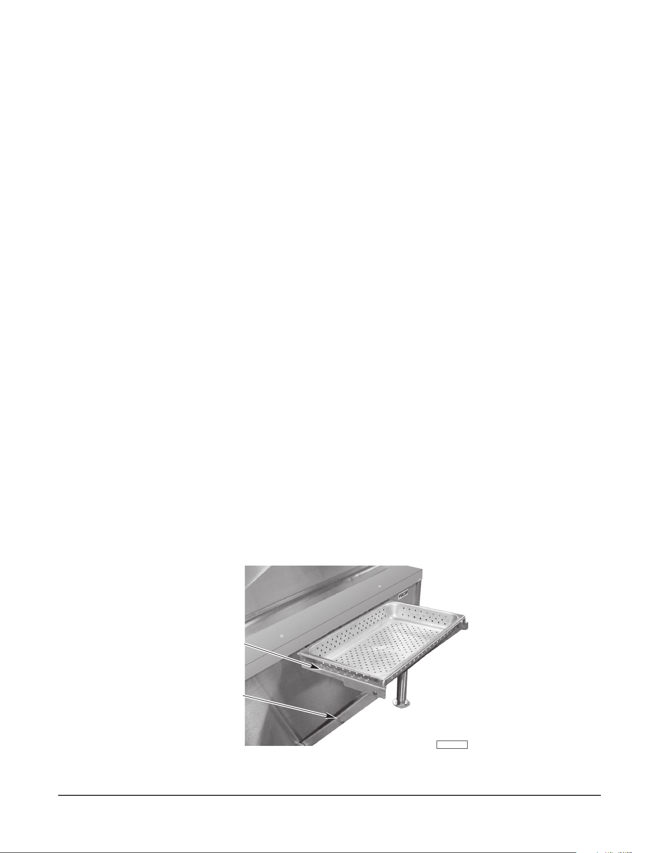
– 13 –
Fig. 4
Braisières avec levage manuel (standard)
1. La manivelle du système de levage manuel est expédiée séparément.
2. Il y a deux broches à une extrémité de la manivelle. Insérez la manivelle dans le trou du panneau de
commande de sorte que les deux broches s'engagent dans les fentes de l’accouplement du réducteur
situé derrière le panneau.
3. Tournez la manivelle dans le sens horaire pour lever la braisière et dans le sens antihoraire pour
abaisser la braisière.
4. Ce système de levage n'est pas aႇ ecté par une panne de courant et peut être utilisé pendant une
panne de courant.
5. Reportez-vous à la section ENTRETIEN de ce manuel pour les instructions de lubri¿ cation et d'entretien.
Braisières avec levage automatique (facultatif)
1. Le levage automatique ne peut pas lever la braisière à moins que le couvercle ne soit complètement
ouvert.
2. Le levage de la braisière est contrôlé par l'interrupteur à bascule gris situé sur le panneau de commande
(voir ¿ g. 3).
3. Retirez toujours la manivelle de levage manuel avant d'utiliser l’interrupteur de levage automatique.
4. Appuyez sur la partie supérieure de l'interrupteur à bascule gris pour lever la braisière et la partie
inférieure de l'interrupteur à bascule gris pour abaisser la braisière. L'interrupteur doit être maintenu
appuyé pour le levage ou l'abaissement continu de la braisière.
5. En cas de panne de courant, utilisez la manivelle (fournie séparément) pour abaisser ou lever la
braisière (comme pour les braisières avec levage manuel).
DÉCHARGEMENT DES ALIMENTS PRÉPARÉS
Toutes les braisières sont munies d'un support de cadre (¿ g. 4) pour contenir un bac de réception de
nourriture aux ¿ ns de déchargement des aliments préparés.
Tirez le support de cadre vers l'extérieur et vers le haut jusqu'à ce qu'il se verrouille. Le support acceptera
des bacs de réception de nourriture de 12 po x 20 po (30 cm x 50 cm) jusqu'à 6 po (15 cm) de profondeur.
Lorsque vous abaissez le support de cadre, appuyez sur les charnières jusqu'à ce qu'elles se plient, puis
abaissez le support
PL-41751-1
CHARNIÈRE
SUPPORT
DE CADRE
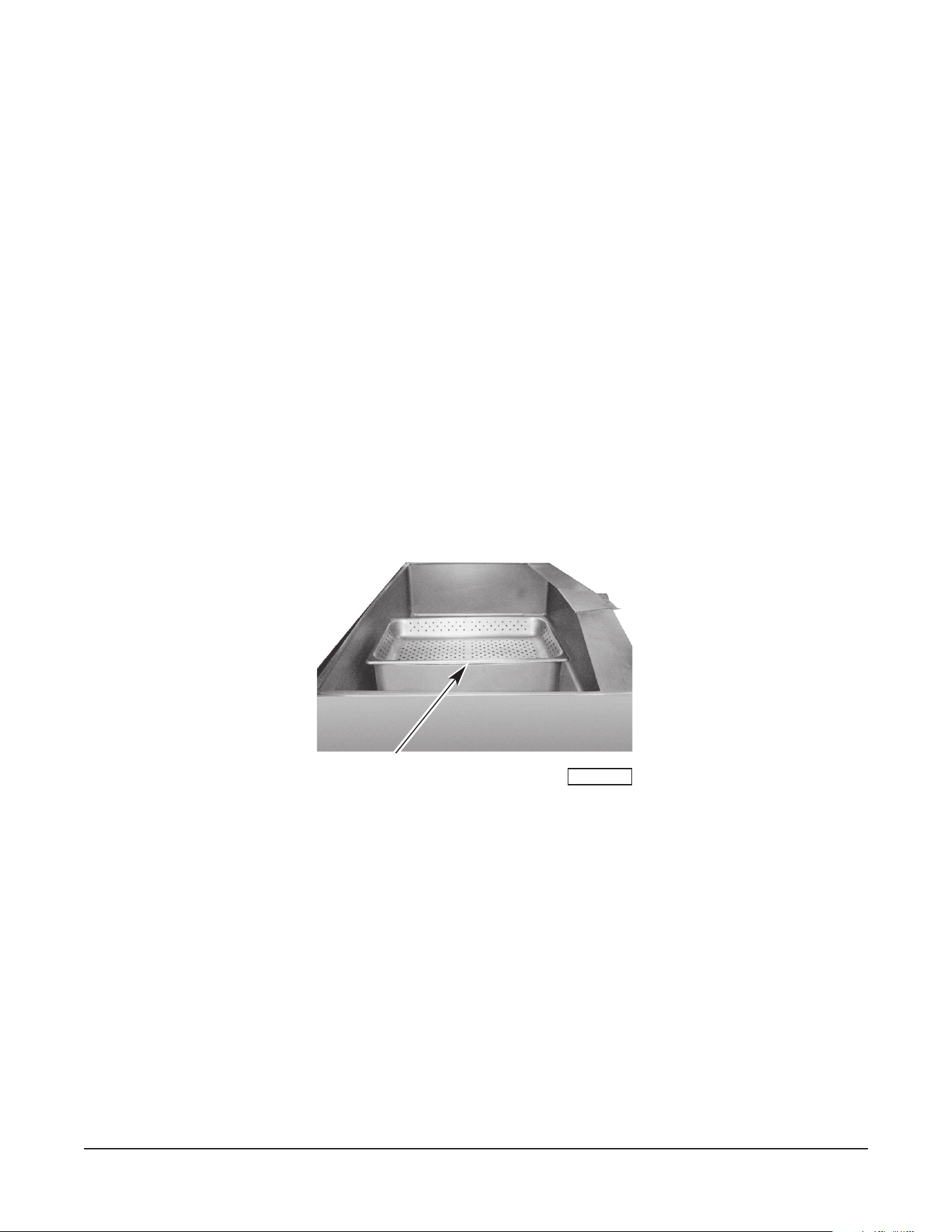
– 14 –
ACCESSOIRES DE VAPEUR (facultatifs)
Votre braisière basculante peut être utilisée pour cuire à la vapeur des aliments congelés et frais. Les
braisières de 30 gallons (114 L)
(modèles VE30 ou VG30) peuvent être chargées avec un maximum
de deux
bacs à vapeur de 12 po x 20 po x 4 po (30 cm x 50,8 cm x 10 cm). La braisière de 40 gallons
(151 L) (modèles VE40 ou VG40) acceptera jusqu'à trois bacs à vapeur de cette même taille.
Pour utiliser la braisière, remplissez la braisière de 6 à 7 gallons (23 à 26 L) d'eau (environ 2 po [5 cm]
de profondeur) pour les modèles de 30 gallons (114 L) et de 8 à 9 gallons (30 à 34 L) d'eau (environ
2 po [5 cm] de profondeur) pour les modèles de 40 gallons (151 L).
Mettez en marche la braisière. Réglez le thermostat à 212 °F (100 °C). Laissez l'eau bouillir. Réglez
ensuite le thermostat à 250 °F (121 °C) et placez soigneusement les accessoires à vapeur dans la
braisière comme indiqué à la ¿ gure 5. Placez le plat avec le produit dans l'accessoire à vapeur. Fermez
le couvercle et laissez cuire à la vapeur pendant le temps désiré.
Inspectez périodiquement le niveau d'eau à l'intérieur de la braisière. Ajoutez de l’eau si le niveau
d’eau est inférieur à
1
/2 po
(1 cm) de profondeur.
Pour utiliser la braisière comme chauႇ e-plats ou bain-marie, suivez la même procédure que pour la
cuisson à la vapeur, mais augmentez la profondeur de l'eau pour permettre au fond et aux côtés des
accessoires à vapeur d'être immergés dans l'eau. Réglez le thermostat pour la température de maintien
ou de réchauႇ ement désirée.
Les accessoires à vapeur peuvent être commandés auprès de votre revendeur.
Fig. 5
UTILISATIONS SUGGÉRÉES POUR VOTRE BRAISIÈRE
N’utilisez PAS la braisière pour la friture. Restreignez l’activité de friture au bac peu profond (¿ lm d'huile
pas plus de 1/8 po [0,3 cm] d'épaisseur) pour frire ou sauter.
Une braisière est très polyvalente. Elle peut être utilisée pour rôtir, mijoter, bouillir, sauter, saisir, frire,
réchauႇ er, maintenir au chaud, fermenter, décongeler, faire dorer, cuire à la vapeur, braiser, griller ou
cuire. Elle peut être utilisée comme une poêle surdimensionnée, comme un bain-marie, comme un four à
fermentation, comme une marmite, comme une bouilloire ou comme une cuisinière de chaleur uniforme.
Elle peut être utilisée pour la préparation des déjeuners, dîners et soupers.
Votre braisière basculante Vulcan est un appareil polyvalent qui peut être utilisé pour pratiquement
n'importe quel type de cuisson, à l'exception de la friture, à grande vitesse, en grande quantité et avec
des économies considérables de main-d'œuvre et d'énergie.
PL-41752-1
ACCESSOIRE À VAPEUR

– 15 –
ENTRETIEN ET NETTOYAGE DE L'ÉQUIPEMENT EN
ACIER INOXYDABLE
(Fourni avec l'autorisation de NAFEM. Pour de plus amples renseignements,
visitez leur site Web à www.nafem.org
Contrairement à la croyance populaire, les aciers inoxydables SONT sujets à la rouille.
La corrosion des métaux est répandue. Elle se reconnait rapidement sur le fer et l'acier sous forme de taches de
rouille disgracieuses jaune ou orange. De tels métaux sont dits « actifs » parce qu'ils se corrodent activement dans
un environnement naturel, lorsque leurs atomes combinent avec l'oxygène pour former la rouille.
Les aciers inoxydables sont des métaux « passifs », car ils contiennent d'autres métaux tels que le chrome, le
nickel et le manganèse, qui stabilisent les atomes. Les aciers inoxydables de série 400 sont appelés ferritiques,
contiennent du chrome et sont magnétiques; les aciers inoxydables de série 300 sont appelés austénitiques et
contiennent du chrome et du nickel et les aciers inoxydables de série 200 sont également austénitiques et contiennent
du manganèse, de l'azote et du carbone. Les aciers inoxydables de type austénitique ne sont pas magnétiques et
fournissent généralement une plus grande résistance à la corrosion que ceux de type ferritique.
Avec 12 à 30 % de chrome, un ¿ lm passif invisible recouvre la surface de l'acier agissant en tant que bouclier contre
la corrosion. Tant que le ¿ lm est intact et n'est pas cassé ou contaminé, le métal est passif et inoxydable. Si le ¿ lm
passif de l'acier inoxydable a été cassé, l'équipement commence à se corroder. Dans le pire des cas, il rouille.
Ennemis de l'acier inoxydable
Il y a trois choses fondamentales qui peuvent briser la couche passive de l'acier inoxydable et faciliter la corrosion.
1. Abrasion mécanique
2. Dépôts et eau
3. Chlorures
L'abrasion mécanique fait référence à toutes ces choses qui pourraient rayer la surface de l'acier comme les
plaquettes en acier, les brosses métalliques et les racloirs.
L'eau sort du robinet avec divers degrés de dureté. Selon la région du pays où vous vivez, vous pouvez avoir de
l'eau dure ou de l'eau douce. L'eau dure peut laisser des taches et lorsqu'elles sont chauႇ ées, laissent des dépôts
qui peuvent briser la couche passive et rouiller l'acier inoxydable, s'ils ne sont pas éliminés. D'autres dépôts qui
résultent de la préparation de la nourriture et de l'entretien doivent être correctement éliminés.
Les chlorures sont présents presque partout dans le monde. Ils sont dans l'eau, dans la nourriture et dans le sel de
table. L'une des sources de chlorure le plus dangereux provient des agents nettoyants domestiques et industriels.
Alors, que signi¿ e tout cela? Ne désespérez pas!
Voici quelques conseils qui peuvent aider à empêcher la rouille de l'acier inoxydable.
1. Utilisez des outils appropriés.
Lorsque vous nettoyez des produits en acier inoxydable, utilisez des outils non abrasifs. Les chiႇ ons doux
et les tampons à récurer en plastique ne nuisent pas à la couche passive de l'acier. Les plaquettes en acier
inoxydable peuvent également être utilisées, mais le mouvement de récurage doit se produire dans le sens
des marques de polissage des fabricants.
2. Nettoyez conformément aux lignes de polissage.
Certains aciers inoxydables sont livrés avec des lignes ou des grains de polissage visibles. Lorsque les lignes
visibles sont présentes, frottez toujours dans un mouvement parallèle aux lignes. Lorsque les grains ne sont
pas visibles, privilégiez la sécurité et utilisez un chiႇ on doux ou un tampon à récurer en plastique.
3. Utilisez des agents nettoyants alcalins, alcalins chlorés ou sans chlorures.
Alors que de nombreux agents nettoyants traditionnels sont chargés de chlorures, l'industrie fournit un choix
grandissant d'agents nettoyants sans chlorure. Si vous n'êtes pas sûr du contenu en chlorures de l'agent
nettoyant utilisé, communiquez avec votre fournisseur d'agent nettoyant. Si votre agent nettoyant actuel
contient des chlorures, demandez à votre fournisseur s'il a un produit alternatif. Évitez les agents nettoyants
contenant des sels quaternaires; ils peuvent aussi attaquer l'acier inoxydable et entraîner l'apparition des
piqûres et de la corrosion.

– 16 –
4. Traitez votre eau.
Même si ce n'est pas toujours pratique, l'adoucissement d'une eau dure peut contribuer de façon signi¿ cative
à réduire les dépôts. Certains ¿ ltres peuvent être installés pour retirer les éléments déplaisants et corrosifs.
Pour assurer un bon traitement de l'eau, communiquez avec un spécialiste du traitement.
5. Maintenez votre équipement alimentaire dans un état propre.
Utilisez des agents nettoyants alcalins, alcalins chlorés ou sans chlorures à la quantité recommandée.
Nettoyez fréquemment pour éviter l'accumulation de taches tenaces fermes. Si vous faites bouillir de l'eau
dans un équipement en acier inoxydable, n'oubliez pas que la seule cause la plus probable de dommages est
la présence de chlorures dans l'eau. Le chauႇ age d'agents nettoyants qui contiennent des chlorures donne
un eႇ et similaire.
6. Rincez, rincez, rincez.
Si des agents nettoyants chlorés sont utilisés, rincez et essuyez immédiatement l'équipement et les fournitures.
Plus tôt vous essuyez l'eau stagnante, surtout lorsqu'elle contient des agents de nettoyage, mieux ça vaut.
Après avoir essuyé l'équipement, laissez-le sécher à l'air; l'oxygène contribue à maintenir le ¿ lm de passivité
de l'acier inoxydable.
7. N'utilisez jamais de l'acide chlorhydrique (acide muriatique) sur l'acier inoxydable.
8. Restaurez ou passivez régulièrement l'acier inoxydable.
Tâche Agent de nettoyage Commentaires
Nettoyage de routine Savon, ammoniac,
détergent, médaillon
Appliquez à l'aide d'un chiႇ on
doux ou d'une éponge
Traces de doigt et taches Arcal 20, Lac-O-Nu Ecoshine Fournit un ¿ lm barrière
Taches tenaces et décoloration Cameo, Talc, Zud,
First Impression
Frottez dans le sens des
lignes de polissage
Graisse et acides gras, sang,
dépôts d'aliments brûlés
Easy-oႇ , DeGrease It Oven Aid Excellente élimination des
souillures sur toutes les ¿ nitions
Graisse, huile Tout bon détergent commercial Appliquez à l'aide d'un chiႇ on
doux ou d'une éponge
Restauration/passivation Bene¿ t, Super Sheen, Wichinox
Points clés à retenir
1. Les aciers inoxydables rouillent lorsque la passivité (¿ lm de protection) se décompose à la suite d'éraÀ ures,
de rayures, de dépôts et de présence de chlorures.
2. La rouille de l'acier inoxydable commence par des piqûres et des ¿ ssures.
3. Utilisez des outils appropriés. N'utilisez pas de plaquettes en acier, de brosses métalliques ou de racloirs
pour nettoyer l'acier inoxydable.
4. Utilisez des agents nettoyants non chlorés aux concentrations recommandées. N'utilisez que des
nettoyants non chlorés.
5. Adoucissez votre eau. Utilisez des ¿ ltres et des adoucisseurs au besoin.
6. Essuyez les agents nettoyants et l'eau stagnante dès que possible. Un contact prolongé peut causer
des problèmes.
Pour obtenir plus de renseignements sur la corrosion sous contrainte due aux chlorures et la façon d'éviter ce
problème, communiquez avec le fabricant de l'équipement ou le fournisseur du matériel de nettoyage.
Développé par Packer Engineering, Naperville, Ill., un laboratoire d'essai indépendant.
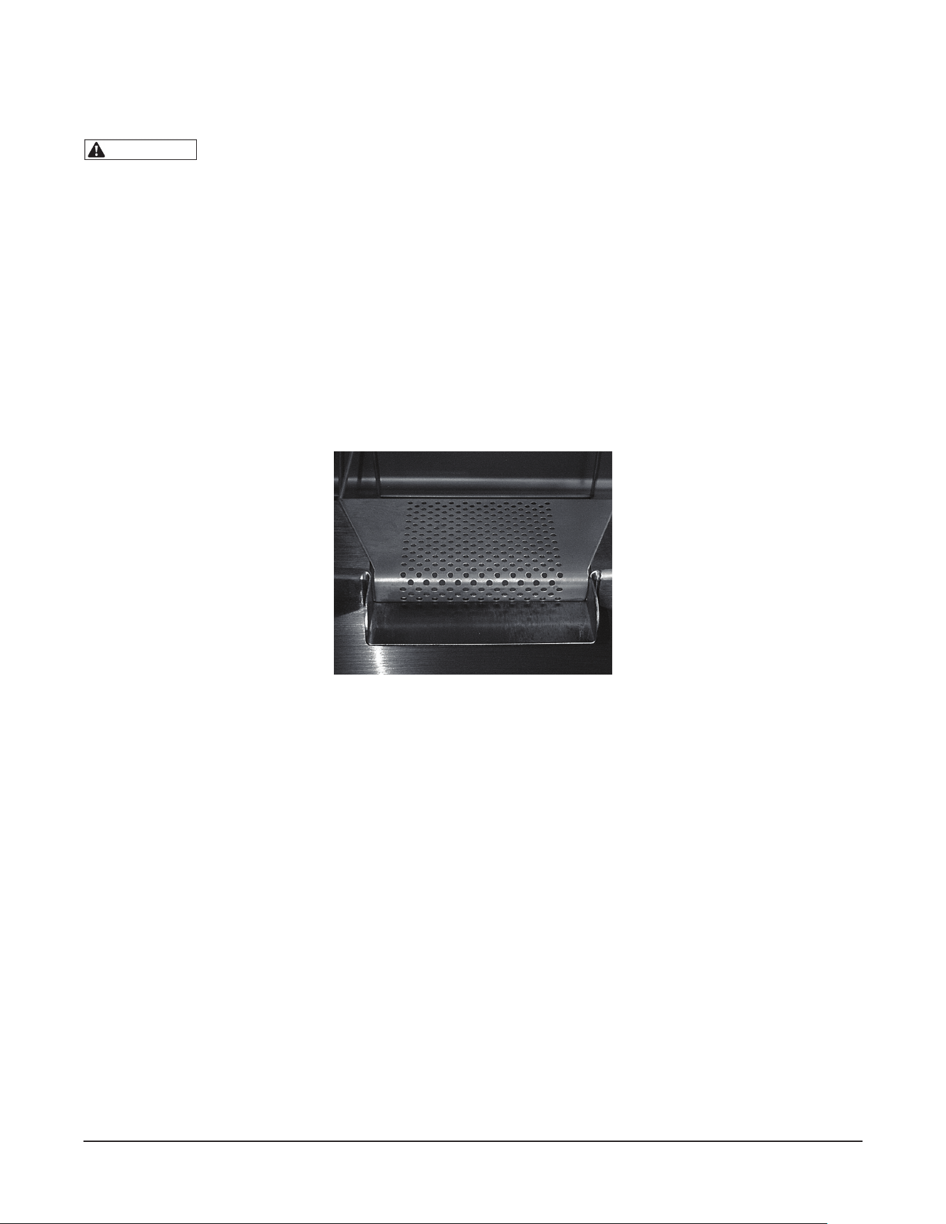
– 17 –
NETTOYAGE
AVERTISSEMENT
Coupez l'alimentation électrique à la braisière et suivez les procédures de verrouillage/
d'étiquetage avant de nettoyer.
Nettoyez votre braisière régulièrement. Gardez la surface de la plaque propre. Pour produire des produits
parfaitement cuits et parfaitement braisés, gardez la surface de la braisière exempte de graisse carbonisée.
La graisse carbonisée sur la surface empêche le transfert de chaleur de la surface de la braisière à la
nourriture. Ceci entraîne un brunissement irrégulier et une perte d'eႈ cacité de cuisson. Le pire de tout, la
graisse carbonisée a tendance à s'accrocher aux aliments, leur donnant une apparence très insatisfaisante
et peu appétissante.
Après chaque utilisation
Nettoyez la surface de la braisière avec une brosse ou une spatule À exible.
Retirez le passoire (¿ g. 6) sur le bec verseur de la braisière en la tirant vers l'arrière de la braisière.
Nettoyez la passoire dans un évier. Rincez abondamment la braisière avec un chiႇ on doux et propre.
Replacez la passoire.
Fig. 6
Une fois par jour
Nettoyer soigneusement le dos, les côtés et l'avant de la braisière. Nettoyez également les surfaces
intérieures et extérieures du couvercle.
Une fois semaine
Nettoyez la surface de la braisière à fond. Si nécessaire, utilisez un bloc ou une brosse à grille sur la
surface. Du détergent peut être utilisé sur la surface de la braisière pour aider à la nettoyer, mais assurez-
vous que le détergent est complètement enlevé.
Nettoyez les autres surfaces en acier inoxydable avec un chiႇ on humide et polissez avec un chiႇ on
doux et sec. Pour éliminer toute décoloration, utilisez un agent nettoyant non abrasif. Si vous utilisez la
braisière très souvent, envisagez de passer par les procédures de nettoyage hebdomadaires plus d'une
fois par semaine.
Lorsque vous nettoyez la braisière, il est utile de remplir la braisière d'environ 10 gallons (38 L) d'eau
chaude et d'ajouter du détergent. Après le nettoyage, soulevez la braisière pour vider toute l'eau (placez
un seau ou un récipient sous le bec verseur). Répétez ensuite ces étapes pour le rinçage à l'eau propre.
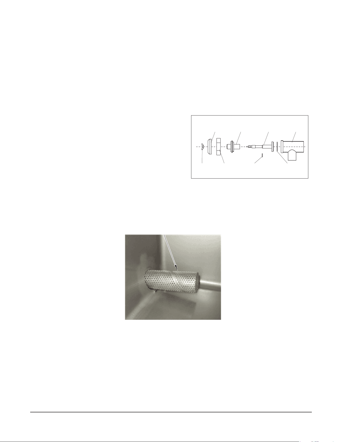
– 18 –
INSTRUCTIONS DE NETTOYAGE DU ROBINET DE VIDAGE
Quotidiennement après chaque utilisation
Retirez l'ensemble de tige du robinet de vidage pour le nettoyage (Fig. 7).
1. Tournez la poignée du robinet dans le sens antihoraire jusqu'à la butée d'arrêt.
2. Retirez la poignée du robinet vers l’extérieur jusqu’à la butée.
3. Tournez le grand écrou hexagonal dans le sens antihoraire jusqu'à ce que l'ensemble de tige de robinet
soit desserré.
4. Tirez l'ensemble tout droit vers l'extérieur du corps du robinet.
5. Retirez l'écrou à oreilles et la poignée. Dévissez la tige du robinet du chapeau.
6. Lavez le corps et la tige du robinet avec un savon doux et de l'eau, puis rincez. Assurez-vous que tous
les résidus d'aliment sont enlevés de l'intérieur du corps du robinet.
7. Ne remettez pas les pièces ensemble. Laissez-les sécher.
Installation de l'ensemble du robinet de vidage :
1. Appliquez du lubri¿ ant au ¿ letage de la tige du
robinet, au joint torique, au bouchon en caoutchouc
et aux ¿ letages des grands écrous hexagonaux.
2. Vissez la tige du robinet dans le chapeau jusqu'à
ce que la tige peut être tirée à travers le chapeau.
3. Insérez la tige dans le corps du robinet.
4. Installez le grand écrou hexagonal et serrez à la
main.
5. Installez la poignée, la rondelle de blocage et
l'écrou à oreilles sur la tige du robinet.
6. Tournez la poignée du robinet dans le sens horaire
jusqu'à la fermeture. Ne serrez pas excessivement.
Fig. 8
Fig. 7
Poignée
Écrou
à oreilles
Écrou
hexagonal
Joint torique
de la tige
Joint torique de
la tige de robinet
Chapeau
Tige de
robinet
Corps du
robinet
INSTALLATION CORRECTE DE
LA CRÉPINE POUR LA VANNE DE
PRÉLÈVEMENT EN OPTION

– 19 –
DIRECTIVES DE CUISSON (mesures impériales)
Les directives données ci-dessous sont des quantités suggérées, des réglages de température et des
nombres estimés de commandes par charge et par heure. Lorsque deux températures sont données, la
première consiste à démarrer la cuisson du produit et la seconde à terminer la cuisson du produit.
Les températures suivantes devraient être utilisées :
Température
(°F)
Mijoter 200 max.
Sauter 225 à 275
Saisir 300 à 350
Faire frire 325 à 375
Griller 350 à 425
ALIMENT
PORTION
TAILLE
TEMP.
(°F)
LOTS
PAR
HEURE
VG30/VE30
PAR CHARGE
VG40/VE40
PAR CHARGE
QTÉ PORTIONS QTÉ PORTIONS
DÉJEUNER
Bacon 3 tranches 350 12 2 lb 10 3 lb 15
Œufs
– bouilli – dur 1 œuf 225 5 50 œufs 50 75 œufs 75
– bouilli – à la coque 1 œuf 225 8 50 œufs 50 75 œufs 75
– poêlé 1 œuf 400 4 30 œufs 30 45 œufs 45
– poché 1 œuf 225 5 36 œufs 36 60 œufs 60
– brouillé 1
1
/2 œufs 300 – 200 1 18 gal 720 28 gal 1100
Pain doré 3 tranches 425 7 35 tranches 12 50 tranches 17
Gruau régulier
1
/2 tasse 250 2
20 lb (100
tasses)
500 40 lb (200
tasses)
1 000
Crêpes 2 chaque 400 10 30 ch 15 50 ch 25
POISSON
Myes 1 chop 400 10 10 ptes 20 15 ptes 30
Fricadelle de poisson 2 à 3 oz 400 5 70 – 3 oz 35 110 – 3 oz 55
Filet d'égle¿ n 4 oz 400 4 60 – 4 oz 60 90 – 4 oz 90
Darne de À étan 5 oz 425 3 60 – 4 oz 60 90 – 4 oz 90
Homard 1 – 1 lb 350 4 20 – 1 lb 20 30 – 1 lb 30
Espadon 5 oz 425 3 50 – 5 oz 50 75 – 5 oz 75
SAUCES ET SOUPES
Sauce brune 1 oz 350 – 200 2 30 gal 3 840 40 gal 5120
Sauce crème 2 oz 250 – 175 1 30 gal 1 920 40 gal 2 560
Potage crème 6 oz 200 1 30 gal 640 40 gal 853
Soupe à l'oignon 6 oz 225 1 30 gal 640 40 gal 853
Sauce à la viande 4 oz 350 – 200 1 30 gal 960 40 gal 1 280

– 20 –
ALIMENT
PORTION
TAILLE
TEMP.
(°F)
LOTS
PAR
HEURE
VG30/VE30
PAR CHARGE
VG40/VE40
PAR CHARGE
QTÉ PORTIONS QTÉ PORTIONS
LÉGUMES
CONSERVES 3 oz 400 6 30 lb 125 45 lb 200
FRAIS
Haricots, jaune, vert 3 oz 400 3 25 lb 125 50 lb 250
Betteraves 3 oz 400 1 30 lb 125 60 lb 300
Brocoli 3 oz 400 3 25 lb 125 40 lb 200
Chou 3 oz 400 5 20 lb 80 30 lb 125
Carottes 3 oz 400 2 35 lb 150 70 lb 300
Chou-À eur 3 oz 250 5 15 lb 75 25 lb 125
Maïs 1 épi 400 8 50 épis 50 75 épis 75
Pommes de terre 3 oz 400 2 40 lb 200 60 lb 300
Épinards 4 oz 250 10 6 lb 25 9 lb 35
Navets 4 oz 400 2 20 lb 100 30 lb 150
CONGELÉ
Haricots verts à la française 3 oz 400 6 15 lb 60 22
1
/2 lb 90
Haricots de Lima 3 oz 250 4 15 lb 60 22
1
/2 lb 90
Brocoli 3 oz 400 8 12 lb 50 18 lb 75
Carottes tranchées 3 oz 250 6 15 lb 60 22
1
/2 lb 90
Petites carottes entières 3 oz 250 3 15 lb 50 22
1
/2 lb 90
Maïs 3 oz 250 18 15 lb 50 22
1
/2 lb 90
Petits oignons entiers 3 oz 250 7 15 lb 50 22
1
/2 lb 90
Pois 3 oz 400 10 15 lb 75 22
1
/2 lb 110
Épinards 3 oz 400 3 15 lb 75 22
1
/2 lb 110
DESSERTS, PUDDINGS, SAUCES SUCRÉES
Sauce caramel 1 oz 200 1 30 gal 3 840 40 gal 5120
Cobbler cerise 3 oz 200 1 30 gal 1 280 40 gal 1 707
Sauce au chocolat 1 oz 200 1 30 gal 3 840 40 gal 5120
Pudding de fécule de maïs 4 oz 200 1 30 gal 960 40 gal 1 280
Gélatine aux fruits 3 oz 250 2 30 gal 1 280 40 gal 1 707
VIANDE – VOLAILLE
Bacon 3 tranches 350 12 2 lb 10 3 lb 15
BŒUF
Chop suey américain 6 oz 400 – 225 2 30 gal 640 40 gal 853
Ragoût de bœuf 8 oz 300 — 30 gal 480 40 gal 640
Hachis de bœuf 5 oz 400 5 20 lb 60 30 lb 90
Hamburger au fromage 3 oz 300 12 7 lb 35 10 lb 50
Hamburger 3 oz 300 15 7 lb 35 10 lb 50
Boulettes de viande 1 oz 400 – 225 3 12
1
/2 lb 65 18 lb 100
Morceau à braiser 2 oz 350 – 200 120 lb 500 180 lb 750
Bifteck Salisbury 5 oz 400 3 16 lb 50 24 lb 75
Bifteck de surlonge 6 oz 400 5 15 lb 40 22
1
/2 lb 60
Bifteck à la suisse 4 oz 300 – 200 1 25 lb 110 40 lb 160

– 21 –
ALIMENT
PORTION
TAILLE
TEMP.
(°F)
LOTS
PAR
HEURE
VG30/VE30
PAR CHARGE
VG40/VE40
PAR CHARGE
QTÉ PORTIONS QTÉ PORTIONS
POULET
Poêlé 2 –
1
/4 350 3 50 morceaux 25 80 morceaux 40
Entier 2 oz 350 – 200 16 – 5 lb 200 24 – 5 lb 265
SAUCISSES FUMÉES
Grillée 2 oz 300 8 22 lb 176 33 lb 264
Bouillie 2 oz 250 12 16 lb 128 25 lb 200
PORC
Tranche de jambon 3 oz 400 8 10 lb 50 15 lb 75
Côtes de porc 5 oz 350 4 15 lb 50 25 lb 75
Chapelet de saucisses 3 chapelets 350 7 30 lb 120 45 lb 180
DINDE
Hors carcasse 2 oz 400 – 200 — 3–26 à 30 lb 200 4–26 à 30 lb 275
Sur carcasse 2 oz 400 – 200 — 4-16 à 20 lb 175 6-16 à 20 lb 265
DIVERS
Sandwich au fromage fondu 1 sandwich 400 8 40 sandwichs 40 50 sandwichs 50
Macaroni au fromage 8 oz 200 2 30 gal 480 40 gal 640
Riz 4 oz 350 – 225 1 20 lb (non
cuit)
320 40 lb (non
cuit)
650
Spaghetti 4 oz 350 – 225 2 8 lb (non cuit) 200 12 lb (non
cuit)
300

– 22 –
DIRECTIVES DE CUISSON (mesures métriques)
Les directives données ci-dessous sont des quantités suggérées, des réglages de température et des
nombres estimés de commandes par charge et par heure. Lorsque deux températures sont données, la
première consiste à démarrer la cuisson du produit et la seconde à terminer la cuisson du produit.
Les températures suivantes devraient être utilisées :
Température (°C)
Mijoter 93,3 max.
Sauter 107 à 135
Saisir 149 à 177
Faire frire 163 à 191
Griller 177 à 218
ALIMENT
PORTION
TAILLE
TEMP.
(°C)
LOTS
PAR
HEURE
VG30/VE30
PAR CHARGE
VG40/VE40
PAR CHARGE
QTÉ PORTIONS QTÉ PORTIONS
DÉJEUNER
Bacon 3 tranches 177 12 0,9 kg 10 1,4 kg 15
Œufs
– bouilli – dur 1 œuf 107 5 50 œufs 50 75 œufs 75
– bouilli – à la coque 1 œuf 107 8 50 œufs 50 75 œufs 75
– poêlé 1 œuf 204 4 30 œufs 30 45 œufs 45
– poché 1 œuf 107 5 36 œufs 36 60 œufs 60
– brouillé 1
1
/2 œufs 149 – 93 1 68 L 720 106 L 1100
Pain doré 3 tranches 218 7 35 tranches 12 50 tranches 17
Gruau régulier 118 mL 121 2 9 kg 500 18 kg 1 000
Crêpes 2 chaque 204 10 30 ch 15 50 ch 25
POISSON
Myes 473 mL 204 10 9 L 20 14 L 30
Fricadelle de poisson 57 à 85 g 204 5 70 – 85 g 35 110 – 85 g 55
Filet d'égle¿ n 113 g 204 4 60 – 113 g 60 90 – 113 g 90
Darne de À étan 142 g 218 3 60 – 113 g 60 90 – 113 g 90
Homard 1 – 0,5 kg 177 4 20 – 0,5 kg 20 30 – 0,5 kg 30
Espadon 142 g 218 3 50 – 142 g 50 75 – 142 g 75
SAUCES ET SOUPES
Sauce brune 28 g 177 – 93 2 114 L 3 840 151 L 5120
Sauce crème 57 g 121 – 79 1 114 L 1 920 151 L 2 560
Potage crème 170 g 93 1 114 L 640 151 L 853
Soupe à l'oignon 170 g 107 1 114 L 640 151 L 853
Sauce à la viande 113 g 177 – 93 1 114 L 960 151 L 1 280

– 23 –
ALIMENT
PORTION
TAILLE
TEMP.
(°C)
LOTS
PAR
HEURE
VG30/VE30
PAR CHARGE
VG40/VE40
PAR CHARGE
QTÉ PORTIONS QTÉ PORTIONS
LÉGUMES
CONSERVES 85 g 204 6 14 kg 125 20 kg 200
FRAIS
Haricots, jaune, vert 85 g 204 3 11 kg 125 23 kg 250
Betteraves 85 g 204 1 14 kg 125 27 kg 300
Brocoli 85 g 204 3 11 kg 125 18 kg 200
Chou 85 g 204 5 9 kg 80 14 kg 125
Carottes 85 g 204 2 16 kg 150 32 kg 300
Chou-À eur 85 g 121 5 7 kg 75 11 kg 125
Maïs 1 épi 204 8 50 épis 50 75 épis 75
Pommes de terre 85 g 204 2 18 kg 200 27 kg 300
Épinards 113 g 121 10 3 kg 25 4 kg 35
Navets 113 g 204 2 9 kg 100 14 kg 150
CONGELÉ
Haricots verts à la française 85 g 204 6 7 kg 60 10 kg 90
Haricots de Lima 85 g 121 4 7 kg 60 10 kg 90
Brocoli 85 g 204 8 5 kg 50 8 kg 75
Carottes tranchées 85 g 121 6 7 kg 60 10 kg 90
Petites carottes entières 85 g 121 3 7 kg 50 10 kg 90
Maïs 85 g 121 18 7 kg 50 10 kg 90
Petits oignons entiers 85 g 121 7 7 kg 50 10 kg 90
Pois 85 g 204 10 7 kg 75 10 kg 110
Épinards 85 g 204 3 7 kg 75 10 kg 110
DESSERTS, PUDDINGS, SAUCES SUCRÉES
Sauce caramel 28 g 93 1 114 L 3 840 151 L 5 120
Cobbler cerise 85 g 93 1 114 L 1 280 151 L 1 707
Sauce au chocolat 28 g 93 1 114 L 3 840 151 L 5 120
Pudding de fécule de maïs 113 g 93 1 114 L 960 151 L 1 280
Gélatine aux fruits 85 g 121 2 114 L 1 280 151 L 1 707
VIANDE – VOLAILLE
Bacon 3 tranches 177 12 0,9 kg 10 1 kg 15
BŒUF
Chop suey américain 170 g 204 – 107 2 114 L 640 151 L 853
Ragoût de bœuf 0,2 kg 149 — 114 L 480 151 L 640
Hachis de bœuf 142 g 204 5 9 kg 60 14 kg 90
Hamburger au fromage 85 g 149 12 3 kg 35 5 kg 50
Hamburger 85 g 149 15 3 kg 35 5 kg 50
Boulettes de viande 28 g 204 – 107 3 6 kg 65 8 kg 100
Morceau à braiser 57 g 177 – 93 54 kg 500 82 kg 750
Bifteck Salisbury 142 g 204 3 7 kg 50 11 kg 75
Bifteck de surlonge 170 g 204 5 7 kg 40 10 kg 60
Bifteck à la suisse 113 g 149 – 93 1 11 kg 110 18 kg 160

– 24 –
ALIMENT
PORTION
TAILLE
TEMP.
(°C)
LOTS
PAR
HEURE
VG30/VE30
PAR CHARGE
VG40/VE40
PAR CHARGE
QTÉ PORTIONS QTÉ PORTIONS
POULET
Poêlé 2 –
1
/4 177 3 50 morceaux 25 80 morceaux 40
Entier 57 g 177 – 93 16 – 2 kg 200 24 – 2 kg 265
SAUCISSES FUMÉES
Grillée 57 g 149 8 10 kg 176 15 kg 264
Bouillie 57 g 121 12 7 kg 128 11 kg 200
PORC
Tranche de jambon 85 g 204 8 5 kg 50 7 kg 75
Côtes de porc 142 g 177 4 7 kg 50 11 kg 75
Chapelet de saucisses 3 chapelets 177 7 14 kg 120 10 kg 180
DINDE
Hors carcasse 57 g 204 – 93 — 3 –
12 à 14 kg
200 4 – 12 à 14 kg 275
Sur carcasse 57 g 204 – 93 — 4 – 7 à 9 kg 175 6 – 7 à 9 kg 265
DIVERS
Sandwich au fromage fondu 1 sandwich 204 8 40 sandwichs 40 50 sandwichs 50
Macaroni au fromage 0,2 kg 93 2 114 L 480 151 L 640
Riz 113 g 177 – 107 1 9 kg (non cuit) 320 18 kg (non
cuit)
650
Spaghetti 113 g 177 – 107 2 4 kg (non cuit) 200 5 kg (non cuit) 300
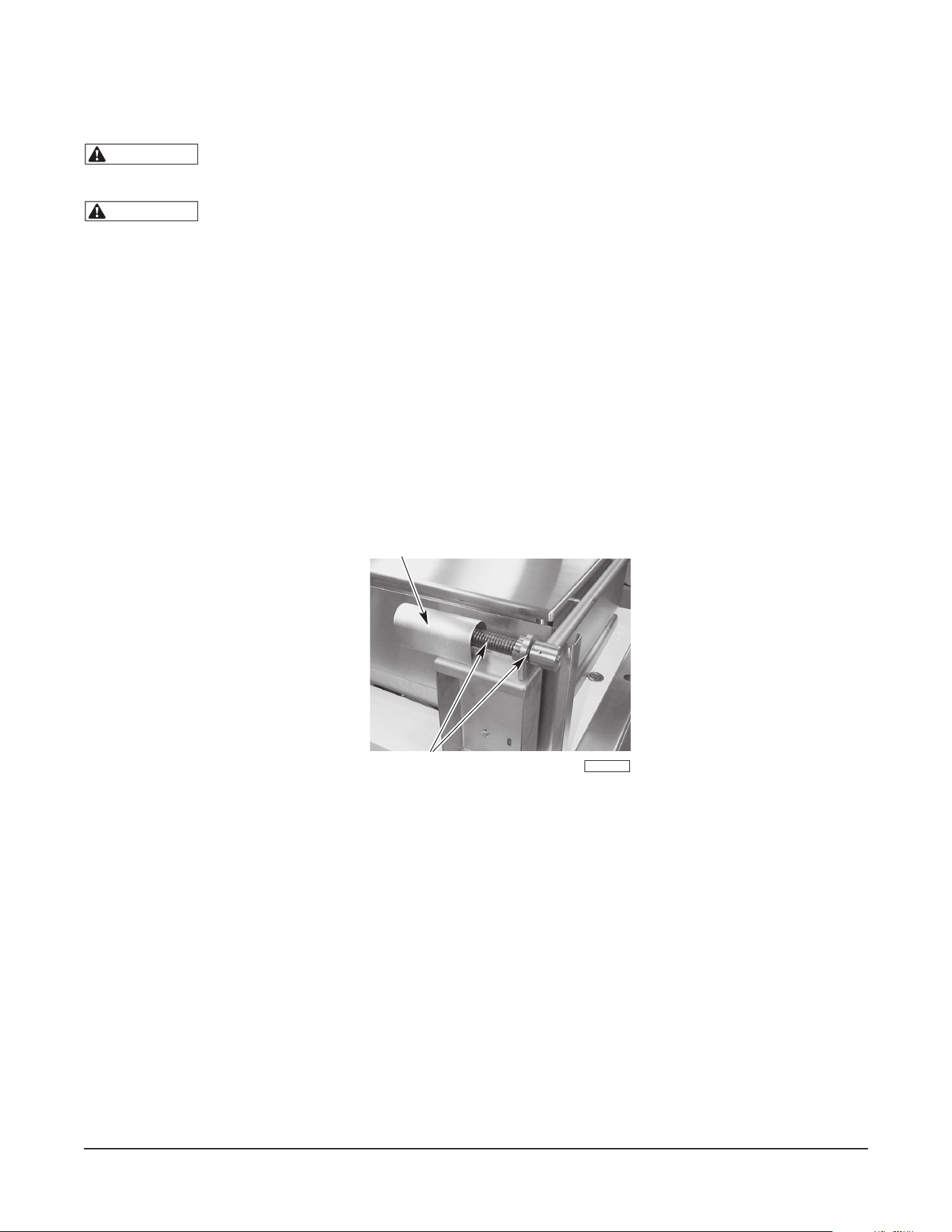
– 25 –
ENTRETIEN
AVERTISSEMENT
La braisière et ses pièces sont chaudes. Faites attention lorsque vous utilisez,
nettoyez ou entretenez la braisière.
AVERTISSEMENT
Coupez l'alimentation électrique à la braisière et suivez les procédures de verrouillage/
d'étiquetage avant d’eႇ ectuer l’entretien.
LUBRIFICATION
Mécanisme du couvercle
1. Le mécanisme de levage du couvercle et le ressort de tension sont situés derrière le dosseret
(panneau de tôle derrière la braisière) sur les deux coins arrière gauche et droit de la braisière.
2. Forcez l’ouverture de la cache et enlevez-la (¿ g. 9).
3. Pour assurer un bon fonctionnement du couvercle, lubri¿ ez ces mécanismes avec 8 à 10 gouttes
d'huile lubri¿ ante tous les 6 mois. Placez quelques gouttes d'huile entre le bras du couvercle et le
bloc ¿ xe, et quelques gouttes sur l'arbre autour duquel le ressort est enroulé.
4. Replacez la cache pour maintenir le bon fonctionnement.
Fig. 9
RÉGLAGES
Au moins deux fois par an, demandez à un technicien Vulcan autorisé de nettoyer et de régler la braisière
basculante a¿ n d’assurer une performance maximale.
CONDUIT DE FUMÉE
Une fois refroidi, véri¿ ez chaque année le conduit de fumée. Nettoyez le conduit de toute accumulation
de graisse ou d'autres obstructions pouvant aႇ ecter l'écoulement des gaz de combustion de la braisière.
RENSEIGNEMENTS SUR L’ENTRETIEN ET LES PIÈCES
Pour obtenir des renseignements sur l’entretien et les pièces concernant la braisière, communiquez avec
l’agence de service Vulcan de votre région (reportez-vous à la liste fournie avec la braisière) ou avec le
service auxiliaire de Vulcan à l’adresse ou au numéro de téléphone indiqués sur la page de couverture
de ce manuel.
PL-41754-1
LUBRIFIER
CACHE

– 26 –
DÉPANNAGE
BRAISIÈRES À GAZ
Problème Cause possible
Les brûleurs ne s'allument
pas.
1. L'alimentation électrique est coupée.
2. L'alimentation en gaz de la braisière est coupée.
3. Le thermostat est éteint.
4. Le robinet d’alimentation en gaz est fermé.
5. La braisière n'est pas dans sa position la plus basse.
6. Problème avec le système de commande du gaz. Contactez
votre technicien d’entretien agréé Vulcan.
Les brûleurs produisent des
dépôts de carbone.
1. Le cadre de la braisière n’est pas de niveau.
2. Ori¿ ces de mauvaises tailles.
3. L'air du brûleur n'est pas réglé correctement.
4. Mauvaise alimentation en gaz
5. Pression incorrecte à l'alimentation.
BRAISIÈRES ÉLECTRIQUES
Problème Cause possible
Les éléments chauႇ ants ne
s'allument pas.
1. L'alimentation électrique est coupée.
2. Le thermostat est éteint.
3. Fusible grillé dans le boîtier électrique sur site.
4. La braisière n'est pas dans sa position la plus basse.
5. Problème avec les circuits de commande. Contactez votre
technicien d’entretien agréé Vulcan.
FORMULAIRE 31227 Rév. C (septembre 2020) IMPRIMÉ AUX É.-U.