1
User's Manual
———— Quick Operation Guide ————
M200

1
Index
1. Product Introduction .............................................................................................................................3
2. Notes..........................................................................................................................................................3
3. Product Appearance and Functional Button Introduction...................................................... 4
3.1. Product Description ...........................................................................................................................4
4. Product Parameters and Accessories ..............................................................................................5
4.1. Product Parameters ........................................................................................................................... 5
4.2. Product Accessories ...........................................................................................................................5
4.3. Support Agreement ...........................................................................................................................5
5. Vehicle Inspection..................................................................................................................................6
6. Page Menu Introduction ..................................................................................................................... 6
6.1. Diagnostic Menu .................................................................................................................................6
6.1.1. Code Reading ...................................................................................................................................7
6.1.2. decode code .....................................................................................................................................8
6.1.3. Freezing Frame ................................................................................................................................ 8
6.1.4 I/M Ready Status .............................................................................................................................. 8
6.1.5. Vehicle Information ........................................................................................................................9
6.1.6 Data Flow ............................................................................................................................................ 9
6.1.7. pattern 6 .......................................................................................................................................... 10
6.1.8. Oxygen Sensor Testing ...............................................................................................................10
6.1.9. pattern 8 .......................................................................................................................................... 11
6.2. Fault Code Inquiry ............................................................................................................................11
6.3. Diagnosis.............................................................................................................................................12
6.4. Data Center ........................................................................................................................................ 17
6.4.1. Cloud Printing ................................................................................................................................18
6.4.2. Performance Testing ....................................................................................................................19
6.4.3. Battery Testing...............................................................................................................................20
6.5. Upgrade ...............................................................................................................................................21
6.6.AI agent.................................................................................................................................................22
6.7. Settings ................................................................................................................................................ 24
7. Exemption Conditions ........................................................................................................................24

2
1.
Product Introduction
This is an enhanced automotive code reader that supports OBD II/EOBD
standard protocols for all vehicle models, as well as proprietary protocols for
the engine, transmission, ABS, and SRS. It is plug-and-play, allowing you to
quickly read vehicle fault information and parameters. It can also perform
in-depth diagnostics on four systems and execute clear-code commands,
making it a more comprehensive diagnostic tool. Please read the product
manual carefully before use. Thank you.
2.
Precautions
1. Do not use abrasive cleaners to clean this product.
2. Do not heat the product or expose it to open flames.
3. Do not leave the product under direct sunlight for extended periods.
4. Do not attempt to disassemble or modify the product, as it contains no
user- serviceable components.
5. If you do not plan to use the product for a long time, store it in a dry
environment away from extreme temperatures and dust.
3
3. Product Appearance and Button Functions
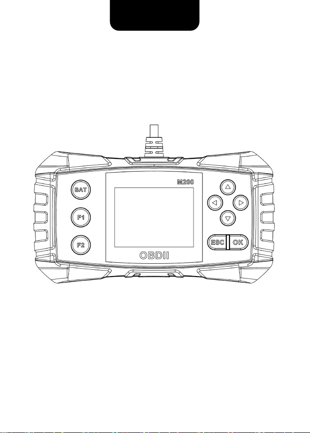
3.1. Product Diagram
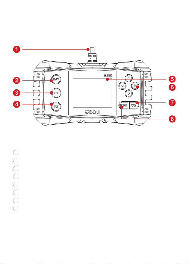
1 Product connection cable – connects to the vehicle’s OBD port.
2 Quick access to battery test.
3 Quick access to I/M readiness status.
4 Quick access to AI assistant.
5 Display screen.
6 Directional keys.
7 Confirm key.
8 Return/Exit key.

4
4. Product Specifications and Accessories
4.1. Product Parameter
Working voltage: DC 9–16V
Working environment: -20~60°C
Working current: 116–176 mA
Storage temperature: -20~60°C
Supports 13 languages: English, German, French, Spanish, Italian,
Portuguese, Russian, Polish, Japanese, Chinese, Arabic, Dutch, and
Romanian.
4.2. Accessories
Host *1 User Manual *1 Storage pouch *1
4.3. Supported Protocols
1. SAE J1850 PWM (41.6Kbaud)
2. SAE J1850 VPW (10.4Kbaud)
3. ISO9141-2 (5 baud init, 10.4Kbaud)
4. ISO14230-4 KWP (5 baud init, 10.4 Kbaud)
5. ISO14230-4 KWP (fast init, 10.4 Kbaud)
6. ISO15765-4 CAN (11bit ID, 500 Kbaud)
7. ISO15765-4 CAN (29bit ID, 500 Kbaud)
8. ISO15765-4 CAN (11bit ID, 250 Kbaud)
9. ISO15765-4 CAN (29bit ID, 250 Kbaud)
5
5. Vehicle Testing
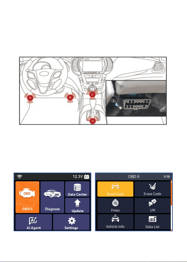
First locate the vehicle’s OBD port. The position of the OBD port varies by
vehicle (it is usually on the lower left side of the dashboard, above the
accelerator pedal; for other models, see the diagram below). After plugging
in the reader, start the vehicle.
6. Page Menu Introduction
6.1. Diagnostic Menu
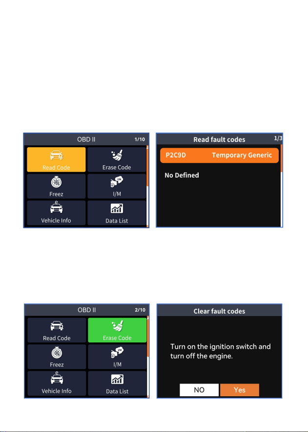
After connecting the vehicle, enter the main page, select the "OBDII" menu,
and press the OK key to access the test function page. This menu contains
nine test functions, which can be selected using the arrow keys.
6
6.1.1. Reading Frame
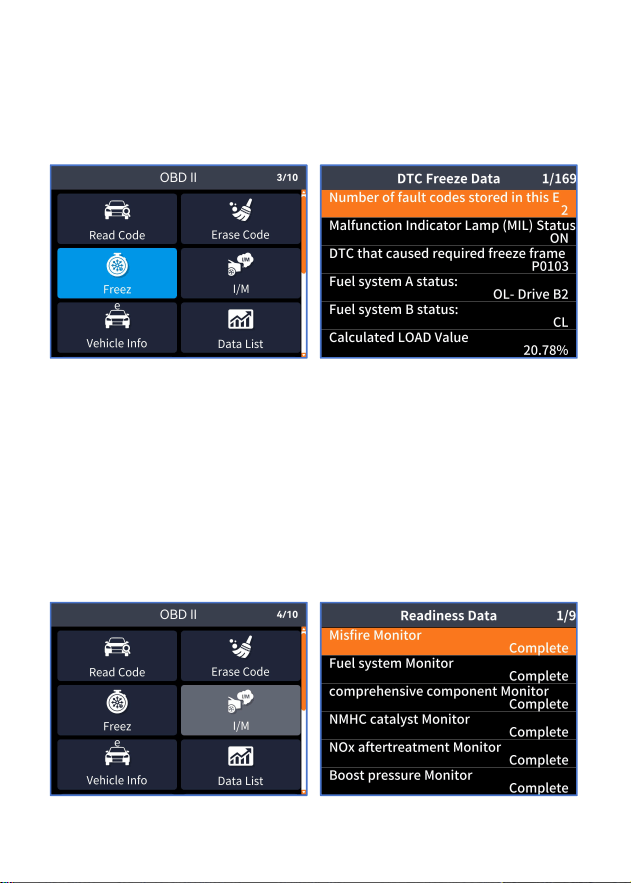
Select the code reading function, and the product will diagnose the
vehicle engine system.
If the vehicle has an engine fault, the engine fault code and its
description will be read.
If multiple fault codes are present, use the up/down buttons to navigate
through them.
Press ESC to return.
6.1.2. Clear Code
Selecting "Clear Code" will display a confirmation message. After
confirming the clearance, the engine fault light will turn off, indicating
successful code clearance. If the clearance fails, perform it with the
engine powered off.
7
6.1.3. Freeze Frame
A freeze frame refers to the snapshot data automatically recorded by the
vehicle's computer when a fault code appears in the emission system. This is
a valuable feature that helps identify the root cause of the malfunction.
6.1.4. I/M Ready Condition
The I/M readiness function checks whether the vehicle monitor is OK or N/A.
This operation is performed during specific driving scenarios (each monitor
has its own designated driving conditions and required duration).
OK indicates completion of monitoring tests
INC indicates not ready
N/A indicates that the vehicle does not support this monitoring feature.
8
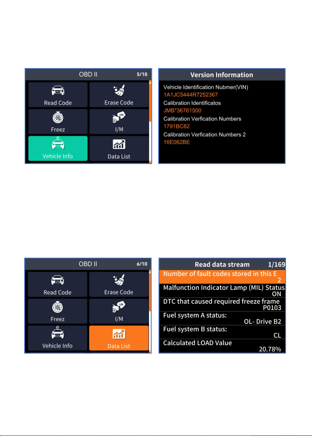
6.1.5. Vehicle Information
You can view information such as the vehicle identification number,
calibration identification code, and verification number.
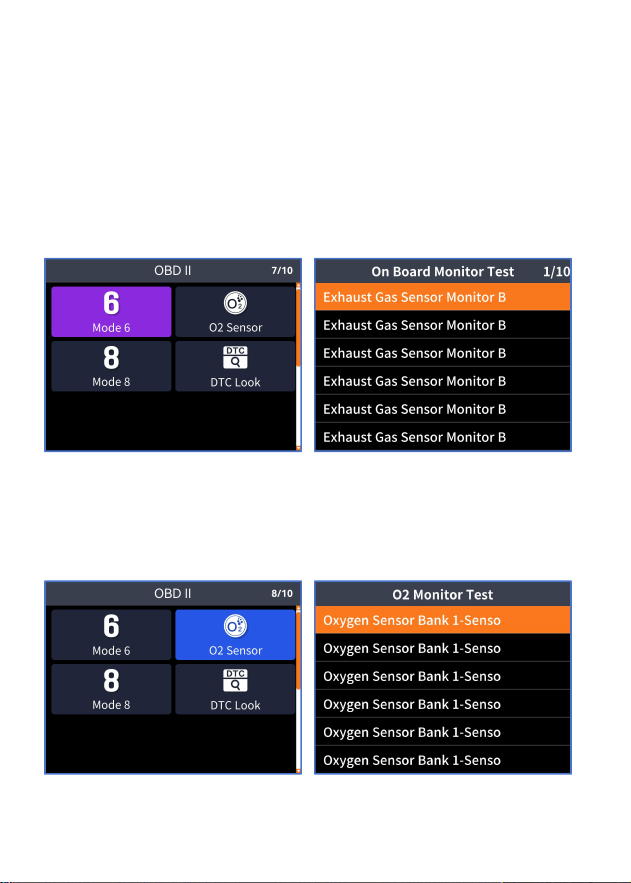
6.1.6. Data List
Upon entering the data stream, the product reads the real-time engine data.
Green indicates the reference value of the data stream, while red signifies an
anomaly. An upward arrow indicates exceeding the maximum value, and a
downward arrow indicates exceeding the minimum value.
9
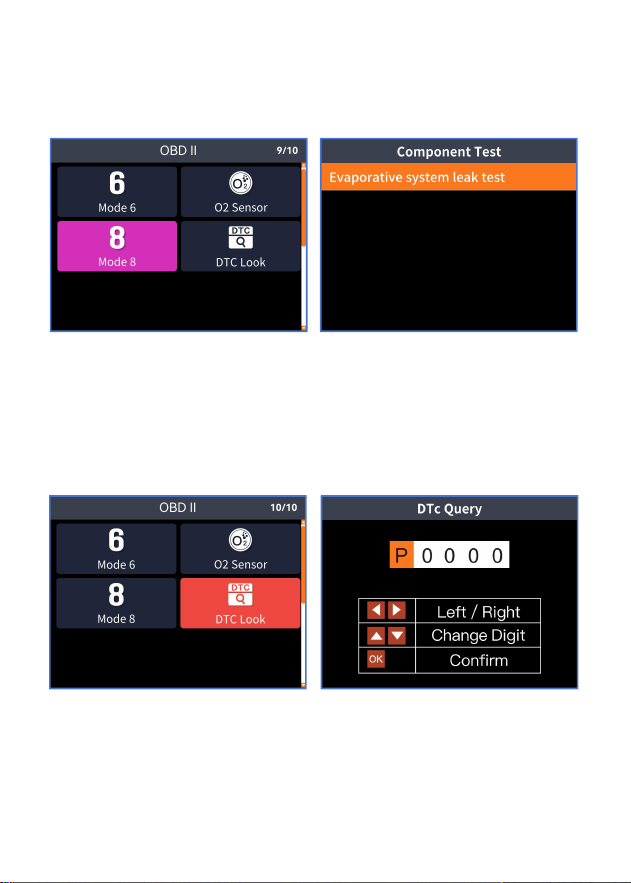
6.1.7. Mode 6
Mode 6 provides raw test result data for discontinuous testing of
emission-related system components, such as exhaust sensors, catalytic
converters, variable valve timing systems, exhaust sensor heaters, and
heated catalytic converters, requiring vehicle support for this diagnostic
function.
6.1.8. Oxygen Sensor Testing
During the oxygen sensor testing procedure, the vehicle's oxygen sensor
readings are recorded to determine whether all test parameters are within
normal ranges.
10
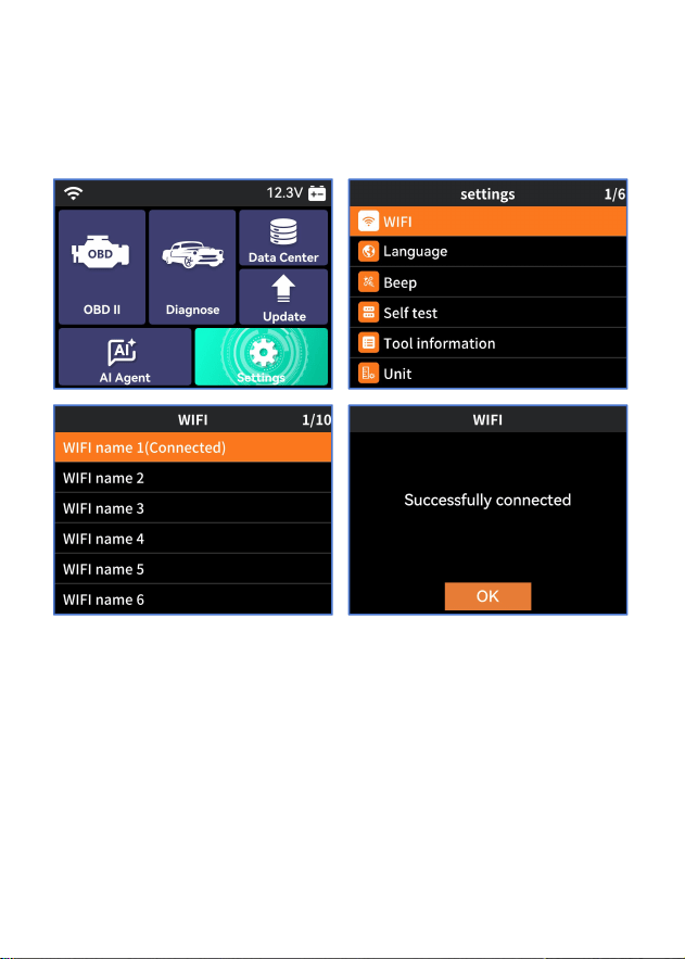
6.1.9. Mode 8
This feature can detect leaks in the vehicle's fuel evaporation system and
requires the vehicle to support this detection capability.
6.2. Fault Code Query
In the Fault Code Query option, users can use the direction keys to select
the desired fault code and press the "OK" key to view its definition.
11
6.3. Diagnose
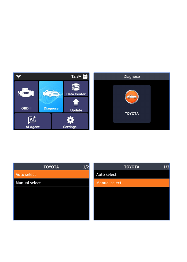
(1)On first use, ensure the diagnostic device is connected to Wi-Fi, then
go to the "Settings" menu and select "Wi-Fi".
12
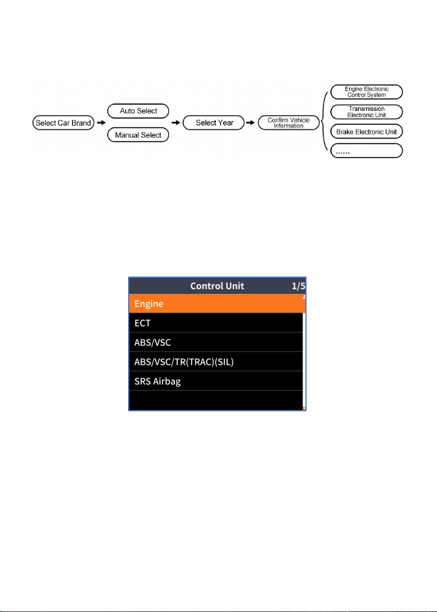
(2)Select the "Diagnostic" function, add the car brand you need to
diagnose, and follow the steps below.
Note: The product comes without a vehicle model system. When using it for
the first time, download the vehicle model yourself. For subsequent model
selections, the product can manually or automatically erase or overwrite
previous model data.
(3)You can start the diagnosis after adding it.
13
(4)Follow these steps to log in to the system:
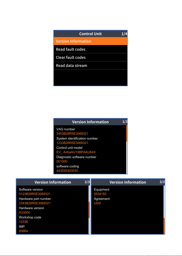
(5)Upon entering the control unit menu, the diagnostic tool displays all
detectable systems that can be diagnosed. You may select the system
requiring diagnosis to proceed.
14
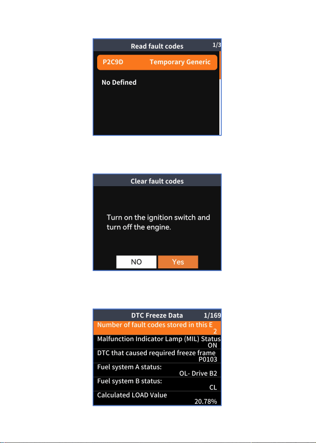
(6)If you select "Airbag," version information, code reading, code
clearing, and data flow will be displayed.
Version Information
15
Read the fault code
Clear the fault code
Data flow
16
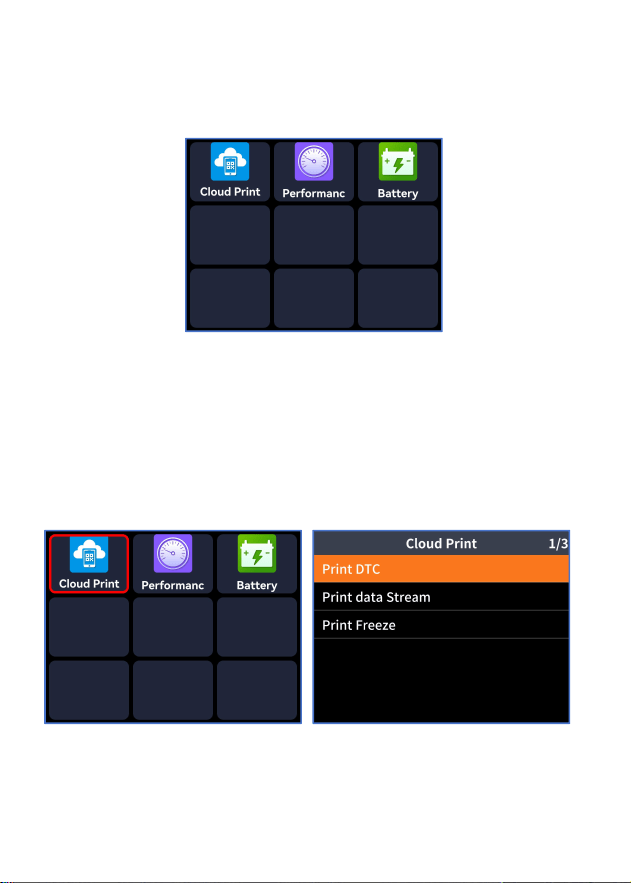
6.4. Data Center
It covers cloud printing, performance testing, and battery monitoring.
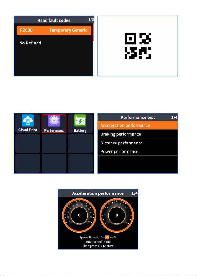
6.4.1. Cloud Printing
The read fault codes, data streams, frozen frames, and other data can be
converted into QR codes, which can be scanned, shared, or printed via a
smartphone.
17
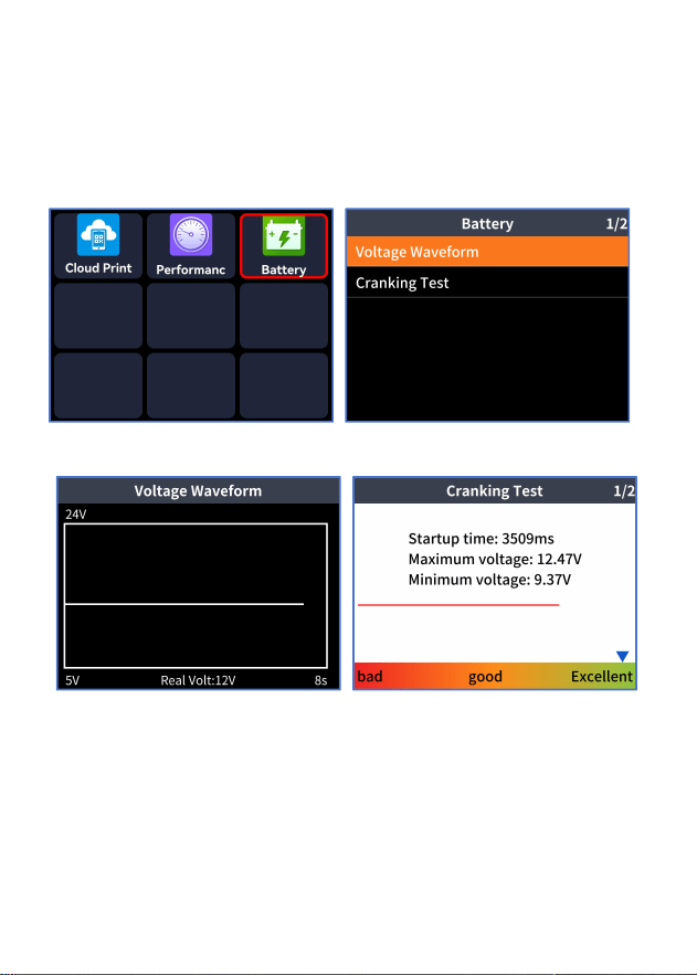
6.4.2. Performance Testing
Test the vehicle's acceleration performance, braking performance, distance
tests, and instrument data.
18
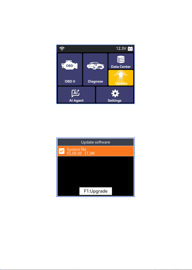
6.4.3. Battery Testing
It can measure both the battery voltage and instantaneous voltage of a
vehicle.
19
6.5. Upgrade
After connecting the product to Wi-Fi, you can upgrade it.
Select the upgrade project and wait for it to complete.
20
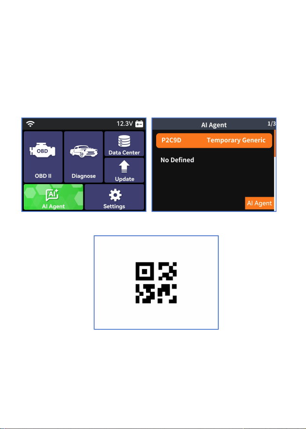
6.6. AI Agent
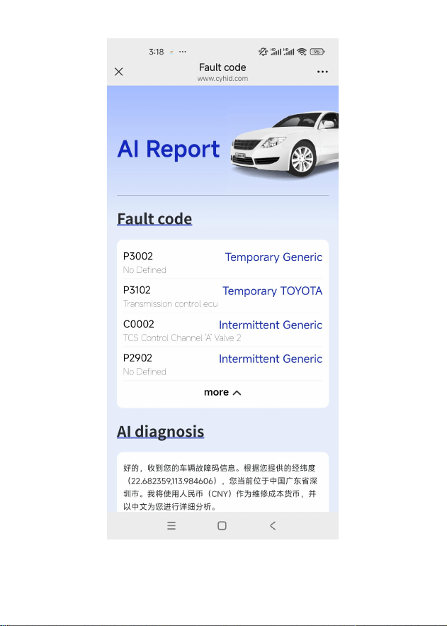
The AI agent can diagnose fault codes and generate detailed analysis
reports.
If the "AI Agent" background is highlighted, press the "OK" key to enter,
scan the QR code, and view the AI report.
21
22
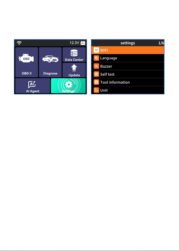
6.7. Set Up
Go to the settings options to configure various product parameters, such as
language and units.
7. Exemption Conditions
We are committed to providing unparalleled customer support before and
after sales, and the following are our disclaimer conditions for our products:
If any of the following conditions are met, customers shall not be entitled to
policies within the scope of this limited warranty:
1) Abnormal use, abnormal situations, improper storage, exposure to
moisture or unauthorized modification, misuse, negligence, abuse,
accidents, changes, improper installation, or other non fault behaviors of
the product, including damage caused by transportation.
2) Our company is not responsible for any damage to the product caused
by external reasons (such as collision with objects), fire, flood, sand, dust,
storm, lightning, earthquake or weather conditions, uncontrollable acts
of natural disasters, battery leakage, theft, blown fuses, improper use of
any power source, etc.

23
Warning Statement
This device complies with part 15 of the FCC Rules. Operation is subject to the
following two conditions: (1) This device may not cause harmful interference, and (2)
this device must accept any interference received, including interference that may cause
undesired operation.
Any Changes or modifications not expressly approved by the party responsible for
compliance could void the user's authority to operate the equipment.
Note: This equipment has been tested and found to comply with the limits for a Class B
digital device, pursuant to part 15 of the FCC Rules. These limits are designed to
provide reasonable protection against harmful interference in a residential installation.
This equipment generates uses and can radiate radio frequency energy and, if not
installed and used in accordance with the instructions, may cause harmful interference
to radio communications. However, there is no guarantee that interference will not
occur in a particular installation. If this equipment does cause harmful interference to
radio or television reception, which can be determined by turning the equipment off and
on, the user is encouraged to try to correct the interference by one or more of the
following measures:
-Reorient or relocate the receiving antenna.
-Increase the separation between the equipment and receiver.
-Connect the equipment into an outlet on a circuit different from that to which the
receiver is connected.
-Consult the dealer or an experienced radio/TV technician for help.
This equipment complies with FCC radiation exposure limits set forth for an
uncontrolled environment. This equipment should be installed and operated with
minimum distance 20cm between the radiator & your body.