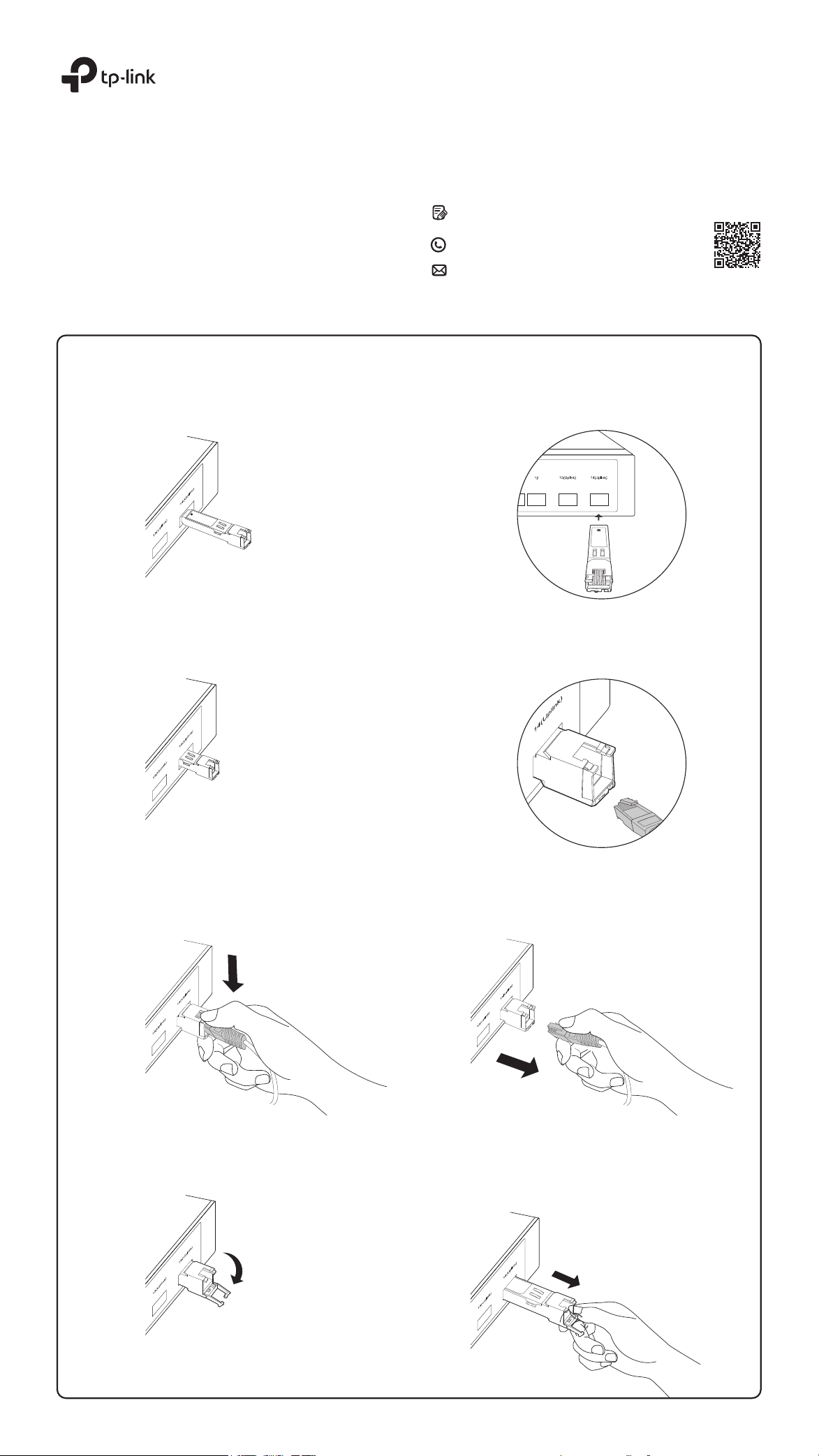
Installing the RJ45 SFP / RJ45 SFP+ Module
RJ45 SFP / RJ45 SFP+ Module
1. Lock the yellow latch into place and insert the module into an SFP / SFP+ slot with label side up.
2. Gently push the module into the slot until you hear a click. Then, insert the RJ45 network cable.
Installation Guide
©2022 TP-Link 7106509485 REV1.1.0
For technical support and other information, please visit
https://www.tp-link.com/support, or simply scan the QR code.
If you have any suggestions or needs on the product guides,
welcome to email techwriter@tp-link.com.cn.
To ask questions, find answers, and communicate with TP-Link
users or engineers, please visit https://community.tp-link.com
to join TP-Link Community.
Removing the RJ45 SFP / RJ45 SFP+ Module
1. Press the RJ45 crystal head and pull out the cable.
2. Pull down the latch and remove the module.
Note: Images may dier from the actual products.
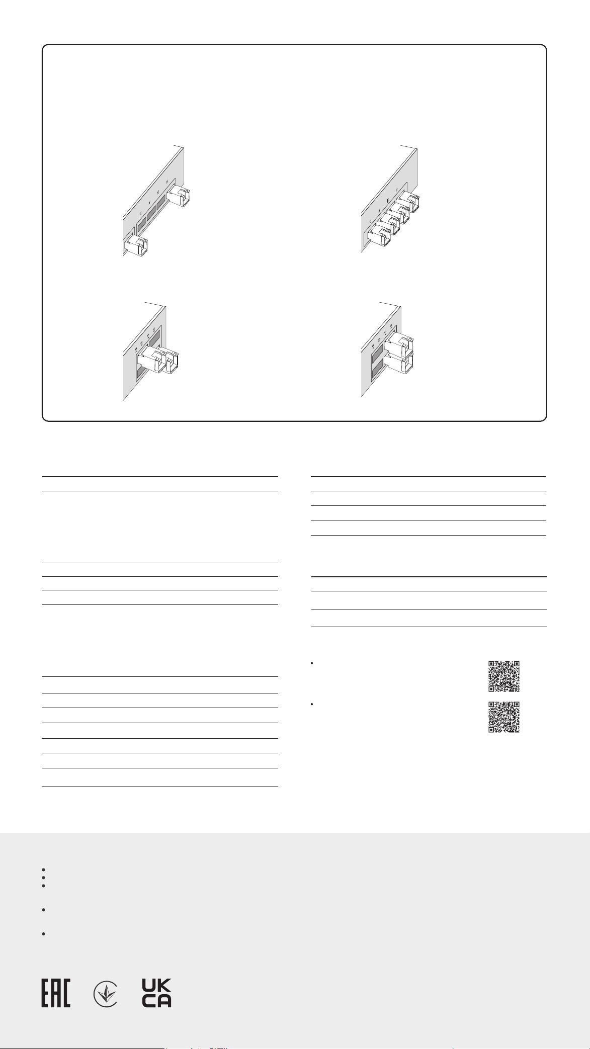
The 10G RJ45 SFP+ modules consume more power than optical modules. This may result in higher heat. To avoid overheating, it is recommended to place the
modules separated by multiple optical transceivers or empty slots.
When used in high temperature environments, additional cooling must be applied.
Positioning the 10G RJ45 SFP+ Modules
Specications
Compatiblity
We recommend that you use only TP-Link modules on your TP-Link devices.
TL-SM331T:
https://www.tp-link.com/tl-sm331t/product-list/
TL-SM5310-T:
https://www.tp-link.com/tl-sm5310-t/product-list/
Note:
1. TL-SM331T does not support the data rate of 10 Mbps or 100 Mbps.TL-SM
5310-T does not support the data rate of 10 Mbps, but supports 100 Mbps /
1 Gbps / 2.5 Gbps / 5 Gbps / 10 Gbps.
2. When a Gigabit RJ45 SFP module is inserted into a 10 Gbps SFP+ slot, extra
conguration may be required.
3. When the 10G RJ45 SFP+ module is inserted into a 10 Gbps SFP+ slot and
the maximum rate of the peer connection port is 5 Gbps, 2.5 Gbps, 1 Gbps,
or 100 Mbps, the ow control for the 10 Gbps SFP+ slot needs to be
manually enabled.
To check the compatible TP-Link devices of your module, please visit our
website:
Product Operating Temperature 0˚C to 70˚C (32˚F to 158˚F)
Storage Temperature -40˚C to 85˚C (-40˚F to 185˚F)
Storage Humidity 5% to 90% RH, Non-condensing
Operating Humidity 10% to 90% RH, Non-condensing
Environmental and Physical Specications
Safety Information
Keep the device away from water, re, humidity or hot environments.
Do not touch the device while it is operating.
To prevent potential risks caused by heat, do not place your network device on
non-heat-resistant paper, cloth, fabrics, plastics, or any other surface that
doesn't provide space beneath your device for heat dissipation.
The air ow around the device should be increased, or the overall ambient
temperature should be lowered to keep the temperature of the modules within
the recommended range.
Do not attempt to disassemble, repair, or modify the device. If you need
service, please contact us.
TP-Link hereby declares that the device is in compliance with the essential
requirements and other relevant provisions of directives 2014/30/EU,
2014/35/EU, 2009/125/EC, 2011/65/EU and (EU)2015/863.
The original EU declaration of conformity may be found at
https://www.tp-link.com/en/support/ce.
EU Declaration of Conformity
UK Declaration of Conformity
Scenario 1:
Not RecommendedRecommended
Scenario 2:
Recommended Not Recommended
General Specications
RX_LOS
MAC Interface
Power Consumption (max.) 0.8 W 2.5 W
/
/
Ye s
Standards and Protocols
Normal
Data Rate1 (max.)
TX_Fault
TX_Disable
Ye s
/
Hot Swappable
LLF
/
LFP
1000BASE-X
1.25 Gbps
TL-SM331T
1000BASE-T: UTP
cat.5e or above
(max. 100m)
TL-SM5310-T
XFI
10.3125 Gbps
100BASE-TX: UTP cat.5
or above (max. 100m)
1000BASE-T/2.5GBASE-T/
5GBASE-T: UTP cat.5e or
above (max. 100m)
10GBASE-T: UTP cat.6a or
above (max. 30m)
Cable Distance
/
DDM
/
/
Ye s
Ye s
/
/
Yes
(temperature and voltage)
IEEE 802.3
IEEEE 802.3ab
SFF-8472
IEEE 802.3
IEEE 802.3u
IEEEE 802.3ab
IEEE 802.3bz
IEEE 802.3an
SFF-8472
SFF-8431
Normal
SupportedGigabit SFP Slot (SFP Slot)
TL-SM331T
TL-SM5310-T
Supported210G SFP+ Slot (SFP+ Slot)
/
Supported3
TP-Link hereby declares that the device is in compliance with the essential
requirements and other relevant provisions of the Electromagnetic Compatibility
Regulations 2016 and Electrical Equipment (Safety) Regulations 2016.
The original UK Declaration of Conformity may be found at
https://www.tp-link.com/support/ukca
The gures below only show the recommended positioning. The actual number of modules that can be inserted depends on the switch's heat dissipation and
power margin.