SAFETY PRECAUTIONS
Set-up Options for Connecting Your Bluetooth Downlight
App Download:
Notes:
Please press icon on the APP to save the setting after you
Scan the QR code to download the App, follow instructions for direct to phone set-up, this Bluetooth device is compatible with
the Lighting control system only.
LED Bluetooth Retrofit Troffer Installation Guide
Please do not set the speed (S) less than 0.3 for the "Daylight Harvesting"
Please do not turn on the sensor function if the downlight does not have
change the "Sensor Settings"
Speed (S) 0.3
Commissioning:
The mobile App is the easiest way to pair devices,
create groups, set scenes, set schedules, dimming,
color tuning, and adjust high trim based on needs.
this design.
Please reset the Bluetooth function or unbind the fixture from the control terminal before you install the fixture.
1
CAUTION-Connect the fixture to a 120/277V, 50/60Hz power source. Any other connection voids the warranty.
WARNING-To prevent wiring damage or abrasion, do not expose wiring to edges of sheet metal or other sharp objects.
WARNING -Wear gloves when handling the fixture as edges are sharp.
Do not make or alter any open holes in an enclosure of wiring or electrical components during kit installation.
Only those open holes indicated in the photographs and/or drawings may be made or altered as a result of kit installation.
Examine all parts that are not intended to be replaced by the retrofit kit for damage and replace any damaged parts prior to
installation.
This device is not intended for use with emergency exits.
This luminaire is suitable for Damp locations. Prior to installation,review all environmental designation locations in the product
specsheet. Only install in damp locations if so indicated in the spec sheet.
Suitable for open type luminaires.
For dimming or lighting controls, use provided wiring diagram only.
This luminaire must be installed in accordance with the NEC or your local electrical code.If you are not familiar with these
codes and requirements, consult a qualified electrician.
Before installation or servicing, turn the power OFF at the circuit breaker or fuse. Place tape over the circuit breaker switch
and verify power is OFF at the light fixture.
Ground the fixture to avoid potential electric shock.
Do not handle an energized module with wet hands or when standing on wet or damp surfaces, or in water.
Luminaire wiring and electrical parts may be damaged when drilling for installation of the LED retrofit kit. Check for enclosed
wiring and components.
This product must be installed in accordance with the applicable installation code by a person familiar with the construction
and operation of the product and the hazards involved.
Install this kit only in luminaires that have the construction features and dimensions shown in the photographs and/or
drawings and where the input rating of the retrofit kit does not exceed the input rating of the luminaire.
Input ratings may need to be determined based on any configuration(s) permitted by the installation instructions, Regardless
of the configuration(s) of the retrofit kit, the input ratings of the overall retrofit kit shall not exceed the marked input ratings of
the host luminaire.
The Retrofit Kit is accepted as a component of a luminaire where the suitability of the combination shall be determined by
authorities having jurisdiction. Product must be installed by a qualified electrician in accordance with the applicable and
appropriate electrical codes, this installation guide does not supersede local or national regulations for electrical installation.
Do not leave anyother open holes in an enclosure of wiring or electrical components.
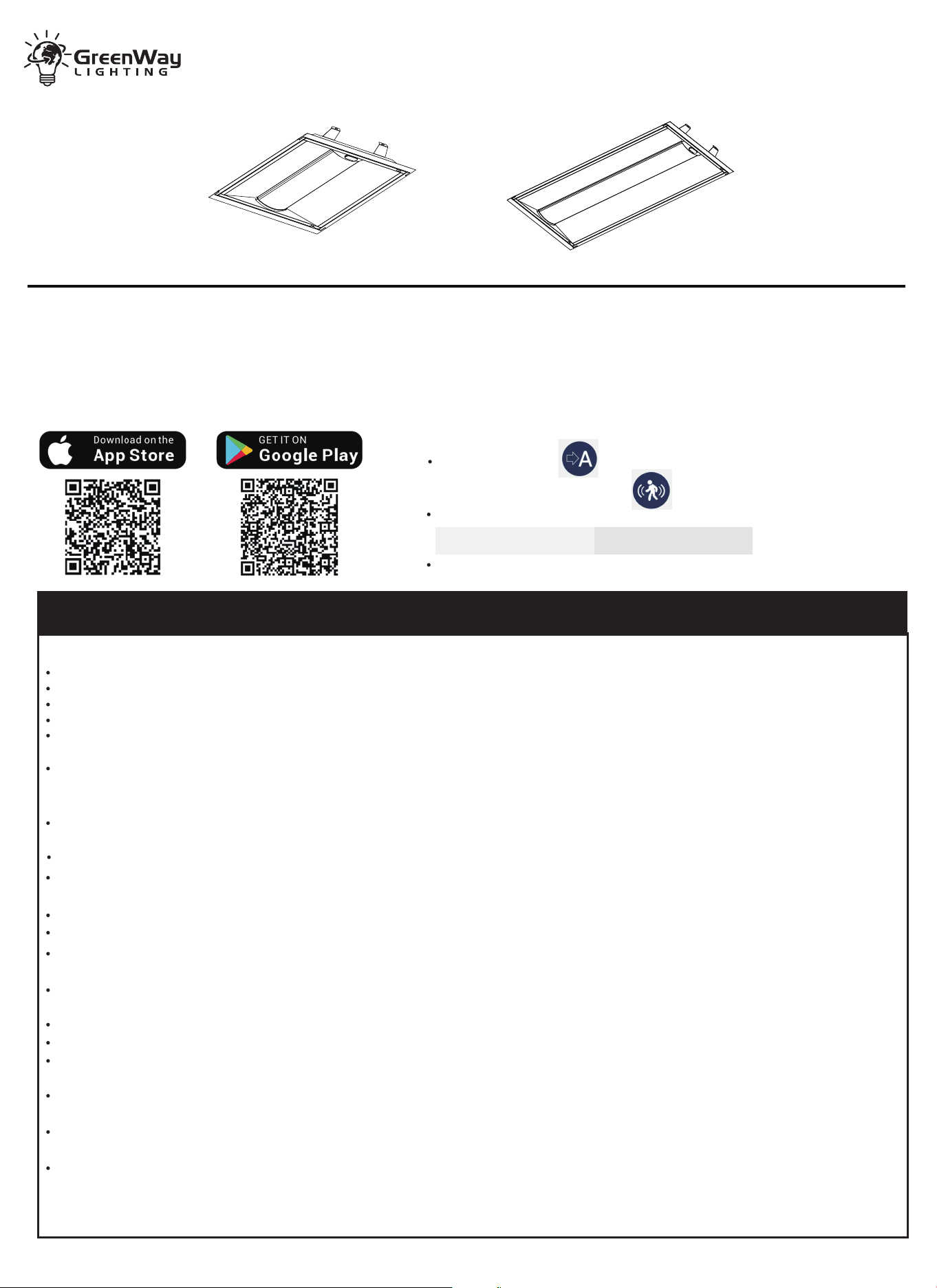
2X2FT
2X4FT
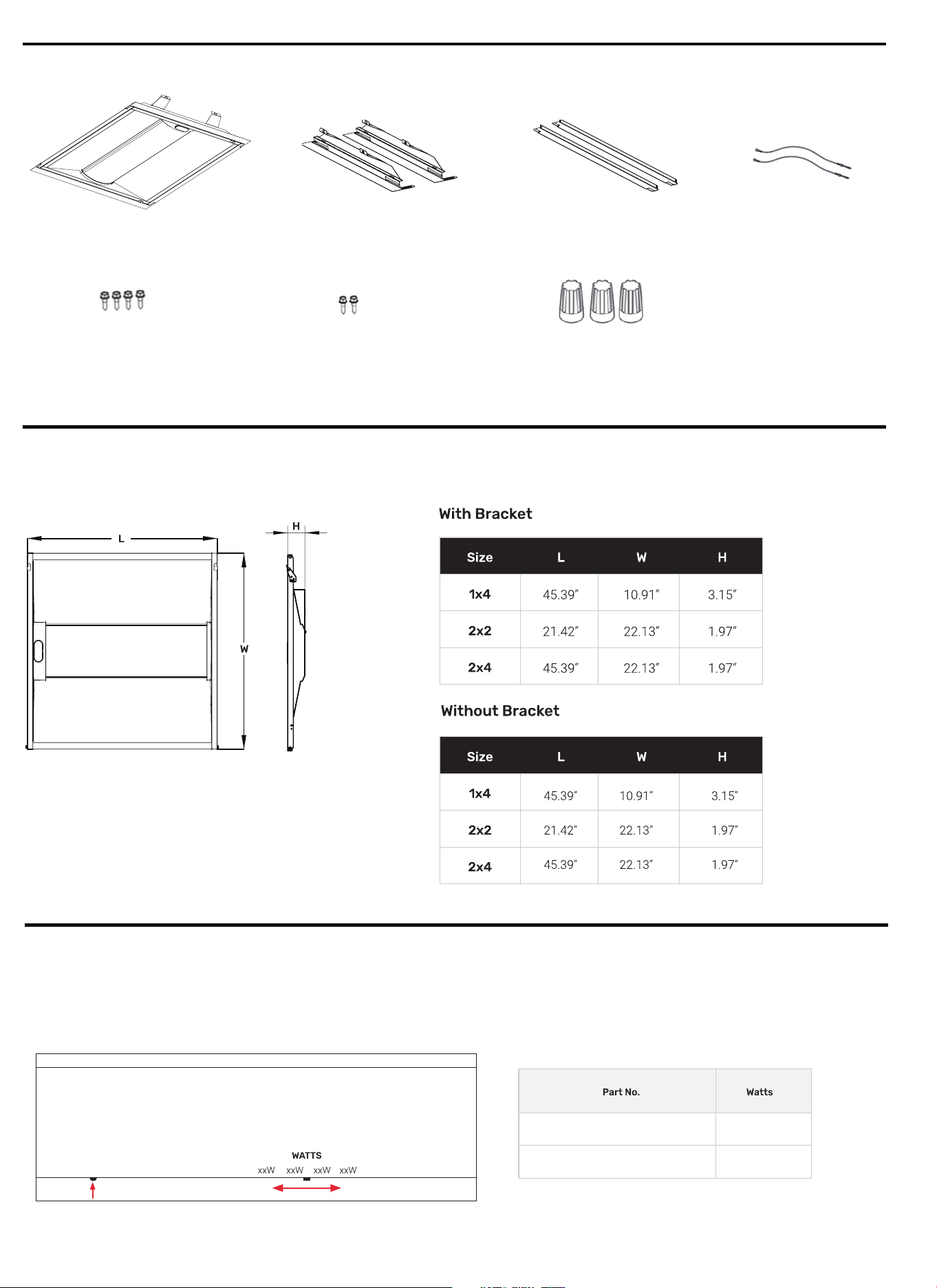
DIMENSIONAL DRAWING
2
SUPPLED COMPONENTS
POWER SELECT (WATTAGE) ADJUSTMENT
This fixture is equipped with field-adjustable Power Select.
1. Ensure power is off to the fixture.
2. Adjust dip switches to desired settings.
2x Safety Cables
1x Door Kit Fixture
2x Assembly Brackets
2x Trim Brackets
4x Self-Tapping Screws
2x Self-Tapping M4 Screws
3x Wire Nuts
Reset Button
GW-RFKT22-30WS-CCT-BLE-BS
GW-RFKT24-35WS-CCT-BLE-BS
15/20/25/30W
20/25/30/35W
INSTALL INSTRUCTIONS
REMOVAL OF EXISTING LIGHT ENGINE
INSTALLATION OF RETROFIT KIT
Step 1.
Disconnect power to the host lighting fixture to be replaced.
Step 1.
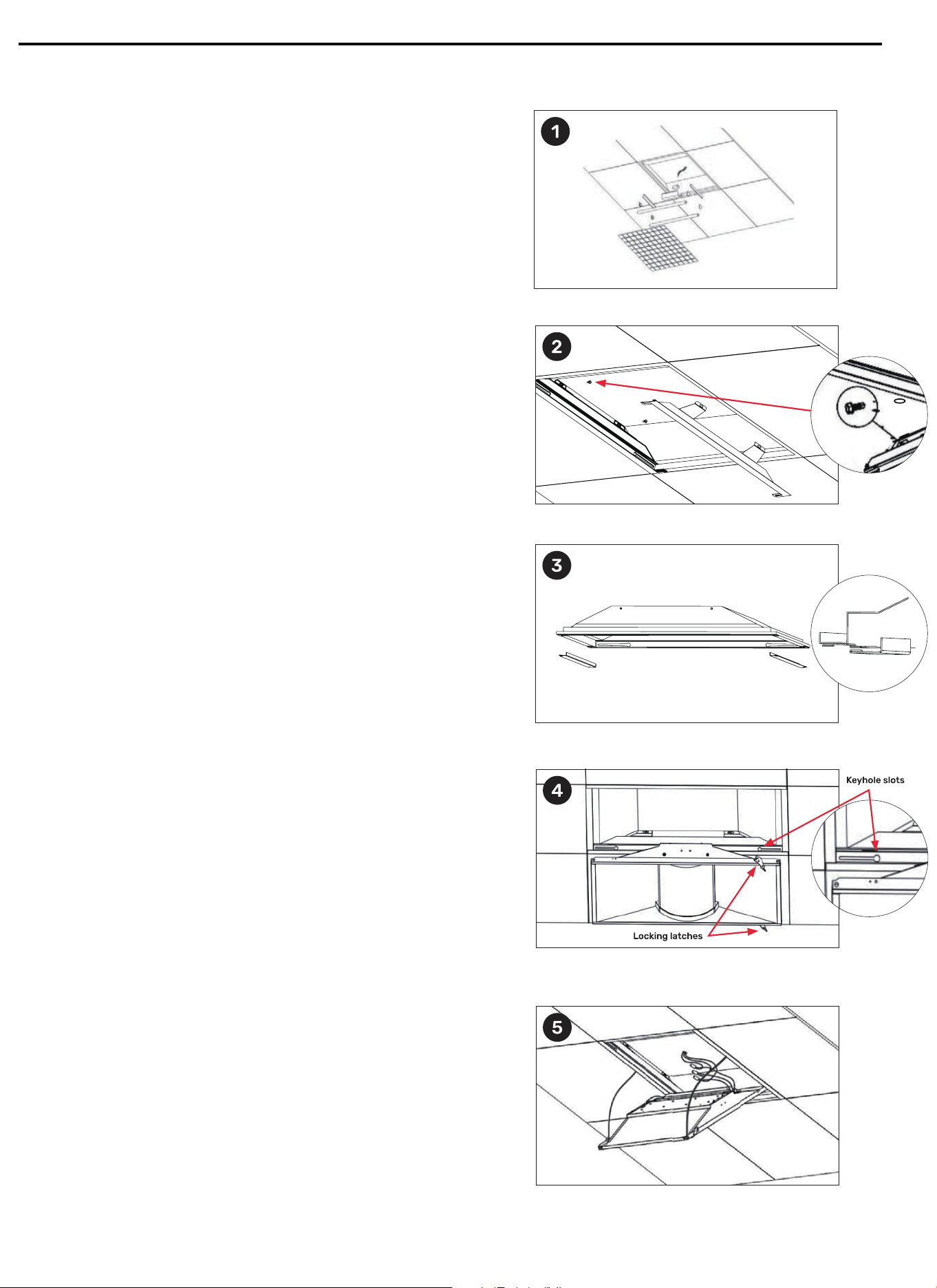
Install the assembly brackets to fit in the existing fixture by using the
(4) #8 1/2 screw. Make sure to secure the assembly bracket flat on the grid.
See Figure 2.
Step 2. If there is a gap between the fixture and T-grid, add optional trim brackets.
Push up existing troffer housing and slide the trim brackets into place
between existing fixture and T-grid. See Figure 3.
Step 3. Place the door assembly body onto the keyholes of the end brackets and
slide it horizontally to the end of the slots. See Figure 4.
Step 4. Attach (2) safety cables to existing troffer housing using washer head M4
screws provided in hardware bag. See Figure 5.
Step 5. Wire fixture per the provided Wiring Diagram in this manual and tuck all
leads into the back of the existing fixture housing. Ensure that no leads
are pinched. See Figure 5.
Step 6. Secure the door assembly by gently swinging the door up into the other
side of the fixture and then locking in place with the locking latches riveted
on each end of the assembly door frame. See Figure 4.
Step 2. Remove the Lens/Louver, Fluorescent Lamps, Lamp Holders (if applicable) ,
Lamp Holder Leads and Ballast Cover from existing fixture. See Figure 1.
Step 3.
Cut the power wires going into the input side of the ballast. The ballast
may remain in place, unless it is determined that it needs to be removed to
provide extra clearance. NOTE: lf parts have to be removed from the host
lighting fixture in order to complete the installation of this upgrade kit, then
make sure that open holes are closed-off utilizing the existing host lighting
fixture hardware (i.e screws, covers, etc.)
4
WIRING DIAGRAM
CAUTION
INSTALLATION OF RETROFIT KIT
Step 1.
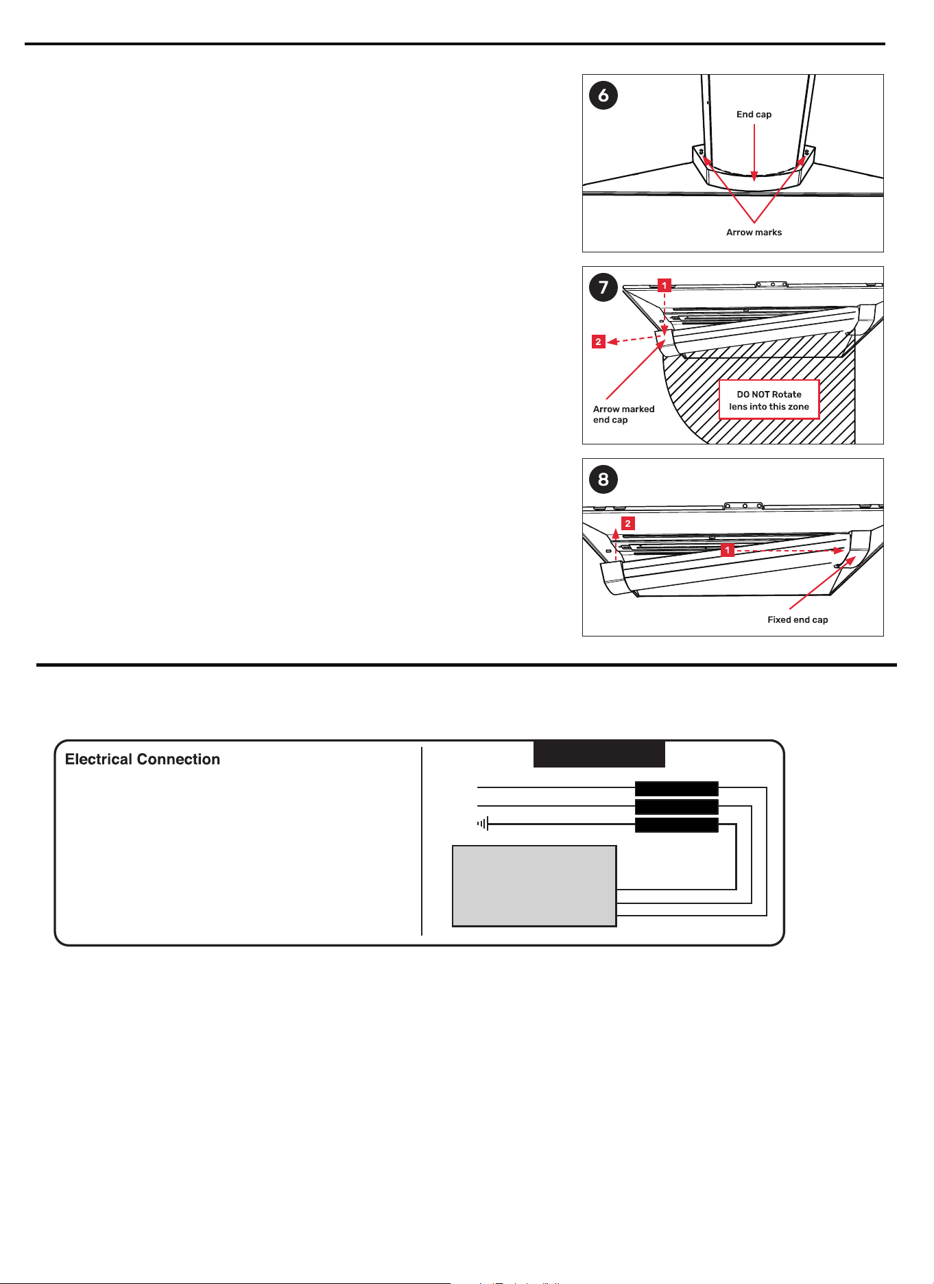
Locate the end cap with the arrow marks on it, indicating that the end cap is
removable. See Figure 6.
Step 2. Squeeze the middle of the lens while grabbing the lens section next to the
end cap and pull lens and end cap together downward gently until end cap
just clears luminaire (about 3" to 4" from original position). See Figure 7.
Step 3. Disengage the other end of the lens from the other end cap. Once lens is
removed, perform cleaning. See Figure 7.
Step 4. After cleaning is complete, insert lens back into fixed end cap. Push the removable
end cap upward into the housing and using a gentle rocking motion engage the end
cap to retention clip. Check removable end cap for any visible gap between the end
cap and end panel. lf necessary push end cap against the end panel to eliminate
gaps. In 1'X 4' and 2'X 4' products make sure lens is snapped under lens retention
clips in middle of housing.See Figure 8.
CAUTION: Turn off electrical power at fuse or circuit breaker box before wiring fixture to the power supply.
Wiring Diagram
LED DRIVER
Connect BLACK (line) driver lead to voltage supply Line
position (HOT).
Connect driver WHITE lead to the NEUTRAL supply
position.
Connect the GREEN ground lead to the supply ground
lead.
Connector
Connector
Connector
Black (Line)
White (Neutral)
Green (Ground)
• This device complies with Part 15 of the FCC Rules. Operation is subject to the following two conditions:
(1) this device may not cause harmful interference, and (2) this device must accept any interference received, including interference
that may cause undesired operation.
These limits are designed to provide reasonable protection against harmful interference in a residential installation. This equipment
generates, uses and can radiate radio frequency energy and, if not installed and used in accordance with the instructions, may cause
harmful interference to radio communications. However, there is no guarantee that interference will not occur in a particular installation.
If this equipment does cause harmful interference to radio or television reception,which can be determined by turning the equipment off
and on,the user is encouraged totry to correct the interference by one or more of the following measures:
—Reorient or relocate the receiving antenna.
—Increase the separation between the equipment and receiver.
—Connect the equipment into an outlet on a circuit different from that to which the receiver is connected.
—Consult the dealer or an experienced radio/TV technician for help.
The distance between user and products should be no less than 20cm.
Changes or modifications not expressly approved by the party responsible for compliance could void your authority to operate the equipment.
•