
Copyright©
Shenzhen Minewsemi Co., Ltd.
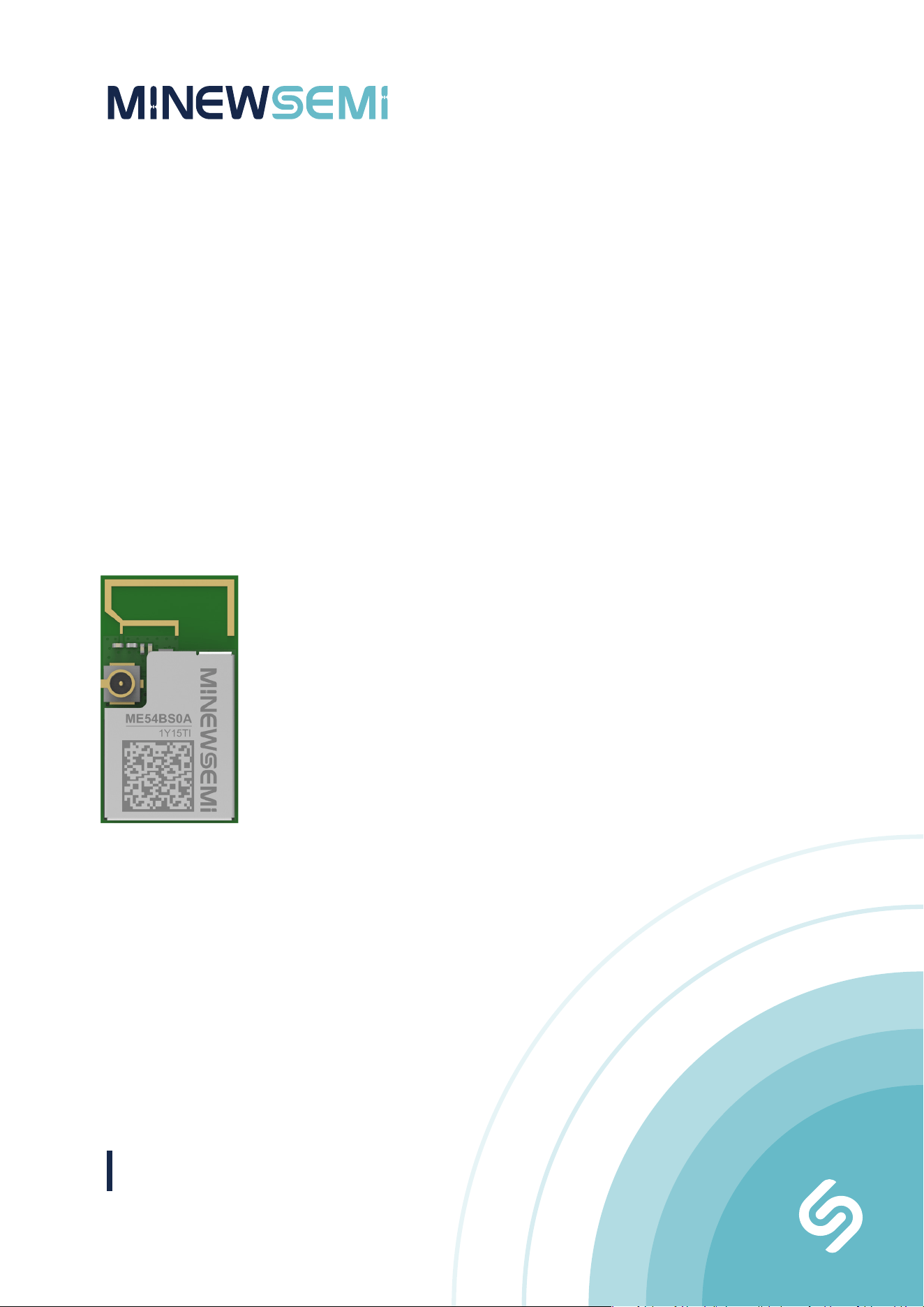
Bluetooth LE Module
V 1.1.0
ME54BS0A
Datasheet

02
ME54BS0A
Datasheet
Version Note
Version Details Contributor(s) Date Notes
1.0.0 First edit Michelle 2026.04.10
@
Part Number
Model Hardware Code
Click the icon to view and download the latest product documents electronically.
ME54BS0A
1Y15TI
https://en.minewsemi.com/file/ME54BS0A-nRF54L15_Datasheet_M_EN.pdf
1.1.0 Updated PCB Design Michelle 2026.05.13
ME54BS0A
The ME54BS0A is a master-slave module that can switch between master and slave modes via commands. The master and
slave modes cannot operate simultaneously, and only one-to-one connections are supported. The device defaults to master
mode.
In master mode, the module can scan for and connect to devices via commands. Scanning supports filtering by advertising
name and MAC address to identify target devices. Connections can be initiated by specifying a MAC address.
The module communicates with an MCU through a UART interface. In command mode, the MCU can send UART commands
to configure parameters such as scan interval, scan timeout, connection interval, advertising interval, custom advertising
data, and baud rate.
The MCU can also send a command via UART to switch the module to slave mode. In slave mode, the module supports both
advertising and connection states, allowing it to be connected by a master device. It acts as a bridge between the master
device and the MCU, enabling transparent data transmission.
High Sensitivity, PCB/U.FL Optional, Multi-protocol Bluetooth 6.0 PA Module
Web:www.minewsemi.com Tel:0086 755-2801 0353 E-mail:minewsemi@minew.com Copyright© Shenzhen Minewsemi Co., Ltd.
APPLICATION
FEATURES
KEY PARAMETERS
Chip Model
Module Size
Flash
Receiving Sensitivity
Emission Current
Firmware
nRF54L15
18×10×1.7mm
1524KB NVM
-96dBm
20dBm-150mA
Master-slave firmware
Antenna
GPIO
RAM
Transmitting Power
Receiving Current
Transmission Distance
PCB/U.FL (MHF 1)
30
256KB
+20dBm
7mA
800m
ME54BS0A
03
ME54BS0A
Datasheet
CERTIFICATION
Bluetooth 6.0 Maximum transmission
speed up to 11kB/s
Supports serial
command configuration
Built-in PA/LNA Supporting iBeacon
broadcast mode
Smart
Home
Computer
Accessories
Game controllers
and Remotes
Medical Devices Industrial IoT
Virtual reality and
Augmented reality
Support OTA
OTA
3.Current Consumption Characteristics
12.FCC warning
14.Handling Conditions
INDEX
1.Block Diagram
05
05
06
06
07
08
08
08
09
09
09
09
09
09
09
17
17
18
18
19
20
22
23
23
24
26
27
28
31
31
32
32
10
13.Storage Conditions
31
2.Electrical Specification
4.Pin Description
5.Pin Definition
8.Electrical Schematic
9.PCB Design
6 Module Operation Instructions
6.1 Tool
6.2 Wiring
6.2.1 Power Supply
6.2.2 SLP(Sleep/Wake)
6.2.3 BTDATA(UART Control)
6.2.4 UART interface:TX and RX
6.2.5 CON_IND
6.2.6 FIFO_FULL
6.2.7 Operating Mode
6.2.8 Command Instructions
6.3 Operation Examples
6.3.1 Factory Default Parameters
6.3.2 Parameter Modification Example
6.3.3 Scanning and Connecting to Devices
6.3.4 Transparent Transmission Test Procedure
6.3.5 Slave Broadcasting
6.3.6 Slave Pass-Through
10.Reflow and Soldering
11.Package Information
16.Copyright Statement
17.Related Documents
15.Quality
Web:www.minewsemi.com Tel:0086 755-2801 0353 E-mail:minewsemi@minew.com Copyright© Shenzhen Minewsemi Co., Ltd.
04
ME54BS0A
Datasheet
7.Mechanical Drawing
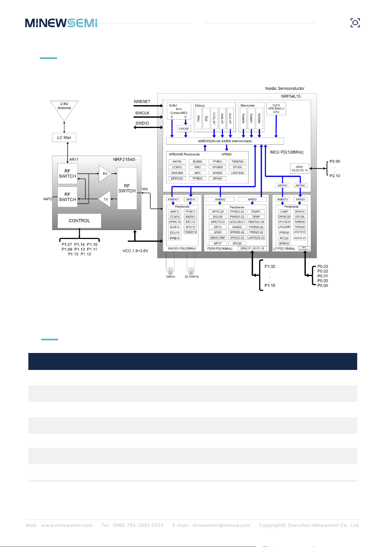
BLOCK DIAGRAM
1
2
ELECTRICAL SPECIFICATION
Working Voltage
Working Temperature
Transmission Power
Receiving Current
Emission Current
Module Dimensions
Quantity of IO Port
Operating temperature from -40°C to 85°C
Cannot be set
RF receiving current under 1Mbps pattern
RF transmission current under 20dBm pattern
1.9V-3.6V
-30℃~+80℃
~ +20dBm
7mA
150mA
18x10x1.7mm
30
Parameters Value Notes
Web:www.minewsemi.com Tel:0086 755-2801 0353 E-mail:minewsemi@minew.com Copyright© Shenzhen Minewsemi Co., Ltd.
05
ME54BS0A
Datasheet
To ensure RF work, it is recommended that
the supply voltage should not be lower than 2.3V.
The following power consumption tests were conducted at a supply voltage of 3.3V and at room temperature. Power
consumption differs between master and slave modes.
In slave mode, power consumption is as follows: (broadcast interval is 1 s, connection interval is 20 ms, transmission power
is 20 dBm).
In master mode, power consumption is as follows: (connection interval: 20 ms; transmission power: 20 dBm)
4
PIN DESCRIPTION
3
CURRENT CONSUMPTION CHARACTERISTICS
2.64mA
149.60mA
139.41mA
204.25mA
202.80mA
204.60mA
7.34μA
289.96μA
427.64μA
9.35mA
1.14mA
3.03mA
Sleep mode average current
(SLP pulled high, BTDATA pulled high)
Broadcast average current (SLP and BTDATA
pin connected to GND)
Broadcast average current (SLP pin connect-
ed to GND, BTDATA pulled high)
Transmission average current (SLP, BTDATA pin pulled low, baud rate
115200,200 bytes, 20ms/time)
Broadcast average current in Longrange operating mode (SLP pulled
low, BTDATA pin pulled high)
Longrange operating mode connection state average current
(connected to VDD, GND, SLP pulled low, BTDATA pin pulled high)
Status
Consumption
Peak Avg
Web:www.minewsemi.com Tel:0086 755-2801 0353 E-mail:minewsemi@minew.com Copyright© Shenzhen Minewsemi Co., Ltd.
06
ME54BS0A
Datasheet
8.20mA
4.16mA
32.32mA
120.63mA
113.71mA
201.74mA
Average current during scanning (with all pins connected)
Send the command "TTM:SCT-0" to successfully set the module
into a continuous (infinite) scanning mode
Transparent average current
(SLP, BTDATA pin pulled low)
Average current in pass-through mode in Long-range mode
(SLP, BTDATA pin pulled low)
Status
Consumption
Peak Avg
5
PIN DEFINITION
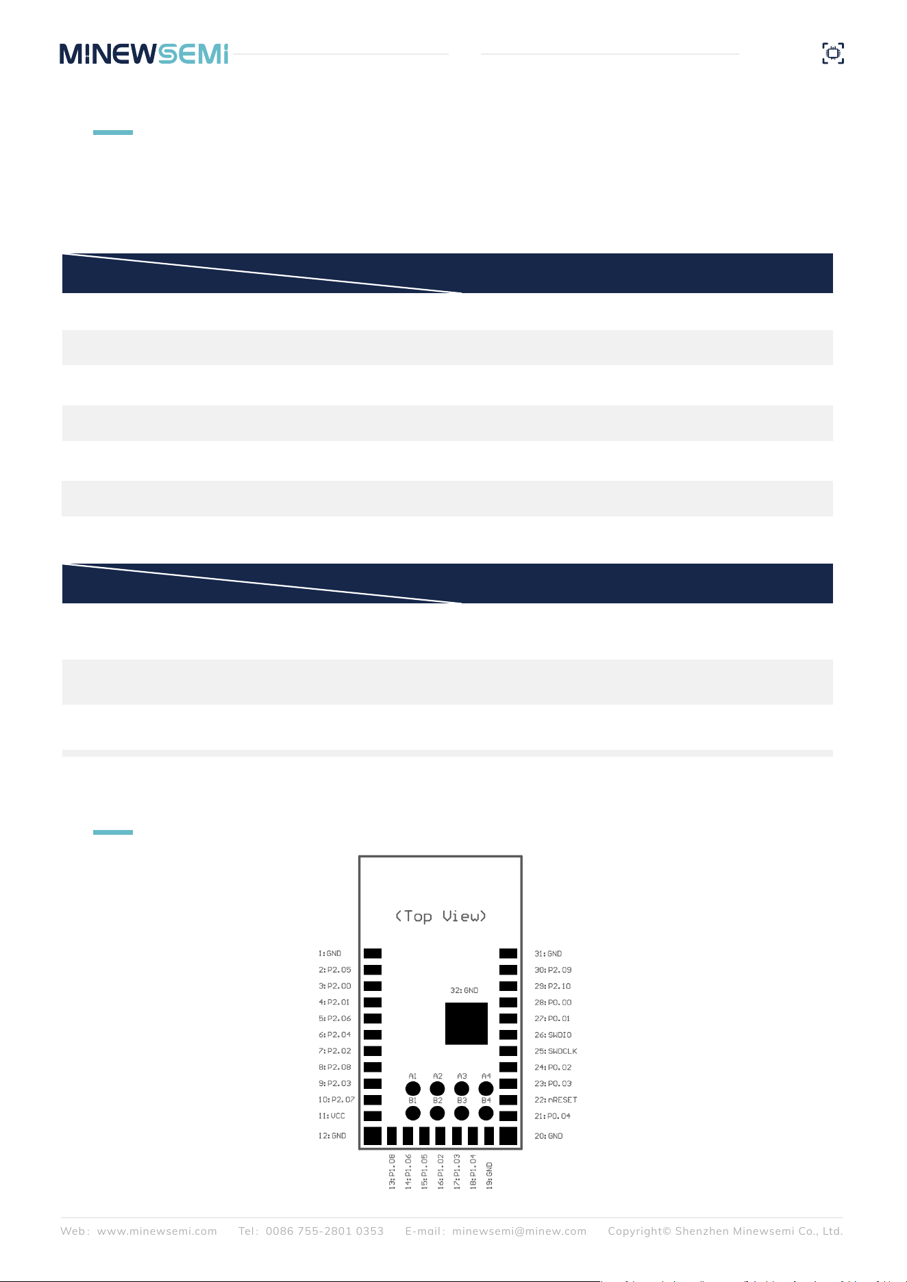
Pin Number Symbol Type Definition
Web:www.minewsemi.com Tel:0086 755-2801 0353 E-mail:minewsemi@minew.com Copyright© Shenzhen Minewsemi Co., Ltd.
07
ME54BS0A
Datasheet
1
2
3
4
5
6
7
8
9
10
11
12
13
14
15
16
17
18
19
20
21
22
23
24
25
26
GND
P2.05
P2.00
P2.01
P2.06
P2.04
P2.02
P2.08
P2.03
P2.07
VCC
GND
P1.08
P1.06
P1.05
P1.02
P1.03
P1.04
GND
GND
P0.04
NRESET
P0.03
P0.02
SWCLK
SWDIO
GND
GPIO
GPIO
GPIO/CK
GPIO/CK
GPIO
GPIO
GPIO
GPIO
GPIO/SWO
VCC
GND
GPIO
TX
RX
GPIO/NFC1
GPIO/NFC2/CK
GPIO/AIN0/CK
GND
GND
GPIO/CK
Reset
BTDATA
SLP
Programming clock pin
Programming data pin
General-purpose I/O port
General-purpose I/O port
General-purpose I/O port
General-purpose I/O port
General-purpose I/O port
General-purpose I/O port
General-purpose I/O port
General-purpose I/O port
General-purpose I/O port
General-purpose I/O port
Bluetooth TX
Bluetooth RX
General-purpose I/O port
General-purpose I/O port
General-purpose I/O port
General-purpose I/O port
Low-level reset, high-level operation
High level: Disable UART Low level: Enable UART
High level: Sleep Low level: Wake
For firmware programming
For firmware programming
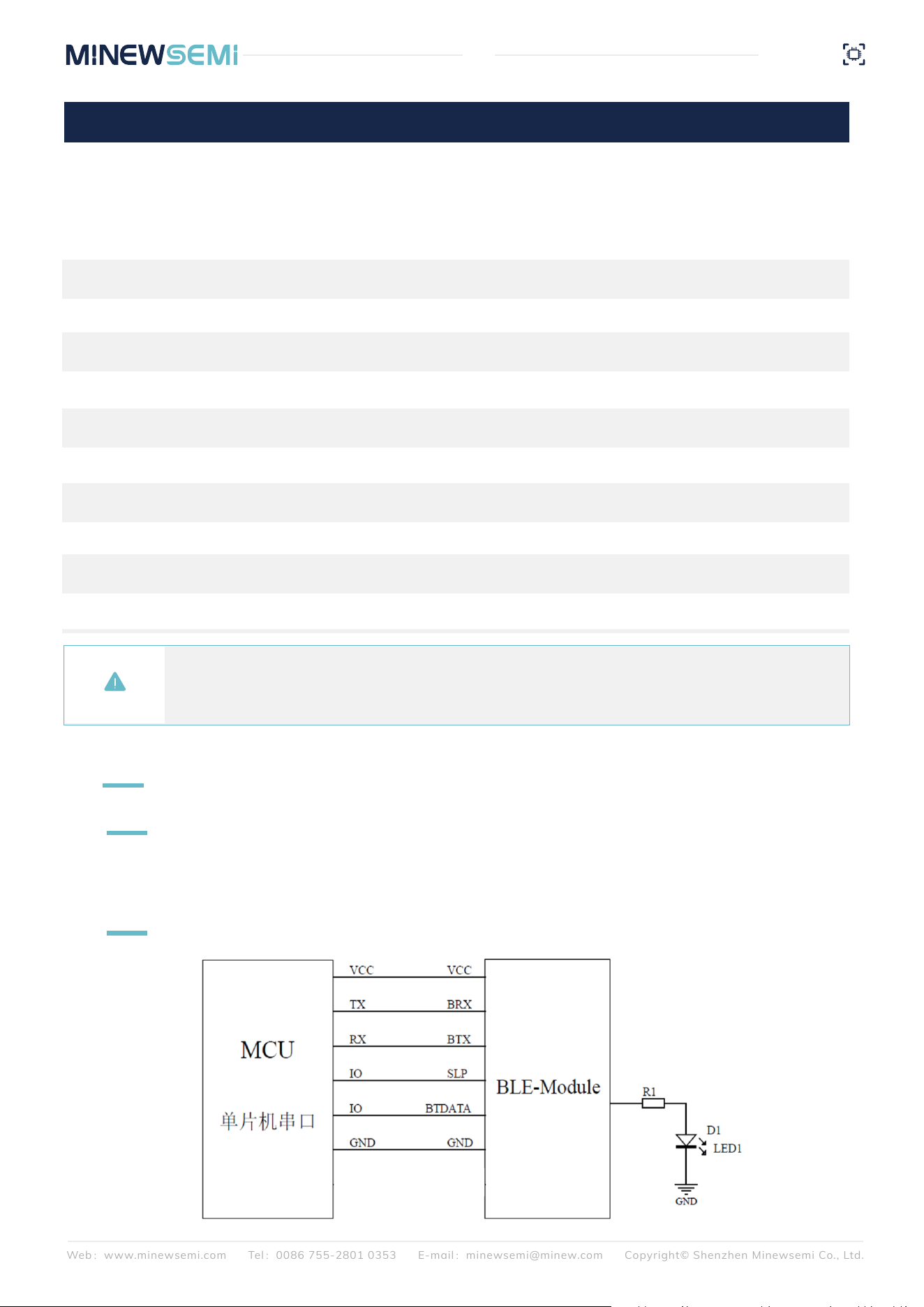
PC serial port assistant: Search and download "Serialport Utility" in your browser. The PC serial port assistant is
used to debug the UART interface of the module.
6
MODULE OPERATION INSTRUCTION
6.1 Tool
6.2 Wiring
Web:www.minewsemi.com Tel:0086 755-2801 0353 E-mail:minewsemi@minew.com Copyright© Shenzhen Minewsemi Co., Ltd.
08
ME54BS0A
Datasheet
Note:
The ME54BSOA controls the power amplifier using 8 general-purpose input/output pins A1 to B4, namely nRF21540.
These 8 pins can also be used for external connections. If they are used for other input/output functions,
please avoid possible signal conflicts.
Pin Number Symbol Type Definition
27
28
29
30
31
32
A1
A2
A3
A4
B1
P0.01
P0.00
P2.10
P2.09
GND
GND
P1.07
P1.14
P1.10
P1.09
P1.13
FIFO_FULL
LED
GPIO
GPIO
GND
GND
GPIO/AN3
GPIO/AN7
GPIO
GPIO
GPIO/AIN6
General-purpose I/O port
General-purpose I/O port
General-purpose I/O port
General-purpose I/O port
General-purpose I/O port
General-purpose I/O port
General-purpose I/O port
Not connected: Low level
Connection status: High level
Is there space in the UART receive buffer?
0: The module has available space; transmission is possible
1: The module will have no available space
The SoC working voltage is 1.71V-3.6V, to ensure a stable function, supply voltage should be 2.3V-3.6V.
Web:www.minewsemi.com Tel:0086 755-2801 0353 E-mail:minewsemi@minew.com Copyright© Shenzhen Minewsemi Co., Ltd.
09
ME54BS0A
Datasheet
6.2.1 Power Supply
When pull SLP low, the module in broadcast mode. BLE device can be found by smartphone APP, Device
name: Minew_Vxxxxx (default), module can be connected with smartphone and enters connection mode.
When pull SLP high, device will enter sleep mode.
6.2.2 SLP(Sleep/Wake)
Note:This pin cannot be left floating to avoid unpredictable errors.
The BTDATA pin is only valid when SLP is low. SLP is low, BTDATA is low, and when the module is in a broad-
cast state, all UART data will be considered as instructions. When the module is connected, all data is consid-
ered transparent.
6.2.3 BTDATA(UART Control)
Note:This pin cannot be left floating to avoid unpredictable errors.
When both SLP and BTDATA in low level, UART port will be activated, the module TX and RX should be
connected to MCU RX and TX, then start to communicate through UART.
During module testing, the TX and RX pins can be connected to a USB-to-UART module. This allows sending
and receiving UART data through a PC serial port assistant.
6.2.4 UART Interface:TX and RX
CON_IND is used to indicate the connection status. It outputs a high level when connected and a low level in
other states. This pin can be used to wake up the connected MCU, helping to save power.
6.2.5 CON_IND
FIFO_FULL is used to indicate whether the cache is full or not. When sending large amount of data from MCU
to module, this pin can be used for status checking. If it is high, then the FIFO is full, and UART data should not
be transmitted further to avoid packet loss.
6.2.6 FIFO_FULL
Command Mode
When not connected, all data input via the UART is treated as commands. Please refer to the command refer-
ence for details.
Pass-through Mode
After connection:
In master pass-through mode, sending a disconnect command via UART will terminate the current connec-
tion. All other UART and BLE data are transmitted in pass-through mode.
In slave pass-through mode, except for the authentication password sent by the master, all other UART and
BLE data are transmitted in pass-through mode.
6.2.7 Operating Mode
Note: If a USB-to-UART module is not available, you can connect the TX and RX pins of two Bluetooth
modules in reverse. Then, connect each module to a separate phone, and you can test data pass-through
between the two devices.
Web:www.minewsemi.com Tel:0086 755-2801 0353 E-mail:minewsemi@minew.com Copyright© Shenzhen Minewsemi Co., Ltd.
10
ME54BS0A
Datasheet
Master-related parameters include scan timeout, scan interval and connection interval; the connection interval
setting applies to both master and slave modes. Scan timeout and scan interval are only valid under the
master module:
After connecting VCC and GND, grounding the SLP and BTDATA pins, the module is in an unconnected state
this time, which means the module is in command mode with the UART enabled. Commands can be sent to set
and query parameters.
For all device commands, the return messages are consistent:
A successful command returns: 54544D3A4F4B0D0A00 (TTM:OK\r\n\0)
A failed command returns: 54544D3A4552500D0A00 (TTM:ERP\r\n\0)
After sending a valid configuration command, the parameters take effect immediately
(Except for baud rate and service/characteristic UUID, which only take effect after a reset command is issued).
These settings will not be saved after power-off at this stage.
Parameters are saved to flash only after a reset command is sent.
The following is the list of configuration commands:
Note:
In the command descriptions, the first and second lines represent the HEX format and ASCII string format,
respectively.
The command parsing format is determined by:
TTM:CMM-0 (string mode), or
TTM:CMM-1 (HEX mode).
The returned parameters will be displayed according to the current command format. It is recommended to
send commands using the corresponding format as well.
By default, the module operates in string mode.
If string mode is selected, parameters are set in string format. For example, if the advertising interval is set
to 10 units:
Command: TTM:ADP-10
If HEX mode is selected, parameters are set in HEX format. For example, if the advertising interval is set to
10 units:
Command: TTM:ADP-0A
Other parameters follow the same rule.
6.2.8 Command Instructions
Note:
1. If scan parameters (such as scan interval and scan timeout) are modified after scanning has
commenced, the current scan parameters will not be updated immediately, however, the query results
will be updated. Therefore, please avoid modifying scan parameters when a scan is in progress.
2. To facilitate device discovery, RSSI, broadcast name and MAC address filtering functions have been
added. Only one of MAC address filtering and broadcast name filtering can be active at a time; when
MAC address filtering is enabled, broadcast name filtering is automatically disabled, and vice versa.
54544D3A434D4D2D<Para>
TTM:CMM-<Para>
54544D3A434D4D3F
TTM:CMM?
Return TTM:CMM-<Para>\r\n\0, with the
returned parameters displayed according to
the current instruction format.
In hexadecimal mode, Para represents 0x00
to 0x01; in string mode, it represents '0' to
'1'. Its length is 1 byte.
0: String mode
1: HEX mode
Command Parsing
Format
Query the current
status of command
parsing format
Function
Command(hex/ASCII)
Description
Web:www.minewsemi.com Tel:0086 755-2801 0353 E-mail:minewsemi@minew.com Copyright© Shenzhen Minewsemi Co., Ltd.
11
ME54BS0A
Datasheet
54544D3A5343542D<Para>
TTM:SCT-<Para>
54544D3A5343543F
TTM:SCT?
Return TTM:SCT-<Para>\r\n\0, The returned
parameters are displayed according to the
current command format.
Para is represented in hexadecimal as 0x00
to 0x24 or as a string from 0 to 36. Para*5S,
0 means scanning all the time and output
scanning result in real time.
Set Scan Timeout
Set Scan Timeout
Function
Command(hex/ASCII)
Description
54544D3A5349572D<Para>
TTM:SIW-<Para>
54544D3A5349573F
TTM:SIW?
Return TTM:SIW-<Para>\r\n\0, Para: Hexadec-
imal
The returned parameters are displayed
according to the current command format.
Actual scanning interval: <Para> * 10ms
<Para> May be represented in hexadecimal
as 0x01 to 0x64, or as a string from 1 to 100,
with a length of 1 byte.
Set Scan Interval
Query Scan Interval
54544D3A5253492D<Para>
TTM:RSI-<Para>
54544D3A5253493F
TTM:RSI?
Return TTM:RSI-<Para>\r\n\0
Representing values from 0xE2 to 0x88 in
hexadecimal or -120 to -30 dBm in string
format, with a length of 1 byte. RSSI filtering is
disabled when values fall below -100 dBm.
Set RSSI Filtering
Query RSSI
Filtering
54544D3A404E462D<Para>
TTM:AVF-<Para>
54544D3A404E463F
TTM:ANF?
Return TTM:ANF-<Para>\r\n\0,Para: Filter value
for previously configured broadcast names.If not
enabled, <Para> is empty.
Only when scanning detects a device broadcast
name containing the configured name will the
corresponding device information be output.
Configured broadcast name filter value string
length: 1-16 bytes Hexadecimal length: 1-16 bytes
Set Broadcast Name
Filtering
Query Broadcast
Name Filtering
54544D3A404E462D
TTM:ANF-
54544D3A4D41462D<Para>
TTM:MAF-<Para>
When MAC address filtering is enabled, scan
results are output in real time in the format:
0xAA+MAC+RSSI+adv_data+0x0D0A. If no
filtered devices are detected, the following is
output: TTM:NO-DEVICE\r\n\0
X denotes hexadecimal, with string length being
12 bytes and hex length 6 bytes.
Cancel broadcast name filtering
Cancel Broadcast
Name Filtering
Setting MAC
Address Filtering
54544D3A4D41463F
TTM:MAF?
54544D3A4D41462D
TTM:MAF-
Cancel MAC address filtering
Return TTM:MAF-<Para>\r\n\0,The returned
parameters are displayed according to the
current command format.
If not enabled, <Para> is empty.
Query MAC
Address Filtering
Cancel MAC Address
Filtering
Web:www.minewsemi.com Tel:0086 755-2801 0353 E-mail:minewsemi@minew.com Copyright© Shenzhen Minewsemi Co., Ltd.
12
ME54BS0A
Datasheet
54544D3A4955462D<Para>
TTM:IUF-<Para>
54544D3A4955463F
TTM:IUF?
Return: TTM:IUF-<Para>\r\n\0
Returned parameters are displayed according
to the current command format.
If not enabled, <Para> is empty.
When iBeacon UUID filtering is enabled, scan
results are output in real time in the format:
0xAA+MAC+RSSI+adv_data+0x0D0A. If no filtered
devices are detected, the following is output:
TTM:NO-DEVICE\r\n\0
<Para> denotes a string length of 32 bytes,
corresponding to a hexadecimal length of 16 bytes.
Configure iBeacon
UUID Filtering for
Scanning
Query and Scan
iBeacon UUIDs with
Filtering
Function
Command(hex/ASCII)
Description
54544D3A4955462D
TTM:IUF-
54544D3A4D44462D<Para>
TTM:MDF-
Configure vendor data filter values; device
information will only be output when scanned
vendor data contains the specified name.
<Para> Character string length: 1-16 bytes;
hexadecimal length: 1-16 bytes.
Cancel iBeacon UUID filteringCancel iBeacon
UUID Filtering
Set Broadcast Data
Filter Value
54544D3A4D44463F
TTM:MDF?
54544D3A4D44462D
TTM:MDF-
Cancel manufacturer data filtering
Query vendor data filter value,
Returns: TTM:MDF-<Para>\r\n\0
<Para> denotes the previously configured
vendor data filter value
If not enabled, <Para> remains empty
Query Broadcast
Data Filter Values
Cancel broadcast
data filtering
During the connection setup process, relevant commands must be sent to put the device into Bluetooth
mode, such as scanning for devices and initiating a connection with a specific device. Once connected, when
transmitting data, the system checks all data to determine whether it constitutes a disconnection command.
This command is only supported in master mode
Command correctly return: TTM:SCAN-
NING\r\n\0, error return
Upon scan timeout, output device information for
discoverable devices with broadcast names in
the following format:
XXXXXXXXXXXX Minew_V5.44H\r\n
XXXXXXXXXXXX Minew_V5.43H\r\n
XXXXXXXXXXXX Minew_V5.42H\r\n TTM:ER-
P\r\n\0, after scanning to the device serial port
output 10 RSSI value of the strongest device,
scanning timeout is 0 or MAC address filtering
scanning output results format 0xAA + MAC +
RSSI + adv_data + 0x0D0A, the rest of the
output for MAC + broadcast name
This command is only supported in master mode
The command returns correctly: TTM:S-
CAN-STOP\r\n\0, Indicates that scanning has
stopped on the master;incorrectly returns
TTM:ERP\r\n\0
Turn On Scanning 54544D3A5343414E
TTM:SCAN
Stop Scanning 54544D3A5343414E2D53544F50
TTM:SCAN-STOP
Function
Command(hex/ASCII)
Description
Web:www.minewsemi.com Tel:0086 755-2801 0353 E-mail:minewsemi@minew.com Copyright© Shenzhen Minewsemi Co., Ltd.
13
ME54BS0A
Datasheet
A master device may initiate a connection with a slave device with a specified MAC address and enter
connection mode. When the MAC address of the target device is known, there is no need to perform a scan;
instead, a connection command may be sent directly.
When switching from master mode to slave mode, the device must first ensure it is in an unconnected state,
call the ‘Set Role’ command, and then call the ‘Reset’ command to successfully switch to the slave role; the
reverse process applies.
Note: The above commands are only valid in master mode; if the device is not in master mode,
sending these commands will return TTM:ERP\r\n\0.
Apart from the four commands mentioned above, all other device commands will return
TTM:OK\r\n\0 in both master and slave modes, provided that the parameter range requirements
are met; the parameters will take effect in the corresponding role.
54544D3A524F4C2D<Para>
TTM:ROL-<Para>
54544D3A524F4C3F
TTM:ROL?
Return TTM:ROL-<Para>\r\n\0; the parameters
returned by <Para> are displayed in accor-
dance with the current command format
<Para>Can be represented in hexadecimal
as 0x00–0x01, or as the characters “0”–“1”;
length: 1 byte,
0: Slave mode, 1: Master mode; other values
are invalid
Set Role
Query Role
Function
Command(hex/ASCII)
Description
This command is only supported in master mode
MAC address, which may be represented either
in hexadecimal or as a string:
String: TTM:CONN-XXXXXXXXXXXX
Hex: 54544D3A434F4E4E2DXXXXXXXXXXXX
Command return: TTM:CONNING\r\n\0, indicat-
ing connection in progress
TTM:CONN-TOUT\r\n\0, connection timeout
TTM:NO-DEVICE\r\n\0, device not found
TTM:CONN-MAC-XXXXXXXXXXXXX\r\n\0,
connected
TTM:MAC-DCON-XXXXXXXXXXXXX\r\n\0,
Disconnect TTM:ERP\r\n\0, Command Error
The command must be configured according to
the current command format.
This command is only supported in master
mode and takes effect only after connection
Response:
TTM:C-MAC-DCON-XXXXXXXXXXXX\r\n\0
indicates disconnection from slave, error
returns TTM:ERP\r\n\0
Commands must be configured according to
the current command format.
Connect to the
Specified MAC
54544D3A434F4E4E2D<MAC>
TTM:CONN-<MAC>
Master Disconnects
All Connections
From Slave
54544D3A444953432D414C4C
TTM:DISC-ALL
Function
Command(hex/ASCII)
Description
Web:www.minewsemi.com Tel:0086 755-2801 0353 E-mail:minewsemi@minew.com Copyright© Shenzhen Minewsemi Co., Ltd.
14
ME54BS0A
Datasheet
In slave mode, various parameters for broadcast and connection processes can be configured and queried,
as follows:
54544D3A52454E2D <Para>
TTM:REN-<Para>
54544d3a52454e3f
TTM:REN?
Return TTM:REN-<Para>\r\n\0,The returned
name conforms to the current command
format.
Para: Hexadecimal length 1–16 bytes, string
length 1–16 bytes
Set Broadcast
Name
Query Broadcast
Name
Function
Command(hex/ASCII)
Description
54544D3A4144502D <Para>
TTM:ADP-<Para>
54544D3A4144503F
TTM:ADP?
Return TTM:ADP-<Para>\r\n\0,The returned
parameters are displayed according to the
current command format.
Set the broadcast interval; <Para> can be
expressed in hexadecimal as 0x01 to 0x14, or as a
string from “1” to “28”. Please note that when
using a string, do not prefix valid digits with a zero.
For values between 1 and 20, the actual broadcast
interval is <Para> × 100 ms
For values between 21 and 28, starting from 20
ms, the actual broadcast interval is 20 + (<Para> -
21) * 10 ms, increasing in increments of 10 ms
Note: The larger the broadcast interval, the lower
the power consumption, maximum broadcast
interval 2s
Set Broadcast
Interval
Query Broadcast
Interval
54544D3A4144442D <Para>
TTM:ADD-<Para>
54544D3A4144443F
TTM:ADD?
If the broadcast data is "Minew Tech"
Return: TTM:ADD-[Minew Tech]\r\n\0,
The returned parameters are displayed
according to the current command format.
<Para>May be represented either in hexadeci-
mal or as a string, with hex lengths ranging
from 1 to 16 bytes and string lengths from 1 to
16 characters.
Set Broadcast
Data
Query Broadcast
Data
54544D3A5049442D <Para>
TTM:PID-<Para>
54544D3A5049443F
TTM:PID?
If the product identification code is 0x0639
Return: TTM:PID-[0639]\r\n\0
The returned parameter display follows the
current command format
The string is 4 bytes; the hexadecimal
representation is 2 bytes.
Set Factory ID
Query Factory ID
54544D3A5549443F
TTM:UID?
If the UUIDs are 0xFFF0, 0xFFF1, 0xFFF2
respectively
Return: TTM:UID-[FFF0FFF1FFF2]\r\n\0
The returned parameters are displayed
according to the current command format
Query Service UUID
54544D3A5549442D <Para>
TTM:UID-<Para>
<Para>May be represented either in hexadeci-
mal or as a string. The string length is 12 bytes,
while the hex length is 6 bytes.
Service_UUID + Rx_UUID + Tx_UUID. Each
UUID occupies 2 bytes and cannot be set to
zero. The UUIDs for service, rx, and tx must not
be identical. Changes do not take effect
immediately; a reset command must be sent for
them to become active. The queried UUID
represents the currently active UUID.
Set Service UUID
Web:www.minewsemi.com Tel:0086 755-2801 0353 E-mail:minewsemi@minew.com Copyright© Shenzhen Minewsemi Co., Ltd.
15
ME54BS0A
Datasheet
54544D3A4D4F442D <Para>
TTM:MOD-<Para>
54544d3a4d4f443f
TTM:MOD?
Return TTM:MOD-<Para>\r\n\0, The returned
parameters are displayed according to the
current command format.
Can be represented in hexadecimal as 0x00 to
0x01, or as the string "0" to "1", with a length of
1 byte.
0: Broadcast transparent transmission of
broadcast packets
1: Broadcast IBeacon broadcast packets
Set Broadcast
Mode
Query Broadcast
Mode
Function
Command(hex/ASCII)
Description
54544D3A4D414A3F
TTM:MAJ?
If major is 0x1234
Returns: TTM:MAJ-[1234]\r\n\0
Returned parameters are displayed according
to the current command format
Query Major
54544D3A4149442D <Para>
TTM:AID-<Para>
54544D3A4149443F
TTM:AID?
If the UUID is
0x11223344556677889900AABBCCDDEEFF,
the response shall be:
TTM:AID-[11223344556677889900AABBC-
CDDEEFF]\r\n\0
The returned parameters shall be displayed in
accordance with the current command format.
It may be represented either in hexadecimal
notation or as a string, with the string length
being 32 bytes and the hexadecimal length
being 16 bytes.
Set IBeacon
Broadcasting's
UUID
Query IBeacon
Broadcasting's UUID
54544D3A4D414A2D<Para>
TTM:MAJ-<Para>
It may be represented in hexadecimal
notation or as a string, with the string length
being 4 bytes and the hexadecimal length
being 2 bytes.
Set Major
54544D3A4D494E3F
TTM:MIN?
If Minor is 0x1235
Return: TTM:MIN-[1235]\r\n\0
The returned parameters are displayed
according to the current command format.
Query Minor
54544D3A5057453F
TTM:PWE?
Query whether connection password is
enabled
Return: TTM:PWE-<Parameter>\r\n\0
Returned parameter display follows current
command format
Query Connection
Mode
54544D3A4D494E2D <Para>
TTM:MIN-<Para>
It may be represented in hexadecimal
notation or as a string, with the string length
being 4 bytes and the hexadecimal length
being 2 bytes.
Set Minor
54544D3A5057443F
TTM:PWD?
If the connection password is minew123
Returns: TTM:PWD-[minew123]\r\n\0
The returned parameters are displayed
according to the current command format.
Query Connection
Password
54544D3A5057442D <Para>
TTM:PWD-<Para>
May be represented in hexadecimal or as a
string,
with string lengths ranging from 1 to 8 bytes
and hexadecimal lengths from 1 to 8 bytes.
Set Connection
Password
54544D3A5057452D <Para>
TTM:PWE-<Para>
Whether the device requires a password for
connection:
<Para> may be represented in hexadecimal as
0x00 to 0x01, or as a string from "0" to "1",
with a length of 1 byte.
0: Disabled
1: Enabled (effective only from the slave end;
when enabled, a correct password must be
entered within 6 seconds after connection,
otherwise the connection will be terminated)
Set Connection
Mode
Web:www.minewsemi.com Tel:0086 755-2801 0353 E-mail:minewsemi@minew.com Copyright© Shenzhen Minewsemi Co., Ltd.
16
ME54BS0A
Datasheet
Whether in master or slave mode, all configuration commands require a reset command to take effect, while
query commands return the relevant parameters; if a command error occurs, the response is TTM:ERP\r\n\0.
For the device as a whole, the baud rate and connection interval commands take effect regardless of
whether the device is in master or slave mode.
54544D3A4250532D <Para>
TTM:BPS-<Para>
54544D3A4250533F
TTM:BPS?
Return TTM:BPS-<Para>\r\n\0,
The returned parameters are displayed
according to the current command format.
Length: 1 Byte, It may be represented in
hexadecimal as 0x00 to 0x08; alternatively, it
may be expressed as the characters "0" to "7",
corresponding to 9600/
19200/38400/57600/115200/256000/460800/9
21600 (unit: bps) respectively.
Modifications will not take effect immediately; a
reset command must be issued for them to
become active.
Set Baud Rrate
Query Baud Rate
Function
Command(hex/ASCII)
Description
54544D3A4349542D <Para>
TTM:CIT-<Para>
54544D3A4349543F
TTM:CIT?
Return to TTM:CIT-<Para>\r\n\0,
The returned parameters are displayed
according to the current command format
Length: 1 byte, <Para> may be assigned
hexadecimal values from 0x01 to 0x64, or
string values from 1 to 100, corresponding to a
minimum connection interval of <Para> * 10
ms. The maximum connection interval equals
the minimum connection interval plus 20 ms.
Set Connection
Interval
Query Connection
Interval
54544D3A5750592D<Para>
TTM:WPY-<Para>
<Para> can be in HEX format 0x01–0x02 or
string format "1"–"2", length: 1 byte
1: Standard mode
2: Long Range mode
In Long Range mode, the transmission
distance is longer, but the data rate is reduced.
Set Working PHY
54544D3A5041522D<Para>
TTM:PAR-<Para>
Configure whether UART parity is enabled.
<Para> can be in HEX format 0x00–0x02 or
string format "0"–"2", length: 1 byte
0: Disabled
1: Odd parity
2: Even parity
After setting successfully and resetting the
module, the host (e.g., serial assistant tool)
must also be configured to the corresponding
parity setting.
Set UART Parity
54544D3A5750593F
TTM:WPY?
Check the current working PHY of the device.
Return: TTM:WPY-<Para>\r\n\0
The returned parameter is displayed according
to the current command format.
Query Working PHY
54544D3A5041523F
TTM:PAR?
Check whether UART parity is enabled.
Return: TTM:PAR-<Para>\r\n\0
The returned parameter is displayed according
to the current command format.
Query UART Parity
Web:www.minewsemi.com Tel:0086 755-2801 0353 E-mail:minewsemi@minew.com Copyright© Shenzhen Minewsemi Co., Ltd.
17
ME54BS0A
Datasheet
Note: During normal transparent transmission, the baud rate parameter is recommended to be set to
a maximum of 115200. At 115200 baud with a 40ms connection interval, transparent transmission
remains relatively stable. At baud rates exceeding 115200, or when using shorter connection intervals,
packet loss or disconnection may occur.
54544D3A5550592D<Para>
TTM:UPY-<Para>
54544D3A5550593F
TTM:UPY?
Return: TTM:UPY-<Para>\r\n\0
The returned parameter is displayed according
to the current command format.
<Para> can be in HEX format 0x00–0x01 or
string format "0"–"1", length: 1 byte
0: Enable 1M PHY update
1: Enable 2M PHY update
The 2M PHY update only takes effect in
standard mode (non-coded PHY).
The 2M PHY provides higher data rates but
shorter transmission distance.
Set PHY Update
(1M / 2M)
Query PHY Update
Setting
Function
Command(hex/ASCII)
Description
54544d3a4d4143(2d)3f
TTM:MAC-? or TTM:MAC?
54544d3a564552(2d)3f
TTM:VER-? or TTM:VER?
If the module's firmware version is "V1.0.0",
return: TTM:VER-[V1.0.0]\r\n\0, where the
version is represented as a string.
Return TTM:MAC-<Para>\r\n\0,If the module's
MAC address is 11:22:33:44:55:66,
Return: TTM:MAC-[112233445566]\r\n\0,
MAC displayed according to current command
format.
Read MAC Address
Read Version
Information
54544d3a5253542d464143
TTM:RST-FAC
Reset module parameters to factory defaults
without parameters.
Restore Factory
Settings
54544d3a5253542d535953
TTM:RST-SYS
Success will return TTM:OK\r\n\0
Reset
6.3 Operation Examples
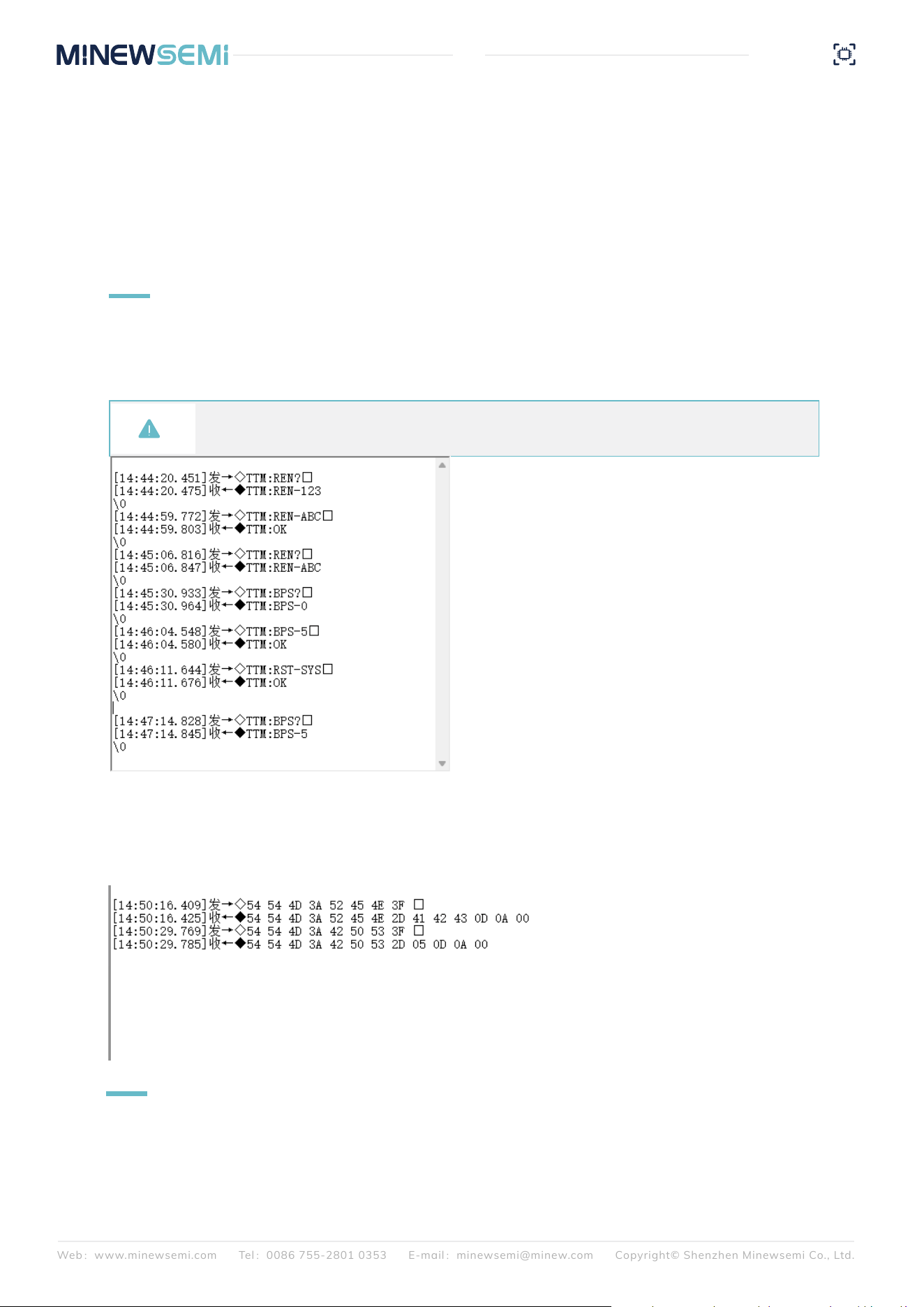
6.3.1 Factory Default Parameters
Broadcast Name: Minew_Vxxxxx
Serial port baud rate: 9600bps,8N1
Transmit power: 20dBm
Minimum and maximum connection interval: 20ms -
40ms
Device Role: Master Slave Simultaneous
Default parameters related to master mode:
Scanning timeout: 10s
Scanning interval: 100ms
Default parameters related to slave mode:
Broadcast interval: 1s
Broadcast mode: transparent broadcast package
Custom data: MinewTech
Web:www.minewsemi.com Tel:0086 755-2801 0353 E-mail:minewsemi@minew.com Copyright© Shenzhen Minewsemi Co., Ltd.
18
ME54BS0A
Datasheet
Connection password enable: not enabled
Connection password: minew123
Major: 0x1234
minor: 0x1235
UUID: 74278BDA-B644-4520-8F0C-720EAF059935
DC_RC: DC-DC enabled, external 32K
6.3.2 Parameter Modification Example
Connect all pins according to the wiring, ground SLP and BTDATA, the device enters the unconnected state, at
this time you can set the parameters, regardless of whether the device is in the state of the master or the slave,
all the parameters can be set, and some of the parameters take effect immediately. After sending the reset
command, all parameters are powered down and saved.
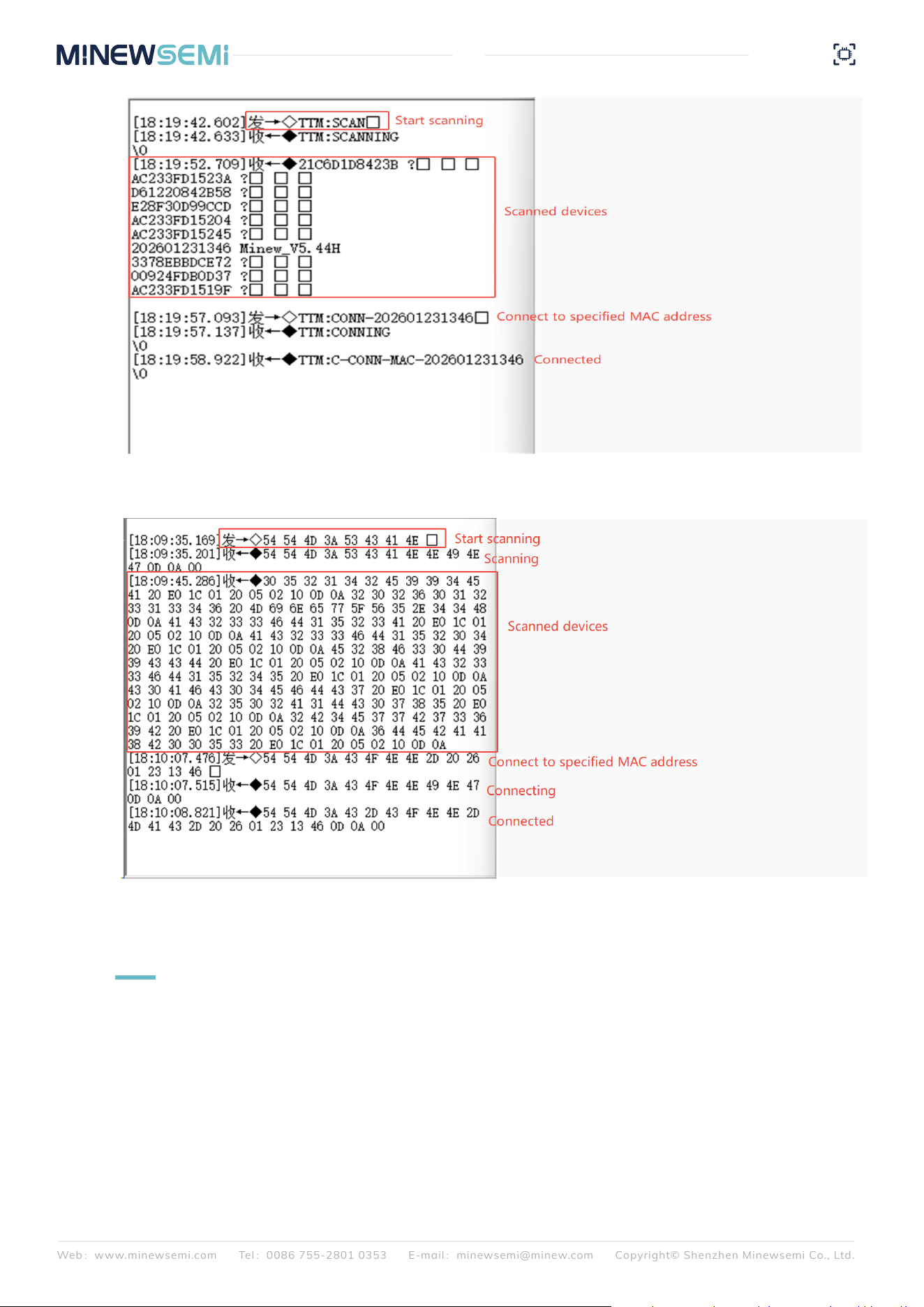
6.3.3 Scanning and Connecting to Devices
Send the 54544D3A5343414E (TTM:SCAN) command to scan for a device and obtain its MAC address. The
scanned device returns MAC + broadcast name information. Send the
54544D3A434F4E4E2D323032363031323331333436(TTM:CONN-202601231346) command and the
module will connect the device with MAC address 202601231346. The device connected will return
54544D3A432D434F4E4E2D4D41432D2026012313460D0A00(TTM:CONN-MAC-202601231346\r\n\0)
.Once connected you can perform data passthrough.
When querying device parameters, as parameters are displayed according to the currently configured format,
for instance, if the command parsing format is set to HEX, selecting ASCII display may result in parameter
positions appearing as garbled characters. In such instances, it is necessary to set the display to HEX. The
parameters correspond to positions following the 2D designation, as illustrated in the figure below.
Note: When you need to modify multiple parameters, you can send all the setting commands first
and then send the reset command.
Web:www.minewsemi.com Tel:0086 755-2801 0353 E-mail:minewsemi@minew.com Copyright© Shenzhen Minewsemi Co., Ltd.
19
ME54BS0A
Datasheet
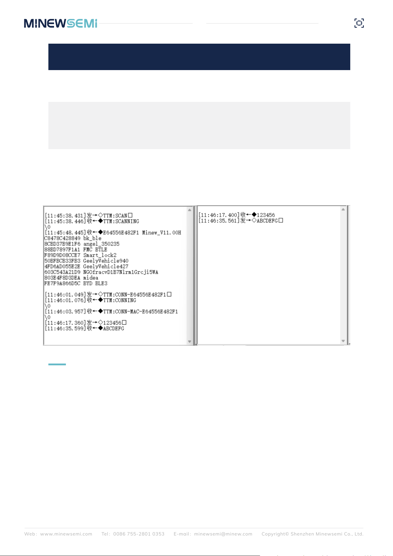
6.3.4 Transparent Transmission Test Procedure
Data passthrough is possible after the connected command is returned in step 6.3.3 The prerequisite for
correct communication between the module and the slave device is that the slave device must have the same
services, features, and their UUIDs and attributes as the module.
Relevant information is provided below:
Web:www.minewsemi.com Tel:0086 755-2801 0353 E-mail:minewsemi@minew.com Copyright© Shenzhen Minewsemi Co., Ltd.
20
ME54BS0A
Datasheet
Module data reception, the data sent from the
device to the module shall not exceed 244 Byte
per packet.
Module data sending, the module has to do
automatic packetization, data more than 244
Byte will be automatically divided into 244
packets sent to the slave device.
FFF1 notify 244
FFF2 write 244
Eigenvalue
UUID
Executable
Operation
Packet
Length
Notes
6.3.5 Slave Broadcasting
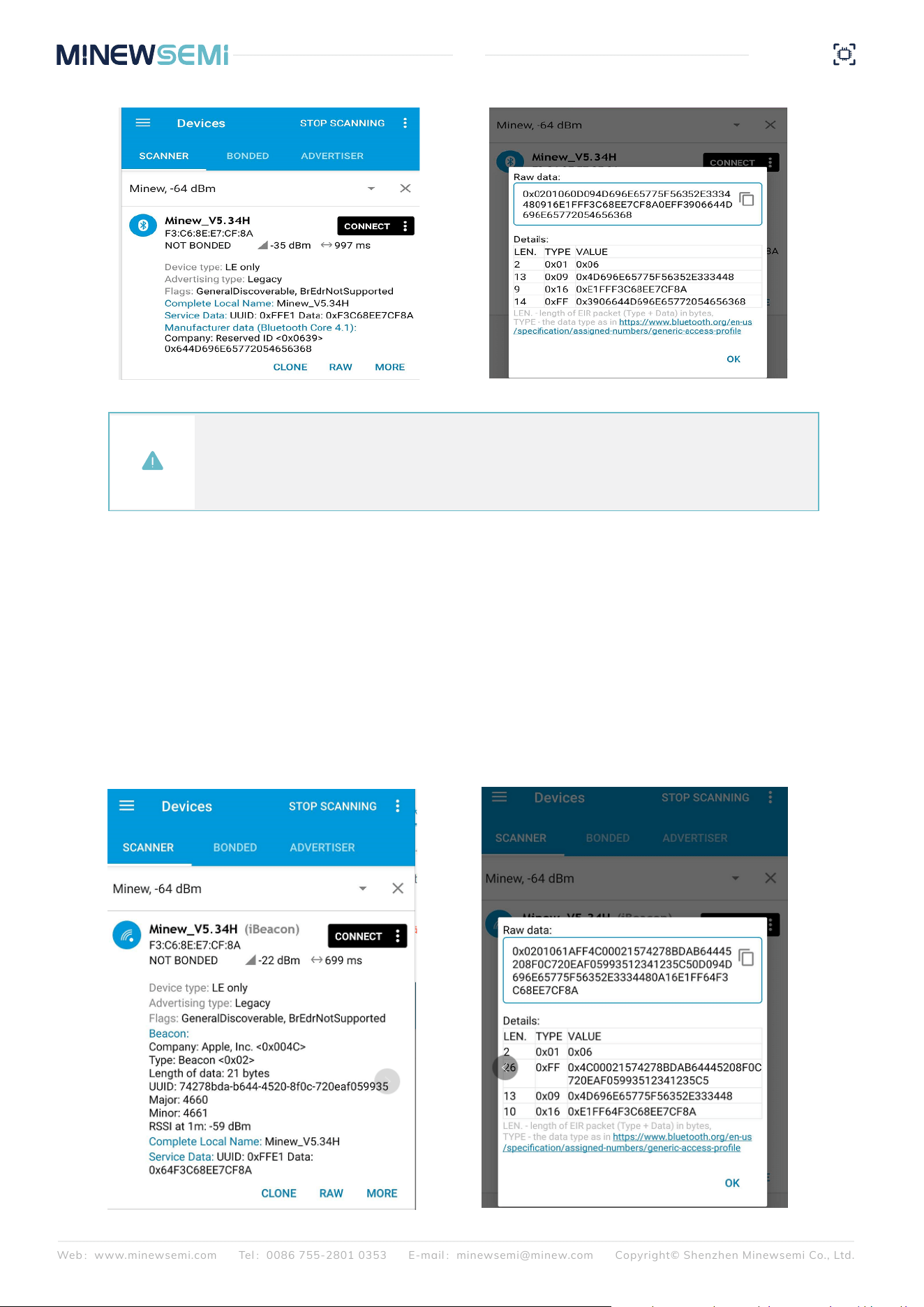
When the device acts as a slave, When the SLP pin is low, the device is in broadcast mode.Using the nRF
Connect app, you can scan for devices. Once the device is detected, click on "Raw" to view the raw data,
which is the unparsed data from the scan. After parsing according to BLE data types, you can refer to the
Details section.
BLE broadcast data follows a specific format: Length + Type + Content. The content can vary, while the type is
fixed, and the length is determined by the content. The device has two broadcast formats: pass-through
broadcast packets and iBeacon broadcast packets. Both formats include four types: Flag (0x01), Broadcast
Name (0x09), Service Data (0x16), and Manufacturer Data (0xFF).
The diagram below shows the pass-through broadcast packet: Flag, Broadcast Name, and Service Data are
included in the broadcast data packet, while Manufacturer Data is found in the response data packet. The
content of the Service Data includes the Service Data UUID (E1FF) and MAC Address. The Manufacturer Data
consists of the Company ID (3906), Battery Level Information (1 byte), and Custom Data.
Taking the connection of a master module to a pass-through slave module as an example, data can be
transmitted immediately after connection.
Wiring: Follow the pin configuration instructions in Section 6.2: Set SLP and BTDATA to low, and connect TX,
RX, GND and VCC.
Web:www.minewsemi.com Tel:0086 755-2801 0353 E-mail:minewsemi@minew.com Copyright© Shenzhen Minewsemi Co., Ltd.
21
ME54BS0A
Datasheet
The diagram below shows the iBeacon broadcast packet: Flag and Manufacturer Data are included in the
broadcast data packet, while Service Data and Broadcast Name are found in the response data packet. The
broadcast data packet must follow this fixed format to comply with the iBeacon protocol definition.
In the Manufacturer Data, 4C 00 represents Apple's Company ID, and 02 15 is the fixed format for iBeacon,
followed by the Proximity UUID (16 bytes), Major (2 bytes), Minor (2 bytes), and Measured Power (1 byte).
In iBeacon broadcast mode, the Manufacturer Data can only have the Proximity UUID, Major, and Minor
values modified.
The Service Data consists of the Service Data UUID (FFE1), Battery Level Information, and MAC Address.
Note: The iOS side cannot access the MAC address field, so the MAC address is placed back into the
broadcast packet to ensure that the iOS app can retrieve the device's MAC address. Additionally, WeChat
Mini Programs cannot access the response data packet, so the MAC address is included in the service data
of the broadcast packet to ensure that iOS devices using WeChat Mini Programs can also obtain the
device's MAC address.
Web:www.minewsemi.com Tel:0086 755-2801 0353 E-mail:minewsemi@minew.com Copyright© Shenzhen Minewsemi Co., Ltd.
22
ME54BS0A
Datasheet
6.3.6 Slave Pass-Through
Based on 6.3.5, when connecting the device using a mobile app, keep the BTDATA pin low to enable data
pass-through. If BTDATA is not low, it does not affect the device's broadcasting and connection capabilities; it
simply prevents pass-through functionality.
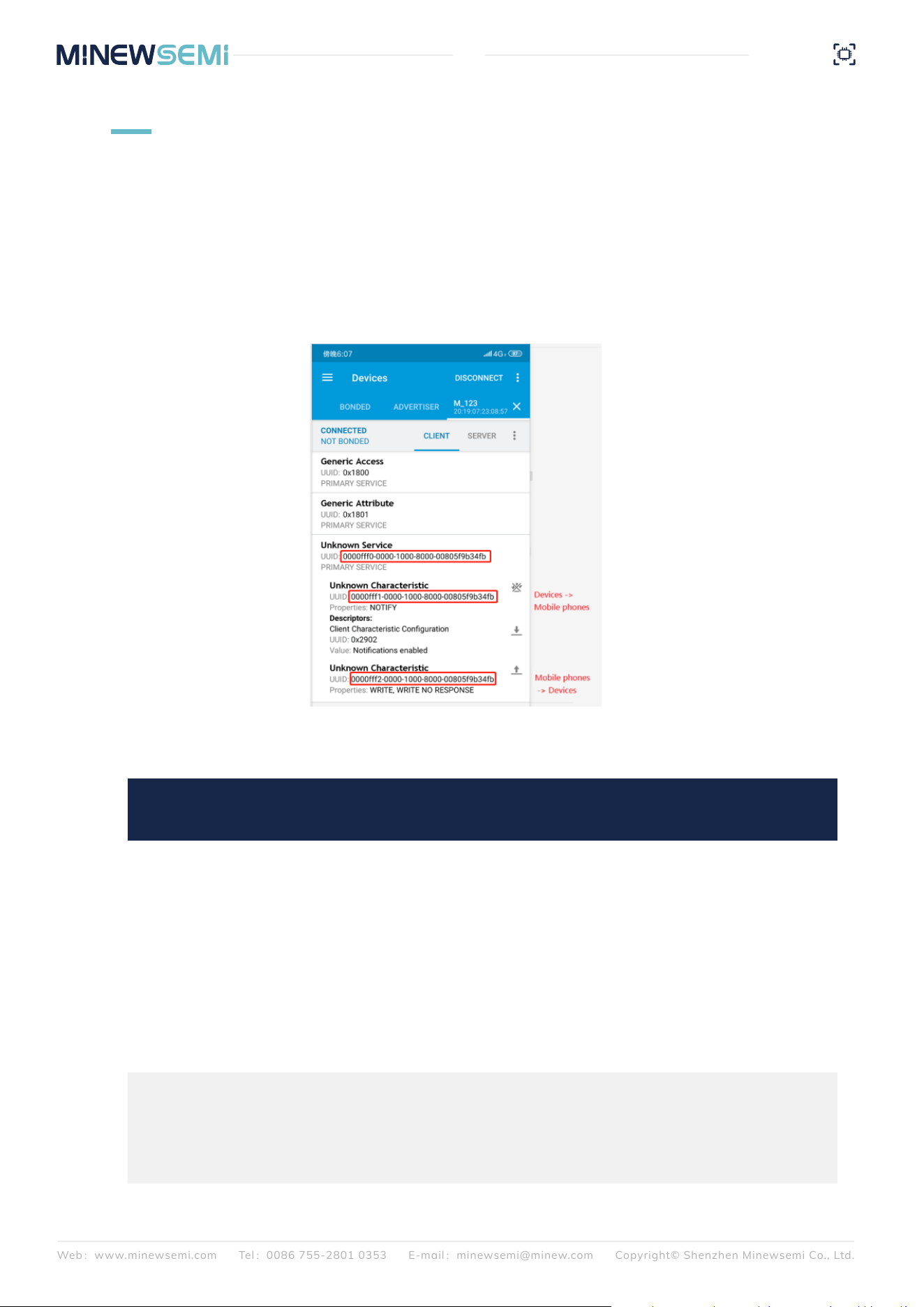
Using nRF Connect, you can view the specific Service, Characteristic, and their corresponding Properties.
The UUID consists of an Alias UUID (2 bytes, located at the 3rd and 4th bytes in the figure) combined with a
Base UUID (the remaining 14 bytes). In the pass-through program, the services and characteristics utilize a
standard base UUID, and the following explanation will use the Alias UUID for clarification.
When sending data to the module via the serial
interface, the module will forward it to the
phone. The phone must enable notifications to
receive the data. The maximum packet size that
the module can send in one transmission is 244
bytes.
Note: The firmware automatically handles
packet fragmentation, so there is no need to
manually divide the data into packets based on
the maximum length. However, each packet
must not exceed 10 kB, and you should consider
the transmission rate to avoid issues such as
packet loss or disconnection.
The phone sends data to the module and
forwards it to the serial port. When using the
API interface function to write data, the
maximum length of data written at one time is
244 bytes
FFF1 notify 244
FFF2 write 244
Eigenvalue
UUID
Executable
Operation
Maximum
Packet Length
Notes
FFF0 is the Service UUID.
FFF1 is for data received by the phone, with the module sending data.
FFF2 is for data sent by the phone, with the module receiving data
Web:www.minewsemi.com Tel:0086 755-2801 0353 E-mail:minewsemi@minew.com Copyright© Shenzhen Minewsemi Co., Ltd.
23
ME54BS0A
Datasheet
7
8
MECHANICAL DRAWING
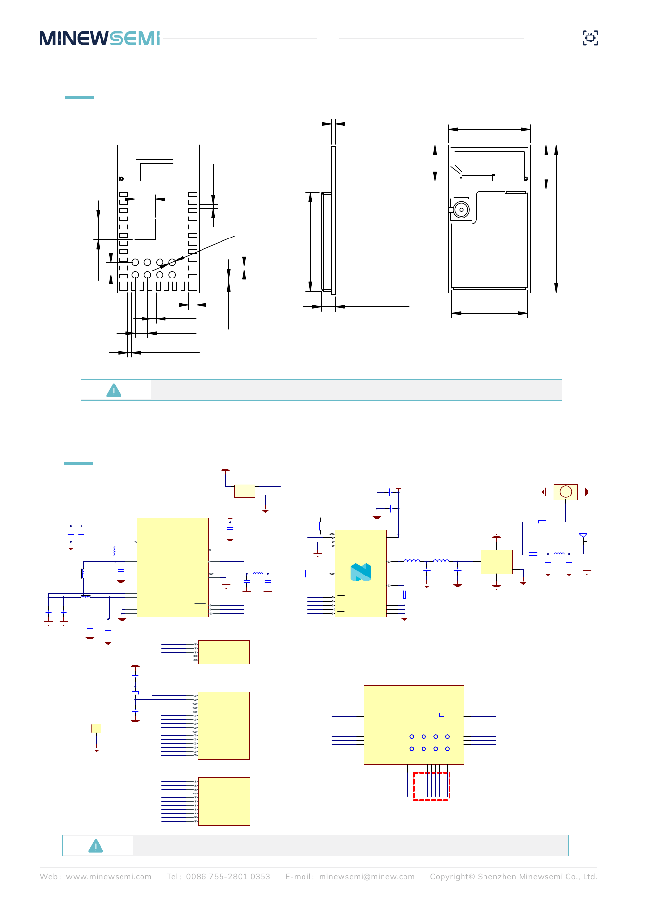
ELECTRICAL SCHEMATIC
Default unit:mm Default tolerance:±0.15
Notice:Before placing an order, please confirm the specific configuration required with the salesperson.
DECA
A4
DECD
A5
VSS
A6
DCC
A7
VDD
B7
VSS
G4
DECRF
B1
ANT
D1
XC1
A1
XC2
A2
SWDIO
F2
VDD
G3
SWDCLK
E3
RESET
D2
VSS_PA
C2
nRF54L15
U1A
P0.02
E2
P0.03/CK
E1
P0.04/CK
D3
P0.00
G1
P0.01
F1
U1B
P1.00/XL1
C5
P1.08/EXTREF/CLK16M/CK
F7
P1.01/XL2
C6
P1.02/NFC1
C7
P1.03/NFC2/CK
D5
P1.04/AIN0/CK
D6
P1.05/AIN1
E6
P1.06/AIN2
D7
P1.07/AIN3
E7
P1.10
C3
P1.11/AIN4/CK
C4
P1.12/AIN5/CK
A3
P1.13/AIN6
B4
P1.14/AIN7
B5
P1.09
B3
P1.15
B6
U1C
P2.00
G6
P2.01/CK
G7
P2.02
F6
P2.03
E5
P2.04
F5
P2.05
G5
P2.06/CK
F4
P2.07/SWO
E4
P2.08
D4
P2.09
F3
P2.10
G2
U1D
MC2
MC1
ML1
FB1
GND
4
OUT
1
GND
2
IN
3
Y1
32MHz
GND
VCC
MC3
GND
DECD
MC5
MC4
DECA
GNDGND
GND
MC7
GND
VCC
GND
XC1
XC2
nRESET
SWDCLK
SWDIO
XC1
XC2
GND
GND
MC8
ML3
MC9
GND GND
MC10
ML5
MC11
GND GND
1
2
Antenna
GND
P0.00
P0.01
P0.02
P0.03/CK
P0.04/CK
P1.00/XL1
P1.01/XL2
P1.02/NFC1
P1.03/NFC2/CK
P1.04/AIN0/CK
P1.05/AIN1
P1.06/AIN2
P1.07/AIN3
P1.08
P1.13/AIN6
P1.14/AIN7
P1.15
P2.00
P2.01/CK
P2.02
P2.03
P2.04
P2.05
P2.06/CK
P2.07/SWO
P2.08
P2.09
P2.10
1
GND
R1
ANT
1
GND
2
GND
3
AJ1
GNDGND
FB2
DECRF
MC14
GND
GND
C3
C2
VCC
L2
C4 C5
GND
GND
nRF21540
VSS
1
ANT_SEL
8
TX_EN
9
ANT1
2
ANT2
3
MODE
4
VDD
5
VDD
6
RX_EN
7
TRX
10
PDN
11
SCK
12
MOSI
13
MISO
14
CSN
15
VSS
16
VSS
17
U2
C1
L1
R4
GND
GND
P1.13/AIN6
P1.14/AIN7
R3
P1.07/AIN3
P1.11/AIN4/CK
P1.09
P1.10
P1.15
P1.12/AIN5/CK
P1.09
P1.10
P1.11/AIN4/CK
P1.12/AIN5/CK
Input
1
GND
2
GND
3
Output
4
GND
5
U3
GND
GND
GND
R2
Y2
32.768kHz
DCC
MC15
GND
MC16
MC17
GND
GND
1
1
2
2
3
3
4
4
5
5
6
6
7
7
8
8
9
9
10
10
11
11
12
12
13
13
14
14
15
15
16
16
17
17
18
18
19
19
20
20
21
21
22
22
23
23
24
24
25
25
26
26
27
27
28
28
29
29
30
30
31
31
A1
A1
A2
A2
A3
A3
A4
A4
B1
B1
B2
B2
B3
B3
B4
B4
A
B
1 2 3 4
32
32
32
ME54BS0A
GND
P2.05
P2.00
P2.01/CK
VCC
GND
P2.06/CK
P2.04
P2.02
P2.08
P2.03
P2.07/SWO
GND
GND
P2.09
P2.10
P0.00
P0.01
SWDIO
SWDCLK
P0.02
P0.03/CK
nRESET
P0.04/CK
P1.08
P1.06/AIN2
P1.05/AIN1
P1.02/NFC1
P1.03/NFC2/CK
P1.04/AIN0/CK
GND
P1.14/AIN7
P1.07/AIN3
P1.13/AIN6
P1.11/AIN4/CK
P1.12/AIN5/CK
P1.09
P1.15
P1.10
The ME54BS0A controls the power amplifier using 8
g
eneral-purpose input/output pins, namely nRF21540.
T
hese 8 pins can also be used for external connections.
I
f they are used for other input/output functions, please
avoid possible signal conflicts.
GND
0.5
1.70±0.1
12.01
10±0.1
18±0.1
4.4
5.37
9.24
1
0.5
0.5
0.45
0.5
2.5
2.5
Ø0.8
1.5
0.47
1.5
Web:www.minewsemi.com Tel:0086 755-2801 0353 E-mail:minewsemi@minew.com Copyright© Shenzhen Minewsemi Co., Ltd.
24
ME54BS12
Datasheet
9
PCB DESIGN
This document is provided as a recommended design reference for wireless modules and does not constitute any
explicit or implied guarantee of performance or compliance. Due to differences in PCB layout, enclosure structure,
antenna selection, and application environments of the end product, this document cannot guarantee RF perfor-
mance in all scenarios. Users must conduct sufficient RF performance and compliance verification after completing
the final product design and shall bear full responsibility for design and application outcomes. Our company
reserves the right to modify the contents of this document without prior notice.
9.1 Disclaimer
Board Edge Priority Rule
The RF output/antenna side of the module must face the edge of the main PCB to ensure that antenna radiation is
directed outward from the board without obstruction. Placing the module in a closed central area of the PCB is
strictly prohibited.
Keep-Out Area Rule
A 0.5 mm area around the module body must be kept clear. Non-ground components and non-ground signal traces
are prohibited within this area. Within 4 mm around the RF side of the module, copper pours, unrelated compo-
nents, and non-RF signal traces are strictly prohibited.
Interference Isolation Rule
The module must maintain a minimum safe distance from strong interference sources. Adjacent placement on the
same layer is prohibited. Isolation using different PCB layers and shielding covers is recommended. General isola-
tion requirements are as follows:
9.2 Core Rules for Module Placement
20mm
20mm
15mm
25mm
Interference Source Type
Minimum Recommended Isolation Distance
Structural Clearance Rule
The minimum distance between the module and metal screws, clips, standoffs, and other structural parts must be
≥5 mm. At least 4 mm of SMT soldering and rework clearance must be reserved around the module. The RF side of
the module must not be enclosed inside a fully metal cavity.
Multiple Modules on the Same PCB
When placing multiple wireless modules of the same or different types on the same PCB, the minimum spacing
between modules must be ≥50 mm to avoid mutual interference.
DC-DC switching power supplies,
power inductors, power transformers
USB 3.0 / HDMI 2.0 / DDR
/ High-speed SDIO interfaces
MCU high-frequency clock circuits,
Ethernet PHY chips
Displays, cameras,
FPC cables with wiring

Web:www.minewsemi.com Tel:0086 755-2801 0353 E-mail:minewsemi@minew.com Copyright© Shenzhen Minewsemi Co., Ltd.
25
ME54BS12
Datasheet
Grounding Design
The main PCB must maintain a complete and continuous ground plane. Splitting the ground plane within the
module projection area or RF surrounding area is strictly prohibited. All module ground pins must be soldered. At
least one grounding via should be placed near each ground pad and connected to the main ground plane. A
complete ground plane with dense grounding vias may be placed under the non-RF area of the module to improve
shielding performance.
Power Supply Design
Decoupling capacitor combinations must be placed close to the module power input pins. The trace length between
capacitor pads and power pins should be ≤0.5 mm, and at least two grounding vias should be placed near the
ground terminal. For switching power supply applications, a π-type filter circuit footprint must be reserved near the
module power input pins.
RF Trace Design
The entire RF path must maintain a strict 50 Ω characteristic impedance (tolerance ±10%). RF traces should be as
short as possible and routed preferably in straight lines. Sharp or right-angle corners are prohibited; curved routing
with a radius ≥3 times the trace width is recommended. Branch traces and stub traces are prohibited. A continuous
reference ground plane must exist beneath the RF traces, and no other signal traces should be routed within 3
times the trace width on either side. Ground shielding should be applied throughout the RF routing.
Control Interface Design
Control signal traces such as UART, SPI, and I2C should be routed away from RF areas with short and simple
routing paths and continuous ground shielding. Parallel routing adjacent to RF traces is prohibited. ESD protection
devices must be placed close to external PCB connectors and must not be placed near module pins.
Footprint Design
Strictly use the standard PCB footprint provided by our company. Unauthorized modification of pad size or spacing
is prohibited to ensure soldering reliability.
9.3 GENERAL PCB DESIGN REQUIREMENTS
Do not place the RF side of the module facing the inside of the PCB or away from the board edge.
Do not place copper pours, components, or fully enclosed metal housings without openings over the antenna
area.
Do not route RF traces across split ground planes, without a complete reference ground, or with right-angle
corners.
Do not place modules adjacent to strong interference sources or split the ground plane in the module area.
Do not leave module ground pins unconnected or inadequately grounded.
9.4 DESIGN RESTRICTIONS
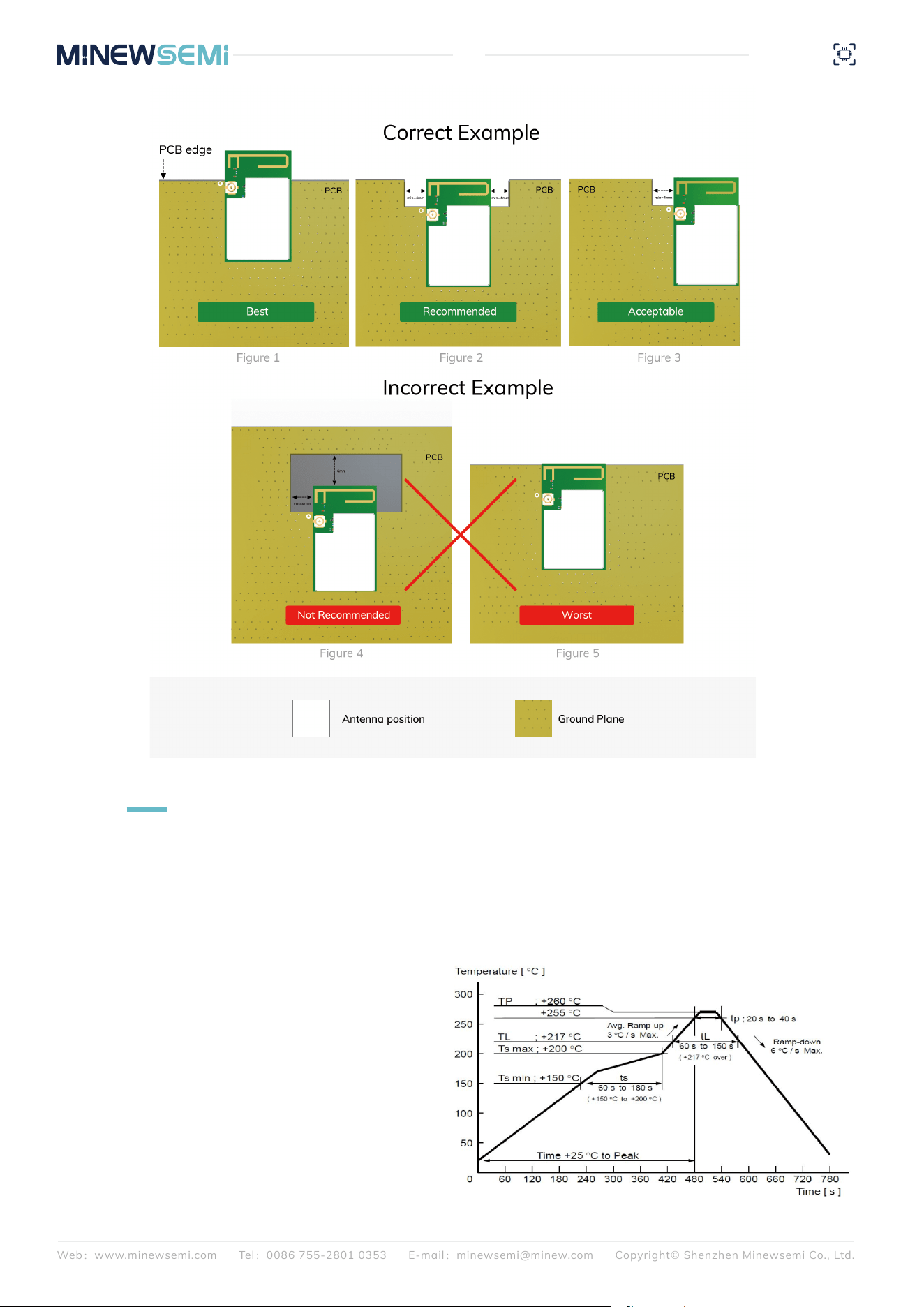
For end products, antenna position significantly affects overall system performance. The module should preferably
be placed at the edge or corner of the PCB to maximize the clearance area and reduce interference from surround-
ing components. The PCB area directly beneath the module antenna should be hollowed out to keep the antenna
region suspended, while no signal traces, metal objects, or other interference sources should exist within 3–5 mm
around the antenna area. The figure below demonstrates an example of proper module placement on the main
PCB for optimal RF performance. The first recommended layout method should be used whenever possible, as the
module antenna design has been tuned and optimized based on this configuration.
9.5 MODULE PLACEMENT EXAMPLE
3) For SMT modules, a stencil thickness of 0.1–0.12 mm
is recommended, with a 1:0.9 aperture ratio for the pins
and no flare.
4) After opening, if the entire package is not used at
once, it should be stored in a vacuum to prevent
long-term exposure to air, which can cause moisture
absorption and pad oxidation. If there is a gap of 7 to 30
days before reuse, it is recommended to bake the tape at
65-70°C for 24 hours without unrolling it before returning
to SMT.
5) ESD protection measures should be implemented
before using SMT.
Web:www.minewsemi.com Tel:0086 755-2801 0353 E-mail:minewsemi@minew.com Copyright© Shenzhen Minewsemi Co., Ltd.
26
ME54BS12
Datasheet
10
REFLOW AND SOLDERING
1) Perform SMT according to the reflow oven temperature profile provided below, with a maximum temperature of 260°C;
2) Follow IPC/JEDEC standards; Peak temperature: < 260°C; Number of reflows: ≤2 times; For SMT involving double-sided
placement, it is recommended that the module side undergoes reflow soldering only once. For any special processes, please
contact our company.
Web:www.minewsemi.com Tel:0086 755-2801 0353 E-mail:minewsemi@minew.com Copyright© Shenzhen Minewsemi Co., Ltd.
27
ME54BS0A
Datasheet
11
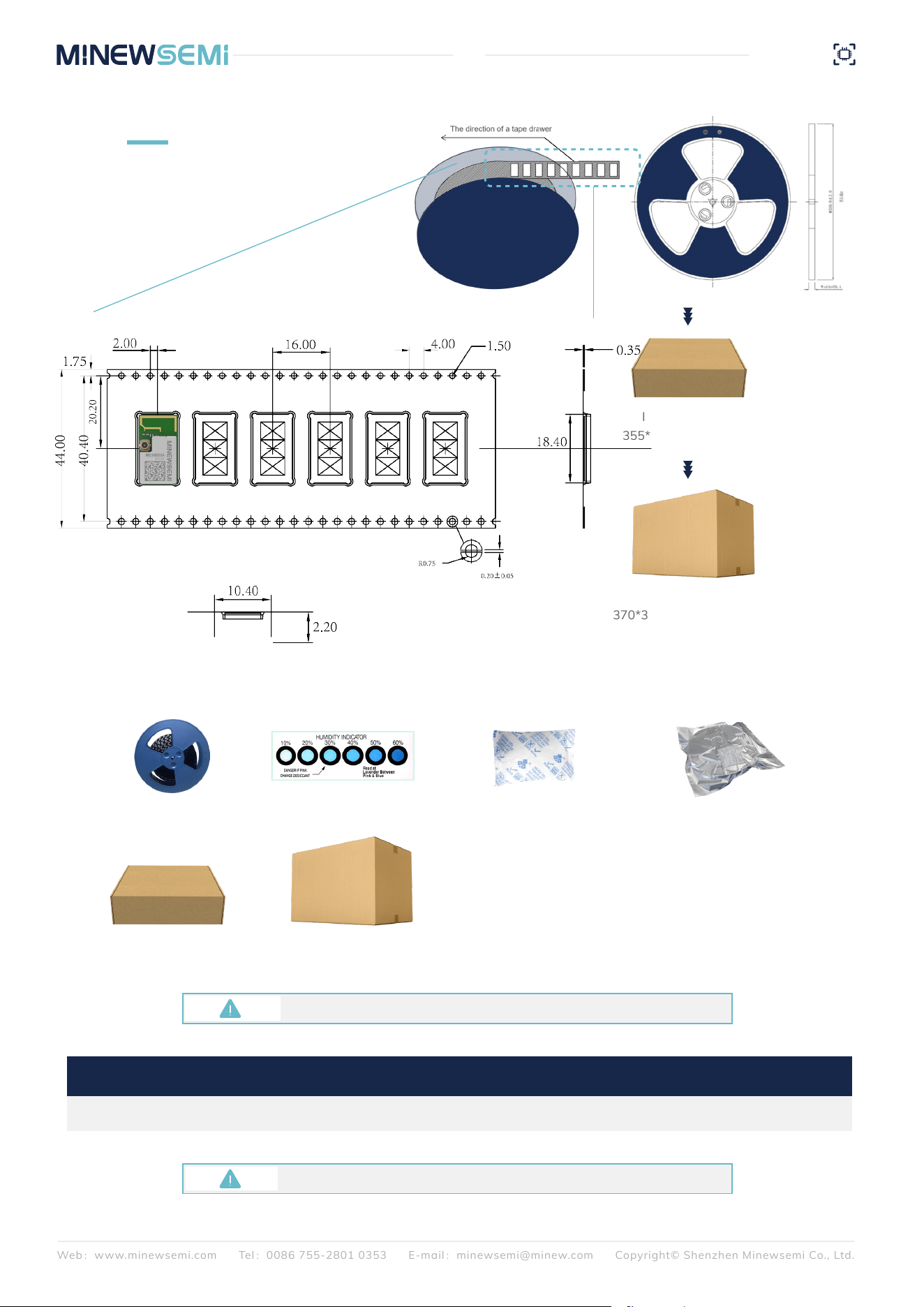
PACKAGE INFORMATION
Carrier tape packaging tray Humidity Indicator
(1 pcs/bag)
Desiccant
(placed in a vacuum bag)
Vacuum bag
Moisture-proof label (attached to the vacuum bag)
Certification label (attached to the vacuum bag)
Outer box label
Inner carton(*5)
355*345*65mm,±5mm
Inner carton(*5)
355*345*65mm,±5mm
370*358*350mm,±10mm
Outer carton
370*358*350mm,±10mm
Outer carton
Note: Default weight tolerance all are within 10g(except the special notes)
Default unit:mm Default tolerance:±0.1
Remarks
General material list for FCL packaging:
Other:
ME54BS0A 850PCS 484.5 g 1280.5 g
W=44mm,T=0.35mm
Packing Detail Specification Net Weight Gross Weight Dimension

Web:www.minewsemi.com Tel:0086 755-2801 0353 E-mail:minewsemi@minew.com Copyright© Shenzhen Minewsemi Co., Ltd.
28
ME54BS0A
Datasheet
This device complies with part 15 of the FCC Rules. Operation is subject to the following two conditions:
(1) This device may not cause harmful interference
(2) This device must accept any interference received, including interference that may cause undesired operation.
Any Changes or modifications not expressly approved by the party responsible for compliance could void the user's
authority to operate the device.
Note: This device has been tested and found to comply with the limits for a Class B digital device, pursuant to part 15
of the FCC Rules. These limits are designed to provide reasonable protection against harmful interference in a residen-
tial installation. This device generates uses and can radiate radio frequency energy and, if not installed and used in
accordance with the instructions, may cause harmful interference to radio communications. However, there is no guar-
antee that interference will not occur in a particular installation. If this device does cause harmful interference to radio
or television reception, which can be determined by turning the device off and on, the user is encouraged to try to correct
the interference by one or more of the following measures:
-Reorient or relocate the receiving antenna.
-Increase the separation between the device and receiver.
-Connect the device into an outlet on a circuit different from that to which the receiver is connected.
-Consult the dealer or an experienced radio/TV technician for help.
This module complies with FCC RF radiation exposure limits set forth for an Uncontrolled environment, This equipment
should be installed and operated with a minimum distance of 20 centimeters between the radiator and your body.
12
FCC WARNING
Requirement per KDB996369 D03
List the FCC rules that are applicable to the modular transmitter. These are the rules that specifically establish the
bands of operation, the power, spurious emissions, and operating fundamental frequencies. DO NOT list compli-
ance to unintentional-radiator rules (Part 15 Subpart B) since that is not a condition of a module grant that is
extended to a host manufacturer. See also Section 2.10 below concerning the need to notify host manufacturers
that further testing is required.3Explanation: This module meets the requirements of FCC part 15C(15.247).
2.2 List of applicable FCC rules
Describe use conditions that are applicable to the modular transmitter, including for example any limits on anten-
nas, etc. For example, if point-to-point antennas are used that require reduction in power or compensation for cable
loss, then this information must be in the instructions. If the use condition limitations extend to professional users,
then instructions must state that this information also extends to the host manufacturer’s instruction manual. In
addition, certain information may also be needed, such as peak gain per frequency band and minimum gain, specif-
ically for master devices in 5 GHz DFS bands.
Explanation: The EUT has a PCB Antenna, , and the antenna use a permanently attached
Antenna which is not replaceable.
2.3 Summarize the specific operational use conditions
If a modular transmitter is approved as a “limited module”, then the module manufacturer is responsible for approv-
ing the host environment that the limited module is used with. The manufacturer of a limited module must describe,
both in the filing and in the installation instructions, the alternative means that the limited module manufacturer
uses to verify that the host meets the necessary requirements to satisfy the module limiting conditions.
2.4 Limited module procedures

Web:www.minewsemi.com Tel:0086 755-2801 0353 E-mail:minewsemi@minew.com Copyright© Shenzhen Minewsemi Co., Ltd.
29
ME54BS0A
Datasheet
A limited module manufacturer has the flexibility to define its alternative method to address the conditions that limit
the initial approval, such as: shielding, minimum signaling amplitude, buffered modulation/data inputs, or power
supply regulation. The alternative method could include that the limited module manufacturer reviews detailed test
data or host designs prior to giving the host manufacturer approval.
This limited module procedure is also applicable for RF exposure evaluation when it is necessary to demonstrate
compliance in a specific host. The module manufacturer must state how control of the product into which the
modular transmitter will be installed will be maintained such that full compliance of the product is always ensured.
For additional hosts other than the specific host originally granted with a limited module,a Class II permissive
change is required on the module grant to register the additional host as a specific host also approved with the
module.
Explanation: The module is not a limited module.
For a modular transmitter with trace antenna designs, see the guidance in Question 11 of KDB Publication 996369
D02 FAQ – Modules for Micro-Strip Antennas and traces. The integration information shall include for the TCB
review the integration instructions for the following aspects: layout of trace design, parts list (BOM), antenna,
connectors, and isolation requirements.
a) Information that includes permitted variances (e.g., trace boundary limits, thickness, length, width, shape(s),
dielectric constant, and impedance as applicable for each type of antenna);
b) Each design shall be considered a different type (e.g., antenna length in multiple(s) of frequency, the wave-
length, and antenna shape (traces in phase) can affect antenna gain and must be considered);
c) The parameters shall be provided in a manner permitting host manufacturers to design the printed circuit (PC)
board layout;
d) Appropriate parts by manufacturer and specifications;
e) Test procedures for design verification;
f) Production test procedures for ensuring compliance.
The module grantee shall provide a notice that any deviation(s) from the defined parameters of the antenna trace,
as described by the instructions, require that the host product manufacturer must notify the module grantee that
they wish to change the antenna trace design. In this case, a Class II permissive change application is required to
be filed by the grantee, or the host manufacturer can take responsibility through the change in FCC ID (new applica-
tion) procedure followed by a Class II permissive change application.
Explanation: Yes, The module with trace antenna designs, and This manual has been shown the layout of trace
design,, antenna, connectors, and isolation requirements.
2.5 Trace antenna designs
It is essential for module grantees to clearly and explicitly state the RF exposure conditions that permit a host prod-
uct manufacturer to use the module. Two types of instructions are required for RF exposure information:
(1) to the host product manufacturer, to define the application conditions (mobile, portable – 20 cm from a person’s
body); and (2) additional text needed for the host product manufacturer to provide to end users in their end-product
manuals. If RF exposure statements and use conditions are not provided, then the host product manufacturer is
required to take responsibility for the module through a change in FCC ID (new application).
Explanation: This module complies with FCC RF radiation exposure limits set forth for an Uncontrolled environment,
This equipment should be installed and operated with a minimum distance of 20 centimeters between the radiator
and your body. This module is designed to comply with the FCC statement, FCC ID is: 2BDJ6-ME54BS0A
2.6 RF exposure considerations

Web:www.minewsemi.com Tel:0086 755-2801 0353 E-mail:minewsemi@minew.com Copyright© Shenzhen Minewsemi Co., Ltd.
30
ME54BS0A
Datasheet
Grantees are responsible for the continued compliance of their modules to the FCC rules. This includes advising host
product manufacturers that they need to provide a physical or e-label stating “Contains FCC ID” with their finished
product. See Guidelines for Labeling and User Information for RF Devices – KDB Publication 784748.
Explanation:The host system using this module, should have label in a visible area indicated the following texts:
"Contains FCC ID: 2BDJ6-ME54BS0A
2.8 Label and compliance information
A list of antennas included in the application for certification must be provided in the instructions.
For modular transmitters approved as limited modules, all applicable professional installer instructions must be
included as part of the information to the host product manufacturer. The antenna list shall also identify the anten-
na types (monopole, PIFA, dipole, etc. (note that, for example, an “omnidirectional antenna” is not considered to be
a specific “antenna type”).
For situations where the host product manufacturer is responsible for an external connector, for example, with an
RF pin and antenna trace design, the integration instructions shall inform the installer that a unique antenna
connector must be used on the Part 15 authorized transmitters used in the host product. The module manufactur-
ers shall provide a list of acceptable unique connectors.
Explanation: The EUT has a PCB Antenna, and the antenna uses a permanently attached antenna, which is unique.
2.7 Antennas
Additional guidance for testing host products is given in KDB Publication 996369 D04 Module Integration Guide.
Test modes should take into consideration different operational conditions for a stand-alone modular transmitter
in a host, as well as for multiple simultaneously transmitting modules or other transmitters in a host product.
The grantee should provide information on how to configure test modes for host product evaluation for different
operational conditions for a stand-alone modular transmitter in a host, versus with multiple, simultaneously trans-
mitting modules or other transmitters in a host.
Grantees can increase the utility of their modular transmitters by providing special means, modes, or instructions
that simulates or characterizes a connection by enabling a transmitter. This can greatly simplify a host manufactur-
er’s determination that a module as installed in a host complies with FCC requirements.
Explanation: Topband can increase the utility of our modular transmitters by providing instructions that simulates
or characterizes a connection by enabling a transmitter.
2.9 Information on test modes and additional testing requirements
Web:www.minewsemi.com Tel:0086 755-2801 0353 E-mail:minewsemi@minew.com Copyright© Shenzhen Minewsemi Co., Ltd.
31
ME54BS0A
Datasheet
• Be careful in handling or transporting products because excessive stress or mechanical shock may break
products.
• Handle with care if products may have cracks or damages on their terminals. If there is any such damage, the
characteristics of products may change. Do not touch products with bare hands that may result in poor solder
ability and destroy by static electrical charge.
Cognizant of our commitment to quality, we operate our own factory equipped with state-of-the-art production facilities and
a meticulous quality management system. We hold certifications for ISO9001, ISO14001, ISO27001, OHSA18001, BSCI.
Every product undergoes stringent testing, including transmit power, sensitivity, power consumption, stability, and aging
tests. Our fully automated module production line is now in full operation, boasting a production capacity in the millions, capa-
ble of meeting high-volume production demands.
15
QUALITY
13
STORAGE CONDITIONS
14
HANDLING CONDITIONS
Please use this product within 6 months after signing the receipt.
- This product should be stored without opening the package at an ambient temperature of 5~35°C and
a humidity of 20~70%RH.
- This product should be left for more than 6 months after receipt and should be confirmed before use.
- The product must be stored in a non-corrosive gas (CI2, NH3, SO2, NOx, etc.).
- To avoid damaging the packaging material, do not apply any excessive mechanical shocks, including but
not limited to sharp objects adhering to the packaging material and product dropping.
This product is suitable for MSL2 (based on JEDEC standard J-STD-020).
- After opening the package, the product must be stored at ≤30°C/<60%RH. It is recommended to use the
product within 3-6 months after opening the package.
- When the color of the indicator in the package changes, the product should be baked before welding.
Baking is not required for one year if exposure is limited to <30°C and 60%RH. Refer to MSL2 for exposure
criteria for moisture sensitivity level. If exposed to (≥168h@85°C/60%RH) conditions or stored for more than
one year, recommended baking conditions.
1. 120 +5/-5°C, 8 hours, 1 time
Products must be baked individually on heat-resistant trays because the materials (base tape, reel tape, and
cover tape) are not heat-resistant, and the packaging material may be deformed at temperatures of 120℃;
2、90℃ +8/-0℃,24hours,1times
The base tape can be baked together with the product at this temperature. Please pay attention to the unifor-
mity of heat.
32
ME54BS0A
Datasheet
This manual and all the contents contained in it are owned by Shenzhen Minewsemi Co., Ltd. and are protected by Chinese
laws and applicable international conventions related to copyright laws.
The certified trademarks included in this product and related documents have been licensed for use by MinewSemi. This
includes but is not limited to certifications such as BQB, RoHS, REACH, CE, FCC, BQB, IC, SRRC, TELEC, WPC, RCM, WEEE,
etc. The respective textual trademarks and logos belong to their respective owners. For example, the Bluetooth® textual
trademark and logo are owned by Bluetooth SIG, Inc. Other trademarks and trade names are those of their respective owners.
Due to the small size of the module product, the "®" symbol is omitted from the Bluetooth Primary Trademarks information in
compliance with regulations.
The company has the right to change the content of this manual according to the technological development, and the revised
version will not be notified otherwise. Without the written permission and authorization of the company, any individual,
company, or organization shall not modify the contents of this manual or use part or all of the contents of this manual in other
ways. Violators will be held accountable in accordance with the law.
16
COPYRIGHT STATEMENT
17
RELATED DOCUMENTS
For product change notifications and regular updates of Minewsemi documentation,
please register on our website: www.minewsemi.com
MinewSemi_Product_Naming_Reference_Manual
https://en.minewsemi.com/file/MinewSemi_Product_Naming_Reference_Manual_EN.pdf
MinewSemi_Connectivity_Module_Catalogue
https://en.minewsemi.com/file/MinewSemi_Connectivity_Module_Catalogue_EN.pdf
https://store.minewsemi.com
https://minewsemi.com
Gangzhilong Technology Park, Qinglong Road, Longhua
District, Shenzhen
minewsemi@minew.com
0086-755-2801 0353
SHENZHEN MINEWSEMI CO., LTD.
Innovative IoT Module Expert

