These appliances are intended to be used
for commercial applications, for example; in
kitchens for restaurants, canteens, hospitals,
and in commercial enterprises such as bakeries,
butcheries, etc., but not for continuous mass
production of food.
®
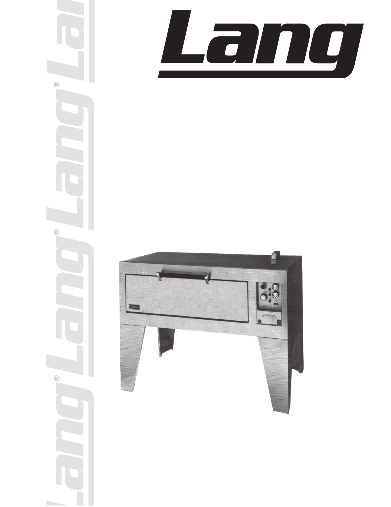
STANDARD BAKE
OVEN DO54B
STANDARD ROAST
OVEN DO54R
Commercial & Marine
Installation and
Operation
Instructions
2M-W476 REV E (08-23)
DO54B shown
THIS MANUAL MUST BE RETAINED FOR FUTURE REFERENCE.
READ, UNDERSTAND AND FOLLOW THE INSTRUCTIONS AND
WARNINGS CONTAINED IN THIS MANUAL.
FOR YOUR SAFETY
DO NOT STORE OR USE GASOLINE OR OTHER FLAMMABLE
VAPORS AND LIQUIDS IN THE VICINITY OF THIS OR ANY
OTHER APPLIANCE.
POST IN A PROMINENT LOCATION
INSTRUCTIONS TO BE FOLLOWED IN THE EVENT USER
SMELLS GAS. THIS INFORMATION SHALL BE OBTAINED BY
CONSULTING YOUR LOCAL GAS SUPPLIER.
AS A MINIMUM, TURN OFF THE GAS
AND CALL YOUR GAS COMPANY AND YOUR AUTHORIZED
SERVICE AGENT. EVACUATE ALL PERSONNEL FROM THE
AREA.
WARNING: IMPROPER INSTALLATION, ADJUSTMENT,
ALTERATION, SERVICE OR MAINTENANCE CAN CAUSE
PROPERTY DAMAGE, INJURY OR DEATH. READ THE
INSTALLATION, OPERATING AND MAINTENANCE
INSTRUCTIONS THOROUGHLY
BEFORE INSTALLING OR SERVICING THIS EQUIPMENT.
Model #: Purchased From:
Serial #: Location:
Date Purchased: Date Installed:
Purchase Order #: For Service, Call:

3
TABLE OF CONTENTS
CHAPTER
PAGE
TABLE OF CONTENTS............................................................................... 3
READ FIRST.................................................................................................... 4
EQUIPMENT DESCRIPTION..................................................................... 6
UNPACKING................................................................................................... 7
INSTALLATION.............................................................................................. 8
OPERATION................................................................................................... 11
MAINTENANCE & CLEANING PROCEDURES.................................. 13
TROUBLESHOOTING................................................................................. 14
WIRING DIAGRAMS.................................................................................... 16-17
EXPLODED VIEWS...................................................................................... 18-19
PARTS LISTS.................................................................................................. 20-22
4
IMPORTANT READ FIRST IMPORTANT
CAUTION:
EACH UNIT IS EXTREMELY HEAVY. FOR SAFE HANDLING,
INSTALLER SHOULD OBTAIN HELP AS NEEDED, OR EMPLOY
APPROPRIATE MATERIAL HANDLING EQUIPMENT (SUCH AS
A FORKLIFT, DOLLY, OR PALLET JACK) TO REMOVE THE UNIT
FROM THE SKID AND MOVE IT TO THE PLACE OF INSTALLATION.
CAUTION:
ANY STAND, COUNTER OR OTHER DEVICE ON WHICH THE
MELTER WILL BE LOCATED MUST BE DESIGNED TO SUPPORT
THE WEIGHT OF THE UNIT.
CAUTION:
SHIPPING STRAPS ARE UNDER TENSION AND CAN SNAP BACK
WHEN CUT.
DANGER:
THIS APPLIANCE MUST BE GROUNDED AT THE TERMINAL
PROVIDED. FAILURE TO GROUND THE APPLIANCE COULD
RESULT IN ELECTROCUTION AND DEATH.
HIGH
VOLTAGE
WARNING:
INSTALLATION OF THE UNIT MUST BE DONE BY PERSONNEL
QUALIFIED TO WORK WITH ELECTRICITY AND PLUMBING.
IMPROPER INSTALLATION CAN CAUSE INJURY TO PERSONNEL
AND/OR DAMAGE TO EQUIPMENT. UNIT MUST BE INSTALLED IN
ACCORDANCE WITH ALL APPLICABLE CODES.
NOTICE:
The data plate is located behind the circuit breaker door on oven.
The oven voltage, wattage, serial number, wire size, and clearance
specifications are on the data plate. This information should be
carefully read and understood before proceeding with the
installation.
NOTICE:
The installation of any components such as a vent
hood, grease extractors, fire extinguisher systems,
must conform to their applicable National, State and
locally recognized installation standards.
NOTICE:
During the first few hours of operation you may
notice a small amount of smoke coming o the
melter, and a faint odor from the smoke. This is
normal for a new melter and will disappear after the
first few hours of use.
CAUTION:
ALWAYS KEEP THE AREA NEAR THE APPLIANCE
FREE FROM COMBUSTIBLE MATERIALS.
CAUTION:
KEEP FLOOR IN FRONT OF EQUIPMENT CLEAN
AND DRY. IF SPILLS OCCUR, CLEAN IMMEDIATELY,
TO AVOID THE DANGER OF SLIPS OR FALLS.
5
IMPORTANT READ FIRST IMPORTANT
WARNING:
KEEP WATER AND SOLUTIONS OUT OF CONTROLS.
NEVER SPRAY OR HOSE CONTROL CONSOLE, ELECTRICAL
CONNECTIONS.
CAUTION:
MOST CLEANERS ARE HARMFUL TO THE SKIN, EYES, MUCOUS
MEMBRANES AND CLOTHING. PRECAUTIONS SHOULD BE
TAKEN TO WEAR RUBBER GLOVES, GOGGLES OR FACE SHIELD
AND PROTECTIVE CLOTHING. CAREFULLY READ THE WARNING
AND FOLLOW THE DIRECTIONS ON THE LABEL OF THE
CLEANER TO BE USED.
NOTICE:
Never leave a chlorine sanitizer in contact with stainless steel
surfaces longer than 10 minutes. Longer contact can cause
corrosion.
NOTICE:
Service on this, or any other, LANG appliance must be performed
by qualified personnel only. Consult your authorized service agent
directory or call the factory at 800-264-7827, or www.langworld.
com for the service agent nearest you.
WARNING:
BOTH HIGH AND LOW VOLTAGES ARE PRESENT
INSIDE THIS APPLIANCE WHEN THE UNIT IS
PLUGGED/WIRED INTO A LIVE RECEPTACLE. BEFORE
REPLACING ANY PARTS, DISCONNECT THE UNIT
FROM THE ELECTRIC POWER SUPPLY.
HIGH
VOLTAGE
CAUTION:
USE OF ANY REPLACEMENT PARTS OTHER THAN
THOSE SUPPLIED BY LANG OR THEIR AUTHORIZED
DISTRIBUTORS CAN CAUSE BODILY INJURY TO THE
OPERATOR AND DAMAGE TO THE EQUIPMENT AND
WILL VOID ALL WARRANTIES.

6
Exterior
Bake oven (Model: DO54B)
The oven dimensions are 20” (50.8cm) High, 36” (91.5cm) Deep, and 54”
(137cm) Wide.
The Sides, Bottom, and Rear wall are constructed stainless steel.
The bake oven has an 8” opening.
Roast oven (Model: DO54R)
The oven dimensions are 20” (50.8cm) High, 36” (91.5cm) Deep, and 54”
(137cm) Wide.
The Sides, Bottom, and Rear wall are constructed stainless steel.
The roast oven has an 8” opening.
Interior
Bake oven
The interior dimensions are 8” (20.3 cm) High, 30” (76.2 cm) Deep, and
38” (96.5 cm).
The interior is designed for baking on the rack or directly on the bottom
surface of the oven.
Roast oven
The interior dimensions are 12” (30.5 cm) High, 30” (76.2 cm) Deep, and
38” (96.5 cm).
The interior is designed for baking on the rack or directly on the bottom
surface of the oven.
Controls
The oven is provided with both an upper and a bottom-heating element.
The upper element is visible in the top of the oven the lower oven element
is under the bottom deck of the oven.
Both of these oven elements can be regulated with independently
controlled three heat switches. These switches provide to proper ratio of
top and bottom heat.
The oven is also provided with an adjustable thermostat that controls the
overall average temperature of the oven.
EQUIPMENT DESCRIPTION
Lang Model: DO54B & DO54R
Double Bake Oven Range
7
UNPACKING
Receiving the Oven
Upon receipt, check for freight damage, both visible and concealed. Visible damage
should be noted on the freight bill at the time of delivery and signed by the carrier's
agent. Concealed loss or damage means loss or damage which does not become
apparent until the merchandise has been unpacked. If concealed loss or damage is
discovered upon unpacking, make a written request for inspection by the carrier's
agent within 15 days of delivery. All packing material should be kept for inspection.
Do not return damaged merchandise to Lang Manufacturing Company. File your
claim with the carrier.
Location
Prior to un-crating, move the oven as near its intended location as practical. The
crating will help protect the unit from the physical damage normally associated with
moving it through hallways and doorways.
Un-crating
The oven will arrive completely assembled inside a wood frame covered by
cardboard box and strapped to a skid. Remove the cardboard cover, cut the
straps and remove the wood frame.
CAUTION OVEN WEIGHS 395 LBS (408 kilograms). FOR SAFE
HANDLING, INSTALLER SHOULD OBTAIN HELP AS NEEDED,
OR EMPLOY APPROPRIATE MATERIALS HANDLING
EQUIPMENT (SUCH AS A FORKLIFT, DOLLY, OR PALLET
JACK) TO REMOVE THE UNIT FROM THE SKID AND MOVE IT
TO THE PLACE OF INSTALLATION.
CAUTION ANY STAND, COUNTER OR OTHER DEVICE ON WHICH OVEN
WILL BE LOCATED MUST BE DESIGNED TO SUPPORT THE
WEIGHT OF THE OVEN (395 LBS.).
CAUTION SHIPPING STRAPS ARE UNDER TENSION AND CAN SNAP
BACK WHEN CUT.
Remove oven from skid and place in intended location.
INSTALLING THE LEGS
Legs are available for the single, double, and triple deck installations. Single deck
installations require a 27-inch leg. Double deck installations require a 16-inch and
triple deck installations require a 6-inch leg.
To install the 27-inch legs, place some cardboard on the floor and gently tip the oven
onto its back. Fasten two legs to the oven front corners using the four 5/16 inch
bolts provided in the leg kit. Lift the oven onto its front legs and block the back up
using one of the 27-inch legs set upside down in the center rear of the oven body.
Install the last 27-inch leg onto the oven body on the control side rear. Gently lift the
oven rear, remove the leg set to support the oven center and install it on the last rear
corner.
To install the 16-inch legs follow the same directions for the 27-inch legs before
stacking the second deck onto the bottom deck.
To install the 6-inch legs follow the same directions for the 27-inch legs before
stacking the second deck onto the bottom deck.
8
DANGER:
THIS APPLIANCE MUST BE GROUNDED AT THE TERMINAL
PROVIDED. FAILURE TO GROUND THE APPLIANCE COULD
RESULT IN ELECTROCUTION AND DEATH.
HIGH
VOLTAGE
WARNING:
INSTALLATION OF THE UNIT MUST BE DONE BY PERSONNEL
QUALIFIED TO WORK WITH ELECTRICITY AND PLUMBING.
IMPROPER INSTALLATION CAN CAUSE INJURY TO PERSONNEL
AND/OR DAMAGE TO EQUIPMENT. UNIT MUST BE INSTALLED IN
ACCORDANCE WITH ALL APPLICABLE CODES.
NOTICE:
The installation of any components such as a vent
hood, grease extractors, fire extinguisher systems,
must conform to their applicable National, State and
locally recognized installation standards.
NOTICE:
The data plate is located behind the circuit breaker door on oven.
The oven voltage, wattage, serial number, wire size, and clearance
specifications are on the data plate. This information should be
carefully read and understood before proceeding with the
installation.
INSTALLATION
ELECTRICAL CONNECTION
Single Deck
Install the legs to the oven.
Electrical service connections can be made through an 11/4 knockout in the
bottom of the oven.
Remove the cover attached to the oven circuit breakers for access.
Power connections can be made at the bottom of the circuit breakers.
Multiple Decks
Perform installation of single deck.
Remove the plug button from the top panel of the lower deck, and install the
insulating bushing in the same hole.
Remove the vent cover stack from the lower deck by removing the screws that
secure the cover.
Place the upper deck on top of the lower deck. Screw heads and vent stack of the
lower deck will line up with the recesses in the bottom of the second deck.
Wire is supplied for making the electrical connections between the circuit breakers
of the upper deck and the incoming supply wires of the bottom deck. Connect 44-
inch wires to the bottom of the circuit breakers on the upper deck and identify
these as wires 3 and 4.
Route wires 3 and 4 to the bottom deck. Connect these wires to the supply side of
the bottom deck circuit breakers. Refer to PHASING for correct phasing.
To install additional deck repeat same steps above using appropriate wire lengths
and identifying them as wires 5 and 6.
9
INSTALLATION CONT’D
WARNING:
MAKE SURE THE MAIN POWER SUPPLY TO THE RANGE
IS TURNED OFF AT THE SOURCE PRIOR TO
CONNECTING POWER TO THE RANGE.
HIGH
VOLTAGE
CAUTION:
BE SURE THE POWER SUPPLY VOLTAGE MATCHES THE
VOLTAGE SPECIFIED ON THE NAMEPLATE LOCATED
ON THE FRONT OF THE RANGE.
"Number
of
Decks"
"Total
K.W.
Conn"
Three Phase
Single
Phase
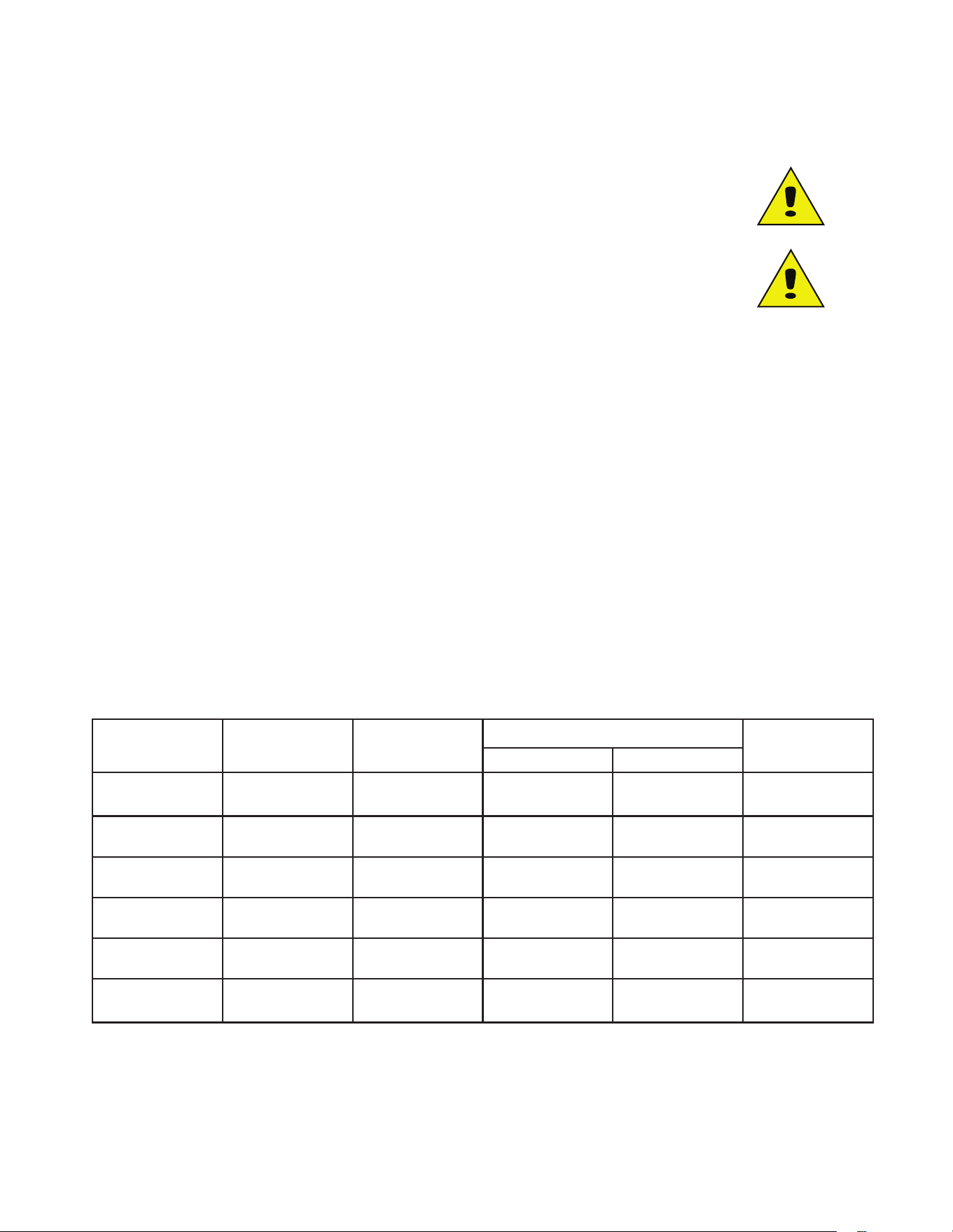
208 Volt 240 Volt 480 Volt 208 V 240 V
L1 L2 L3 L1 L2 L3 L1 L2 L3 L1 L2
Single 6.0 28.8 28.8 0 25.0 25.0 0 12.5 12.5 0 28.8 25.0
Double 12.0 50.0 28.8 28.8 43.3 25.0 25.0 21.7 12.5 12.5 57.7 50.0
Triple 18.0 50.0 50.0 50.0 43.3 43.3 43.3 21.7 21.7 21.7 86.5 75.0
PHASING
POWER
SUPPLY
TERMINAL
BLOCK
SINGLE
DECK
DOUBLE
DECK
TRIPLE
DECK
SINGLE
PHASE
L1 1 3 5
L2 2 4 6
THREE
PHASE
L1 1 4
L2 2 5
L3 3 6

10
INITIAL START UP
Prior to putting any oven into full time operation at normal cooking
temperatures, it must be thoroughly “seasoned” or dried out. Moisture
absorption in the closed spaces, in the insulation and even inside the
heating elements can cause future trouble if not properly treated.
Before the initial use of the oven, they must be thoroughly allowed to dry
out. This is done by setting the top and bottom oven switches to the “low”
position, and setting the thermostat to 350 degrees. Allow the range ovens
to saturate until all vapor and condensation has been eliminated. For best
operating results allow the ovens to thoroughly dry out. Allow 8 to 12 hours
for this process.
If the unit is out of use for three or more days, a one-hour preheat schedule
should be used, especially when exposed to high humidity and/or cool
temperatures
NOTICE:
During the first few hours of operation you may
notice a small amount of smoke coming o the
melter, and a faint odor from the smoke. This is
normal for a new melter and will disappear after the
first few hours of use.
11
OPERATION
CAUTION:
ALWAYS KEEP THE AREA NEAR THE APPLIANCE
FREE FROM COMBUSTIBLE MATERIALS.
CAUTION:
KEEP FLOOR IN FRONT OF EQUIPMENT CLEAN
AND DRY. IF SPILLS OCCUR, CLEAN IMMEDIATELY,
TO AVOID THE DANGER OF SLIPS OR FALLS.
Ovens
The ovens must be thoroughly, preheated before satisfactory baking can be
done. The ovens will not bake uniformly if not suciently preheated.
To compensate for temperature drop when loading the ovens, set the
thermostat up 50 degrees over the desired temperature. Reset thermostat
after the ovens is loaded.
The ovens may, of course, be preheated with the 3 heat switches set at a
lower position than “High”, but the time required will be proportionally
longer. After preheating, set the two 3 heat switches for proper ratio of “top”
and “bottom” heat to suit the product to be baked or roasted.
The “Roasting and Baking” oven is equipped with a removable rack. For
baking pies, bread, or for roasting operations, the rack may be placed
directly on the metal deck and the pans placed on the rack. For baking
cakes or pastries the rack should be located in the lower position provided
by the rack supports at the sides of the range and the pans placed on the
rack in this lower position.
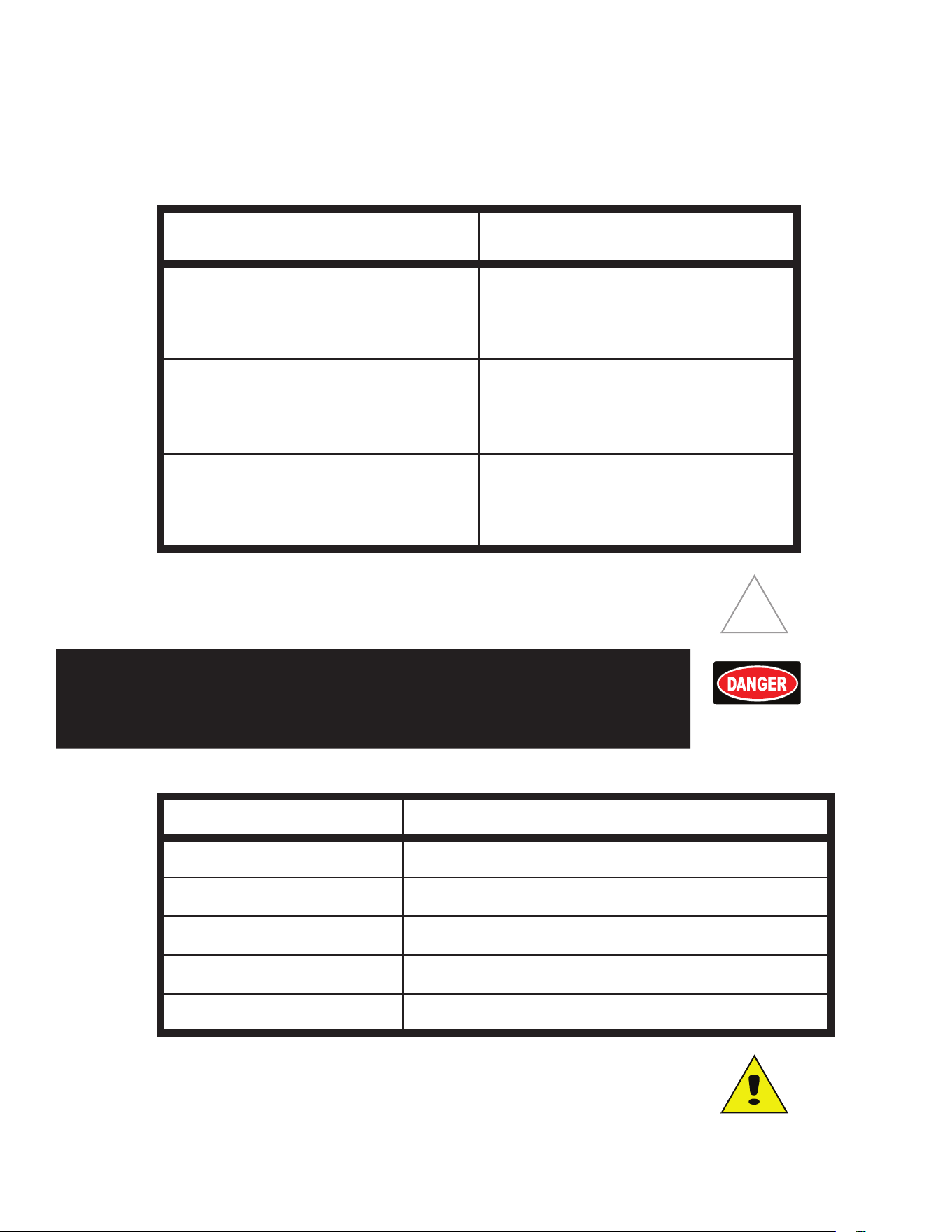
The following temperature, time, switch setting and rack positions are
suggested as a guide in baking various classes of products:
General Class
of Product
Average Range
Temperature
Time
(Min.)
With Metal Switch Settings Rack Position
Top Bottom
Pies 375-425 35-60 Low Medium "Rack on
Deck"
Rolls 375-400 15-30 Low High Rack Support
Cake 350-400 20-45 Low High Rack Support
Pastries 325-375 8-20 Low High Rack Support
Bread 425-450 25-45 Low Medium Rack on Deck
Roast Beef 300-325 Low "High or
Medium"
"Rack on
Deck"
12
CLEANING
WARNING:
KEEP WATER AND SOLUTIONS OUT OF CONTROLS.
NEVER SPRAY OR HOSE CONTROL CONSOLE, ELECTRICAL
CONNECTIONS.
CAUTION:
MOST CLEANERS ARE HARMFUL TO THE SKIN, EYES, MUCOUS
MEMBRANES AND CLOTHING. PRECAUTIONS SHOULD BE
TAKEN TO WEAR RUBBER GLOVES, GOGGLES OR FACE SHIELD
AND PROTECTIVE CLOTHING. CAREFULLY READ THE WARNING
AND FOLLOW THE DIRECTIONS ON THE LABEL OF THE
CLEANER TO BE USED.
The oven should be thoroughly cleaned at least once a week in addition to
the normal daily cleaning to insure against the accumulation of foreign
material. Keep inside of oven and metal deck clean, particularly around
door opening, door edges and at bottom of door opening so that the door
may close tightly.
NOTICE: Any oven cleaner used should be marked: “SAFE ON ALUMINUM”.
Outside of oven and top should be kept clean.
Electric equipment is inherently clean and sanitary, but may become
unsanitary if dirt is allowed to accumulate on it. Take advantage of the
clean, sanitary features of electric equipment, give it the regular attention
that it deserves the same as any other highly perfected machinery, to insure
best results and continued high operating eciency.
CALIBRATION
Calibration Check
• Place thermometer or thermocouple in the center of oven cavity.
• Set thermostat to 350° and place both 3-heat switches in the “HIGH” position.
• Allow the oven to Preheat for at least half an hour.
• Note cycle on temperatures and cycle o temperatures for 3 cycles. (Red
indicator light indicates when oven is calling for heat)
• After 3 cycles average the temperature. ( Add all six temperatures and divide by 6)
Calibration Adjustment
• A 1/16” flat blade screwdriver with a 2” shaft is required to make adjustments on the
thermostat.
• Maintain the oven temperature at 350°.
• Without turning the thermostat, remove the knob.
• Locate the adjustment screw at the base of the shaft and insert the screwdriver.
• Grasp the shaft and turn the screwdriver. Counter clockwise to increase and clockwise to
decrease (1/8 of a turn will move the temperature 5-7 ° in either direction).
• Reinstall the oven knob and recheck the oven temperature.
13
TROUBLESHOOTING
Symptoms
What follows is a chart of Symptoms, Possible Causes, and Remedy’s to
aid in diagnosing faults with the oven.
Refer to the Symptoms column to locate the type of failure then to the
Possible Cause for the items to be checked and the Remedy to column for
possible solutions.
SYMPTOM POSSIBLE CAUSE
Oven will not heat
• No power to Range
• Internal breaker tripped
• Defective Thermostat
• Defective 3-heat switch
• Defective oven element
Product is burning
• Product is cooked too long
• Failed Thermostat
• Failed 3-heat switch
Product under done
• Product is not cooking long enough
• Failed Thermostat
• Failed 3-heat switch
TESTS
NOTICE:
Service on this, or any other, LANG appliance must be performed
by qualified personnel only. Consult your authorized service agent
directory or call the factory at 800-264-7827, or www.langworld.
com for the service agent nearest you.
WARNING:
BOTH HIGH AND LOW VOLTAGES ARE PRESENT
INSIDE THIS APPLIANCE WHEN THE UNIT IS
PLUGGED/WIRED INTO A LIVE RECEPTACLE. BEFORE
REPLACING ANY PARTS, DISCONNECT THE UNIT
FROM THE ELECTRIC POWER SUPPLY.
HIGH
VOLTAGE
If an item on the list is followed by an asterisk (*), the work should be done by a factory
authorized service representative.
POSSIBLE CAUSE TEST
Product is cooked too long • No test available, operational condition
Failed Thermostat • Verify calibration
Failed element
• Remove wires and check for continuity across the
element*
Failed 3-heat switch
• Call factory or consult Service Manual for correct
checks on each switch*
Failed internal breaker • Reset breaker
CAUTION:
USE OF ANY REPLACEMENT PARTS OTHER THAN
THOSE SUPPLIED BY LANG OR THEIR AUTHORIZED
DISTRIBUTORS CAN CAUSE BODILY INJURY TO THE
OPERATOR AND DAMAGE TO THE EQUIPMENT AND
WILL VOID ALL WARRANTIES.
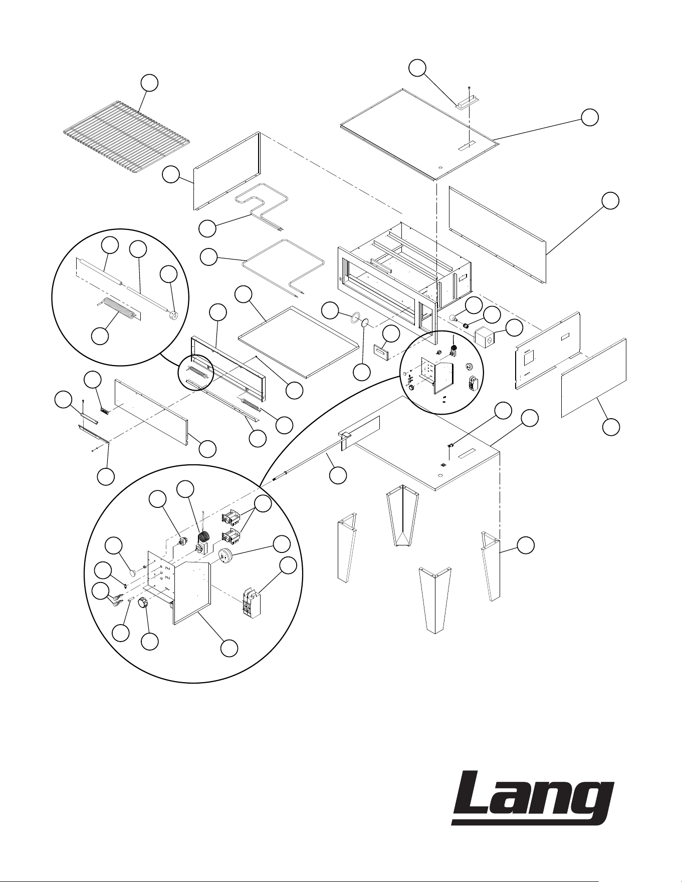
14
Model
DO54R & DO54B, 54” Deck Oven
3827, 54” Deck Oven
SK2298 REV E (07-23)
®
2
14
13
12
23
22
38
39
40
37
31
34
36
30
28
41
27
26
25
24
42
43
44
45
48
50
46
47
15
16
17
18
19
20
4
8
9
11
5
6
7
1
EXPLODED VIEW

15
IMPORTANT: WHEN ORDERING, SPECIFY VOLTAGE OR TYPE GAS DESIRED PAGE
INCLUDE MODEL AND SERIAL NUMBER OF
1
2
PARTS LIST REV D (07-23)
Some items are included for illustrative purposes only and in certain instances may not be available.
Item
No.
Part No Qty Description Application
1 N9-3827-225-1 1 S/S OVEN TOP ALL MODELS
2 N9-3827-101-10 1 BODY WRAP BACK R DECK S/S ALL ROAST MODELS
N9-3827-101-11 BODY WRAP BACK B DECK S/S ALL BAKE MODELS
4 N9-3827-101-13 1 BODY SIDE R DECK S/S - RH ALL ROAST MODELS
N9-3827-101-15 BODY SIDE B DECK S/S - RH ALL BAKE MODELS
5 2S-31603-04 1 LAMPS INC 250V 50W ALL MODELS
6 2E-31602-04 1 LAMP SKT SNAP-IN WHT PORCELAIN ALL MODELS
7 N9-3827-231-1 1 LIGHT BOX WELDMENT ALL MODELS
8 2C-20103-02 1 SCRW SM PLT 10 X .5 PHLSL TP A ALL MODELS
2C-20202-10 WSHR PLT #10 LOCK EXT ALL MODELS
8 2E-31200-02 1 LUG GROUNDING UL APPROVED ALL MODELS
9 N9-3827-103 1 BOTTOM ALL MODELS
11 9Y-LK-27 1 LEG KIT (SET OF 4) OPTIONAL ACCESSORY
9Y-LK-27M MARINE LEG KIT (SET OF 4)
12 2E-30304-W35 2 SWITCH, EGO REPLACED BY PS-60101-W3 ALL MODELS
13 2J-30801-01 1 TIMER MECHANICAL LONG ALL MODELS
14 2E-31800-01 2 CB 250V50A 1 POLE CRLNGSW
DO54B 208V AND 240V; DO54R 208V, 240V, AND
240VM
2E-31800-04 1 CIRCUIT BRK 480V 50A 3 PL
DO54B 2/3VM, 440VM, 480V AND 480VM ; DO54R
380/440/480VM
15 N9-3827-240 1 CONTROL PANEL SPOT ALL MODELS
16 Q9-70701-09-2 1 KNOB ASSY MAN TIMER, RED
Y9-70701-10 2 KNOB ASSY 3-HEAT 208-240V, BLACK
Y9-70701-10-2 KNOB ASSY 3HT 208/240, RED
Y9-70701-15 1 KNOB ASSY 550°F, BLACK
Y9-70701-15-2 KNOB ASSY 550°F, RED
17 Y9-31601-01-1 1 PILOT LT 250V W/TIN CLIP
DO54 208V, 2/3VM, AND 240V; DO54R 208V, 240V,
AND 240VM
Y9-31601-02-1 PILOT LT 480V W/TIN CLIP DO54B 480V/480VM; DO54R 380/440/480VM
18 2E-30901-02 2 FUS HLDR FOR 15AMP FUSE ALL MODELS
2E-30900-01 FUSE 15 AMP
19 2E-30303-05 1 SWT PLATE ON/OFF ALL MODELS
20 2R-70701-25 1 KNOB DAMPER BLACK PLAIN ALL MODELS
22 2E-30303-06 1 SWT TOG ON-ON DPDT BLK ALL MODELS
23 2T-30402-07 1 STAT ADJ 550o 48 C/T ALL MODELS
24 N9-3827-116 1 SWITCH DOOR - R DECK ALL ROAST MODELS
N9-3827-116-1 SWITCH DOOR - B DECK ALL BAKE MODELS
25 2S-31604-01 1 OVEN LAMP LENS (WATCH GLASS) ALL MODELS
26 2S-31604-02 1 OVEN LAMP LENS GASKET ALL MODELS
27 2C-20101-10 2 SCRW THD MS 1/4-20X2 1/4 ALL MODELS
28 N9-3827-201 2 DOOR SPREADER BAR ALL MODELS
30 N9-3827-213-3 DOOR OUTSIDE ‘B’ DECK ALL BAKE MODELS
N9-3827-213-2 DOOR OUTSIDE “R” DECK ROAST, SOLID DOOR
31 P9-50312-79 1 RANGE HANDLE ALL MODELS EXCEPT MARINE
34 2R-50800-91 1 DOOR HANDLE ALL MODELS EXCEPT MARINE
Y9-50300-38-1 HANDLE MARINE - ASSY SOLD AS 50300-38 ALL MARINE MODELS
36 K9-60301-43-1 1 SATIN CHRM-LANG DIE CAST REPLACES 2M-60301-43 ALL MODELS
37 2P-51001-01 1 SPRING OVN LH DOOR ALL MODELS
38 N9-LA36-146 2 DOOR PIPE LA36 ALL MODELS
39 N9-LA36-145 2 DOOR RODS LA36 ALL MODELS
40 2A-50800-07 2 TENSION DISC STD OVEN ALL MODELS
41 2A-50800-02 1 SPRING OVN RH DOOR ALL MODELS
42 N9-3827-204-4 1 DOOR INSIDE PANEL - R ALL ROAST MODELS
N9-3827-204-3 DOOR INSIDE PANEL - B ALL BAKE MODELS
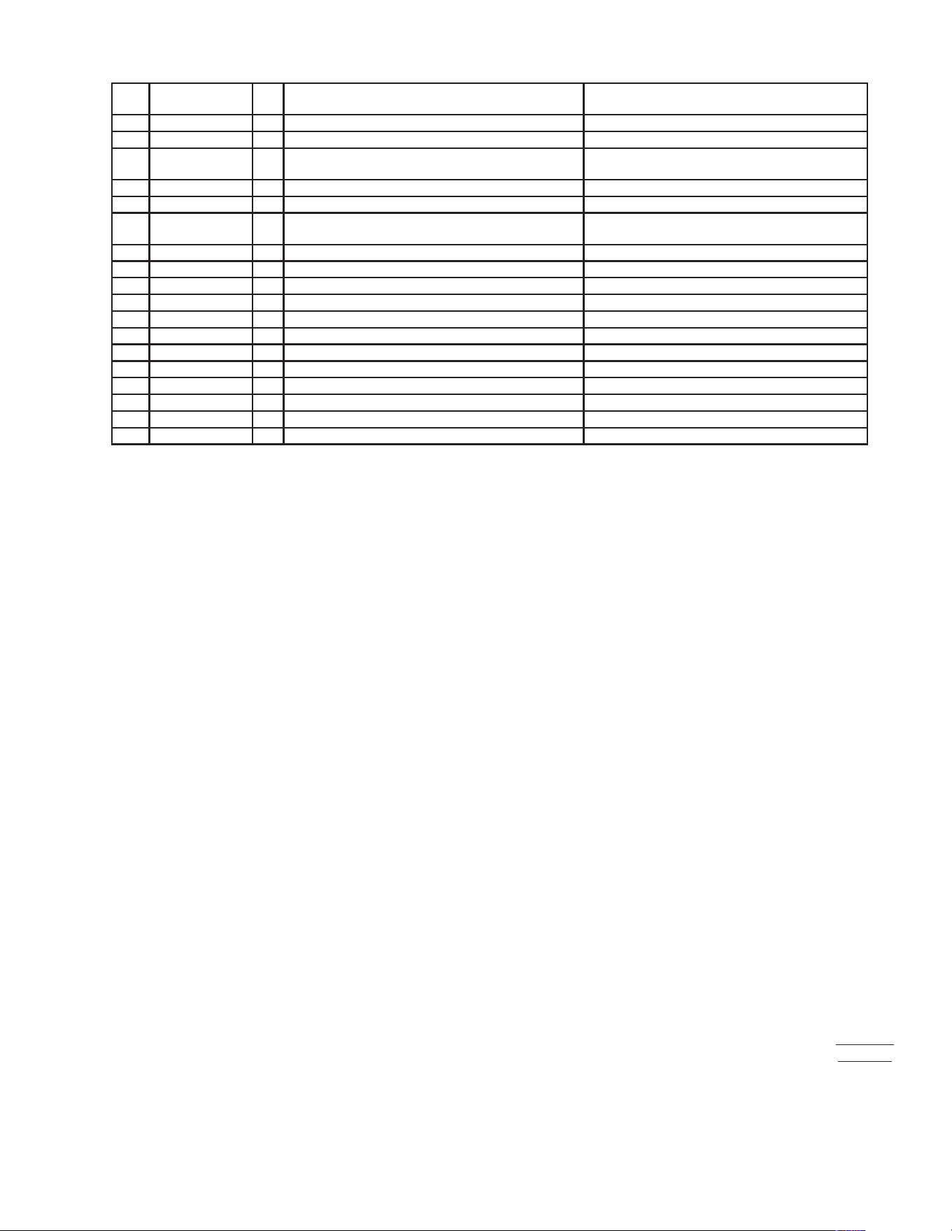
16
PARTS LIST cont. REV D (07-23)
IMPORTANT: WHEN ORDERING, SPECIFY VOLTAGE OR TYPE GAS DESIRED PAGE
INCLUDE MODEL AND SERIAL NUMBER OF
Some items are included for illustrative purposes only and in certain instances may not be available.
2
2
Item
No.
Part No Qty Description Application
43 N9-3827-222 1 METAL DECK ALL MODELS
44 2N-11070-09 2 ELMNT 3827OVEN 208V I/S 1340W ALL 208V MODELS
2N-11070-15 ELE 3827OVN 240V IS 1340W
DO54B 2/3VM AND 240V; DO54R 240V AND
240VM
2N-11070-19 ELMNT 3827OVEN 480V I/S 1340W ALL 480V MODELS
45 2N-11070-10 2 ELMNT 3827OVEN 208V O/S 1635W DO54B 208V; DO54R 208V & VM
2N-11070-16 ELE 3827OVN 240V OS 1635W
DO54B 2/3VM AND 240V; DO54R 240V AND
240VM
2N-11070-20 ELMNT 3827OVEN 480V O/S 1635W ALL 480V MODELS
46 N9-3827-101-12 1 BODY SIDE R DECK S/S - LH ALL ROAST MODELS
N9-3827-101-14 BODY SIDE - B DECK S/S- ALL BAKE MODELS
47 2B-50200-11 1 RACK 3827R DECK ALL ROAST MODELS
2B-50200-12 RACK 3827B DECK ALL BAKE MODELS
48 N9-3827-721-1 1 VENT COVER WELD ALL MODELS
50 N9-3827-W722 1 DAMPER & ROD WELDMENT ALL MODELS
NI N9-3827-711-3 1 DOOR ASSY R DECK W/OUT WINDOW DO54R
NI N9-3827-711-2 1 DOOR ASSY B DECK W/OUT WINDOW DO54B
NI N9-3827-800 1 DOOR ASSY R DECK W/OUT WINDOW MARINE DO54R MARINE
NI N9-3827-711-2-0 1 DOOR ASSY MRN B DECK W/ OUT WINDOW DO54B MARINE
NI 2E-31400-04 1 TRANSFORMER 480/240VAC 100VA ALL 480V MODELS
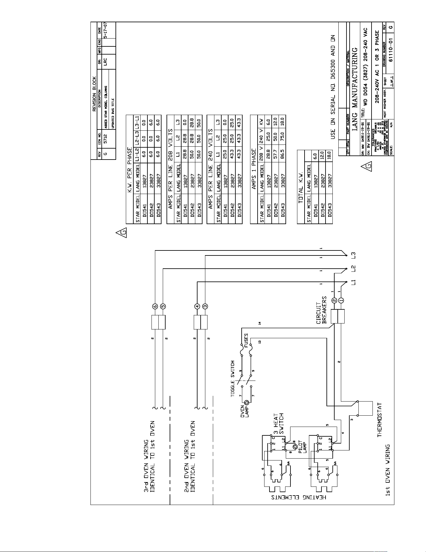
17
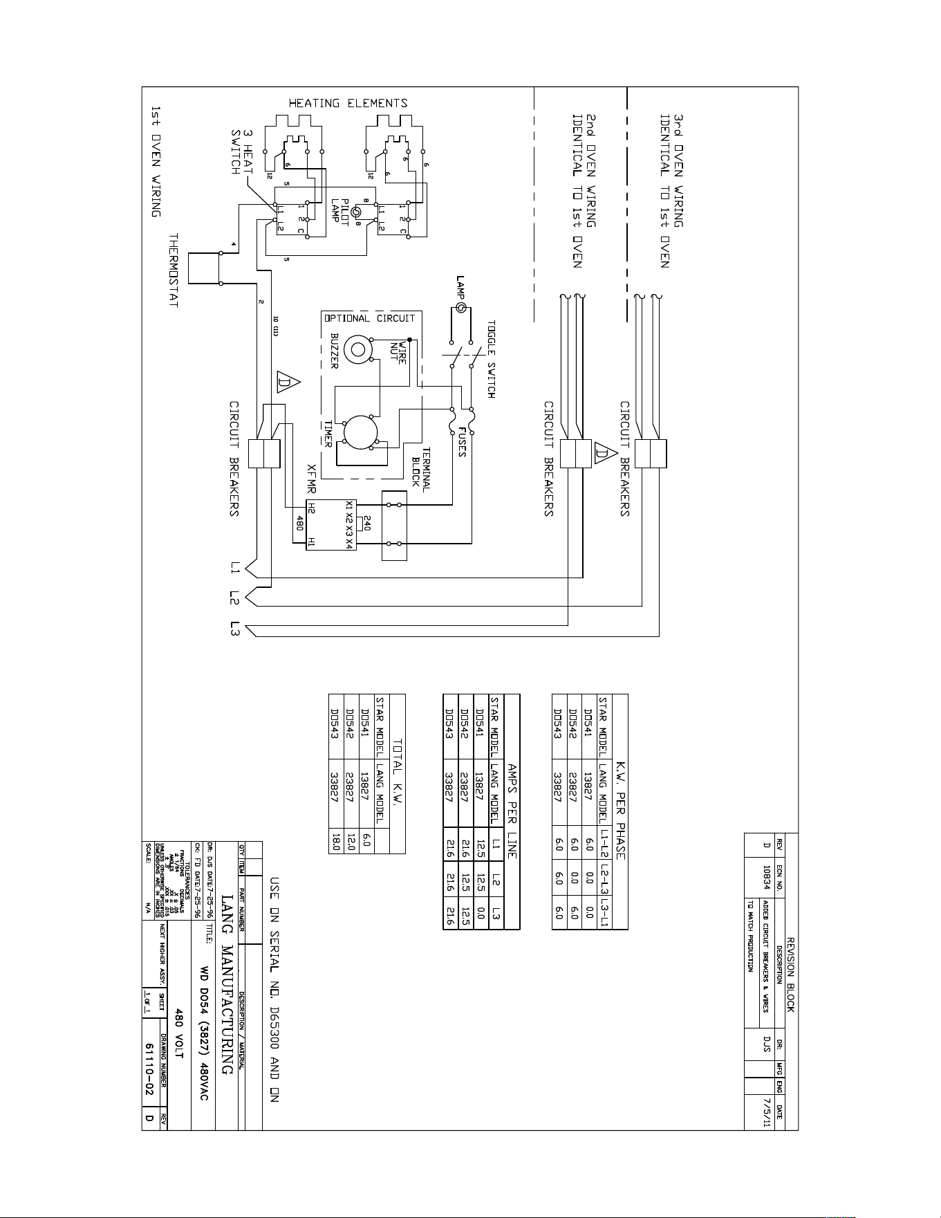
18
19
LANG_WARRANTY 2023 FINAL v2
LIMITED EQUIPMENT WARRANTY
Lang Manufacturing warrants to the original purchaser of new Lang
products to be free from defects in material or workmanship, under normal
and proper use and maintenance service as specified by Lang and upon
proper installation and start-up in accordance with the instructions
supplied with each Lang unit. Lang’s obligation under this warranty is
limited to a period of one [1] year beginning from the date of original
installation. The warranty period begins upon the earlier of the date of
original installation or up to six [6] months after the original shipment, from
the factory, of the covered product. Defects that occur as a result of normal
use, within the time period and limitations defined in this warranty, will at
Lang’ discretion have the parts replaced or repaired by Lang or a Lang-
authorized service agency.
THIS WARRANTY IS SUBJECT TO ALL LISTED CONDITIONS
Repairs performed under this warranty are to be performed by a Lang
authorized service agency. Lang will not be responsible for charges incurred
or service performed by non-authorized repair agencies. In all cases, the
nearest Lang-authorized service agency must be used. Lang will be
responsible for normal labor charges incurred in the repair or replacement
of a warrantied product within 50 miles (80.5 km) of an authorized service
agency. Time and expense charges for anything beyond that distance will
be the responsibility of the owner. All labor will need to be performed
during regular service hours. Any overtime premium will be charged to the
owner. For all shipments outside the U.S.A. and Canada, please see the
International Warranty for specific details. It is the responsibility of the
owner to inspect and report any shipping damage claims, hidden or
otherwise, promptly following delivery. No mileage or travel charges will be
honored on any equipment that is deemed portable. In general, equipment
with a cord and plug weighing less than 50 lb. (22.7 kg) is considered
portable and should be taken or shipped to the closest authorized service
agency, transportation prepaid.
CONTACT
Should you require any assistance regarding the operation or maintenance
of any Lang Manufacturing; phone or email our service department. In all
correspondence provide the model number and serial number of the unit
needing service; include the voltage or gas type.
Normal Business Hours: 8:00 a.m. to 4:30 p.m. Central
Telephone: 800-264-7827 Tech Service Option 2
Email: TechService@partstown.com
www.LangWorld.com
PRODUCTS
PARTS
LABOR
Lang Strato Series™
convection ovens
2 years 2 years
Lang convection oven doors
(excluding hardware)
lifetime 2 years
Lang griddles 2 years 2 years
Chrome griddle surfaces
[against peeling]
5 years
Cast iron grates, burners
and burner shields
1 year
Original Lang parts sold to repair
Lang equipment
90 days
Lang Ranges 2 years 2 years
Lang Marine 2 years 2 years
WARRANTY EXCLUSIONS
THE FOLLOWING WILL NOT BE COVERED UNDER WARRANTY.
Lang’s sole obligation under this warranty is limited to either repair or
replacement parts, subject to the additional limitations detailed
below. This warranty neither assumes nor authorizes any person to
assume obligations other than those expressly covered by this
warranty.
• Any product which has not been used, maintained, or installed in
accordance with the directions published in the appropriate
installation sheet and/or owner’s manual, including incorrect gas or
electrical connection. Lang is not liable for any unit which has been
mishandled, abused, misapplied, subjected to harsh chemicals,
modified by unauthorized personnel, damaged by flood, fire, or other
acts of nature [or God], or which have an altered or missing serial
number.
• Installation, labor, and job checkouts, calibration of heat controls,
air and gas burner/bypass/pilot adjustments, gas or electrical system
checks, voltage and phase conversions, cleaning of equipment, or
seasoning of griddle surface.
• Replacement of fuses or resetting of circuit breakers, safety
controls, or reset buttons.
• Replacement of broken or damaged glass components, quartz
heating elements, and light bulbs.
• Labor charges for all removable and consumable parts in gas
charbroilers and hotplates, including but not limited to burners,
grates, and radiants.
• Any labor charges incurred by delays, waiting time, or operating
restrictions that hinder a service technician’s ability to perform
service.
• Replacement of parts that fail or are damaged due to normal wear
or labor for replacement of parts that can be replaced during a daily
cleaning routine, such as but not limited to silicone belts, PTFE non-
stick sheets, control labels, knobs, bulbs, fuses, quartz heating
elements, baskets, racks, and grease drawers.
• Any economic loss of business or profits.
• Non-OEM parts. Use of non-OEM parts without Lang’s approval will
void the warranty.
• Components that should be replaced when damaged or worn, but
have been field-repaired instead [e.g. field-welded fry pots]
• Units exceeding one [1] year from original installation date.
ADDITIONAL WARRANTIES
• Specific/chain-specific equipment may have additional and/or
extended warranties.
The foregoing warranty is in lieu of any, and all other warran�es
expressed or implied and cons�tutes the en�re warranty.

STAR INTERNATIONAL HOLDINGS INC. COMPANY
Star - Holman - Lang - Wells - Toastmaster
265 Hobson St, Smithville, TN 37166 U.S.A.
(800) 264-7827
www.star-mfg.com