
C
COVER
WR315GR-2C-LTE6-GAX-EC
Industrial Secure Cellular Router, 2C (Dual Core), WLAN 6 + LTE 6-G, EC OS
EC OS Web interface and SSH commands
Jun.2026 V1.3e
Original version:
WR315GR-M2 Series
Industrial Secure Cellular Router, 2C (Dual Core) Series

2
WoMaster
WR315GR –M2 Series
WR315GR-2C-LTE6-GAX-EC
Industrial Secured Cellular Router, 2C (Dual Core) Series
User Manual
Copyright Notice
© WoMaster. All rights reserved.
About This Manual
This user manual is intended to guide a professional installer to install and to configure the WoMaster
Industrial Secured and Rugged LTE Serial Router. It includes procedures to assist you in avoiding
unforeseen problems.
NOTE:
Only qualified and trained personnel should be involved with installation, inspection, and repairs of this
router.
Disclaimer
WoMaster reserves the right to make changes to this Manual or to the product hardware at any time without notice.
Information provided here is intended to be accurate and reliable. However, it might not cover all details and
variations in the equipment and does not claim to provide for every possible contingency met in the process of
installation, operation, or maintenance. Should further information be required or should particular problem arise
which are not covered sufficiently for the user’s purposes, the matter should be referred to WoMaster. Users must be
aware that updates and amendments will be made from time to time to add new information and/or correct
possible unintentional technical or typographical mistakes. It is the user’s responsibility to determine whether there
have been any such updates or amendments of the Manual. WoMaster assumes no responsibility for its use by the
third parties.
WoMaster Online Technical Services
At WoMaster, you can use the online service forms to request the support. The submitted forms are stored in server
for WoMaster team member to assign tasks and monitor the status of your service. Please feel free to write
to help@womaster.eu if you encounter any problems.

3
TABLE OF CONTENTS
COVER .............................................................................................................................................................................. 1
TABLE OF CONTENTS ....................................................................................................................................................... 3
DECLARATION OF CONFORMITY ..................................................................................................................................... 5
SAFETY PRECAUTION ..................................................................................................................................................... 10
1. INTRODUCTION ........................................................................................................................................................ 12
1.1 OVERVIEW ............................................................................................................................................. 12
1.2 MAJOR FEATURES ................................................................................................................................... 13
2. HARDWARE INSTALLATION ....................................................................................................................................... 14
2.1 HARDWARE DIMENSION ........................................................................................................................ 14
2.2 INSTALLATION ........................................................................................................................................ 17
2.3 WIRING THE POWER INPUTS ................................................................................................................... 17
2.4 WIRING THE ALARM RELAY OUTPUT (DO) ................................................................................................ 18
2.5 CONNECTING THE GROUNDING SCREW ................................................................................................... 18
2.6 DIN RAIL MOUNTING .............................................................................................................................. 19
2.7 OPTIONAL ANTENNA ................................................................................................................................. 20
2.8 SIM CARD INSTALLATION ......................................................................................................................... 23
2.9 HARDWARE WATCHDOG ......................................................................................................................... 25
2.10 LED INDICATION ................................................................................................................................... 26
3. WR315G-2C-LTE6-GAX-EC EC OS INTRODUCTION .................................................................................................... 27
3.1 EC OS SOFTWARE SPECIFICATION: ................................................................................................................... 27
3.2 WR315G-2C-LTE6-GAX-EC QIG ................................................................................................................. 28
3.3 PREPARATION FOR MANAGEMENT ............................................................................................................... 34
3.4 LUCI WEB MANAGEMENT ............................................................................................................................. 38
3.4.1 STATUS ................................................................................................................................................. 38
3.4.2 SYSTEM ................................................................................................................................................. 44
3.4.2.1 System → System ............................................................................................................................... 44
3.4.2.2 System → Administration ................................................................................................................... 45
3.4.2.3 System → Flash Operation ................................................................................................................. 46
3.4.2.4 System → Reboot ............................................................................................................................... 50
3.4.2.5 Advanced Settings:............................................................................................................................. 51
3.4.3 Network ................................................................................................................................................ 52
3.4.3.1 Interfaces ........................................................................................................................................... 52
3.4.3.2 Wireless(Wi-Fi) ................................................................................................................................... 58
3.4.4.3 Routing .............................................................................................................................................. 62

4
3.4.4.4 DHCP and DNS ................................................................................................................................... 63
3.4.4.5 Diagnostics ........................................................................................................................................ 65
3.4.4.5 Firewall .............................................................................................................................................. 66
3.4.4 Services/Watchcat ................................................................................................................................ 70
3.4.5 VPN ....................................................................................................................................................... 71
4. SSH Management ...................................................................................................................................... 72
4.1 LOGIN THE ROUTER THROUGH SSH .................................................................................................................. 72
4.2 MAJOR OPENWRT CLI ................................................................................................................................ 75
4.2.1 CLI - Cellular .......................................................................................................................................... 75
4.2.2 CLI– lan ................................................................................................................................................. 79
4.2.3 CLI – WIFI(Wireless) .............................................................................................................................. 80
4.3 CUSTOMIZED CLI & SCRIPT ............................................................................................................................ 83
4.3.1 Get Information Script: wr-info-get.sh .................................................................................................. 83
4.3.2 Wireless Operation Mode Script: wr-wireless-mode.sh ......................................................................... 87
4.3.3.1 Network Ping Alarm ........................................................................................................................... 88
4.3.3.2 Hardware Condition Alarm ................................................................................................................ 90
4.3.3.3 Reading Alarm Status ........................................................................................................................ 93
4.4 FIRMWARE UPGRADE ................................................................................................................................... 94
4.5 CONFIGURATION BACKUP/RESTORE .................................................................................................................. 98
4.6 RESET TO DEFAULT ...................................................................................................................................... 99
5. REVISION HISTORY .................................................................................................................................................. 100

5
Declaration of Conformity
CE RED (Radio Device Directive)
While you see the CE Marking print in our product, it indicates the product comfort to the
requirement of the CE RED.
We provide the CE RED Declaration of Conformity (DoC) for our Wireless Router products in our
web site. The DoC includes the Brand Name, Product Name, Model Name, Description, compliant
standards and Manufacture information. Different product may comfort to different standards of
Safety, Health, EMC, Radio and other specific standard. You can download the formal document
of the product in our Web site or apply from our Sales/Technical people.
The DoC in this product manual applied to below models:
Brand Name: WoMaster
Product Name: Industrial Grade Dual-Core Secure 5GNR/LTE Router
Model Name: WR315GR-2C-M2
Serial Model Name: WR315GR-2C-5GM2-EU, WR315GR-2C-5GM2-GL,
WR315GR-2C-LTE6-GAX-EC, WR315GR-2C-LTE6, WR315GR-2C-LTE
Compliant Standard:
Safety: EN IEC 62368-1
EMC: EN301489-1/17/52, EN50121-4
MPE: EN IEC 62311
RF(By Module): EN301908-1/2/13, EN300328, EN301893
The declaration of CE RED is authorized at the following company and address.
WoM ASIA CO., LTD
( Manufacturer Name )
13F, No.190, Sec.2, Zhongxing Rd., Xindian Dist., New Taipei 231, Taiwan
( Manufacturer Address )

6
I. U.S. Federal Communications Commission (FCC)
Model Name: WR315GR-2C-LTE6-GAX-EC
FCC ID: 2AXAMWR315GM2
Contains ID: 2AXAM8XM0004
FCC Part 15 Compliance
This device complies with FCC Rules Part 15. Operation is subject to the following two conditions:
• This device may not cause harmful interference.
• This device must accept any interference received, including interference that may cause undesired
operation.
FCC Caution
Any changes or modifications not expressly approved by the party responsible for compliance could void
the user‘s authority to operate the equipment. The antenna(s) used for this transmitter must not be
co-located or operating in conjunction with any other antenna or transmitter.
Class A Digital Device Notice
Note: This equipment has been tested and found to comply with the limits for a Class A digital device,
pursuant to part 15 of the FCC Rules. These limits are designed to provide reasonable protection against
harmful interference when the equipment is operated in a commercial environment. This equipment
generates, uses, and can radiate radio frequency energy and, if not installed and used in accordance with
the instruction manual, may cause harmful interference to radio communications. Operation of this
equipment in a residential area is likely to cause harmful interference in which case the user will be
required to correct the interference at his own expense.
FCC RF Exposure Compliance
This equipment complies with FCC RF radiation exposure limits set forth for an uncontrolled environment.
End users must follow the specific operating instructions for satisfying RF exposure compliance. To
maintain compliance with FCC RF exposure compliance requirement, please follow operation instruction
as documented in this manual.
Radiation Exposure Statement:
This equipment must be installed and operated in accordance with provided instructions and the
antenna(s) used for this transmitter must be installed to provide a separation distance of at least 20 cm
from all persons and must not be co-located or operating in conjunction with any other antenna or
transmitter

7
II. Innovation, Science and Economic Development Canada (ISED)
ISED (IC Certification Information)
English
Français (French)
Model: WR315GR-2C-LTE6-GAX-EC
Modèle: WR315GR-2C-LTE6-GAX-EC
Contains Transmitter Module IC ID: 34378-WR315GRLTE6, 34378-WR315GRGAX
Industry Canada ICES-003 Compliance:
This Class A digital apparatus complies with Canadian ICES-003. CAN ICES-003 (A)/NMB-003 (A)
Avis de conformité à la réglementation d'Industrie Canada : Cet appareil numérique de la classe A est
conforme à la norme NMB-003 du Canada.
ISED Compliance Statement
English (ISED Standard Statement)
Français (Déclaration ISED Standard)
This device contains licence-exempt
transmitter(s)/receiver(s) that comply with
Innovation, Science and Economic
Development Canada's licence-exempt RSS
standard(s). Operation is subject to the
following two conditions: (1) this device may
not cause interference, and (2) this device
must accept any interference, including
interference that may cause undesired
operation of the device.
L’émetteur/récepteur exempt de licence
contenu dans le présent appareil est conforme
aux CNR d’Innovation, Sciences et
Développement économique Canada
applicables aux appareils radio exempts de
licence. L’exploitation est autorisée aux deux
conditions suivantes : (1) l’appareil ne doit pas
produire de brouillage; (2) l’appareil doit
accepter tout brouillage radioélectrique subi,
même si le brouillage est susceptible d’en
compromettre le fonctionnement.
ISED RF Exposure Compliance (RSS-102)
English
Français
This equipment complies with ISED RSS-102
radiation exposure limits set forth for an
uncontrolled environment. This equipment
should be installed and operated with
minimum distance 20 cm between the
radiator and your body.
Cet équipement est conforme aux limites
d'exposition aux radiations ISED CNR-102
établies pour un environnement non contrôlé.
Cet équipement doit être installé et utilisé
avec une distance minimale de 20 cm entre le
radiateur et votre corps.
Transmitter Antenna Information (RSS-Gen Section 6.8)
This radio transmitter IC: 34378-WR315GRLTE6, 34378-WR315GRGAX has been approved by Innovation, Science and
Economic Development Canada to operate with the antenna types listed below, with the maximum permissible gain
indicated for each antenna type. Antenna types not included in this list, having a gain greater than the maximum gain

8
indicated for any type listed, are strictly prohibited for use with this device.
Français
Le présent émetteur radio IC: 34378-WR315GRLTE6, 34378-WR315GRGAX a été approuvé par Innovation, Sciences et
Développement économique Canada pour fonctionner avec les types d’antenne énumérés ci-dessous et ayant un gain
admissible maximal pour chaque type d’antenne. Les types d’antenne non inclus dans cette liste et dont le gain est
supérieur au gain maximal indiqué pour tout type figurant sur la liste sont strictement interdits pour l’exploitation de
cet appareil.
Model
Frequency Band
Antenna type
Max gain(dBi)
Note
WR315GR-2C-LTE6-GA
X-EC
Wi-Fi 2400-2500 MHz/
5150–5850 MHz (see note)
Dipole
4.4/
5.0
Tri-band-P1/
Tri-band-P4
LTE 617-960 MHz/
1710-2700 MHz
Dipole
4.1
6.9
LTE-P2,P4/
LTE-P1
Note: Although the antenna datasheet specifies a frequency range of 5150–7125 MHz, the device's transmitter is
firmware-locked to operate strictly within the 5150–5850 MHz band. Remarque : Bien que la fiche technique de
l'antenne indique une plage de fréquences de 5150 à 7125 MHz, l'émetteur de l'appareil est verrouillé par
micrologiciel pour fonctionner uniquement dans la bande 5150 à 5850 MHz.
III. Operation and Installation Restrictions
5 GHz Operation Restriction (FCC §15.407(e) / RSS-247 §6.4)
English (Mandatory Restriction)
Français (Restriction Obligatoire)
Operation in the band 5150–5350 MHz is
restricted to indoor use only.
L'exploitation de la bande 5150-5350 MHz est
limitée à une utilisation à l'intérieur
seulement.
Installer Compliance Responsibility (KDB 353028 D01 Compliant)
Model WR315GR-2C-LTE6-GAX-EC is restricted to professional installation only.
Professional Installation Requirement: This device is restricted to Professional Installation only.
1. Distribution Channel: The equipment is intended for industrial and commercial applications and is marketed
and sold only through authorized distributors and system-integrator partners; it is not sold through general
retail channels or directly to the general public.
2. Installation Expertise: Installation and configuration must be performed by trained professional installers who
are familiar with RF planning and local regulatory requirements.
3. Antenna Restriction:
- Any antenna substitution or replacement must be performed by a professional installer.
- The professional installer is responsible for ensuring that the chosen antenna type and gain, when combined
with the device's output power settings, results in an Equivalent Isotropically Radiated Power (EIRP) that
remains compliant with local FCC and ISED regulatory limits.
- End-users are prohibited from replacing the antenna or adjusting antenna-related configuration parameters.

9
4. Installer Responsibility: The professional installer is responsible for ensuring that the device is operated in
accordance with local country regulatory requirements, including antenna selection, output power settings,
and permitted operating frequency bands.
5. End-User Control Restriction: End-users do not have access to controls that could change the operational
parameters of the device (such as antenna gain or output power) that would violate FCC and ISED regulatory
compliance.
Le modèle WR315GR-2C-LTE6-GAX-EC est réservé à une installation professionnelle.
Exigence d'installation professionnelle : Cet appareil est limité à une installation
professionnelle uniquement.
1. Canal de distribution (Distribution Channel) : L'équipement est destiné aux applications industrielles et
commerciales et est commercialisé et vendu uniquement par l'intermédiaire de distributeurs agréés et de
partenaires intégrateurs de systèmes ; il n'est pas vendu par les canaux de vente au détail généraux ni
directement au grand public.
2. Expertise en installation (Installation Expertise) : L'installation et la configuration doivent être effectuées par des
installateurs professionnels formés qui connaissent la planification des radiofréquences (RF) et les exigences
réglementaires locales.
3. Restriction relative à l'antenne (Antenna Restriction) :
⚫ Toute substitution ou remplacement d'antenne doit être effectué par un installateur professionnel.
⚫ L'installateur professionnel est responsable de s'assurer que le type d'antenne et le gain choisis,
lorsqu'ils sont combinés aux réglages de puissance de sortie de l'appareil, entraînent une puissance
isotrope rayonnée équivalente (PIRE) qui reste conforme aux limites réglementaires locales de la FCC et
de l'ISDE.
⚫ Il est interdit aux utilisateurs finaux de remplacer l'antenne ou de modifier les paramètres de
configuration liés à l'antenne.
4. Responsabilité de l'installateur (Installer Responsibility) : L'installateur professionnel est responsable de s'assurer
que l'appareil est utilisé conformément aux exigences réglementaires du pays local, y compris la sélection de
l'antenne, les réglages de puissance de sortie et les bandes de fréquences de fonctionnement autorisées.
5. Restriction du contrôle par l'utilisateur final (End-User Control Restriction) : Les utilisateurs finaux n'ont pas
accès aux commandes qui pourraient modifier les paramètres opérationnels de l'appareil (tels que le gain de
l'antenne ou la puissance de sortie) qui violeraient la conformité réglementaire de la FCC et de l'ISDE.
10
SAFETY PRECAUTION
⚫ Statement regarding restricted access: The equipment is intended to be used in a restricted access
location. Access should only be given to skilled person or instructed person who has been trained in the
operation of the equipment and informed of the potential hazards.
⚫ Power Specification: Follow the power installing instruction of the user manual, it indicates the available input
voltage range, V+/V- pin assignment, power consumption and other notice. Only operate the device within the
specified input voltage range as indicated in the user manual and the device label.
⚫ Disconnect Device: A readily accessible disconnect device (such as a circuit breaker or switch) shall be
incorporated in the building installation wiring for permanently connected equipment.
⚫ Overcurrent Protection: To ensure protection against short circuits and fire hazards in the supply circuit, it is
recommended to install an external fuse or circuit breaker rated at 2A (for 24V) or 3A (for 12V) on the power
input line.
⚫ Switch ON Notice: Only switch on the supply voltage after verifying that the housing is closed, the input
voltage is correct, and the terminal blocks are wired correctly.
⚫ Grounding: To avoid system damage, the equipment should be connected to ground. Reliable grounding is
essential for EMC compliance and safety. Ensure the equipment is properly connected to the protective earth
(PE) ground before connecting the power supply. Use a grounding wire with a minimum cross-sectional area of
18 AWG. For better EMC performance (noise immunity), a thicker and shorter grounding wire is recommended.
⚫ Wiring: Use connection cables that are rated for the specified voltage, current, wire diameter, and temperature
range. For reliable data transmission in harsh environments, use high-quality industrial-grade RJ45 connectors
to prevent signal loss or intermittent connection.
Note for PoE application (if used): If the equipment is installed in a PoE (Power over Ethernet) environment
(e.g., using a PoE splitter), use high-quality industrial-grade RJ45 connectors. In harsh environments, inferior
quality plugs may cause arcing, short circuits, or damage to the PD (Powered Device).
⚫ Hot Surface Warning: Caution: The metal housing may become very hot during operation (especially when
PoE power is supplied), avoid touching the surface directly. Allow the equipment to cool down before handling
or maintenance.

11
⚫ Mounting: The equipment is only suitable for mounting at height ≦2m.
⚫ Environment: Only operate the device at the specified ambient temperature and humidity. Do not expose the
device to rain or moisture unless it is rated for such environments.
⚫ SIM Card: Caution: Disconnect the power supply before removing the SIM cover or inserting/removing
the SIM card.
⚫ SIM Card: Ensure that the SIM card is installed correctly to avoid damage to the SIM card or the router.
The SIM cover must be mounted again before power is reapplied.
⚫ NOT allow to open the housing: There are no user-serviceable parts inside. Only technicians authorized by the
manufacturer are permitted to service the equipment.

12
1. INTRODUCTION
1.1 OVERVIEW
New industrial high-performance router WR315GR-M2 Series with dual-core 880MHz CPU has
a M2 expansion socket for 5GNR Cellular as well as 4G LTE, 3G/2G networks. One Gigabit WAN
port and four Gigabit LAN ports provide switch functions as well as WAN redundancy upon cellular
networks.
The WR315GR-2C-LTE6-GAX-EC series supports LTE Cat.6 and Wi-Fi 6 for cellular and
Wireless LAN connectivity and latest OpenWRT operating system.
Model Name
Description
WR315GR-M2
Industrial Secure Router,
Dual Core
, 5GbE, 1 Relay, 2SIM, 1x Expansion M2 socket
WR315GR-2C-LTE6-G-EC
Industrial Secure Router, Dual Core, 5GbE, 1 Relay, EC OS, LTE6-G
WR315GR-2C-LTE6-GAX-EC
Industrial Secure Router, Dual Core, 5GbE, 1 Relay, EC OS, 802.11ax WLAN6 client,
LTE6-G
EC OS: Embedded Computing based on OpenWRT OS.
Note: The web GUI/SSH command is different than standard WOM OS version, it
supports one SIM only.
5GNR/LTE Frequency/Bands:
*choose one by region: For other frequency bands not listed, please inquire with our sales.
List the available 4G LTE module/region in below
*1/2 Serial Port support by request, please inquire with our sales.
© WoMaster Inc. All rights reserved. Specifications are subject to change without notice. Please ask our sales for the most up-to-date
product information.

13
1.2 MAJOR FEATURES
Below are the major features of WR315GR-2C-LTE6-GAX-EC:
- Dual Core High Speed Processor
- 5 x 100/1000MBase-T RJ45, Auto Negotiation, supports routing mode with 1xWAN and 4xLAN ports
- Extended M2 socket for 4G LTE Cat.6, up to 300Mbps DL speed, backward compatible with 3G
- Supports Wi-Fi 6 Client WAN connectivity, 2.4G/5GHz Wi-Fi 6 station with up to 1800Mbps peak rate
- Support Nano SIM for 4G LTE connectivity
- The EC OS version software supports LTE Cat.6 Global band + Wi-Fi 6 Client mode (Mode with LTE6-GAX-EC)
◼ Features: OpenWRT 23.05, Router mode of 1xWAN+4xLAN, SSH terminal, LuCI web GUI includes System
Setting, NTP Setting, Router Password setting with strength check, SSH Access and Key upload, HTTPS,
init script startup setting, configuration backup/restore, firmware upgrade, system reboot,
watchcat(watchdog), ser2net, Interface configuration, Wi-Fi interface setting, DHCP server/client, DHCP
Relay, DNS, firewall setting, static router, Diagnostic Ping, traceroute, Nslookup, Device Status and
Mobile Information.
◼ WLAN Configuration: Support Wi-Fi Client mode.
WLAN Basic Settings: Radio on/off, mode selection, 2.4G/5G 11ax Band and Frequency selection, SSID,
Hide SSID, Wireless Security encryption includes WPA3-SAE and WPA2-PSK/WPA-PSK/Open, advanced
WLAN settings, WLAN MAC Filter, 802.11r fast transition
◼ Cellular Configuration: Support Modem manager tool for Radio on/off, 4G LTE/3G HSPA Configuration,
APN, SIM Security, Connection Status and Cellular diagnostic
- Steel Metal Housing and aluminum heat sinks inside for heat dissipation
- Wide range operating temperature -40~70˚C
- Typical 24V (9-48V) power input
- IP30 ingress protection
14
2. HARDWARE INSTALLATION
This chapter introduces hardware and contains information on installation and configuration procedures.
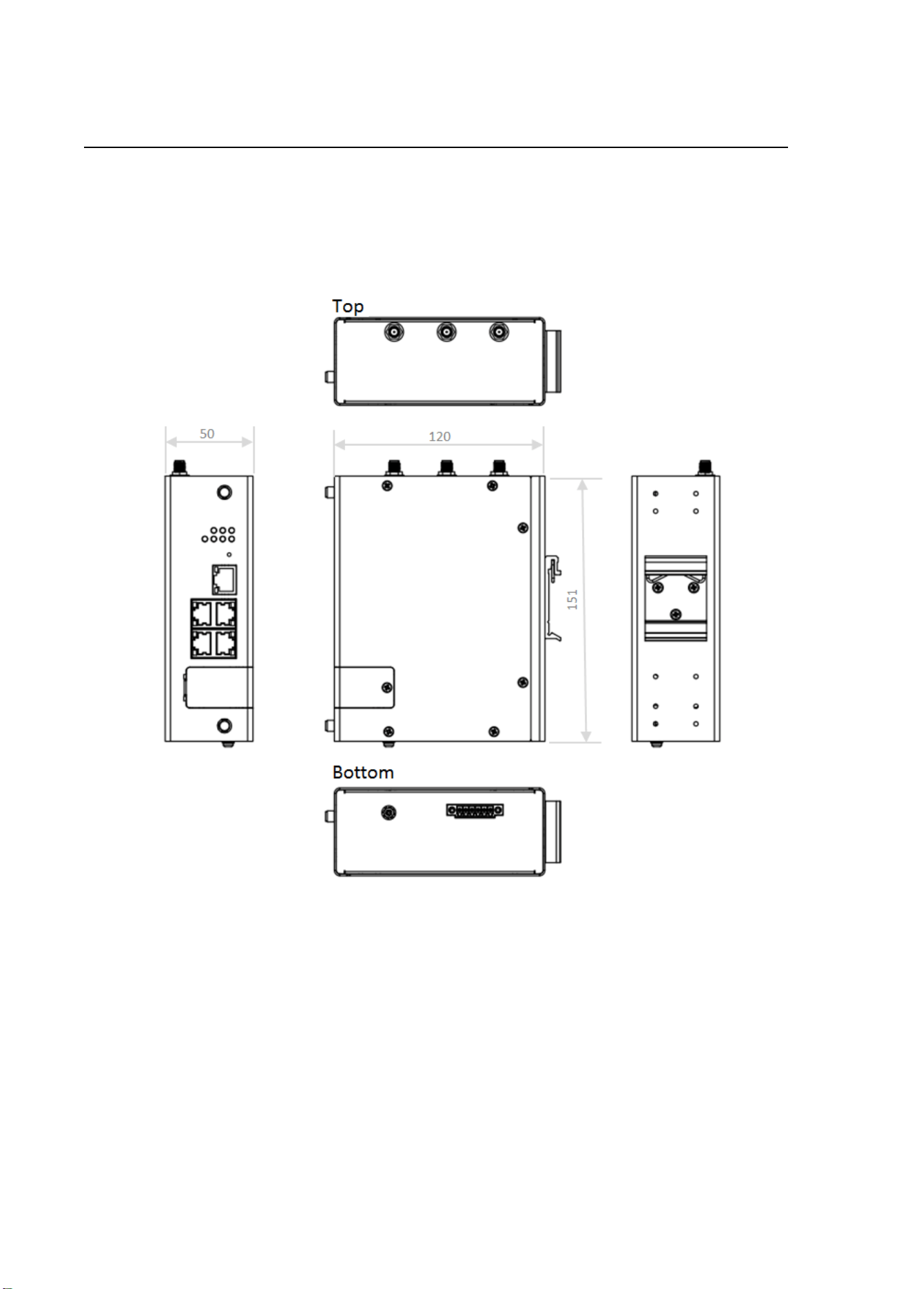
2.1 HARDWARE DIMENSION
Dimensions of WR315GR-M2: 50 x 151 x 120 (W x H x D) / without DIN Rail Clip
15
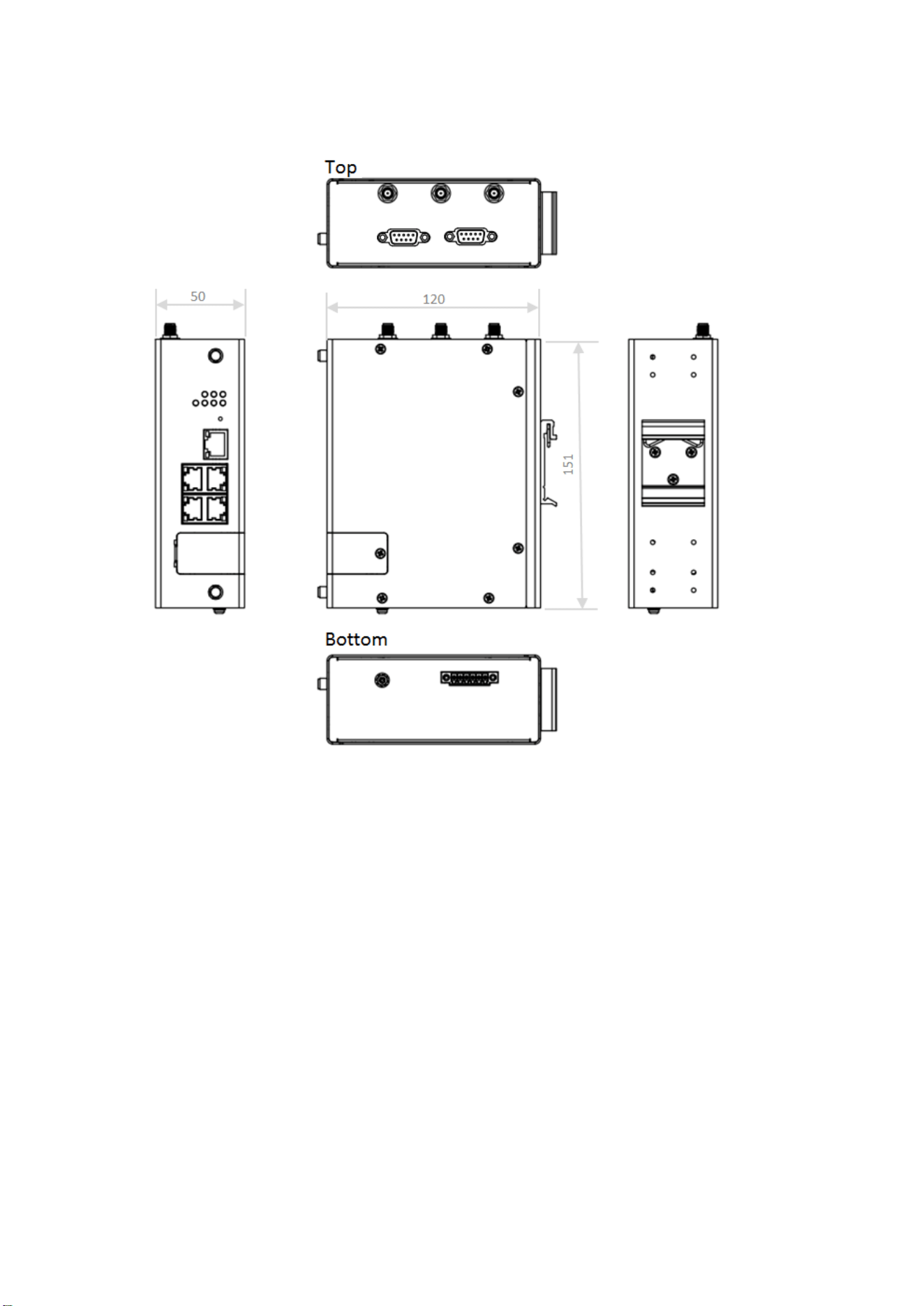
Dimensions of WR315GR-M2+2COM: 50 x 151 x 120 (W x H x D) / without DIN Rail Clip
(Model with 1 or 2 Serial ports)
16
Front Panel Layout
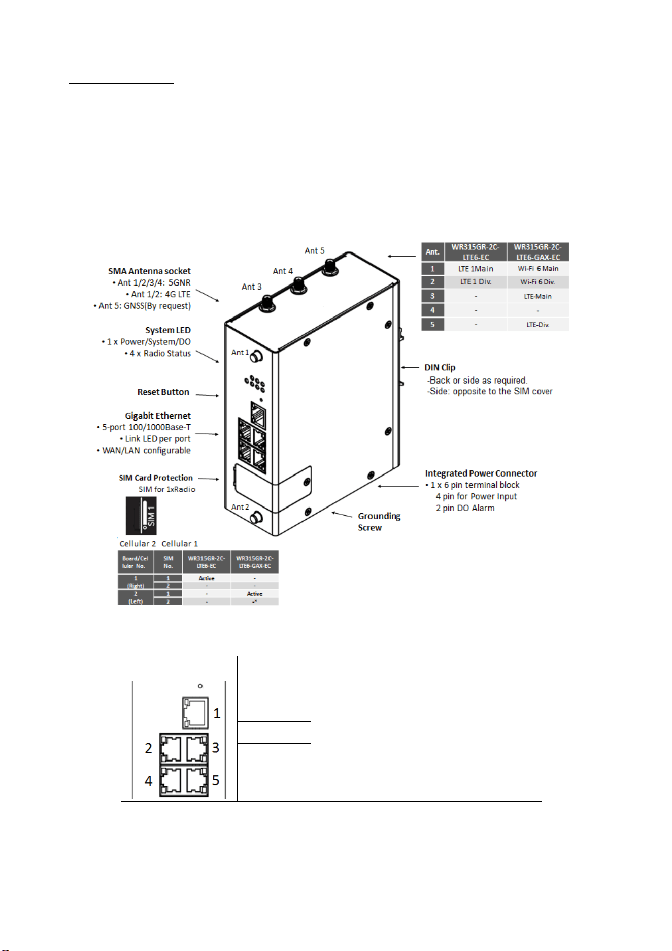
The front panel from WR315GR routers include 5 ports Giga Ethernet (100/1000 Base-T, RJ45), System + Ethernet +
Radio LEDs, Reset button, 1 x 6-pin terminal block connector (4 pin for power inputs and 2 pin for Relay Output) and
1 chassis grounding screw on bottom side. There are 5 SMA antenna sockets, 5GNR connection usually requires 4
antennas, 4G LTE connection usually requires 2 antennas and one is reserved for GPS/GNSS. On the rear side of the
device, there is DIN rail clip attached.
WR315GR-2C-LTE6-GAX-EC
Ethernet Port Map:
Port Map
Port Number
Bridge Mode
Router Mode(1xWAN)
Port 1
LAN
WAN 1 (Default)
Port 2
LAN
Port 3
Port 4
Port 5
Default port configuration is Router Mode in WR315GR-2C-LTE6-GAX-EC, the default IP of the interface LAN ports:
192.168.10.1. Default IP of the interface WAN is DHCP Client

17
Antenna Map:
WR315GR-2C-LTE/LTE6-EC
WR315GR-2C-LTE6-GAX-EC
Ant 1
LTE/LTE6 Main
Wi-Fi Main
Ant 2
LTE/LTE6 Div.
Wi-Fi Div.
Ant 3
-
LTE6 Main
Ant 4
-
-
Ant 5
-
LTE6 Div.
Note: *GNSS software by request
Note: Due to the different number of antennas used by 5GNR/4G LTE/3G/2G model, the feature of the antenna
number may be different, the unused antenna positions will be covered by caps (even it has no functionality).
Note: If you only connect one antenna, please always connect the Main Ant. With one antenna attached, the
connection speed, signal quality, and performance will be affected and cannot be guaranteed.
2.2 INSTALLATION
After unpack the box, follow the steps below in order to properly connect the device. For better signal/performance,
put the device in a clearly visible spot, as obstacles such as walls and doors hinder the signal.
1. First, assemble router by attaching the necessary antennas and inserting the SIM card.
2. To power up router, please use the qualified power supply, connect the power input and reserved 24V@3A for the
router.
2.3 WIRING THE POWER INPUTS
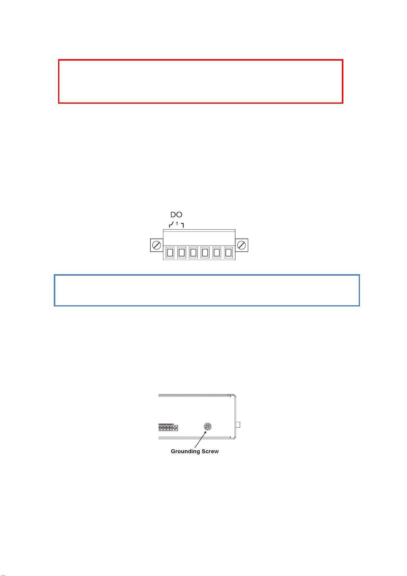
Power Input port in the router provides 2 sets of power input connections (P1 and P2) on the terminal block. On the
picture below is the power connector.
Wiring the Power Input
1. Insert the positive and negative wires into the V+ and V- contact on the terminal block connector.
2. Tighten the wire-clamp screws to prevent the power wires from being loosened.
3. Connect the power wires to suitable DC Switching type power supply. The typical input DC voltage is 24V,
18
range of 9VDC to 48VDC.
2.4 WIRING THE ALARM RELAY OUTPUT (DO)
The relay output contacts are located on the front panel of the router. The relay output consists of the 2-pin
terminal block connector that used to detect user-configured events. The two wires attached to the fault contacts
form a close circuit when a user-configured event is triggered. If a user-configured event does not occur, the fault
circuit remains open. The fault conditions such as Ethernet port link down or other pre-defined events (by
customized) which can be configured in the device. Screw the DO wire tightly after digital output wire is connected.
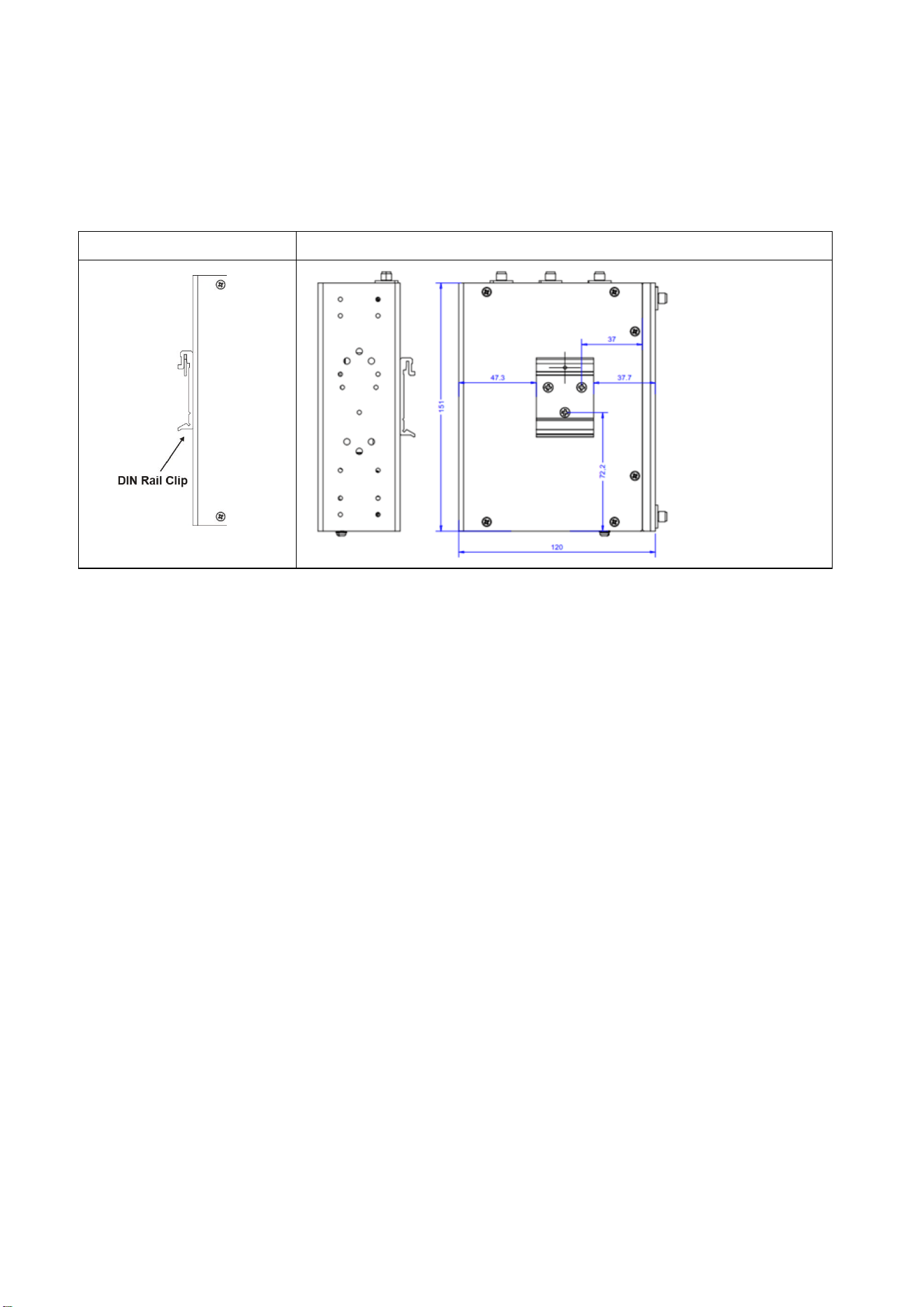
2.5 CONNECTING THE GROUNDING SCREW
Grounding screw is located on the bottom side of the router. Grounding Screw helps limit the effects of noise due to
electromagnetic interference (EMI) such as lighting or surge protection. Run the ground connection from the ground
screw to the grounding surface prior to connecting devices. And tighten and wire to chassis grounding for better
durability.
NOTE: The relay contact only supports 1 A current, DC 24V. Do not apply voltage and current higher than
the specifications.
WARNING: Turn off DC power input source before connecting the Power to the terminal block
connectors, for safety purpose. Don not turn-on the source of DC power before all of the
connections were well established.
19
2.6 DIN RAIL MOUNTING
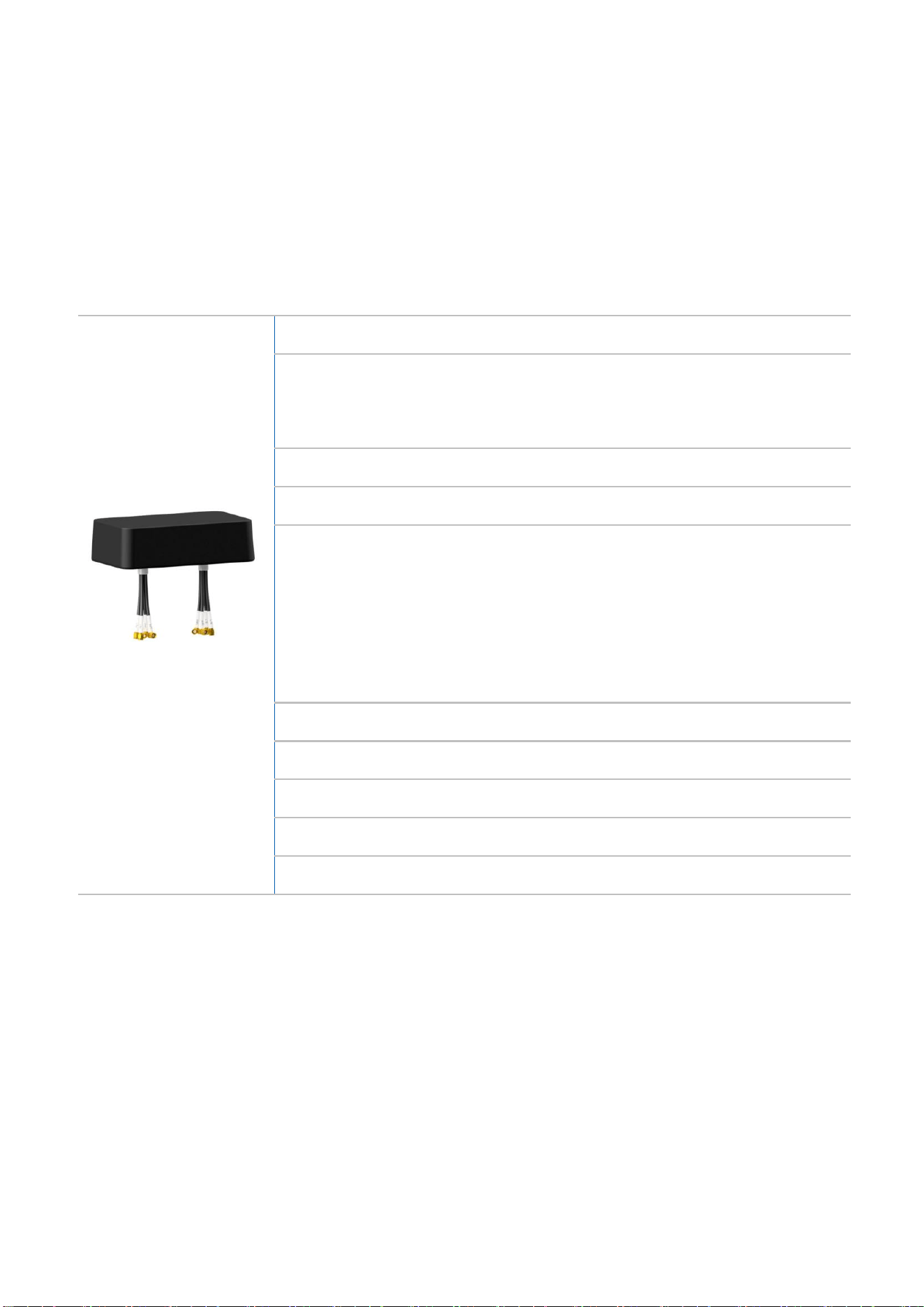
The EN50022 DIN-Rail plate should be already attached to the Side/back panel of the device screwed tightly. If user
needs to reattach the DIN-Rail attachment plate to the device, make sure the plate is situated towards the top, as
shown by the following figures.
Back (By Manually Change)
Rear/Side mounting: opposite to the SIM cover (WR315GR-2C-LTE6-GAX-EC)
To mount the router on DIN Rail track, do the following instruction:
1. Insert the top side of DIN Rail track into the slot of DIN Rail clip.
2. Lightly clip the bottom of DIN-Rail to the track and make sure it attached well.
3. To remove the device from the track, reverse the steps.
Note: In WR315GR-2C-LTE6-GAX-EC, the DIN Clip is pre-installed at the factory for Side mounting. The DIN clip is
located opposite to the SIM card cover. If you need to change to rear mounting, move the DIN to the rear screw hole.
20
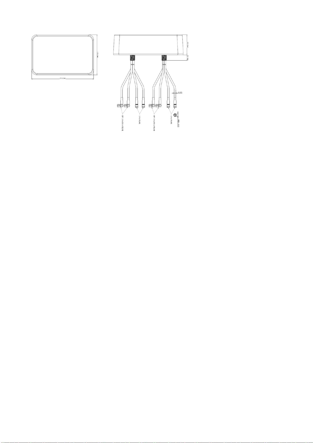
2.7 Optional ANTENNA
WR315GR-2C-LTE6-GAX-EC supports 4 antenna sockets, where 2G/3G/4G LTE and Wi-Fi antennas are supported.
In the charging station project, the RFA-J21-T565-13701 antenna connectors will be connected together with the
router, and the antenna will be roof-mounted on the top of the chassis box. Note: This antenna was custom-made
for this project and is for professional installation only. For information on the context of choosing this antenna, or
if you have similar application needs, please contact our sales team for details.
RFA-J21-T565-13701 Major Spec.:
Multi-band Roof Mount
2x (LTE + Wi-Fi) Antenna
RFA-J21-T565-13701
(WR315G-2C-LTE6+GAX-EC)
Frequency of Wi-Fi:
2400~2500/5150~7120MHz
Peak Gain & Ave. Efficiency of Wi-Fi:
(Frequency: Connector Number:; Peak Gain(Efficiency))
2400
∼
2500MHz:
P1:4.4dbi(47%); P4:4.0dbi(49%); P2:3.9dbi(44%); P3:3.8dbi(44%)
5150-7125MHz:
P1:4.9dBi(27%); P4:5.0dBi(29%); P2:4.2dBi(24%); P3:4.6dBi(28%)
Connector of Wi-Fi:
2x2 RP SMA PLUG (Professional Engineer for Installation Required)
Frequency of LTE:
617-960MHz / 1710~2700MHz
Peak Gain & Ave. Efficiency of LTE:
(Frequency: Connector Number:; Peak Gain(Efficiency))
617-960MHz:
P1:2.8dBi(34%); P4:4.1dBi(42%); P2:4.1dBi(44%); P3:3.6dBi(44%)
1710-1755MHz:
P1:4.3dBi(52%); P4:4.8dBi(47%); P2:4.1dBi(41%); P3:3.2dBi(48%)
1785-2170MHz:
P1:6.9dBi(51%); P4:5.1dBi(49%); P2:6.4dBi(51%); P3:6.5dBi(51%)
2300-2400MHz:
P1:3.2dBi(42%); P4:2.5dBi(40%); P2:3.9dBi(39%); P3:2.7dBi(45%)
2400-2500MHz:
P1:4.7dBi(37%); P4:3.4dBi(38%); P2:2.4dBi(38%); P3:2.8dBi(38%)
Connector of LTE:
2x2 SMA PLUG
Dimension:
210(L) x 135(W) x 60(H)mm; 76.9(H)mm include through-hole mounting ring
Mounting:
Roof-mount/Through-hole mount
Cable Length:
2x4 RG58 / Length=2M
Environment:
Temperature: -40~70
℃, Humidity: 95%@25℃
Dimension:
21

22
WR315GR-2C-M2 series are supported with up to 5 antenna sockets, where 2G/3G/4G LTE/5GNR and GPS/GNSS
antennas are supported. All of the antennas are connected to the router by screwing the SMA connector on the front
panel of the router. WR315GR-5GM2-2C does not come with default antennas while shipment, please order them
separately. You can also order the Router with below Antennas in the package, please contact our sales if necessary.
Optional 5GNR Antenna by request
Optional 4G LTE Antenna by request
Frequency
690 ~ 960 MHz / 1710 ~ 2700 MHz
V.S.W.R
<= 3.0
Radiation
Omni
Peak Gain
3.15dBi
690MHz: 1.36dBi, 960MHz: 1.37dBi,
1710MHz: 3.12dBi, 1800MHz: 1.29dBi
1900MHz: 2.63dBi, 2100MHz: 1.47dBi,
2170MHz: 1.14dBi, 2500MHz: 3.15dBi
2600MHz: 2.46dBi, 2700MHz: 1.89dBi
Directional
Omni-directional
Impedance
50 Ohm
Connector
SMA Male
Dimension
200xΦ13 mm
Operational Temperature
- 20 °C ~ +65 °C
Frequency
690 ~ 960 MHz / 1710 ~ 2700 MHz/
3200~3800MHz/ 4400~5900MHz
V.S.W.R
<= 2.5
Peak Gain
(major)
Up to 5.7dBi
690MHz: 0.73dBi, 960MHz: 2.98dBi,
1710MHz: 3.11dBi, 1800MHz: 2.54dBi,
1900MHz: 2.42dBi, 3300MHz: 5.6dBi,
3500MHz: 4.12dBi, 3800MHz: 4.92dBi,
4000MHz: 3.75dBi, 5000MHz: 4.18dBi
Directional
Omni-directional
Impedance
50 Ohm
Connector Type
SMA Male
Dimension
222xΦ13 mm, 27mm width
Operational Temperature
- 10 °C ~ +70 °C
23
2.8 SIM CARD INSTALLATION
SIM Card Slot
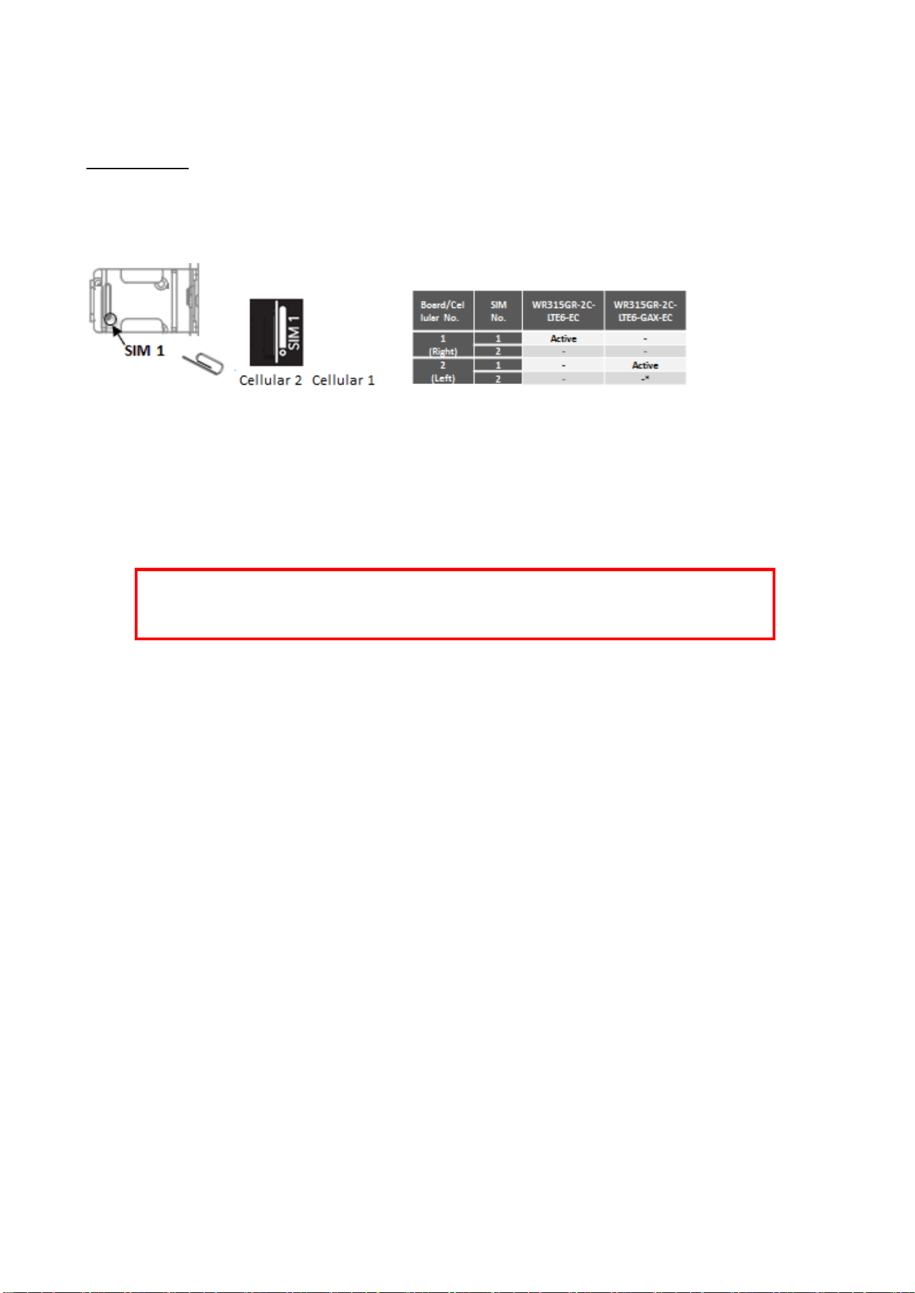
The SIM Card Slot is used to insert the cellular card. The WR315GR-2C-LTE6-GAX-EC supports one SIM. It is SIM 1
location of the CELL 2 PCBA board.
(Note: EC OS version software supports one SIM only due to the restriction of current OpenWRT OS.)
To install/uninstall SIM card:
1. Use screwdriver to loosen screws and remove SIM cover.
2. Insert a paper clip or a SIM-eject tool into the hole beside the SIM socket. Push in towards the device, but
don’t force it. The SIM 1 is the primary SIM in the default configuration.
3. (When install) Draw out SIM tray and install SIM card on top side of tray
(When uninstall) Draw out SIM tray and uninstall SIM card
4. Insert tray back to SIM socket and reattach SIM cover.
WARNING: Be careful when install the SIM Card, wrong installation procedure will cause damage.
Please follow the mechanical print out to install the SIM Card.
SIM indication on front panel
24
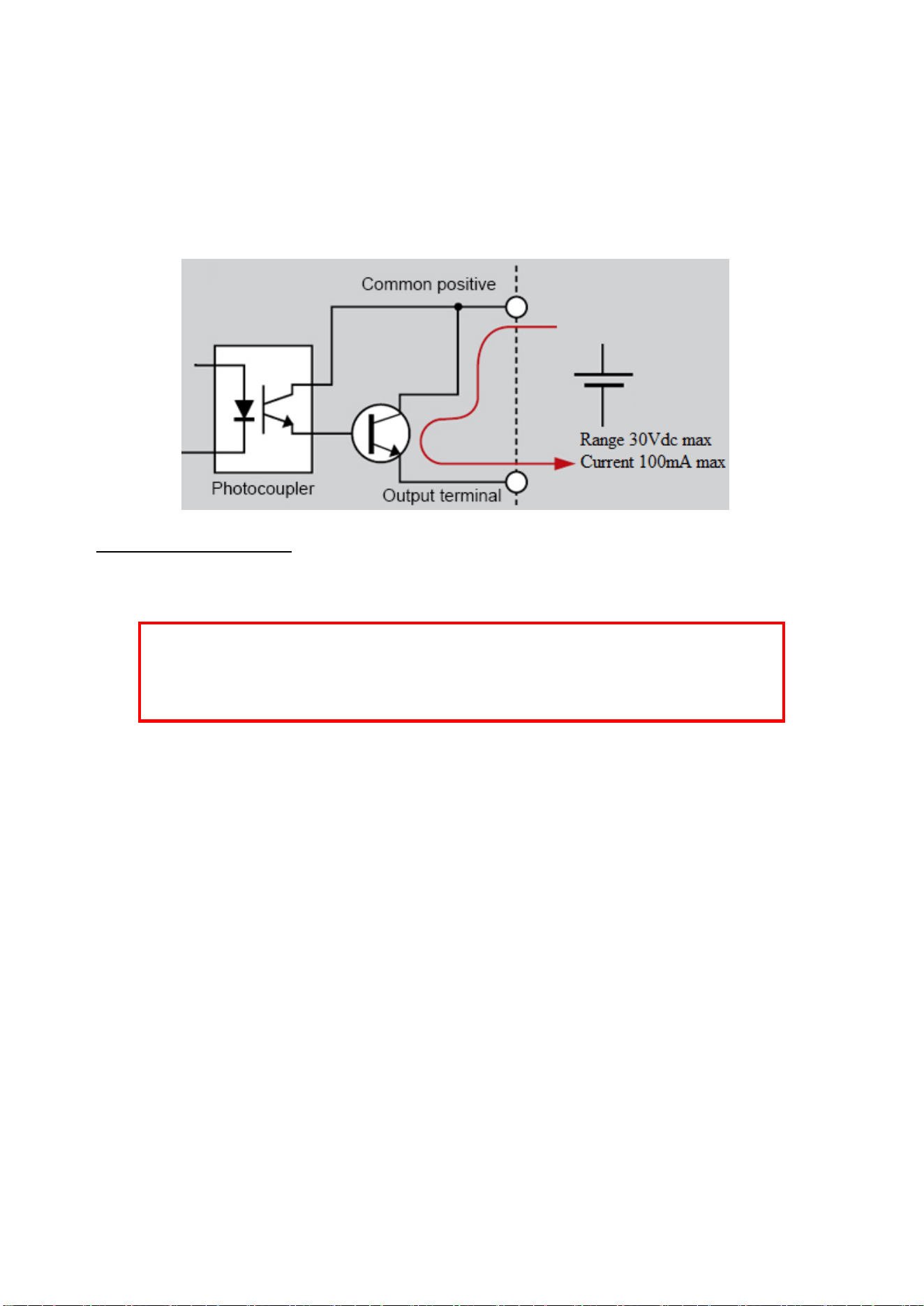
2.9 WIRING THE DIGTIAL OUTPUT (Reserved)
The digital output of the terminal block is used to detect user-configured events. The two wires attached to the fault
contacts form a close circuit when a user-configured event is triggered. If a user-configured event does not occur,
the fault circuit remains opened.
Wiring the Digital Output
1. Insert the positive and negative wires into the DO+ and DO- contact on the terminal block connector.
2. Tighten the wire-clamp screws to prevent the wires from being loosened.
Note: WR315-M2 supports Relay Output. Not every model of WR315 series supports Digital Input and Digital Output.
The feature is reserved for the WR315GR-M2 with Digital Output model only.
WARNING: Please confirm the wire installation according to the above steps, otherwise it would
not work properly. It only supports 0.1 A current, DC 30V. Do not apply voltage and current higher
than the specifications.

25
2.9 HARDWARE WATCHDOG
The device provides a hardware watchdog mechanism for critical event, such as system reboot is to cut the power of
the whole device to get a clean restart of all components.
The device also provides a “dying gasp” alert. The router can generate syslog event or SNMP trap to target server
when the router loses power. (Note: The dying gasp alarm software feature is not supported in current EC OS.)
Some of the features are also available as watchdog. Refer to:
Ping Watchdog
Periodic Reboot/Restart Inteface

26
2.10 LED INDICATION
WR315GE-2C-LTE6-GAX-EC (Model with LTE Cat.6 + Wi-Fi 6 client modules)
LED
Status
Description
WR315GR-2C-LTE6
-GAX-EC
Ra
Green On
11ax 5GHz Client mode
Green Blinking
11ax 5GHz Transmitting
Off
Disabled
Rb
Green On
11ax 2.4G Client mode
Green Blinking
11ax 2.4G Transmitting
Off
Disabled
Rc
OFF
N/A
Rd
(Reserved)
(Controlled by module)
Re
Green On
SIM detected
Off
SIM not insert
Rf
Green On
4G/3G/2G Signal Strength
Good (-90≦rsrp)
Green Blinking
4G/3G/2G Signal Strength
Medium(-100≦rsrp≦-90)
Off
4G/3G/2G Signal Strength
Low(rsrp≦-100)
Rg
(Reserved)
(Controlled by LTE module)
Rc LED is not used in this model.
Rd/Rg LED is applied to Radio module’s LED, its behavior is depends on radio module.

27
3. WR315G-2C-LTE6-GAX-EC EC OS Introduction
3.1 EC OS Software Specification:
Software (EC OS Version, OpenWRT, WR315GR-2C-LTE6-GAX-EC series)
Applied Model
WR315GR-2C-LTE6-G-EC, WR315GR-2C-LTE6-GAX-EC, WR315GR-2C-M2-EC,
WR315GR-2C-LTE-G-EC, WR315GR-2C-LTE-GAX-EC
OS
OpenWRT 23.05
Web Server
luCI Web Interface
Terminal Server
(SSH)
Secure encrypted communications between two untrusted hosts over an insecure
network
Kernel
GNU/Linux kernel v5.15
Internet Protocol
Suite
TCP, UDP, IPv4, IPv6, ICMP, ARP, HTTP, DHCP, NTP, SSH, PPP, SFTP, SSL,
SCP
Internet Security
Suite
OpenVPN, IPSec, Netfilter/iptables
Network Control
Protocol
Router mode (1xWAN+4xLAN), NAT/PAT, VLAN, QoS, NTP client/server, IGMP,
PPP, PPPoE, SSL, port forwarding
Network Security
HTTPS, SSH, VPN tunnels, SFTP, DMZ, firewall
(IP filtering, MAC address filtering, inbound/outbound port filtering)
Cryptographic
AES, SHA, OpenSSL, random generator
Cellular Networking
Features: Cellular Configuration Radio on/off, 2G/3G and 4G modes configurable,
Enter PIN code for SIM Security, Connection status, display module info, GPS
positioning(by model*)
Modem manager: uQMI(user QMI) for talking to WWAN modems and devices that
speak the Qualcomm MSM Interface (QMI) protocol.
*EC version doesn’t support dual SIM due to uQMI restriction.
Time Management
NTP, Cellular Time(by module)
Watchdog
Periodic Reboot, Ping watchdog for keep-Alive connection monitoring, Restart
interface for mobile modem, run script
Web GUI
Management
Based on LuCI WebGUI
System Setting, NTP Setting, Router Password setting with strength check, SSH
Access and Key upload, HTTPS, init script startup setting, configuration
backup/restore, firmware upgrade, system reboot, watchcat(watchdog), ser2net,
Interface configuration, Wi-Fi interface setting, DHCP server/client, DHCP Relay,
DNS, firewall setting, static router, Diagnostic Ping, traceroute, Nslookup, Device
Status and Mobile Information
WLAN Configuration
(Model with WLAN
module)
Support Wi-Fi Client mode.
WLAN Basic Settings: Radio on/off, mode selection, 2.4G/5G 11ax Band and
Frequency selection, SSID configuration, Wireless Security encryption includes
WPA3-SAE and WPA2-PSK/WPA-PSK/Open, advanced WLAN settings, WLAN
MAC Filter, 802.11r fast transition

28
3.2 WR315G-2C-LTE6-GAX-EC QIG
This chapter introduces the Quick Installation Guide of the WR315G-2C-LTE6-GAX-EC.
Overview
The WR315GR-2C-LTE6-GAX-EC is a high-performance industrial router featuring 4G LTE and Wi-Fi 6 connectivity.
Powered by a dual-core 880 MHz CPU, it includes two expansion sockets—one for an LTE Cat.6 cellular module and
one for a Wi-Fi 6 client module. The router provides five Gigabit Ethernet ports, including one WAN port and four
LAN ports, supporting routing between Ethernet LAN and WAN networks. Either the 4G cellular module or the Wi-Fi
6 client module can function as a Wireless WAN interface, enabling wireless Internet connectivity. The router runs
on the OpenWrt-based embedded operating system, referred to as EC OS, which offers both the UCLI web interface
and SSH access for management, along with a rich set of software features.
Model
Description
WR315GR-2C-LTE6-G-EC
Industrial Secure Router, Dual Core, 5GbE, 1 Relay, EC OS, LTE6-G
WR315GR-2C-LTE6-GAX-EC
Industrial Secure Router, Dual Core, 5GbE, 1 Relay, EC OS, 802.11ax WLAN6 client,
LTE6-G
Power Input: 24VDC (9V~48VDC)
LTE6-G: (FCC ID: 2AJYU-8XM0004)
LTE-FDD: B1/B2/B3/B4/B5/B7/B8/B12/B13/B14/B17/B18/B19/B20/B25/B26/B28/B29/B30/B32/B66
LTE-TDD: B38/B40/B41/B42/B43/B46/B48
WLAN 6: 2.4GHz/5GHz 802.11ax/ac/n/g/a/b, MU-MIMO 2T2R (FCC ID RAS-MY7922A22M)
Installation
・SIM Card Slot
To install/uninstall SIM card:
1. Use screwdriver to loosen screws and remove SIM cover.
2. Insert a paper clip or a SIM-eject tool into the hole beside the SIM socket.
Gently push inward, do not use excessive force. SIM 1 is the primary SIM
in the default configuration.
3. To Install: Draw out SIM tray and place the SIM card on top side of tray
To uninstall: Draw out SIM tray and remove SIM card
4. WR315G-2C-LTE6-GAX-EC supports only one SIM card due to limitation of OpenWrt system.
Warning: Be careful when install the SIM Card, wrong installation procedure will cause damage. Make
sure the SIM Card is facing the correct position.
29
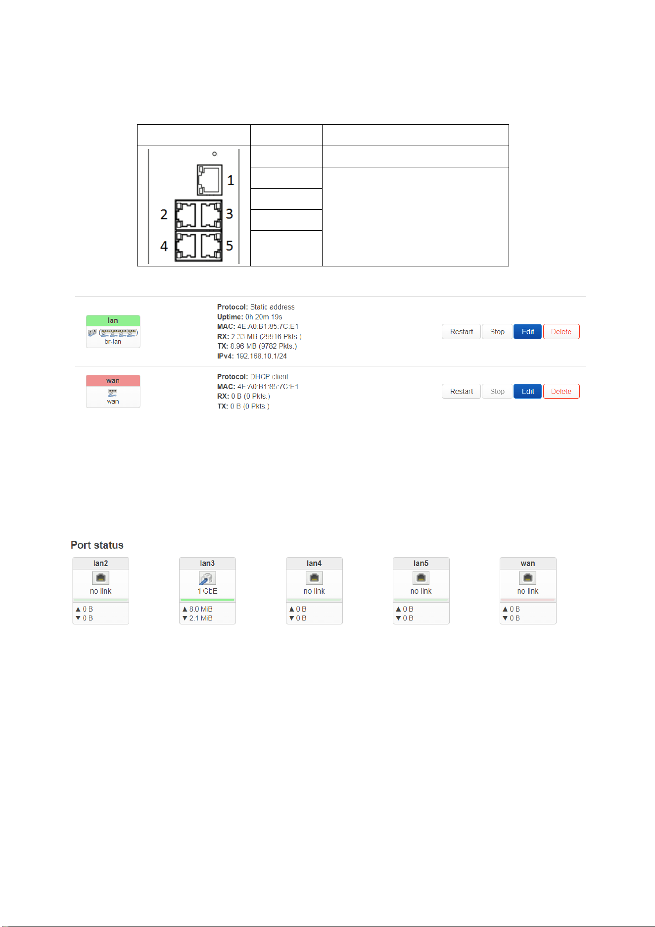
・Interface - Ethernet
WR315G-2C-LTE6-GAX Ethernet Port Map:
Default Ethernet port configuration in WR315G-2C-LTE6-GAX is Router Mode, LAN to WAN routing enabled.
Port Map
Port Number
Router Mode(Default)
Port 1
WAN (Default: DHCP Client)
Port 2
LAN
(Default IP: 192.168.10.1)
(Web GUI: Lan 2/3/4/5)
Port 3
Port 4
Port 5
Interface Name:
The default IP of the interface LAN ports: 192.168.10.1
The default IP of the interface WAN port: DHCP Client
Note: “wan6” is the IPv6 configuration of WAN interface. It is usually not used.
Port Status in Web GUI- Status:
30
・Interface - Cellular
The router support 4G LTE Cat.6 cellular interface.
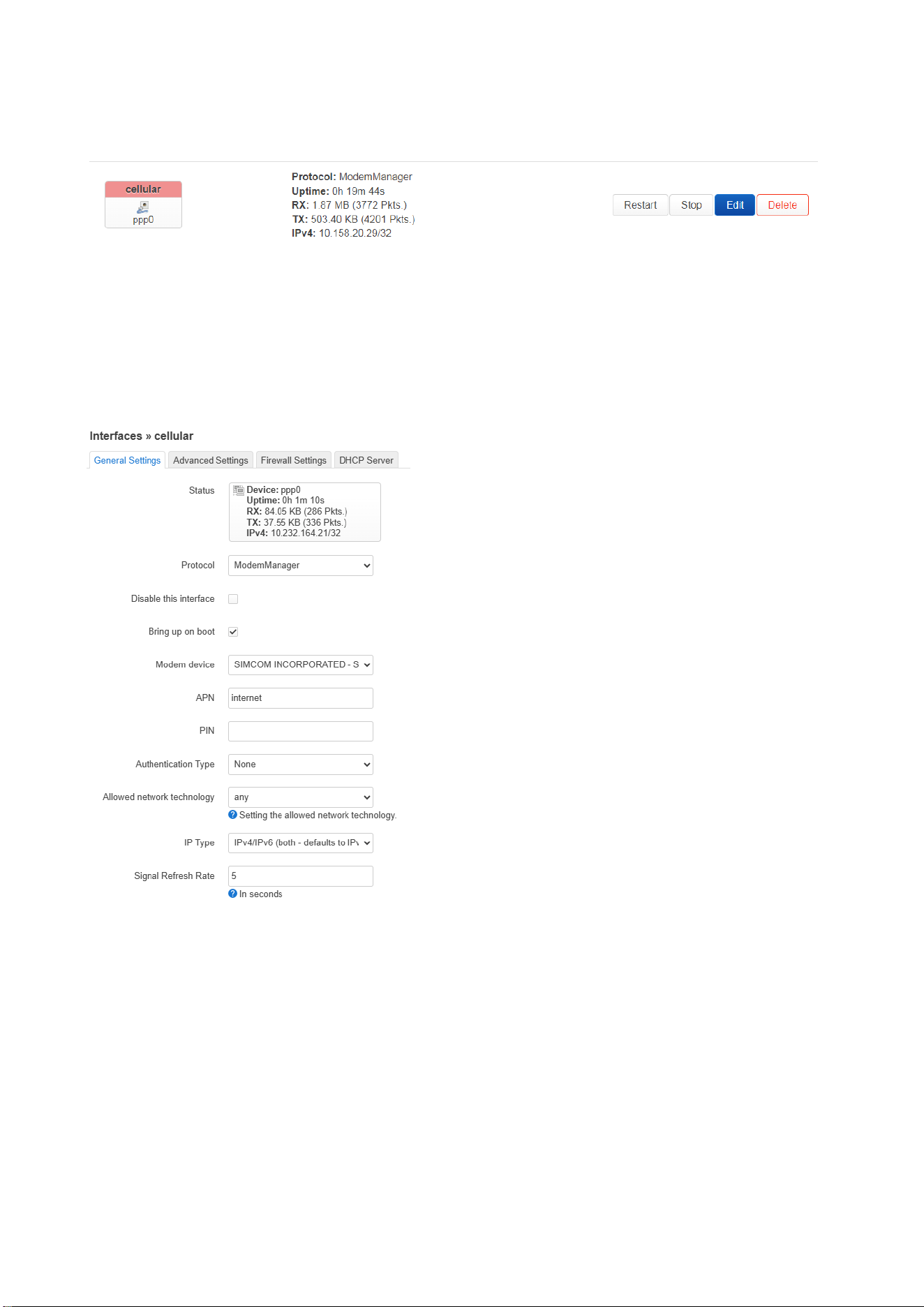
Cellular Interface: Default is Enabled.
Logical name: cellular (ppp), works as WAN interface.
Apn: internet
Auth: none
Iptype: ipv4v6
Signal Refresh Rate: 5 second
31
・Interface – Wi-Fi
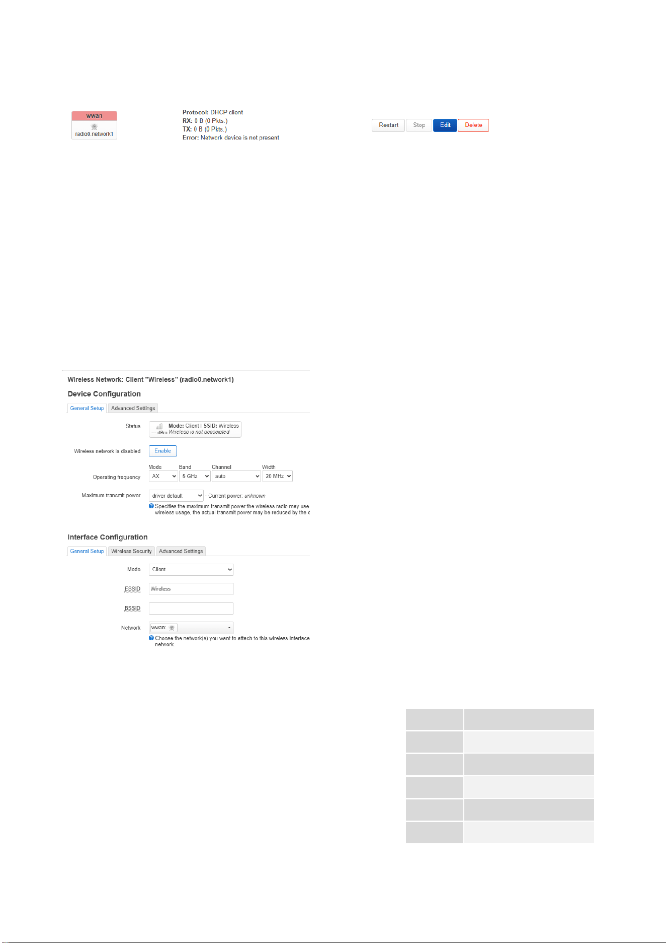
The router supports Wi-Fi 6 (client) interface.
Wireless LAN:
Default is Disabled.
Default value after enabled:
Wireless Mode: Client Mode
Radio Setting: IEEE802.11ax, 5G, Auto channel, Bandwidth 20Mhz
SSID: Wireless
Encryption: None
Network Interface: wwan
Default IP: DHCP Client
Web GUI:
・Antenna
WR315G-2C series supports max. 5 SMA socket, which are for 4G
LTE/5GNR, GPS/GNSS or Wi-Fi antennas. User must install the antennas
to correct socket while use. WR315G-2C-LTE6-GAX-EC uses the Antenna
1/2/3/5 sockets as shown in the table on the left.
Note: Due to the different number of antennas used by LTE/WLAN
models, the unused antenna positions will be covered by caps.
WR315GR-2C-LTE6-GAX-EC
Ant 1
Wi-Fi Main
Ant 2
Wi-Fi Div.
Ant 3
LTE6 Main
Ant 4
-
Ant 5
LTE6 Div.

32
・Wiring the Power Input
1) Insert positive and negative wires into V+ and V- contact on the terminal block connector.
2) Tighten the wire-clamp screws to prevent the power wires from being loosened.
3) Connect the power wires to suitable DC Switching type power supply. The typical input DC
voltage is 24V.
・Wiring the Relay Output/DO Alarm
The relay output of the 6-pin terminal block connector is used to detect user-configured events,
for example the Ethernet port link down. The two wires attached to the fault contacts form a
close circuit when a user-configured event is triggered. If a user-configured event does not occur,
the fault circuit remains opened.
・Grounding Screw
The grounding screw is located on the bottom side of the router. For avoiding system damage by
noise or electric shock, establish a direct connection between the ground screw and the
grounding surface prior to connecting devices.
・DIN Rail mount
To mount the router on the DIN Rail track, insert the upper end of the DIN‐Rail clip into the back of the
DIN‐Rail track from its upper side and lightly push the bottom of the DIN‐Rail clip into the track. The
DIN Rail should comply with DIN EN50022 standard. Using wrong DIN rail may cause unsafe
installation.

33
・LED:
WR315GE-2C-LTE6-GAX-EC (Model with LTE Cat.6 + Wi-Fi 6 client modules)
LED
Status
Description
WR315GR-2C-LTE6
-GAX-EC
Ra
Green On
11ax 5GHz Client mode
Green Blinking
11ax 5GHz Transmitting
Off
Disabled
Rb
Green On
11ax 2.4G Client mode
Green Blinking
11ax 2.4G Transmitting
Off
Disabled
Rc
OFF
N/A
Rd
(Reserved)
(Controlled by module)
Re
Green On
SIM detected
Off
SIM not insert
Rf
Green On
4G/3G/2G Signal Strength
Good (-90≦rsrp)
Green Blinking
4G/3G/2G Signal Strength
Medium(-100≦rsrp≦-90)
Off
4G/3G/2G Signal Strength
Low(rsrp≦-100)
Rg
(Reserved)
(Controlled by LTE module)
Rc LED is not used in this model.
Rd/Rg LED is applied to Radio module’s LED, its behavior is depends on radio module.
34
3.3 PREPARATION for Management
To access the management interface of the EC OS based on the OpenWrt operating system, WoMaster routers
provide two primary access methods over the network: web-based management and SSH/Telnet command-line
management.
Web management is the most commonly used and user-friendly method. It allows users to monitor device status
and perform basic configuration tasks through a standard web browser via the built-in LuCI web interface. This
interface provides access to system information, network settings, and essential router controls.
If the web interface is unavailable due to network issues or misconfiguration, users can alternatively access the
router via SSH or Telnet. This method provides full access to the router's command-line interface (CLI), allowing
advanced configuration and troubleshooting.
PREPARATION FOR WEB MANAGEMENT
WoMaster router running OpenWrt-based EC OS provides a LuCI Web-based management interface accessible
through standard web-browser such as Microsoft Internet Explorer, or Mozilla, or Google Chrome, to access and
configure the router management on the network.
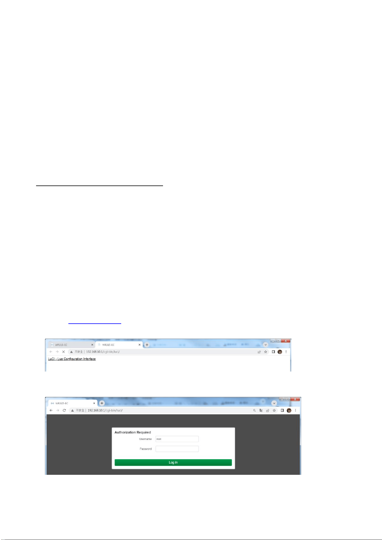
1. Plug the DC power to the router and connect router to computer via Ethernet.
2. The router’s default IP address is 192.168.10.1.
3. Check that PC has an IP address on the same subnet as the router. For example, assign your PC and IP address
like 192.168.10.2, with a subnet mask of 255.255.255.0 and a default gateway of 192.168.10.1
4. Alternatively, if the router’s DHCP Server is enabled, set your PC to DHCP Client mode to obtain an IP address
automatically.
5. Open a command prompt and ping 192.168.10.1 to verify that the router is reachable.
6. Launch the web browser (Internet Explorer or Mozilla Firefox or Google Chrome) on the PC.
7. Type http://192.168.10.1 (or the IP address of the router) in the address bard. Press Enter and the login page
will appear.
8. Type user name and the password.
The default user name: root and password: root. Then click Login.
35
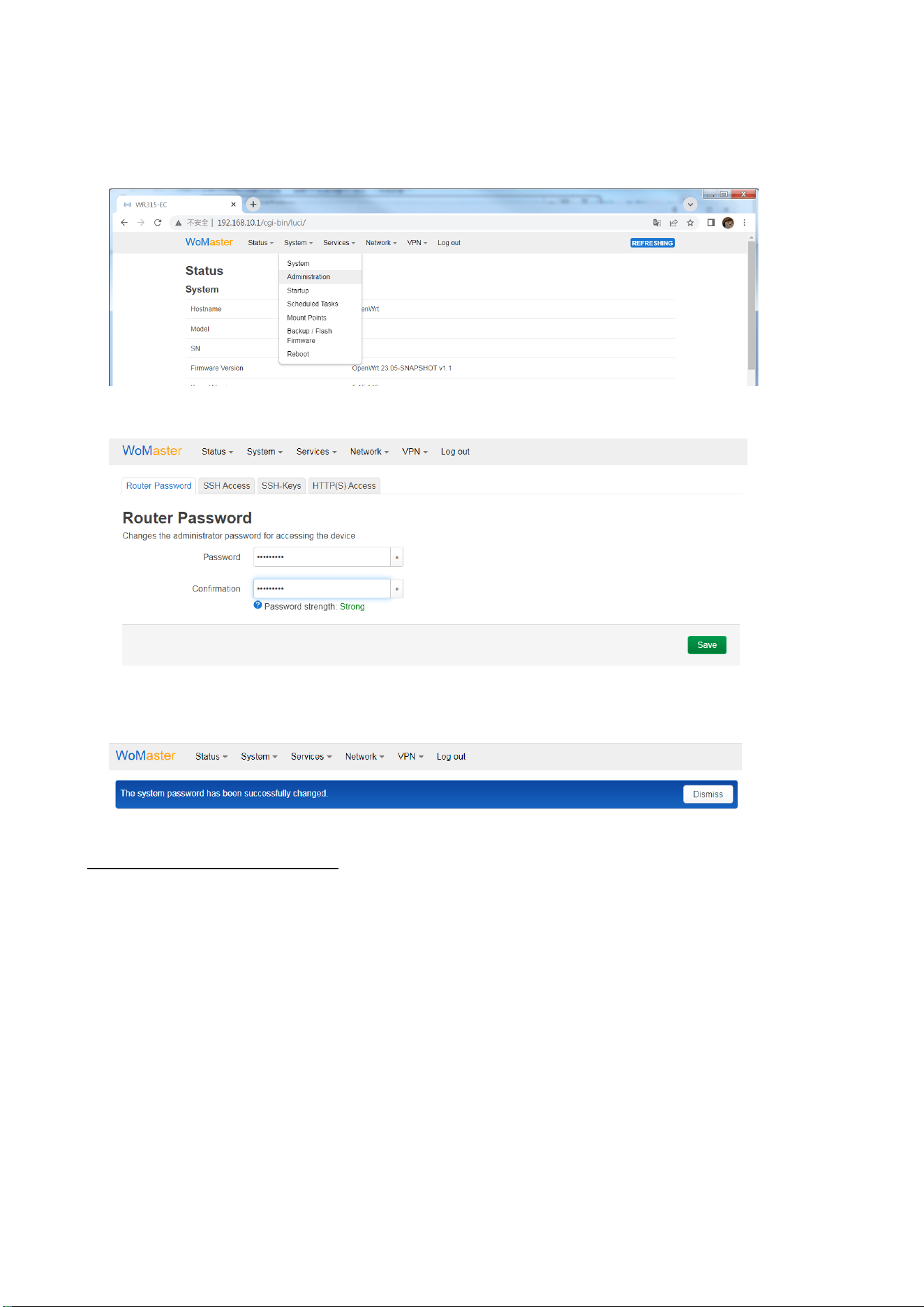
9. For security concern, it is commend to change the default password with a new password in first Login. Go
to “System” –> “Administrator” page, you can enter new password and Save to apply the change. Please
follow the prompt to enter new password.
Then enter with the new password and click “Save” to apply the change.
After clicking “Save”, a prompt message will appear saying “The system password has been successfully
changed.” Click “Log out”, you will be required to use the new password in the next time you login.
Using SSH to Configure OpenWrt
OpenWrt supports remote command-line access via SSH, allowing users to perform advanced configurations and
troubleshooting.
1. Ensure network connectivity between your PC and the OpenWrt router (e.g., same subnet or reachable IP).
2. On your PC, open a terminal or SSH client (such as PuTTY, download OpenSSH for Windows or a Linux
terminal).
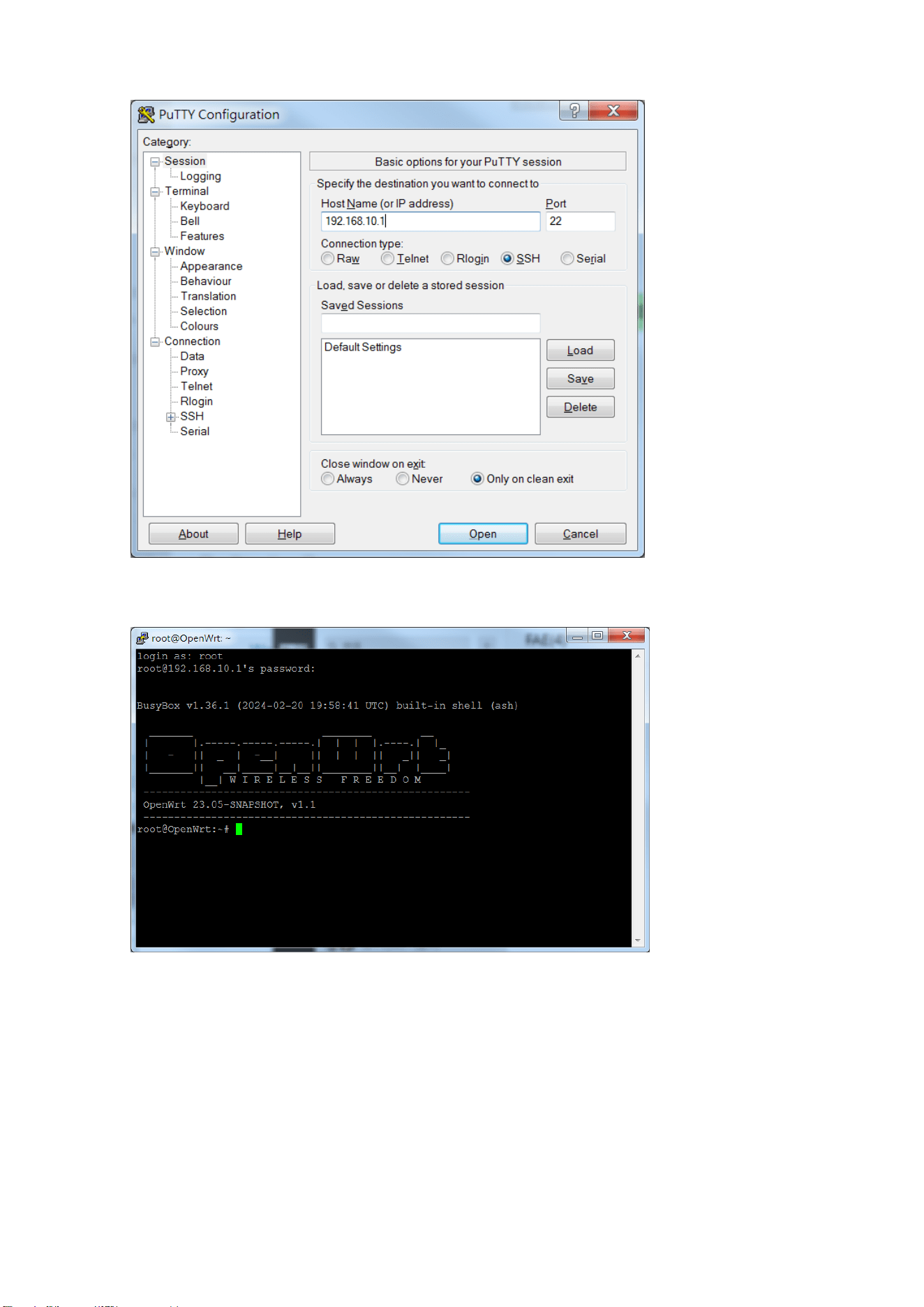
3. Using Putty:
Type the IP address of the router and use the access Port 22.
36
The SSH console will appear:
The default user name: root and password: root.
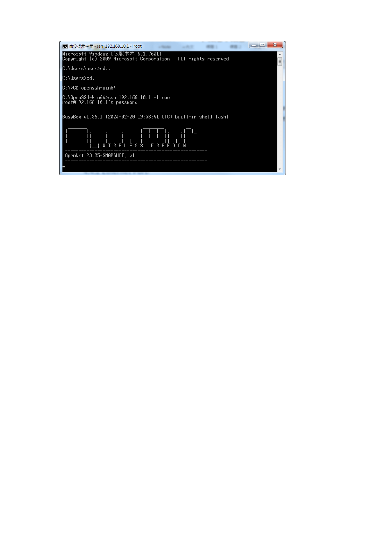
4. In Window OS 10 1809+, the SSH(OpenSSH) console is built-in. For earlier OS version, please download the
OpenSSH through internet for your windows.
Through the Window Command prompt, you can enter the following command to connect.
ssh 192.168.10.1 -l root
(Replace 192.168.10.1 with your router's actual IP address.) [ -l login_name]
When prompted, enter the root password. (default password: root)
37
38
3.4 LuCI Web Management
The following content mainly introduces the major Web GUI settings. Since openwrt is a public system, if it is not
listed here, you can also find its web gui settings through the Internet or the openwrt website.
3.4.1 STATUS
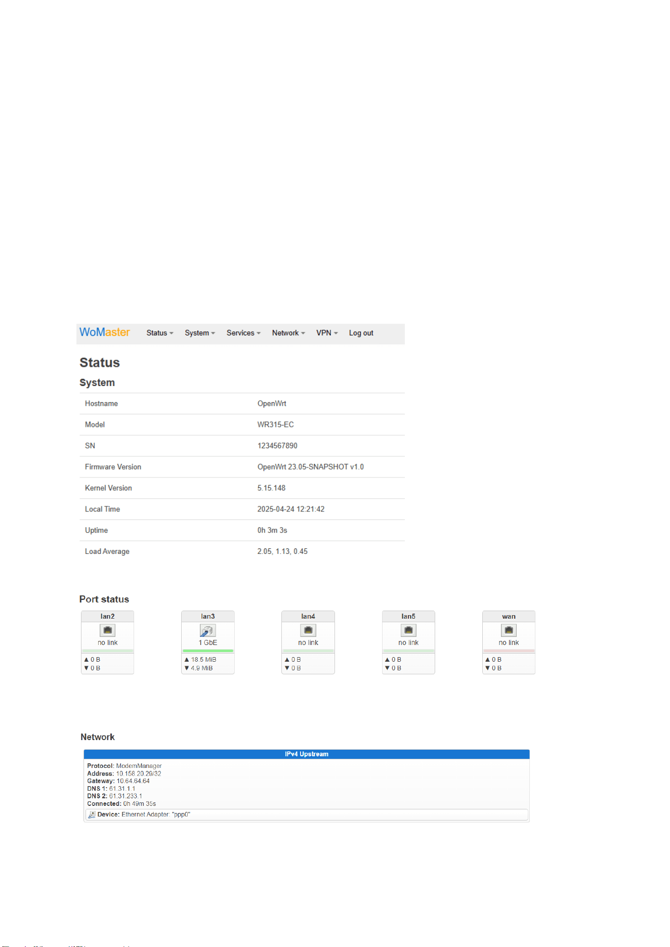
In the OpenWrt LuCI web interface, the Status section provides a comprehensive overview of the system's current
state and runtime information. It is commonly used for diagnostics, monitoring, and quick verification of network
and system status.
Key Features Available Under the Status Menu:
Overview
General system information: Hostname, Model, SN, Firmware version, Kernel Version, Local Time, Uptime, Load
average, memory usage, Storage space…etc.
Port Status: It indicates the link status of the LAN port 2/3/4/5 and WAN port (port 1).
Network: It provides the information of the upstream interface, includes the IP addresses, connected time, active
interface, DHCP status.
39
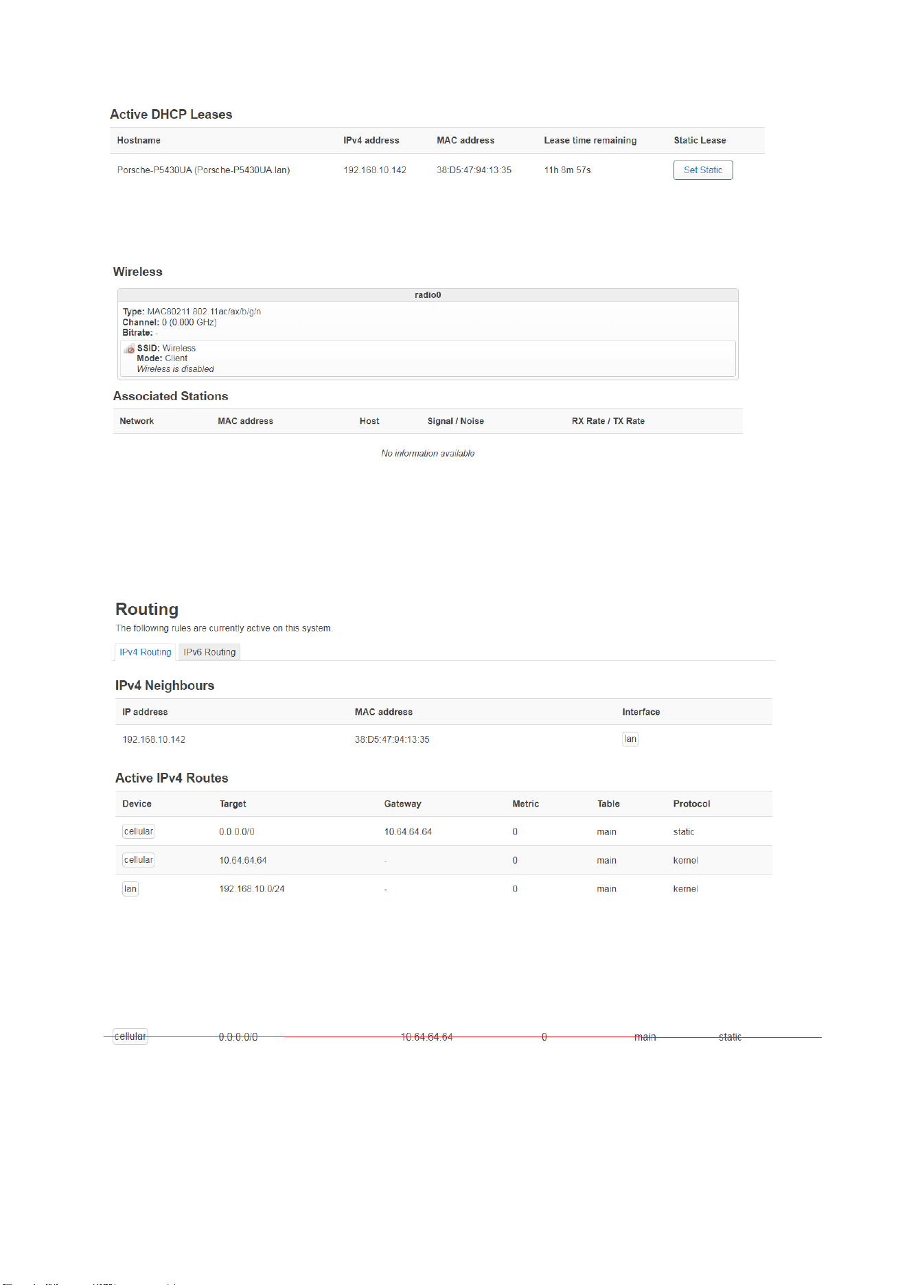
Wireless: It shows the Wi-Fi Client status (default is disabled) and associated Stations. It shows the real-time view
of wireless interfaces and modes and associated stations.
Routes
Lists active IPv4 and IPv6 routing tables.
Active IPv4 Routes can check the IP address of the activated interfaces.
Note: The entry of “Target 0.0.0.0/0” is very important!
Once you have more than one default gateway, for example both the 4G cellular and Wifi client enabled to
internet, the device's routing table will be constantly changing, and if it's missing entries, that means you can
access the router, but can’t access the Internet.
For example: If you are missing the cellular interface’s 0.0.0.0/0 entry, it means the 4G network is not available,
you will need to restart the cellular interface and remove the unused wan/wwan (wireless client) interfaces in
case it happen again.
40
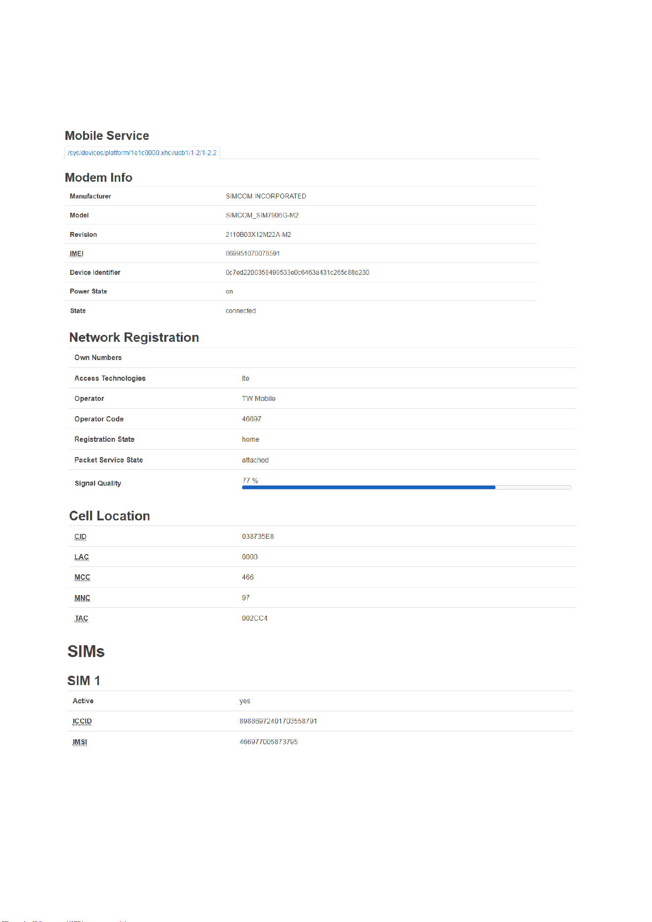
Mobile Service
In Mobile Service, it shows the information of the Modem, Network Registration, Cell Location and SIM card.
Firewall
Displays current firewall zones and rules.
41
Shows active connections and NAT rules.
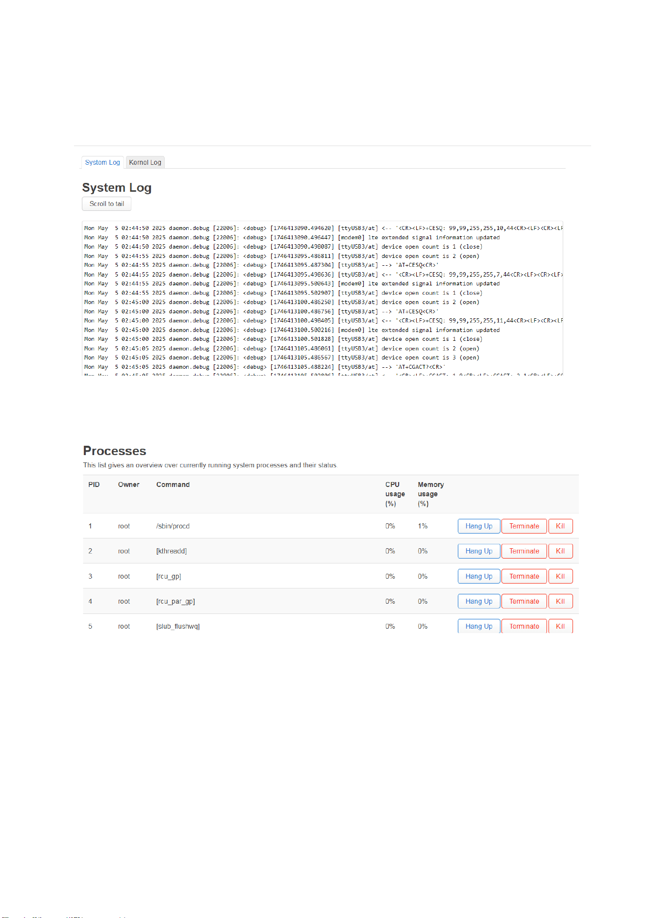
System Log
Shows the system’s kernel and service logs.
Helpful for debugging service behavior and startup issues.
Processes
Shows currently running processes with PID, memory usage, and CPU usage...
This list gives an overview over currently running system processes and their status.
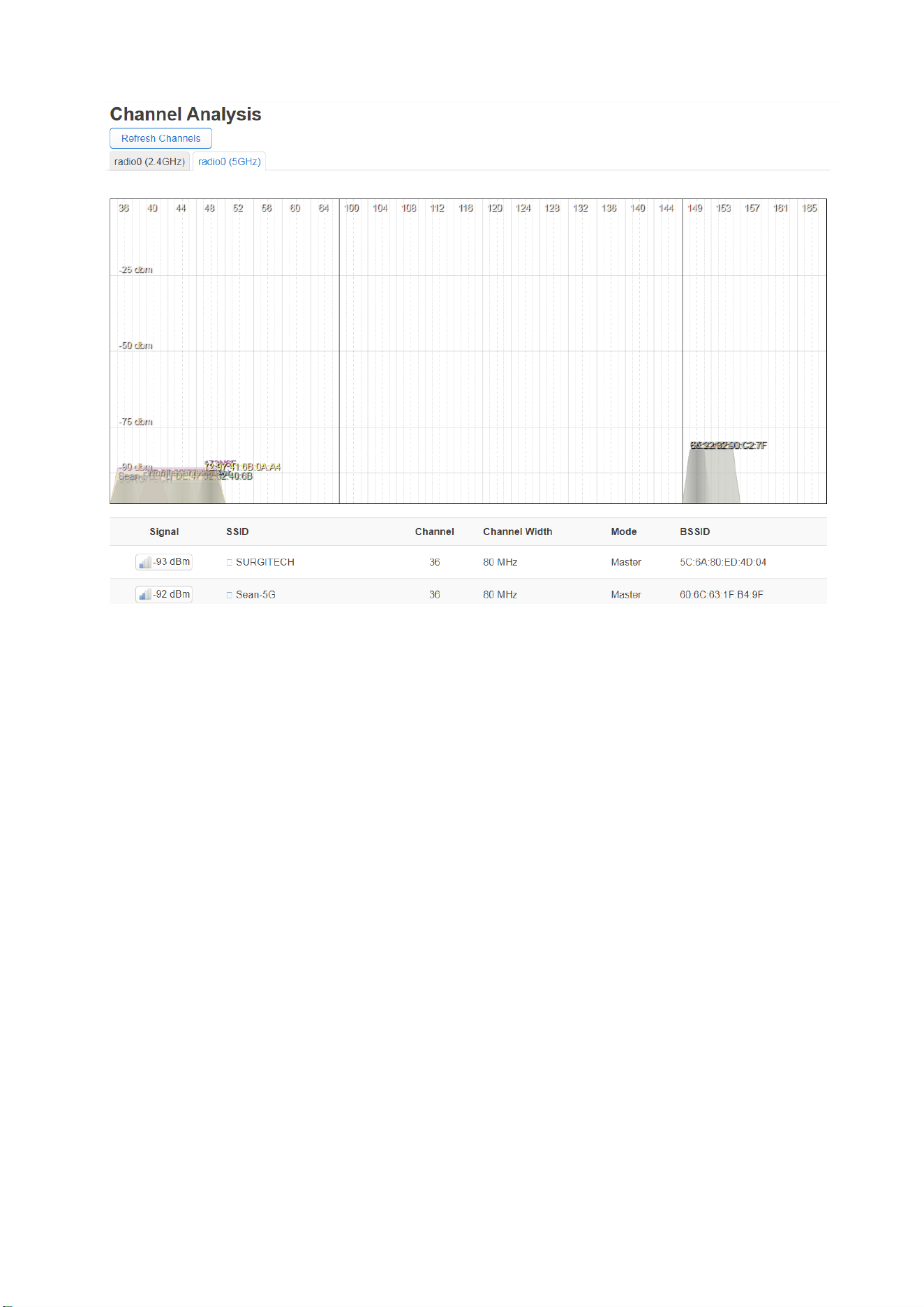
Channel Analysis
Shows the current channel detected by the Wi-Fi radios.
It helps to understand the radio network status while you need to optimize the WLAN performance.
42
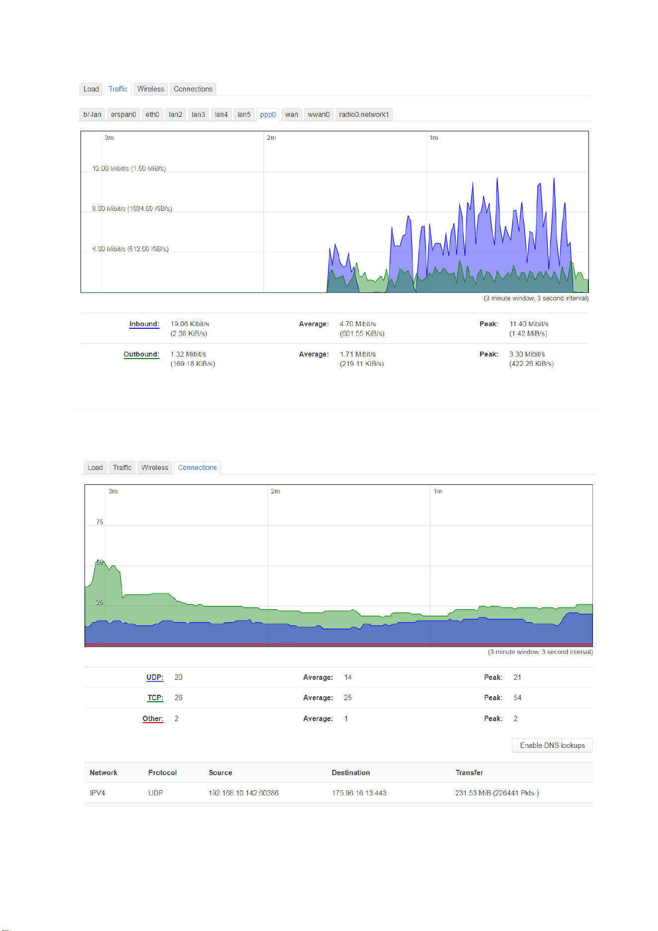
Realtime Graphs
Show the system Load, network Traffic usage, Wireless and Connection load graphs in real-time.
Helps visually monitor resource load and interface throughput.
Example of the 4G LTE network Traffic usage:
43
Example of the Connection usage and source device:
44
3.4.2 SYSTEM
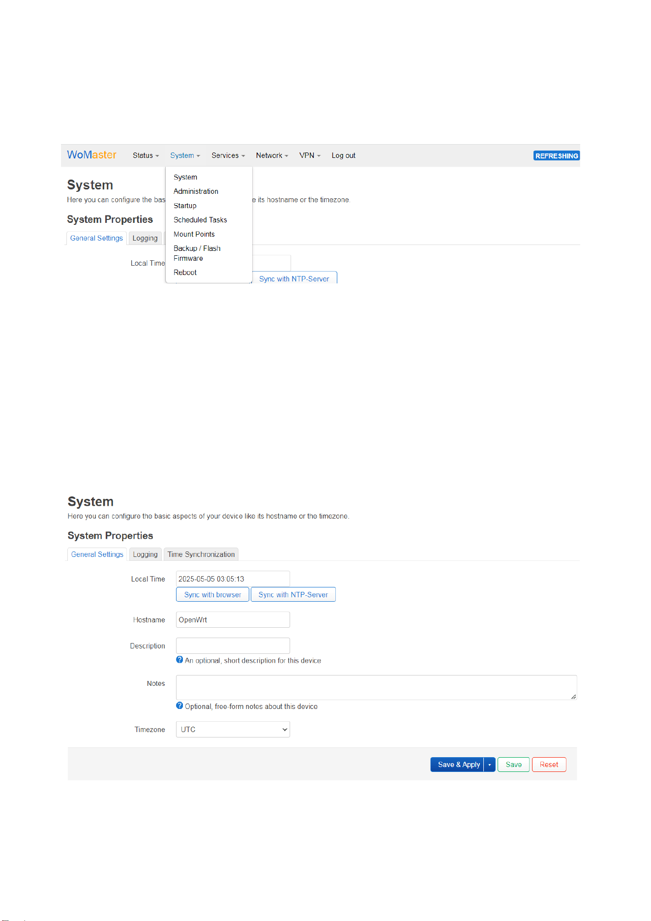
3.4.2.1 System → System
System Properties allows you to configure Device Settings, Log setting and NTP Server settings.
• General Settings: It shows the Local Time and allow you to select “Sync with browser” or “Sync with NTP
Server”. Set hostname, Description and “Notes” about this device. And configure the Timezone.
• Configure Logging settings
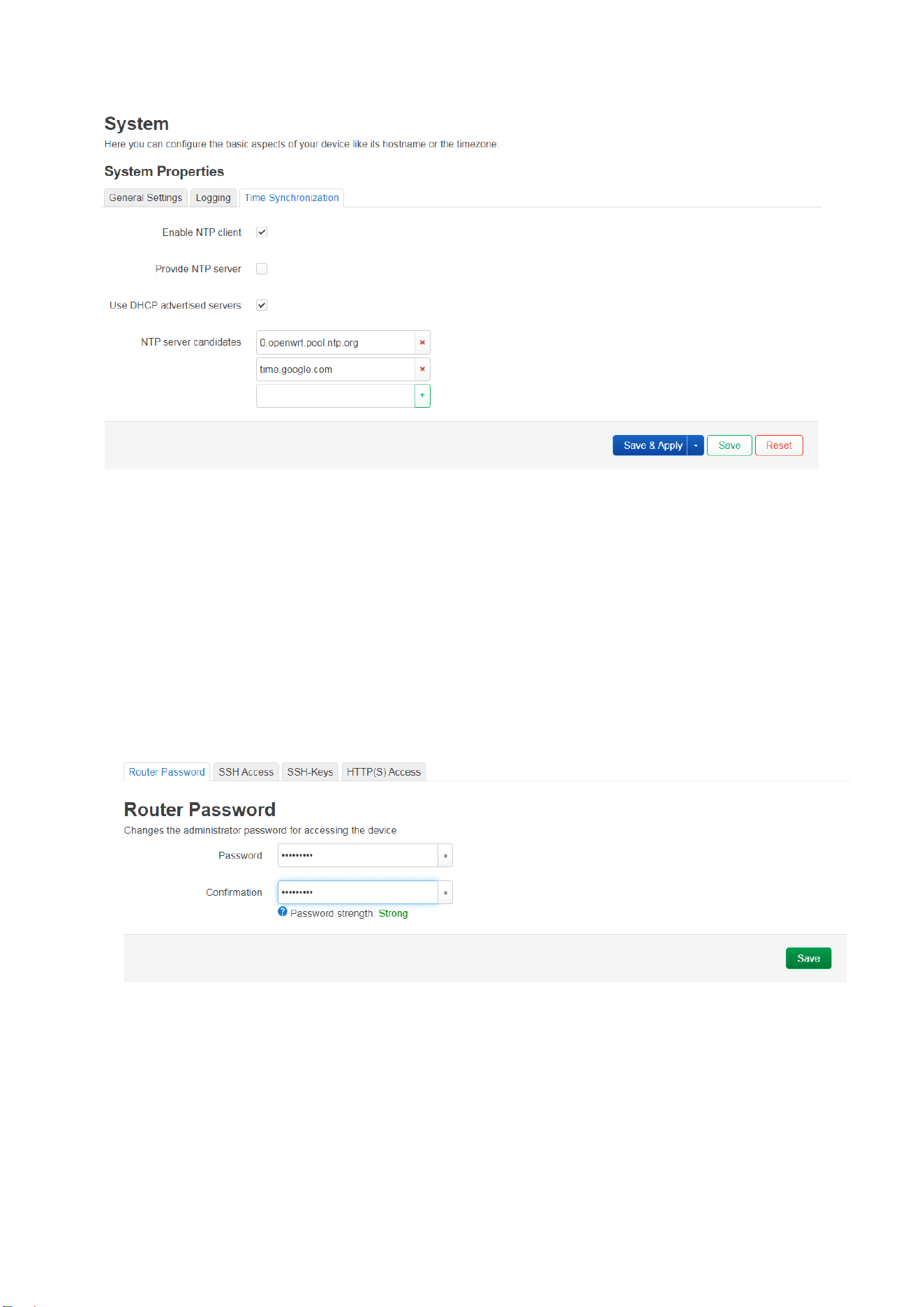
• Configure the NTP Server Setting. Default is NTP Client. You can add your prefer NTP server here. Ex:
time.google.com (Google NTP Server)
45
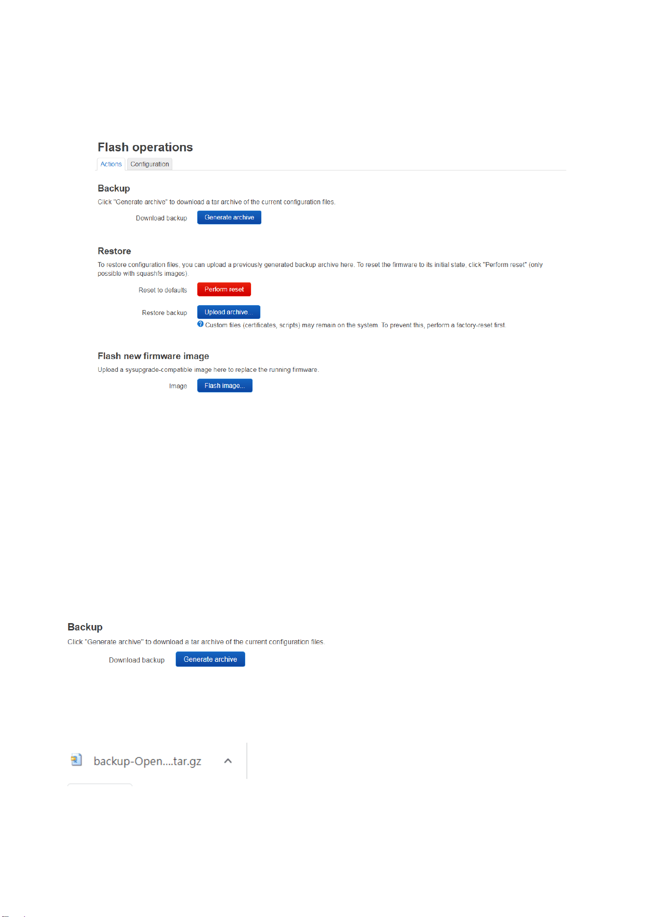
3.4.2.2 System → Administration
• Router Password: Change web GUI and SSH password. Password Strength indicates whether the password
you enter is strong enough or not.
• SSH Access: Set SSH access settings. You can assign the given interfaces. Select “unspecified” means all
interfaces.
• SSH-Keys: Upload and manage SSH public keys
• HTTP(S) Access: Enable automatic redirection of HTTP requests to HTTPS port.
46
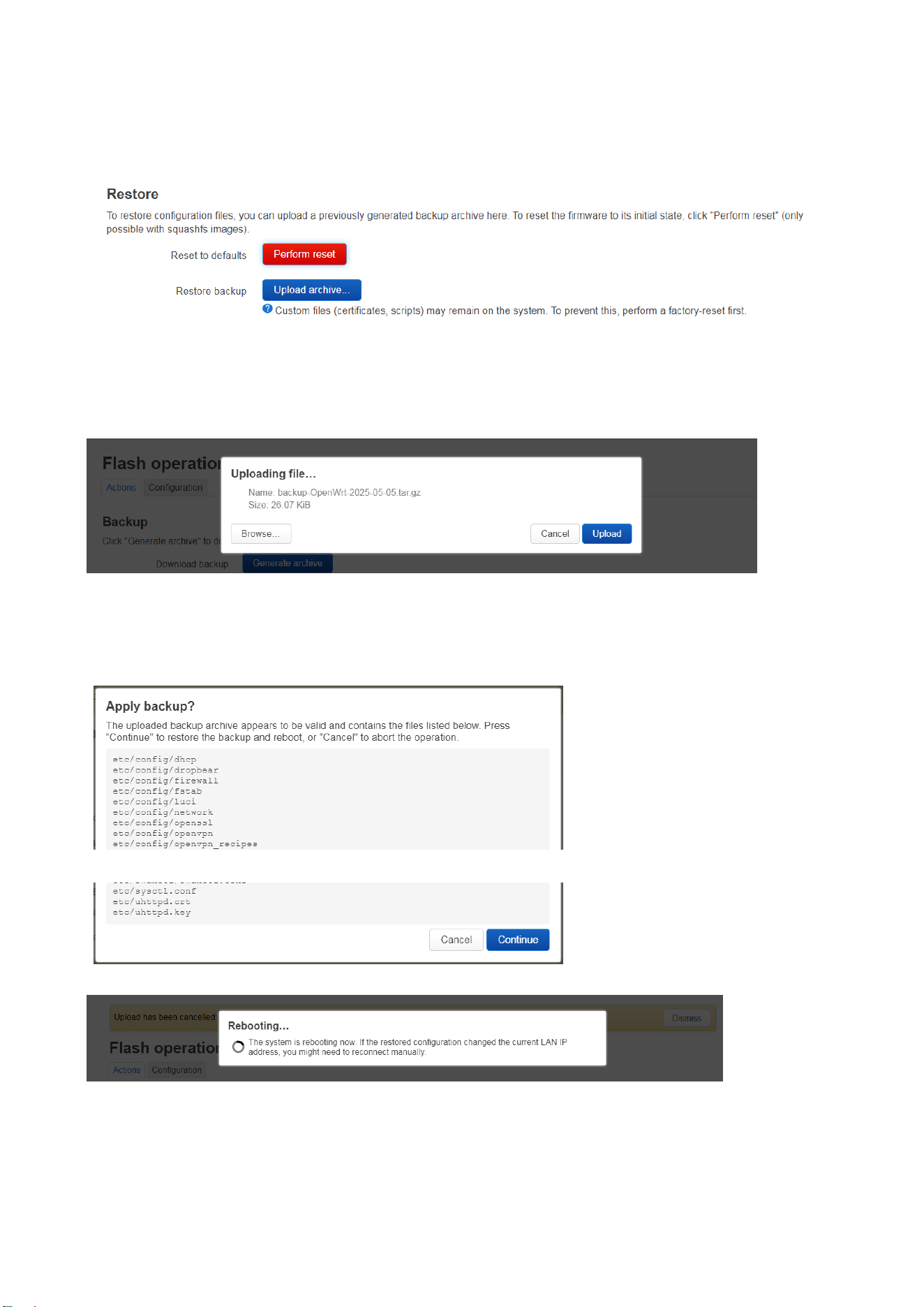
3.4.2.3 System → Flash Operation
The Flash operations allow you to backup/restore the configuration file and firmware upgrade.
• Backup: Download or upload configuration backups
• Restore: Restore settings from a backup file. Perform Reset to default.
• Flash new firmware image: (with or without keeping settings)
◼ Flash Operation: Backup/Restore
To Backup the configuration file. Execute the “Generate archive” command and you will see a configuration file
automatically generated at the bottom of the web GUI screen. This file is usually saved in your default Download
folder.
Example: A back file name: “backup-OpenWrt-2025-05-05.tar.gz” is generated.
47
To Restore the configuration file from one device to the device. Execute the “Upload archive” command and you will
see a pop-up window for uploading file.
Browse the folder of the configuration file, ex: “backup-OpenWrt-2025-05-05.tar.gz”. You can see the file name on
the pop-up window. Click “Upload” to restore the configuration file to the router.
A pop-up window will ask confirm “Apply backup?” Press “Continue” to restore the configuration file and the router
will reboot automatically.
48
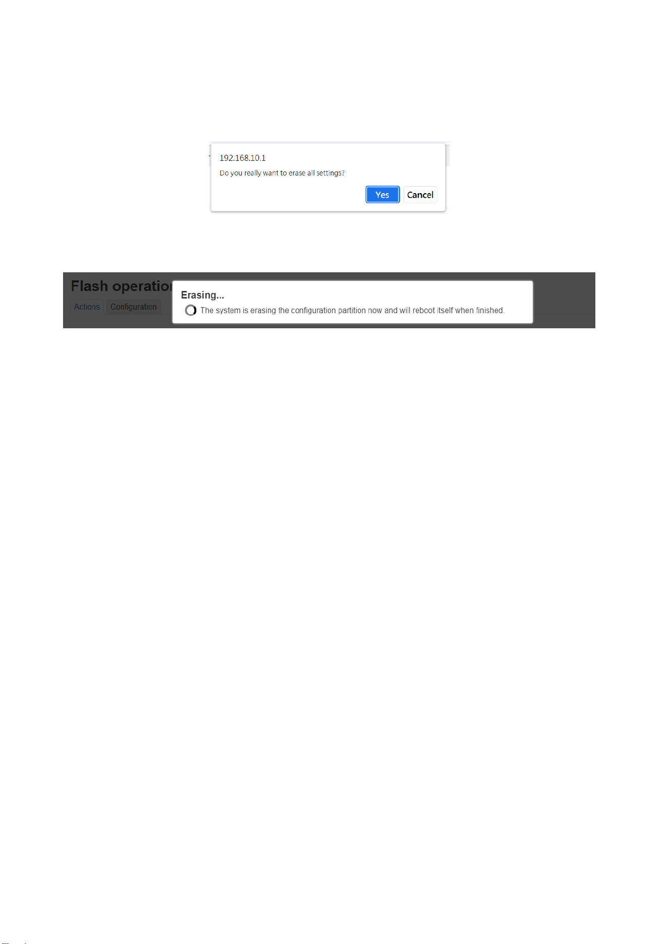
◼ Flash Operation: Reset to Default
Click “Perform reset”. A pop-up window will ask you “Do you really want to erase all settings?”
Click “Yes”. The router will erase the configuration and will reboot itself with the default configuration.
If the system cannot automatically reconnect to the web GUI due to the removal of the IP and settings, please
reconnect to the web GUI with the default IP Address.
49
◼ Flash Operation: Firmware Upgrade
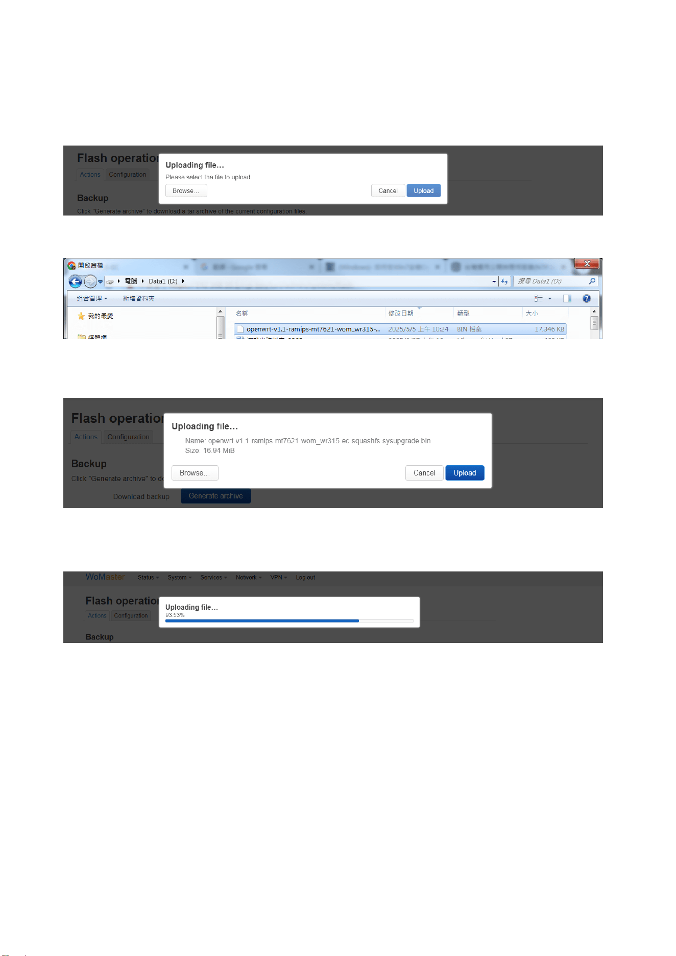
Click “Flash image…”, you can see the below popup window.
Then click “Browse…”, browse the folder of the firmware file and select the correct new firmware image file.
After selected the file, you will be the file name at the popup window.
Click “Upload”, the file will be uploading…
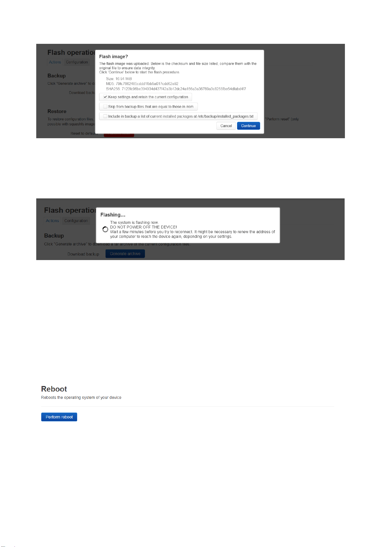
After uploaded, you can keep current configuration by selecting the “Keep Settings and retain the current
configuration”.
50
After “Continue”, you will see the Flashing… The system is flashing the image…
Warming!! DO NOT POWER OFF THE DEVICE while Flashing…!!
The router will automatically reboot after finished the progress.
Note: Since OpenWrt is based on an open system architecture, system settings may be altered after a firmware
update. If an external device (such as a 4G or Wi-Fi module) fails to activate properly, try restarting the device or
modifying its settings, then apply and save the changes to reactivate it.
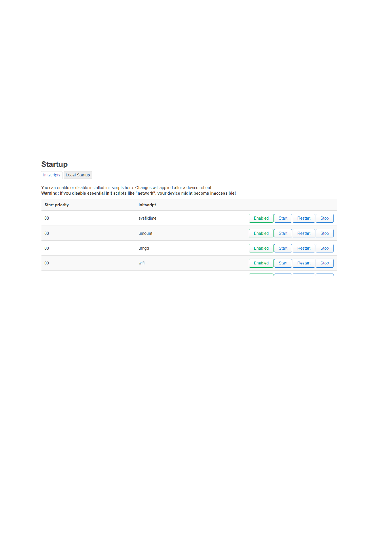
3.4.2.4 System → Reboot
Reboot the device manually.
51
3.4.2.5 Advanced Settings:
The OpenWrt system provides some advanced settings to change the router’s initial state. However, these functions
are only suitable for engineers who are familiar with the OpenWrt system.
◼ System → Startup
You can enable or disable installed init scripts here. Changes will applied after a device reboot.
• View and manage init.d scripts (boot-time services). Enable/disable services…
• Control startup order and status.
Warning: If you disable essential init scripts like "network", your device might become inaccessible!
◼ System → Scheduled Tasks (crontab)
• Add scheduled jobs using cron syntax
• Useful for automating tasks like reboots, interface resets, or logging
◼ System → Mount Points
• Configure external storage (USB drives, SD cards)
• Set up automatic mounting of storage volumes
52
3.4.3 Network
3.4.3.1 Interfaces
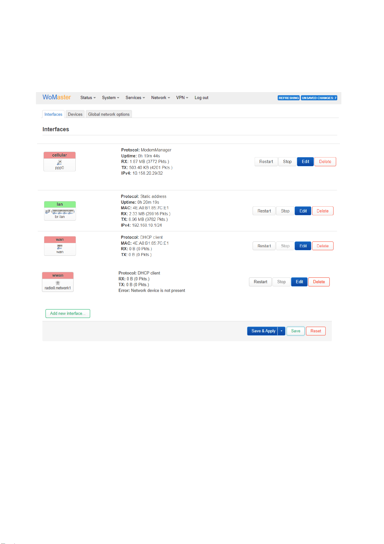
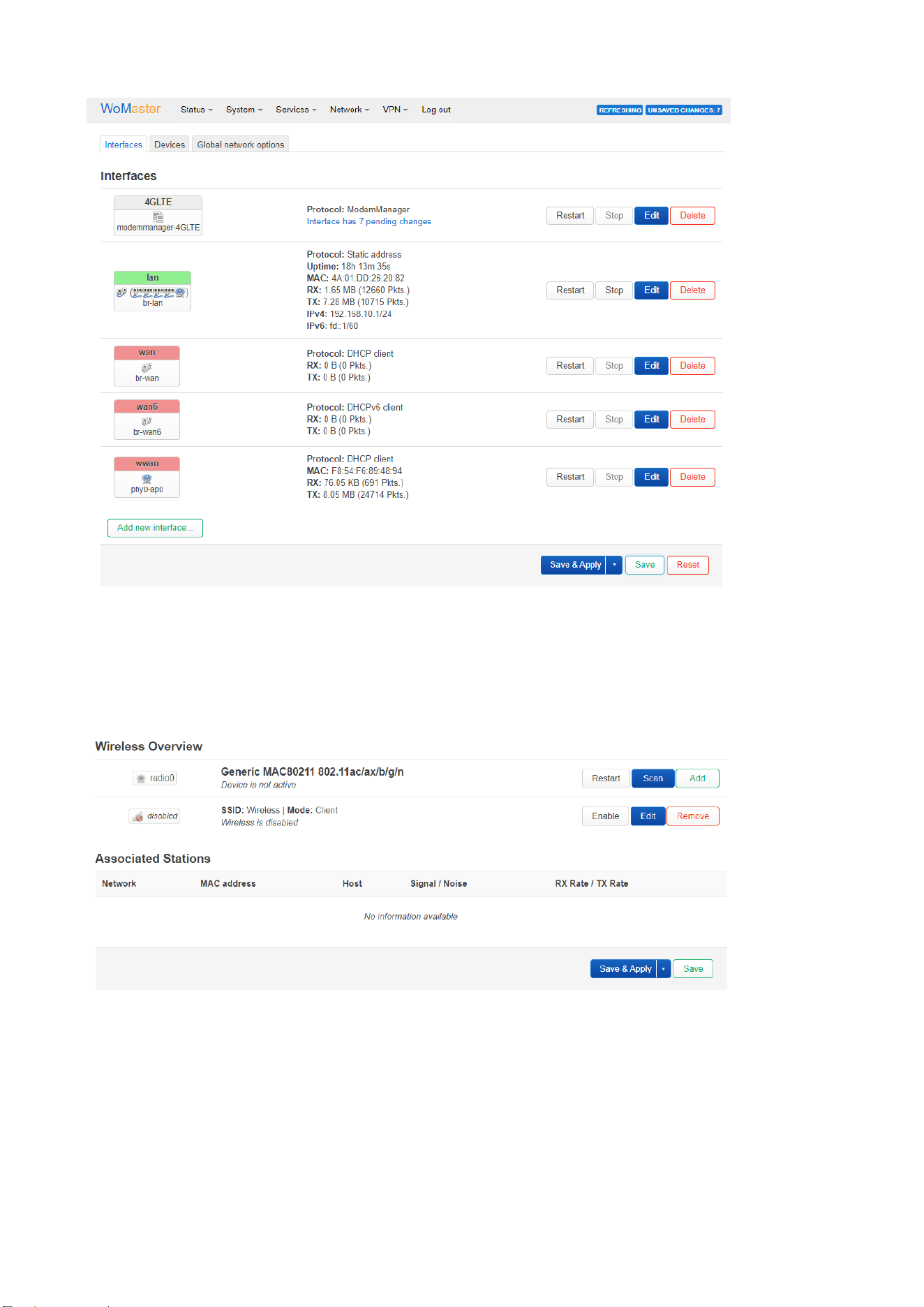
The router has created the existed interfaces of the WR315G-2C-LTE6-GAX-EC, such as Cellular(4G LTE), lan
(Ethernet-LAN, physical port 2/3/4/5), wan(Ethernet-Wan, physical Port 1), and wwan (Wi-Fi 6 client mode) as below.
Note: “wan6” is the IPv6 configuration of WAN interface. It is usually not used.
The “Add new interface” allows you to add additional interfaces, or recreate an interface after you have deleted it.
Click “Save & Apply” after you changed the settings.
Note: The Router has already created the current user interface for you. If you want to delete or add other interfaces,
please be careful and be familiar with the working principle of OpenWrt operating system. If you delete it by mistake
and don't know how to restore it, you can use reset to default to restore the factory settings.
The following page explains the meanings of each interfaces.

53
◼ Interface: Cellular
The Cellular interface displays the status of the mobile broadband (4G/5G) connection used by the device to access
the internet. It is typically used as a primary or backup WAN interface, especially in remote or mobile environments.
This status panel provides real-time information about the cellular connection:
• Interface Name: Shown as ppp0, this is the system-assigned name for the point-to-point (PPP) cellular
connection.
• Protocol: Indicates the connection manager used, such as ModemManager, which controls and
communicates with the cellular modem.
• Uptime: Shows how long the current cellular session has been active.
• RX / TX: Displays the amount of data received (RX) and sent (TX) over the cellular network, along with the
number of packets transferred.
• IPv4 Address: Shows the assigned IP address and subnet, typically used for routing cellular traffic.
Control buttons on the right allow the user to:
• Restart the interface (reconnect),
• Stop the interface (disconnect),
• Edit configuration settings, or
• Delete the interface (use cautiously).
Warming: Do NOT delete this interface unless you use other non-default 4G/5G cellular modules and you are quite
familiar with how OpenWrt works. Generally, we do not recommend or authorize users to replace the 4G module by
themselves. Any self-replacement of the hardware module is not covered under the product warranty or support
services. The manufacturer shall not be held liable for any damage or malfunction resulting from unauthorized
hardware modifications.
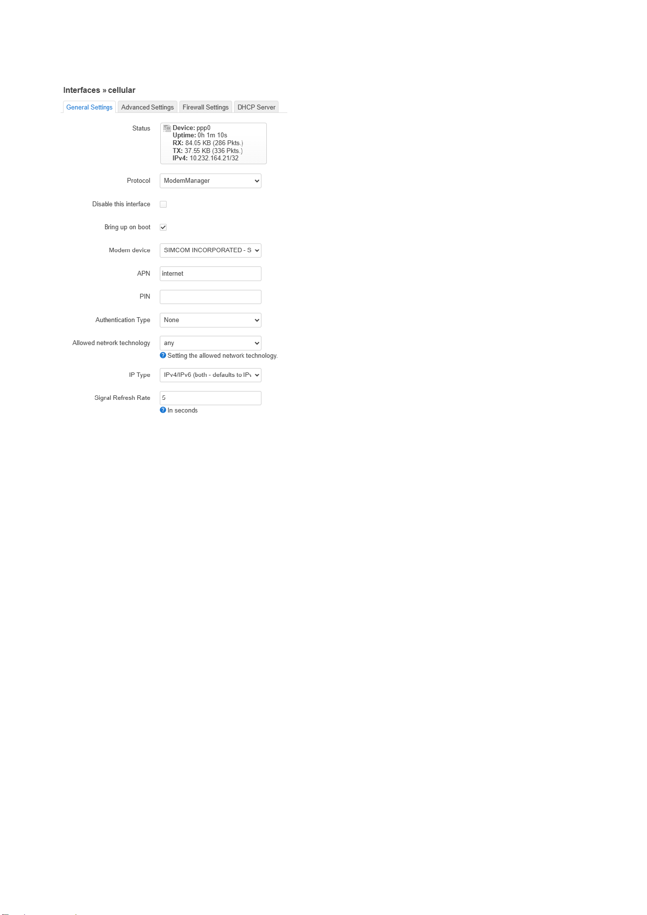
Edit interface
After clicking "Edit" on a Cellular interface (usually named wwan, 4G, ppp0, or similar), you'll be taken to a
configuration page that allows you to modify various connection and network parameters.
The page is mainly used to modify the APN, Disable the interface if you do not use 4G/Cellular...etc.
The default APN name is internet which is popular used in worldwide.
You can type SIM PIN number (password) if it is configured, but, do not allow you to modify the PIN number.
54
The cellular interface is enabled in default setting, while it will start the connection automatically on boot.
This is where you set the main connection parameters:
• Protocol: ModemManager
• Modem device: Automatically detected (e.g., SIMCOM… module)
• APN(Access Point Name): The APN provided by your mobile operator, default: internet
• PIN: SIM card PIN (if enabled) (Modify the SIM Card PIN is not supported)
• Authentication:
o Options: None, PAP, CHAP
o Some networks require this for authentication.
• Allowed Network Topology: any
• IP Type:
o IPv4, IPv6, or IPv4v6
o Select based on what your mobile operator supports.
• Signal Refresh Rate: 5 (in seconds)

55
◼ 3.4.3.2 Interface: lan/wan
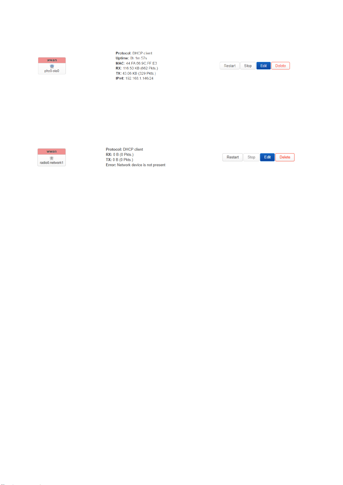
This section shows the status of the LAN (Local Area Network), which connects local devices (like PCs or IoT nodes)
to the router. And the WAN (Wide Area Network) interface, used for internet access via a wired uplink (e.g., fiber,
DSL, cable modem).
Displayed information of the LAN interface includes:
• Interface name (e.g., br-lan) – This indicates a bridge interface that combines multiple physical ports (e.g.,
LAN port 2, port 3, port 4 and port 5) into one logical network.
• Protocol – The IP assignment method. Ex: Static address indicates the Lan interface has a fixed IP.
• Uptime – How long the interface has been active.
• MAC address – Unique hardware identifier for the interface.
• RX/TX – Received and transmitted data, showing current traffic flow.
• IPv4 address – The IP address assigned to the interface (default: 192.168.10.1). The IP is usually acts as the
default gateway of the connected devices.
The WAN interface connects the router to the internet or an upstream network. It commonly uses DHCP client mode
to obtain an IP address automatically from the internet provider.
Displayed information of the WAN interface includes:
• Interface Name: wan
• Protocol: DHCP client. It tries to get an IP address from your internet provider (or upstream router).
• MAC: The hardware address of the WAN interface.
• RX/TX: Received and transmitted data. 0B(0 pke/s) means No data has been received or sent yet. This may
mean the WAN cable is unplugged or the upstream device is down.
• IPv4: The IP address of this interface. Not shown — likely because no IP address has been obtained yet.
Each interface includes control buttons:
• Restart – Re-establish the connection.
• Stop – Temporarily disable the interface.
• Edit – Change settings like IP, DNS, or protocol type.
• Delete – Remove the interface configuration (for advanced users only).
Note: The router has one wan interface port 1 and lan interface port 2/3/4/5 by default configuration.
Note: “wan6” is the IPv6 configuration of WAN interface. It is usually not used.
56
◼ 3.4.3.3 Interface: wwan
The WWAN (Wireless Wide Area Network) interface allows the device to connect to an external Wi-Fi network as a
client, functioning similarly to how a laptop or smartphone connects to a hotspot or access point. This interface is
typically used when a wired WAN or cellular connection is unavailable.
By default, this interface is disabled to prevent unintentional conflicts with other network interfaces.
N
ote: It is strongly recommended to use only one wireless interface for external network access at a time. Using both
the WWAN interface (Wi-Fi client) and 4G cellular as uplinks simultaneously can cause routing conflicts. This may
lead to unpredictable network behavior, as the system may be unable to clearly determine which interface to use for
outgoing traffic.
Key Details Shown in the Status Panel:
• Interface Name: Represents the logical name of the Wi-Fi WAN connection (e.g., wwan).
• Associated Device: Indicates the internal wireless radio (e.g., radio0) used for the connection.
• Protocol: Usually set to DHCP client, meaning the device will automatically request an IP address from the
upstream Wi-Fi network.
• MAC Address: The MAC address of the radio module.
• RX/TX: Shows the amount of data received and transmitted over the wireless link. If values are zero, the
connection may not be established.
• Error Message: If the message “Network device is not present” appears, it means the wireless hardware is
either disabled, unconfigured, or failed to connect. (Not Enable State)
• IPv4: The IP address of the interface. Obtain the IP address from the AP in DHCP client mode.
Control Options:
• Restart – Attempts to reconnect to the Wi-Fi network.
• Stop – Disables the wireless client connection.
• Edit – Opens configuration settings to set SSID, password, or network mode.
• Delete – Removes the WWAN interface configuration (for advanced users only).
57
◼ 3.4.4.4 Add new Interface
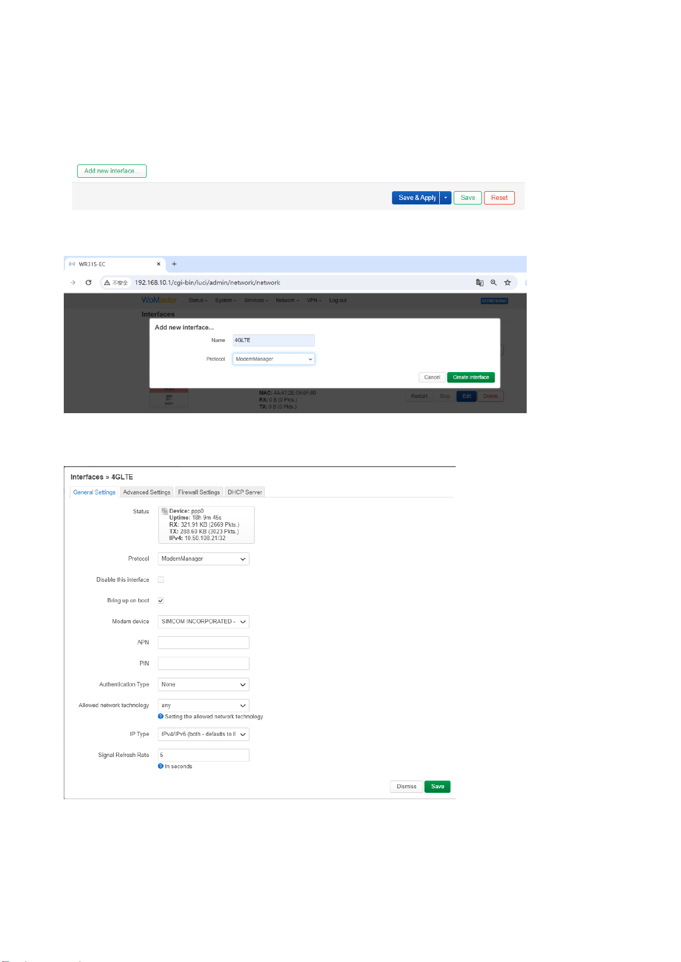
The following example demonstrates how to restore a 4G network interface in case it is accidentally deleted. This
procedure is provided solely for recovery purposes and should not be used for general configuration or hardware
modifications.
Click on “Add new interface”.
Set parameters in the pop-up window. Enter the name and select “ModemManager” from the dropdown menu.
Click on “Create interface”. The following window will pop up.
Then type the APN…settings.
After configured, then click on “Save”, it will return to the Interfaces page.
58
3.4.3.2 Wireless(Wi-Fi)
Here is the web interface for you to configure Wi-Fi settings.
In initial state, the Wi-Fi interface is disabled. And there is no associated station.
Click “Scan” to scan the Wi-Fi network over the air. Below screen shows part of the wireless network the router has
discovered…

59
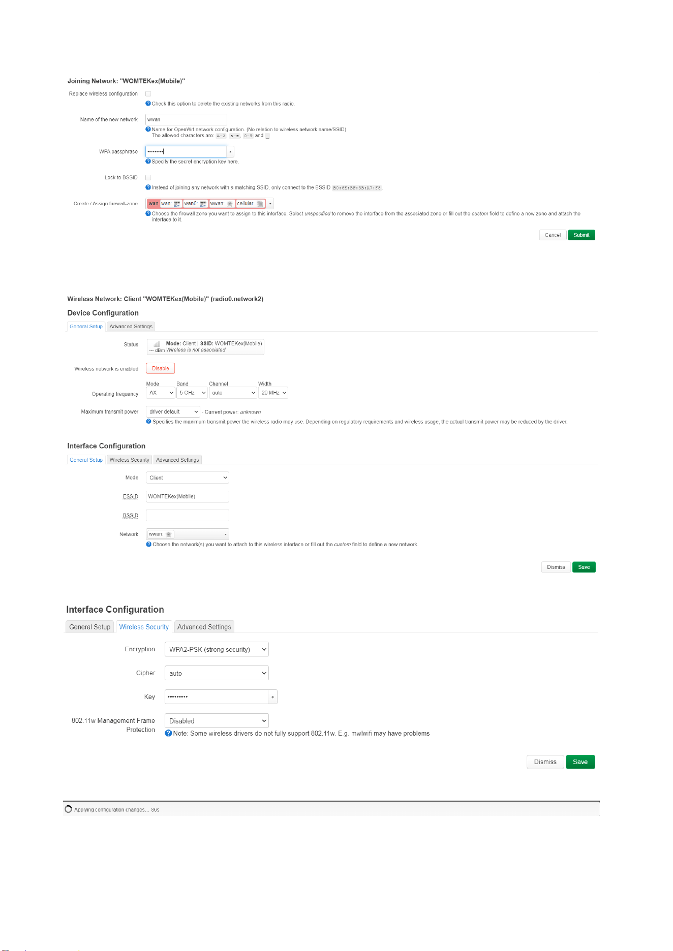
Select the target AP you want to connect and click “Join Network”.
60
Type the WPA password, and click “Submit”. Then the Device Configuration pop-up window appears and you can
configure the Wi-Fi parameters here.
Wireless Security setting:
After configured, click “Save” to apply the settings.
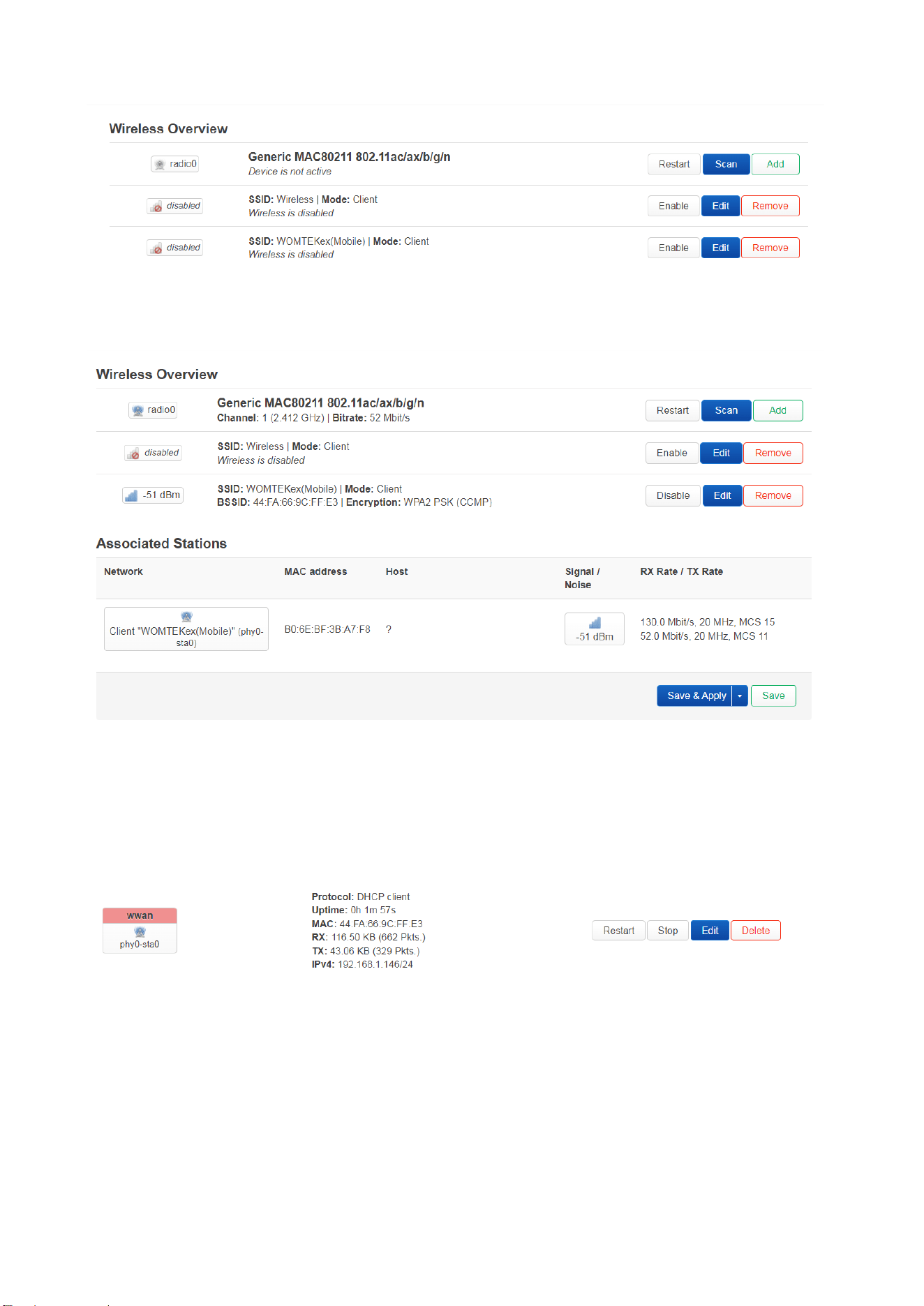
After applied the settings, you can see the SSID you connect in the Wireless Overview.
61
Click “Enable” of the interface with SSID you select. While you see the link quality, BSSID and Encryption info, it
means you already connect to the target AP. You can also see the Associated Station table on the same page.
In Associated Stations list, you can see the wireless network you join, signal quality, RX/TX rate and bandwidth
information. Click “Save&Apply” to permanently activate.
To see the Wi-Fi information, you can also find the changed in the Network Interface and STATUS overview.
Network Interface: wwan
62
3.4.4.3 Routing
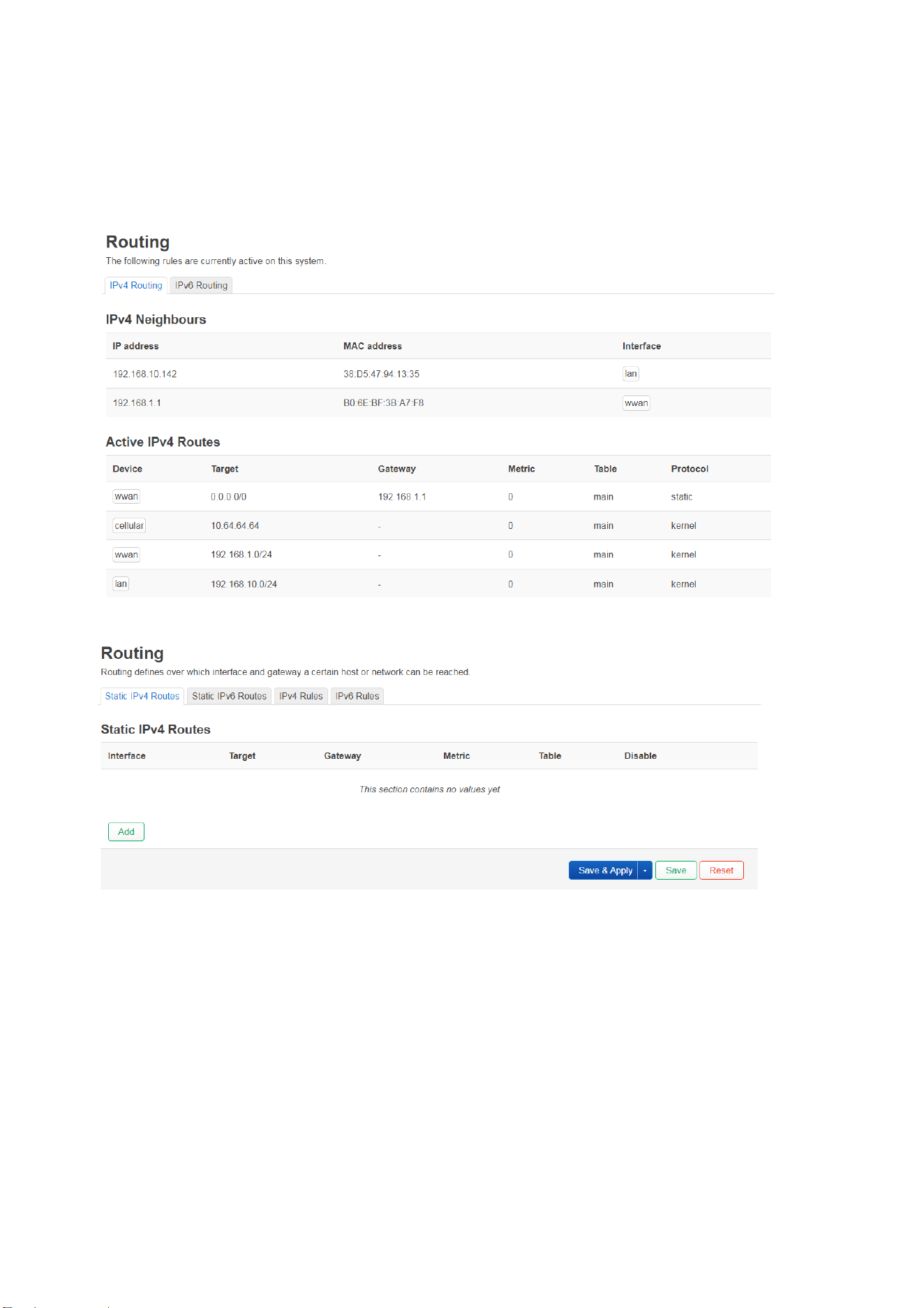
Our device has preset LAN to wwan(Wi-Fi) /cellular(4G LTE) routing rules. You can find it on the STATUS-Routing
page. If it is not enough for your use, you can add new rules here.
STATUS-Routing:
Click “Add”, you can add new rules, but be careful not to conflict with each other.
63
3.4.4.4 DHCP and DNS
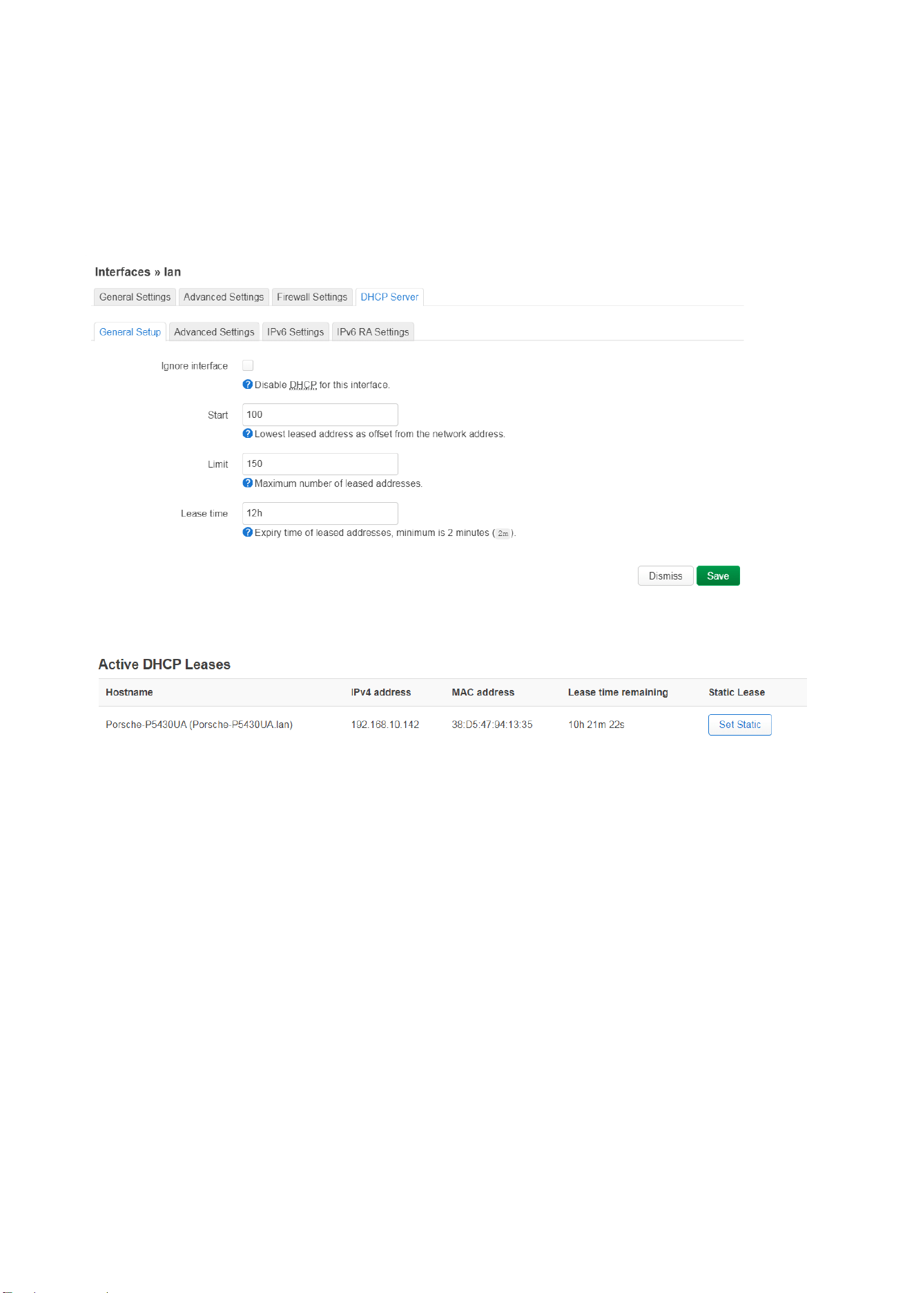
The DHCP Server feature is enabled by default configuration. You can find this in DHCP Server feature set of the
Interface-Lan, as shown in below screen. The default IP of the lan interface is 192.168.10.1. It means the IP poll is
started from 192.168.10.100 to 192.168.10.150. The default DHCP lease time is 12h.
Interface – lan – edit – DHCP Server
In Status Overview, you can find the connected clients and the IP address they obtained.
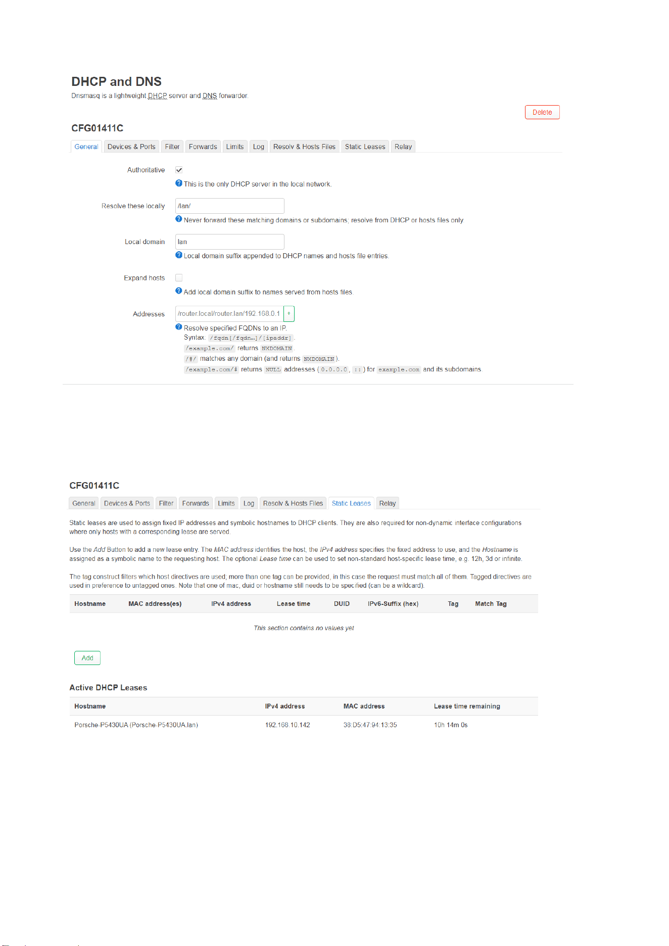
This is the DHCP and DNS configuration page in OpenWrt’s LuCI web interface, where the system is using Dnsmasq
as a lightweight DHCP server and DNS forwarder. Here’s a breakdown of what each setting means:
64
In General setting, the Authoritative is Checked. This tells Dnsmasq to act as the only DHCP server on the local
network. If a device requests an IP and isn't known, Dnsmasq will respond definitively (rather than ignoring the
request). The Resolve these locally and Local domain are applied to lan.
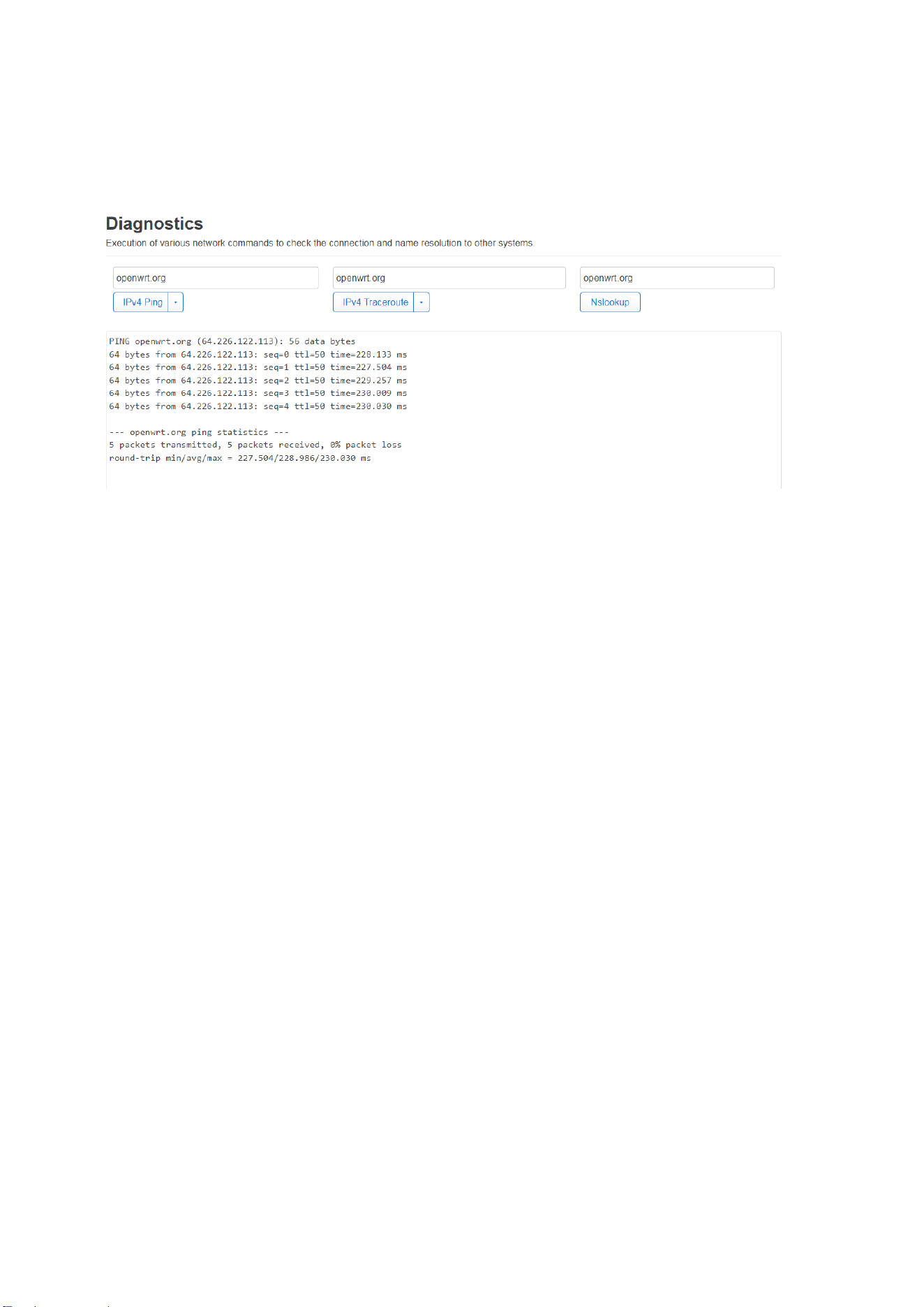
In Static Lease, you can assign specific MAC to specific host. You can also configure DHCP Relay in Relay setting.
65
3.4.4.5 Diagnostics
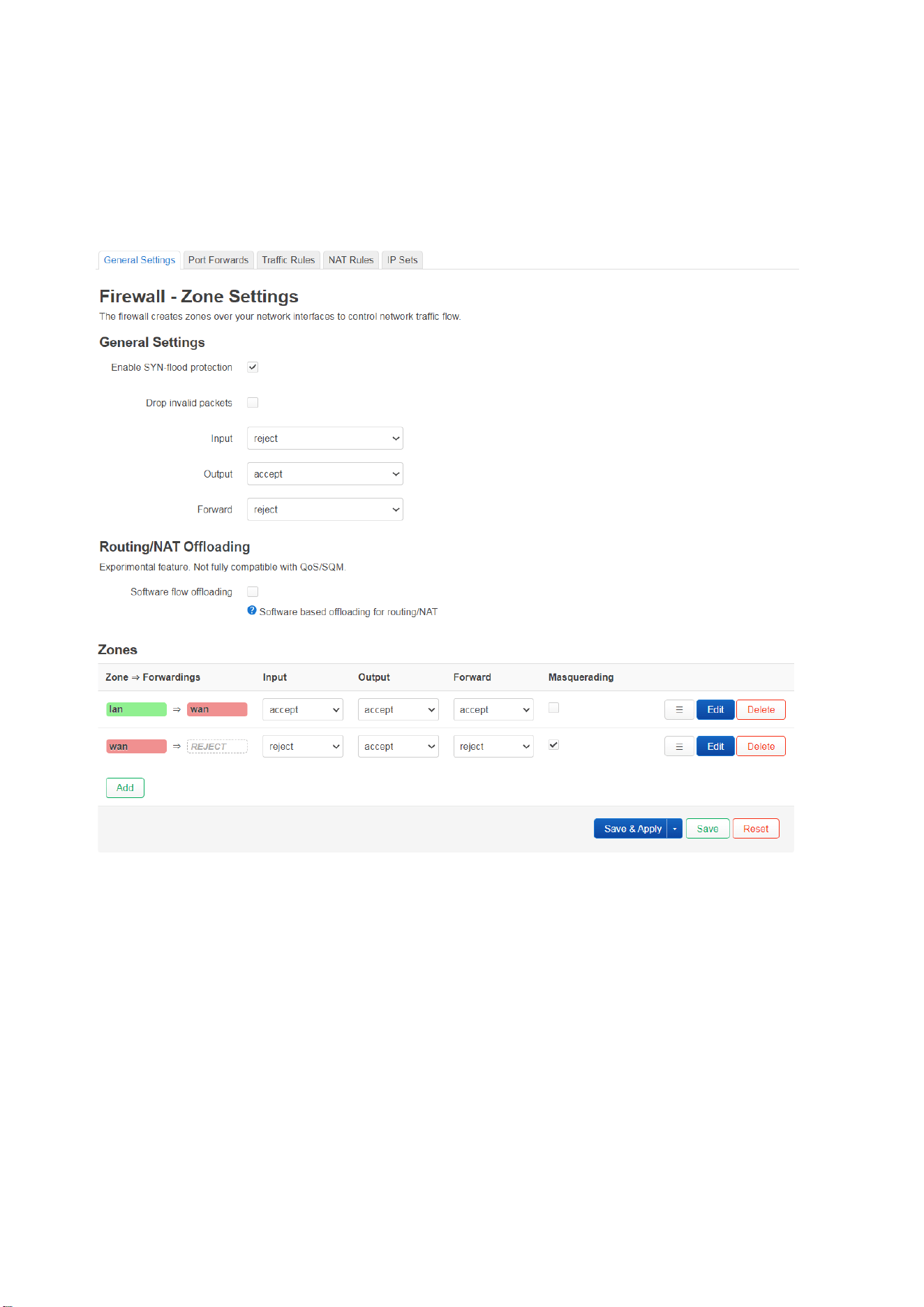
This section is used to test network connectivity and DNS resolution from the router itself. It provides simple but
essential tools to troubleshoot network issues. Type the target IP address and the tool to diagnostic.
◼ IPv4 Ping
Send Ping (ICMP echo requests) to the specified host. It is useful for checking connectivity and response time.
In the screenshot, “openwrt.org” is the target host, you can type target host’s IP address here. The responded
successfully with 0% packet loss and round-trip times between ~227–230ms.
◼ IPv4 Traceroute
Trace the path (hops) from the router to the target host. It helps diagnose routing issues or determine where a
connection might be failing.
◼ Nslookup
Perform a DNS lookup to check if the router can resolve a domain name to an IP address. It’s useful for checking if
DNS is working properly.
66
3.4.4.5 Firewall
The firewall feature manages traffic between network zones (e.g., LAN/WAN) using policies, NAT, and packet filtering.
This default firewall setting is very safe and is usually used in WAN interface (4G module, wireless wan, Ethernet-wan
to ISP). Prevent external access to the router or internal network. At the same time, allow intranet devices to access
the Internet normally through NAT.
Key sections include:
◼ General Settings
SYN-flood Protection: Checked.
Purpose: To prevent SYN flood attacks, which is a common DDoS (Distributed Denial of Service) attack method.
Attack method: Send a large number of TCP SYN packets in a short period of time, so that system resources are
exhausted and the connection cannot be established.
Once enabled, the router will limit or discard connection requests with abnormal frequencies to reduce the
risk of service interruption.
Drop Invalid Packets: Discards malformed or suspicious packets (e.g., invalid TCP flags).
Input: REJECT (blocks incoming traffic from the internet, ex: SSH, HTTP from internet).

67
Output: ACCEPT (allows outgoing traffic from the router).
Forward: REJECT (blocks traffic routed through the router between interfaces).
◼ Zones
Zones define security boundaries for interfaces (e.g., LAN, WAN). Each zone has policies for traffic flow:
Example Zones:
lan Zone:
Forwardings: wan (routes traffic to the WAN zone).
Policies:
Input/Output/Forward: ACCEPT (allows all internal LAN traffic).
Masquerading: Enabled (NAT: hides LAN IPs behind the WAN IP).
wan Zone (External Network):
Policies:
Input: REJECT (blocks incoming traffic from the internet, ex: SSH, HTTP from internet is blocked).
Output: ACCEPT (allows the router to send traffic to the internet).
Forward: REJECT (blocks traffic from WAN to other zones).
This design is very safe and is usually used in WAN interface (4G module, wireless wan, Ethernet-wan to ISP).
Prevent external access to the router or internal network. At the same time, allow intranet devices to access the
Internet normally through NAT.
Actions
Add: Create new zones (e.g., VPN, guest network).
Edit/Delete: Modify or remove zone rules.
◼ Routing/NAT Offloading
Software Flow Offloading: Optimizes routing/NAT performance by offloading tasks to the CPU.
Note: Marked as experimental; may conflict with QoS/SQM (traffic shaping).
Buttons
Save & Apply: Commit changes and reload the firewall.
Save: Store changes without applying.
Reset: Discard unsaved changes.
68
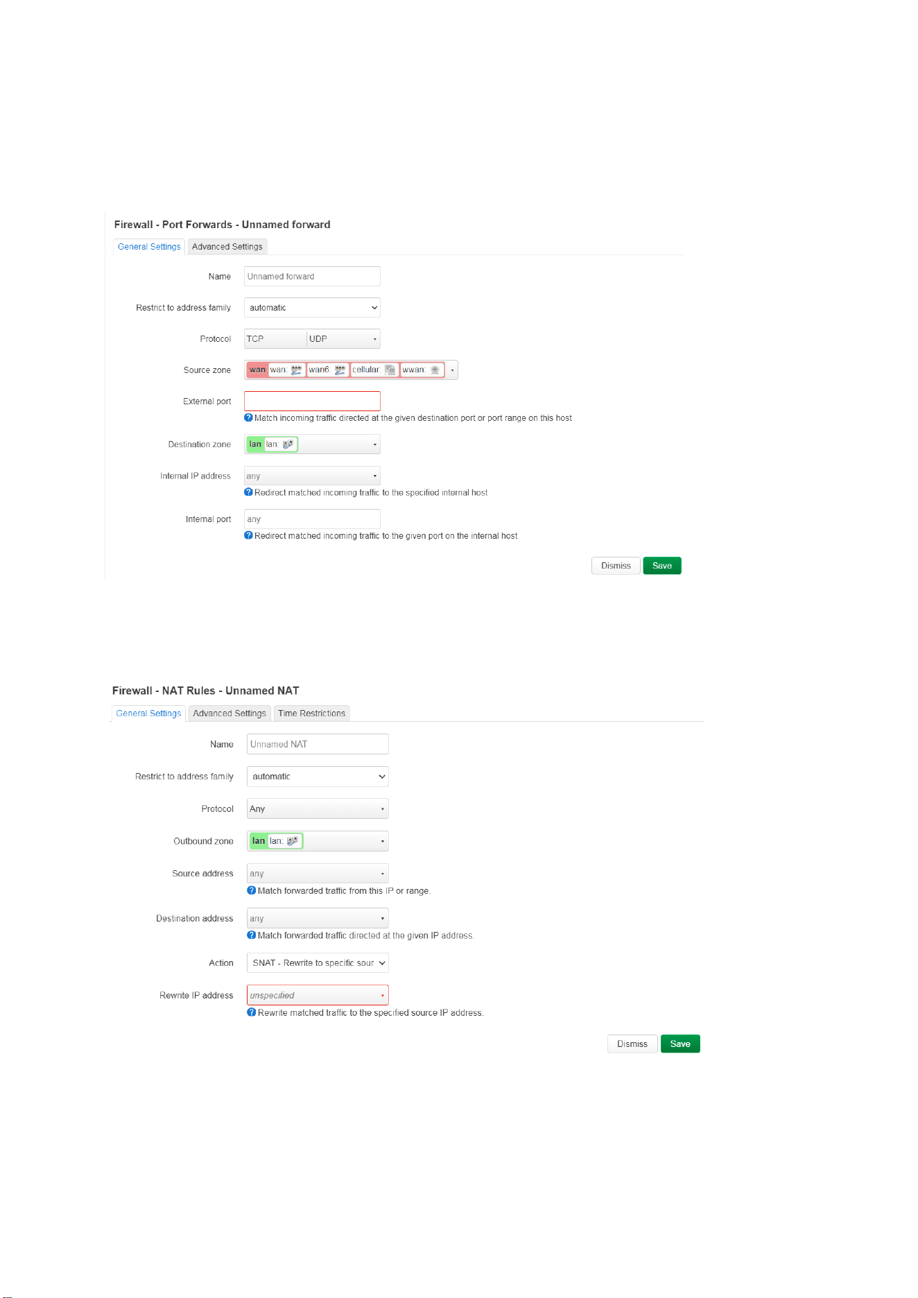
◼ Additional Tabs
Port Forwards: Redirect external traffic to internal services (e.g., hosting a server). You can specify the protocol
from the source zone (wan), external port to destination zoon (lan), internal IP address and port.
Traffic Rules: Define custom rules. Traffic rules define policies for packets traveling between different zones, for
example to reject traffic between certain hosts or to open WAN ports on the router.
NAT Rules: Configure advanced Network Address Translation.
IP Sets: Manage groups of IPs/networks for simplified rule creation.
When configuring NAT features in OpenWrt, it is important to understand how source and destination zones are

69
defined. The following table summarizes common NAT use cases and their typical zone settings:
Notes:
Masquerading is used for outbound traffic from LAN to WAN.
Port Forwarding handles inbound connections to internal services from the WAN.
Incorrect zone assignments may cause NAT to fail or create security vulnerabilities.
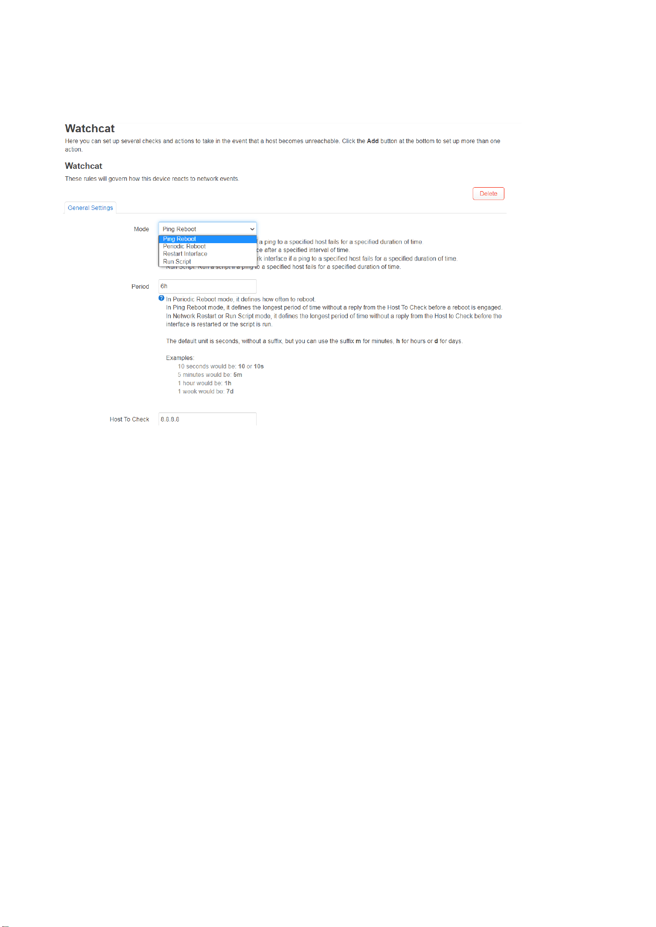
70
3.4.4 Services/Watchcat
Here’s an overview of Watchcat features in OpenWrt’s web UI (LuCI):
◼ Ping Reboot for connectivity monitoring
Ping-Based Monitoring: Continuously checks internet connectivity by pinging a reliable server (e.g., 8.8.8.8 or a
custom IP/domain).
Period: In Periodic Reboot mode, it defines how often to reboot.
Host To Check: Target IP address or hostname to ping. Ex: 8.8.8.8 (google)
Check (Ping) Interval: Adjust the frequency of connectivity checks (e.g., every 10 seconds). Examples: 10 seconds
would be: 10 or 10s, 5 minutes would be: 5m, 1 hour would be: 1h, 1 week would be: 7d
Force Reboot Delay: Applies to Ping Reboot and Periodic Reboot modes. When rebooting the router, the service
will trigger a soft reboot. Entering a non-zero value here will trigger a delayed hard reboot if the soft reboot were
to fail. Enter the number of seconds to wait for the soft reboot to fail or use 0 to disable the forced reboot delay
◼ Scheduled Periodic Reboots
Periodic Reboot: Forces the router to reboot at defined intervals (e.g., daily/weekly) to prevent memory leaks or
software instability.
Period: Configure specific reboot times (e.g., every 24 hours) or use cron-like syntax for precise scheduling.
Examples: 10 seconds would be: 10 or 10s, 5 minutes would be: 5m, 1 hour would be: 1h, 1 week would be: 7d
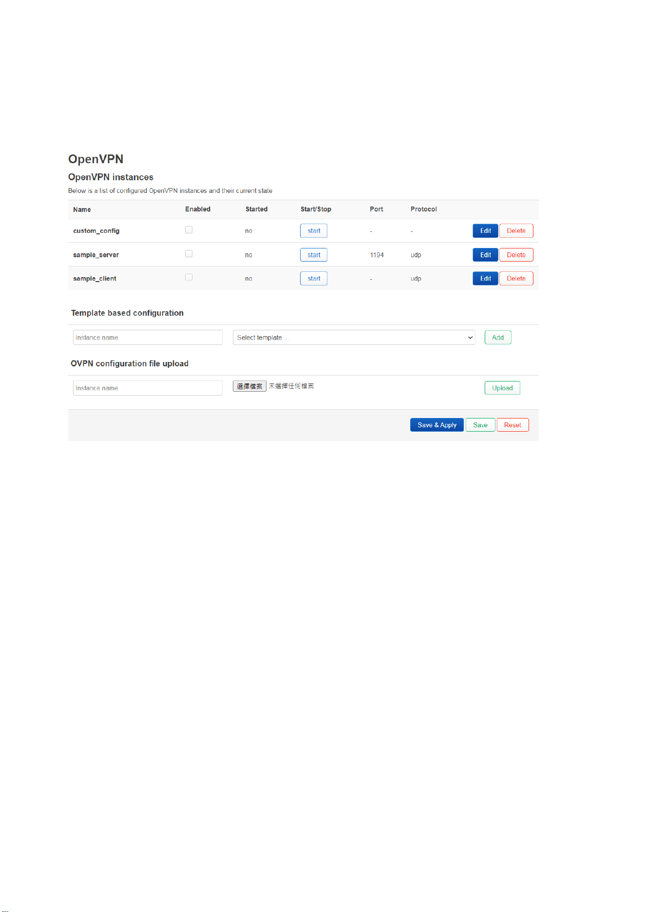
71
3.4.5 VPN
In UCLI web interface, it provides the OpenVPN.
For IPSec or others, please use SSH to configure.
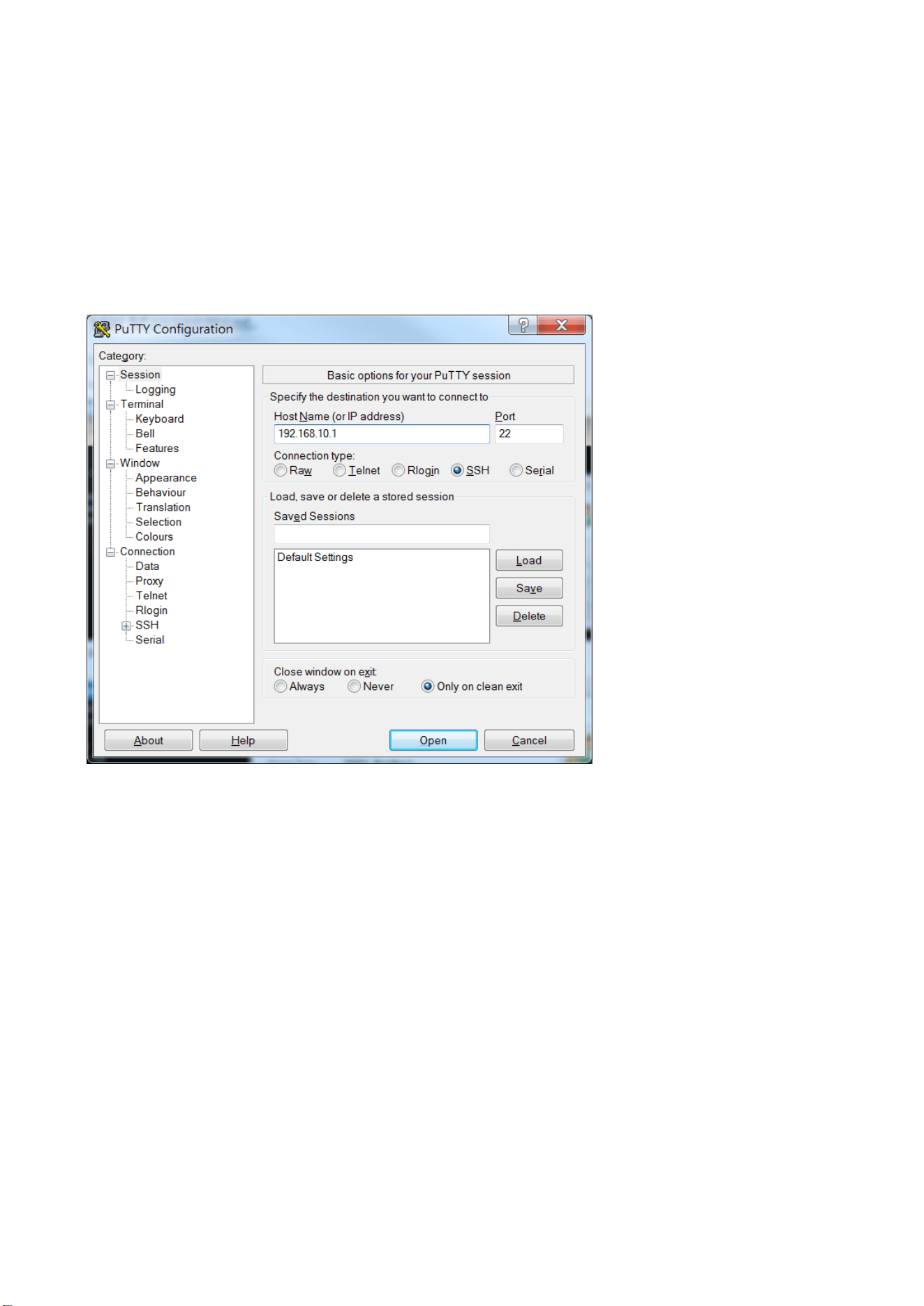
72
4. SSH Management
4.1 Login the router through SSH
There are both paid and free SSH terminal software available online, for example Putty, OpenSSH, XShell,
MobaXterm…etc. Below is an example by using PuTTY.
Open SSH Terminal Tool, type the IP address and SSH port of the router. Ex: 192.168.10.1, port 22
Enter username:root
Enter Password:root (default)
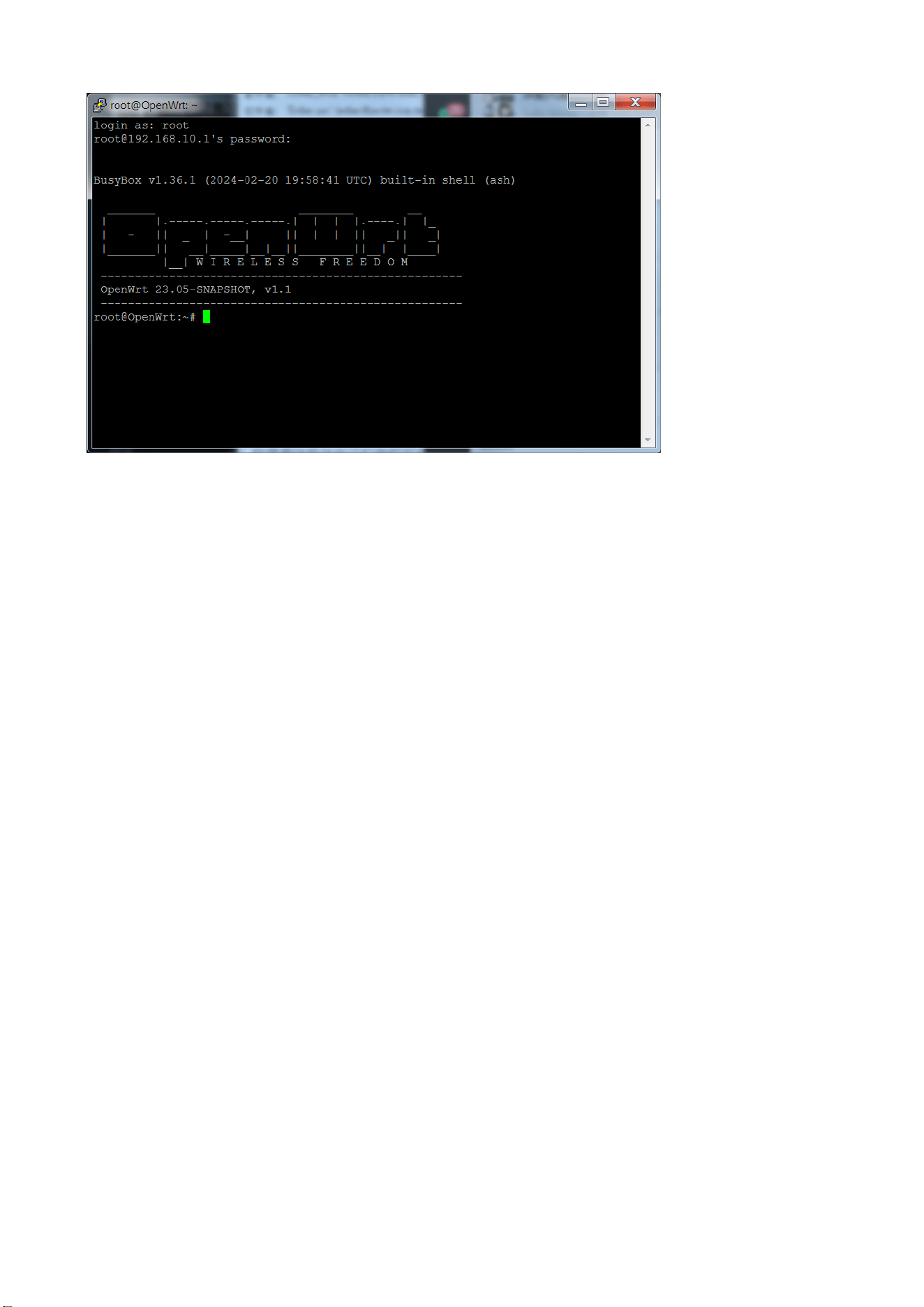
73
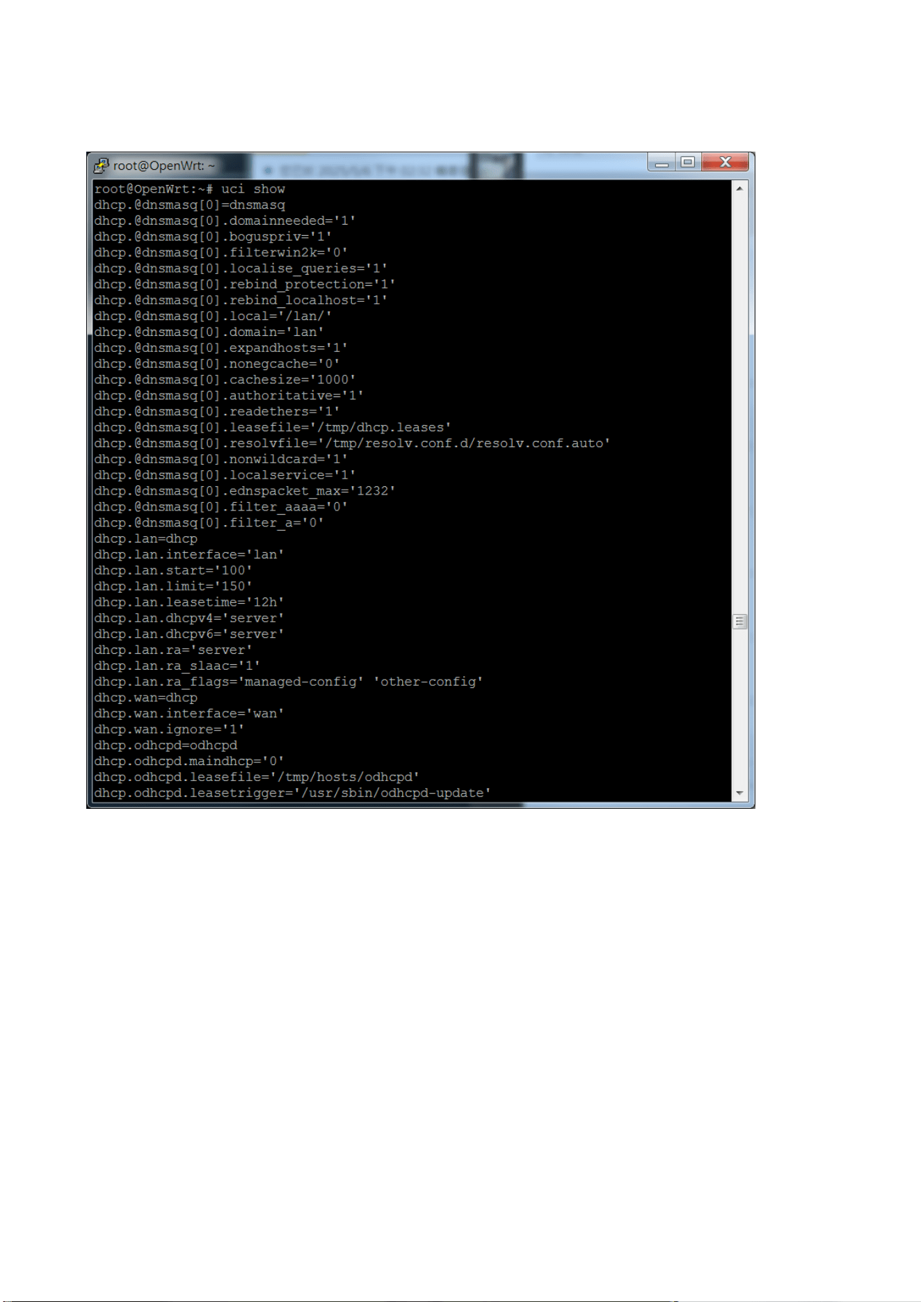
74
Read Configuration File:
root@OpenWrt:~# uci show
Scroll up/down to view all the configurations for the device.
Find the interface/configuration you want to manage, then you can use “uci set” command to modify the settings.
And you may need to restart that interface/service to activate.
Since there are lots of CLI commands, the manual can only list some of them. If the command is not listed in this
manual, you can contact our technical support, find the command through internet, such as the openwrt web site,
Chatgpt…etc.
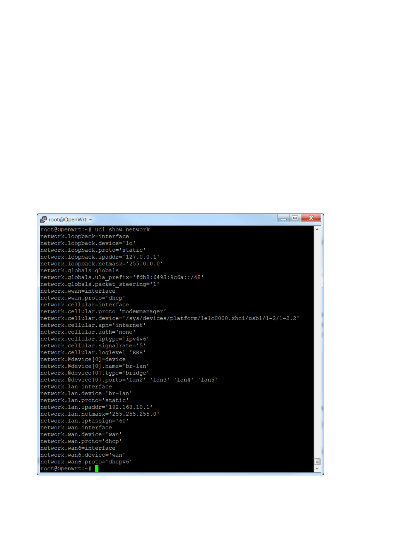
75
4.2 Major OpenWRT CLI
This chapter introduces a selected subset of commonly used OpenWrt CLI commands for basic configuration and
troubleshooting. Some commands have been customized for this product and may differ from the standard
OpenWrt implementation, syntax, or default behavior. It does not cover every available Linux/OpenWrt command.
For further details on generic OpenWrt commands, please consult the official OpenWrt website
(https://openwrt.org) or other reputable technical resources on the Internet. In case of any differences, please
follow the behavior and examples described in this manual for this device.
A set of product-specific customized CLI commands is described in the next chapter, 4.3 Customized CLI. Where
customized commands are provided for a given function, please follow the customized commands in preference to
the generic OpenWrt commands shown in this chapter.
4.2.1 CLI - Cellular
The default configuration of the Cellular interface is enabled.
Use “uci show network”, you can find the default network related settings.
◼ Parameter change:

76
Below is an example of changing cellular’s APN name and signal refresh rate. Use “uci commit network” to activate
the setting.
root@OpenWrt:~#uci set network.cellular.apn='chtapn'
root@OpenWrt:~# uci set network.cellular.signalrate='10'
root@OpenWrt:~# uci commit network
root@OpenWrt:~# uci show network.cellular
network.cellular=interface
network.cellular.proto='modemmanager'
network.cellular.device='/sys/devices/platform/1e1c0000.xhci/usb1/1-2/1-2.2'
network.cellular.apn='chtapn'
network.cellular.auth='none'
network.cellular.iptype='ipv4v6'
network.cellular.signalrate='10'
network.cellular.loglevel='ERR'
After modified the configuration, use below command to reload/restart the network
interfaces:
root@OpenWrt:~# /etc/init.d/network reload (reload the modified network interface)
root@OpenWrt:~# /etc/init.d/network restart (restart all network interfaces)
Below is another command to watch the status of the cellular module.
◼ show cellular status
root@OpenWrt:~# mmcli -m 0 (index 0, you can use Any if it is not 0)
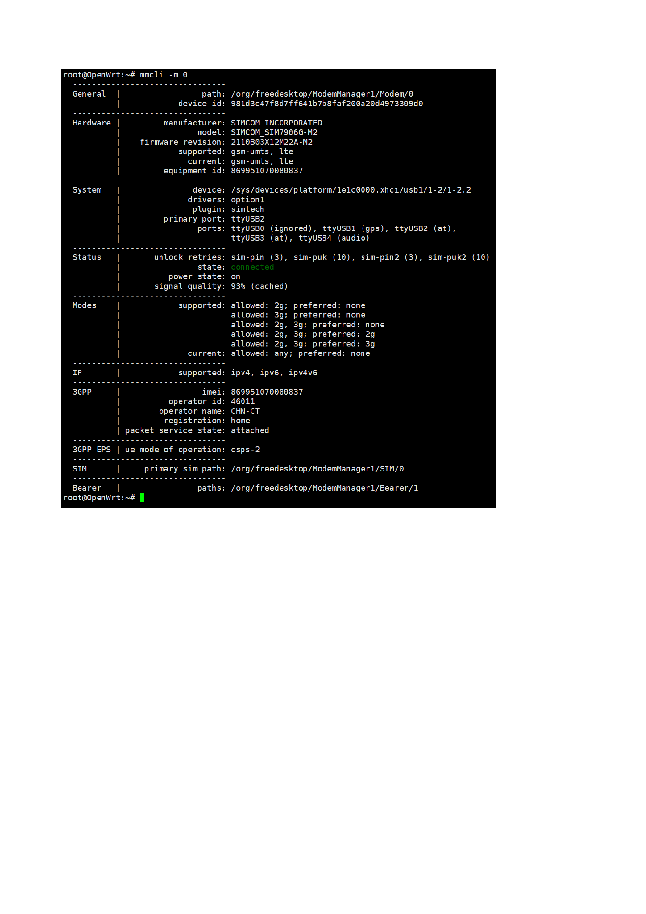
77
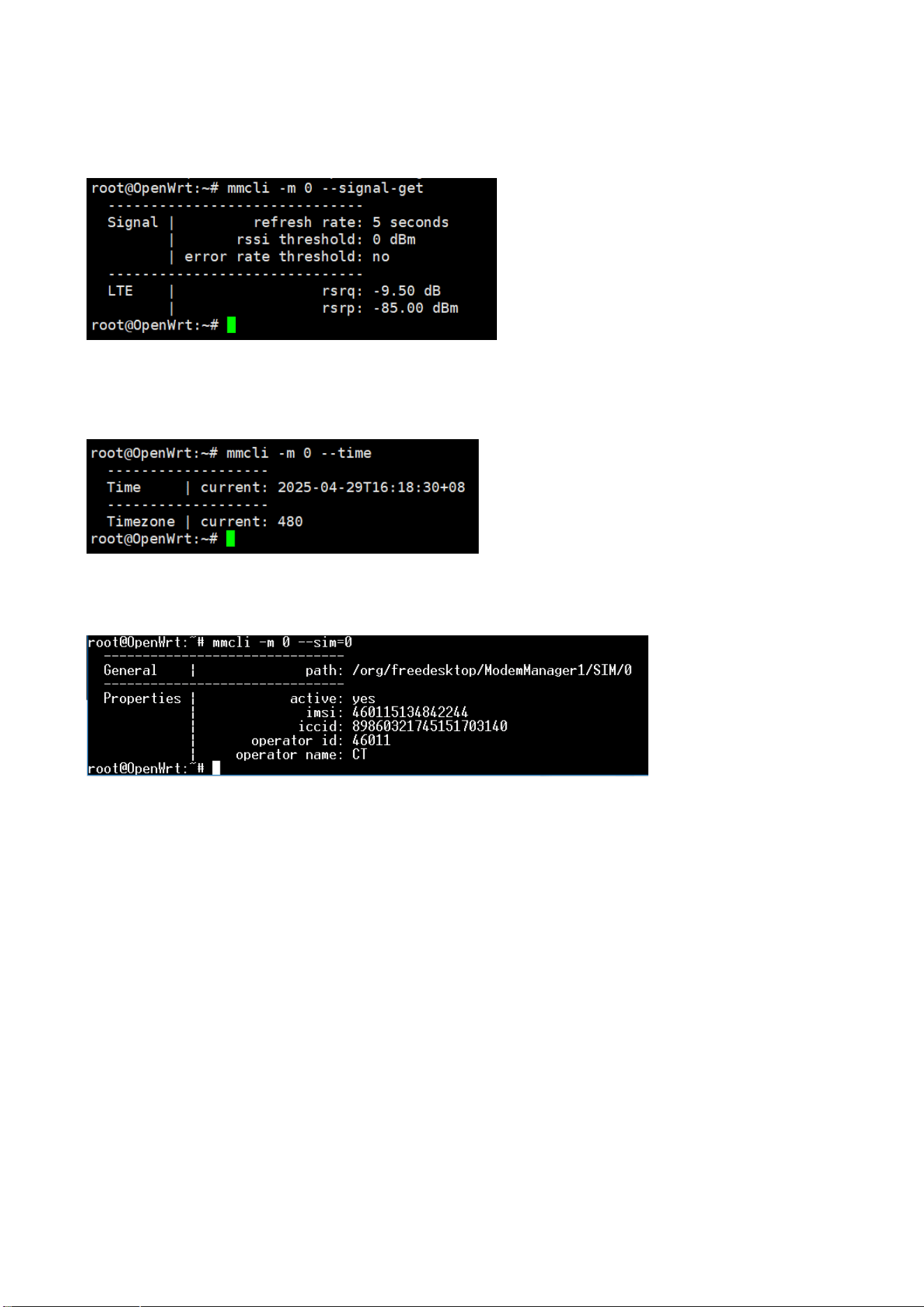
78
◼ query the signal
root@OpenWrt:~# mmcli -m 0 --signal-get
◼ 3) query the cellular time
root@OpenWrt:~# mmcli -m 0 --time
root@OpenWrt:~# mmcli -m 0 --sim=0

79
4.2.2 CLI– lan
Use “uci show network.lan”, you can find the default network lan settings.
root@OpenWrt:~# uci show network.lan
network.lan=interface
network.lan.device='br-lan'
network.lan.proto='static'
network.lan.ipaddr='192.168.10.1'
network.lan.netmask='255.255.255.0'
network.lan.ip6assign='60'
◼ Remove specific port/ports from the bri-lan interface.
Below is an example of removing the LAN port 4 and port 5 from the bridge-lan interface. This means that the port 4
and 5 are no longer used on the network.
root@OpenWrt:~# uci set network.@device[0].ports='lan2 lan3'
root@OpenWrt:~# uci commit network
root@OpenWrt:~# /etc/init.d/network reload
After changed the settings, use “uci commit network” and “/etc/init.d/network reload” to activate the new setting.
◼ Change Router’s IP address:
root@OpenWrt:/# uci set network.lan.ipaddr='192.168.10.2'
root@OpenWrt:/# uci commit network
root@OpenWrt:/# /etc/init.d/network restart
◼ Interface Shutdown
Interface shutdown command. But, this command can’t be saved in the configuration file, for temporary use.
root@OpenWrt:~# ifconfig lan3 down
◼ Default Route
Use “ip route”, you can find the default route of the lan interface.
root@OpenWrt:~# ip route
default via 10.64.64.64 dev ppp0 proto static (WAN: cellular ppp0 interface)
10.64.64.64 dev ppp0 proto kernel scope link src 10.128.173.51
192.168.10.0/24 dev br-lan proto kernel scope link src 192.168.10.1
NOTE: Currently, multiple default gateways are not supported. Therefore, if you enable multiple network segments
simultaneously and disable the original default gateway, it may cause the default route to be lost. Please restart the
default gateway interface or restart all network interfaces.
SSH command: /etc/init.d/network restart

80
4.2.3 CLI – WIFI(Wireless)
The default configuration of the Wi-Fi interface is Enabled.
The standard SSH commands described in this chapter are intended to be used in station (client) mode only.
Use “uci show”/”uci show wireless”, you can find the default settings of the wireless interface. For example:
====Default: Wi-Fi radio is Disabled====
wireless.radio0=wifi-device
wireless.radio0.type='mac80211'
wireless.radio0.path='1e140000.pcie/pci0000:00/0000:00:00.0/0000:01:00.0'
wireless.radio0.channel='auto'
wireless.radio0.band='5g'
wireless.radio0.htmode='HE20'
wireless.radio0.disabled='1'
wireless.default_radio0=wifi-iface
wireless.default_radio0.device='radio0'
wireless.default_radio0.network='wwan'
wireless.default_radio0.mode='sta'
wireless.default_radio0.ssid='Wireless'
wireless.default_radio0.encryption='none'
=====================
Enable/Disable Wi-Fi Interface
Enable/Disable Physical Radio0:
root@OpenWrt:~# uci set wireless.radio0.disabled='0' --Enable Wireless Radio0 interface
root@OpenWrt:~# uci set wireless.radio0.disabled='1' --Disable Wireless Radio0 interface
Enable/Disable logical layer (SSID)
root@OpenWrt:~# uci set wireless.default_radio0.disable=’0’ --Enable default wireless radio
root@OpenWrt:~# uci set wireless.radio0.disabled='1' --Disable default wireless radio
⚫ wireless.radio0.disabled='1' → The radio is off, so no wireless signal is broadcast.
⚫ wireless.radio0.disabled='0' and wireless.default_radio0.disable='1' → The radio is on, but SSID is disabled —
interface won’t broadcast.
⚫ wireless.radio0.disabled='0' and wireless.default_radio0.disable='0' → Both the radio and SSID are active, so
the Wi-Fi network is visible and working.
After changed the settings, use “uci commit wireless” and “wifi reload” to activate the new setings.
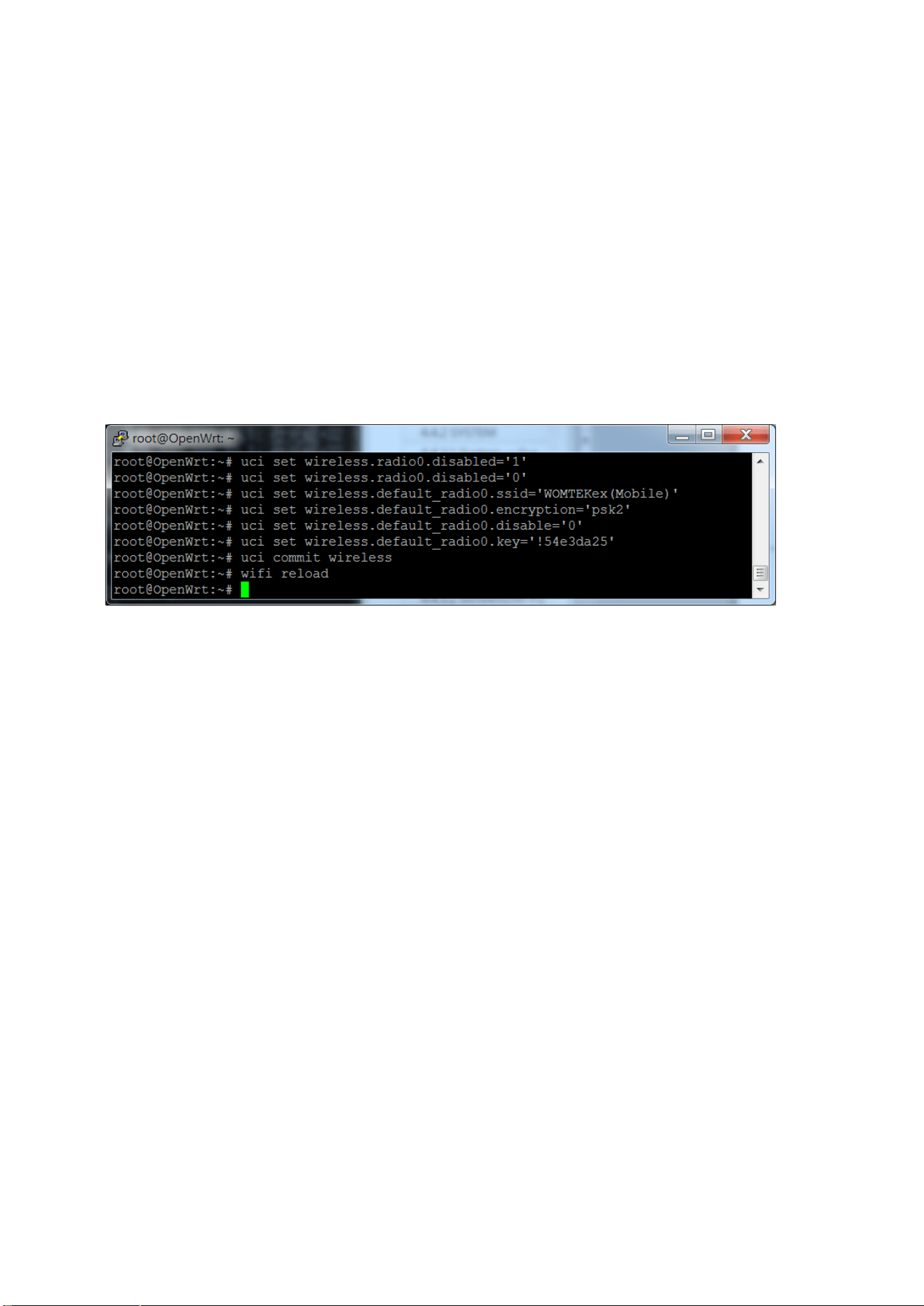
81
Change SSID Settings:
The router supports one physical radio interface and the default mode setting is client mode, you don’t need to
change the setting. You just need enter correct SSID, Encryption, Key and apply the settings.
Below is the example to use “uci set” to configure the wireless settings.
root@OpenWrt:~# uci set wireless.radio0.disabled='0'
root@OpenWrt:~# uci set wireless.default_radio0.ssid='WOMTEKex(Mobile)'
root@OpenWrt:~# uci set wireless.default_radio0.encryption=’psk2’
root@OpenWrt:~# uci set wireless.default_radio0.disable=’0’
root@OpenWrt:~# uci set wireless.default_radio0.key=’ !54e3da25’
root@OpenWrt:~# uci commit wireless
root@OpenWrt:~# wifi reload
After changed the settings, use “uci commit wireless” and “wifi reload” to activate the new setings.
Use “uci show wireless” to check the new settings:
====Enabled Wi-Fi radi0 interface and add new SSID/encryption/Key===============
wireless.radio0=wifi-device
wireless.radio0.type='mac80211'
wireless.radio0.path='1e140000.pcie/pci0000:00/0000:00:00.0/0000:01:00.0'
wireless.radio0.channel='auto'
wireless.radio0.band='5g'
wireless.radio0.htmode='HE20'
wireless.radio0.disabled='0'
wireless.default_radio0=wifi-iface
wireless.default_radio0.device='radio0'
wireless.default_radio0.network='wwan'
wireless.default_radio0.mode='sta'
wireless.default_radio0.ssid='WOMTEKex(Mobile)'
wireless.default_radio0.encryption='psk2'
wireless.default_radio0.disable='0'
wireless.default_radio0.key='!54e3da25'
=====================
Note: When Cellular and WiFi are enabled at the same time, the default route may be changed to the wwan (wifi)
interface. At this time, if you turn off the WiFi radio, the default route may be deleted. Please restart your cellular
interface or reload/restart the network interface to restore it.
SSH command: /etc/init.d/network restart
root@OpenWrt:~# /etc/init.d/network restart

82
Wi-Fi Status: iwinfo
Station mode:
root@OpenWrt:/# iwinfo
phy0-sta0 ESSID: "Wireless_5G_1E8D10"
Access Point: DE:56:7B:D6:9B:A9
Mode: Client Channel: 36 (5.180 GHz) HT Mode: HE80
Center Channel 1: 42 2: unknown
Tx-Power: 3 dBm Link Quality: 63/70
Signal: -47 dBm Noise: unknown
Bit Rate: 1200.9 MBit/s
Encryption: WPA2 PSK (CCMP)
Type: nl80211 HW Mode(s): 802.11ac/ax/b/g/n
Hardware: 14C3:7922 105B:E132 [Generic MAC80211]
TX power offset: unknown
Frequency offset: unknown
Supports VAPs: no PHY name: phy0
root@OpenWrt:~# iw dev phy0-sta0 info
Interface phy0-sta0
ifindex 159
wdev 0x2b
addr de:56:7b:d6:9b:a9
ssid Wireless_5G_1E8D10
type managed
wiphy 0
channel 36 (5180 MHz), width: 80 MHz, center1: 5210 MHz
txpower 3.00 dBm
multicast TXQ:
qsz-byt qsz-pkt flows drops marks overlmt hashcol tx-bytes tx-packets
0 0 0 0 0 0 0 0 0

83
4.3 Customized CLI & Script
This chapter describes product-specific scripts and customized CLI commands. These commands are mainly
provided for collecting device information, alarm control configuration, configuring Wi-Fi operating modes, and
handling related precautions. In particular, Wi-Fi configuration on this product follows a specific design and
command sequence; please configure Wi-Fi strictly according to the recommended procedures and examples in this
chapter to ensure correct operation and regulatory compliance.
4.3.1 Get Information Script: wr-info-get.sh
Cellular Information Retrieval Script (wr-info-get.sh)
This script is a customized script after firmware V1.8 released. The script can help you to get the information of the
router quickly.
This guide outlines how to use the command-line utility wr-info-get.sh to retrieve detailed information about your
device's cellular modem, connection, and signal quality. The output for all commands is provided in JSON format.
Execution Command
To use the script, execute it with the desired information keyword as the argument:
Script name: wr-info-get.sh
Usage syntax:
wr-info-get.sh [OPTIONS...] [-J]
⚫ Multiple options can be passed in one call; the script will output all requested fields in a single JSON object.
⚫ JSON output is enabled by default. The `-J` flag is currently accepted but does not change the output format.
Available Information Keywords (Grouped)
1. System and Hardware information ⚙
Keyword
Description
Information Retrieved
sys_all
Comprehensive system summary (various data
points).
A single query to fetch all system-related
parameters.
version
Firmware/Software Version
The current operating system or firmware version.
model
Device Model Name
The hardware model of the device.
imei
International Mobile Equipment Identity
Unique identifier for the modem hardware.
meid
Mobile Equipment Identifier
Used primarily for CDMA networks.
provider
Modem Vendor/Supplier
The manufacturer of the cellular modem.
2. Modem and SIM Status 💳
Keyword
Description
Information Retrieved
modem_state
Modem Operating Status
The current state of the modem (e.g., powered on, ready,

84
error).
sim_info
SIM Card Summary
Comprehensive information about the SIM card status.
imsi
International Mobile Subscriber
Identity
Unique identifier for the subscriber (your account).
iccid
SIM Card Serial Number
The unique serial number of the inserted SIM card.
pin
SIM Card PIN Status
Indicates if the PIN is required, verified, or disabled.
3. Network Registration and APN Settings 📡
Keyword
Description
Information Retrieved
connection_info
Connection Status
Summary
A combined view of network registration and data
service status.
operator_name
Mobile Network Operator
Name
The name of the currently connected carrier (e.g.,
AT&T, O2).
operator_state
Network Registration
Status
Indicates if the device is registered to the network
(e.g., registered, searching).
0: not registered
1: registered, home network
2: not registered, but MT is trying to attach or
searching an operator to register to
3: registration denied
4: unknown (ex: out of E-UTRAN coverage)
5: registered, roaming
(not list, please check with our support engineer.)
data_service_state
Data Service Status
Indicates if the data connection is active (e.g.,
connected, disconnected).
operator_id
Operator ID
The numerical identifier for the network (e.g., MCC +
MNC).
mcc / mnc
Mobile Country/Network
Code
Codes identifying the country and the specific
operator.
apn
Access Point Name
The name of the configured data access point.
auth
APN Authentication Type
The authentication protocol used for the APN (e.g.,
PAP, CHAP).
cell_user / cell_password
APN Credentials
Username and password for APN authentication (if
required).
interface_addr /
interface_addr_ipv6
Interface IP Address
The device's assigned IPv4 and IPv6 addresses on the
cellular interface.
conn_date
Connection Timestamp
The time and date when the current connection was
established.

85
4. Signal Strength and Quality Metrics 📶
These metrics are crucial for evaluating cellular performance.
Keyword
Description
Typical Use
rssi /
scc_rssi
Received Signal Strength Indicator
(Primary/Secondary Carrier)
General measurement of signal power. Higher
(closer to 0) is better.
rsrp /
scc_rsrp
Reference Signal Received Power
(Primary/Secondary Carrier)
A more accurate measure of the power from the
serving cell tower. Higher (closer to 0) is better.
rsrq /
scc_rsrq
Reference Signal Received Quality
(Primary/Secondary Carrier)
Measures the quality of the signal, considering
noise and interference. Higher (closer to 0) is
better.
sinr
Signal-to-Interference-plus-Noise Ratio
Measures the useful signal power relative to
interference. Positive values are good.
rscp
Received Signal Code Power
Used for 3G (WCDMA) networks.
band_info
Detailed Cell/Band Information
Includes Cell ID, Band, EARFCN, DL/UL Bandwidth,
and Carrier Aggregation (SCC) details.
5. Connection Details and Data Usage 📊
Keyword
Description
Information Retrieved
band_info
Detailed Cell/Band
Information
Detailed metrics including Cell ID, Band, EARFCN
(Frequency Channel), DL/UL Bandwidth, and Carrier
Aggregation (SCC) details.
data_transmission_info
Data Transmission
Summary
Combined summary of band, bandwidth, signal
metrics, and data usage.
interface_addr /
interface_addr_ipv6
Interface IP Address
The device's assigned IPv4 and IPv6 addresses on the
cellular interface.
conn_date
Connection Timestamp
The time and date when the current connection was
established.
cell_rx_bytes / cell_tx_bytes
Data Traffic
(Received/Transmitted)
The total number of bytes downloaded (rx) and
uploaded (tx) since the last modem restart or reset.
cell_rx_tx_bytes
Total Data Traffic
A combined output of both received and transmitted
bytes.
6. Wi-Fi Client Connection Information (STA)
These commands are used when the device operates as a client (Station) connecting to an upstream Wi-Fi network.
Keyword
Description
Information Retrieved (Equivalent to)

86
sta_info
Summary STA Connection
Status
sta_state (Connection Status), ESSID, and Channel.
Aggregates STA state, association, signal and data rates into a single
JSON object.
sta_state
Detailed STA Connection Info
Returns the STA mode state, enabled or disabled.
sta_assoc
Returns association status and BSSID/SSID info.
sta_signal
Returns the Wi-Fi RSSI/Signal level for the STA link.
sta_rx_rate
Returns the current RX data rate of the STA link.
sta_tx_rate
Returns the current TX data rate of the STA link.
sta_addr
Returns the MAC address of the STA interface.
> Note: `sta_tx_power` is implemented internally but its CLI option is commented out in this version.
7. Multi-WAN path selection
⚫ `network_used` – Returns which uplink path is currently used by the system (e.g. wired WAN vs. cellular vs.
Wi-Fi), based on routing and interface checks.
8. Alarm State and Status
These commands are used to monitor the alarm state and status.
Keyword
Description
Information Retrieved (Equivalent to)
alarm_state
Alarm state enabled or not
enabled
Return: "alarm_state":0
alarm_status
Monitor the status of Ping alarm,
high temperature alarm, Cellular
and Wi-Fi module’s hardware
ready or not
You can see the specific alarm is activated or not.
There are five different return types:
"alarm_state":0, =>alarm state
"alarm_ping":0, =>Ping alarm/watchdog
"alarm_temperature":0, =>High Temperature alarm
"alarm_hw_cellular":0, =>Cellular module hardware status
"alarm_hw_wireless":0 =>Wi-Fi module hardware status
9. Formatting / flags
* `-J` – Reserved flag for JSON output. In this version it is accepted but does not modify behavior (JSON output is
always enabled).

87
4.3.2 Wireless Operation Mode Script: wr-wireless-mode.sh
Wireless Operating Modes User Manual
Your device's Wi-Fi module is primarily designed to function as a client (Station), allowing it to connect to an external
network. You can control the mode using the dedicated command line utility: wr-wireless-mode.sh.
Station (STA) Mode (Primary Client Mode)
Purpose: The default and most stable mode for accessing an external network.
Feature
Description
Role
Your device acts as a standard Wi-Fi client.
Connectivity
Connects to an external Wi-Fi router or access point (the upstream network).
Status
Active only when authenticated and connected.
Command: wr-wireless-mode.sh sta
Expected Output: return: success
Dynamic Frequency Selection (DFS)
What are DFS Bands?
DFS (Dynamic Frequency Selection) bands are a set of 5 GHz channels shared with high-priority radar systems. Wi-Fi
equipment operating on these channels must constantly listen for radar and, if detected, immediately cease
transmission and switch channels.
DFS Regulatory Declaration:
"DFS (Dynamic Frequency Selection) channel capability is enabled by default in STA (Client) mode, requiring no
additional user configuration or commands. When operating as a client, the device automatically complies with the
upstream AP's channel decisions and follows its operation within the DFS band. All hardware and firmware
restrictions regarding DFS parameters are strictly defined in accordance with regulatory requirements and are
completely locked from user modification."

88
4.3.3 Alarm-Ctl Function
The alarm-ctl function monitors various hardware and network conditions and drives a GPIO output when an alarm
is triggered. Each alarm type is configured as a separate alarm-ctl section in UCI and uses a common GPIO pin
(default: gpio491) as the alarm output.
This chapter describes the following alarm types:
⚫ Network Condition: Ping alarm (network reachability)
⚫ Hardware Condition: Temperature alarm (LTE module temperature), Wireless module alarm (Wi-Fi hardware
errors), LTE module alarm (cellular module presence)
Uci show to list all the alarm-ctl setting as below:
root@OpenWrt:/# uci show alarm-ctl
alarm-ctl.@alarm-ctl[0]=alarm-ctl
alarm-ctl.@alarm-ctl[0].gpio='gpio491'
alarm-ctl.@alarm-ctl[0].mode='none'
alarm-ctl.@alarm-ctl[0].target_ip='8.8.8.8'
alarm-ctl.@alarm-ctl[0].count='1'
alarm-ctl.@alarm-ctl[0].timeout='1'
alarm-ctl.@alarm-ctl[0].defer_time='15'
alarm-ctl.@alarm-ctl[0].interval='10'
alarm-ctl.@alarm-ctl[0].fail_limit='3'
alarm-ctl.@alarm-ctl[1]=alarm-ctl
alarm-ctl.@alarm-ctl[1].gpio='gpio491'
alarm-ctl.@alarm-ctl[1].mode='temperature'
alarm-ctl.@alarm-ctl[1].high='80'
alarm-ctl.@alarm-ctl[1].low='-30'
alarm-ctl.@alarm-ctl[1].interval='15'
alarm-ctl.@alarm-ctl[2]=alarm-ctl
alarm-ctl.@alarm-ctl[2].gpio='gpio491'
alarm-ctl.@alarm-ctl[2].mode='hw-wireless'
alarm-ctl.@alarm-ctl[2].interval='10'
alarm-ctl.@alarm-ctl[3]=alarm-ctl
alarm-ctl.@alarm-ctl[3].gpio='gpio491'
alarm-ctl.@alarm-ctl[3].mode='hw-cellular'
alarm-ctl.@alarm-ctl[3].interval='10'
4.3.3.1 Network Ping Alarm
The Ping Alarm function periodically sends ICMP echo requests (ping) to a target IP address. When consecutive ping
failures reach the configured limit, the alarm state is triggered and the corresponding GPIO output can be used as an
alarm signal.
i. gpio: Specifies the GPIO pin used for the alarm output. Default: gpio491 (No need to change this!!)

89
ii. mode: Controls whether the ping alarm function is enabled.
"ping" – enable ping alarm function
"none" – disable ping alarm function
iii. target_ip: Specifies the target IP address to be pinged (e.g. gateway, server, or DNS).
iv. count: Number of ping packets sent in each check cycle.
v. timeout: Ping timeout for each packet, in seconds.
vi. defer_time: Initial delay before the first ping check is started, in seconds.
vii. interval: Interval between ping check cycles, in seconds.
viii. fail_limit: Number of consecutive failed ping check cycles required to trigger the alarm.
Configuration Examples
(1) Enable Ping Alarm
The following example enables the ping alarm and pings 8.8.8.8 periodically:
uci set alarm-ctl.@alarm-ctl[0].mode='ping'
uci set alarm-ctl.@alarm-ctl[0].target_ip='8.8.8.8'
uci set alarm-ctl.@alarm-ctl[0].count='1'
uci set alarm-ctl.@alarm-ctl[0].timeout='1'
uci set alarm-ctl.@alarm-ctl[0].defer_time='15'
uci set alarm-ctl.@alarm-ctl[0].interval='10'
uci set alarm-ctl.@alarm-ctl[0].fail_limit='3'
uci commit alarm-ctl
/etc/init.d/alarm-ctl restart
In this example:
The first ping check starts after 15 seconds (defer_time='15'). Then the device sends 1 ping every 10 seconds
(count='1', interval='10'). If 3 consecutive cycles fail (fail_limit='3'), the alarm is triggered.
(2) Disable Ping Alarm
uci set alarm-ctl.@alarm-ctl[0].mode='none'
uci commit alarm-ctl
/etc/init.d/alarm-ctl restart

90
4.3.3.2 Hardware Condition Alarm
There are three different types Hardware Condition alarms: Temperature alarm (LTE module temperature), Wireless
module alarm (Wi-Fi hardware errors), LTE module alarm (cellular module presence)
1. Temperature Alarm (LTE Module Temperature)
The temperature alarm monitors the temperature reported by the LTE module. If the measured temperature is
higher than the configured high limit or lower than the configured low limit, the alarm is triggered and the GPIO
output will indicate an alarm condition.
1)Parameters
gpio: Specifies the GPIO pin used for the alarm output. Default: gpio491
mode
Controls whether the temperature alarm is enabled.
"temperature" – enable temperature alarm
"none" – disable this alarm
High: High temperature threshold in degrees Celsius (integer).
Low: Low temperature threshold in degrees Celsius (integer).
Interval: Measurement interval in seconds.
2) Default configuration
Status: Enabled
gpio: gpio491
high: 80 °C
low: -30 °C
interval: 15 seconds
3) Configuration examples
Enable temperature alarm
uci set alarm-ctl.@alarm-ctl[1].mode='temperature'
uci set alarm-ctl.@alarm-ctl[1].high='10'
uci set alarm-ctl.@alarm-ctl[1].low='-10'
uci set alarm-ctl.@alarm-ctl[1].interval='15'
uci commit alarm-ctl
/etc/init.d/alarm-ctl restart
Disable temperature alarm
uci set alarm-ctl.@alarm-ctl[1].mode='none'
uci commit alarm-ctl
/etc/init.d/alarm-ctl restart

91
2. Wireless Module Alarm (Wi-Fi Hardware Errors)
The wireless module alarm checks for hardware-related errors during system boot and periodically scans the kernel
log (dmesg) for Wi-Fi error messages.
1) Parameters
gpio: Specifies the GPIO pin used for the alarm output. Default: gpio491
mode: Controls whether the wireless-module alarm is enabled.
"hw-wireless" – enable wireless hardware alarm
"none" – disable this alarm
Interval: Polling interval in seconds for checking the kernel log.
2) Default configuration
Status: Enabled
gpio: gpio491
interval: 10 seconds
3) Configuration examples
Enable wireless module alarm
uci set alarm-ctl.@alarm-ctl[2].mode='hw-wireless'
uci set alarm-ctl.@alarm-ctl[2].interval='15'
uci commit alarm-ctl
/etc/init.d/alarm-ctl restart
Disable wireless module alarm
uci set alarm-ctl.@alarm-ctl[2].mode='none'
uci commit alarm-ctl
/etc/init.d/alarm-ctl restart

92
3. LTE Module Alarm (Cellular Presence/Health)
The LTE module alarm periodically checks the LTE/cellular module hardware health.
1) Parameters
Gpio: Specifies the GPIO pin used for the alarm output. Default: gpio491
Mode: Controls whether the LTE-module alarm is enabled.
"hw-cellular" – enable LTE hardware alarm
"none" – disable this alarm
Interval: Polling interval in seconds for checking the LTE module status.
2) Default configuration
Status: Enabled
gpio: gpio491
interval: 10 seconds
3) Configuration examples
Enable LTE module alarm
uci set alarm-ctl.@alarm-ctl[3].mode='hw-cellular'
uci set alarm-ctl.@alarm-ctl[3].interval='15'
uci commit alarm-ctl
/etc/init.d/alarm-ctl restart
Disable LTE module alarm
uci set alarm-ctl.@alarm-ctl[3].mode='none'
uci commit alarm-ctl
/etc/init.d/alarm-ctl restart
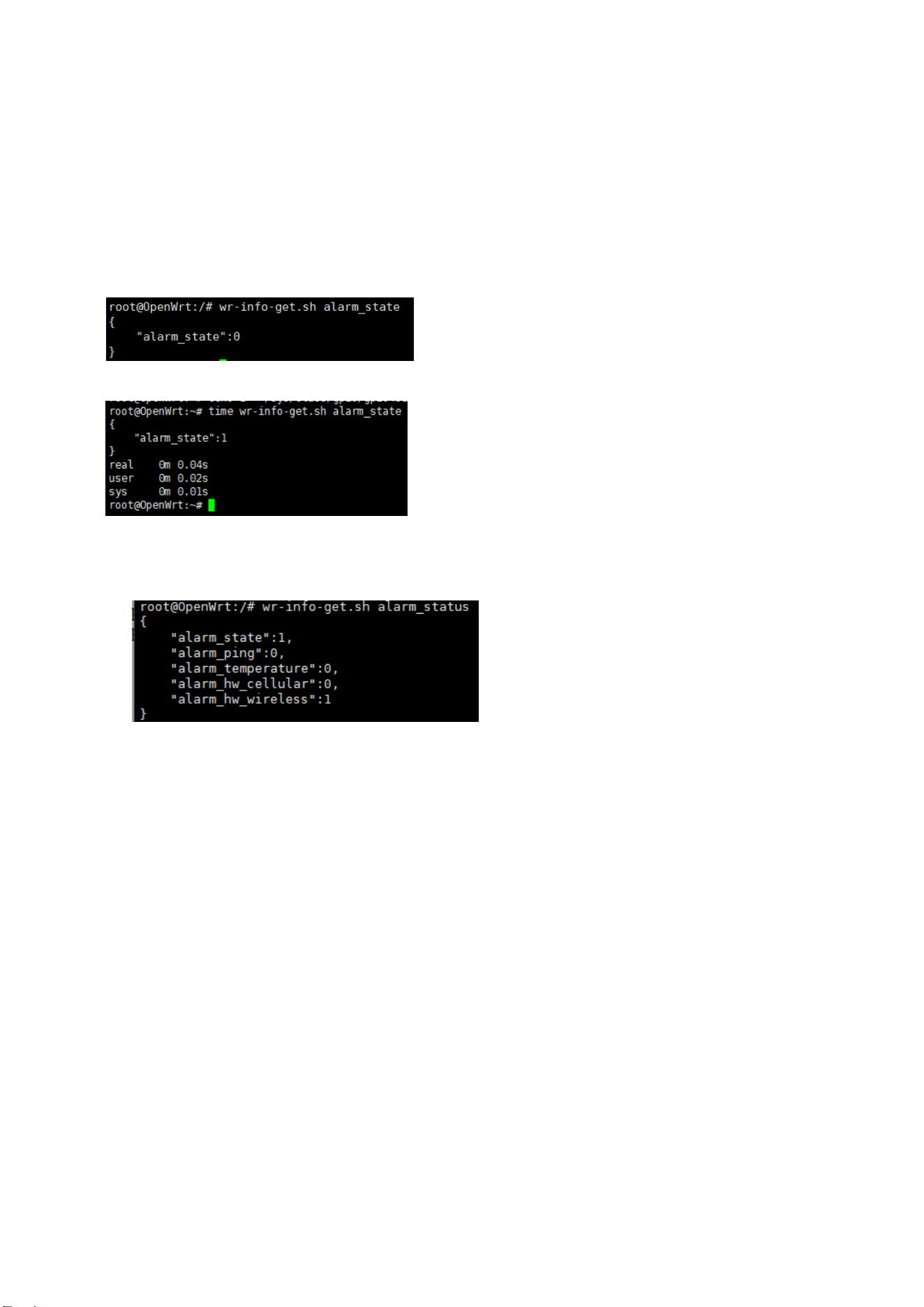
93
4.3.3.3 Reading Alarm Status
Get Alarm State
You can query the current alarm state using the following command:
Command: wr-info-get.sh alarm_state
Return values:
0 – alarm is not triggered
1 – alarm is triggered
Get Alarm Status
Command: wr-info-get.sh alarm_status
Ex:
It shows the Wireless Module Alarm is trigged.
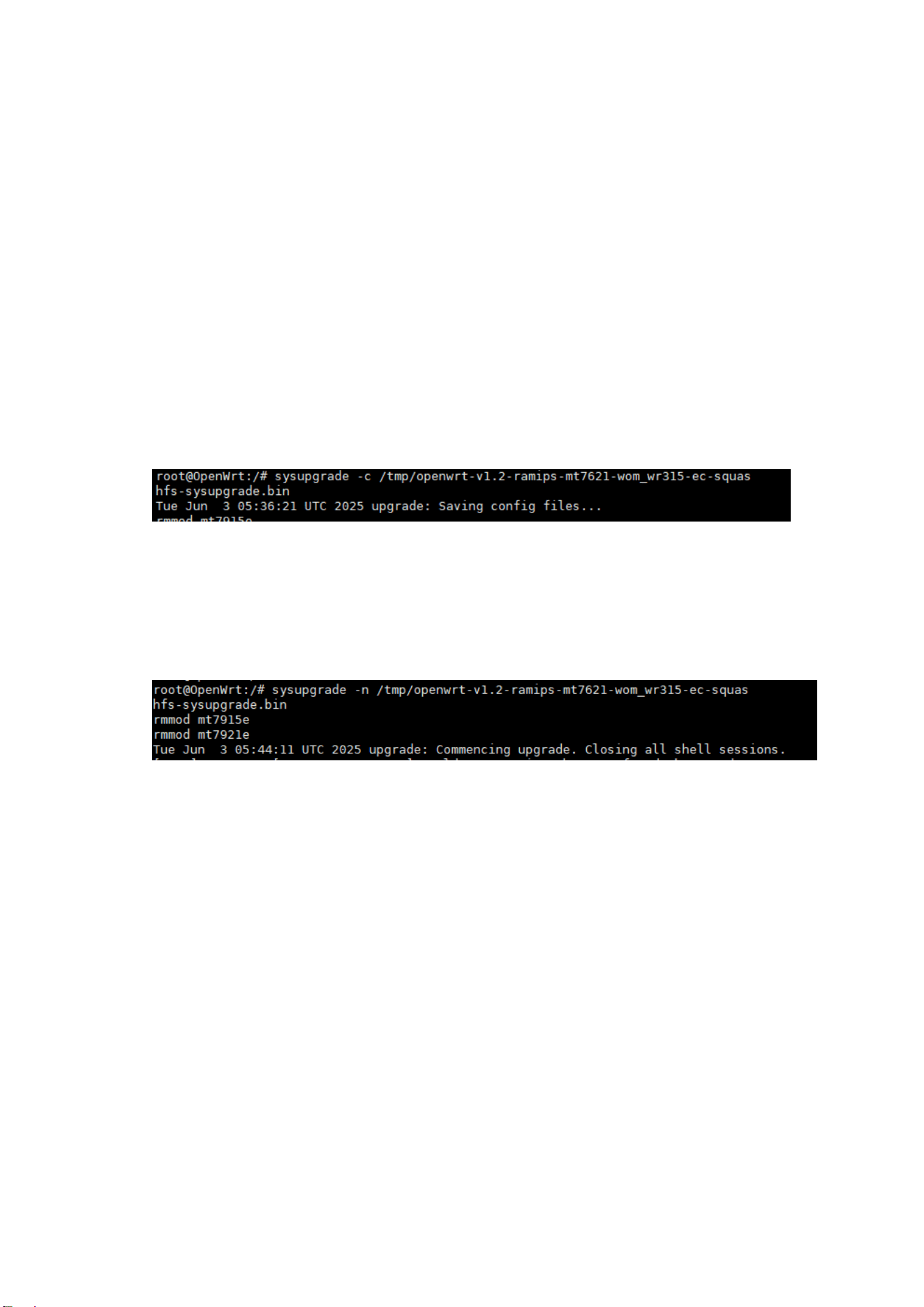
94
4.4 Firmware upgrade
- User can use SCP to upload firmware file to directory /tmp
cd /tmp
wget http://your-server.com/firmware/openwrt-v1.9-ramips-mt7621-wom_wr315-ec-squashfs-sysupgrade.bin
or
scp /folder/openwrt-v1.9-ramips-mt7621-wom_wr315-ec-squashfs-sysupgrade.bin [email protected]:/tmp/
([email protected] = Login username is root, Router IP is 192.168.10.1)
- Firmware upgrade and keep configuration
command: sysupgrade -c firmware_name
example: upgrade /tmp/openwrt-v1.2-ramips-mt7621-wom_wr315-ec-squashfs-sysupgrade.bin and keep
configuration
- Firmware upgrade and reload default
command: sysupgrade -n firmware_name
example: upgrade /tmp/openwrt-v1.2-ramips-mt7621-wom_wr315-ec-squashfs-sysupgrade.bin and reload
default
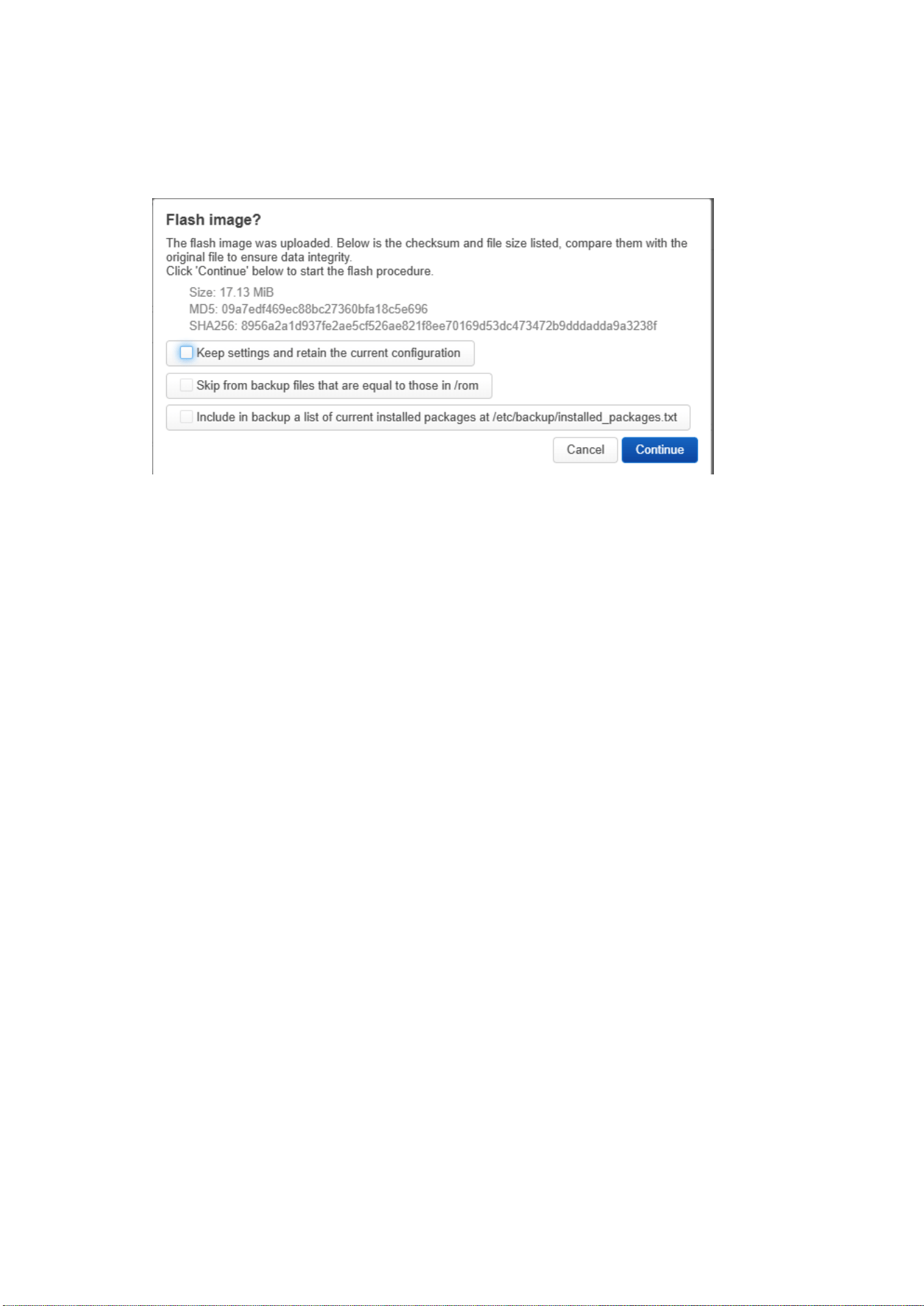
95
- Firmware Upgrade Options Explained (LuCI vs. CLI sysupgrade)
Below is the screenshot of the firmware upgrading when using LuCI Web GUI. The LuCI options correspond
directly to the parameters used in the CLI command ‘sysupgrade’.
Firmware Upgrade While Keeping Configuration
(This corresponds to the **checked** “Keep settings and retain the current configuration” option shown in the
screenshot.)
CLI Equivalent
1. `sysupgrade -c`
The `-c` parameter keeps the current configuration and skips all files that are identical to those in `/rom`.
This mode provides the most complete preservation of user settings while avoiding unnecessary backup files.
This is equivalent to:
✔Keep settings and retain the current configuration
✔Skip from backup files that are equal to those in /rom
2. `sysupgrade` (no parameters)
Without `-c`, sysupgrade uses the default backup behavior. (The system backs up: `/etc/` and files listed in
`/lib/upgrade/keep.d/`)
This is equivalent to:
✔Keep settings and retain the current configuration
✘Skip from backup files that are equal to those in /rom (not selected)
Firmware Upgrade and Reset to Factory Defaults
(This corresponds to NOT checking “Keep settings and retain the current configuration”.)
CLI Equivalent
`sysupgrade -n`
The `-n` parameter discards all current settings.
No configuration is backed up or restored after flashing.
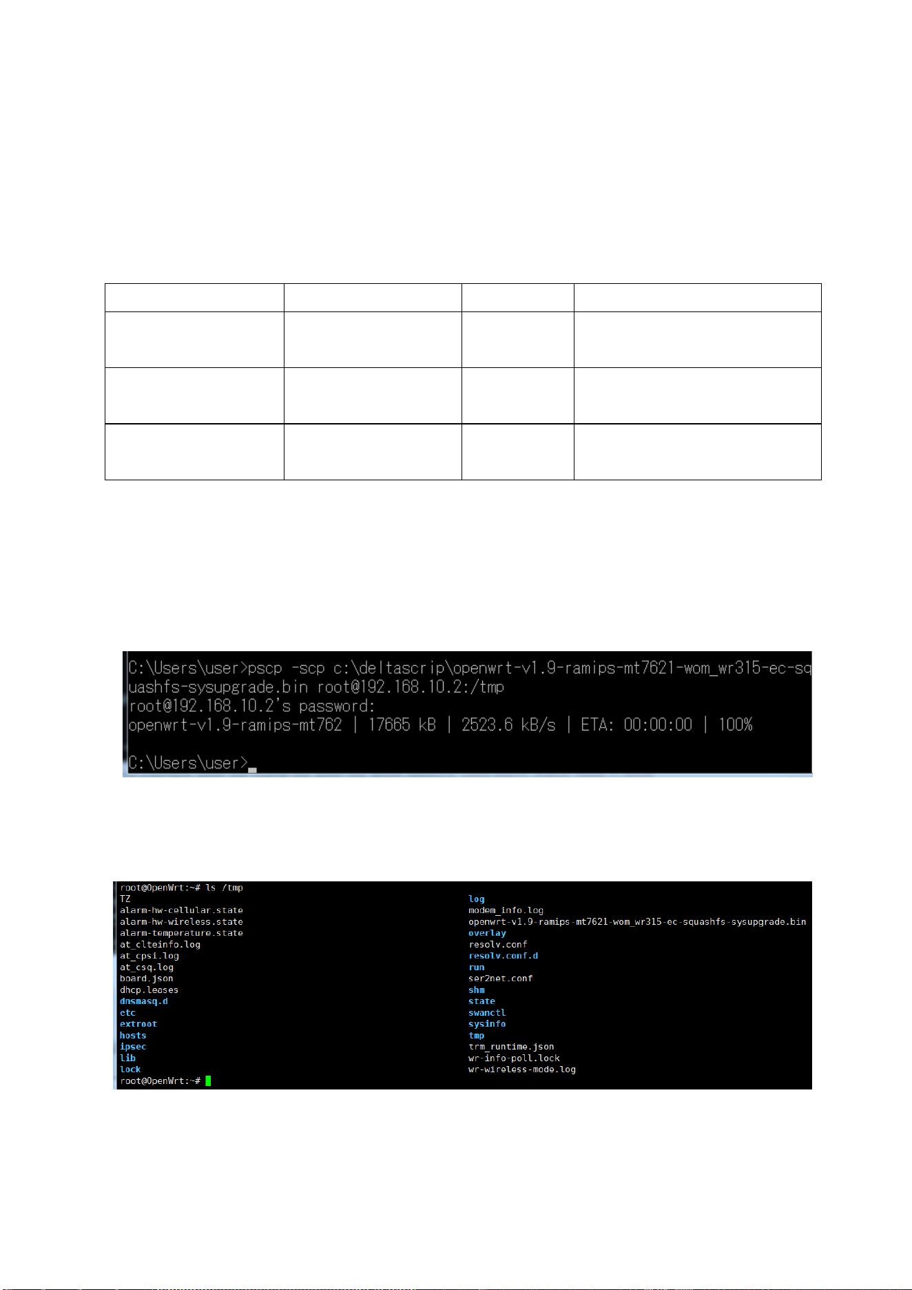
96
The device boots with factory-default configuration.
This equals leaving all options unchecked:
✘Keep settings and retain the current configuration
✘Skip from backup files equal to /rom
✘Include list of current installed packages
Summary Table:
Mode
LuCI Opton
CLI Equivalent
Behavior
Upgrade +
Keep Config (Full)
✔Keep settings,
✔Keep identical
Sysupgrade -c
Keep config; skip files identical to
/rom
Upgrade +
Keep Config (Default)
✔Keep settings,
✘Skip identical
Sysupgrade
Keep config using default backup
rules
Upgrade +
Reset to Default
✘Keep settings
Sysupgrade –n
Do not keep any configuration
- Below is the example of upgrading firmware V1.9 to the router through the WinXP computer.
C:\Users\user>pscp -scp c:\deltascrip\openwrt-v1.9-ramips-mt7621-wom_wr315-ec-squashfs-sysupgrade.bin
[email protected].2:/tmp
‘=>upload file to router 192.168.10.2, username is root; (enter the password during the pop-up prompt window)
openwrt-v1.9-ramips-mt762 | 17665 kB | 2208.1 kB/s | ETA: 00:00:00 | 100% ‘=>wait until 100% done
root@OpenWrt:~# ls /tmp ‘=>Check whether the file is uploaded or not. Not must.
root@OpenWrt:~# sysupgrade /tmp/openwrt-v1.9-ramips-mt7621-wom_wr315-ec-squashfs-sysupgrade.bin
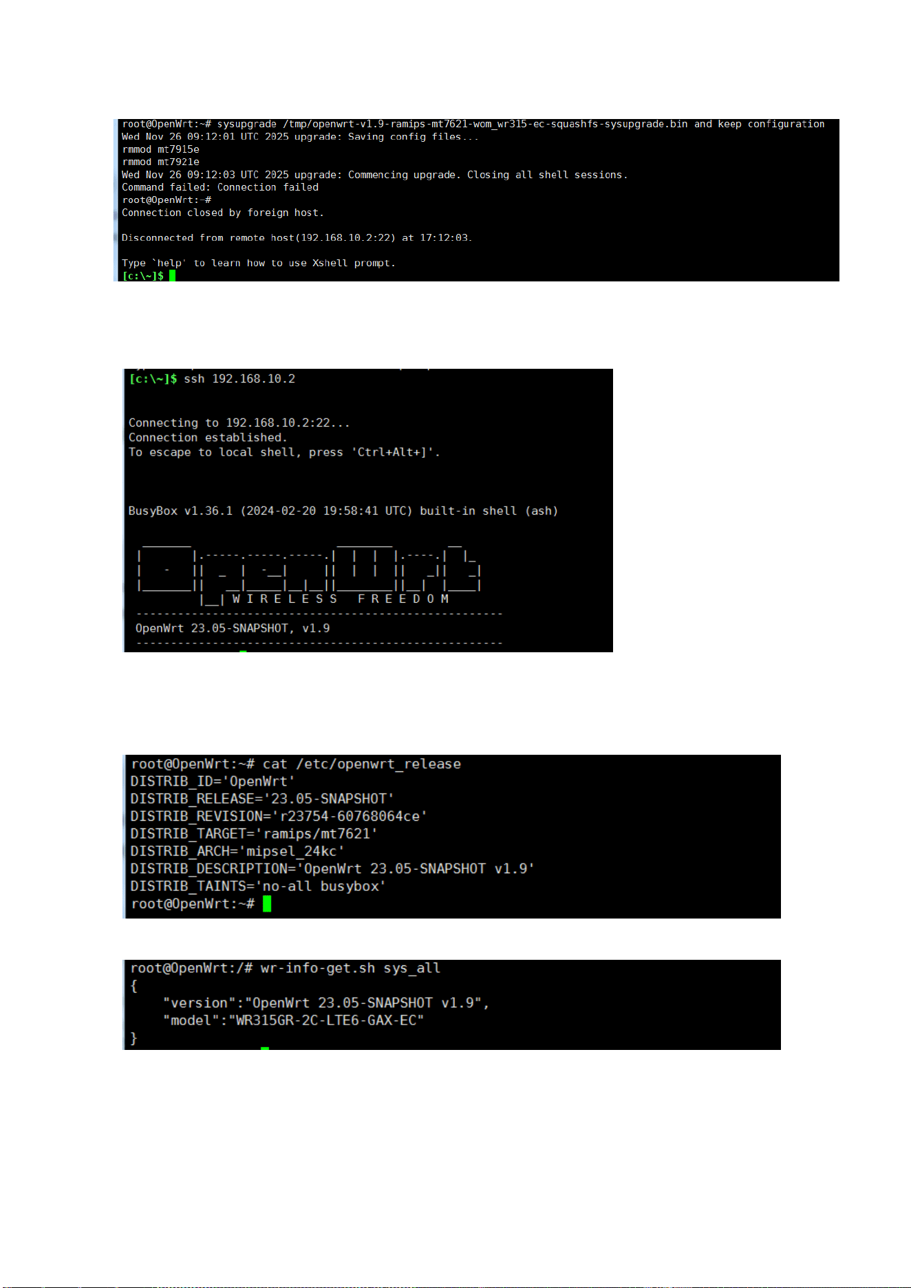
97
and keep configuration ‘=>System upgrade and keep the configuration.
[c:\~]$ ssh 192.168.10.2 ‘=>Reconnect the router’s SSH interface
-----------------------------------------------------
OpenWrt 23.05-SNAPSHOT, v1.9 ‘=>You can see the firmware version is updated.
-----------------------------------------------------
root@OpenWrt:~# cat /etc/openwrt_release ‘=>Check Firmware version
root@OpenWrt:/# wr-info-get.sh sys_all ‘=>Check System info by WOM script
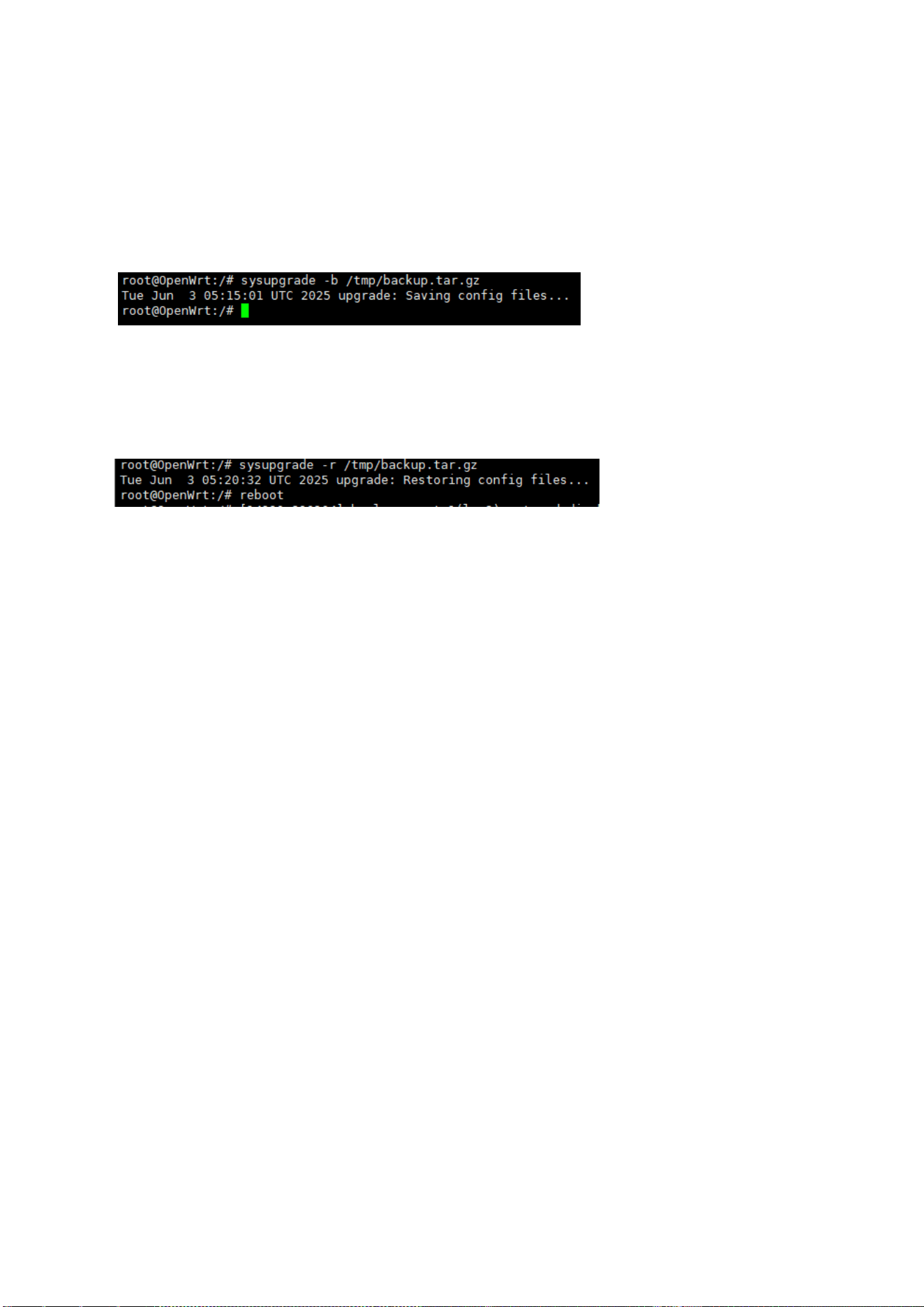
98
4.5 Configuration backup/restore
- Uer can use SCP to upload/download configuration file to/from directory /tmp
- Backup
command: sysupgrade -b file_name
example: backup configuration to /tmp/backup.tar.gz
- Restore
command: sysupgrade -r file_name
Note: You need to reboot the router to activate the settings of the uploaded config file!
example: restore /tmp/backup.tar.gz and reboot
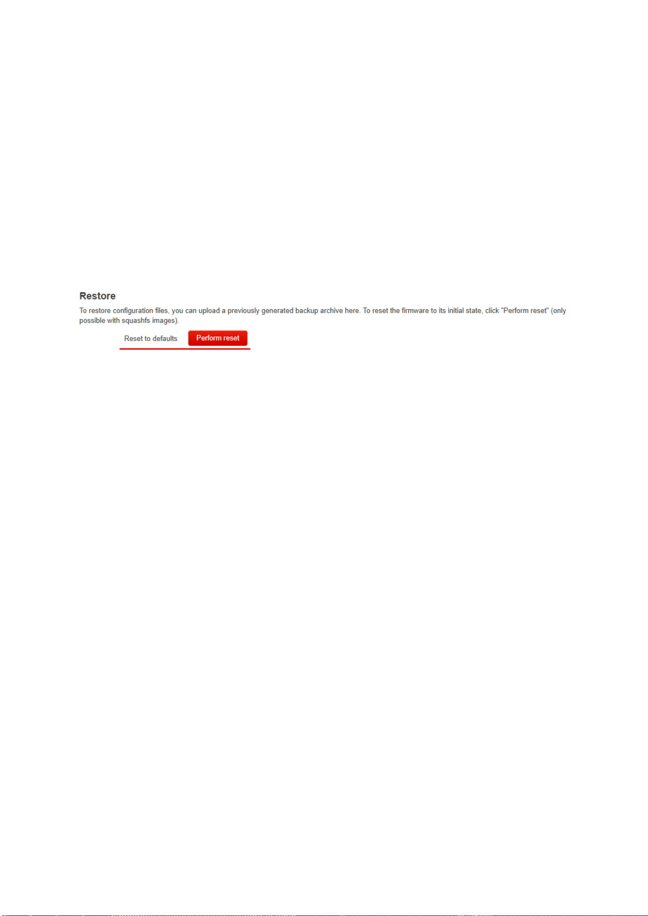
99
4.6 Reset to Default
User can use ‘jffs2reset’ to progress the reset default, this command is the same as you user “Reset” button
to active reload default.
root@OpenWrt:~# jffs2reset
This will erase all settings and remove any installed packages. Are you sure? [N/y]
y
/dev/mtdblock6 is mounted as /overlay, only erasing files
root@OpenWrt:~# reboot
Compare to the Web GUI:

100
5. REVISION HISTORY
Version
Description
Date
Editor
Draft 1
1
st
draft version, modify from WR3x2GR UM, update the Hardware
description of the WR315GR-2C.
2022/11/22
Orwell
Draft 2
2
nd
draft version, update SW functions and web GUI.
2022/11/23
Orwell
Draft 3
Modify Antenna to Optional Antenna, update SMA mapping
Remove SD features & description
2022/12/14
Orwell
Draft 4
Update web configuration function based on firmware v1.3
2022/12/16
Jerry.Lian
V1.0
Change draft 5 to V1.0
Add WR315G-LTEx2
2023/09/06
Jerry.Lian
/Orwell
V1.1
Update LED Indication of WR315GR-LTEx2
Add more description of the Dual SIM dual Active mode
2024/09/07
Orwell
V1.2
Add WR315G-2C-LTE6-GAX model
Add EC OS in the manual
2024/4/30
Orwell
V1.2a
Add SSH command of the OpenWrt EC OS
2024/5/5
Orwell
V1.3
For WR315G-2C-LTE6-GAX-EC model only.
Add customized script to get info, wireless operation configuration and
alarm configuration.
Add Firmware upgrade, confirmation backup, reset to default CLI.
2025/12/01
Orwell
V1.3 draft 6
Add Declaration of comformity, Safety Precausion
2026/1/8
Orwell
V1.3b/c/d/e
Correct wording
Update optional antenna’s gain table
2026/7/30
Orwell