MANUAL 10301A-SB REV 1 (09-22)
$21.00
Gas Fired Steamer
MANUAL SECTION CO
IMPORTANT FOR FUTURE REFERENCE
Please complete this information and retain this
manual for the life of the equipment:
Model #:
___________________________
Serial #:
___________________________
Date Purchased:
_____________________
WARNING
Improper installation, adjustment, alteration, service or maintenance can cause property damage, injury
or death. Read the installation, operating and maintenance instructions thoroughly before installing or
servicing this equipment.
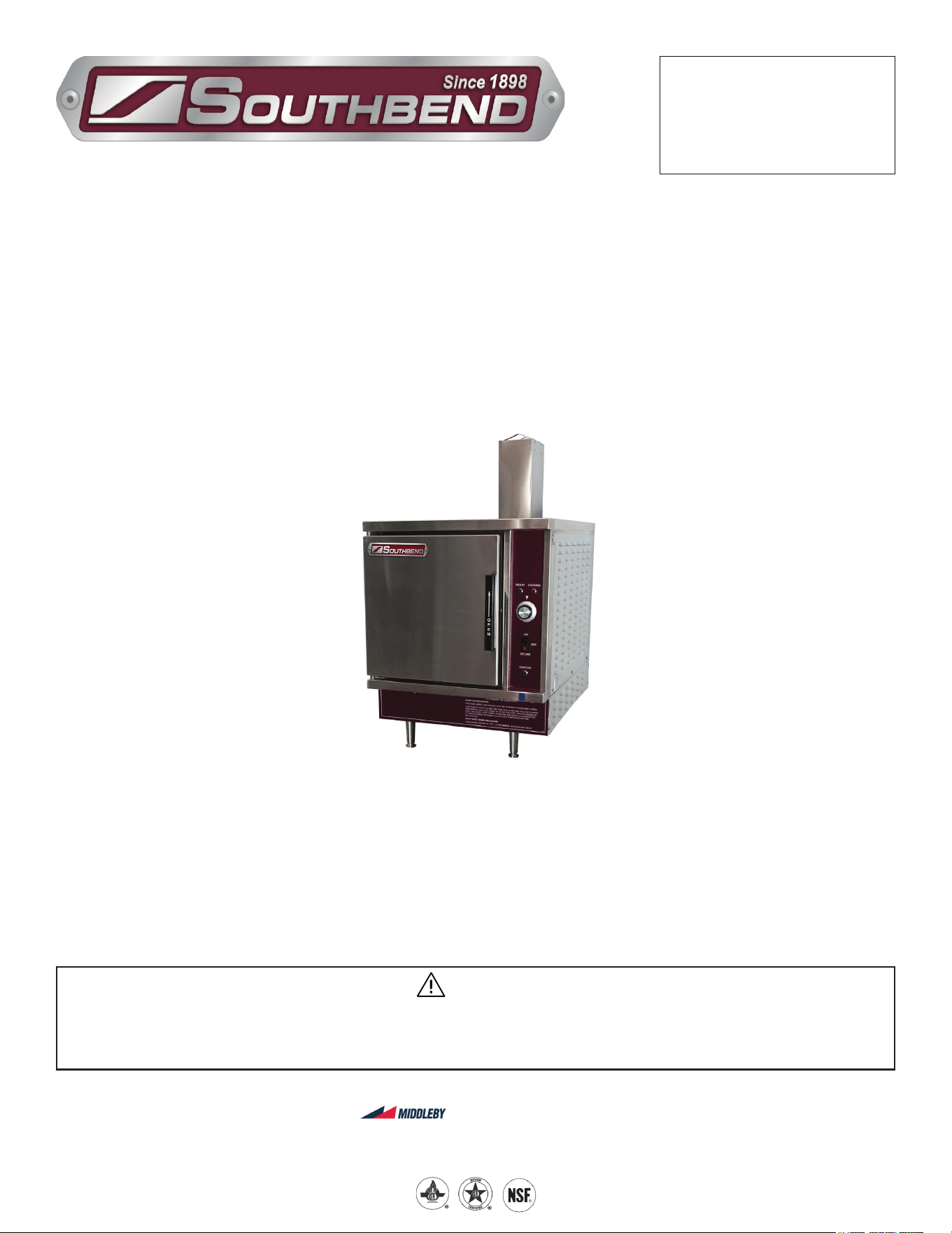
Model SX-6G3-SB
GAS FIRED STEAMER
SX-6G3-SB
Installation & Operation Manual
SOUTHBEND STEAM
A Middleby Company
1100 Old Honeycutt Road Fuquay-Varina, North Carolina 27526 USA
www.southbendnc.com
INSTALLATION & OPERATION MANUAL 10301A-SB REV 1 (09-22)
PAGE
2
OF 16
Gas Fired Steamer
SAFETY PRECAUTIONS
Before installing and operating this equipment, be sure everyone involved in its operation is fully trained and aware of
precautions. Accidents and problems can be caused by failure to follow fundamental rules and precautions.
The following symbols, found throughout this manual, alert you to potentially dangerous conditions to the operator,
service personnel, or to the equipment.
CAUTION
WARNING
NOTICE
This symbol warns of immediate hazards that will result in severe injury or death.
This symbol refers to a potential hazard or unsafe practice that could result in injury or death.
This symbol refers to a potential hazard or unsafe practice that could result in injury, product
damage, or property damage.
This symbol refers to information that needs special attention or must be fully
understood, even though not dangerous.
DANGER
WARNING
Improper installation, operation, adjustment, alteration, service or maintenance can cause property damage, injury or death. Read
the installation, operating and maintenance instructions thoroughly before installing, operating or servicing this equipment.
NOTICE
PURCHASER: Instructions to be followed in the event that the operator of this appliance smells gas must be posted in
a prominent location. This information shall be obtained by consulting the local gas supplier.
NOTICE
Keep the appliance area free and clear from combustibles.
Do not obstruct the ow of combustion and ventilation air.
Adequate clearances must be maintained for servicing and proper operation.
Copyright © 2022 by Southbend Steam. All rights reserved. Published in the United States of America.
SPECIFICATIONS
IMPORTANT NOTES FOR INSTALLATION AND OPERATION
WARNING
This is the safety alert symbol. It is used to alert you to potential personal injury hazards. Obey all safety messages
that follow this symbol to avoid possible injury or death.
WARNING
FOR YOUR SAFETY:
Do not store or use gasoline or other ammable vapors or liquids in the vicinity of this or any other appliance.
NOTICE
This manual should be retained for future reference.
It is recommended that this manual be read thoroughly and that all instructions be followed carefully.
NOTICE
This product is intended for commercial use only. NOT FOR HOUSEHOLD USE.
NOTICE
Do not attempt to operate this unit in the event of a power failure.

INSTALLATION & OPERATION MANUAL 10301A-SB REV 1 (09-22)
PAGE
3
OF 16
Gas Fired Steamer
RETAIN THIS MANUAL FOR FUTURE REFERENCE.
Table of Contents
Important Notes For Installation and Operation .................................................................... 2
Service Connections ............................................................................................................. 4
Installation Instructions ......................................................................................................... 5
Performance Check .............................................................................................................. 9
Operation .............................................................................................................................. 10
Cleaning ................................................................................................................................ 12
Troubleshooting .................................................................................................................... 14
Table of Contents
INSTALLATION & OPERATION MANUAL 10301A-SB REV 1 (09-22)
PAGE
4
OF 16
Gas Fired Steamer
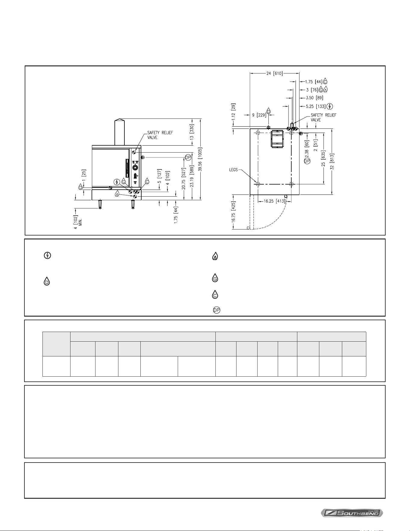
SERVICE CONNECTIONS
SERVICE CONNECTIONS
As continued product improvement is a policy of Southbend Steam, specications are subject to changge without notice.
UTILITY CONNECTIONS AND SPECIFICATIONS
Model
Gas Supply Pan Depth Minnimum Clearance
Shipping
Weight
BTU/HR. kW/HR. Supply Pipe Pressure (W.C.)
1” 2-1/2” 4” 6”
Left Right Back
SX-6G3
-SB
250 lbs.
[113 kg]
47,000 13.8
Natural
6” - 14”
(152 - 356 mm)
Propane
11” - 14”
(279 - 356 mm)
12 6 3 2
3”
[76 mm]
8”
[203 mm]
6”
[152 mm]
Terry System Cartridge Changes / Installation – “2-3 gallons of water MUST be purged at each cartridge change or new installation prior to
water supply being fed to the steamer. Failure to do so can result in component damage within the steamer which is not covered under warranty.
For additional guidance on proper installation, refer to install documentation provided with each Terry System and Replacement Cartridge Set.”
DISCLAIMER
WATER QUALITY STATEMENT
Water is the essential ingredient in steam equipment, water quality is the major factor aecting the performance of your appliance. Crown Steam Group oers a
Comprehensive Water Treatment System which exceeds our minimum water requirements. Proof of installation and proper cartridges replacement is required for
warranty coverage. Water supply to Crown Steam Group steamers must be within these guidelines.
Total dissolved solids.......................Less than 60 PPM Chlorine ............................Less than 1.5 PPM
Total alkalinity ........................................ Less than 20 PPM pH Factor .........................6.8 - 7.3
Silica ....................................................... Less than 13 PPM
Water which does not meet these standards should be treated with the installation of Middleby’s Water Treatment System. Call 919-762-1000 if you have questions
concerning your water meeting these parameters.
*Failure or malfunction of this appliance due to poor water quality is not covered under warranty.
Reference www.crownsteamgroup.com for complete warranty details and instructions.
– ELECTRICAL CONNECTION: Unless otherwise specied, eld
wire electrical connection to be 120 V, 60 Hz., single phase with
grounding wire. Furnished with 6 foot cord with 3 prong plug.
Maximum amps 2.0.
– DRAIN: 1” IPS piped to open oor drain. No solid connection.
Copper only. 24” maximum length before open air gap opening.
(No bends or elbows)
– GAS CONNECTION: 3/4” IPS supply line required. A gas
shut-o valve must be installed in supply piping convenient
and adjacent to appliance.
– GENERATOR WATER: 3/8” (10 mm) O.D. tubing at
25-50 psi (170-345 kPa).
– CONDENSING WATER: 3/8” (10 mm) O.D. tubing at
25-50 psi (170-345 kPa).
– DELIME PORT: 3/4” IPS
SERVICE CONNECTIONS
INSTALLATION & OPERATION MANUAL 10301A-SB REV 1 (09-22)
PAGE
5
OF 16
Gas Fired Steamer
Unpacking
IMMEDIATELY INSPECT FOR SHIPPING DAMAGE
Immediately after unpacking, check for possible shipping damage. If the appliance is found to be damaged, save the
packaging material and contact the carrier within 15 days of delivery.
We cannot assume responsibility for damage or loss incurred in transit.
Before installing, verify that the gas (natural or propane), the elevation from sea level and the electrical supply agree
with the specication on the data plate. NOTE: If this appliance is being installed above 2000 feet altitude, contact your
authorized service oce to assure that the proper orice size for your elevation has been installed.
INSTALLATION INSTRUCTIONS
Installation Codes and Standards
Installation must conform with local codes, or in the absence of local codes, with the National Fuel Gas Code,
ANSI Z223.1/NFPA 54, or the Natural Gas and Propane Installation Code, CSA B149.1, as applicable.
1. The appliance and its individual shut o valve must be disconnected from the gas supply piping system during any
pressure testing of that system at pressures in excess of 1/2 psi (3.5 kPa).
2. The appliance must be isolated from the gas supply piping system by closing its individual manual shut o valve
during any pressure testing of the gas supply piping system at test pressures equal to or less than 1/2 psi (3.5 kPa).
Electrical grounding must be provided in accordance with local codes, or in the absence of local codes, with the National
Electrical Code, ANSI/NFPA 70, or the Canadian Electrical Code, CSA C22.2, as applicable.
Ventilation must be provided in accordance with local codes, or in the absence of local codes, with ANSI/NFPA 96
Standard for Ventilation and Fire Protection of Commercial Cooking Operations.
INSTALLATION
NOTICE
If this equipment is being installed at over 2,000 feet altitude and was not so specied on order, contact service
department. Failure to install with proper orice sizing may void the warranty.
General
WARNING
ELECTRICAL GROUNDING INSTRUCTIONS
Units equipped with a three-prong (grounding) plug for your protection against shock hazard and should
be plugged directly into a properly grounded three-prong receptacle. Do not cut or remove the grounding
prong from this plug. (120V units only).
WIRING DIAGRAM FOR APPLIANCE IS LOCATED ON RIGHT HAND SIDE PANEL OF THE
COOKER CABINET.
Exhaust Fans and Canopies
Canopies are set over ranges, ovens, kettles, etc., for ventilation purposes. It is recommended that a canopy extend
6” past appliance and be located 6’ 6” from the oor. Filters should be installed at an angle of 45 degrees or more
with the horizontal. This position prevents dripping of grease and facilitates collecting the run-o grease in a drip pan,
usually installed with the lter. A strong exhaust fan tends to create a vacuum in the room and may interfere with burner
performance or may extinguish pilot ames. Makeup air openings approximately equal to the fan area will relieve such
vacuum. In case of unsatisfactory performance on any appliance, check with the exhaust fan in the “OFF” position.
INSTALLATION & OPERATION MANUAL 10301A-SB REV 1 (09-22)
PAGE
6
OF 16
Gas Fired Steamer
Wall Exhaust Fan
The exhaust fan should be installed at least two feet above the vent opening at the top of the unit.
Clearances
Adequate clearance must be provided in aisle and at the side and back. Adequate clearances for air openings into the
combustion chamber must be provided, as well as for serviceability for use on noncombustible oors. Minimum clearance
from combustible and noncombustible construction, 3 inches on left side, 8 inches on right side and 6 inches from back.
To Install
1. Uncrate carefully. Report any hidden freight damage to the freight company immediately.
2. Set the unit in place. Be certain to maintain the minimum clearances from combustibles and non-combustibles.
3. Level appliance using spirit level. Should anged adjustable feet be provided, anchor to oor using proper anchoring devices.
4. Seal bolts and anged feet with Silastic or other equivalent compound.
5. Be certain to leave adequate clearances for cleaning, maintenance and service.
WARNING
Never use an open ame to check for gas leaks. Check all connections for leaks using soapy water before use.
WARNING
These procedures must be followed by qualied personnel or warranty will be voided. An open gap oor drain
is required immediately below the appliance drain.
Gas Connection
1. The Serial and Rating Plate on the unit indicates the type of gas your unit is equipped to burn. DO NOT connect to
any other gas type.
2. A 3/4” NPT line is provided at rear for the connection. Each compartment is equipped with an internal pressure
regulator which is set at 3.5” W.C. manifold pressure for natural gas and 9.0” W.C. for propane gas. Use 1/8” pipe tap
on the burner manifold for checking pressure.
An adequate gas supply is imperative. Undersized or low pressure lines will restrict the volume of gas required for
satisfactory performance. A steady supply pressure, between 6” W.C. and 14” W.C. for natural gas and between 11” W.C.
and 14” W.C. for propane gas is recommended. With all units operating simultaneously, the manifold pressure on all units
should not show any appreciable drop. Fluctuations of more than 25% on natural gas and 10% on propane gas will create
problems, aecting burner operation. Contact your gas company for correct supply line sizes.
Purge the supply line to clean out any dust, dirt or other foreign matter before connecting the line to the unit. se pipe
joint compound which is suitable for use with Propane on all threaded connections. A manual gas shut o valve for each
compartment is supplied with the unit.
Test pipe connections thoroughly for gas leaks.
NOTICE
If applicable, the vent from the gas appliance pressure regulator shall be installed to the outdoors in accordance
with local codes or, in the absence of local codes, with the National Fuel Gas Code, ANSI Z223.1 or the Natural Gas
Installation Code CAN/CGA-B149.1 or the propane installation code, CAN/CGA-B149.2, as applicable.
INSTALLATION
INSTALLATION & OPERATION MANUAL 10301A-SB REV 1 (09-22)
PAGE
7
OF 16
Gas Fired Steamer INSTALLATION
WARNING
Do not connect the steamer to the electrical supply until after the gas connection has been made.
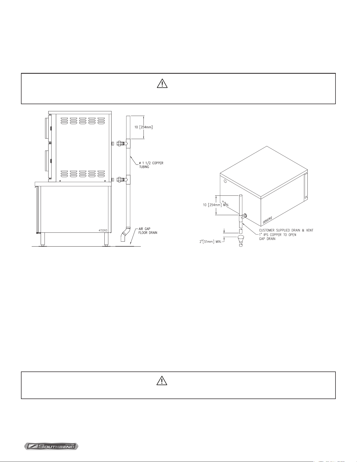
Drain Connection
The drain connection must be 1-1/2” (37.5 mm) IPS down, preferably with one or two elbows only, maximum length 6 feet
(1830 mm) horizontal and piped to an open gap type drain. Drain pipe should be copper. DO NOT use PVC pipe – PVC
pipe may lose its rigidity or glue may fail.
CAUTION
To avoid injury or damage to the steamer, do not connect solidly to any drain connection.
Figure 1 Figure 2
Water Quality
The water supply connected to the steam generator should meet the following guidelines:
Failure to comply with Water Quality Statement on page 4 may void the warranty.
Water supplies vary from one location to another. Other factors aecting steam generation are iron content, chlorides,
and dissolved gasses. A local water treatment specialist should be consulted before installing any steam generating
equipment.
Untreated water contains scale producing minerals which can precipitate onto the surfaces in the generator. Due to
the temperatures in the generator, the minerals can bake onto the surfaces and components. This can result in early
component failure and reduced product life.
Electrical Connection
120 VAC-60 Hz - Single Phase
Units with this electrical rating are factory supplied with a three-wire cord and three-prong plug which ts any standard
NEMA 5-15R 125 VAC, three-prong grounded receptacle. A separate 15 amp supply is needed for each unit.
INSTALLATION & OPERATION MANUAL 10301A-SB REV 1 (09-22)
PAGE
8
OF 16
Gas Fired SteamerINSTALLATION
Plumbing Connections
WARNING
Plumbing connections must comply with applicable sanitary, safety and plumbing codes.
The water supply inlets are provided with 3/8” (10 mm) compression ttings for 3/8” O.D. copper tubing. The water supply
line pressure should be 25 - 50 psi (170-345 kPa) for each line. The water supply to the generator tank(s) separate from
the water supply to the cooling system where steam is condensed before entering the drain line.
Install line strainers (not provided). A manual shuto valve for each supply line must be provided convenient to the steamer.
Treated water feeding the boiler inlet supply is recommended, and untreated water feeding the condensing water inlet.
Inlets are labelled on the back of the steamer
Cold Water Condenser
The steamer is equipped with a cold water condenser in the rear of the cooking chamber which helps to condense the
steam prior to discharge into drain. The steamer freely vents itself by the negative pressure created by the condensate
water drainage. This negative pressure prevents steam leakage around the door gasket and helps draw the steam
through the cooking compartment. Steam leakage at the door may indicate a plugged or improperly installed drain.
Water Conditioning
It is important that the water supply connected to this steamer be softened to no more than 2.0 grains of hardness
and have a pH of 6 to 7.5. This degree of hardness can be easily obtained with the use of a properly maintained water
softener. The use of a water meter will determine the water consumption and when the water softener needs regeneration
or recharging. Failure to comply with these water condition standards may void the warranty.
Untreated water contains scale producing minerals which can precipitate onto the surfaces in the generator. Due to
the temperatures in the generator, the minerals can bake onto the surfaces and components. This can result in early
component failure and reduced product life. Water level probes become coated with scale. Scale will bridge across the
probe insulator from the metal extension which senses the water level in the generator. Once this scale becomes wet, the
water level control is unable to maintain the proper water level in the generator.
STRAINERS and FILTERS will NOT remove minerals from the water.

INSTALLATION & OPERATION MANUAL 10301A-SB REV 1 (09-22)
PAGE
9
OF 16
Gas Fired Steamer
Performance Check
Once the steamer is installed and all mechanical connections have been made, thoroughly test the steamer before
operation.
1. Check that proper water, drain and electrical and gas connections have been made.
2. Turn main power switch ON. After approximately 12 minutes, the “READY” light should come on, indicating that the
water temperature is 205º Fahrenheit (97º Celsius).
3. Check that “Ignition” light comes on when the pilot burner is on.”
4. When the “READY” light comes on, set timer to the “5 minute” position. With door open, observe that no steam is
entering the compartment and that the “COOKING” light is OFF.
5. Close compartment door. The COOKING light should now be illuminated and steam should be heard entering the
compartment after about 45 seconds. “READY” light is OFF.
6. Ensure that water from cold water condenser is owing through the drain line.
7. Open compartment door and observe that steam supply to chamber is cut o. “READY” light should again come “ON”
as “COOKING” light goes “OFF.”
8. Close compartment door and let cooking cycle nish. When the timer returns to “0” position, a buzzer will sound
signalling the end of the cooking cycle. Buzzer must be manually turned o by setting the timer to its “OFF” position.
Performance Check
INSTALLATION & OPERATION MANUAL 10301A-SB REV 1 (09-22)
PAGE
10
OF 16
Gas Fired Steamer
OPERATION
WARNING
The steamer and its parts are hot. Use care when operating, cleaning or servicing the steamer. The cooking
compartment contains live steam. Stay clear when opening door.
Your steamer has been factory set when “ON” to maintain water temperature during the READY phase at approximately
205º Fahrenheit (97º Celsius) just below water boiling point.
Controls
Ready Pilot Light - When lit, indicates steam chamber has reached 205º Fahrenheit (97º Celsius) and is ready
for the cooking cycle.
Cooking Pilot Light - When lit, indicates that a cooking cycle is in progress.
Ignition Light - When lit, indicates that pilot burner has been ignited.
Timer - Set the cooking time (0 to 60 minutes) - steam cooking will begin when the door is closed.
The cooking cycle will be interrupted if the door is open during the cooking cycle; resume
cooking by closing the door.
MAIN POWER SWITCH
On - The generator will automatically ll and begin heating to the pre-set temperature.
O - The generator will drain.
Delime - Closes the drain valve while CLR liquid is being poured into the generator during the
Delime procedure.
Operating Instructions
WARNING
In the event of main burner ignition failure, a 5 minute purge period must be observed prior to re-establishing
ignition source. If so equipped, some units will automatically re-attempt ignition.
WARNING
In the event a gas odour is detected, shut down equipment at the main shut o valve and contact the local
gas company or gas supplier for service.
Lighting
1. Ensure power, gas and water supply is on.
2. Turn power switch “ON.”
3. Generator tank will begin lling with water.
4. Once water level has been reached, the ignition light should come on and remain on throughout the operation of the
appliance.
5. When “READY” light comes ON the steamer is ready for use.
OPERATION
INSTALLATION & OPERATION MANUAL 10301A-SB REV 1 (09-22)
PAGE
11
OF 16
Gas Fired Steamer OPERATION
NOTICE
The cooking compartments are operated independently of each other. Each has its own gas and water
supply and generator tank.
Shutdown
Stand By
1. Set timer to “OFF” position and leave door slightly open.
Complete Shutdown
1. Set timer to “OFF” and turn power switch “OFF.” Generator will drain automatically.
2. Turn water supply “OFF.”
3. Turn gas supply “OFF.”
4. Disconnect power supply.
STEAM COOKING
Your steamer eciently cooks vegetables or other foods for immediate serving. Steam cooking should be carefully time
controlled. Keep hot food holding time to a minimum to produce the most appetizing results. Prepare small batches, cook
only enough to start serving, then cook additional amounts to meet demand. Separate frozen foods into smaller pieces to
allow more ecient cooking.
Use a pan cover for pre-cooked frozen dishes that cannot be cooked in the covered containers in which they are packed
if they require more than 15 minutes of cooking time. When cover is used, approximately one-third additional cooking time
is necessary.
Cooking time for frozen foods depends on amount of defrosting required. If time permits, allow frozen foods to partially
thaw overnight in a refrigerator. This will reduce their cooking time.
PREPARATION
Prepare vegetables, fruits, meats, seafood and poultry normally by cleaning, separating, cutting, removing stems, etc.
Cook root vegetables in a perforated pan unless juices are being saved. Liquids can be collected in a solid 12” x 20” pan
placed under a perforated pan. Perforated pans are used for frankfurters, wieners and similar items when juices do not
need to be preserved. Solid pans are good for cooking puddings, rice and hot breakfast cereals. Vegetables and fruits
are cooked in solid pans in their own juices. Meats and poultry are cooked in solid pans to preserve their own juices or to
retain broth. Canned foods can be heated in their opened cans (cans placed in 12” x 20” solid pans) or the contents may
be poured into solid pans.
PAN
The steamer compartment is designed to accept combinations of the pan of 12” x 20” (either solid or perforated) as shown
on the following table.
MODEL DEPTH OF PAN NUMBER OF PANS
SX-6G3-SB
1" 12
2-1/2” 6
4" 3
6" 2
INSTALLATION & OPERATION MANUAL 10301A-SB REV 1 (09-22)
PAGE
12
OF 16
Gas Fired Steamer
Cleaning
At the end of each day, or between cooking cycles if necessary:
1. Turn main power switch OFF.
2. Remove pans and racks from compartment and wash in sink.
3. Wash compartment interior with clean water.
4. Use warm soapy water with a cloth or sponge to clean exposed bead of door gasket, rinse with warm clear water and
wipe with a dry cloth.
Wipe surfaces which touch door gasket with a cloth or sponge and warm soapy water, rinse with warm clear water
and wipe with a dry cloth. Do not apply food oils or petroleum solvents or lubricants directly to door gasket or surfaces
which touch door gasket.
5. Remove drain screens from inside compartment drains. Using a plastic bottle brush and mild detergent, clean
inside the drain opening ensuring there is no food residue or blockage. Clean the drain screen and replace in its
original position.
6. Leave door slightly open when steamer is not in use.
Weekly, or more often if necessary:
WARNING
Disconnect the unit from the power supply before cleaning or servicing appliance.
CAUTION
Never spray water into electric controls.
CAUTION
Do not use cleaning agents that are corrosive.
CAUTION
Live steam and accumulated hot water in the compartment may be released when the door is opened.
NOTICE
Contact the factory, the factory representative or a local service company to perform maintenance and
repairs should the appliance malfunction. Refer to warranty terms.
1. Clean exterior with a damp cloth and polish with a soft dry cloth.
2. Use a non-abrasive cleaner to remove discolorations.
3. Clean around burner air mixer and orice if lint has accumulated. Side cover must be removed to clean this area.
Monthly:
1. Clean around burner air mixers, louvered panels if grease or lint has accumulated.
Following daily and periodic maintenance procedures will enhance long-life for your equipment. Climatic conditions - salt
air - may require more thorough and frequent cleaning otherwise the life of the equipment could be adversely aected.
Use of cleaning agents that contain chloride, acids or salts which are corrosive may cause pitting and corrosion when
used over a period of time; this will reduce the life of the appliance.
Should pitting or corrosion occur, this is not covered by warranty.
Cleaning
INSTALLATION & OPERATION MANUAL 10301A-SB REV 1 (09-22)
PAGE
13
OF 16
Gas Fired Steamer Cleaning
CAUTION
Never spray water into electric controls.
CAUTION
Do Not use cleaning agents that are corrosive.
Follow the recommended cleaning instructions. Use a mild detergent, warm water and rinse thoroughly.
Stainless Steel
To remove normal dirt, grease or product residue from stainless steel, use ordinary soap and water (with or without
detergent) applied with a sponge or cloth. Dry thoroughly with a clean cloth. Never use vinegar or any corrosive cleaner.
To remove grease and food splatters or condensed vapours that have baked on the equipment, apply cleanser to a damp cloth or
sponge and rub cleanser on the metal in the direction of the polishing lines on the metal. Rubbing cleanser as gently as possible in
the direction of the polished lines will not mar the nish of the stainless steel. NEVER RUB WITH A CIRCULAR MOTION.
Soil and burnt deposits which do not respond to the above procedure can usually be removed by rubbing the surface with
SCOTCH-BRITE
TM
scouring pads or STAINLESS scouring pads. DO NOT USE ORDINARY STEEL WOOL as any particles left
on the surface will rust and further spoil the appearance of the nish. NEVER USE A WIRE BRUSH, STEEL SCOURING PAD
(EXCEPT STAINLESS), SCRAPPER, FILE OR OTHER STEEL TOOLS. Surfaces which are marred collect dirt more rapidly and
become more dicult to clean. Marring also increases the possibility of corrosive attack. Renishing may then be required.
To Remove Heat Tint
Darkened areas sometimes appear on the stainless steel surface where the area has been subjected to excessive heat.
These darkened areas are caused by thickening of the protective surface of the stainless steel and are not harmful. Heat tint
can normally be removed by the foregoing, but tint which does not respond to this procedure calls for a vigorous scouring in
the direction of the polish lines using SCOTCH-BRITE
TM
scouring pads or a STAINLESS scouring pad in combination with a
powdered cleanser. Heat tint action may be lessened by not applying or by reducing heat to equipment during slack periods.
Removal of Scale Deposits
It is recommended that your steamer be delimed once a month, or more often if necessary.
Should your steamer develop a heavy build-up of lime scale deposits, use the CLR TREATMENT KIT available from your
authorized servicer.
Before beginning deliming procedures, ensure that the water is not overowing into the cooking compartment.
Deliming Procedure
WARNING
Read and follow instructions on the CLR bottle. Use plastic or rubber gloves to avoid skin contact. If CLR comes
in contact with skin, rinse with clean water.
1. Drain steam generator by setting power switch to “OFF.” Set cooking timer to 0.
2. Turn power switch to DELIME. Keep the doors closed.
3. Unscrew brass deliming plug on right side of steamer. Insert hose in hole of port. Pour 20 ounces of solution into
generator slowly to avoid spillage. Remove hose. Screw deliming plug back so it seals tightly. Turn power switch to
on. (If there is no deliming plug on the side of the steamer, check with your local service agency for proper deliming
instructions of your unit.)
4. Allow steamer to remain in ready cycle for 1/2 hour, then turn power switch “OFF” and allow generator to drain.
5. Flush cycle. Turn power switch to “ON.” When ready light comes on, switch to “OFF” to fully drain the generator.
Repeat this step three times to completely ush generator.
6. Clean exterior and interior. Use a mild solution of soap and water. Rinse with clean water. Dry with a soft cloth.
LEAVE COMPARTMENT DOOR OPEN WHEN NOT IN USE.
The steamer is now ready for use. Turn o for overnight shutdown.
INSTALLATION & OPERATION MANUAL 10301A-SB REV 1 (09-22)
PAGE
14
OF 16
Gas Fired Steamer
Troubleshooting
Adjustments
Troubleshooting
WARNING
At least twice a year, have an authorized service person clean and adjust the unit for maximum performance.
WARNING
Adjustments and service work may be performed only by a qualied technician who is experienced in, and
knowledgeable with, the operation of commercial gas cooking equipment. However, to assure your condence,
contact your authorized service agency for reliable service, dependable advice or other assistance, and for
genuine factory parts.
All units are adjusted at the factory. In case of operation problems at initial installation, check type of gas and manifold
pressure and compare it with information on rating plate.
Troubleshooting
Pilot Light Does Not Come On
1. Gas supply to unit is “OFF.”
2. Manual shut o valve is “OFF.”
3. Power switch is not turned “ON.”
4. Probe not sensing the water level, will not call for ignition.
5. Ignitor or ignition module not functioning.
Burners Produce Carbon Deposits
1. Wrong orice size.
2. Wrong gas supply.
3. Incorrect pressure at supply.
4. Dirty primary air openings.
5. Not enough primary air.
Water Flows into Cooking Compartment
1. Probes not sensing water, thereby not operating ll solenoid.
2. Scale build-up on operating probe inside generator.
3. Water ll solenoid valve is not closed. Check for scale or foreign particles lodged in diaphragm or core tube of valve.
These problems are an indication of severe harmful water conditions which should be corrected immediately to avoid
damage to the components and performance of the steamer.

INSTALLATION & OPERATION MANUAL 10301A-SB REV 1 (09-22)
PAGE
15
OF 16
Gas Fired Steamer
Door Leaks
1. Check for damage to door gasket.
2. Clogged compartment drain or plumbing.
Water Accumulates in the Compartment
1. Compartment drain clogged.
Water Flows into Drain During Shut Down
1. Condensate solenoid valve and/or ll solenoid valve is not closed. Check for scale or foreign particles lodged in
diaphragm or core tube of valve.
Water Not Being Supplied to Generator
1. Water supply is “OFF.”
2. Supply water pressure too low.
3. Defective water ll solenoid valve.
4. Defective level control board.
5. Shortage of circuit between probes and body.
6. Check that drain solenoid is closed.
Troubleshooting
INSTALLATION & OPERATION MANUAL 10301A-SB REV 1 (09-22)
PAGE
16
OF 16
Gas Fired Steamer
SX-6G3-SB
Gas Fired Steamer
A product with the Southbend Steam name incorporates the best in durability and low maintenance. We all recognize,
however, that replacement parts and occasional professional service may be necessary to extend the useful life of this
appliance. When service is needed, contact a Southbend Steam Authorized Service Agency, or your dealer. To avoid
confusion, always refer to the model number, serial number, and type of your appliance.
SOUTHBEND STEAM
A Middleby Company
1100 Old Honeycutt Road Fuquay-Varina, North Carolina 27526 USA
www.southbendnc.com