eG9887 revised 11/18
eagle Foodservice equipment, eagle Mhc, specFAB, and retail Display are divisions of eagle Group. ©2018 by the eagle Group
• 100 Industrial Boulevard, Clayton, Delaware 19938-8903 U.S.A. • www.eaglegrp.com
• Phone: 302/653-3000 • (Foodservice) 800/441-8440 • (MHC/Retail) 800/637-5100
• Fax: 302/653-2065
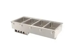
1) Cut holes as required in counter top and front panel. See chart for cut out sizes.
See figure 1 for cutout positioning.
2) Remove screws holding control panel to box and remove control panel to expose field-
wiring terminals.
3) Apply a bead of NSF listed silicone adhesive to underside of top flange. Pass control box
through top opening and work through cutout in front panel. Seat unit to counter top.
4) From underneath insert a long, flat head screwdriver into the slots in the locking angles.
Twist clockwise 120˚ to lock unit securely to top.
5) Install control box securely in front panel cutout with #8 sheet metal screws in top and
bottom flanges.
6) Make electrical connections at terminal block as required. Connect unit to dedicated
electrical circuit with properly sized circuit breaker that meets the requirements of
NEC Article 422 and any local electrical codes. See unit model/serial for electrical
ratings. Replace control panel and attach knobs.
Note: All units are shipped from the factory wired for single-phase operation; all but the
single-well units are field-convertible for three-phase operation, see wiring diagram
for details.
7) A drain manifold with ball valve is provided on all units with drains. Location of the valve
is left to the discretion of the installer*. Install provided pipe plug on end opposite ball
valve. Use of a suitable pipe-sealing compound is recommended. When tightening
connections, back up manifold fittings with a wrench to prevent damage to the manifold.
*on units with AutoFill
®
Water system, the ball valve will be located on the left end.
CAUTION
insPect contents iMMeDiAteLY AnD FiLe cLAiM With DeLiVerinG cArrier
For AnY DAMAGe. SAVe YOUr BOX AND ALL pACKINg MATerIALS.
You Are resPonsiBLe For DAMAGe to Your unit iF returneD iMProPerLY PAcKeD.
Installation must meet local electrical and plumbing codes. Installation
must allow access for service. Unit shall be accessible for servicing
from the bottom.
Please retain
this manual for
future reference.
replacement parts List
334567 . . . . . . . . . . . element 1600W @ 240V
334567 . . . . . . . . . . . element 1200W @ 208V
334571 . . . . . . . . . . . element 1200W @ 240V
334568 . . . . . . . . . . . element 1200W @ 120V
302353 . . . . . . . . . . . Light indicator
309750 . . . . . . . . . . . thermostatic control
301986 . . . . . . . . . . . control Knob
Parts are the same for all model numbers, quantities will vary.
part # description
replacement parts List— AutoFill
®
Water System
337968 . . . . . . . . . . . AutoFill
®
controller @ 120V
349784 . . . . . . . . . . . AutoFill
®
controller @ 208/240V
338518 . . . . . . . . . . . solenoid Valve @ 120V
349785 . . . . . . . . . . . solenoid Valve @ 208/240V
338390 . . . . . . . . . . . AutoFill
®
switch
338473 . . . . . . . . . . . AutoFill
®
reservoir
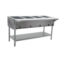
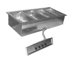
INSTALLATION/OperATINg INSTrUCTIONS
SGDI Drop-Ins
(continued on Page 2)
model top control umbilical
number cutout cutout length
sGDi-1 . . . . . 23 3/8˝ x 16 3/8˝ . . . . . 5˝ x 8˝ . . . . . . . . . 36˝
sGDi-2 . . . . . 23 3/8˝ x 30 3/8˝ . . . . . 5˝ x 17˝ . . . . . . . . 24˝
sGDi-3 . . . . . 23 3/8˝ x 44 3/8˝ . . . . . 5˝ x 17˝ . . . . . . . . 24˝
sGDi-4 . . . . . 23 3/8˝ x 57 3/8˝ . . . . . 5˝ x 33 7/8˝ . . . . . 24˝
sGDi-5 . . . . . 23 3/8˝ x 71 3/8˝ . . . . . 5˝ x 33 7/8˝ . . . . . 24˝
sGDi-6 . . . . . 23 3/8˝ x 85 3/8˝ . . . . . 5˝ x 33 7/8˝ . . . . . 24˝
** Denotes minimum installation spacing from
cutouts to vertical cabinet walls per uL listing.
figure 1
instruction sheet
#334591
single Phase
three Phase
A = element
B = Pilot Light
c = thermostatic control
Please see “replacement Parts List”
on front page for part numbers.
single Phase Amperage
Volts Watts L1 L2 L3
120 1200 30.00 n/a n/a
208 900 13.00 8.70 n/a
240 1200 15.00 10.00 n/a
208* 1200 17.50 12.00 n/a
240* 1600 20.00 13.50 n/a
3-Phase Amperage
Volts Watts L1 L2 L3
120 1200 n/a n/a n/a
208 900 4.33 7.50 7.50
240 1200 10.00 8.70 8.70
208* 1200 12.00 10.00 10.00
240* 1600 13.50 11.60 11.60
2
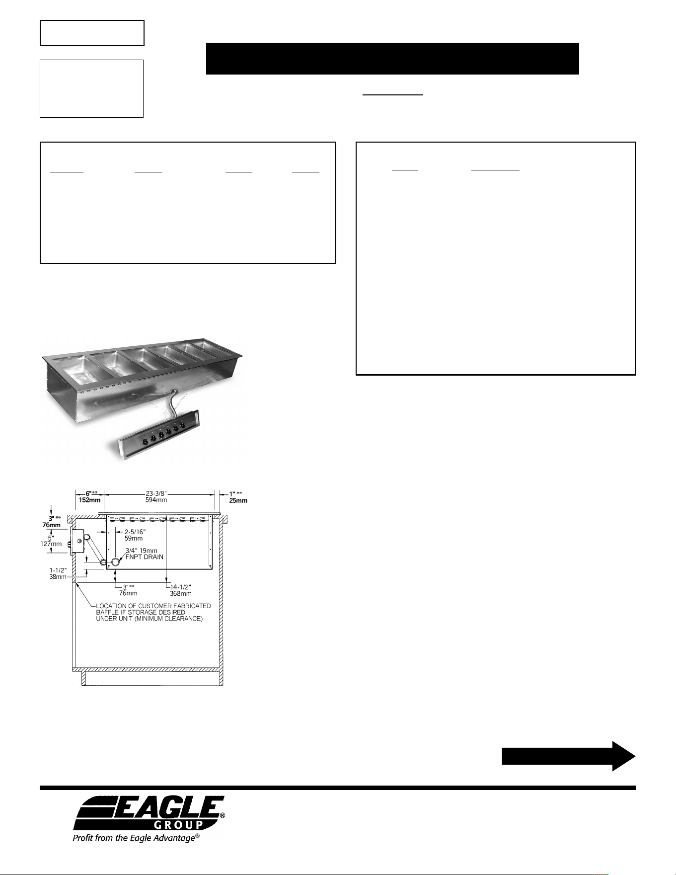
WIrINg DIAgrAMS FOr eLeCTrICIANS
Three-Well
SGDI Drop-Ins
Single-Well
Two-Well
single Phase
three Phase
A = element
B = Pilot Light
c = thermostatic control
Please see “replacement Parts List”
on front page for part numbers.
A = element
B = Pilot Light
c
= thermostatic control
Please see “replacement Parts List”
on front page for part numbers.
single Phase Amperage
Volts Watts L1 L2 L3
120 1200 20.00 n/a n/a
208 900 8.70 8.70 n/a
240 1200 10.00 10.00 n/a
208* 1200 12.00 12.00 n/a
240* 1600 13.50 13.50 n/a
3-Phase Amperage
Volts Watts L1 L2 L3
120 n/a n/a n/a n/a
208 900 4.33 4.33 7.50
240 1200 10.00 10.00 8.70
208* 1200 12.00 12.00 10.00
240* 1600 13.50 13.50 11.60
Volts Watts Amperage
L1 L2 L3
120 1200 10.00 n/a n/a
208 900 4.33 4.33 n/a
240 1200 5.00 5.00 n/a
208* 1200 6.00 6.00 n/a
240* 1600 7.00 7.00 n/a
single Phase
Four-Well
A = element
B = Pilot Light
c = thermostatic control
Please see “replacement Parts List”
on front page for part numbers.
three Phase
3-Phase Amperage
Volts Watts L1 L2 L3
120 1200 n/a n/a n/a
208 900 11.50 11.50 7.50
240 1200 13.30 13.30 8.70
208* 1200 15.30 15.30 10.00
240* 1600 17.70 17.70 11.60
single-Phase Amperage
Volts Watts L1 L2 L3
120 1200 n/a n/a n/a
208 900 17.30 8.70 n/a
240 1200 20.00 10.00 n/a
208* 1200 17.50 12.00 n/a
240* 1600 20.00 13.50 n/a
(continued on Page 3)
AutoFill
®
Water System
3
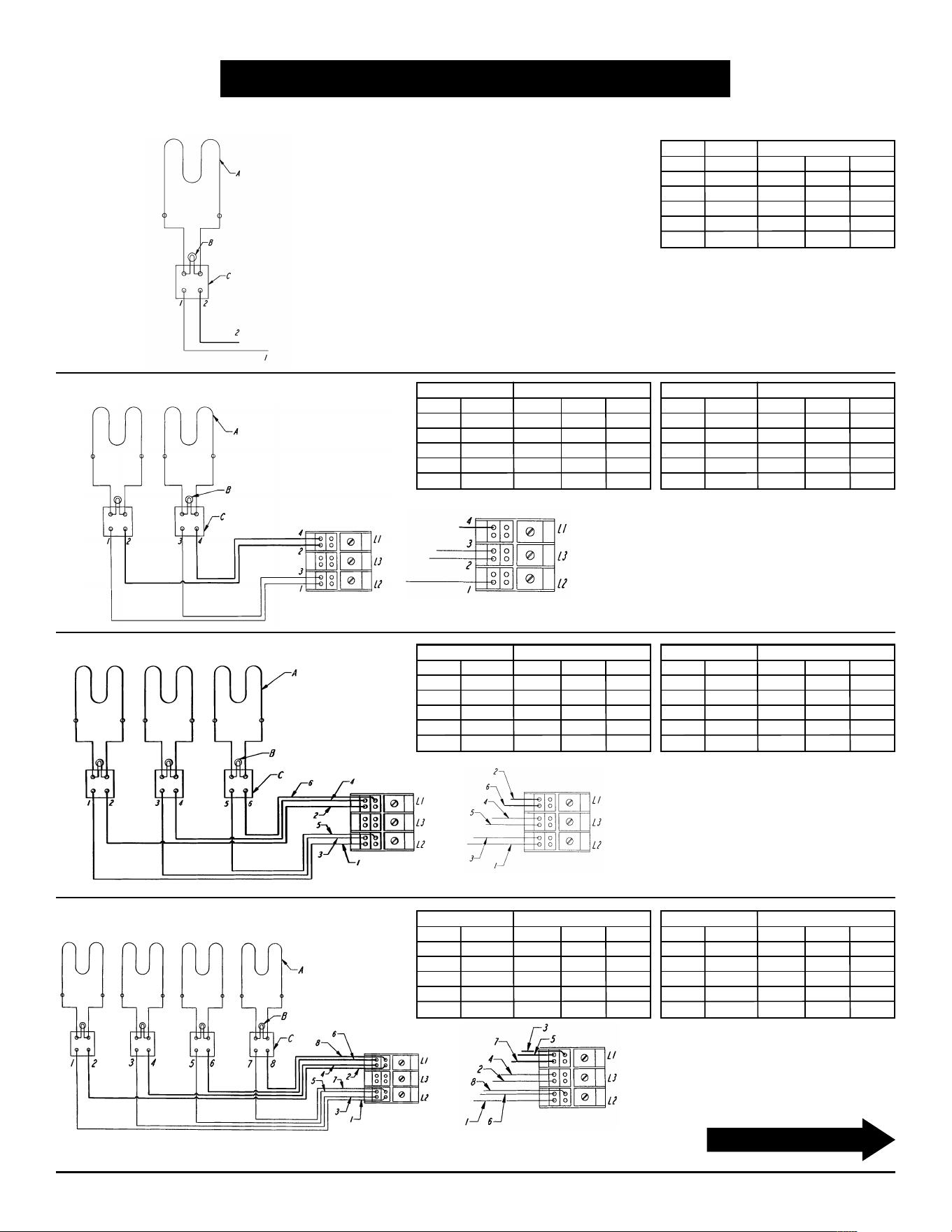
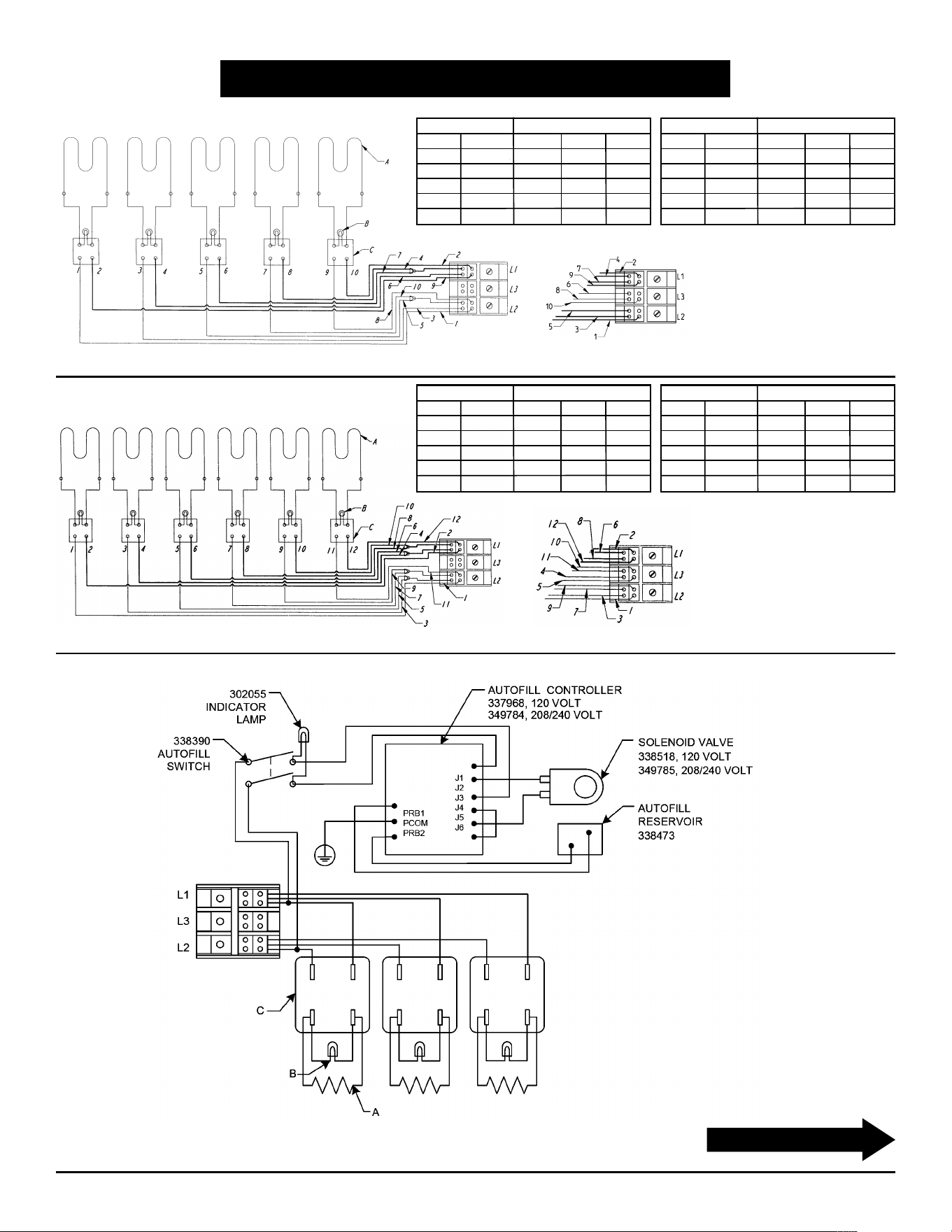
WIrINg DIAgrAMS FOr eLeCTrICIANS
SGDI Drop-Ins
A = element
B = Pilot Light
c
= thermostatic control
Please see “replacement Parts List”
on front page for part numbers.
A = element
B = Pilot Light
c = thermostatic control
Please see “replacement Parts List”
on front page for part numbers.
A = element
B = Pilot Light
c = thermostatic control
(Note: Wiring of AutoFill
®
with 3-well unit shown. Wiring similar on 1- to 6-well units.)
Five-Well
three Phasesingle Phase
three Phase
single Phase
Six-Well
single Phase Amperage
Volts Watts L1 L2 L3
120 1200 n/a n/a n/a
208 900 26.00 26.00 n/a
240 1200 30.00 30.00 n/a
208* 1200 35.00 35.00 n/a
240* 1600 40.00 40.00 n/a
3-Phase Amperage
Volts Watts L1 L2 L3
120 1200 n/a n/a n/a
208 900 15.00 15.00 15.00
240 1200 17.30 17.30 17.30
208* 1200 20.00 20.00 20.00
240* 1600 23.10 23.10 23.10
3-Phase Amperage
Volts Watts L1 L2 L3
120 1200 n/a n/a n/a
208 900 15.00 11.50 11.20
240 1200 17.30 13.30 13.00
208* 1200 20.00 15.30 15.00
240* 1600 23.10 17.60 17.30
single Phase Amperage
Volts Watts L1 L2 L3
120 1200 n/a n/a n/a
208 900 21.60 21.60 n/a
240 1200 25.00 25.00 n/a
208* 1200 29.00 29.00 n/a
240* 1600 33.50 33.50 n/a
(continued on back page)
eagle Foodservice equipment, eagle Mhc, specFAB, and retail Display are divisions of eagle Group. ©2018 by the eagle Group
• 100 Industrial Boulevard, Clayton, Delaware 19938-8903 U.S.A. • www.eaglegrp.com
• Phone: 302/653-3000 • (Foodservice) 800/441-8440 • (MHC/Retail) 800/637-5100
• Fax: 302/653-2065
OperATINg INSTrUCTIONS
SGDI Drop-Ins
Wet Operation with Cover
the above instructions are starting suggestions only and may be changed to suit your individual needs. With so many different
applications for this item, it is impossible to have standard settings to suit all applications.
Note: if unit is used dry, the bottom of receptacle will take on a brown colored appearance where the heater is located. the
discoloration will not come off with normal cleaning procedures, but in no way affects the operation of the unit.
CAUTION
1. this equipment is designed and sold for commercial use only by personnel trained and experienced in its operation and is not
sold for consumer use in and around the home nor for use directly by the general public in food service location.
2. Do not immerse unit in water.
3. All repairs should be done by an authorized service center.
4. unit should be turned off when not in use. it is recommended that unit be disconnected from power supply by shutting off
power supply.
The Food Warmer will work most efficiently when used with water in the well. The hot water will give a better distribution of heat and
help keep food from drying out. It is not designed for cooking foods but merely to keep hot foods at desired temperatures for serving.
1) Fill a well with hot water to 1˝. This may take some time since wells are connected via manifold.
2) Set dial to highest position for 45 minutes with well covered to preheat unit, place food pan with hot precooked food into well and cover food
pans with lids.
3) Adjust to desired setting for proper food temperature. This will vary with the type of food, type of food pans and individual serving temperature.
The FDA recommends a minimum temperature of 135˚F be maintained in food product. Consult local health codes.
4) To increase temperature, turn knob toward highest setting. To decrease, turn knob toward lowest setting.
5) Drain water, clean well and wipe dry every 24 hours of operation. Water may have to be added to well during operation depending on operating
time and temperature setting.
6) Food pans should be covered to maintain temperature when food is not being served and to prevent food from drying out.
AutoFill
®
Water System
(End)
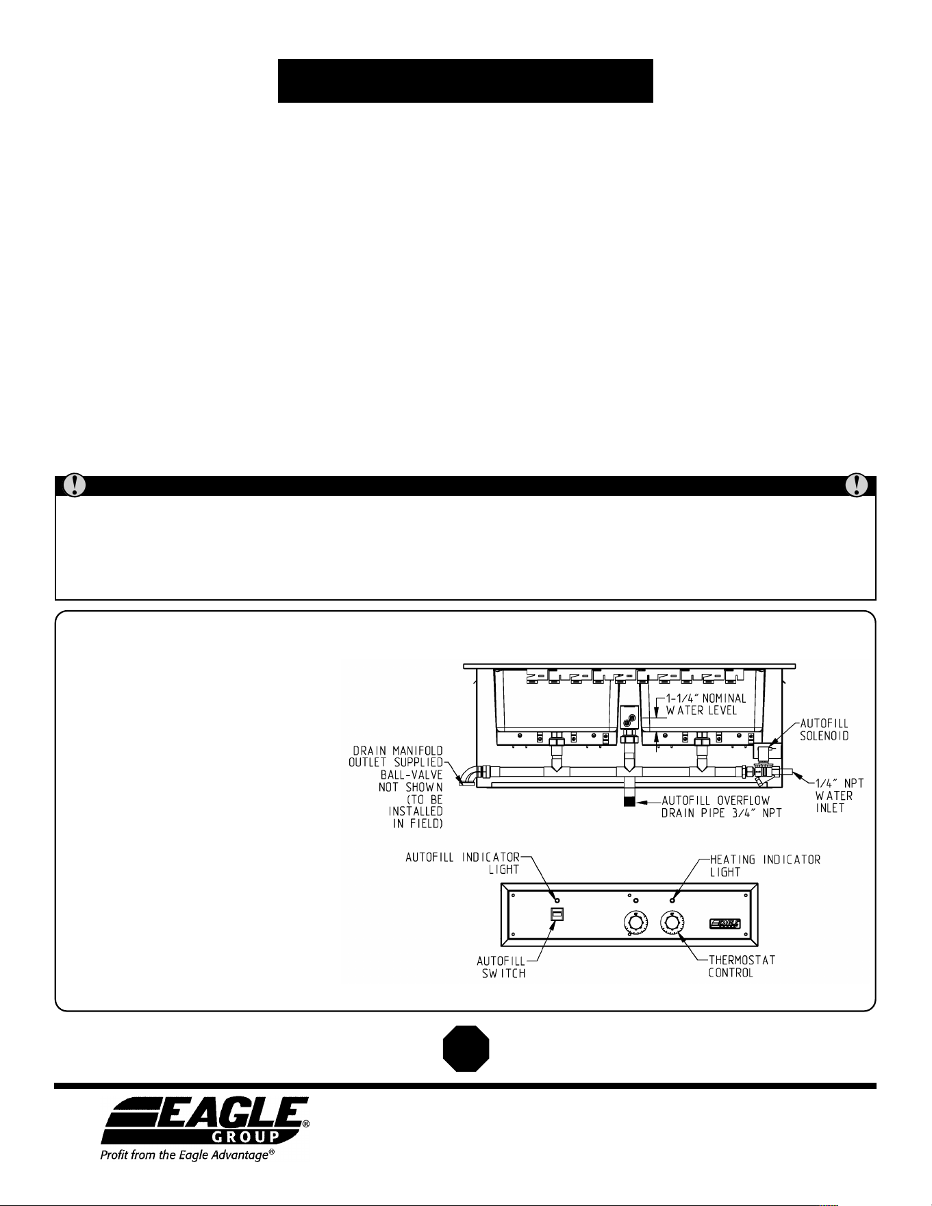
1. Ensure the unit is level left-to-right and
front-to-back.
Note: If unit is not level, the amount of
water will differ in wells.
2. Attach a continuous flowing hot water
source to the
1
⁄4˝ NPT water connection inlet.
3. Connect the drain and overflow to a vented
waste drain.
4. Turn water source on and the AutoFill
®
ON/OFF switch to “ON”. (The solenoid will
make a “pop” sound the first time this is
turned on.) The AutoFill
®
system will fill and
maintain the proper water level in all wells.
If there is a desire to run the unit without
automatically filling the wells with water,
simply turn the ON/OFF switch to the “OFF”
position. The AutoFill
®
system runs
independently of the hot wells, so the wells
are still operational.