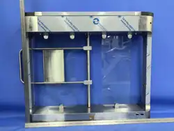

Swing Speed Gate
Quick Guide
V1.00

Contents
Preface .................................................................................................................. 1
Legal
Statement
..................................................................................................... 2
Safety
Precautions ................................................................................................. 4
1.
Packing List ................................................................................................... 8
2.
Introduction .................................................................................................. 9
2.1.1
Whole Unit
...................................................................................... 9
2.1.2
Control
Board
................................................................................ 10
2.1.3
Access
Control
Board
..................................................................... 14
3.
Device
Installation .......................................................................................
15
3.1
Installation Preparation ......................................................................... 16
3.2
Install Barriers........................................................................................ 17
3.3
Secure the Gate ..................................................................................... 20
3.4
Wiring.................................................................................................... 21
4.
Startup ........................................................................................................ 26
5.
Web
Login ...................................................................................................
27
6.
Remote
Control
Operations
......................................................................... 27
6.1
Remote
Control
Pairing
.......................................................................... 27
6.2
Restore
Factory
Defaults
......................................................................... 28

1
Preface
The content of this section is designed to ensure that users use the product correctly to prevent
dangers or property loss caused by improper operation. Before using this product, be sure to
read this manual carefully. Please keep this manual properly for future reference.
About This Manual
⚫
We recommend that you use this manual under the guidance of a professional.
⚫
This manual is designed for use with multiple product models, and it is not possible to list the
appearance and functions of each product individually. Please refer to the actual product for
use.
⚫
This manual is intended for multiple software versions, and the illustrations and descriptions
in this manual may be different from the actual GUI and functions of the software.
⚫
Despite our best efforts, technical or typographical errors may exist in this manual. Uniview
cannot be held responsible for any such errors and reserves the right to change the manual
without prior notice.
⚫
Users are fully responsible for the damages and losses that arise due to improper operation.
⚫
Uniview reserves the right to change any information in this manual without any prior notice
or indication. Due to such reasons as product version upgrade or regulatory requirement of
relevant regions, this manual will be periodically updated.
⚫
This manual will be updated in real time according to the laws and regulations of the relevant
regions. For specific details, please refer to the product's paper copy, QR code, or official
website. In case of any discrepancy between the paper copy and the electronic version, the
electronic version shall prevail.
About This Product
If the product you have chosen is a video product, please strictly adhere to the applicable laws
and regulations. You can visit our official website to inquire about the relevant content.
Instructions
for
Use
⚫
This document serves as a guide for use only. All statements, information, and suggestions
contained in this document do not constitute any express or implied warranty.
⚫
We assume no responsibility for any special, incidental, consequential, or indirect damages
resulting from the use of this manual or the use of our products, including but not limited to
losses due to loss of business profits, data or document loss, and product malfunction or
information leakage caused by cyber-attack, hacker attack, and virus infections.
⚫
Due to uncertain factors such as the physical environment, there may be discrepancies
between the actual values of some data and the reference values provided in the manual. In
case of any questions or disputes, the company's final interpretation shall prevail.
Formatting Conventions
The UI formatting conventions used in this document are as follows:
2
Format
Meaning
Bold
Bold means UI elements (button names, menu names, window names, etc.),
e.g., Click Save.
>
Indicate a sequence of actions, e.g., click Device Management > Add Device,
which means first click Device Management, and then click Add Device.
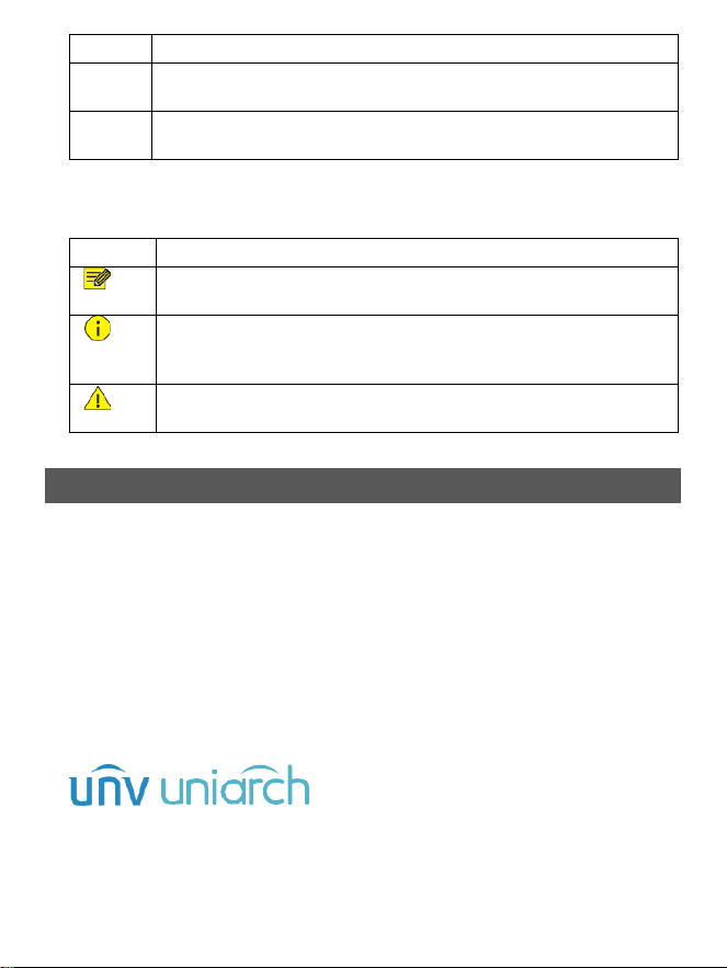
Symbol Conventions
This document uses various distinctive symbols to highlight areas that require special attention
during the operation process. The meanings of these symbols are as follows:
Symbol
Meaning
NOTE: Provides tips and additional information related to the operation and
use of the product.
CAUTION: Alerts to matters that requires attention during operation, as
improper handling may lead to product damage, data loss, or functional
abnormalities.
WARNING: The annotations following this symbol demand extra attention, as
improper handling could potentially cause personal injury.
Legal Statement
Copyright Statement
© 2025-2026
Zhejiang
Uniview
Technologies.,
Co.,
Ltd.
All
rights
reserved.
All parts of this document, including but not limited to text, images, and graphics, are
copyrighted and belong to Zhejiang Uniview Technologies Co., Ltd (hereinafter referred to as
“Uniview” "we" “us”). Without our written permission, no organization or individual may excerpt,
copy, translate, modify, or disseminate any part or all of the content of this manual in any form.
The products described in this manual may contain software copyrighted by us and any potential
licensors. Without the permission of the relevant rights holders, no one may copy, distribute,
modify, excerpt, decompile, disassemble, decrypt, reverse engineer, rent, transfer, sublicense, or
engage in any other actions that infringe upon the software copyright in any form.
Trademark Acknowledgements
are trademarks or registered trademarks of Uniview.
All other trademarks, products, services and companies in this manual or the product described
in this manual are the property of their respective owners.
Export Compliance Statement

3
Uniview complies with applicable export control laws and regulations worldwide, including that
of the People's Republic of China and the United States, and abides by relevant regulations
relating to the export, re-export and transfer of hardware, software and technology. Regarding
the product described in this manual, Uniview asks you to fully understand and strictly abide by
the applicable export laws and regulations worldwide.
EU
Authorised
Representative
UNV Technology EUROPE B.V. Treubstraa 1, 2288 EG, Rijswijk, Netherlands.
If you have any feedback, please contact us at [email protected].
Disclaimer of Liability
⚫
We assume no responsibility and offer no compensation for any special, incidental,
consequential, or indirect damages resulting from the use of this manual or our products,
including but not limited to losses related to lost business profits, data, or document loss.
⚫
The product described in this manual is provided on an "as is" basis. Unless required by
applicable law, this manual is only for informational purpose, and all statements, information,
and recommendations in this manual are presented without warranty of any kind, expressed
or implied, including, but not limited to, merchantability, satisfaction with quality, fitness for
a particular purpose, and noninfringement.
⚫
Users must assume total responsibility and all risks for connecting the product to the Internet,
including, but not limited to, network attack, hacking, and virus. Uniview strongly
recommends that users take all necessary measures to enhance the protection of network,
device, data and personal information. Uniview disclaims any liability related thereto but will
readily provide necessary security related support.
⚫
To the extent not prohibited by applicable law, in no event will Uniview and its employees,
licensors, subsidiary, affiliates be liable for results arising out of using or inability to use the
product or service, including, not limited to, loss of profits and any other commercial
damages or losses, loss of data, procurement of substitute goods or services; property
damage, personal injury, business interruption, loss of business information, or any special,
direct, indirect, incidental, consequential, pecuniary, coverage, exemplary, subsidiary losses,
however caused and on any theory of liability, whether in contract, strict liability or tort
(including negligence or otherwise) in any way out of the use of the product, even if Uniview
has been advised of the possibility of such damages (other than as may be required by
applicable law in cases involving personal injury, incidental or subsidiary damage).
⚫
To the extent allowed by applicable law, in no event shall Uniview’s total liability to you for all
damages for the product described in this manual (other than as may be required by
applicable law in cases involving personal injury) exceed the amount of money that you have
paid for the product.
⚫
When using this product, please strictly adhere to the applicable laws and regulations to
avoid infringing upon the rights of third parties, including but not limited to intellectual
property rights, data rights, or other privacy rights. You must also not use this product for the
purposes of developing or facilitating the use of weapons of mass destruction, biological or
chemical weapons, nuclear weapons, or for any other purposes that violate international
norms and regulations.

4
Privacy Protection Reminder
Uniview complies with appropriate privacy protection laws and is committed to protecting user
privacy. You may want to read our full privacy policy at our website and get to know the ways we
process your personal information. Please be aware, using the product described in this manual
may involve the collection of personal information such as face, fingerprint, license plate number,
email, phone number, GPS. Please abide by your local laws and regulations while using the
product.
Safety
Precautions
The device must be installed, serviced and maintained by a trained professional with necessary
safety knowledge and skills. Before you start using the device, please read through this guide
carefully
and
make
sure
all
applicable
requirements
are
met
to
avoid
danger
and
loss
of
property.
Storage, Transportation, and Use
⚫
Store or use the device in a proper environment that meets environmental requirements,
including and not limited to, temperature, humidity, dust, corrosive gases, electromagnetic
radiation, etc.
⚫
Make
sure
the
device
is
securely
installed
or
placed
on
a
flat
surface
to
prevent
falling.
⚫
Unless otherwise specified, do not stack devices.
⚫
Ensure good ventilation in the operating environment. Do not cover the vents on the device.
Allow adequate space for ventilation.
⚫
Protect
the
device
from
liquid
of
any
kind.
⚫
Make sure the power supply provides a stable voltage that meets the power requirements of
the device. Make sure the power supply's output power exceeds the total maximum power of
all the connected devices.
⚫
Verify
that
the
device
is
properly
installed
before
connecting
it
to
power.
⚫
Do not remove the seal from the device body without consulting Uniview first. Do not attempt
to service the product yourself. Contact a trained professional for maintenance.
⚫
Always
disconnect
the
device
from
power
before
attempting
to
move
the
device.
⚫
Take proper waterproof measures in accordance with requirements before using the device
outdoors.
Power
Requirements
⚫
Install and use the device in strict accordance with your local electrical safety regulations.
⚫
Use a UL certified power supply that meets LPS requirements if an adapter is used.
⚫
Use
the
recommended
cordset
(power
cord)
in
accordance
with
the
specified
ratings.
⚫
Only
use
the
power
adapter
supplied
with
your
device.
⚫
Use
a
mains
socket
outlet
with
a
protective
earthing
(grounding)
connection.
⚫
Ground
your
device
properly
if
the
device
is
intended
to
be
grounded.
Battery
Safety

5
Please
use
batteries
properly;
otherwise,
there
is
a
risk
of
fire
or
explosion.
⚫
Warning:
Using
incorrect
battery
models
can
lead
to
explosion.
⚫
If you need to replace the battery, it is recommended that you go to an authorized service
center or have it replaced under professional supervision. We shall not be held responsible
for any issues arising from unauthorized battery replacement.
⚫
When replacing the battery, be sure to use a battery of the same type as the original! Using
the wrong model for replacement (such as certain types of lithium batteries) may cause safety
protection to fail.
⚫
Batteries must not be exposed to overheat environments such as sunlight, fire, as this may
lead to fire, explosion, or combustion.
⚫
Do not dispose of batteries in fire or heating appliances. Do not squeeze, bend, or cut batteries,
as it may cause explosion.
⚫
Do not expose batteries to extremely high or low temperatures, or to very low-pressure
environments, as this may cause explosion or leakage of flammable liquid/gas.
⚫
Dispose of the used battery according to your local regulations or the battery manufacturer's
instructions.
⚫
For products or the included remote control containing a button cell battery: Do not ingest
the battery - chemical burn hazard! If swallowed, a button cell battery can cause severe
internal burns within 2 hours and may be fatal. Precautions (including but not limited to):
➢
Keep
new
and
used
batteries
away
from
children.
➢
Stop using the product and keep it away from children if the battery compartment is not
securely closed.
➢
If you suspect that a battery may have been swallowed or inserted inside any part of the
body, seek immediate medical attention.
Network
Security
Please take all necessary measures to enhance network security for your device.
The following are necessary measures for the network security of your device:
⚫
Change default password and set strong password: You are strongly recommended to change
the default password after your first login and set a strong password of at least nine characters
including all three elements: digits, letters and special characters.
➢
Do not include the account name or the reverse of the account name.
➢
Avoid using consecutive characters, such as 123, abc, etc.
➢
Do not use overlapping characters, such as 111, aaa, etc.
⚫
Keep firmware up to date: It is recommended that your device is always upgraded to the latest
version for the latest functions and better security. Visit Uniview's official website or contact
your local dealer for the latest firmware.
The
following
are
recommendations
for
enhancing
network
security
of
your
device:
⚫
Change password regularly: Change your device password on a regular basis and keep the
password safe. Make sure only the authorized user can log in to the device.
⚫
Enable HTTPS/SSL: Use SSL certificate to encrypt HTTP communications and ensure data
security.
⚫
Enable IP address filtering: Allow access only from the specified IP addresses.

6
⚫
Minimum port mapping: Configure your router or firewall to open a minimum set of ports to
the WAN and keep only the necessary port mappings. Never set the device as the DMZ host
or configure a full cone NAT.
⚫
Disable the automatic login and save password features: If multiple users have access to your
computer, it is recommended that you disable these features to prevent unauthorized access.
⚫
Choose username and password discretely: Avoid using the username and password of your
social media, bank, email account, etc, as the username and password of your device, in case
your social media, bank and email account information is leaked.
⚫
Restrict user permissions: If more than one user needs access to your system, make sure each
user is granted only the necessary permissions.
⚫
Disable UPnP: When UPnP is enabled, the router will automatically map internal ports, and
the system will automatically forward port data, which results in the risks of data leakage.
Therefore, it is recommended to disable UPnP if HTTP and TCP port mapping have been
enabled manually on your router.
⚫
SNMP: Disable
SNMP
if
you
do
not
use
it. If
you do
use
it,
then
SNMPv3
is
recommended.
⚫
Multicast: Multicast is intended to transmit video to multiple devices. If you do not use this
function, it is recommended you disable multicast on your network.
⚫
Check logs: Check your device logs regularly to detect unauthorized access or abnormal
operations.
⚫
Physical protection: Keep the device in a locked room or cabinet to prevent unauthorized
physical access.
⚫
Isolate video surveillance network: Isolating your video surveillance network with other
service networks helps prevent unauthorized access to devices in your security system from
other service networks.
Learn More
You may also obtain security information under Security Response Center at Uniview's official
website.
Avertissement de l’utilisation de la batterie
⚫
Lorsque
utiliser
la
batterie,
évitez:
➢
Température et pression d'air extrêmement élevées ou basses pendant l'utilisation, le
stockage et le transport.
➢
Remplacement de la batterie.
⚫
Utilisez la batterie correctement. Mauvaise utilisation de la batterie comme celles
mentionnées ici, peut entraîner des risques d’incendie, d’explosion ou de fuite liquide de gaz
inflammables.
➢
Remplacer la batterie par un type incorrect;
➢
Disposer d’une batterie dans le feu ou un four chaud, écraser mécaniquement ou couper
la batterie;
⚫
Disposer la batterie utilisée conformément à vos règlements locaux ou aux instructions du
fabricant de la batterie.
Regulatory
Compliance
FCC Statements
7
This device complies with Part 15 of the FCC Rules. Operation is subject to the following two
conditions: (1) this device may not cause harmful interference, and (2) this device must accept
any interference received, including interference that may cause undesired operation.
Visit https://global.uniview.com/Support/Download_Center/Product_Installation/Declaration/
for SDoC.
Caution: The user is cautioned that changes or modifications not expressly approved by the party
responsible for compliance could void the user's authority to operate the equipment.
NOTE: This equipment has been tested and found to comply with the limits for a Class A digital
device, pursuant to part 15 of the FCC Rules. These limits are designed to provide reasonable
protection against harmful interference when the equipment is operated in a commercial
environment. This equipment generates, uses, and can radiate radio frequency energy and, if not
installed and used in accordance with the instruction manual, may cause harmful interference
to radio communications. Operation of this equipment in a residential area is likely to cause
harmful interference in which case the user will be required to correct the interference at his own
expense.
This equipment complies with FCC radiation exposure limits set forth for an uncontrolled
environment. This equipment should be installed and operated with a minimum distance of 20cm
between the radiator and any part of your body.
LVD/EMC
Directive
This product complies with the European Low Voltage Directive 2014/35/EU
and
EMC
Directive
2014/30/EU.
WEEE
Directive–2012/19/EU
The product this manual refers to is covered by the Waste Electrical & Electronic
Equipment
(WEEE)
Directive
and
must
be
disposed
of
in
a
responsible
manner.
Battery
Regulation-
(EU)
2023/1542
Battery in the product complies with the European Battery Regulation (EU)
2023/1542. For proper recycling, return the battery to your supplier or to a
designated collection point.
8
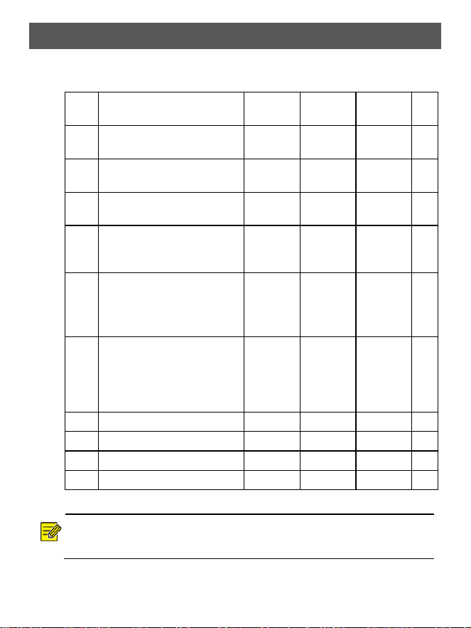
1.
Packing List
Contact your local dealer if the package is damaged or incomplete. The package
contents may vary with device model.
No.
Name
Left
Pedestal
Middle
Pedestal
Right
Pedestal
Unit
1
Swing Speed Gate (hereafter
referred to as “gate”)
1
1
1
Set
2
Control board bridging network
cable (white)
0
1
1
PCS
3
Access control board bridging
network cable (black)
0
1
1
PCS
4
Bridging power cable
(hereinafter referred to as
“bridging cable”)
0
1
1
PCS
5
Verification terminal power
adapter cable
(hereafter
referred
to
as
“adapter cable”)
1
2
1
PCS
6
Access control board &
verification terminal signal
extension cable (hereinafter
referred to as “extension
cable”)
1
2
1
PCS
7
M12*100
expansion
bolt
4
4
4
PCS
8
Hex
key
0
0
1
PCS
9
Cable terminal kit
1
2
1
Bag
10
Product documents
0
0
1
Set
NOTE!
All included accessories are placed in a bubble bag hung on the post.
9
2.
Introduction
Dimensions and structures may vary between different models. Please refer to your
device.
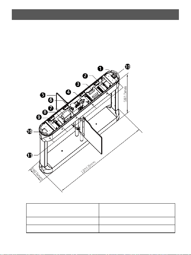
2.1.1
Whole
Unit
Taking the middle pedestal as an example, the internal structure after removing the
top cover is shown below. Please refer to your device for specifics.
1. Remote receiver: Not applicable to
the left pedestal
2. Sub access control board
3.
Control
board
4.
Speaker
5.
#Barrier
6.
Motor
10
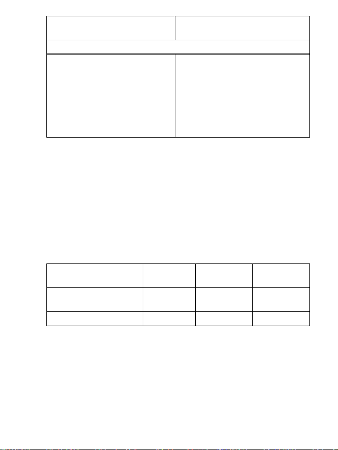
7. Air circuit breaker: Not applicable
to the left pedestal
8.
Tamper
prevention
switch
9.
Main
access
control
board
10.
Access indicator
⚫
Steady
green:
Normal
operation
⚫ Flash red: Abnormal condition
detected (e.g., unauthorized
entry)
11.
*Infrared
receivers/transmitters:
⚫ Left pedestal: 6 infrared
transmitters
⚫
Right
pedestal:
6
infrared
receivers
⚫ Middle pedestal: 6
infrared
transmitters + 6 infrared receivers
*
indicates that
the quantity may
vary with
the
gate
model.
Please refer to
your device.
*
indicates that the component is not included as standard and must be purchased
separately. The illustration shows how it looks when installed.
2.1.2
Control
Board
Control boards include main control board 1, main control board 2, and sub control
board.
Main control board 1 and main control board 2 are pre-connected via mating
connectors before shipment.
Control board configuration inside the gate is as follows:
Configuration
Left
Pedestal
Middle
Pedestal
Right
Pedestal
Main control board 1 +
Main control board 2
/
Included
Included
Sub control board
Included
Included
/
11
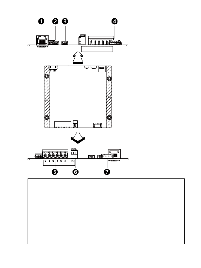
1
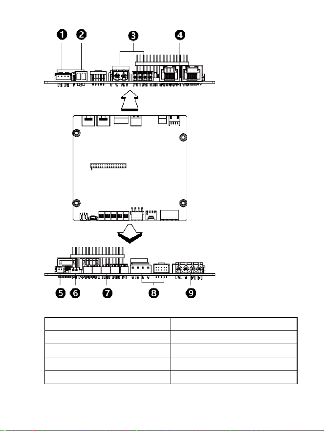
Main Control Board 1
1. Control board bridging network
cable interface
2.
Lower
light
curtain
interface
3.
Upper
light
curtain
interface
4.
Remote
receiver
interface
5. With access control board: Connects to the RS485 interface on the main
access control board
Without access control board: Connects to the RS485 interface on the
verification terminal
Pinout (from left to right):
IO–,
IO+,
RS485B,
RS485A,
GND,
12V
6.
Emergency
door
opening
interface
7.
Access
indicator
light
interface
12
2
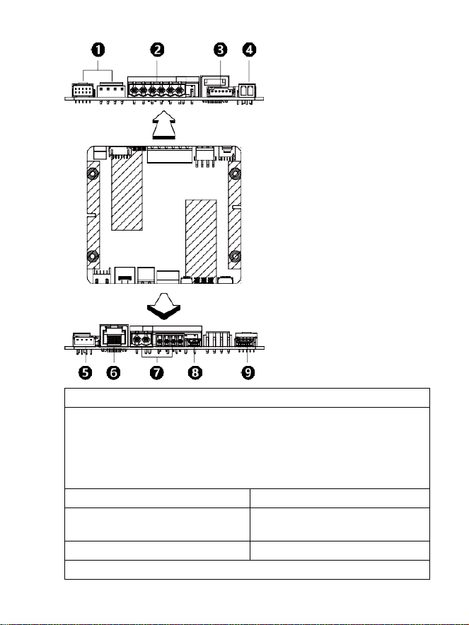
Main Control Board 2
1.
Fan
interface
(reserved)
2. Supercapacitor interface
3.
Bridging
power
interface
4. Network interface
5. Speaker interface
6.
Debug
serial
interface
7. DIP
switch
8.
Motor
interface
9.
Power
input
-
13
3
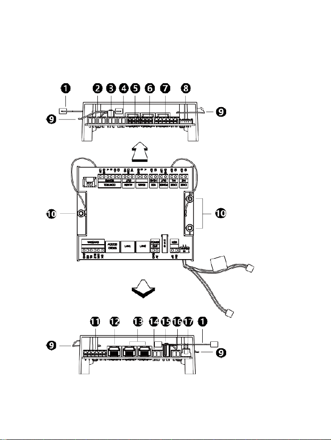
Sub Control Board
1.
Motor
interface
2. With access control board: Connects to the sub access control board’s RS485
interface
Without access control board: Connects to the verification terminal’s RS485
interface
Pinout (from left to right):
IO–,
IO+,
RS485B,
RS485A,
GND,
12V
3.
Access
indicator
light
interface
4.
Supercapacitor
interface
(reserved)
5.
Fan
interface
(reserved)
6. Control board bridging network
cable interface
7.
Bridging
power
interface
8.
Upper
light
curtain
interface
9.
Lower
light
curtain
interface
14
2.1.3
Access Control Board
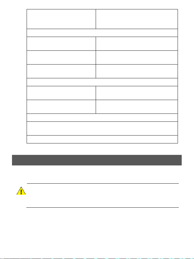
Access control boards include the main access control board and the sub access
control board.
Compared to the sub access control board, the main access control board has two
additional antennas. The rest interfaces are the same.
15
1.
Tamper
prevention
switch
wire
2. Event input interface: connects to an
external device such as button, smoke
detector, etc.
3.
12V
power
output
interface:
provides
12V
voltage
for
external
devices
4. VER HEAD: connects to
verification terminal
5.
RS485
interface
6.
Alarm
output
interface
7. Control board interface: connects to
control board
8.
LCD
interface
(reserved)
9. Antenna: only for the main access
control board
10.
Mounting
interface:
used
to
fix
access
control
board
to
speed
gate
11. Wiegand interface: connects
to card reader
12. Access control board bridging
network cable interface
13. Network interface
14. 5V power output interface: provides
5V voltage for external devices
15.
USB
interface
1:
integrates
power
supply
and
signal
input
16. USB interface 2: phoenix terminal, separating power supply and signal input
functions
17.
TEMPER
IN:
tamper
prevention
switch
interface
3.
Device
Installation
This document uses the installation of a left pedestal, a middle pedestal, and a right
pedestal as an example.
WARNING!
During installation and maintenance, power must be completely disconnected to
prevent personal injury and equipment damage.
16
3.1
Installation
Preparation
1
Site Survey Preparation
NOTE!
The installation position parameters provided in this guide are based on the 650 mm
lane width. Please determine the actual installation positions based on the lane
width of your device. Refer to the values labeled on the packaging for the exact lane
width.
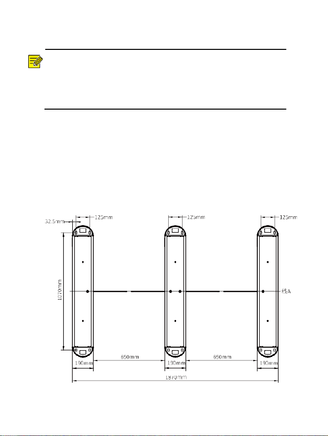
1.
At the intended installation location, draw two parallel lines along the length
direction of the gate, each 1070 mm in length and spaced 1870 mm apart. At the
center of these two parallel lines, draw a perpendicular line labeled Line A.
2.
Using Line A as the reference, determine the mounting hole positions and slot
locations according to the figure below (slots are only required at the bottom of
the gate for embedding bridging cables and network cables).
Recommended slot depth: 90–120 mm; recommended slot width: 80–100 mm.
Lane widths may vary depending on different installation scenarios; please adjust
accordingly based on actual conditions.
17
3.
Embed conduit pipes into the slotted areas. Requirements:
⚫
Outer
diameter:
40
mm
×
wall
thickness:
2
mm;
material:
PVC.
⚫ To ensure good heat dissipation and easy cable routing, the cross-sectional area
of the cables in the PVC pipe must not exceed half of the internal cross-sectional
area of the PVC pipe.
2
Installation Tools
⚫
Marker
pen
⚫ Electric drill
⚫
Network
cables
⚫ ESD wrist strap/gloves
⚫ Tape measure
⚫ Hammer
⚫ Cutter
⚫ Precision electronics
repair kit
⚫ Phillips screwdriver
NOTE!
The M12*100 expansion bolts are only suitable for concrete floors. For other types of
floors, you need to prepare the matching expansion bolts. The length of the
expansion bolt should not be less than 120mm, 150mm is recommended.
3.2
Install Barriers
NOTE!
⚫ Swing barriers must be purchased separately. Please consult your local dealer
for specific models.
⚫ The left pedestal and right pedestal each have one post, while the middle
pedestal has two posts. One barrier is installed on each post.
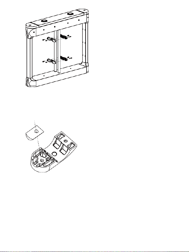
1.
Use a wrench to remove all screws securing the clamps to separate the clamps
from the posts.
18
2.
If the barriers are made of acrylic, rubber grommets must be attached to all
clamps.
Place the grommet and the clamp in the direction as illustrated, align the holes,
then press them together.
3.
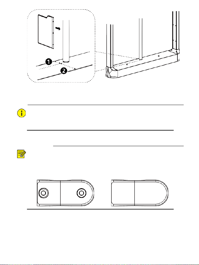
Confirm
the
orientation
and
position
of
the
barrier
relative
to
the
post.
(1)
Install the barrier on the side of the post that is closer to the pedestal edge.
(As illustrated:
①
and
②
indicate the distances from the post to the pedestal
edge; since
①
is shorter than
②
, install the barrier as indicated by the arrow.)
19
(2)
Place the perforated side of either barrier against the post. It is
recommended
that
the
barrier
be
horizontally
centered
on
the
post.
CAUTION!
If the barrier is made of acrylic, the round mounting hole must be positioned at the
bottom.
4.
Secure
the
barrier
to
the
clamps.
NOTE!
The clamp has one curved (arc-shaped) side and one approximately rectangular
side. There are two types: with holes and without holes.
Clamp with Holes Clamp without Holes
(1)
Take one clamp with holes, align the holes on its curved side with the top
mounting holes of the barrier. Then take one clamp without holes, orient its
curved side toward the barrier’s mounting holes as well, and snap it over
from the opposite side of the barrier. Secure both clamps together using
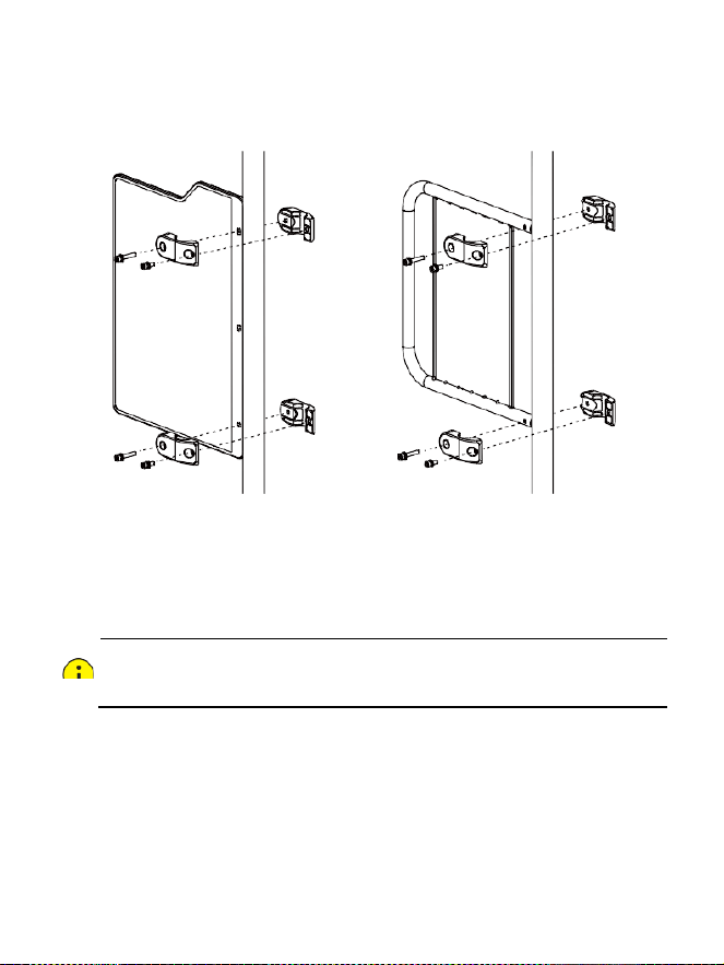
20
long screws.
(2)
Use
short
screws
to
fasten
the
other
hole
of
each
clamp.
(3)
Repeat the above two steps to secure another pair of clamps to the bottom
mounting holes of the barrier.
Acrylic
Barrier
Stainless Steel Barrier
5.
When installing a middle pedestal, refer to the previous two steps to complete
installation of another barrier.
3.3
Secure the Gate
CAUTION!
Do
not
shake
or
invert
the
device
during
installation.
1.
Drill holes at the designated mounting locations and pre-install expansion
anchors.
2.
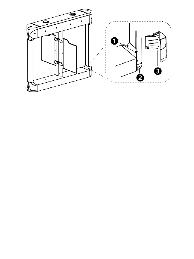
Use a Phillips screwdriver to remove the side screws (two on each side) from the
holes ① at the bottom, separating the protective cover ③ from the pedestal to
expose the mounting holes ② for the expansion bolts.
21
3.
Align the four mounting holes at the bottom of the pedestal with the pre-installed
expansion anchors and place the pedestal flat on the ground.
4.
Insert the expansion bolts into the mounting holes and hammer them in to
securely fasten the gate to the installation surface.
5.
Reattach the bottom protective cover to the housing using the side screws to
complete the mounting.
3.4
Wiring
1
Installation Preparation
1.
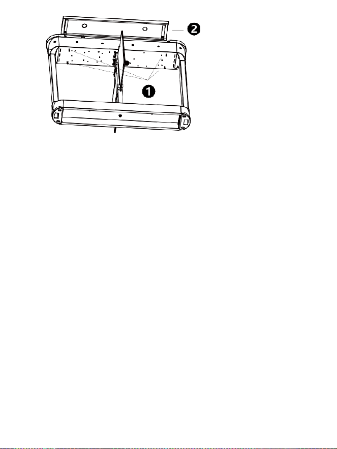
Before wiring, use the hex key to remove the four disassembly screws ① from
each gate and remove the top cover ②. After completing the wiring, reinstall the
top cover ②.
22
2.
Pre-embed the bridging cables and bridging network cables according to the
designated routing, and feed them out through the cable outlet on the side of the
gate.
2
Control Board Wiring
1.
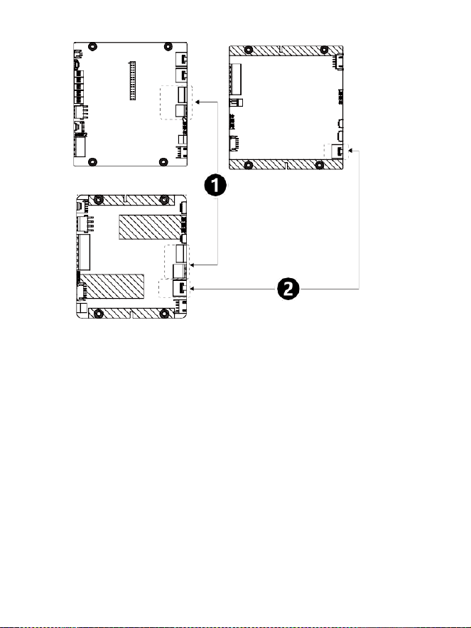
Use two bridging cables ① to connect the main control board 2 of the right
pedestal to the sub control board of the middle pedestal, and connect the main
control board 2 of the middle pedestal to the sub control board of the left
pedestal.
2.
Use two control board bridging network cables ② (white) to connect the main
control board 1 of the right pedestal to the sub control board of the middle
pedestal, and connect the main control board 1 of the middle pedestal to the sub
control board of the left pedestal.
Refer
to
the
diagram
for
the
location
of
the
interfaces.
23
Main
Control
Board
2
Main
Control
Board
1
Sub Control Board
3
Access Control Board Wiring
1.
Use two access control board bridging network cables (black) to connect the
main access control board of the right pedestal to the sub access control board
of the middle pedestal, and connect the main access control board of the middle
pedestal to the sub access control board of the left pedestal.
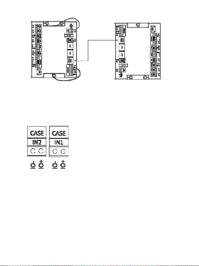
24
Main
Access
Control
Board
Sub Access Control Board
2.
(Optional) Connect external devices to the main/sub access control board of the
gate as required by the site conditions.
⚫
Event
input
devices:
for
example,
push
button,
smoke
detector,
etc.
Connect the device cables to the CASE IN1/CASE IN2 interface on the
corresponding access control board.
⚫ Connect the verification terminal (the illustration uses the main access control
board as an example; the same applies to the sub access control board).
(1)
Connect one end of the adapter cable ④ to the VER HEAD interface on the
access control board, and the other end to the IO+ and IO– terminals ② on
the verification terminal.
(2)
Connect
the
round
plug
end
of
the
extension
cable
③
to
the
power
interface
① of the verification terminal, and connect the 2-pin end to the 12V power
output interface ⑤ on the access control board.
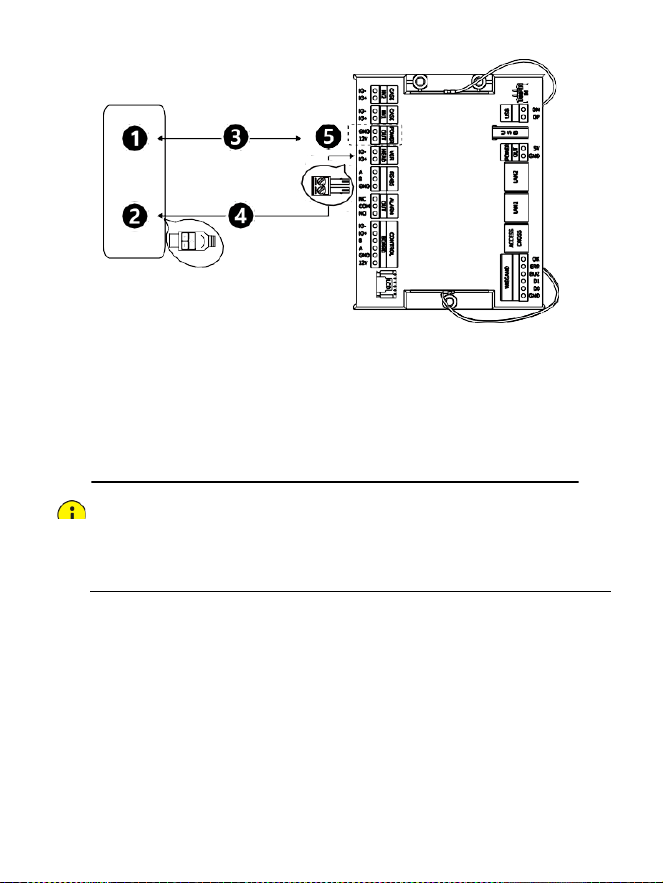
25
Verification
Terminal
Access
Control
Board
⚫ Other external devices: Connect according to your requirements. For detailed
interface descriptions, please refer to 2.1.3 Access Control Board.
4
Circuit Breaker & Ground Wiring
Both the right pedestal and the middle pedestal must have their circuit breaker
cables and ground wires connected.
CAUTION!
⚫
The input
voltage
must
be
stable
and
support
either AC 110V
or AC 220V
at
50Hz.
⚫
When
wiring,
connect
L
to
L
and
N
to
N—do
not
reverse
the
connections.
⚫ Ensure no bare wire ends are exposed; all connection points must be properly
insulated with secure insulation wrapping.
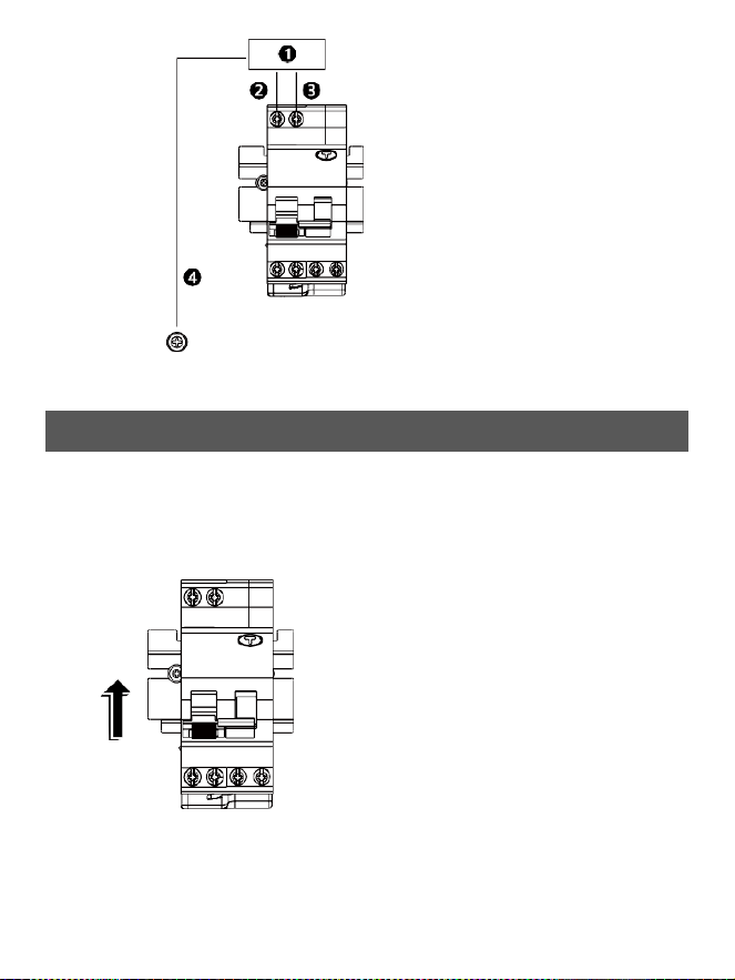
26
①
:
System
power
input
②
:
Live
wire
(L)
③
:
Neutral
wire
(N)
④
:
Ground
wire
(PE)
4.
Startup
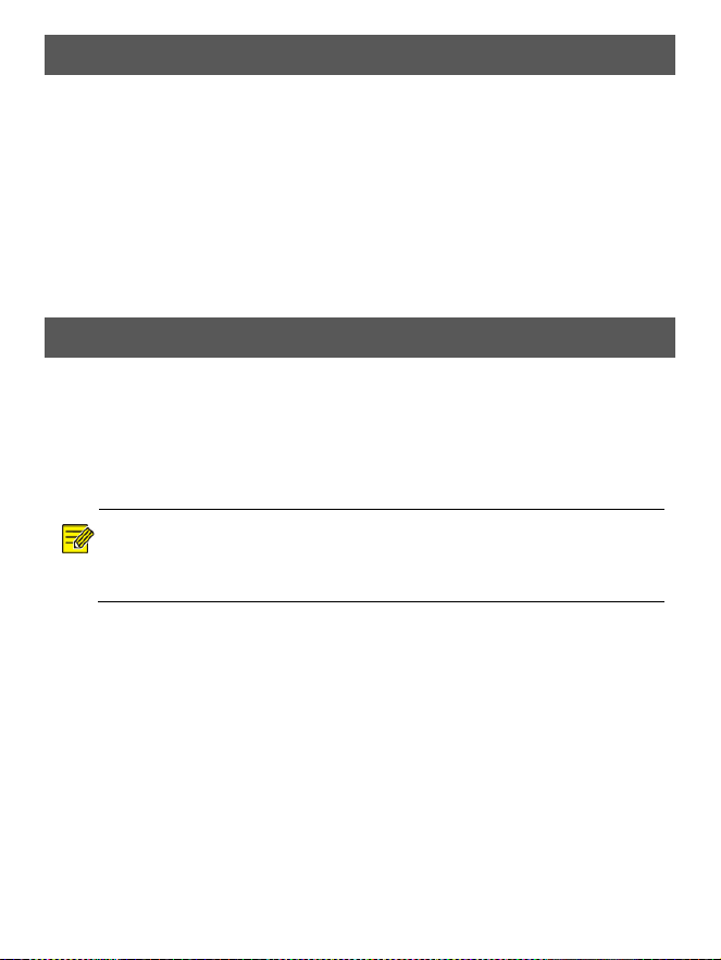
1.
After completing installation and wiring, power on the gate and toggle the circuit
breaker in the direction shown in the diagram.
The barriers will open and close once, the access indicator light will turn green,
and the buzzer will sound.
2.
Install
the
top
cover
of
the
gate
and
securely
tighten
it
with
the
key.
27
5.
Web
Login
Default IP address:
192.168.1.13
Default
username/password:
admin / 123456
Note:
For security, please set a strong password of at least
nine characters including uppercase and lowercase
letters, digits, and special characters. You are strongly
recommended to regularly change the device
password and keep it secure to ensure that only
authorized users can log in.
6.
Remote Control Operations
6.1
Remote Control Pairing
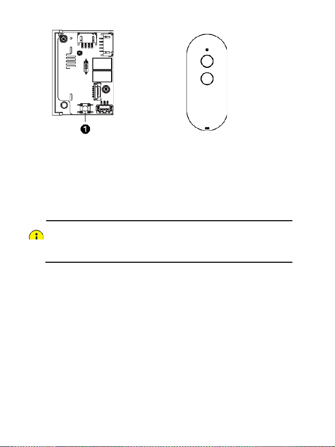
Before using the remote control, it must be paired with the receiver. One remote
control can be paired with up to 32 receivers.
1.
Press and hold the Learn button ① on the receiver. Release the button after the
receiver’s
indicator
light
flashes
once—entering
pairing
mode.
NOTE!
If multiple receivers are simultaneously in pairing mode, a single remote control can
pair with all of them at the same time.
2.
Press and hold both buttons on the remote control simultaneously. When the
receiver’s indicator light rapidly flashes 5 times, it means pairing is complete and
the receiver exits the pairing mode.
3.
To
pair
additional
remote
controls
or
receivers,
repeat
steps
1
and
2.
28
Receiver
Remote
Control
6.2
Restore Factory Defaults
Press and hold the Learn button on the receiver until the indicator light flashes
rapidly twice, then release the button. This indicates that the receiver has been
restored to factory settings and all previously stored pairing information has been
deleted. Previously paired remote controls will no longer function.
CAUTION!
If the remote control and receiver were pre-paired before shipment, do not restore
factory
defaults.