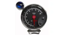
3-3/8" TACHOMETERS
INSTALLATION INSTRUCTIONS
GENERAL INFORMATION
These tachometers are designed for 12-volt negative
(-) ground 4-cycle engines. As sold they are compatible
with most distributor and distributorless ignition systems.
HARDWARE KIT CONTENTS
Dash Mount Bracket...................................................1 ea
Column Mount Bracket...............................................1 ea
Chrome Cup................................................................1 ea
Adjustable Clamp........................................................1 ea
Installation Kit .............................................................1 ea
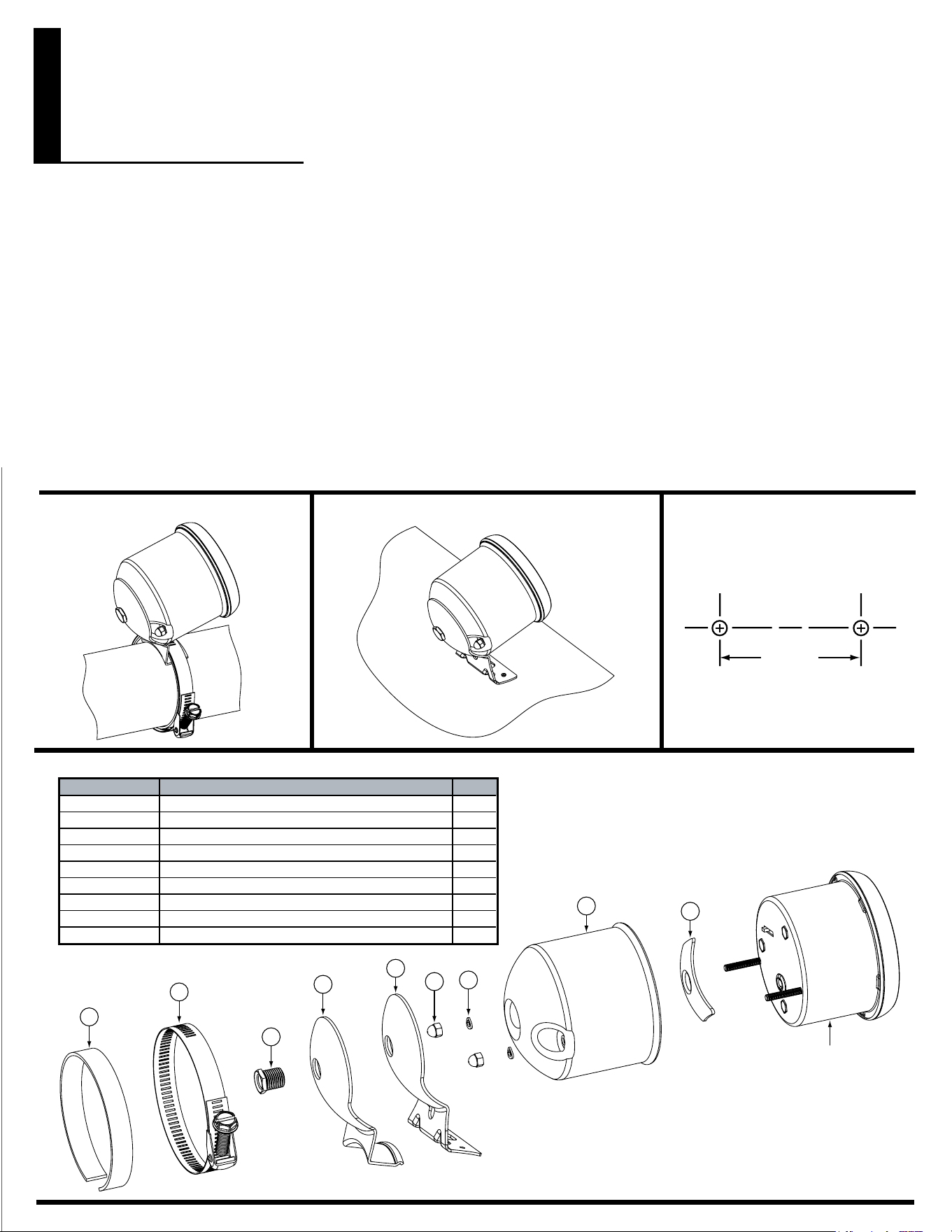
STEERING COLUMN MOUNTING INSTRUMENT PANEL MOUNTING PANEL LAYOUT
2-1/4”
9
8
3
5
4
7
1
2
6
TA CH
ITEM NO.DESCRIPTION
QTY.
1 1
2 1
3 1
4 1
5 1
6 2
7 2
8 1
9 1
CUP
FEMALE NUT
MALE NUT
MOUNTING BRACKET
COLUMN BRACKET
#8 LOCK WASHER
#8-32ACORN NUT
ADJUSTABLE CLAMP
RUBBERSTRIP
CAUTION
Please read this instruction manual and review the
installation procedures carefully before attempting the
installation of your tachometer.
SAFETY GUIDELINES
To prevent accidents that could result in serious injury and/
or damage to your vehicle or tachometer, carefully follow
these safety rules and test procedures.
• Wear safety goggles when working on your vehicle.
• Always operate vehicle in a
well-ventilated area. If vehicle is in an enclosed area,
exhaust should be routed directly to the outside via
leakproof exhaust hose.
• Make sure that your vehicle is in Park or Neutral, and
thattheparkingbrakeisrmlyset.
• Avoid contact with hot surfaces such as exhaust
manifoldsandpipes,mufers(catalyticconverters),
radiator and hoses.
FUNCTIONAL QUICK CHECK
It is suggested that the tachometer be electrically
connected to the vehicle, (using alligator clip leads or
other suitable means) following the steps below, and an
electrical functional check of the tachometer be made,
prior to making a permanent installation.
Startthevehicle’sengine.Conrmtheoperationofthe
tachometer. Disconnect the tachometer.
INSTALLING MOUNT BRACKET
Your tachometer is designed to be mounted on any
at or curved surface, or on the steering column
using the clamp kit.
Steering Column Mounting
1. Assemble steering column bracket (5) and cup (1)
using male nut (3) and female nut (2). Tighten male
nut only enough to still allow cup to be positioned to
proper angle.
2. Wrap rubber strip (9) around steering column.
3. Place assembled cup and column bracket on rubber
strip and secure to steering column with adjustable
clamp (8).
Instrument Panel Mounting
1. Select best possible mounting location for good vis-
ibility from a normal driving position.
2. Mounting bracket (4) can be used for a marking or
drill template.
3. Drill two 3/16” holes for #8 screws, lock washer and
nuts or two 5/32” holes for #8 self-tapping screws.
This picture is not to scale!
FULL ONE (1) YEAR WARRANTY
Bosch Automotive Service Solutions, 3000 Apollo Drive, Brook Park,
Ohio, 44142, warrants to the user that this unit will be free from defects
in materials and workmanship for a period of one (1) year from the date
of original purchase.
Any unit that fails within this period will be repaired or replaced at Bosch's
option and without charge when returned to the Factory. Bosch requests
that a copy of the original, dated sales receipt be returned with the unit to
determine if the warranty period is still in effect.
This warranty does not apply to damages caused by accident, alterations, or
improper or unreasonable use. Expendable items, such as batteries, fuses,
lampbulbs,ashtubesarealsoexcludedfromthiswarranty.
BOSCH AUTOMOTIVE SERVICE SOLUTIONS DISCLAIMS ANY LIABIL-
ITY FOR INCIDENTAL OR CONSEQUENTIAL DAMAGES FOR BREACH
OF ANY WRITTEN WARRANTY ON THE UNIT. Some states do not allow
the disclaimer of liability for incidental or consequential damages, so the
abovedisclai mermayormaynotapplytoyou.Th iswarrantygivesspecic
legal rights, and you may also have rights, which vary from state to state.
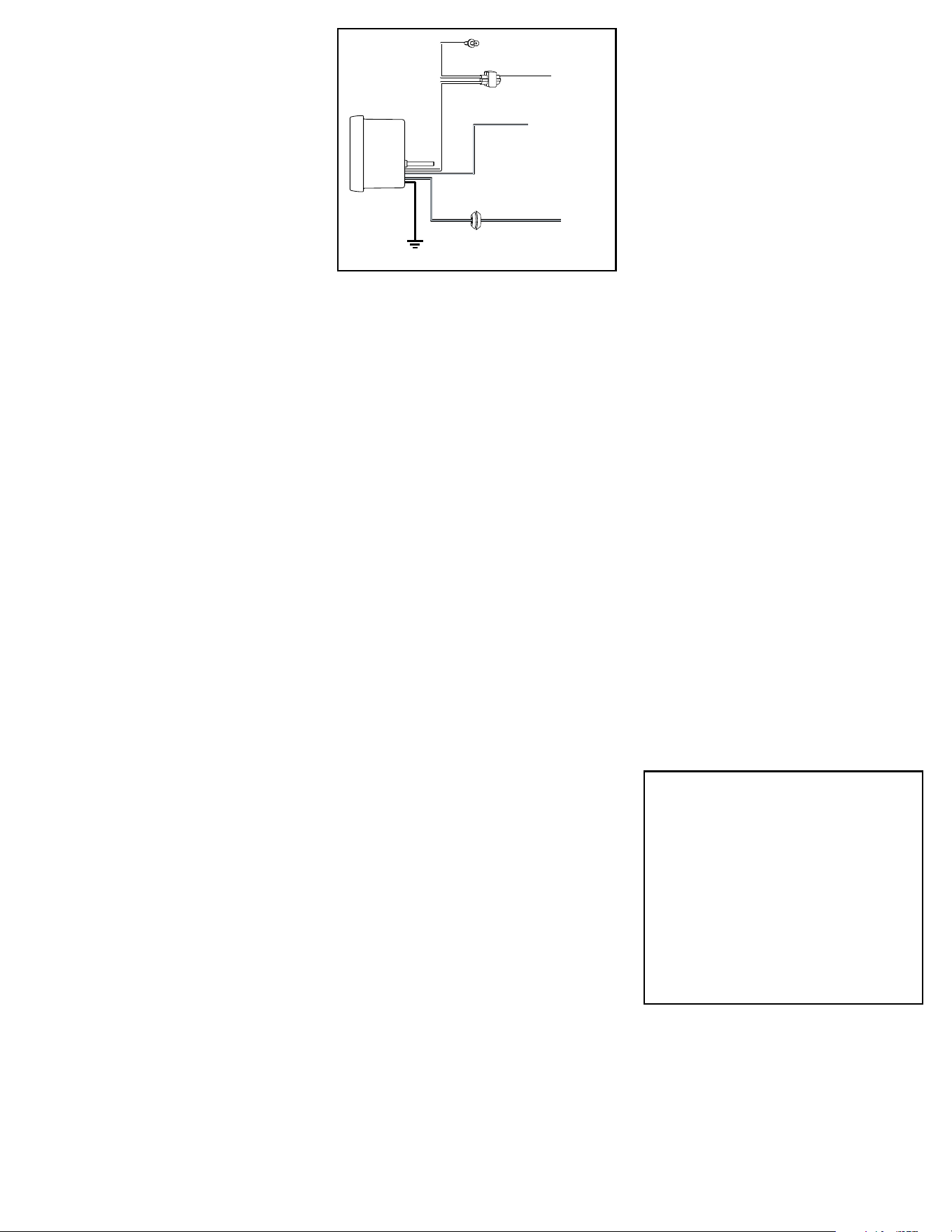
SWITCHED
+12V
SEE SIGNAL
POST CONNECTION
WIRE
SPLICE
TO DIMMER
SWITCH
LIGHT
WIRE
LAMP INSTRUMENT
GROMMET
WIRE
TO GND
GND
WIRE
SIGNAL
WIRE
+12V
ELECTRICAL CONNECTIONS
CAUTION
For your own personal safety, and to prevent possible
damage to the electrical system of your vehicle during
the installation, disconnect the negative (-) battery cable.
Reconnect this cable after installation is complete. Do
not route wires along or against sharp edges, hot engine
surfaces, or near spark plug wires. If needed, drill a 3/8”
holeintherewallforthegrommet(included).
1. Attach wires to tachometer as required.
NOTE: Use # 18 or # 20 AWG stranded automotive
primary wire.
2. Thread wires through female nut (2), cup (1), bracket
(4 or 5) and male nut (3). Note: At this point, items 1,
2, 3 and 4 or 5 should have been preassembled.
3. Leave tachometer out of the cup for now.
SIGNAL POST CONNECTION AND CYLINDER
SELECTION
The Cylinder Selector Switch is located on the back of the
tachometer. The factory setting is 8-cylinders. Change
the setting if necessary.
The 4, 6, 8, and 10-cylinder settings are most common
for all distributor equipped engines and Distributorless
Ignition Systems (DIS) with a tachometer output lead.
The 2-cylinder setting is designed for 2-cylinder engines and
DIS systems without a tachometer output lead that allow
access to the driver wires from the vehicle computer
to the ignition module.
The 1-cylinder setting is used with single cylinder engine
vehicles.
DISTRIBUTOR EQUIPPED ENGINES
Connect the SIGNAL tachometer post to the negative
(-) side of the ignition coil. This terminal may be referred
to as the TACH, TACH TEST, DEC, or ECU terminal.
Set the Cylinder Selection switch on the back of the
tachometer to match the number of cylinders in the
engine.
DISTRIBUTORLESS IGNITION SYSTEM EQUIPPED
ENGINES WITH A TACHOMETER OUTPUT LEAD
Connect the SIGNAL tachometer post to the vehicle‘s
tachometer output lead.
Set the Cylinder Selection switch on the back of the
tachometer to match the number of cylinders in the
engine.
DISTRIBUTORLESS IGNITION SYSTEM EQUIPPED
ENGINES WITHOUT A TACHOMETER OUTPUT
LEAD
If your vehicle’s DIS ignition system does not have a
tachometer output lead but allows access to the driver
wires from the vehicle computer to the ignition module,
connect the SIGNAL tachometer post to one of the
driver wires.
Set the Cylinder Selection switch on the back of the
tachometer to the 2-cylinder position regardless of
the number of cylinders in the engine.
MULTIPLE SPARK DISCHARGE IGNITION SYSTEM
EQUIPPED ENGINES
For Multiple Spark Discharge ignition systems, connect
the SIGNAL tachometer post only to the tachometer
output terminal on the ignition module. Do NOT connect
to the ignition coil.
Set the Cylinder Selection switch on the back of
the tachometer to match the number of cylinders
in the engine.
-12V DC GROUND, +12V DC POWER, AND 12V
DC LAMP POST CONNECTIONS
ALL VEHICLE SYSTEMS
1. Connect the post labeled -12V DC GROUND to the
negative (-) battery terminal, or a clean unpainted
chassis ground using a ring terminal or other suit-
able means.
2. Connect the post labeled +12V DC POWER to any
vehicle harness wire which is energized with battery
voltage, ONLY when the ignition key is in the ON
(RUN) position, NOT OFF OR ACCESSORIES.
3. Connect the post labeled 12V DC LAMP to the
instrument panel lighting circuit that is controlled by
the instrument panel dimmer control.
Some vehicles (typically imported) wire the dimmer
control into the ground side of the instrument panel
lighting circuit, as opposed to the more conventional
“hot” or 12-volt side. In vehicles which use this circuit,
connect the 12V DC LAMP post to a circuit which is
energized by the headlamp switch.
INSTALLING TACHOMETER IN CUP
1. Place tachometer in cup. Gently pull wires out, so
they would not be jammed between the cup and
tachometer.
2. Secure tachometer in cup using #8 lock washers
(6) and #8-32 acorn nuts (7). Turn acorn nuts down
nger-tightand,withawrenchornutdriver,tightenan
additional 1/2 turn. DO NOT OVER TIGHTEN.
3. Position cup as desired and tighten male nut (3).
© 2014 Bosch Automotive Service Solutions
1-800-228-7667
0002-000-3113, Rev. B