English
If #10 screws are used, mark hole locations, and drill
holes using #18 or 11/64” drill bit.
1. Loosen both button head screws on the mounting
bracket. Now, tachometer can tilt back and forth (see
gure 3).
2. Install #10 screws (see gure 3).
3. Slide the Shift Light around the tachometer to desired
position (see gure 4).
4. Tighten both button head screws on the mounting
bracket (see gure 4).
Fig. 2
STEERING
COLUMN
Hose clamp mount
(Hose Clamp not included)
Surface mount
STEP 4
Tighten button
head screws
STEP 3
Slide Shift Light
around tachometer
Fig. 4
Fig. 3
STEP 1
Loosen button
head screws
STEP 2
Install #10 screws to
mount the tachometer
MOUNTING BASE PAD
ELECTRICAL CONNECTIONS
CAUTION
For your own personal safety, and to prevent possible
damage to the electrical system of your vehicle during
the installation, disconnect the negative (-) battery cable.
Reconnect this cable after installation is complete.
Do not route wires along or against sharp edges, hot
engine surfaces, or near spark plug wires. If needed, drill
a 3/8” hole for the grommet (included).
NOTE: If additional wire is needed, use #18 or #20 AWG
stranded automotive primary wire.
• High voltage — 30,000 to 50,000 volts — is present in
the ignition coil, distributor cap, ignition wires and
spark plugs. When handling ignition wires while the
engine is running, use insulated pliers to avoid a shock.
While not lethal, a shock may cause you to jerk
involuntarily and hurt yourself.
• Never crawl under vehicle or run engine while vehicle
is on a jack.
CYLINDER SELECTION
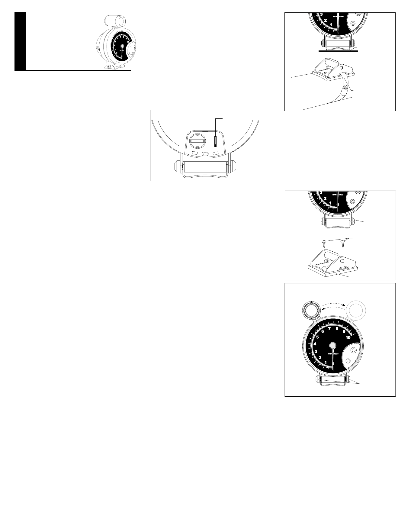
Check the cylinder setting before installation. The
Cylinder Selector Switch is located on the back of the
tachometer, behind the door (see gure 1). The Factory
Setting is 8 Cylinders. Change the setting if necessary.
CYLINDER
SELECTION
SWITCH
Fig. 1
4
2
CYL.
8
6
DISTRIBUTOR EQUIPPED ENGINES
Set the switch to match the number of cylinders in the
engine.
DISTRIBUTORLESS IGNITION SYSTEM
EQUIPPED ENGINES
The tachometer-ignition connection for some 4 Cylinder
and 6 Cylinder DIS (Distributorless Ignition System)
engines requires that you use the 2 Cylinder setting.
Depending on which type of system you have, set the
switch as follows:
If your vehicle’s DIS ignition system has a tachometer
output lead set the switch to the 4 Cylinder position for the
4 cylinder engines and to the 6 Cylinder position for the
6 cylinder engines. When connecting tachometer wires
(see ELECTRICAL CONNECTIONS), connect the
tachometer GREEN wire to the vehicle’s tachometer
output lead.
If your vehicle’s DIS ignition system does not have a
tachometer output lead but allows access to the driver
wires from the vehicle computer to the ignition module,
set the switch to the 2 Cylinder position regardless of the
number of cylinders in the engine. When connecting
tachometer wires (see ELECTRICAL CONNECTIONS),
connect the tachometer GREEN wire to either of the
driver wires.
FUNCTIONAL QUICK CHECK
It is suggested that the tachometer be electrically
connected to the vehicle, (using alligator clip leads or
other suitable means) following the steps below, and an
electrical functional check of the tachometer be made,
prior to making a permanent installation.
Start the vehicle’s engine. Conrm the operation of the
tachometer. Disconnect tachometer.
MOUNTING THE TACHOMETER
Your tachometer is designed to be mounted on any
at or curved surface, or on the steering column (see
gure 2).
5” TACHOMETER
INSTALLATION INSTRUCTIONS
GENERAL INFORMATION
Please read this instruction manual and review the
installation procedures carefully before attempting the
installation of your tachometer.
CAUTION
This unit is designed for use on 12-volt negative (-) ground
4-cycle automotive type engines. The tachometer is
compatible with most distributor and distributorless
ignition systems.
PACKAGE CONTENTS
Contains Installation Hardware Kit consisting of:
Tachometer Mounting Base Pad....................................1 ea
1/4” Quick Connect Receptacle......................................1 ea
Grommet...........................................................................1 ea
Hex Key Wrench..............................................................1 ea
Wire Splices.....................................................................2 ea
Ring Terminals.................................................................2 ea
#10 X 5/8” Self-tapping Screw........................................2 ea
SAFETY GUIDELINES
To prevent accidents that could result in serious injury and/
or damage to your vehicle or tachometer, carefully follow
these safety rules and test procedures.
Fire Extinguisher
• Never work on your vehicle without having a suitable
re extinguisher handy. A 5-lb or larger CO2 or dry
chemical unit specied for gasoline/chemical/electrical
res is recommended.
Safety Goggles
• We recommend wearing safety goggles when working
on your vehicle, to protect your eyes from battery acid,
g a s o l i n e, and dust and d i r t y i n g o f f m ov i n g engine
parts.
• Be very careful not to get your hands, hair or clothes
near any moving parts such as fan blades, belts and
pulleys or throttle and transmission linkages. Never wear
neckties or loose clothing when working on your
vehicle.
• Never wear wrist watches, rings or other jewelry when
working on your vehicle. You’ll avoid the possibility
of catching on moving parts or causing an electrical
short circuit which could shock or burn you.
• The carbon monoxide in exhaust gas is highly toxic. To
avoid asphyxiation, always operate vehicle in a
well-ventilated area. If vehicle is in an enclosed area,
exhaust should be routed directly to the outside via
leakproof exhaust hose.
• Make sure that your vehicle is in Park or Neutral, and
that the parking brake is rmly set.
• Avoid contact with hot surfaces such as exhaust
manifolds and pipes, mufers (catalytic converters),
radiator and hoses.
• Never smoke while working on your vehicle. Gasoline
vapor is highly ammable, and the gas formed in a
charging battery is explosive.
• Do not lay tools or equipment on the battery.
Accidentally grounding the “HOT” battery terminal
can shock or burn you and damage wiring,the battery
or your tools and testers. Be careful of contact with
battery acid. It can burn holes in your clothing and burn
your skin or eyes.
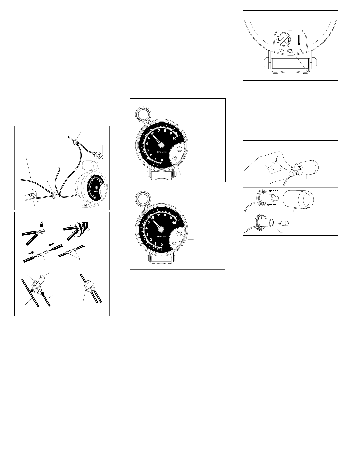
Fig. 10
STEP 1
Press and turn coin
counter clockwise to
unlock rear cap
STEP 3
Pull lamp
straight out
STEP 2
Pull rear
cap out
LAMP SOCKET
LAMP
Fig. 9
BACKLIGHTING
LAMP SOCKET
4
2
CYL.
8
6
FULL ONE (1) YEAR WARRANTY
Bosch Automotive Service Solutions, 3000 Apollo Drive, Brook Park,
Ohio 44142, warrants to the user that this unit will be free from defects in
materials and workmanship for a period of one (1) year from the date of
original purchase.
Any unit that fails within this period will be repaired or replaced at Bosch’s
option and without charge when returned to the factory. Bosch requests
that a copy of the original, dated sales receipt be returned with the unit to
determine if the warranty period is still in effect.
This warranty does not apply to damages caused by accident, alterations, or
improper or unreasonable use. Expendable items, such as batteries, fuses,
lamp bulbs, ash tubes are also excluded from this warranty.
B O S C H A U T O M OT I V E S ER V I C E S O LU TI O N S D I SC L A I M S A N Y L I A BI L IT Y
FOR INCIDENTAL OR CONSEQUENTIAL DAMAGES FOR BREACH OF
ANY WRITTEN WARRANTY ON THE UNIT. Some states do not allow
the disclaimer of liability for incidental or consequential damages, so the
above disc laimer may or may not a pply to you. This war r ant y gives sp ecic
legal rights, and you may also have rights, which vary from state to state.
SHIFT LIGHT LAMP REPLACEMENT
The External Shift Light also uses a wedge base lamp
for illumination.
To replace the Shift Light lamp, follow steps to open
the shift light (see gure 10). Remove the lamp from
its socket by pulling it straight out. Replace the lamp
with a #168 automotive lamp. If light is too bright,
replace with a lamp of less intensity such as #194 or #161.
Reassemble the shift light by reversing the steps.
BLACK, RED, AND WHITE WIRE CONNECTIONS
– ALL SYSTEMS
1. Connect the BLACK wire to the negative (-) battery
terminal, or a clean unpainted chassis ground using a
ring terminal or other suitable means (see gure 5.)
Make the following connections with wire splices, or
by an alternative method if desired (see gure 6.)
2. Connect the RED wire to any vehicle harness wire
which is energized with battery voltage, ONLY when the
ignition key is in the ON (RUN) position, NOT OFF OR
ACCESSORIES (see gure 5.)
3. Connect the WHITE wire to the instrument panel
lighting circuit that is controlled by the instrument panel
dimmer control (see gure 5.)
Some vehicles (typically imported) wire the dimmer control
into the ground side of the instrument panel lighting
circuit, as opposed to the more conventional “hot” or 12-volt
side. In vehicles which use this circuit, connect the WHITE
wire to a circuit which is energized by the headlamp switch.
VEHICLE
HARNESS WIRE
PIERCING
CLIP
Fig. 6
CONNECTOR
WIRE SPLICE
LIP UNLOCKED
TACHOMETER
WIRE
WIRE SPLICE
LOCKED
ELECTRICAL
TAPE
CRIMP ENDS
SOLDER
Fig. 5
RED WIRE
TO BATTERY
VOLTAGE
GROMMET
RING
TERMINAL
WHITE
WIRE
BLACK
WIRE TO GROUND
SEE THE GREEN
WIRE CONNECTION
SECTION OF
THIS MANUAL
INSTRUMENT
LAMP
WIRE
SPLICE
TO DIMMER
SWITCH
GREEN WIRE CONNECTION
The GREEN wire provides the tachometer with the engine
RPM (speed) signal.
DISTRIBUTOR EQUIPPED ENGINES
Connect the GREEN wire to the negative (-) side of the
ignition coil. This terminal may also be referred to as the
TACH, TACH TEST, DEC, or ECU terminal.
DISTRIBUTORLESS IGNITION SYSTEM EQUIPPED
ENGINES
If your vehicle’s DIS ignition system has a tachometer
output lead set the switch to the 4 Cylinder position for the
4 cylinder engines and to the 6 Cylinder position for the
6 cylinder engines. Connect the tachometer GREEN wire
to the vehicle’s tachometer output lead.
If your vehicle’s DIS ignition system does not have a
tachometer output lead but allows access to the driver
wires from the vehicle computer to the ignition module,
set the switch to the 2 Cylinder position regardless of the
number of cylinders in the engine. Connect the tachometer
GREEN wire to either of the driver wires.
MULTIPLE SPARK DISCHARGE IGNITION
SYSTEM EQUIPPED ENGINES
For Multiple Spark Discharge ignition systems, connect
the GREEN wire only to the tachometer output terminal on
the ignition module. Do NOT connect to the ignition coil.
SHIFT LIGHT RPM TRIP POINT SET-UP
Some possible uses for the Shift Light are:
• Engine RED LINE (maximum safe operating speed of
the engine)
• Engine maximum torque RPM (for maximum
performance shifting) and desired shift speed.
NOTE
:
You will need both hands free to set the
tachometer (see gures 7 and 8).
Fig. 8
1. Push and hold
lower knob
To set Shift Light
trip point
2. At the same time
push and rotate
upper knob
Fig. 7
To view Shift Light trip point
Push and hold lower knob
1. Turn the ignition key to the ON position. The engine does
not have to be running.
2. Push and keep the LOWER knob depressed.
3. Push in and rotate the UPPER control knob until the
tachometer pointer indicates the RPM trip point at
which the Shift Light should turn ON.
4. Release both the LOWER knob and the UPPER
control knob.
Note:
If at any time the tach pointer appears to freeze
beyond the 10,000 RPM marker: 1) Turn on the ignition
2) Push and hold both knobs 3) Turn the UPPER knob
fully clockwise and then return to the desired trip point.
BACKLIGHTING LAMP
SUBSTITUTION OR REPLACEMENT
The tachometer is supplied with a #168 wedge base
lamp. If the light is too bright, replace with a lamp of less
intensity such as a #194 or #161.
The lamp socket is located in the rear of the housing
of the tachometer (see gure 9). To remove the lamp, gently
grasp the black lamp socket (use pliers if necessary)
and twist it counterclockwise approximately 1/8 turn
until it stops. Pull the socket with lamp straight out of the
tachometer housing. Remove the lamp from its socket
by pulling it straight out. Replace the lamp. Reinstall the
socketed lamp by rotating it against the tachometer’s
internal PC board until it drops into place, and then rotate
it approximately 1/8 turn clockwise until it reaches its
mechanical stop.
© 2014 Bosch Automotive Service Solutions
1-800-228-7667
0002-000-2861, Rev. B