21
3 A
A wireless intercom specialized for OUTDOOR ACTIVITIES,
Designed with advanced technology to be versatile and user-friendly
Model ; GCX-2.4
ver.60608MST
Maytel Co., Ltd
USER'S MANUAL FOR
GrandCom-X

TABLE OF CONTENTS
page 1GCX-2.4 User’s Manual
1. General Information
2. Controls and Indicators
3. Tech menu to Select Operational Modes
3.1 Standard Mode [10U]
3.2 Repeater Mode [STA]
3.3 Minimize Wi-Fi Interference Mode [6U]
4. How to Use
4.1 Power On/O
4.2 Volume Up/Down
4.3 Group Selection
4.4 ID Selection
4.5 Side Tone (Self-Voice Feedback) Level Selection
4.6 Microphone Sensitivity Level Selection
4.7 Security Code Selection
4.8 Channel Selection
4.9 Battery Replacement
5. Technical Specication
6. Declaration of Conformity
7. Warranty
8. Waste Disposal
1.1 Introduction
1.2 Main Features
1.3 Standard Packaging Components
2 - 4
2
3
4
5 - 6
7 - 10
8
9
10
11 -16
11
11
11
12
13
13
14
14 - 15
16
17
18
18
18

1. General Information
page 2
GCX-2.4 User’s Manual
1.1 Introduction
GrandCom-X is an ultra-compact wireless intercom designed with
cutting-edge technology that allows up to 10 people to communicate
without any central stations or hubs.
With its user-friendly features and reliable performance, it will support
your group’s needs for all outdoor activities, including sports referees,
safety guards, construction sites, reghting, helicopter rescue teams,
road maintenance, hazardous materials production plants, miners,
broadcast cameramen, skiers, rock climbers, hang gliders, and more.
In addition, it oers three selectable operating modes that can be easily
congured on-site, allowing users to optimize performance according
to specic working conditions and environments.

page 3
GCX-2.4 User’s Manual
Completely secured conversation with individual PIN encryption settings
for each group directly set by the user
Eectively suppresses peak noise levels above 115dBm, minimizing
stress and fatigue on the user’s hearing
1.2 Main Features
Realize 9 xed users + Any one out of unlimited participants directly
talking together with hands-free simultaneously while rest members
are listening
Support 3 professional operating modes and directly select the optimized
mode according to the environment in the eld to ensure the maximum
talk performance
Supports allocation of up to three sub-channels belonging to a single
communication group, allowing the master to make separate calls for
each channel or to make calls to all channel members within the group
In 6U mode, GCX is designed to enable communication even in areas
with full-band Wi-Fi interference by applying the most advanced
proprietary protocol
Clear sound quality and loud enough audio output through application
of optimized compandor technology
Optimized long talk range through support for three professional
operational modes that can be directly selected in the eld according
to the user's environment
IP54 water resistance and excellent performance of internal antenna
allows for outdoor activities without snag hazards

page 4
GCX-2.4 User’s Manual
GCX-2.4
BC-01GC
HSB-02G
UC-01C
Battery Cover Opener
User’s Manual
Carrying Bag
1 unit
1 ea
1 ea
1 ea
1 ea
1 ea
1 ea
1.3 Standard Packaging Components
; GrandCom-X
; Belt Clip Cradle
; Mono Pad Headset Boom Microphone
; USB Charging Cable Type-C
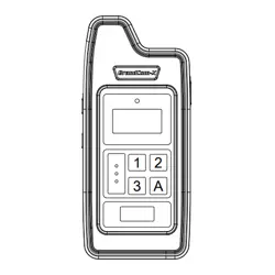
2. Controls and Indicators
page 5
GCX-2.4 User’s Manual
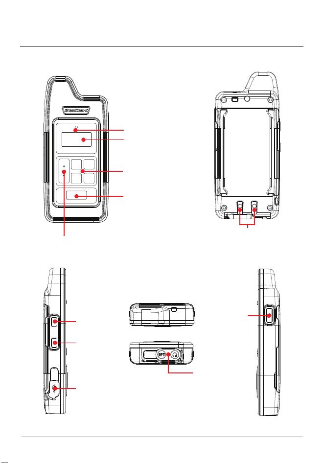
Down
Button
Up
Button
Power
Button
21
3 A
Talk
Button
Mode
Button
OLED Display
LED Indicator
Channel
Button
Headset Jack
USB Jack

page 6
GCX-2.4 User’s Manual
Power Button
Press and hold the “Power” button for 3 seconds to turn the device
power On/O
Mode Button
Select Group number, ID number, Side Tone, Microphone sensitivity
level, Operation mode selection and Security Code selection
Down Button
Decrease volume level, Group number, and ID number etc. in each mode
Talk Button
Mute On/O
Up Button
Increase volume level, Group number, and ID number etc. in each mode
Channel Button
Select 3 channels within a group
Indicate communication status / battery status / group / ID / mute status
/ selected channel / volume status / operating mode display
OLED Display
LED Indicator
LED turns on while charging the device and in range of communication
status
Headset Jack
3.5mm 2 plug headset contact
USB Jack
USB Type-C port for rmware upgrade and battery recharge

< Tech menu >
Mode of operation
STA 10U 06U
When the power is On, press and hold the “Mode” button and the “A”
button simultaneously for 3 seconds to enter the Tech menu.
At this time, the current operational mode blinks.
Select the mode you desire to apply with the “Up/Down” buttons, and
press and hold the “Mode” button again for 3 seconds.
The power turns O, and the mode is changed.
When power is turned back On, the lately selected operational mode is
displayed at the bottom right of the display.
3. Tech menu to Select Operational Modes
page 7
GCX-2.4 User’s Manual
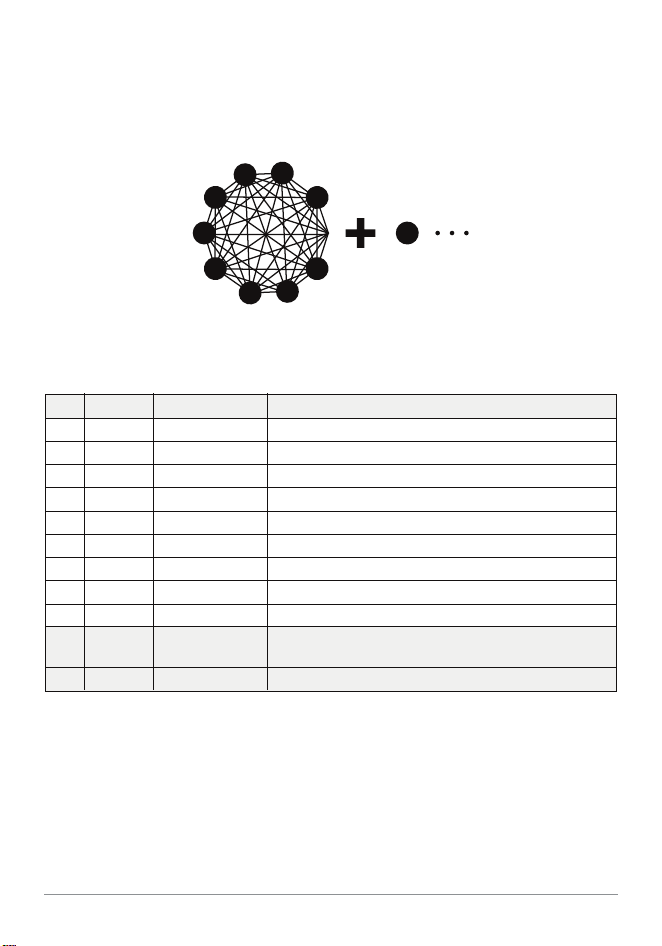
3.1 Standard Mode [10U]
This [10U] mode supports 9 xed users + any one out of the participants
talking together simultaneously.
Table 1, ID Setting for [10U] mode
ID Status Operation Description
M Master Always TX/RX
01 Slave Always TX/RX
02 Slave Always TX/RX
03 Slave Always TX/RX
04 Slave Always TX/RX
05 Slave Always TX/RX
06 Slave Always TX/RX
07 Slave Always TX/RX
08 Slave Always TX/RX
Each group must be assigned one master
Simultaneous TX and RX with other ID members
Simultaneous TX and RX with other ID members
Simultaneous TX and RX with other ID members
Simultaneous TX and RX with other ID members
Simultaneous TX and RX with other ID members
Simultaneous TX and RX with other ID members
Simultaneous TX and RX with other ID members
Simultaneous TX and RX with other ID members
L Listener Listen Only As a user who only receives, it can be selected as unlimited.
S Shared Shared TX
Whoever presses the talk button rst becomes the talker.
ID; S can be selected indenitely.
page 8
GCX-2.4 User’s Manual
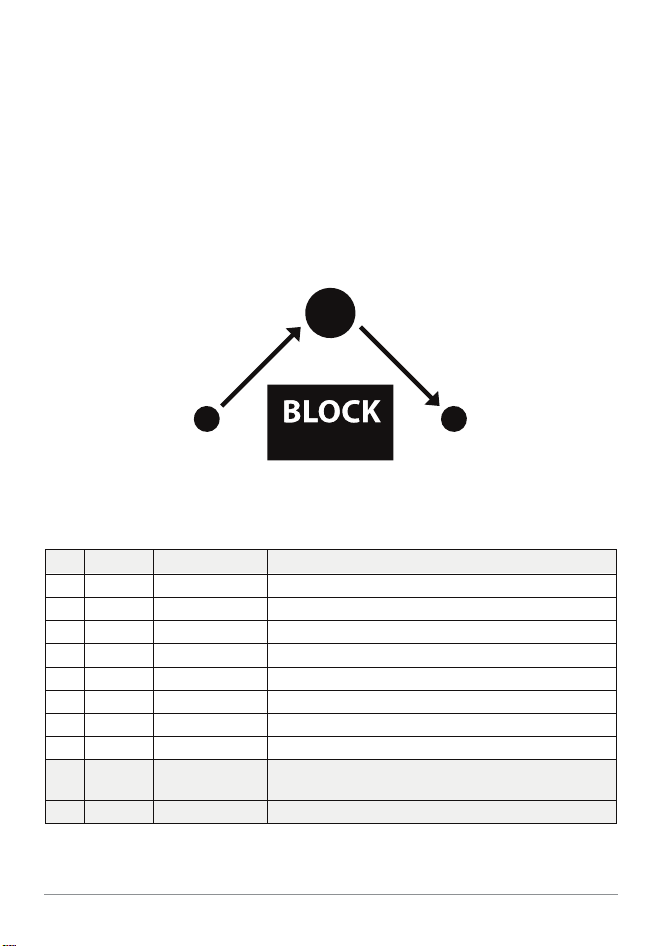
Table 2, ID Setting for [STA] mode
ID Status Operation Description
M Master Always TX/RX Each group must be assigned one master
01 Slave Always TX/RX Simultaneous TX and RX with other ID members
02 Slave Always TX/RX Simultaneous TX and RX with other ID members
03 Slave Always TX/RX Simultaneous TX and RX with other ID members
04 Slave Always TX/RX Simultaneous TX and RX with other ID members
05 Slave Always TX/RX Simultaneous TX and RX with other ID members
06 Slave Always TX/RX Simultaneous TX and RX with other ID members
07 Slave Always TX/RX Simultaneous TX and RX with other ID members
L Listener Listen Only As a user who only receives, it can be selected as unlimited.
S Shared Shared TX
Whoever presses the talk button rst becomes the talker.
ID; S can be selected indenitely.
3.2 Repeater Mode [STA]
page 9
GCX-2.4 User’s Manual
Master
This [STA] mode is an operating mode that allows all members of a group
to talk through the Master unit.
When the locations of members are obscured by barriers or other obstacles,
applying this [STA] mode can minimize the impact of such obstacles.
By installing the Master unit in the most ideal location, communication
between the remaining members will be conducted through the Master
unit, thereby minimizing the impact of such obstacles.
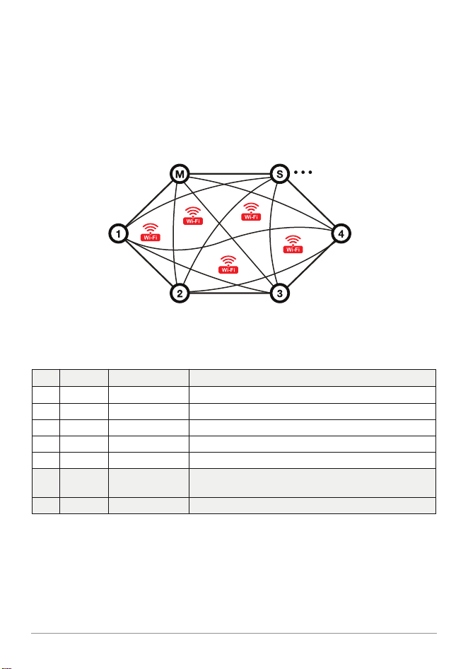
Table 3, ID Setting for [6U] mode
ID Status Operation Description
M Master Always TX/RX Each group must be assigned one master
01 Slave Always TX/RX Simultaneous TX and RX with other ID members
02 Slave Always TX/RX Simultaneous TX and RX with other ID members
03 Slave Always TX/RX Simultaneous TX and RX with other ID members
04 Slave Always TX/RX Simultaneous TX and RX with other ID members
L Listener Listen Only As a user who only receives, it can be selected as unlimited.
S Shared Shared TX
Whoever presses the talk button rst becomes the talker.
ID; S can be selected indenitely.
3.3 Minimize Wi-Fi Interference Mode [6U]
page 10
GCX-2.4 User’s Manual
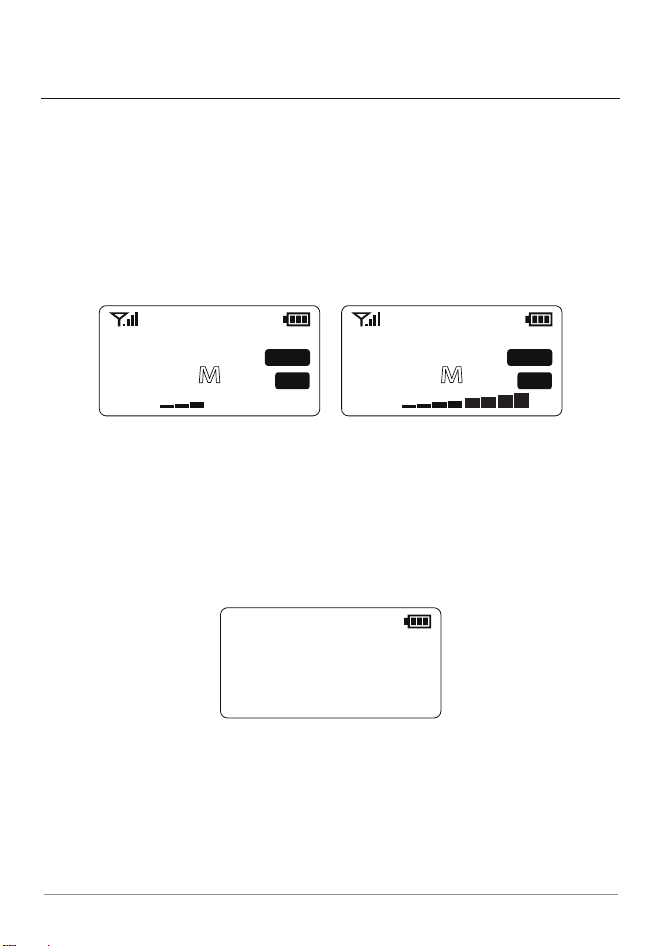
This [6U] operating mode applies its own specialized solution to maintain
communication while minimizing the inuence of Wi-Fi even in special
environments such as exhibition halls or stadiums with large crowds
where Wi-Fi is radiating in full band.
This mode supports up to 6 simultaneous talk users.
4. How to Use
page 11
GCX-2.4 User’s Manual
4.1 Power On/O
Press and hold the "Power" button for longer than 3 secs to turn the device
power On/O.
4.3 Group Selection
< Setting Mode >
1.GROUP 00
Press and hold the "Mode" button till “Setting Mode” is displayed.
Select the Group number “00”~”39” for GCX-2.4 you desire by pressing
the "▲" or "▼" button.
Long press the “Mode” button to set the Group number you selected.
All devices should have the same Group number to communicate with
each other within the group.
4.2 Volume Up/Down
Press "▲" button to control volume up and "▼" button for volume down
after turn the device power On.
It is available to adjust the volume level 0~8.
GROUP
I D
00
VOLUME 10U
TALK
CH1
M
GROUP
I D
00
VOLUME 10U
TALK
CH1
M

page 12
GCX-2.4 User’s Manual
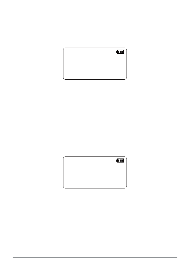
4.4 ID Selection
< Setting Mode >
2.ID M
In a group, every device needs to have each dierent ID per device from
"M", ”01” to “08”, ”S”, ”L”.
Press and hold the "Mode" button till “Setting Mode” is displayed.
Short press the “Mode” button then “ID” is displayed in “Setting Mode”.
Select each dierent ID number per device from "M",”01” to “08”, ”S”, ”L”
in a group by pressing the "▲" or "▼" button.
Long press the “Mode” button to set the ID number you selected.
The available IDs are as follows.
- 10U Mode ; "M",”01” to “08”, ”S”, ”L” (Refer to table 1)
- STA Mode ; "M",”01” to “07”, ”S”, ”L” (Refer to table 2)
- 6U Mode ; "M",”01” to “04”, ”S”, ”L” (Refer to table 3)
The ID "M" becomes a master device in a group and every group needs
to have the ID "M" device without alternative.
Other IDs except “S” and “L” serve a full hands-free talking at the same time.
The ID “S” is operated by anyone pressing “Talk” button and talk as open slot.
If you press “Talk” button while someone else among users who have ID
“S” is talking, an alert will occur and your “Talk” button will not be activated.
You need to wait for the person currently talking to release “Talk” button
and then press “Talk” button.
ID “L” is Listen Only and can’t speak.
The ID “S” and “L” can be selected indenitely.
4.5 Side Tone (Self-voice feedback) Level Selection
4.6 Microphone Sensitivity Level Selection
page 13
GCX-2.4 User’s Manual
< Setting Mode >
3.SIDE TONE 1
< Setting Mode >
4.MIC GAIN 1
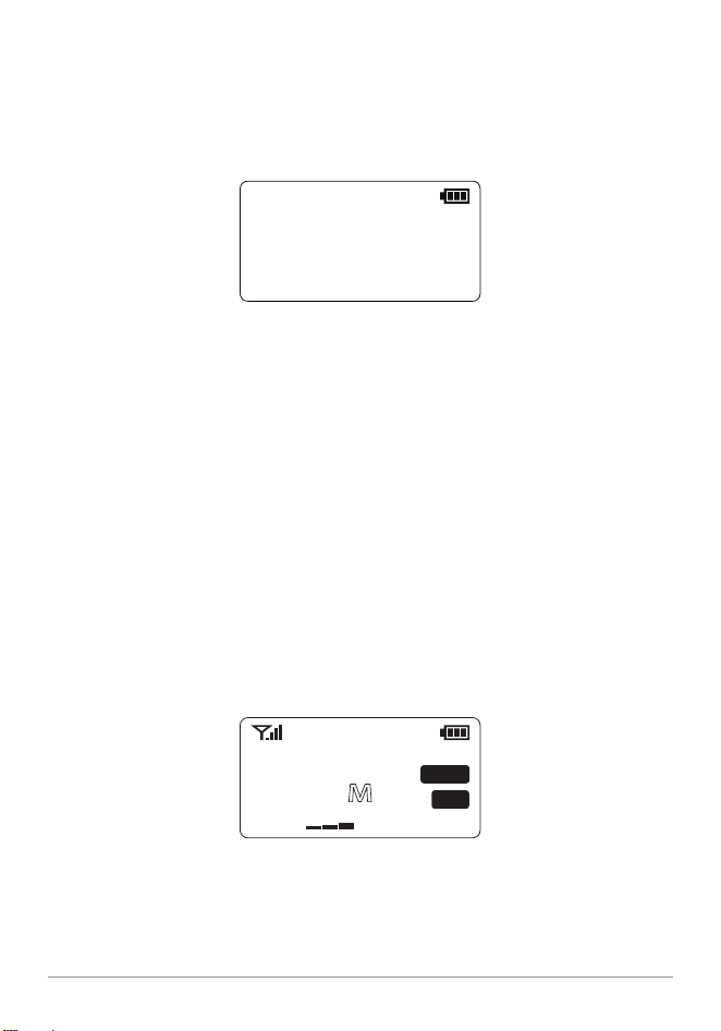
Press and hold the "Mode" button till “Setting Mode” is displayed.
Press the “Mode” button until the “SIDE TONE” menu appears, then adjust
the SIDE TONE setting.
Select the Side Tone “OFF” or “1” to ”5” by pressing the "▲" or "▼" button.
Long press the “Mode” button to set the Side Tone you selected.
Press and hold the "Mode" button till “Setting Mode” is displayed.
Press the “Mode” button until the “MIC GAIN” menu appears, then adjust
the MIC GAIN setting.
Select the Microphone Sensitivity Level “1” to ”8” by pressing the "▲" or
"▼" button.
Long press the “Mode” button to set the Microphone sensitivity level
you selected.
This feature allows you to assign desired IDs to up to three sub-channels
in one group, allowing split talks only between IDs belonging to the
corresponding channels.
It can be set separately for “CH1”, “CH2”, “CH3”, and “ALL”.
Press and hold each “Channel” button “1”, “2”, “3”, “A” on the front of the
device for 3 seconds to set the channel.
The selected channel number appears on the right side of the display.
4.7 Security Code Selection
page 14
GCX-2.4 User’s Manual
< Setting Mode >
5.SEC CODE 0000
Press and hold the "Mode" button till “Setting Mode” is displayed.
Press the “Mode” button until the “SEC CODE” menu appears, then adjust
the SEC CODE setting.
The security code consists of four digits and it is available for you to select
“0” to ”9”, “A”, “B”, “C”, “D”, “E”, “F” for each digit by pressing the "▲" or "▼"
button.
Short press “Mode” button to change the next digit after setting one.
Long press the “Mode” button to set the security code you selected.
4.8 Channel Selection
GROUP
I D
00
VOLUME 10U
TALK
CH1
M
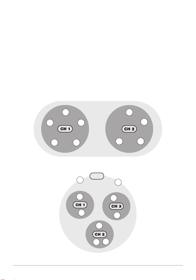
1) Example of operation by allocating to two – sub channels
2) Example of operation by allocating with three sub – channels and ALL
ID
M
ID
01
ID
04
ID
05
ID
08
ID
02
ID
03
ID
06
ID
07
page 15
GCX-2.4 User’s Manual
If a channel other than "ALL" is selected, communication is only possible
between devices on the same channel.
; CH1 can only talk to devices assigned to CH1 in the same group number.
; CH2 can only talk to devices assigned to CH2 in the same group number.
; CH3 can only talk to devices assigned to CH3 in the same group number.
; ALL can talk with all devices in the same group number.
ID
M
ID
01
ID
04
ID
08
ALL
ID
05
ID
03
ID
02
ID
07
ID
06
Channels can be freely changed at any time by pressing the desired number
for 3 seconds as needed.
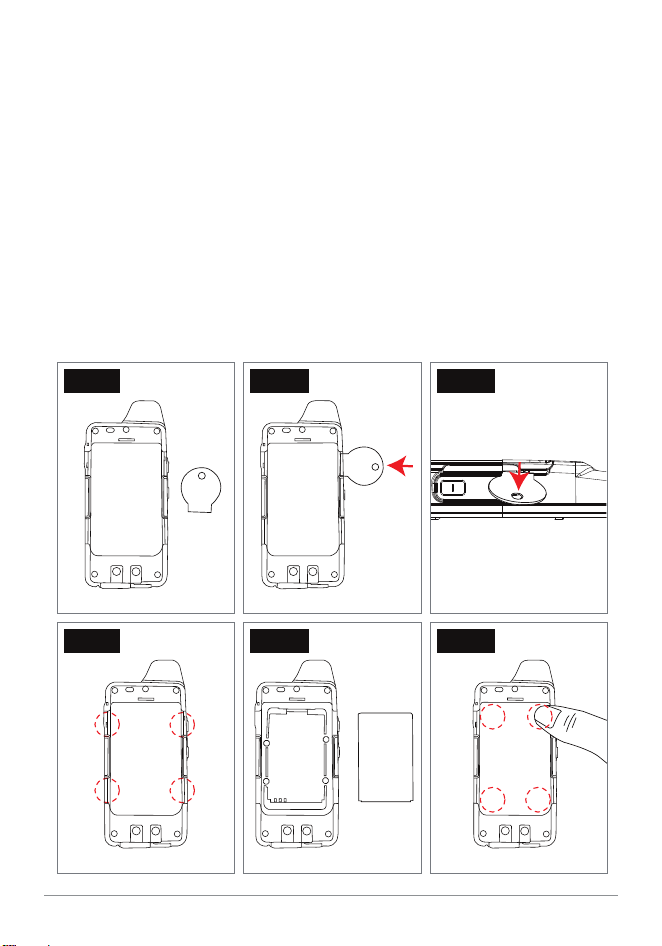
Step 1 – Prepare GrandCom-X and the Battery Cover Opener which is
included in the package box or small coin
Step 2 – Place the opener or small coin in the gaps behind the GrandCom-X
Step 3 – Push the opener or small coin down to create an opening
Step 4 – Repeat for all 4 gaps
Step 5 – Open the back cover and replace the battery
Step 6 – Close the cover and push down on all 4 corners of the back cover
4.9 Battery Replacement
page 16
GCX-2.4 User’s Manual
Battery Cover
Opener
Step 1 Step 2
Push
Step 3
Step 4
Li-ion Battery
Step 5
Step 6
Push

Dimension – Unit only 120 x 53 x 19.5mm
121.8 x 56.6 x 27.2mmDimension w/ Belt Clip Holster
121gWeight w/ Belt Clip Holster
ISM 2,407MHz - 2,476MHzRadio Frequency Type
50Hz - 4KHzFrequency Response
GFSK with FHSS; Frequency HoppingModulation
Tx Output Power
- 95dBmRx Sensitivity
16bit / 8KHzVoice CODEC
40Number of Groups
500KHzChannel Spacing
Water resistant, IP54Environmental Rating
Power Supply
Antenna
Internal Type
5. Technical Specication
page 17
GCX-2.4 User’s Manual
About 17 dBm
Li-Ion Battery @3.7V / 1,200mA

page 18
GCX-2.4 User’s Manual
6. Declaration of Conformity
MayMax hereby declares that MayMax conforms to the major characteristic
specications and other relevant specications given in the Directive
1999/5/EEC and is made after following specications;
7. Warranty
MayMax will give 12 months warranty against failure made by the
manufacturer from the date of purchase. The warranty will not cover
damage made by the user, the user opening the equipment, moist,
dirt, heat or cold. The warranty will not cover lightning/overvoltage.
Please, contact your dealer if a problem with the equipment arises.
8. Waste Disposal
Electrical and electronic products can contain materials, parts and
units that can be dangerous for the environment and human health.
Products marked with the WEEE mark (shown below), shall not be
disposed together with your normal household waste. Please
inform yourself about the local rules and disposal collection system
for electrical and electronic products. The correct disposal of your
old product will help to prevent negative consequences for the
environment and human health.
(WEEE = Waste of Electrical & Electronic Equipment)
EN 62368-1
EN 301 489-1, -17
EN 300 328
This product is compliant with the RoHS Directive 2002/95/EC.
MayMax Co., Ltd.
#416 Doosan Venture Digm, Heung An Dae-Ro, Dongan-Gu,
Anyang-Si, Gyeonggi-do, South Korea (Zip; 14059)
www.maymax.co.kr
Replaceable battery
If an equipment is provided with a replaceable battery, and if replacement by an
incorrect type could result in an explosion (for example, with some lithium batteries),
the following:
- if the battery is placed in an OPERATOR ACCESS AREA, there shall be a marking
close to the battery or a statement in both the operating and the servicing instructions;
- if the battery is placed elsewhere in the equipment, there shall be a marking close to
the battery or a statement in the servicing instructions.
This marking or statement shall include the following or similar text:
CAUTION
RISK OF EXPLOSION IF BATTERY IS REPLACED BY AN INCORRECT TYPE.
DISPOSE OF USED BATTERIES ACCORDING TO THE INSTRUCTIONS.
This product has been certified with t
he following antennas, and may only be used with the same or
less antenna gain.
Antenna
Max. Gain
This equipment complies with the essential requirements of EC Directive 2014/35/EU, 2014/30/EC
and 2014/53/EU, as applicable. Declarations are available from your local representative.
Helical Antenna
2.28 dBi