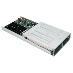

CPB01
• Support up to 2400W PDB Design to fit for 2 vertical CRPS power supply
to install on the chassis.
• Mylar insulation included that to prevent the PDB board shortcut
• Using an Amphenol-manufactured card edge connector with 3-beam contact design
to ensure stable power output.
• Perfectly fit for GM2000C-TFU and GM2400C-TFU CRPS PSU
• Full modular design with all black flat cable included.
• Support up to 6 pcs of 12V-2x6 connector to allow user could connect with latest
Nvidia/AMD graphic cards.
• PDB followed Fire Resistant (UL 94V-0) standard
• The PDB is designed with a PMBus connector to enable administrators toconveniently
monitor and read power status signals.
• Multiple protection circuitry
2400W 1U 1+1 Redundant CRPS
Fully Modular Power Distribution Board with Cage
CPB Series
1
SPECIFICATION
SilverStone CPB Series
CPB01
SST-CPB01
1U 1+1 Redundant CRPS Fully Modular Power
distribute board with cage
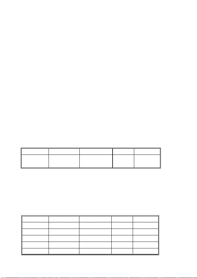
1.1 DC Input Requirements
1.2 Efficiency
The Backplane must be capable of operating with the following Conditions
The power supply must have a minimum of 88% efficiency measured at the worst case condition.
All outputs must maintain their regulation within the below limits when measured at the output
connector point or across the remote sense (if applicable) in any load condition defined in
section 2.2
This specification defines the performance characteristics of a 1U redundant power supply back panel.
Its operation temperature is at 50 degrees Celsius and the total output reaches to 2400W.
2.1 DC voltage regulation
1. Input Requirement
2. Output Requirements
Minimum Nominal Maximum Unit
Table 1.1
Vdc
Input Voltage
Range(Vdc)
11.71 12.2 12.69
Output Minimum Nominal Maximum Unit
+12V 11.40 12.00 12.60 Vdc
+5V 4.75 5.0 5.25 Vdc
+3.3V 3.14 3.3 3.47 Vdc
-12V 10.80 12.0 13.2 Vdc
+5Vsb 4.75 5.0 5.25 Vdc
Table 2.1
2
2.2 Output Current Requirements
2.3 Output Ripple and Noise
2.4 Output Dynamic Loading
All outputs must maintain their regulation as per section 2.1 when loaded to the
following loading combination:
1. Maximum continuous combined load on +3.3V and +5V outputs shall not
exceed 150W.
2. The total output power can not exceed 2400W continuously. During load
changes from minimum to maximum or maximum to minimum the unit must
not shut down.
The following output ripple/noise requirements will be met throughout the load
ranges specified in Section 2.2 and under all input voltage conditions specified
in Section 2.1. Ripple and noise are defined as periodic or random signals over
the frequency band of 10Hz to 20MHz. Measurements will be made with an
oscilloscope set to 20MHz bandwidth limit. Measurement is done by using
10uF Tantalum in parallel with a 0.1uf ceramic capacitor, measured directly
at the output connector side.
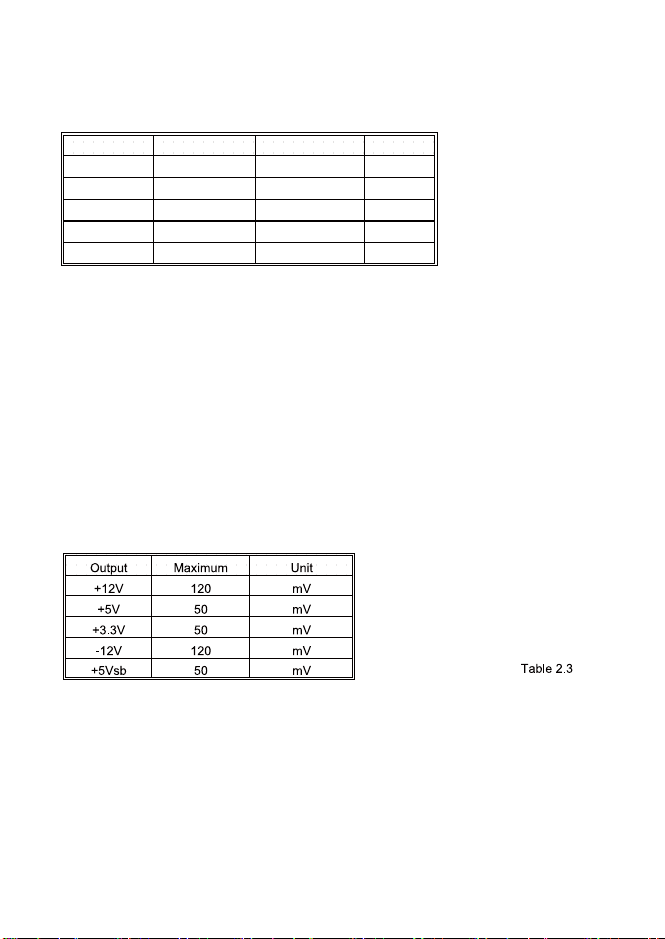
Output Minimum Maximum Unit
+12V 0.5 200 A
+5V 0.5 22 A
+3.3V 0.5 25 A
-12V 0 0.3 A
+5Vsb 0.1 3.0 A
Table 2.2
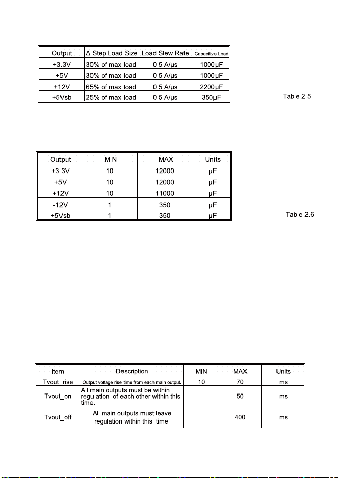
The output voltages shall remain within the limits specified in 2.2 for the step
loading and within the limits specified
in 2.6 for the capacitive loading. The load transient repetition rate shall be
tested between 50Hz and 5kHz at duty
cycles ranging from 10%-90%. The load transient repetition rate is only a test
specification. The Δ step load may
occur anywhere within the MIN load to the MAX load shown in 2.5.
3
The power supply shall be stable and meet all requirements, except dynamic
loading requirements, with the following capacitive loading ranges.
PSON# controlling the ON/OFF of the power supply.
2.6 Capacitve Loading Conditions
2.5 Transient Load Requirements
2.6 Capacitive Loading
3.1 Timing Requirements
3. Controls and Signal
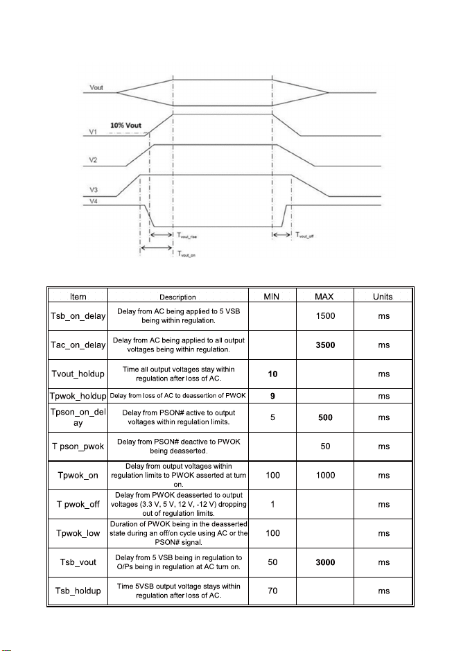
These are the timing requirements for the power supply operation. The output voltages must rise
from 10% to within regulation limits (Tvout_rise) within 10 to 70ms. The +3.3V, +5V and +12V
output voltages should start to rise at about the same time. All outputs must rise smoothness. The
+5V output needs to be greater than the +3.3V output during any point of the voltage rise. The +5
V output must never be greater than the +3.3V output by more than 2.25 V.
Each output voltage shall reach regulation within 50 ms (Tvout_on) of each other during turn on
of the power supply.
Each output voltage shall fall out of regulation within 400 ms (Tvout_off) of each other during turn
off. Figure 1 andFigure 2 the turn ON and turn OFF timing requirements. In Figure 2, the timing is
shown with both AC and PSON# controlling the ON/OFF of the power supply.
4
Output Voltage Timings Fig 1
5
3.2 PS_ON
3.3 PWOK(Power OK)
Table 1: PSON# Signal Characteristic
PWOK Signal Characteristics
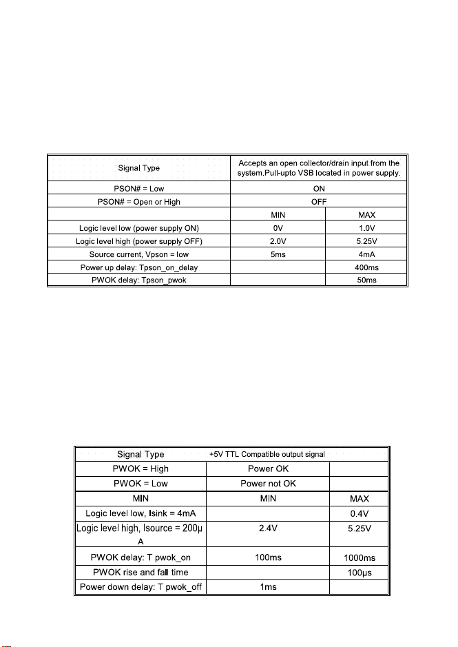
The PSON# signal is required to remotely turn on/off the power supply.
PSON# is an active low signal that turns on the +3.3V, +5V, +12V, and –12V
power rails. When this signal is not pulled low by the system,or left open, the
outputs (except the +5 VSB and Vbias) turn off. This signal is pulled to a
standby voltage by a pull-up resistor internal to the power supply.
PWOK is a power OK signal and will be pulled HIGH by the power supply to
indicate that all the outputs are within the regulation limits of the power
supply. When any output voltage falls below regulation limits or when AC
power has been removed for a time sufficiently long so that power supply
operation is no longer guaranteed, PWOK will be de-asserted to a LOW state.
For a representation of the timing characteristics of PWOK. The start of the
PWOK delay time shall be inhibited as long as any power supply output is in
current limit.
6
Protection Cicuits
3.4 Over Current Protection
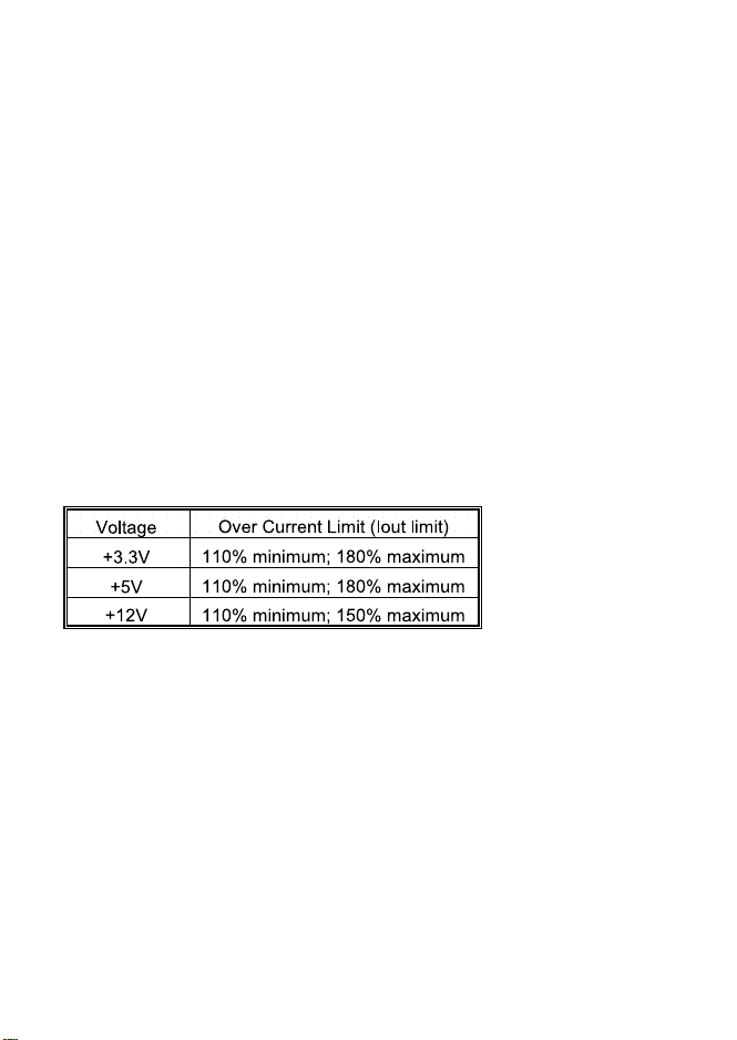
Table 4: Over Current Protection
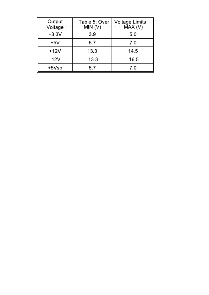
3.5 Over Voltage Protection
The power supply shall have current limit to prevent the +3.3V, +5V, and
+12V outputs from exceeding the values shown in Table 4. If the current limits
are exceeded, the power supply shall shutdown and latch off. The latch will be
cleared by toggling the PSON# signal or by an AC power interruption. The
power supply shall not be damaged from repeated power cycling in this
condition. –12 V and 5 VSB shall be protected under over current or shorted
conditions so that no damage can occur to the power supply. All outputs shall
be protected so that no damage occurs to the power supply under a shorted
output condition.
Note: When the rated output power of the installed module is lower than the
backplane output power, the module's OPP/OCP protection settings shall
take precedence.
The power supply over voltage protection shall be locally sensed. The power
supply shall shutdown and latch off after an over voltage condition occurs.
This latch shall be cleared by toggling the PSON# signal or by an AC power
interruption. Table 5 contains the over voltage limits. The values are
measured at the output of the power supply’s connectors. The voltage shall
never exceed the maximum levels when measured at the power pins of the
power
supply connector during any single point of fail. The voltage shall never trip
any lower than the minimum levels when measured at the power pins of the
Protection circuits inside the power supply shall cause only the power supply’s
main outputs to shutdown. If the power supply latches off due to a protection
circuit tripping, an AC cycle OFF for 10 seconds and a PSON# cycle HIGH for
1 second shall be able to reset the power supply.
7
3.6 Buzzer Alarm Definition
3.7 Mute Switch Definition
3.8 Alarm LED Definition
4.1 Temperature
4.1.1 Normal Operating Ambient(at sea level):
Operation temperature: 0ഒ to 50ഒ
Shipping and Storage : -40ഒ to 70ഒ
4.1.2 HUMIDITY
Operating : 20% to 90% RH
Storage : 5% to 95% RH
4.Environmental Requirements
When the PS_ON button is pressed, the buzzer on the PDB will emit a short
"beep" sound, indicating that the power supply module has started normally.
When the backplane and both power modules are operating normally, any
input power module failure (SMBAlert low), or Power Good fault (PG low) will
trigger the buzzer alarm.
After the buzzer alarm is triggered, it helps users quickly locate the faulty
module by sound. If the fault is not removed while the system remains
powered, the buzzer will stay in alarm state untill the power supply fault is
cleared or the system power is turned off, after which the alarm will gradually
disappear. It the alarm noise causes disturbance in the working environment,
the user can press the mute switch on the back panel to forcibly stop the
buzzer alarm.
The LED blinks as an alert to help users locate the faulty unit through visual
observation.
The LED signal is derived from the PSU (SMBAlert). When either PSU1 or
PSU2 has a low-level (SMBAlert) signal,the LED will blink. When both PSUs
output a high-level signal, the LED remains steadily on.
8
4.1.3 ALTITUDE
5.1 MTBF
5.2 ROHS
6.1 Intput Connector
Operating: to 10,000 feet (3,023 meters)
Non-operating: to 35,000 feet (10,580 meters)
This power supply is compliant with ROHS requirements.
The life requirement shall be met the following condition. And the environmental
temperature is assumed to be 25℃.Normal operation (at the rated input/output):
100,000hr.
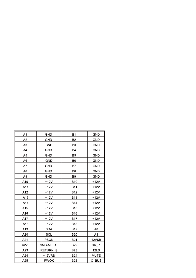
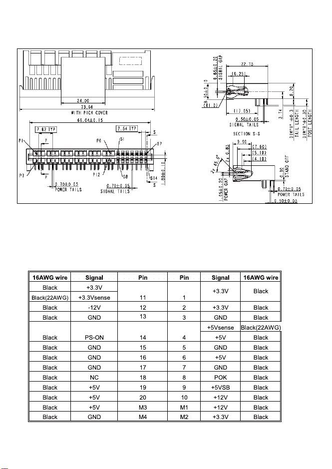
The power supply will provide a card edge connector compatible with the backplane.
See power supply mechanical drawing for dimensions. The power supply connector
is 50pins (25 pair) 90 /180degrees connector.
5. MTBF and Quality Data
6. Mechanical Drawing
Power and Signal Connection
9
Note: The signal pins on the power supply connector will be gold plated to 30 microns.
1U Dim: L353mm W153.8mm H45.2mm
M/B 20+4PIN Connector (Molex C4202H02-A20P+A4P or equivalent)
7. Physical dimension:
8. Connectors (INTEL approved equivalent):
10
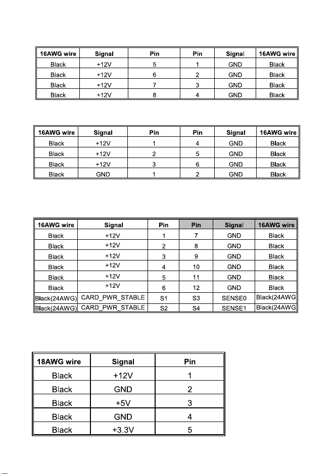
CPU 4+4PIN Connector (Molex C4202H02-A04P or equivalent)
PCIe (6+2)PIN Connector (Molex P6-I42002K or equivalent)
PCIe 12+4PIN:12V-2x6 Auxiliary Power Connector Pin Assignment
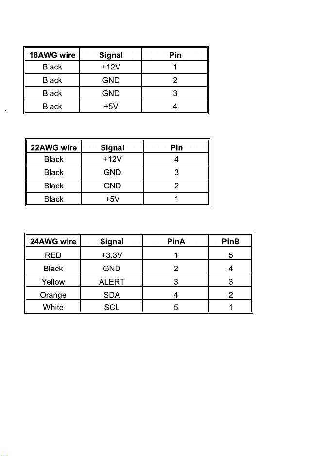
SATA 5PIN Connector (Molex P5-112702T00 or equivalent)
11
HDD 4PIN (AMP 1-480424-0 or Molex 8981-04P or equivalent)
Floppy 4PIN (AMP 171822-4 or equivalent)
5PIN PMBus Connector
PMBus Definition
Server systems are all equipped with PMBus communication capability.
This power distribution board is designed with an additional connector for PMBus
communication, which is used to query FRU data and obtain power supply
related information.
12
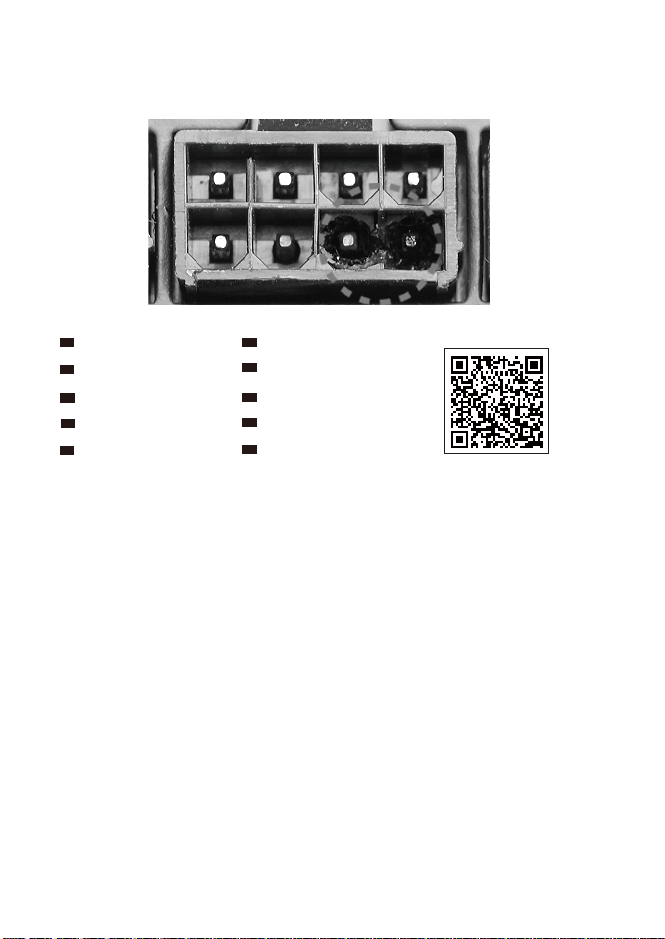
9. POWER SUPPLY CONNECTOR OVERUSE DEFINITION
Definition einer Überlastung des
Netzanschlusses
DE
Définition de l'utilisation excessive du
connecteur d'alimentation électrique
FR
Definizione di uso eccessivo del connettore
di alimentazione
IT
Definición de uso excesivo del conector de
la Fuente de alimentación
ES
Определение чрезмерной нагрузки на
коннектор блока питания
RU
電力供給コネクタの使用限度超過に関する説明
JP
⬉⑤կᑨ఼༈䖛ᑺՓ⫼ᅮН
CN
䳏⑤կឝ఼丁䘢ᑺՓ⫼ᅮ㕽
TW
ขีดจำกัดการรองรับการใช้งานของขั้วต่อจากพาวเวอร์ซัพพลาย
TH
전원 공급 커넥터 과용 정의
KR
Please refer to SilverStone website for latest specifications updates.

G11257330