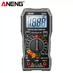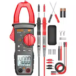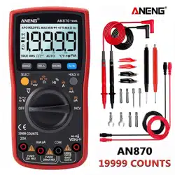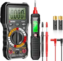
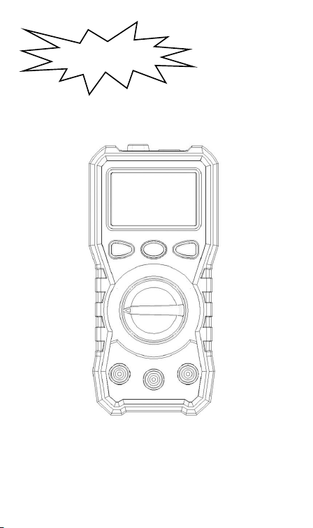
BACK LIGHT
D I G I TA L
M U LT I M E T E R
OPERATOR’S
MANUAL

- 2 -
LIMITEDWARRANTYANDLIMITATIONOF LIABILITY
This product will be free from defects in material and workmanship for
one year fromthe dateofpurchase.This warranty does notcover fuses,
disposable batteries, or damage from accident, neglect, misuse,
alteration, contamination, or abnormal conditions of operation or
handling. Resellers are not authorized to extend any other warranty on
our behalf.Toobtainservice during the warrantyperiod, returnthe unitto
point of purchase or to Service Center by freight prepare with a
descriptionofthe problem.
THIS WARRANTY IS YOUR ONLY REMEDY. NO OTHER
WARRANTIES, SUCH AS FITNESS FOR A PARTICULAR
PURPOSE, ARE EXPRESSED OR IMPLIED. WE ARE NOT
LIABLE FOR ANY SPECIAL, INDIRECT, INCIDENTAL OR
CONSEQUENTIAL DAMAGES OR LOSSES, ARISING FROMANY
CAUSE OR THEORY. Since some states or countries do not allow the
exclusion or limitation of an implied warranty or of incidental or
consequentialdamages,thislimitationof liability maynot apply toyou.
WARNING AND PRECAUTIONS
To avoid possible electric shock or personal injury, and to
avoid possible damage to the meter or to the equipment
under test, comply with the follow practices:
Do not use the meter if it is damaged. Before you use the
meter, inspect the case. Pay particular attention to the
insulation surrounding the connectors.
Inspect the test leads for damaged insulation or exposed
metal. Check the test leads for continuity. Replace
damaged test leads before you use the meter.
Do not use the meter if it operates abnormally. Protection
may be impaired. When in doubt, have the meter
serviced.
Do not operate the meter around explosive gas, vapor,
or dust.
Do not apply more than the rated voltage, as marked on
the meter, between terminals or between any terminal
and earth ground.
Before use, verify the meter’s operation by measuring a
known voltage.
When measuring current, turn off circuit power before
connecting the meter in the circuit.

- 3 -
When servicing the meter, use only specified
replacement parts. Do not use the Meter in a manner not
specified by this manual or the safety features of the
Meter may be impaired.
Use with caution when working above 30V ac rms, 42V
ac peak, or 60V dc. Such voltages pose a shock hazard.
When using the probes, keep your fingers behind the
finger guards on the probes.
Connect the common test lead before you connect the
live test lead. When you disconnect test leads,
disconnect the live test lead first.
Remove the test leads from the meter before you open
the battery door.
Do not operate the meter with the battery door or
portions of the cover removed or loosened.
To avoid false readings, which could lead to possible
electric shock or personal injury, replace the batteries as
soon as the low battery indicator (“ ”) appears.
International symbols used on the Meter and in this manual are
explainedTable1.
Table1.InternationalElectricalSymbols
AC (Alternating Current).
DC (Direct Current).
AC or DC
Battery
Safety information. Refer to the manual.
Dangerous voltage may be present.
Earth ground.
Fuse.
Conforms to European Union directive.
Double insulated.
Safety Compliance: EN 61010-1, 2000 CAT II 500V overvoltage
standards. Do not measure voltages above 500V in Category II
installations, but for professional engineer can measure upto
DC1000VandAC750VwithinCATI.
Overvoltage installation categories per EN 61010-1, 2000: The Meter is
designedtoprotectagainst transientsinthesecategories:
CATI From high-voltage low-energy sources, e.g., electronic circuits
ora copymachine.
CATII From equipment supplied from the fixed installation, e.g., TVs,
- 4 -
PCs,portabletoolsand household appliances.
CAT III From equipment in fixed equipment installations, e.g.,
installation panels, feeders and short branch circuits, and
lighting systems in large buildings.
General Specifications
Maximum Voltage between any Terminal and Earth
Ground: 600V
Measurementrate: updates2-3/sec.
Overrange indication:“1” figure onlyin thedisplay
Automaticnegativepolarityindication.
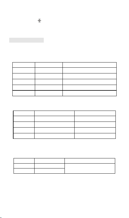
The “ ” is displayed when the battery voltage drops below the
operatingvoltage.
Operatingtemperature:0°C~40°C,0~75% R.H.
Storagetemperature:-10°C~50°C,0~75% R.H.
Power supply: two standard 1.5v AAA batteries.
Dimensions: 148L*74W*45Hmm.
Weight:approx140g (includingbattery)
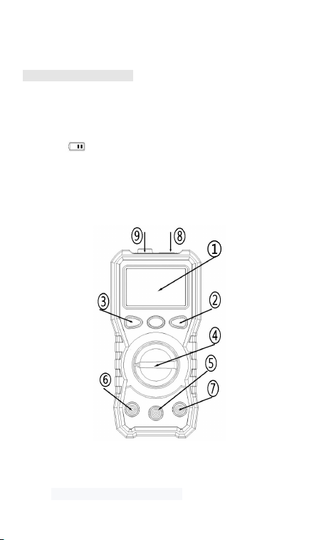
FRONT PANEL DESCRIPTION
1. LCD Display
2. HOLD /BACKGROUND LIGHT button
3. FUNCTION SWITCH button
4. FUNCTION AND RANGE SWITCH
- 5 -
5. “COM” JACK
6. “10A” JACK
7. “VΩmA ” JACK
8. Flashlight lighting
9. Non - contact voltage sensor
SPECIFICATIONS
Accuracies are guaranteed for 1 year, 23℃±5℃, less than
80%RH
DC VOLTAGE
Range
Resolution
Accurate
200mV
0.1mV
(1%+5)
2V
1mV
(0.8%+2)
20V
10mV
(0.8%+2)
200V
100mV
(0.8%+2)
600V
1V
(0.8%+5)
OVERLOAD PROTECTION: 220V rms AC for 200mV range
and 600V DC or 600V rms for all ranges.
DC CURRENT
Range
Resolution
Accurate
2mA
1uA
(1.5%+5)
20mA
10uA
(1.5%+5)
200mA
0.1mA
(1.5%+5)
10A
0.1A
(2.5%+5)
OVERLOAD PROTECTION: 200mA 250V fuse (10A range
unfused).
MEASURING VOLTAGE DROP: 200mV
AC VOLTAGE
Range
Resolution
Accurate
200V
100mV
(2.0%+10)
600V
1V
RESPONSE: Average responding, calibrated in rms of a
sine wave.
FREQUENCY RANGE: 40Hz ~ 400Hz
OVERLOAD PROTECTION: 600V DC or 600V rms for all
ranges.
- 6 -
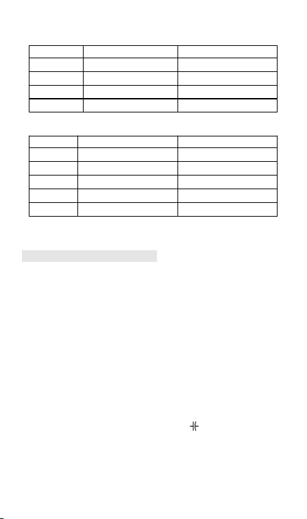
CAPACITANCE
Range
Resolution
Accurate
20nF
10pF
(3%+5)
200nF
100pF
(3%+4)
20uF
10nF
(3%+8)
2000uF
1uF
(5%+10)
RESISTANCE
Range
Resolution
Accurate
200Ω
0.1Ω
(1.5%+5)
20KΩ
10Ω
(1.0%+4)
200KΩ
100Ω
(1.0%+4)
2MΩ
1KΩ
(1.0%+4)
200MΩ
100KΩ
(4.0%+10)
MAXIMUM OPEN CIRCUIT VOLTAGE: 3.0V.
OVERLOAD PROTECTION: 15 seconds maximum
220Vrms.
OPERATING INSTRUCTIONS
WARNING
To avoid electrical shock hazard and or damage of
the instrument, do not measure voltages that
might exceed 600V above earth ground.
Before the use of instrument, inspect test leads,
connectors and probes for cracks, breaks, or
crazes in the insulation.
Dangerous voltages may be present at the input
terminals and may not be displayed.
To avoid electrical shock or damage to the Meter
when measuring resistance or continuity in a
circuit, make sure the power to the circuit is
turned off and all capacitors are discharged.
DC & AC VOLTAGE MEASUREMENT
1. Connect red test lead to “VΩmA ” jack, Black lead to
“COM” jack.
2. Set RANGE switch to desired VOLTAGE position, if
the voltage to be measured is not known before hand,
set switch to the highest range and reduce it until
satisfactory reading is obtained.
- 7 -
3. Connect test leads to device or circuit being
measured.
4. Turn on power of the device or circuit being measured
voltage value will appear on Digital Display along with
the voltage polarity.
DC CURRENT MEASUREMENT
1. Red lead to “VΩmA ”. Black lead to “COM” (for
measurements between 200mA and 10A connect red
lead to “10A” jack with fully depressed.)
2. RANGE switch to desired DCA position.
3. Open the circuit to be measured, and connected test
leads INSERIES with the load in with current is to
measure.
4. Read current value on Digital Display.
5. Additionally, “10A” function is designed for intermittent
use only. Maximum contact time of the test leads with
the circuit is 15 seconds, with a minimum intermission
time of seconds between tests.
RESISTANCE MEASUREMENT
1. Red lead to “VΩmA ”. Black lead to “COM”.
2. RANGE switch to desired OHM position.
3. If the resistance being measured is connected to a
circuit, turn off power and discharge all capacitors
before measurement.
4. Connect test leads to circuit being measured.
5. Read resistance value on Digital Display.
DIODE MEASUREMENT
1. Red lead to “VΩmA ”, Black lead to “COM”.
2. RANGE switch to “ ” position.And press "SEL" to
select the ( ) function.
3. Connect the red test lead to the anode of the diode to
be measured and black test lead to cathode.
4. The forward voltage drop in mV will be displayed. If
the diode is reversed, f“OL”will be shown.
AUDIBLE CONTINUITY TEST
1. Red lead to “VΩmA ”, Black lead to “COM”.
2. RANGE switch to “ ” position.And press "SEL" to
select the ( ) function.
Connect test leads to two points of circuit to be tested. If the
resistance is lower than 30Ω±20Ω, the buzzer will sound.
CAPACITANCE MEASUREMENT

- 8 -
1. Red lead to “VΩmA ”, Black lead to “COM”.
2. RANGE switch to desired Capacitance position.
3. Turn off power and discharge all capacitors before
measurement.
4. Connect the test lead to both ends of the capacitance
under test.
5. Read Capacitance value on Digital Display.
INDUCED VOLTAGE TEST
1. RANGE switch to desired “NCV” position.
2. The induced voltage sensor above the table is close
to the ac charged body.
3. When the sensor detects the presence of ac voltage,
the buzzer will sound and the display screen will
display the intensity of the corresponding induced
voltage.
MAINTENANCE
Tocleanthe terminals
a)Turnthe MeterOFF and removethe testleads.
b)Shakeout anydirtthatmay be inthe terminals.
c) Soak a new swab with isopropyl alcohol and work around the inside
ofeachinputterminal.
d) Use a new swab to apply a light coat of fine machine oil to the inside
ofeachterminal.
BATTERY REPLACEMENT
1)Battery replacement should only be done after the test leads have
beendisconnectedand powerisoff.
2)Remove the battery cover at the bottom.
3)The meter is powered by two single 1.5V battery.Remove
the old battery from the battery bin at the bottom of the
meter and reload the new battery.And cover the battery
cover.
Button function
1.“SEL”:Function selection button .
2.“ ”:Short press this button to hold/release the value;
Long press this button for 2 seconds to turn the
screen backlight and lighting on/off.
ACCESSORIES
Operator’s instruction manual
Set of test leads(CAT II 600V 10A , work )
1.5v AAA battery X 2