Ͳ ϭ Ͳ
Ͳ Ϯ Ͳ
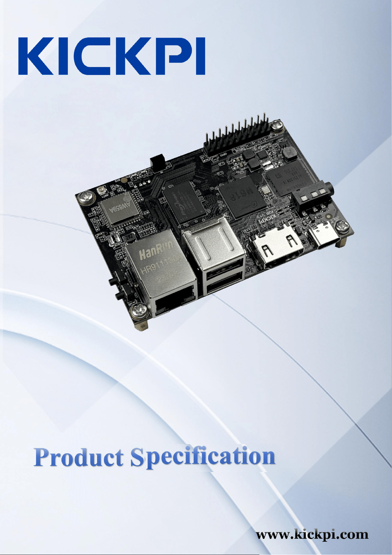
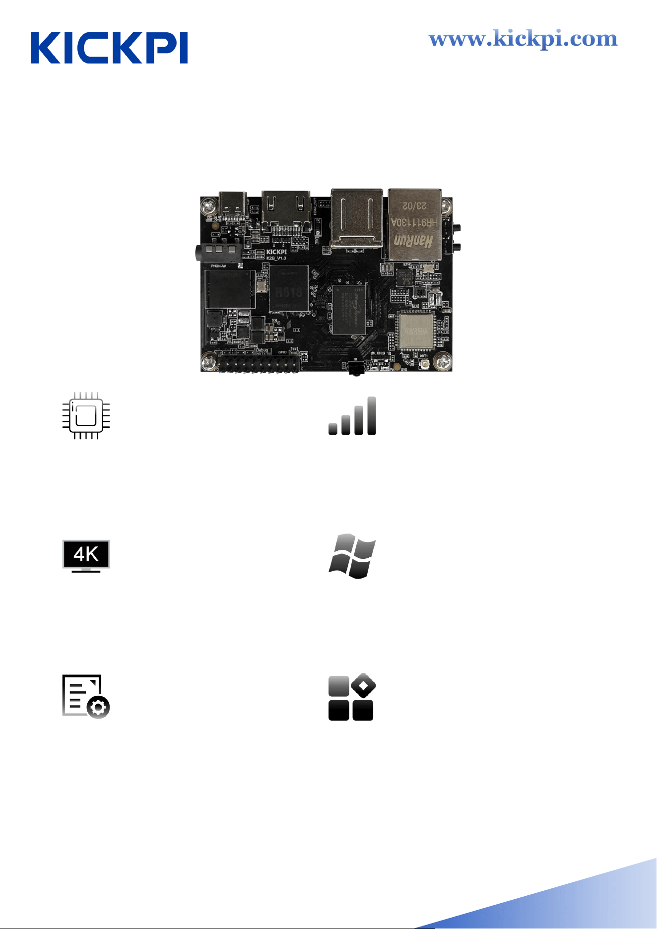
4XDGFRUH ELW SURFHVVRU
4XDGFRUH ELW &RUWH[$
SURFHVVRU $OOZLQQHU +
0DLQ IUHTXHQF\ XS WR *+] ORZ SRZHU
FRQVXPSWLRQ DQG KLJK SHUIRUPDQFH
3RZHUIXO QHWZRUN
FRPPXQLFDWLRQ IXQFWLRQ
(TXLSSHG ZLWK JLJDELW KLJKVSHHG DQG ODUJH
QHWZRUN LQWHUIDFH KDYH VWDEOH FRPPXQLFDWLRQ
DQG IDVWHU VSHHG VXLWDEOH IRU YDULRXV VFHQH
UHTXLUHPHQWV
. YLGHR GHFRGLQJ
.#ISV 9LGHR GHFRGLQJ
6XSSRUWV +'0, GLVSOD\ LQWHUIDFH
6XSSRUWV PXOWLSOH V\VWHP
RSHUDWLRQV
6XSSRUWV WZR PDMRU V\VWHPV $QGURLG
DQG 8EXQWX SURYLGHV V\VWHP FDOO $3,
UHIHUHQFH FRGH DQG SHUIHFWO\ VXSSRUWV WKH
GHYHORSPHQW RI XSSHU OHYHO DSSOLFDWLRQ DSSV
DQG 6'.V IRU FXVWRPHUV
(IILFLHQW VHFRQGDU\ GHYHORSPHQW
DQG LQGHSHQGHQW FXVWRPL]DWLRQ
(PEHGGHG RSHUDWLQJ V\VWHP XQGHUO\LQJ
GULYHUV SURYLGLQJ WHFKQLFDO LQIRUPDWLRQ DQG
(QJLQHHU RQHRQRQH VHUYLFH HQDEOHV XVHUV WR
HIILFLHQWO\ SHUIRUP VHFRQGDU\ RSHQLQJ
'HYHORS DQG TXLFNO\ EXLOG LQGHSHQGHQW DQG
FRQWUROODEOH SURGXFWV
:LGHO\ DSSOLFDEOH ILHOGV
0DLQO\ WDUJHWLQJ WKH FXVWRPL]HG PDUNHW IRU
VHWWRS ER[HV NDUDRNH PDFKLQHV YLGHR
FRQIHUHQFLQJ WHUPLQDOV SURMHFWRUV DQG RWKHU
LQGXVWULHV
�、 Product Features
Ͳ ϯ Ͳ
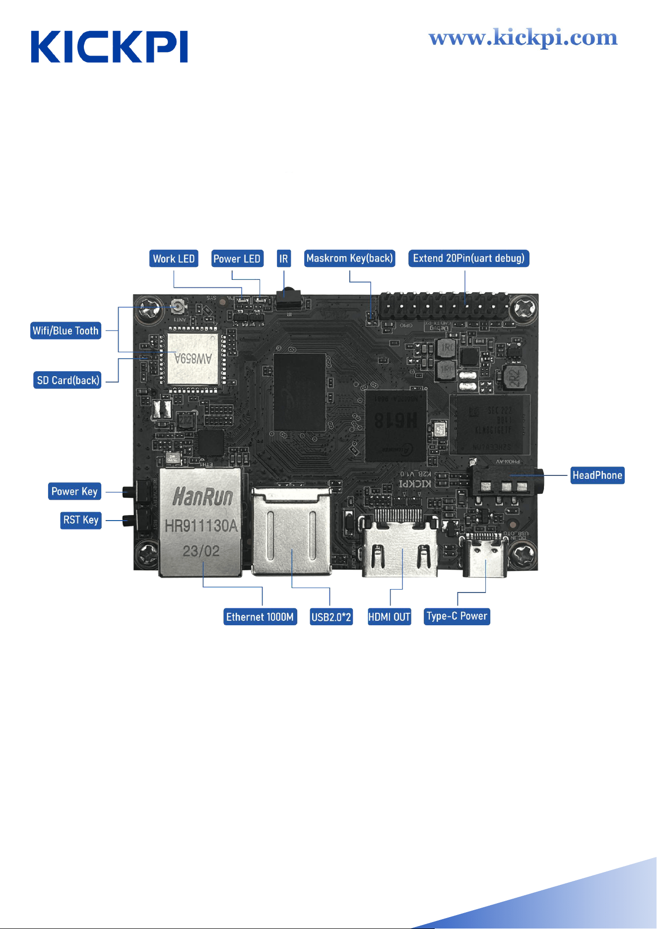
�、 Interface Description

Ͳ ϰ Ͳ
)XQFWLRQ
0DLQ 3DUDPHWHU
0DLQ &RQWUROOHU
$OOZLQQHU +
&38
4XDGFRUH &RUWH[$ XS WR *+]
*38
0DOL * 03
0HPRU\
* * * /3''5
6WRUDJH
* * * H00&
6\VWHPV 6XSSRUWHG $QGURLG 8EXQWX
3RZHU 6XSSO\
7\SH& 9
/(' /LJKW 3RZHU /(' :RUN /('
86% +267
86% +267 ;
86% 27*
86% 27* ;
,QIUDHG 5HFHLYHU
<
'HEXJ 6HULDO 3RUW
<
%XWWRQV
5HFRYHU\ .(< 5(6(7 .(< )(/ .(<
([SDQVLRQ 3LQV
([WHQG 3LQ 7RWDO 3LQ 8$57 ; 63, ; 3:0 ; ,& ; ,6 ;
63',) ; 86% ;
+'0, 'LVSOD\
; XS WR .#+]
6'&DUG <
(WKHUQHW
0 ;
�、 Specif ications
Ͳ ϱ Ͳ
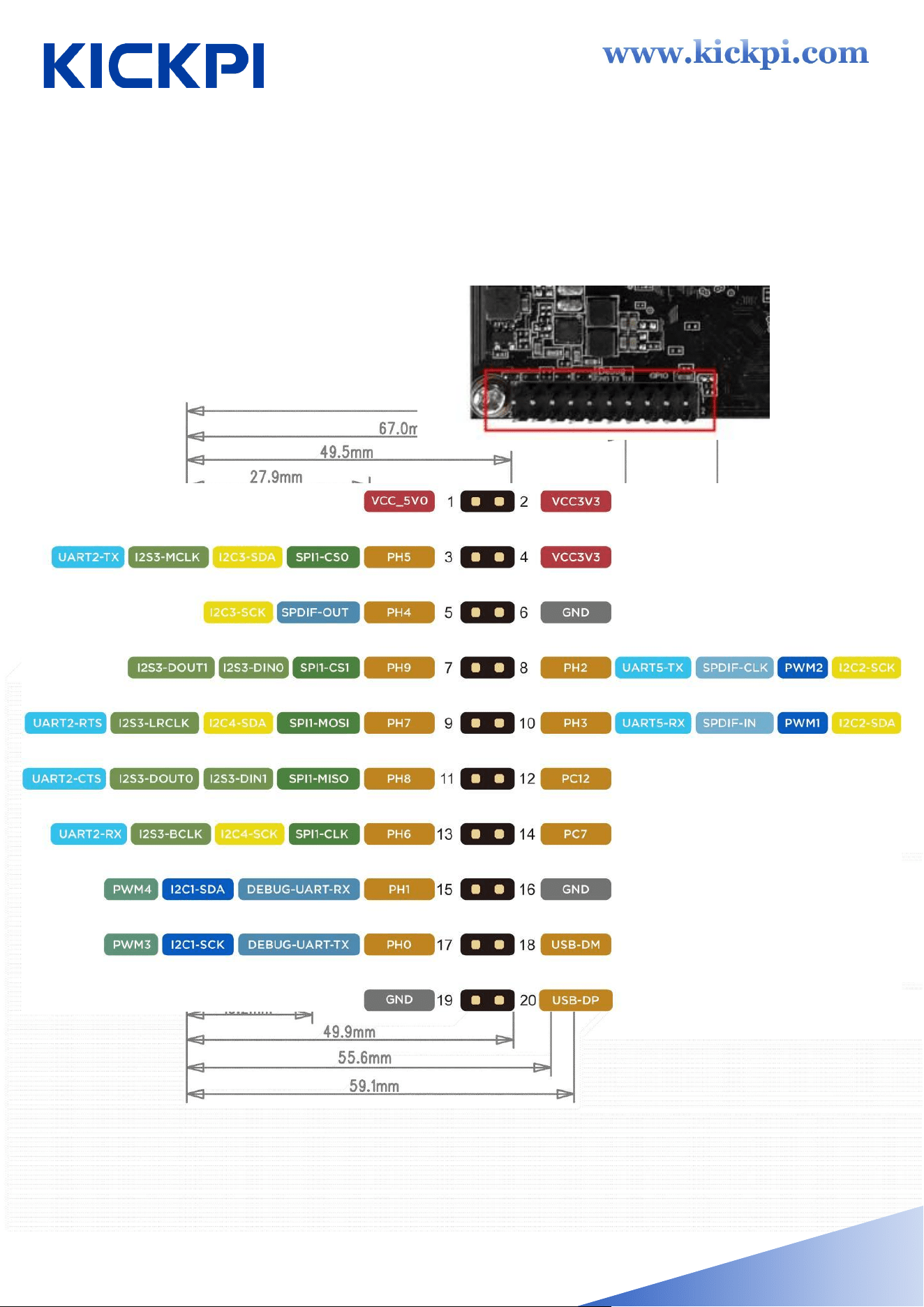
3LQ 'HILQLWLRQ
�、 Interface Illustration
- 5 -

www.kickpi.com
�、 What can I d
o with K�B?
Home Entertainment:It is suitable for scenarios such as smart TV
boxes, supports 4K@60fps video encoding, and can provide users
with a clear and smooth video playback experience.
• Smart Home:It supports access to various sensors and peripheral
devices, and enables the interconnection and centralized control of
smart home devices.
• IoT Devices:It is widely used in the Internet of Things (IoT) field,
such as intelligent monitoring devices and intelligent environmental
monitors, enabling the collection, processing and transmission of
data.
• Development Platform:It adopts Allwinner H618 as the main con-
trol chip, providing an ideal development platform for professionals in
the embedded and computing industries.
- 6 -

www.kickpi.com
�、 How to Use and Install KICKPI K�B ?
K2B can be powered by both Android and Linux. when Linux is in use,
Like most Pi products, K2B can work in headless mode( no display
connected, access via ssh ) and desktop mode( Ubuntu).
To start using K2B as a Linux interactive computer , you need to pre-
pare the following items:
• Power Supply
• Display and Display Cable
• Boot Media
• Keyboard and Mouse
Tool Preparation and Installation
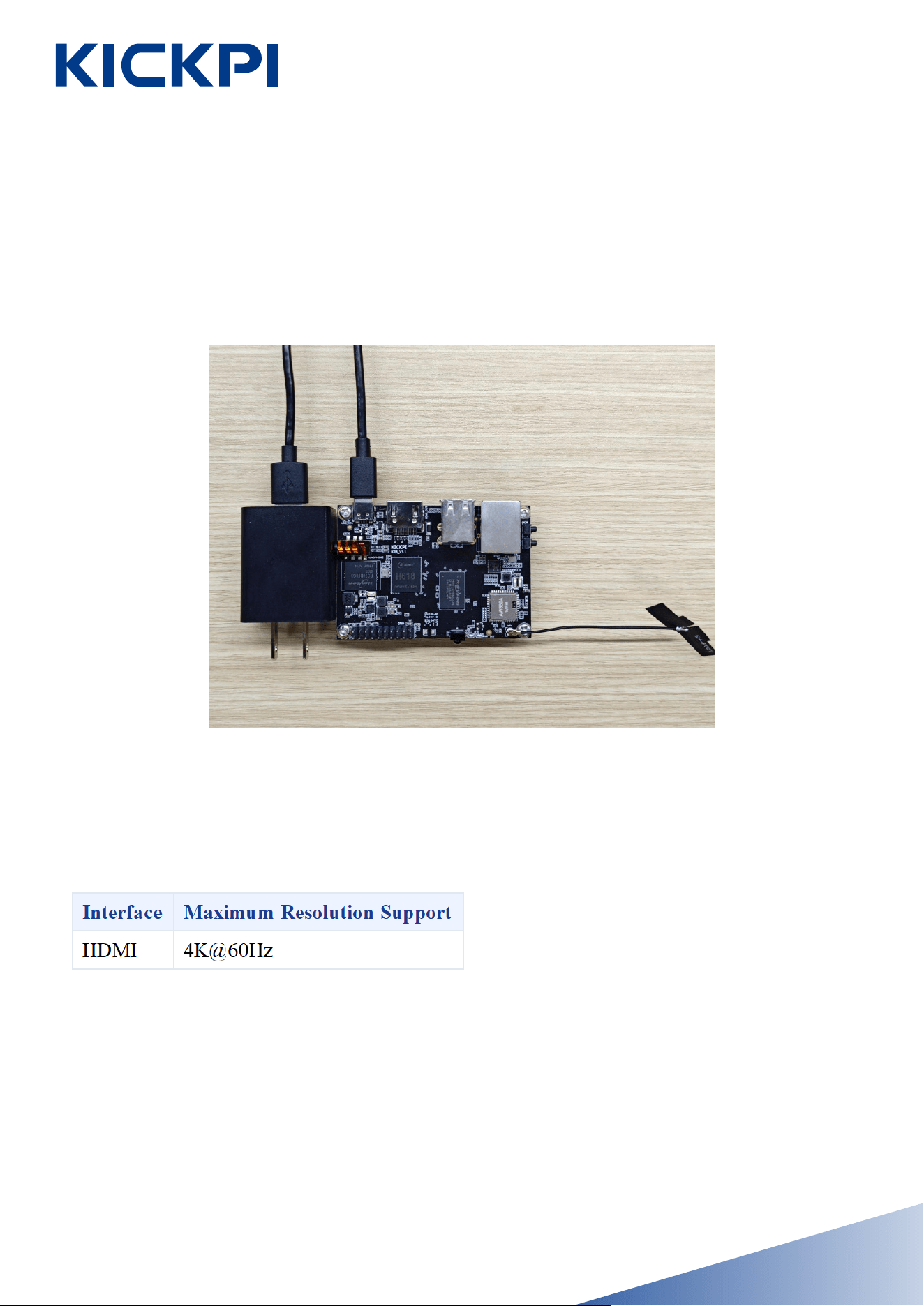
Power Supply
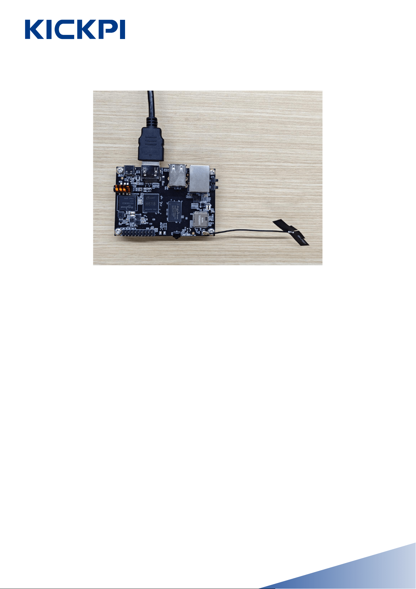
K2B only supports 1 power mode.
- 7 -
www.kickpi.com
- 8 -
Display
Power supply connection demonstrated:
www.kickpi.com
B
oot Media
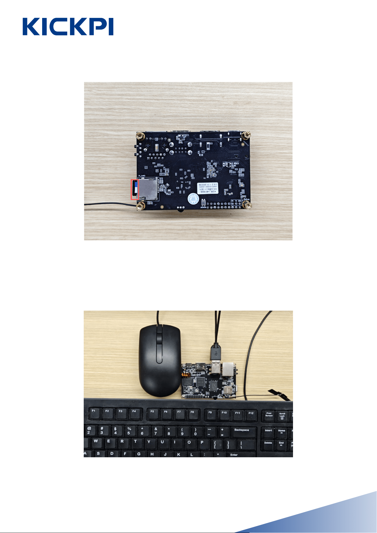
The K2B is available in two versions: on-board eMMC (embed-ded
Multi Media Card) and no on-board eMMC. The on-board eMMC
version comes pre-installed with the Android 12 operating system at
the factory, requiring no additional boot media. However, for subse-
quent use (the no on-board eMMC version must be equipped with an
SD card), if you wish to replace the operating system or boot from an
SD card, you need to prepare an SD card with a storage capacity of ≥
16GB.
- 9 -
www.kickpi.com
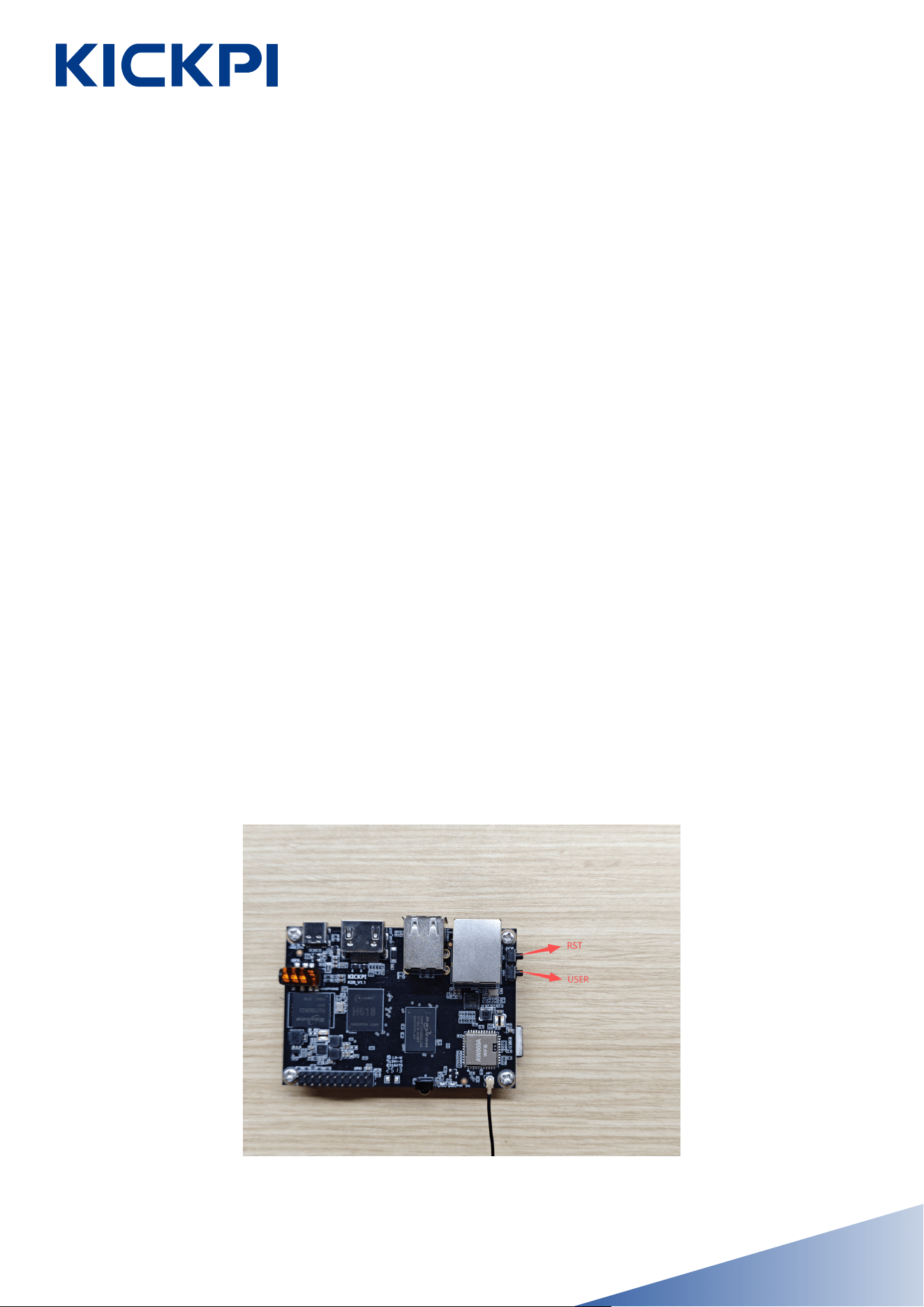
Keyboard and Mouse
K2B has 2 USB 2.0 ports. You can use any one of them to connect a
keyboard or
- 10 -
www.kickpi.com
Buttons
K2B has 3 physical buttons on-board, each one has unique function,
here are their usage description:
• RST: Short press to hot reset device once.
• USER: Ubuntu Desktop Edition: A short press opens the Logout in-
terface; Ubuntu Server Edition: A short press of the USER button shuts
down the device directly; Android System: A short press turns off the
screen.
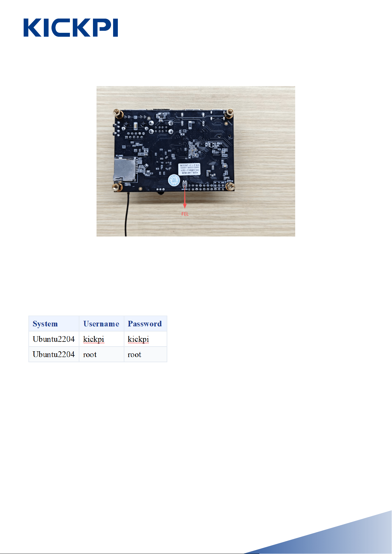
• FEL: Located on the bottom side of the board. It is used in the sce-
nario of installing OS Image to on-board eMMC,when pressed and hold
with a power-on action, SoC's Init code will put device into MASKROM
mode, cooperate with flashing tool to install Image into eMMC.
MASKROM mode means cheating SoC init code into thinking eMMC
has nothing programmed, even without U-boot or U-boot is corrupted
and unable to work correctly. It give people a chance to reprogram
eMMC after bricking it.
- 11 -
www.kickpi.com
System Startup
User and Password
For any Linux distro Image we released, Default user and password for
different distros are as follows:
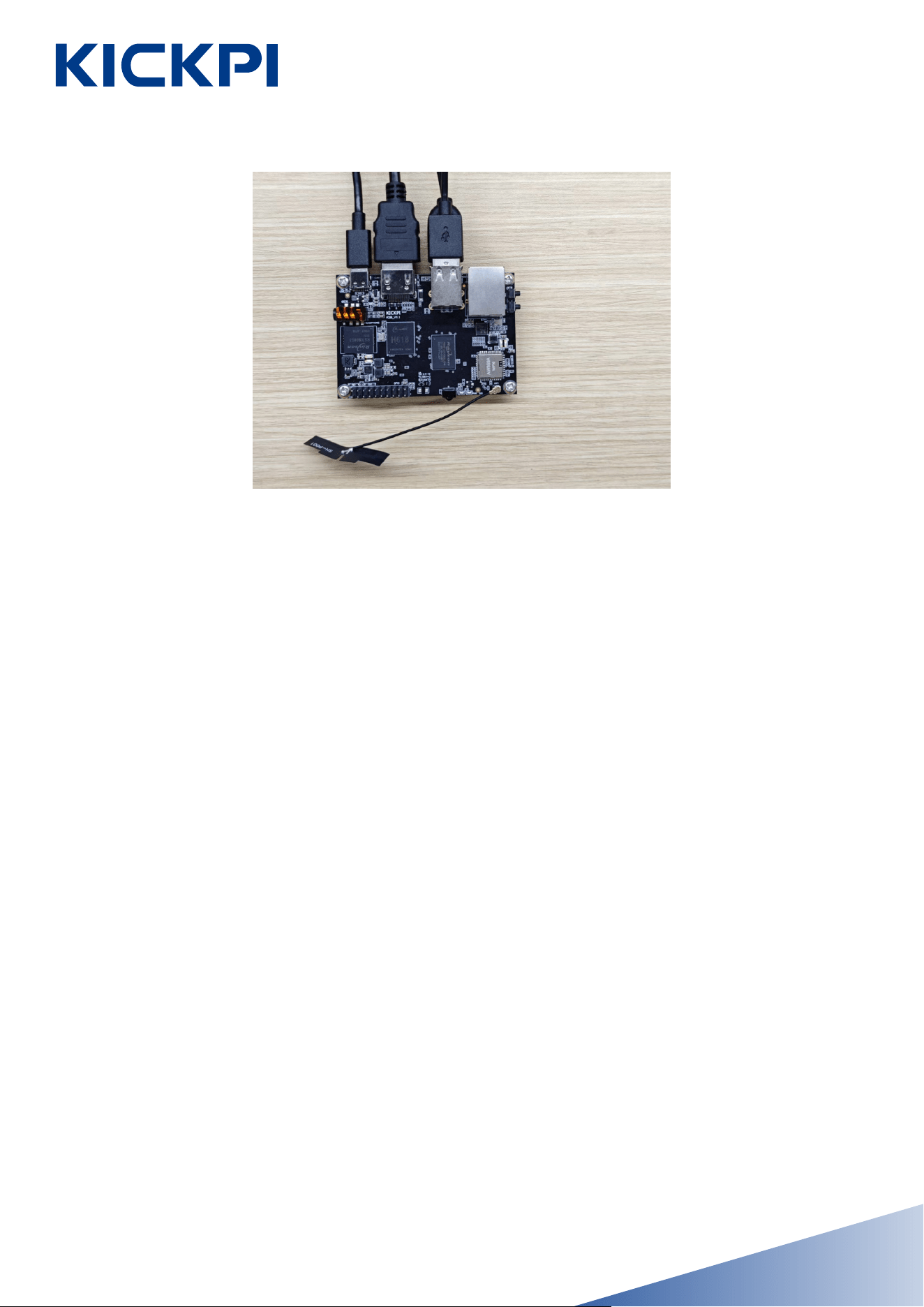
Hardware Installation
In below installation diagram, we have installed the power supply, HDMI
display, mouse, and keyboard to KickPi K2B (If in you scenario , K2B
works as a headless device and without display, here is a way to tell
how the device’s working and trouble shoot issues via on-board LED).
FPC Antenna has bare metal surface, should avoid direct contact with
board. Antenna may also generate electromagnetic interference , harm
DDR’s signals, please place antenna spatially away from DDR and SoC.
- 12 -
www.kickpi.com
- 13 -
LED Status Indicator
You can tell the system working status via the LED indicators.
• K2B board has two LED indicators. green LED is the power indica-
tor, and blue LED is the heartbeat indicator.
Success: Green LED is steady on, blue LED is blinking.
Failure: If green LED is off when device is powered on, please check
power supply or short circuit issue. green LED sucks current directly
from DC power without any external control. If the blue LED is off or
steady on(no blinking), kernel panic or died. Blinking is controlled by a
kernel driver. All our released OS Image work this way: Android, Ubun-
tu,Debian,Armbian.
System Desktop
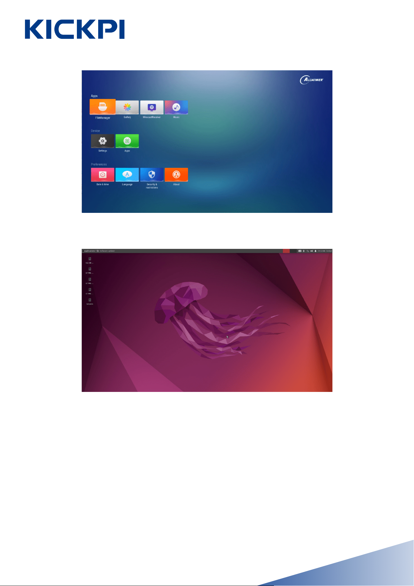
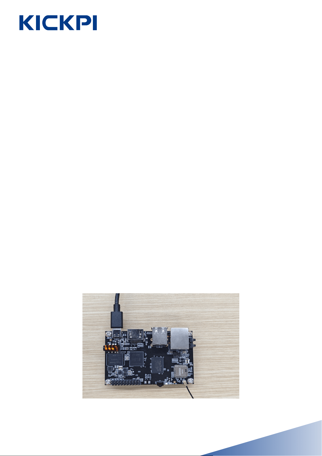
K2B supports Android, Ubuntu operating systems. When our released
OS images been installed, each one use different desktop wallpaper.
Android12.0
The K2B supports Android TV and Android tablet operating systems,
and the one shown in the figure is the Android TV operating system.
www.kickpi.com
- 14 -
Installing Operating System
The Android image for the Kickpi K2B supports both SD card installa-
tion and USB installation, while the Ubuntu image currently only sup-
ports SD card installation. Motherboards equipped with an eMMC
module come pre-flashed with the Android 12 system image by default
at the factory.
Ubuntu22.04 xfce
www.kickpi.com
Obtaining Image
Obtain Kickpi K2B image files from OneDrive.
Android Image USB Installation
Install the Android image via USB. Please check if the development
board has an onboard eMMC. If it does not have one, you can skip this
, in this scenario, board can only only boot from SD boot card.
Preparation
Hardware: DC 12V independent power supply, USB A-to-C cable.
Software: Installing tool PhoenixSuit, Android image.
Steps
1. The board enters the Installation Mode,the green LED stays on.
Installation Mode: When the board is powered off, long-press the
FEL button on the bottom side of the board, then connect the power
supply. The green light on the board will stay on, indicating successful
entry into Installation mode. When the board is powered on, first press
and hold the FEL button,don't let loose, then press RST button. The
green light will stay on, indicating successful entry into Installation
mode.
- 15 -
www.kickpi.com
- 16 -
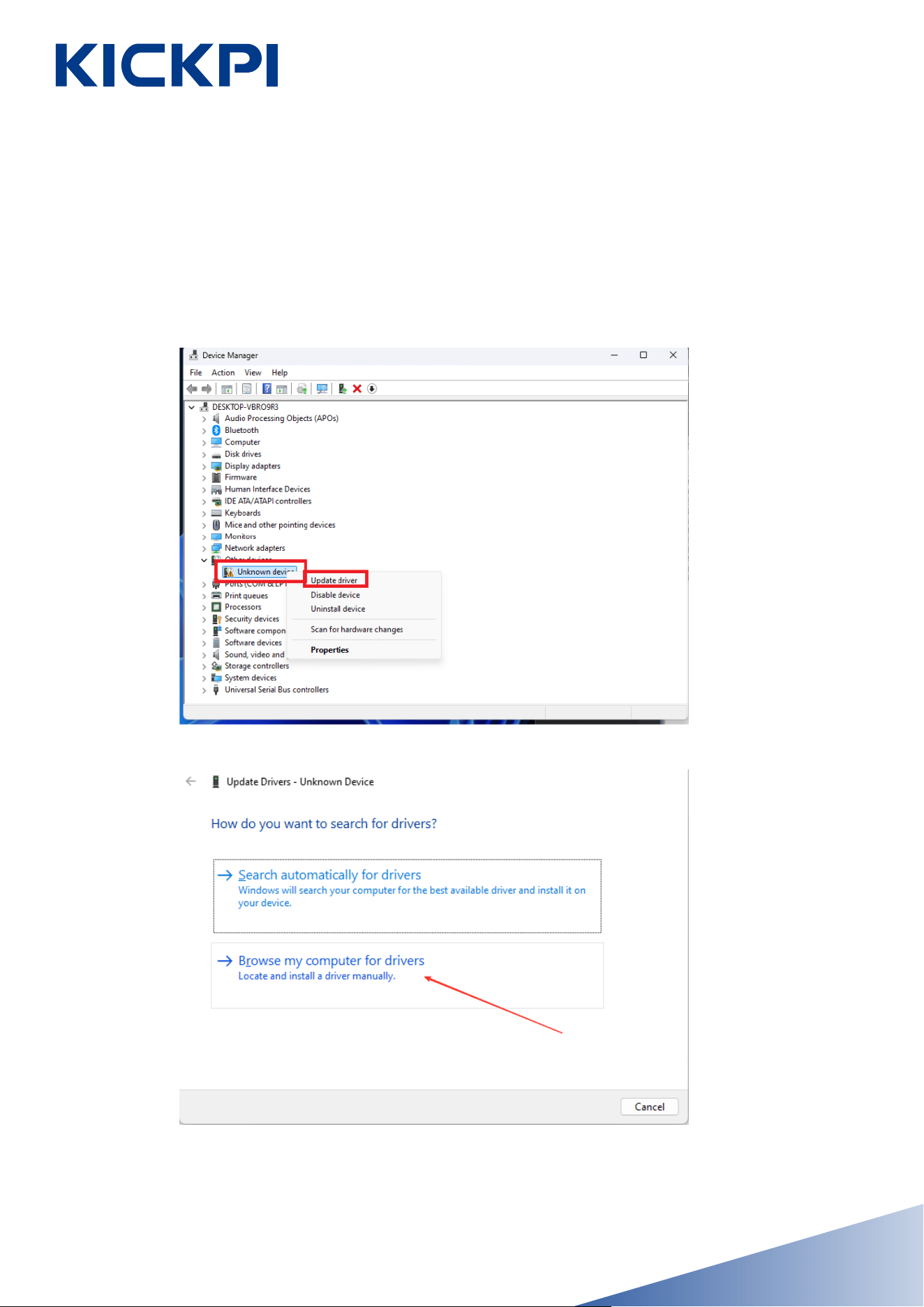
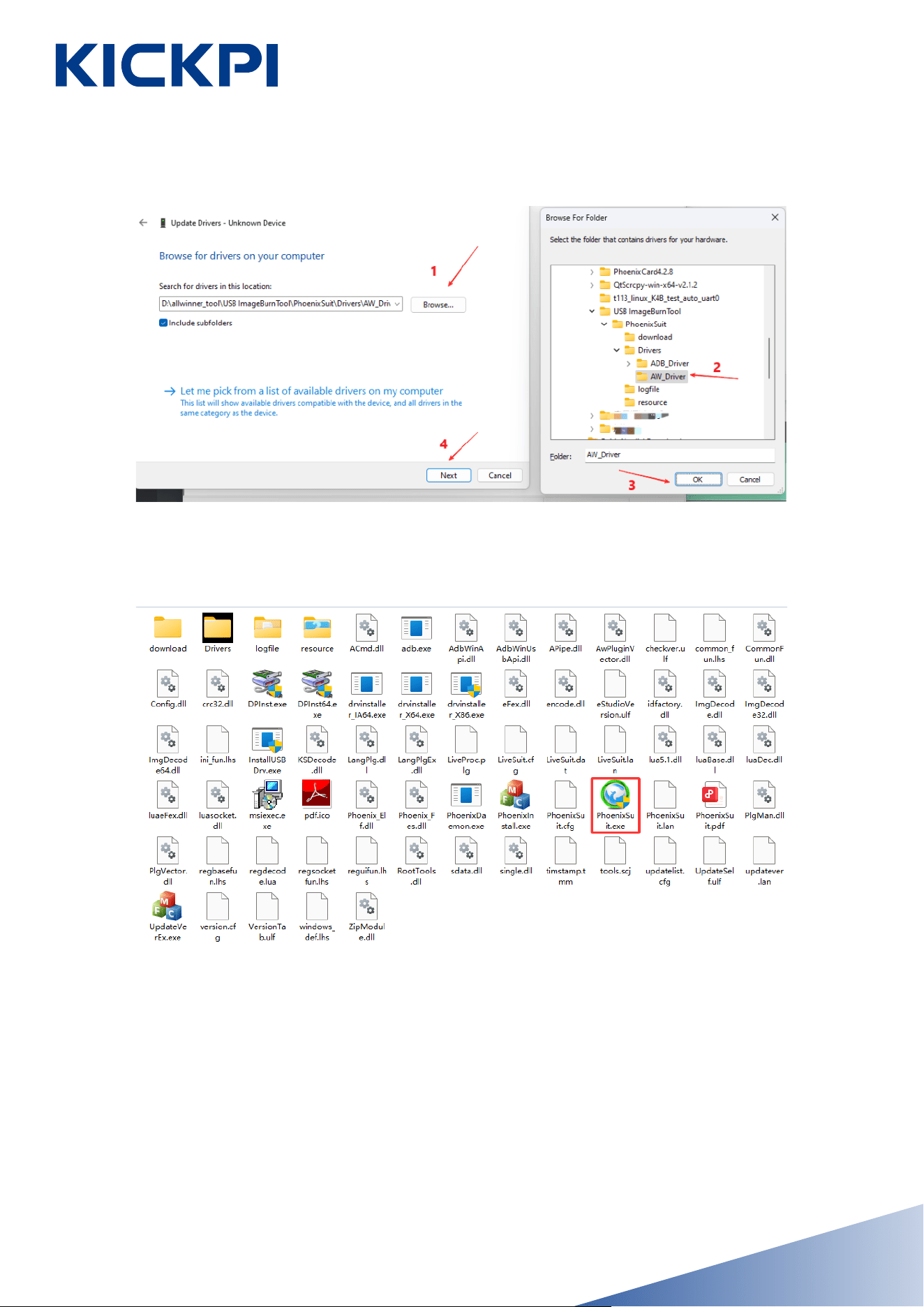
2.Install driver, connect the computer via a USB A - to - C cable, open
the computer's Device Manager, and follow the operations shown in
the diagram. Driver folder path: PhoenixSuit/Drivers/AW_Driver/
www.kickpi.com
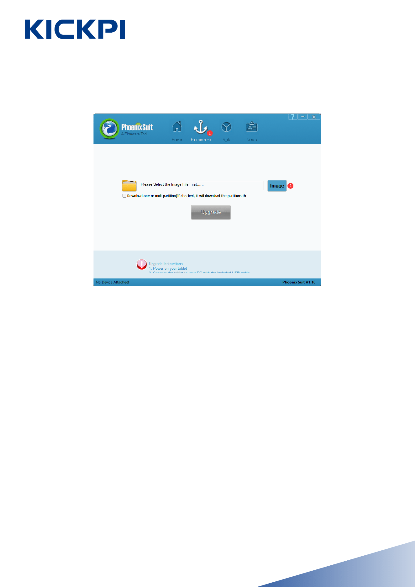
3. Open PhoenixSuit from the extracted folder in Administrator mode.
- 17 -
www.kickpi.com
4. In the installing software, click “firmware” to select the image to be
install (do not click “Upgrade”).
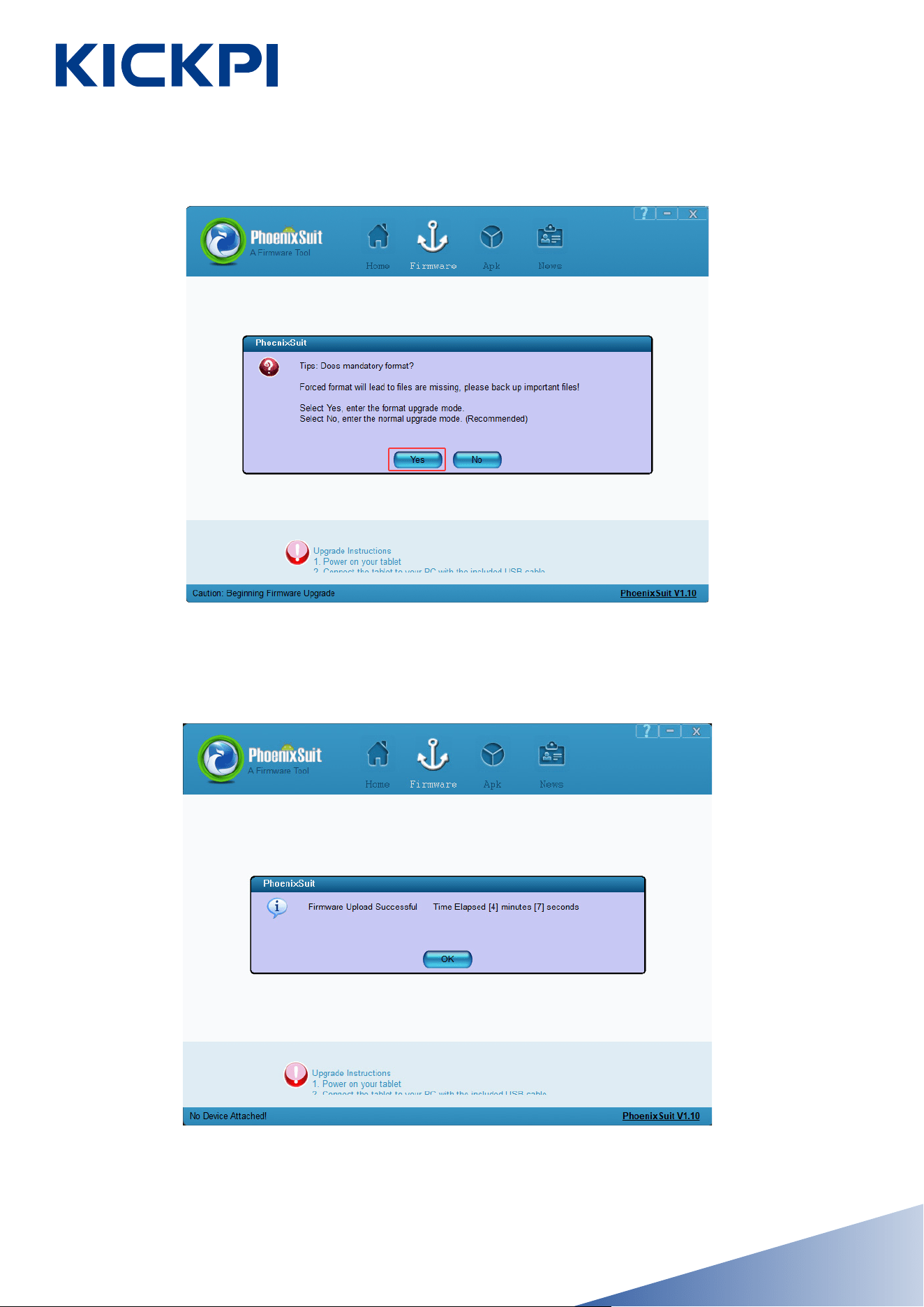
5. Re-enter the installation mode on the development board, connect
the USB, and when the software displays the screen as shown below,
click “Yes” to start installing. Simply wait for the installing to complete
successfully.
Installation Mode:
When the board is powered off, long-press the FEL button on the
bottom side of the board, then connect the power supply. The green
light on the board will stay on, indicating successful entry into Installa-
tion mode.
When the board is powered on, first press and hold the FEL but-
ton,don’t let loose, then press RST button. The green light will stay on,
indicating successful entry into Installation mode.
- 18 -
www.kickpi.com
6. Once the image is installed successfully, the board will restart auto-
matically.
- 19 -

www.kickpi.com
Android Image SD Card Installation
K2B has a SD card slot ( microSD aka. TransFlash or TF ) which can
also serves as a bootable device. In K2B’s boot sequence, SD card has
higher priority, so K2B always try to boot from SD card first, when no
one mounted, K2B then boot from on-board eMMC. Since SoC ven-
dor’s official Tools use terminology SD(microSD) instead of TF, so we
use SD card in this context, TF and SD means the same thing.
With SoC vendor’s tool, we can make 2 types of booting card. SD Boot
Card works like a portable edition OS, e.g.windows PE. We use SD
Boot Card to power device for some maintain and fix purpose. also can
be used to verify your own customization. the second type is SD in-
stallation card. you create this kind of booting card when you try to
use it to install new Image into on-board eMMC. it contains a specific
script to create partition, format FS, copy files to eMMC. Make sure
you understand what you need and create the right SD card.
Preparation
• Hardware: Windows PC/laptop, HDMI Display (optional), USB
TYPE-C cable(some cheap TYPE-C cable only provide current, make
sure use the one capable of data exchange). some users reported when
using double male TYPE-C to TYPE-C cable, installation failed some-
times, when switch to double male USB TYPE-A to TYPE-C, it’s ok.
• Software: Installing tool PhoenixCard, Android image.
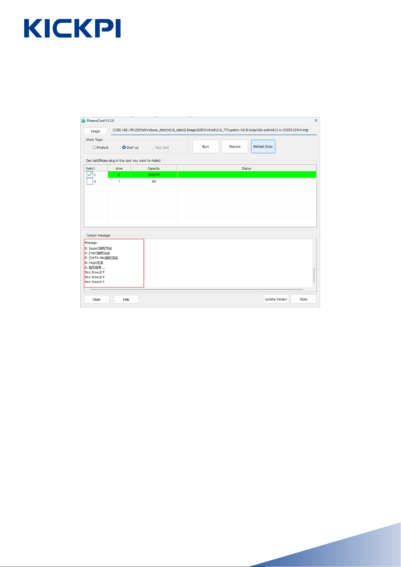
SD Boot Card
When both the eMMC and the SD boot card have system images in-
stalled, the system will boot from the SD card by priority.
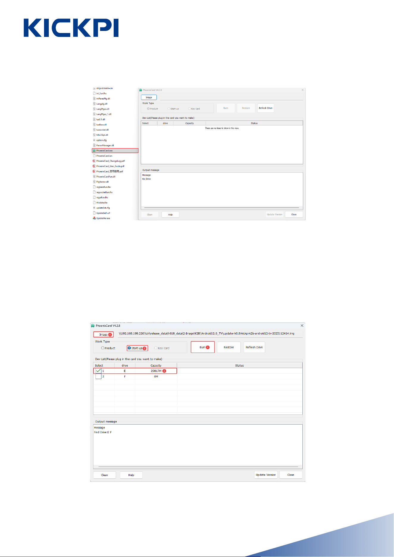
1. Navigate to the PhoenixCard extracted folder and launch Phoenix-
Card.
- 20 -
www.kickpi.com
- 21 -
2. Follow the steps shown in the diagram to flash the downloaded
image onto the SD card.
During the operation, if PhoenixCard prompts to format the SD card,
simply confirm the formatting.
www.kickpi.com
- 22 -
3. The SD boot card is created successfully.
4. Power off the motherboard, insert the SD boot card into the TF card
slot on the motherboard, reconnect the power supply, and wait for the
system desktop to display normally on the monitor
Success: The green LED remains lit, and the blue LED blinks continu-
ously (the blue LED will not light up immediately, please wait patiently).
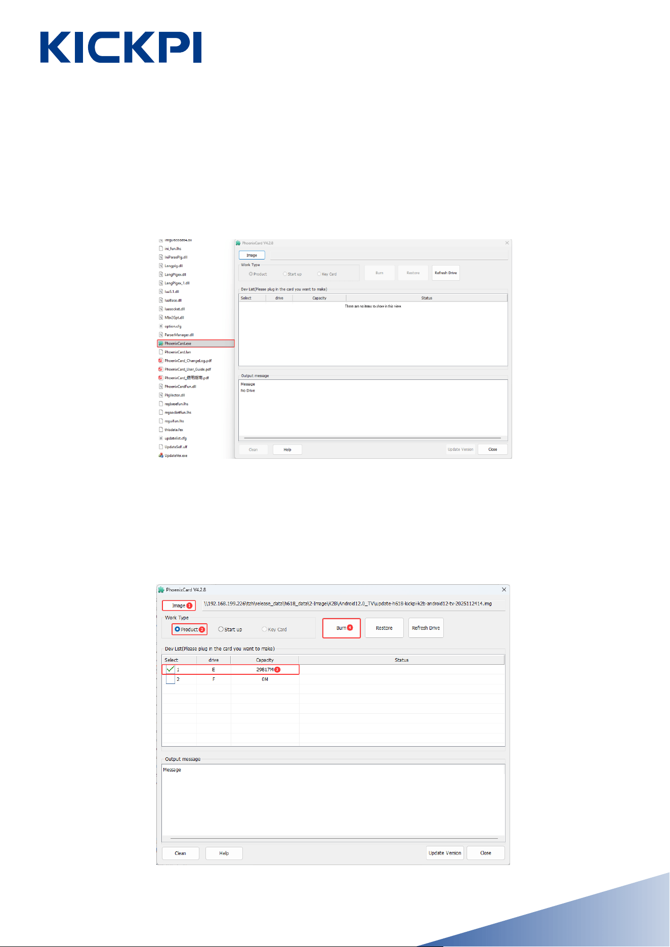
1. Navigate to the PhoenixCard extracted folder and launch Phoenix-
Card.
2. Follow the steps shown in the diagram to flash the downloaded
image onto the SD card.During the operation, if PhoenixCard prompts
to format the SD card, simply confirm the formatting.
www.kickpi.com
�、 SD Installation Card
- 23 -
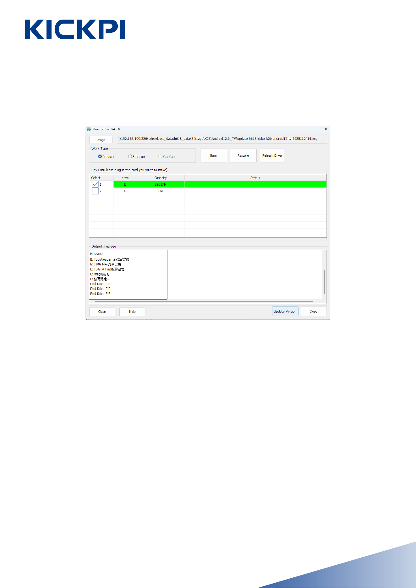
3. The SD boot card is created successfully.
4. Power off the motherboard, insert the SD installation card into the
TF card slot on the motherboard, and wait for the image installation to
complete.
Success: A progress bar will be displayed on the monitor during the
installation; the monitor will turn off upon completion, and both the
green and blue LEDs will be off simultaneously. At this point, remove
the SD card, power the motherboard back on, and wait for the system
to restart.
www.kickpi.com
- 24 -
www.kickpi.com
Ubuntu Image SD Installation
The Ubuntu image currently only supports SD card installing.
Preparation
• Hardware: SD card (recommended capacity larger than 16GB), SD
card reader.
• Software: installing imager tool balenaEtcher, Ubuntu image.
Steps
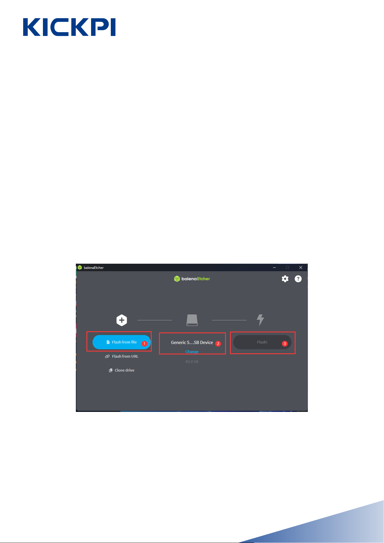
1. Create an SD Boot Card: Insert the SD card into the computer, open
balenaEtcher to write the Linux image.
- 25 -
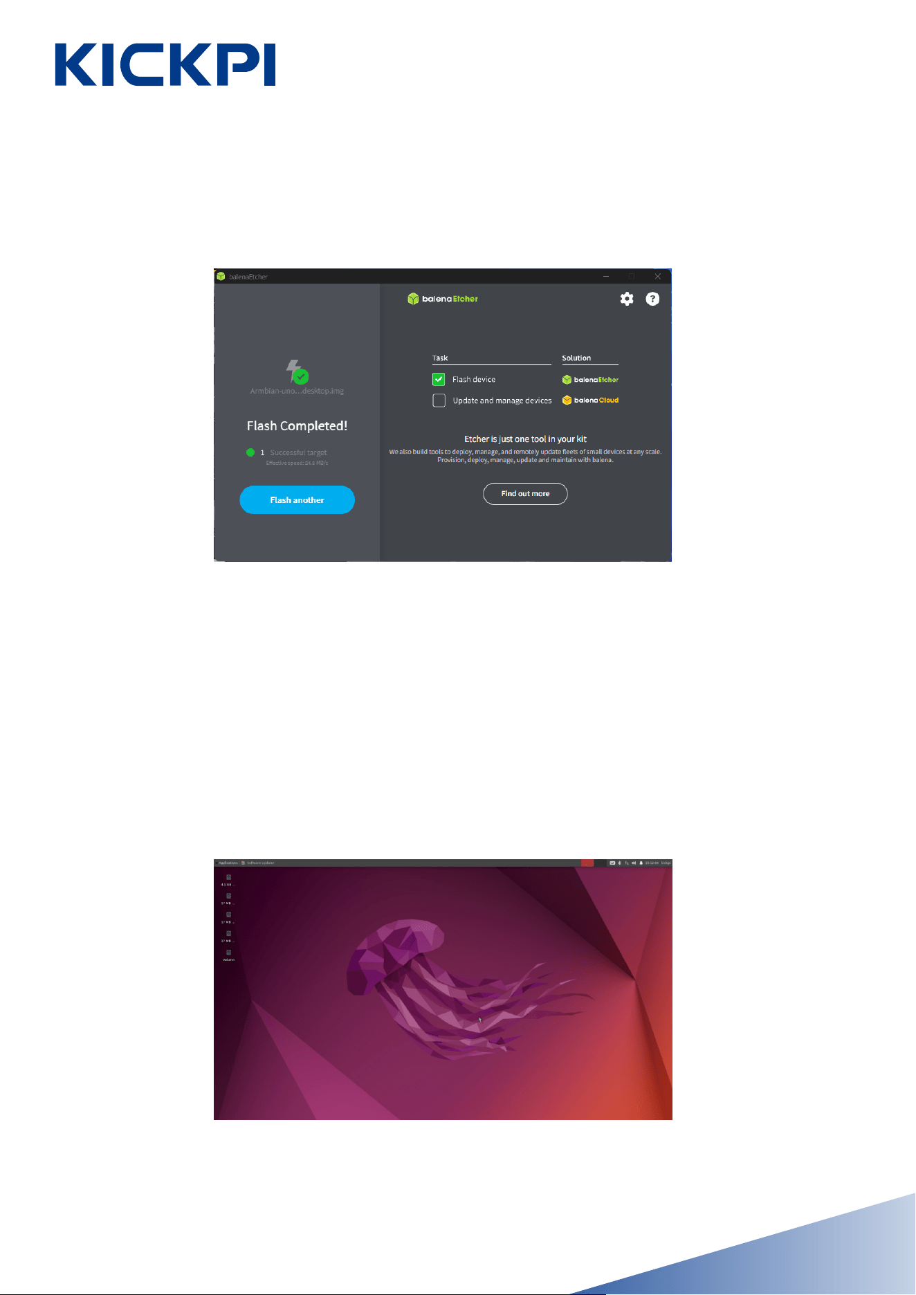
2. After installing is complete, close the imager software.
3. Insert the installed SD card into the development board, power on
the board. The development board will boot from the SD card. Connect
an HDMI monitor to check if the desktop is the newly installed one .
Boot code chooses SD card as the first booting device, then onboard
eMMC in booting.If you only need to boot Ubuntu from the SD card,
you can skip the subsequent installing steps.
www.kickpi.com
- 26 -
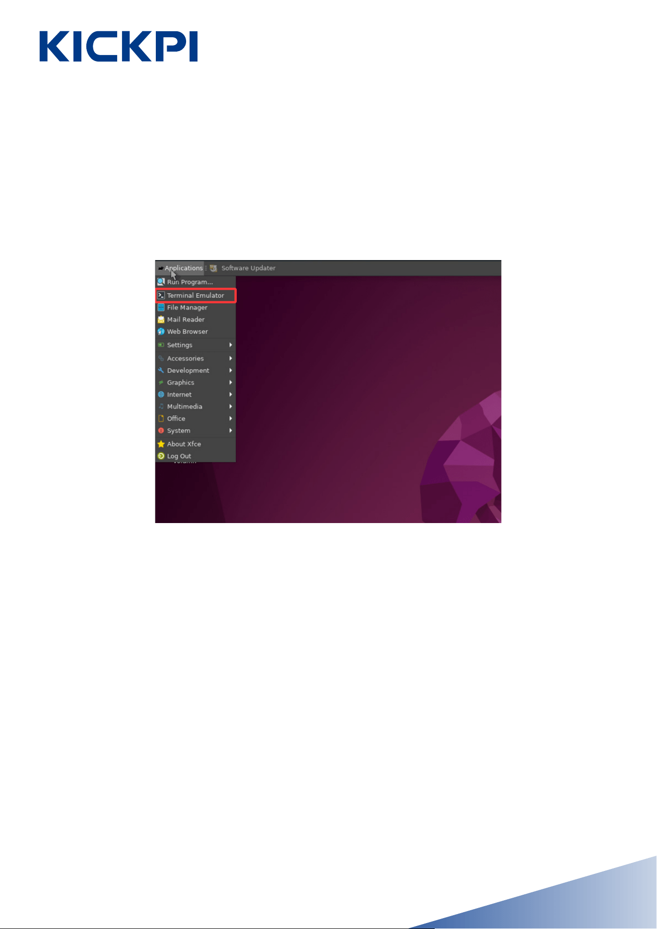
4. Installing Ubuntu system from the SD boot card to onboard eMMC.
• Connect the board to an HDMI monitor, a keyboard, and a mouse,
then open the Terminal Emulator.
www.kickpi.com
- 27 -
• Enter the following command in the Terminal
sudo nand-sata-install 2 1
//Enter the password.
Kickpi
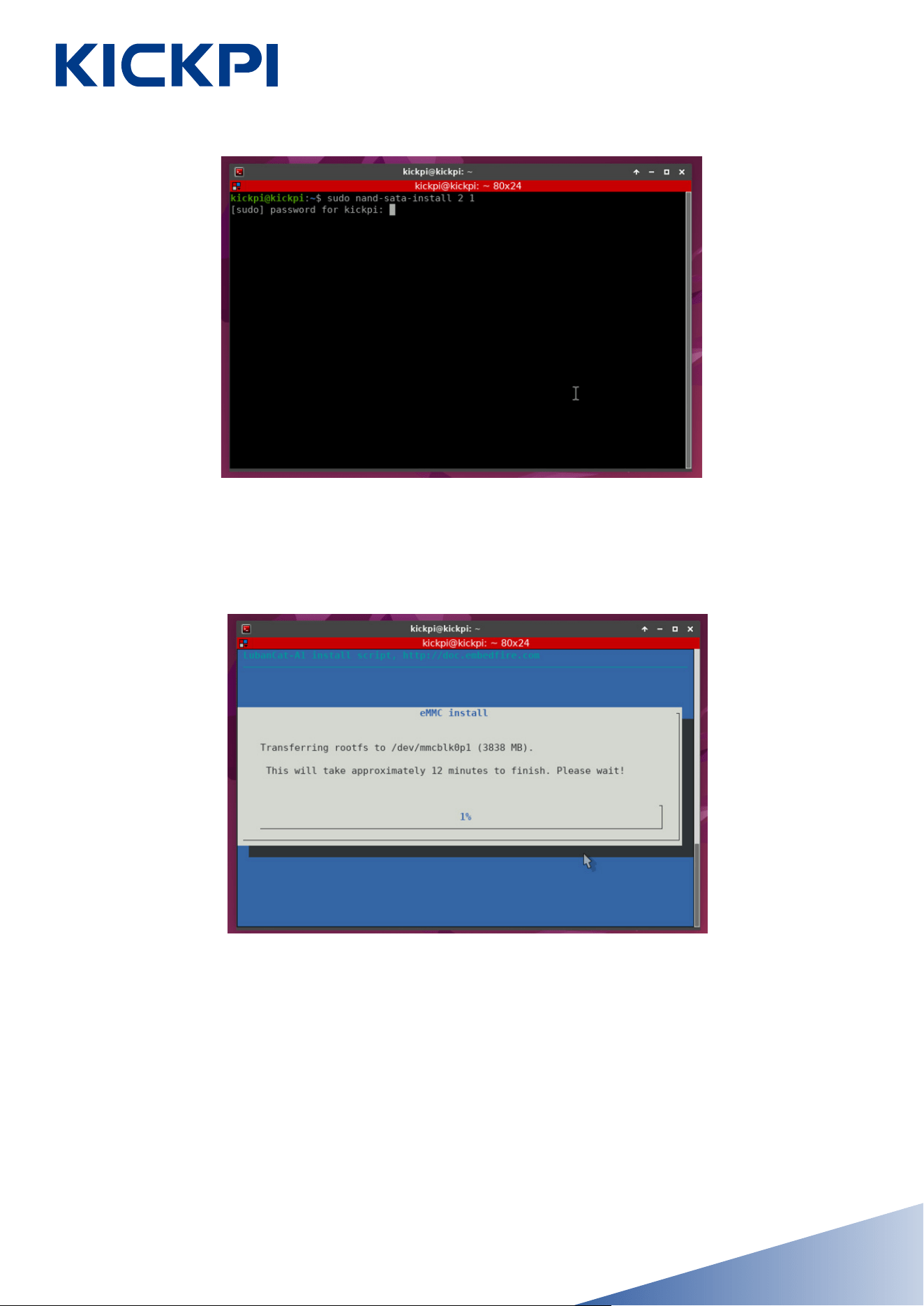
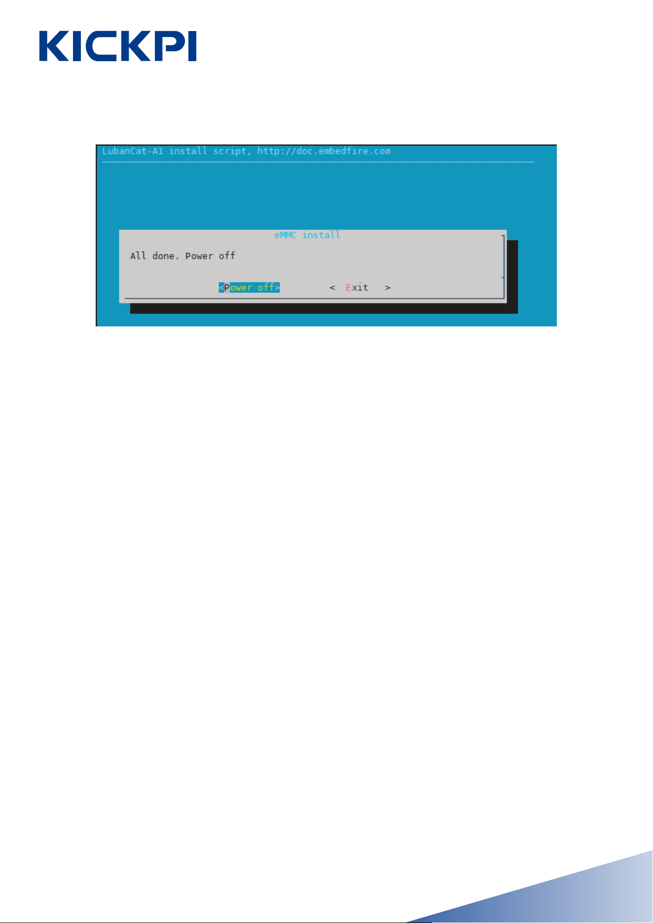
• After the installing is completed, select “Power off”, press the
++enter++ , and wait for the system to restart. Then, power off the
device, remove the SD card, and power it on again to check if the
Ubuntu system has been installed successfully.
• After entering the password, press Enter. The system will automati-
cally start installing process. Wait for the installing to complete.
www.kickpi.com
- 28 -
FCC Warning
This device complies with Part 15 of the FCC Rules. Operation is sub-
ject to the following two conditions:
(1) This device may not cause harmful interference, and (2) this device
must accept any interference received, including interference that may
cause undesired operation.
NOTE 1: This equipment has been tested and found to comply with the
limits for a Class B digital device, pursuant to part 15 of the FCC
Rules. These limits are designed to provide reasonable protection
against harmful interference in a residential installation. This equipment
generates, uses and can radiate radio frequency energy and, if not in-
stalled and used in accordance with the instructions, may cause harm-
ful interference to radio communications. However, there is no guaran-
tee that interference will not occur in a particular installation. If this
equipment does cause harmful interference to radio or television re-
ception, which can be determined by turning the equipment off and on,
the user is encouraged to try to correct the interference by one or
more of the following measures:
www.kickpi.com
- 29 -

- Reorient or relocate the receiving antenna.
- Increase the separation between the equipment and receiver.
-Connect the equipment into an outlet on a circuit different from that
to which the receiver is connected.
-Consult the dealer or an experienced radio/TV technician for help.
NOTE 2: Any changes or modifications to this unit not expressly ap-
proved by the party responsible for compliance could void the user's
authority to operate the equipment.
RF Exposure Statement
To maintain compliance with FCC'S RF Exposure guidelines, This
equipment should be installed and operated with minimum 20cm be-
tween the radiator and your body. This device and its antenna(s) must
not be co-located or operation in conjunction with any other antenna
or transmitter.
www.kickpi.com
- 30 -