MANUAL 14-0330 REV 0 (07/21)
$21.00
MODULAR BASE ELECTRIC TILTING KETTLES
MANUAL SECTION CO
IMPORTANT FOR FUTURE REFERENCE
Please complete this information and retain this
manual for the life of the equipment:
Model #:
___________________________
Serial #:
___________________________
Date Purchased:
_____________________
WARNING
Improper installation, adjustment, alteration, service or maintenance can cause property damage, injury
or death. Read the installation, operating and maintenance instructions thoroughly before installing or
servicing this equipment.
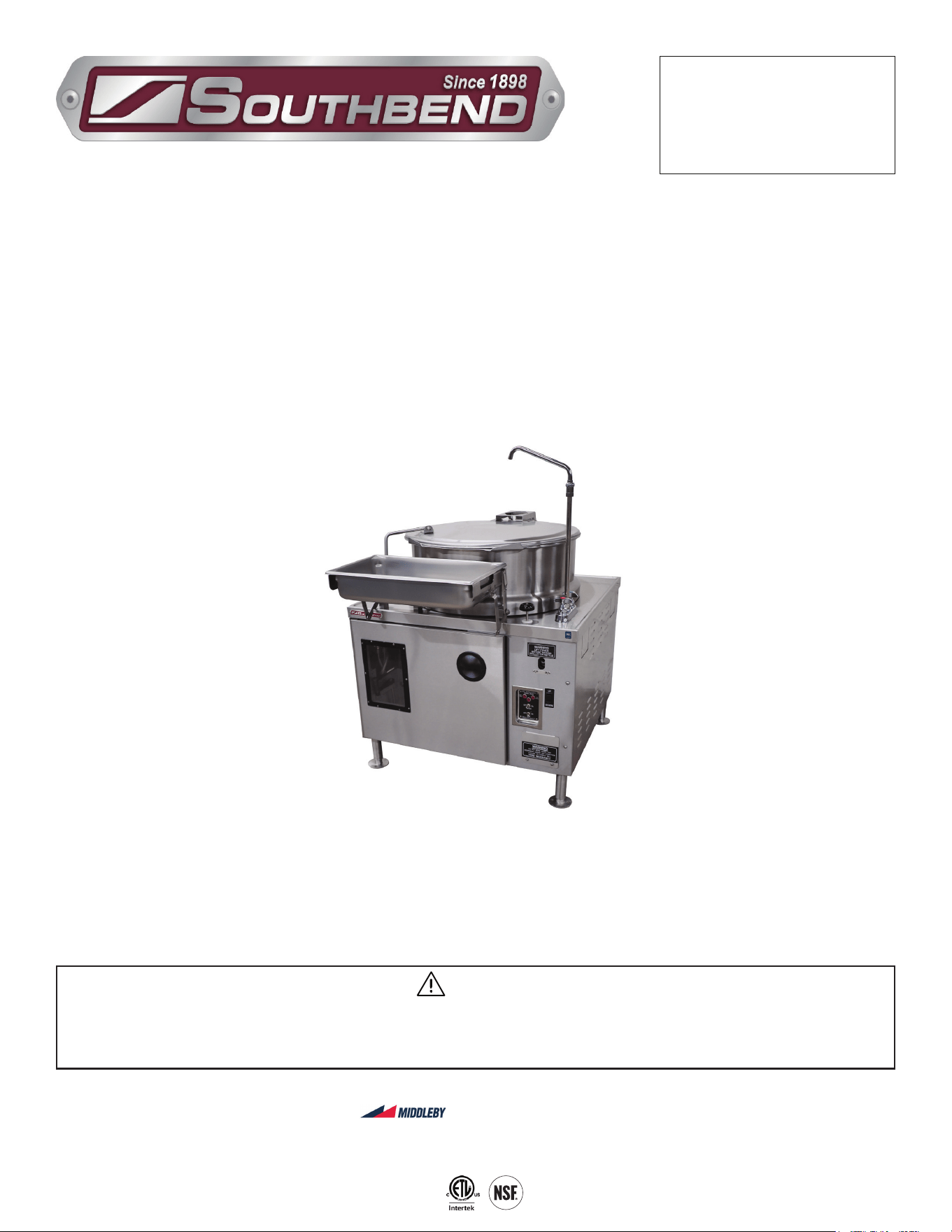
Modular Base Electric Tilting Kettles
MT-25EO-SB & MT-40EO-SB
Installation & Operation Manual
MT-40EO-SB
SOUTHBEND STEAM
A Middleby Company
1100 Old Honeycutt Road Fuquay-Varina, North Carolina 27526 USA
www.southbendnc.com

INSTALLATION & OPERATION MANUAL 14-0330-SB REV 0 (07/21)
PAGE
2
OF 16
Modular Base Electric Tilting Kettles
Your Service Agency’s Address:
Model
Serial number
Kettle installed by
Installation checked by
INSTALLATION & OPERATION MANUAL 14-00330-SB REV 0 (07/21)
PAGE
3
OF 16
Modular Base Electric Tilting Kettles
SAFETY PRECAUTIONS
Copyright © 2021 by Southbend Steam. All rights reserved. Published in the United States of America.
Safety Precautions
WARNING
Improper installation, operation, adjustment, alteration, service or maintenance can cause property damage, injury or death.
Read the installation, operating and maintenance instructions thoroughly before installing, operating or servicing this equipment.
NOTICE
This manual should be retained for future reference.
NOTICE
This product is intended for commercial use only. NOT FOR HOUSEHOLD USE.
WARNING
This is the safety alert symbol. It is used to alert you to potential personal injury hazards. Obey all safety messages
that follow this symbol to avoid possible injury or death.
WARNING
FOR YOUR SAFETY:
Do not store or use gasoline or other ammable vapors or liquids in the vicinity of this or any other appliance.
IMPORTANT
PURCHASER: Instructions to be followed in the event the operator of this appliance smells gas must be posted in a
prominent location. This information shall be obtained by consulting the local gas supplier.
The information contained in this manual is important for the proper installation, use, and maintenance of this kettle.
Adherence to these procedures and instruc- tions will result in satisfactory baking results and long, trou- ble free service.
Please read this manual carefully and retain it for future reference.
ERRORS: Descriptive, typographic or pictorial errors are subject to correction. Specications are subject to change
without notice.
Before installing and operating this equipment, be sure everyone involved in its operation is fully trained and aware of
precautions. Accidents and problems can be caused by failure to follow fundamental rules and precautions.
The following symbols, found throughout this manual, alert you to potentially dangerous conditions to the operator,
service personnel, or to the equipment.
CAUTION
WARNING
NOTICE
This symbol warns of immediate hazards that will result in severe injury or death.
This symbol refers to a potential hazard or unsafe practice that could result in injury or death.
This symbol refers to a potential hazard or unsafe practice that could result in injury, product
damage, or property damage.
This symbol refers to information that needs special attention or must be fully
understood, even though not dangerous.
DANGER
IMPORTANT NOTES FOR INSTALLATION AND OPERATION

INSTALLATION & OPERATION MANUAL 14-0330-SB REV 0 (07/21)
PAGE
4
OF 16
Modular Base Electric Tilting Kettles
RETAIN THIS MANUAL FOR FUTURE REFERENCE.
Table of Contents
Important Notes For Installation and Operation .................................................................... 3
Service Connections ............................................................................................................. 5
Introduction ........................................................................................................................... 6
Operation .............................................................................................................................. 7
Maintenance ......................................................................................................................... 12
Table of Contents
INSTALLATION & OPERATION MANUAL 14-00330-SB REV 0 (07/21)
PAGE
5
OF 16
Modular Base Electric Tilting Kettles
SERVICE CONNECTIONS
Service Connections
As continued product improvement is a policy of Southbend Steam, specications are subject to changge without notice.
WATER SUPPLY AND DRAIN SPECIFICATIONS
Good quality water feed is the responsibility of the owner. Water quality must be within the following general guidelines.
TDS: 40-125 ppm Hardness: 35-100 ppm pH: 7.0 - 8.5 Silica: <13 ppm Chlorides: <25 ppm Chlorine: <0.2 ppm Chloramine: <0.2 ppm
The best defense against poor water quality is a water treatment system designed to meet your water quality conditions.
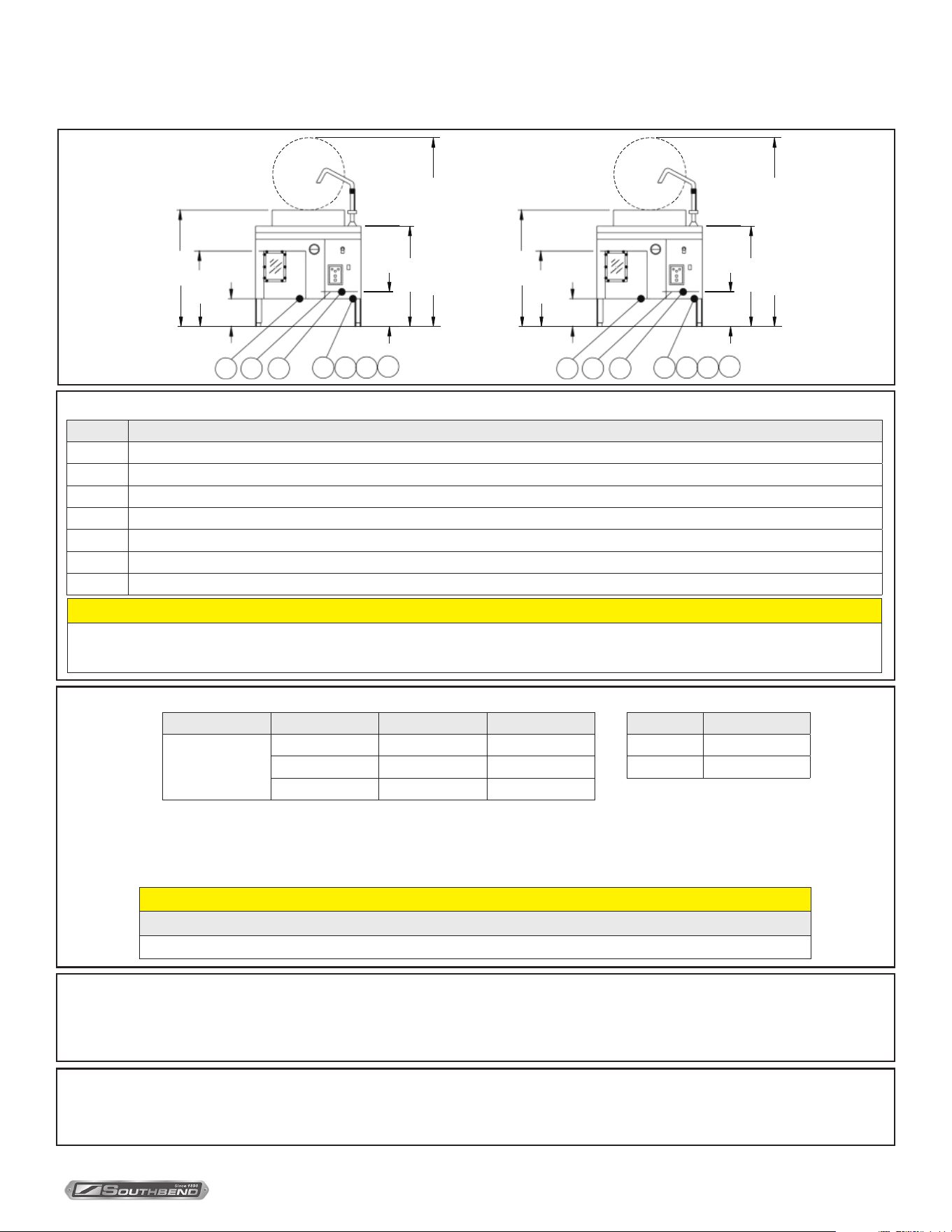
DIMENSIONS ARE
IN INCHES [MM]
SERVICE CONNECTIONS
SYMBOL DESCRIPTION
EP Power Supply - Use wire suitable for at least 90°C, Nominal amps per line wire at 24 KW:
EC Electrical Controls - 115 Volts Ac, 60Hz, 40 watts, 1/2” (13mm) conduit connection or equivalent. Use wire suitable for at least 90°C. Draws less than 1 AMP with power lift.
D Drain - Pipe full 2” (51mm) NPT to floor drain. DO NOT MAKE SOLID CONNECTION TO FLOOR DRAIN. PVC and CPVC are not acceptable materials for drains.
HWK Hot Water - 3/8” (10mm) NPT Female for Hot Water to Kettle Faucet (See Note 3)
CWK Cold Water - 3/8” (10mm) NPT Female for Cold Water to Kettle Faucet (See Note 3)
CWB Cold Water - 3/8” (10mm) NPT Female for Cold Water to Boiler. Water may be filtered (See Note 3).
CWC Cold Water - 3/8” (10mm) NPT Female for Cold Water Condenser (See Note 3)
Model Shipping Weight
MT-25EO-SB 410 lbs (186 kg)
MT-40EO-SB 430 lbs (195 kg)
1. Recess area for kettle draw-off must be kept free of all piping and connections.
2. The only available space to supply utilities to the unit is the 6” (152mm) height between the floor and the cabinet.
3. Water pressure max 50 PSI (3.5kg/cm2) and min 25 PSI (1.8kg/cm2).
ELECTRICAL CHARACTERISTICS AND WEIGHT INFORMATION
NOTES
CAUTION
REMOTE KETTLE OPERATION
If this boiler is feeding a remote kettle that will be more than 5 feet (1.5 meters) away, consult factory before ordering.
Model Volts Phase Amps
MT-25EO-SB
MT-40EO-SB
208 3 66.6
240 3 57.7
480 3 28.8
05]12 [3
65]38 [9
3321 [5 ]
52]13.88[3
13]16.25 [4
38]33 [8
128 [7 1]
65.5[1664]MAXIMUM HEIGHT
15 [381]
D
CWB
CWKCWC HWK
SeeNote1
9[228]
2.88 [73]
2.5[64]
EC EP
11.5
[292]
1.75 [45]
4.31 [110]
15
2.88 [73]
[381]
36 [914]
6.38
[162]
6
[152]
SeeNote
1
7
[179]
DECEP
HWKCWK CWB
CWC
05]12 [3
65]38 [9
3321 [5 ]
52]13.88[3
13]16.25 [4
38]33 [8
128 [7 1]
65.5[1664]MAXIMUM HEIGHT
15 [381]
D
CWB
CWKCWC HWK
SeeNote1
9[228]
2.88 [73]
2.5[64]
EC EP
11.5
[292]
1.75 [45]
4.31 [110]
15
2.88 [73]
[381]
36 [914]
6.38
[162]
6
[152]
SeeNote
1
7
[179]
DECEP
HWKCWK CWB
CWC
Terry System Cartridge Changes / Installation – “2-3 gallons of water MUST be purged at each cartridge change or new installation prior to
water supply being fed to the steamer. Failure to do so can result in component damage within the steamer which is not covered under warranty.
For additional guidance on proper installation, refer to install documentation provided with each Terry System and Replacement Cartridge Set.”
DISCLAIMER
CAUTION
Before connecting water to this unit, have water supply analyzed to make sure hardness i no greater than 2.0 grains and pH level is within the range of 7.0-8.5. Water
which fails to meet these standards should be treated by installing a filter or conditioner. EQUIPMENT FAILURE CAUSED BY INADEQUATE WATER QUALITY IS
NOT COVERED UNDER WARRANTY.

INSTALLATION & OPERATION MANUAL 14-0330-SB REV 0 (07/21)
PAGE
6
OF 16
Modular Base Electric Tilting Kettles
Description
Southbend Steam model MT-25EO-SB (25-gallon) and MT-40EO-SB (40-gallon) are self-contained tilting electric
steam jacketed kettles. Each kettle has a jacket of double-wall con- struction forming a sealed reservoir around the
lower two-thirds of the kettle.
The stainless steel kettle is enclosed in a cabinet base containing a 24 kW electrically powered boiler for kettle operation.
Basic Functioning
The kettle becomes operational when the power switch is placed in the ON position. At this point, the boiler reservoir
begins to ll with water automatically until the water level reaches a factory preset, high water level. At the high water
level, incoming water ow is shut o.
Once the water level is suciently above the heating elements, the heater rest switch is momentarily placed in the ON
position. The action releases closing contactors to heating elements.
After steam pressure builds up to proper operating pressure, the steam control valve on the cabinet top can then be
manually operated. This open valve allows steam to ow into the kettle jacket, heating both the kettle and contents. As
water level drops due to steam conversion, the automatic water level control system opens and closes the incoming water
valve to maintain constant water level. If the level control system fails, and automatic low water cut o switch turns o
power to heating elements.
Service
Required service, both repair, replacement, and adjustment is explained in Adjustments section of this manual. Other
service help can be found in the Trouble Shooting and Maintenance sections of this manual. Should repairs be required,
a network of Authorized Service Agents is available to assist with prompt service. A current list of Authorized Service
Agencies may be obtained by contacting Southbend Steam direct of going on our website http://www. mi.com.
The model and serial number must be referenced when corresponding with Southbend Steam. These numbers can be
found on the data plate located on the upright frame behind the cabinet base door. If you require further assistance in
obtaining these numbers, please contact us directly.
INTRODUCTION
Introduction
INSTALLATION & OPERATION MANUAL 14-00330-SB REV 0 (07/21)
PAGE
7
OF 16
Modular Base Electric Tilting Kettles
OPERATION
Operating Instructions
Start-Up
Before beginning start-up procedure, ensure that power
and water supplies are available. Also, ensure that the
kettle drain is functional.
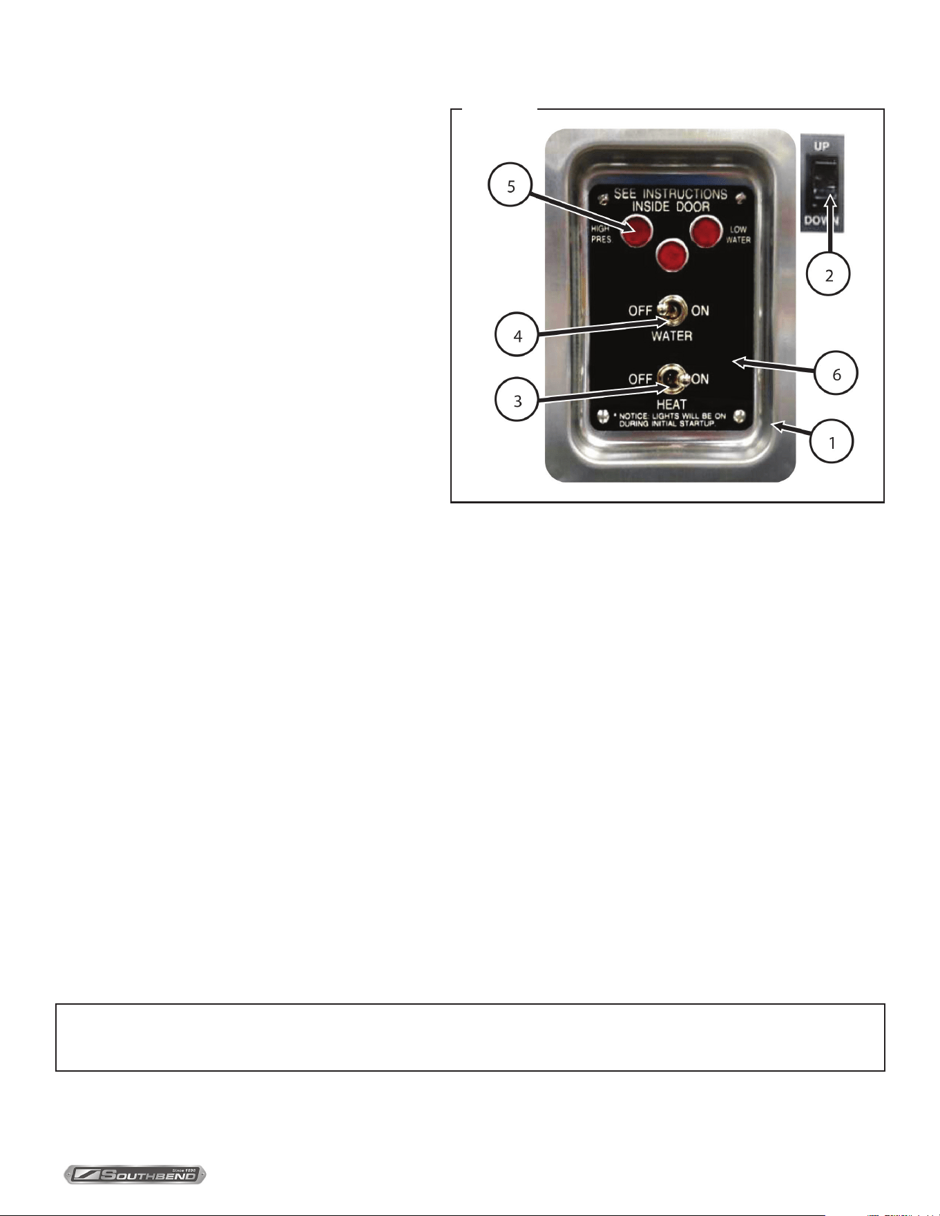
Control Panel
1. DISH
2. SWITCH, UP/DOWN (optional power tilt)
3. HEAT SWITCH
4. SWITCH, ON/OFF
5. LIGHT
6. SWITCH PLATE
Operating Instructions for Steam Boiler
First be sure to check that
1. Water switch is in the OFF position.
2. Water supply valve is open.
3. Electricity is connected to all units.
4. Then proceed with daily operating procedures.
Daily Operating Procedure:
1. Flip water switch from OFF to ON.
2. Wait 5-10 minutes for water to ll in steam boiler (bullseye sight glass should be visible as half full.)
3. Flip heat switch from ON to OFF and release back to on when the low water light goes o. Red indicator light will
come on. (This is necessary to manually reset the unit.)
Daily Shut Down
1. STEP 1 - Press water switch OFF. This will drain the steam boiler.
2. STEP 2 - After steam boiler has completely drained repeat.
3. STEPS 1 & 2 of daily operating procedure. (Water to remain in steam boiler until next daily use).
NOTICE
This shut-o procedure must be performed daily to ensure proper functioning of the kettle.
OPERATION
Figure 1
INSTALLATION & OPERATION MANUAL 14-0330-SB REV 0 (07/21)
PAGE
8
OF 16
Modular Base Electric Tilting Kettles OPERATION
Cooking
1. Check pressure to ensure that boiler is up to operational pressure of 10-12 PSI (0.7-0.8kg/cm
2
).
2. Check that draw-o valve is tightly closed by turning it
clockwise.
3. Place solid disc or perforated disc in drain opening inside
kettle.
Figure 2
4. Fill kettle to desired level with food to be cooked or water
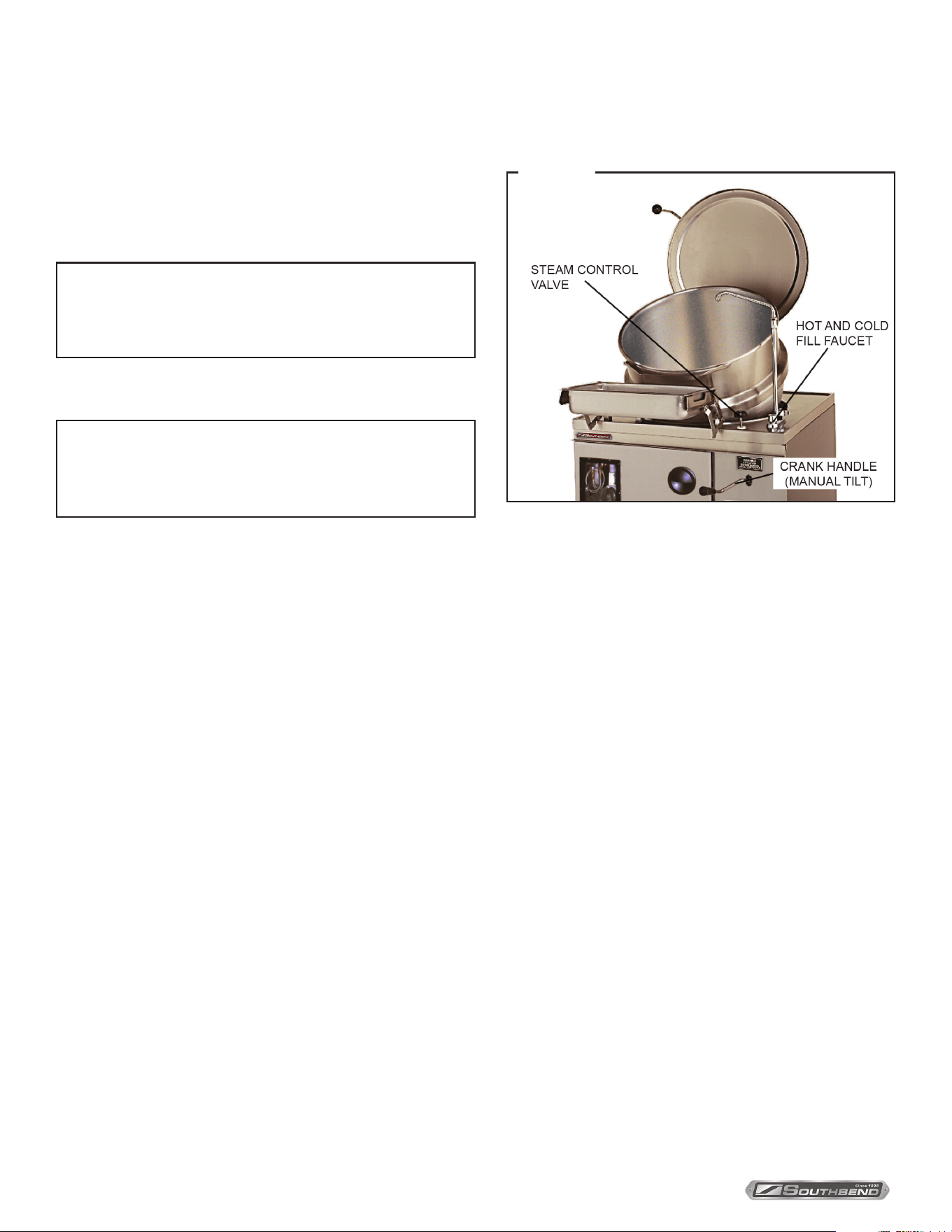
from hot and cold ll faucet. See “Figure 2”.
5. Turn kettle steam control valve counterclockwise to full ON position for faster results. See “Figure 2”.
NOTE: The volume of steam going into the kettle jacket can be controlled at any time by adjusting the kettle steam control
valve in either direction.
6. When food is cooked, turn steam control valve clockwise to stop steam ow. Remove food immediately to prevent
over cooking.
7. Prior to removing foods from kettle, the pan support should be placed in a position to establish a rm support for
receiving pan.
NOTICE
Use solid disc if liquid is to be retained; use perforated
disc if liquid is to be discarded.
NOTICE
Refer to Cooking Guide for cooking procedures that
address individual food products.
INSTALLATION & OPERATION MANUAL 14-00330-SB REV 0 (07/21)
PAGE
9
OF 16
Modular Base Electric Tilting Kettles OPERATION
NOTICE
When removing pan support, reverse the above installation sequence.
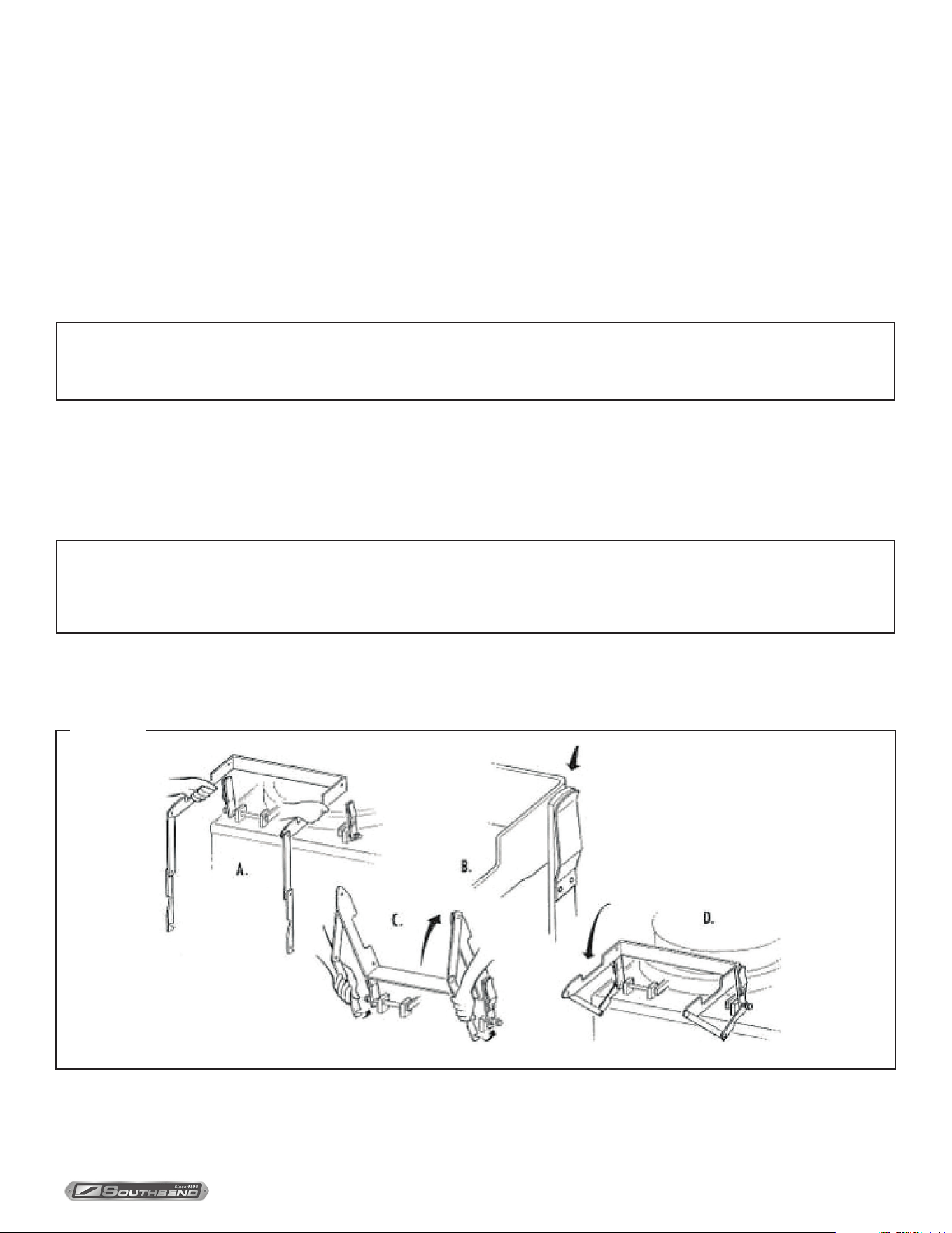
Install Pan Support
1. With both hands, hold pan support in front of upright supports. Cutouts on each side must be facing upward and
jointed links must be allowed to fall free.
2. Place stud – located on left hand upright support – into hole in left hand side of pan support. After engaging left hand
side, push right hand side in until spring loaded pin on right hand side of pan support engages hole in pan support.
3. Rotate pan support up to near vertical position. Shifts both hands to lowermost links and simultaneously engage their
slotted ends to studs at base of each upright support.
4. Allow pan support to drop back to horizontal position where it will automatically lock. Pan support should now be rmly
in place.
5. To tilt kettle, remove crank handle from its stored position inside of cabinet door.
6. Insert crank handle into tilt kettle mechanism.
7. Pour out nished product from kettle by turning crank handle clockwise to tilt kettle. Liquids may be drawn o through
draw-o valve to a stock pot. Lower kettle by turning crank handle counterclockwise.
Install Pan Support
1. With both hands, hold pan support in front of upright supports. Cutouts on each side must be facing upward and
jointed links must be allowed to fall free.
2. Place stud – located on left hand upright support – into hole in left hand side of pan support. After engaging left hand
side, push right hand side in until spring loaded pin on right hand side of pan support engages hole in pan support.
3. Rotate pan support up to near vertical position. Shifts both hands to lowermost links and simultaneously engage their
slotted ends to studs at base of each upright support.
4. Allow pan support to drop back to horizontal position where it will automatically lock. Pan support should now be rmly
in place.
8. Add water to kettle for cleaning purposes.
9. Wash kettle thoroughly, see Daily Cleaning Instructions.
NOTICE
Crank handle turning may be stopped at any point without kettle setting back.
Full 110° tilt is obtained in approximately 42 turns of the crank.
Figure 3

INSTALLATION & OPERATION MANUAL 14-0330-SB REV 0 (07/21)
PAGE
10
OF 16
Modular Base Electric Tilting Kettles OPERATION
Cooking Facts for Steam Jacketed Kettles
A Steam Jacketed Kettle is a stainless steel kettle jacketed or encapsulated by a second outer kettle, creating a space
between the two kettles. Cooking is achieved by allowing steam to ow within this space. The jacket or outer kettle usually
covers 2/3 of the inner kettle, although some kettles are fully jacketed
The steam owing in the space between the kettles con- denses on the cold inner kettle wall and releases heat through
the wall to the food in the kettle. The condensate drains to the bottom of the kettle and is released through a steam trap
without any loss or variation in steam pressure. The amount of steam allowed to ow Into the Jacket controls the heat of
the kettle. In use, the Steam Jacketed Kettle provides consistent heat distribution and is energy ecient using steam only
to maintain pressure, unlike top of the range cooking in which energy (gas or electricity) is used during the entire cooking
process.
Steam Jacketed Kettles can sauté, simmer, or boil a wide variety of products, such as soups, gravies, sauces, pasta,
stews, mixed casserole type dishes, vegetables, shellsh, cereals, hot beverages, and puddings. A Steam Jacketed
Kettle will not burn foods. However, foods that caramelize at relatively low temperatures, such as eggs and milk based
products, will coat and cook onto the sides of the kettle. Care should be taken to use the smallest ow of steam, to lessen
the possibility of scorching these products. To achieve this, allow products to come up to desired temperature, stirring
frequently, then turn o steam ow and gradually turn on a small ow of steam - just enough to allow food to cook.
Steam Jacketed Kettles eliminate much range top cooking and greatly reduce the number of pots and pans re- quired.
Because they are made of stainless steel, they are durable, non-porous and easy to clean.
• Estimate actual cooking capacity of Steam Jacketed Kettles at 3/4 of its volume, to allow stirring without spillage.
• Plan an adequate drain arrangement. This is very important for ease of use and to minimize wet oors. A grated gutter
type drain located in front of the kettles is preferred as it eliminates the hazards of tripping over a curb or stumbling
into a recessed drain area.
• Locate a source of water (swivel faucet or exible hose type) near the kettle to facilitate lling and cleaning.
• Cover products whenever possible to save energy. Covered water boils 25 to 30% faster.
• Use the tangent draw o valve to drain o products from the kettle such as sauces and puddings, or cooking liquids
that are being discarded (as in the case of the water used to cook pasta)
• Remove the tangent draw o valve after each use for cleaning, using a brush to clean draw o as bacteria will readily
multiply in this area if it is not thoroughly cleaned.
• Use the optional solid kettle disk when product is not going to be dispensed through the draw o valve, and the
perforated disk when draining o liquids through the draw o valve and retaining the solid product in the kettle.
INSTALLATION & OPERATION MANUAL 14-00330-SB REV 0 (07/21)
PAGE
11
OF 16
Modular Base Electric Tilting Kettles
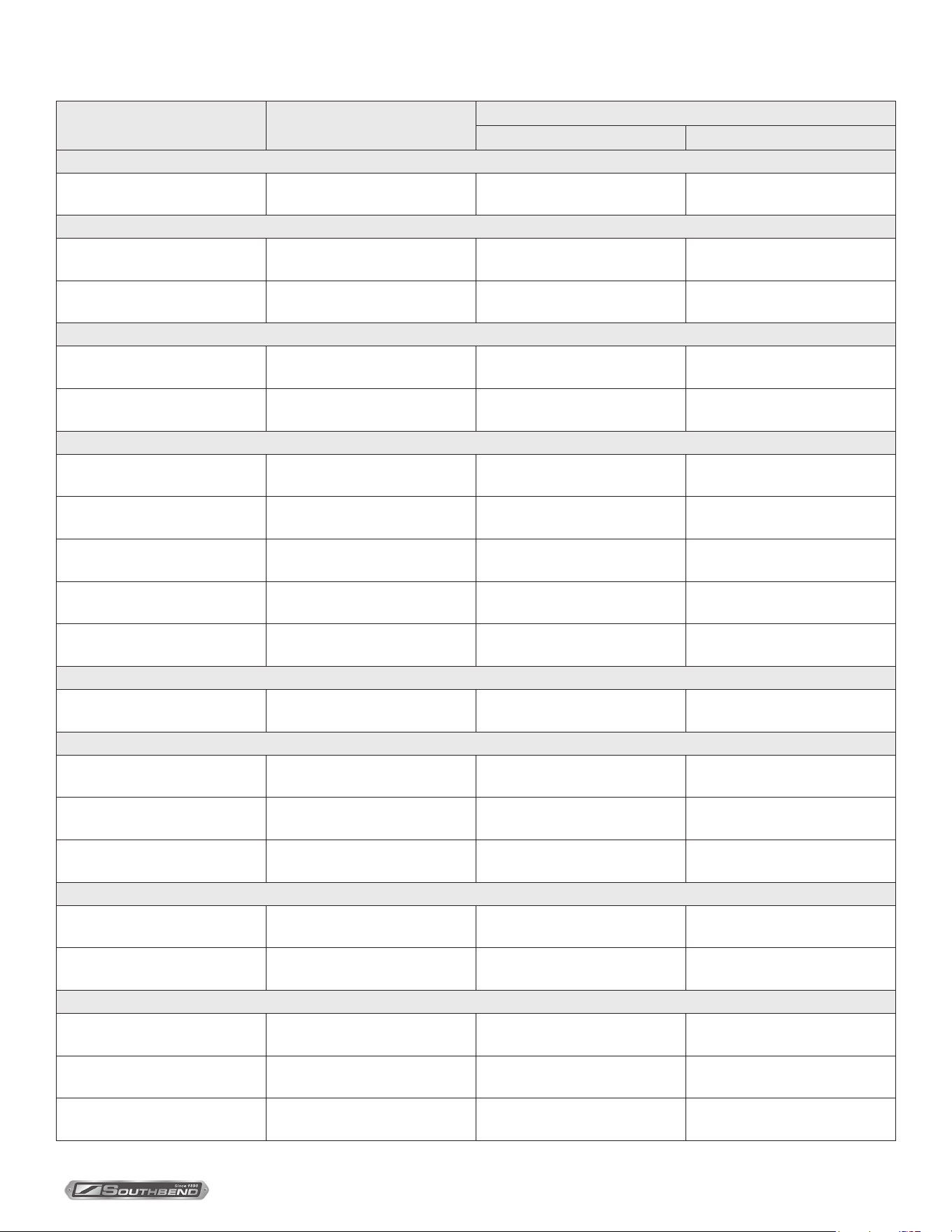
ITEM COOKED PORTION SIZE
KETTLE SIZE
25 gallon (95 liters) 40 gallon (150 liters)
BEVERAGES
Cocoa or Coee 6 oz or 3/4 cup (180 ml.)
Yield: 20 gal. (75 l.)
Portions = 425
Yield: 35 gal. (132 l.)
Portions = 745
BREAKFAST FOODS
Cereal 6 oz or 3/4 cup (180 ml.)
Amt. Raw: 20# (9 kg.)
Portion = 270
Amt. Raw: 36 # (16.3 kg)
Portion = 480
Scrambled Eggs 4 oz or 2 eggs each (115 g.)
Eggs: 90 dz. 18 gal. (120 l.)
Portions = 540
Eggs: 160 dz., 32 gal. (166.5 l.)
Portions = 960
DESSERTS
Cornstarch Pudding 4 oz. or 1/2 cup (120 ml.)
Yield: 17 gal. (64.3 l.)
Portions = 545
Yield: 30 gal. (113.5l.)
Portions = 960
Gelatin 4 oz. or 1/2 cup (120 g.)
Yield: 20 gal. (75 l.)
Portions = 640
Yield: 35 gal. (132 l.)
Portions = 1120
MAIN ENTREES *
Macaroni, Beef and Tomato 6 oz. or 3/4 cup (170 g.)
Yield: 17 gal. (65 l.)
Portions = 360
Yield: 30 gal. (113 l.)
Portions = 640
Baked Beans 5 oz. or 2/3 cup (140 g.)
Yield: 20 gal. (75 l.)
Portions = 500
Yield: 32 gal. (120 l.)
Portions = 800
Beef Stew 8 oz. or 1 cup (225 g.)
Yield: 17 gal. (65 l.)
Portions = 270
Yield: 30 gal. (113 l.)
Portions = 480
Macaroni and Cheese 5 oz. or 2/3 cup (140 g.)
Yield: 17 gal. (64 l.)
Portions = 425
Yield: 30 gal. (113 l.)
Portions = 750
Turkey A La King 4 oz. or 1/2 cup (115 g.)
Yield: 17 gal. (64 l.)
Portions = 545
Yield: 30 gal. (113 l.)
Portions = 960
MISCELLANEOUS
Gravy/Sauce 2 oz. or 3/4 cup (60 ml.)
Yield: 20 gal. (75 l.)
Portions = 1200
Yield: 35 gal. (132 l.)
Portions = 2000
MACARONI AND RICE
Noodles 4 oz. or 3/4 cup (115 g.)
Amt. Raw: 20 gal. (9kg.)
Portions = 220
Amt. Raw: 35 # (15.8kg.)
Portions = 385
Rice 3 oz. or 1/2 cup (85 g.)
Amt. Raw: 20 gal. (9 kg.)
Portions = 320
Amt. Raw: 35 # (15.8 kg.)
Portions = 560
Spaghetti or Macaroni 4 oz. or 3/4 cup (115 g.)
Yield: 20 gal. (9 kg.)
Portions = 320
Amt. Raw: 35 # (15.8kg.)
Portions = 385
SOUPS
Basic Cream Soup 6 oz. or 3/4 cup (180 ml.)
Yield: 20 gal. (75 l.)
Portions = 400
Yield: 35 gal. (132 l.)
Portions = 700
Broth Type Soup 8 oz. or 1 cup (240 ml.)
Yield: 20 gal. (75 l.)
Portions = 325
Yield: 35 gal. (132 l.)
Portions = 560
VEGETABLES
Fresh 4 oz. or 1/2 cup (115 g.)
Amt.Raw: 80#. (36.3kg.)
Portions = 335
Amt. Raw:120 # (54.4 kg.)
Portions = 500
Frozen Loose Pack 4 oz. or 1/2 cup (115 g.)
No. Of Packages: 50
Portions = 550
No. Of Packages: 80
Portions = 880
Frozen Solid Pack 4 oz. or 1/2 cup (115 g.)
No. Of Packages: 25
Portions = 275
No. Of Packages: 40
Portions = 440
* All main entree gures are given in terms of raw ingredients
Cooking Chart
INSTALLATION & OPERATION MANUAL 14-0330-SB REV 0 (07/21)
PAGE
12
OF 16
Modular Base Electric Tilting Kettles
10. Remove swivel drain and its strainer. Wash, rinse and replace.
Weekly Cleaning
In addition to the daily cleaning it is necessary to clean the air intakes
on a weekly basis. Air intakes provide necessary cooling air to the
internal components. They are generally located on the rear and
sides of the equipment.
Tilting Mechanism Lubrication
Lubrication of the tilting mechanism is the only required preventive maintenance other than daily cleaning.
1. Inspect the screw of the tilting mechanism annually for adequate lubrication.
2. If screw appears “dry”, apply good grade bearing grease directly on the threads so that the threads appear to be barely damp.
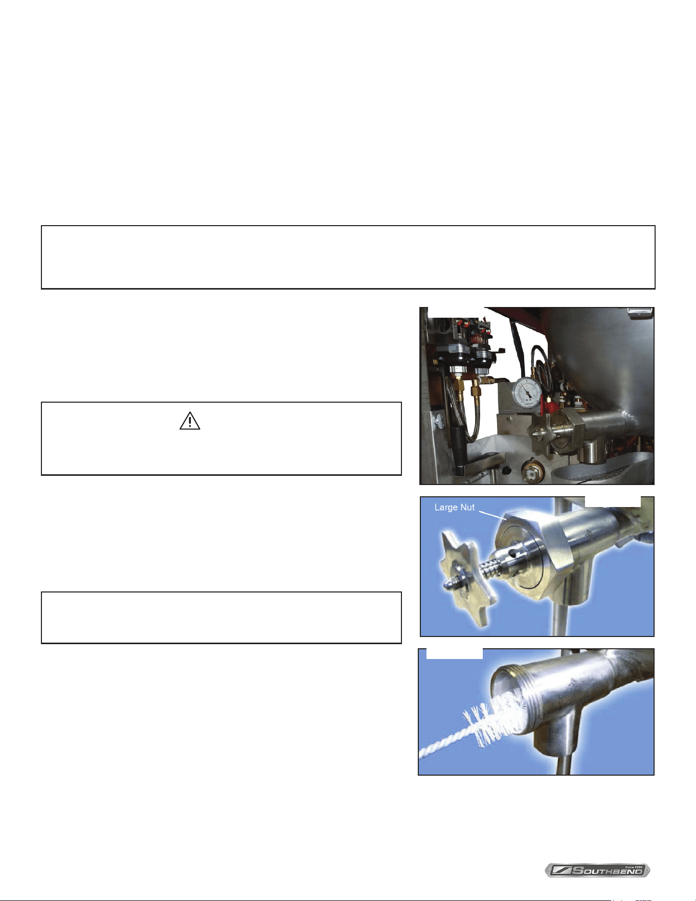
6. Remove strainer from inside kettle. Wash and rinse thoroughly.
7. Disassemble draw-o valve by rst turning valve handle
counterclockwise. Then, turn hex nut counterclockwise until valve
handle and stem are free.
8. Wash inside of draw-o valve with a nylon brush.
9. Rinse kettle valve interior and reassemble valve.
Maintenance
Daily Kettle Cleaning
The most important preventive maintenance operation on the steam jacketed kettle is the daily cleaning procedure after each use.
All kettle cleaning procedures should be faithfully completed by the end of each day’s operation. In addition, cabinet
doors, top, xtues, kettle lid, etc., should be washed and rinsed to remove all food spills.
1. Fill kettle with water and mild detergent immediately after removing food from kettle.
2. Scrub kettle interior with a nylon brush.
WARNING
DO NOT HOSE DOWN UNIT AS IT MAY CONTAIN
ELECTRICAL COMPONENTS.
NOTICE
NEVER SCRAPE KETTLE INTERIOR WITH METAL TOOLS, STEEL SCOURING PADS OR ABRASIVE CLEANERS.
Scratches will result, which will ruin the kettles general appearance and make it harder to clean and maintain in a sanitary condition.
NOTICE
Leave draw-o valve open when kettle is not in use.your gasket.
Maintenance
3. Loosen food which is stuck to kettle by allowing it to soak. Also, a
small amount of steam may help.
4. Position swing drain under draw-o valve. Open draw-o valve to
drain soapy water.
5. Wipe down exterior, rinse and dry. Avoid getting water into electrical
controls.
Figure 4
Figure 5
Figure 6
INSTALLATION & OPERATION MANUAL 14-00330-SB REV 0 (07/21)
PAGE
13
OF 16
Modular Base Electric Tilting Kettles Maintenance
Cleaning the Boiler
Replacement parts needed to complete this procedure:
Part Number Description Qtuantity
91 - 8756 Front Cover Gasket 1
08 - 0034 Southbend Steam Zinc Anode 1
81 - 8660 Heating Element Gasket 2
1. Move the heat and power switch to their o positions. This will allow the boiler to empty.
WARNING
DISCONNECT THE MAIN POWER SUPPLY.
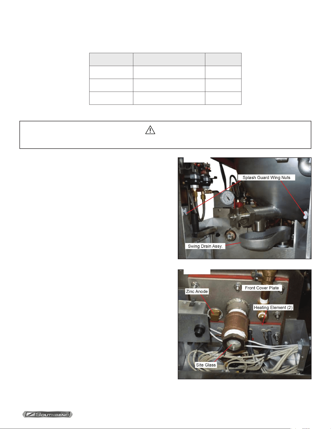
2. Remove the swing drain assembly shown in “Figure 7” and
move it safely out of the way.
3. Remove the splash guard as shown by removing the
(2) wing nuts and move it out of the way.
4. Remove the front cover to the contactor box.
5. Remove the front cover plate with elements shown in
“Figure 8” as follows:
a. Using a 1/4” socket head wrench, back o the (10) Hex-
Nuts, counterclockwise.
6. Clean rust, scale and lime deposits from the inside of the
boiler with a wire brush.
7. Remove all debris; ush out with clean water through the
opening created by removing the front cover plate with
elements and drain.
8. Remove the heating elements from the front cover plate.
Take care to not damage the heating elements, brush lightly.
9. Clean the front cover plate and element anges with a wire
brush and wash. Be sure the areas that will come in contact
with the gaskets and are clean and smooth.
To protect against further scale and corrosion remove the old
cathodic anode. Install a New Southbend Steam Zinc Anode.
Figure 7
Figure 8
INSTALLATION & OPERATION MANUAL 14-0330-SB REV 0 (07/21)
PAGE
14
OF 16
Modular Base Electric Tilting Kettles
Application Instructions for Total Concept Descaler
Southbend Steam has two basic types of boilers; one has an automatic drain valve, the other has a manual drain valve. To
determine which type you have, open cabinet doors and you will see a control box with two switches and an indicator light.
The instruction label on the control box will identify the boiler as being either automatic or manual. Those boilers
designated as being automatic must be energized in order to close the drain valve.
Total Concept is designed to be used with water between 160°F to 200°F.
Preheating is required on both automatic and manual boilers to raise the water temperature to the acceptable range
(160 °F to 200 °F)
For manual boilers, make certain drain valve is tightly closed.
Application Directions
1. Energize boiler and ll to operating level.
2. Energize heating circuit to preheat unit.
MANUAL: After unit is preheated, place the power switch in the OFF position.
DO NOT DRAIN THE UNIT.
AUTOMATIC: After unit is preheated, cycle the power switch from the ON position to the OFF position and
immediately back to the ON position.
3. Remove the shipping cap, replace it with the pouring cap. Cut the tip of the pouring cap at the rst notch to a 45° angle.
4. Install the tubing rmly over the tip of the pouring cap.
5. Cycle steam to kettle jacket. This releases steam pressure to “0” PSI in boiler, prior to step #7.
6. Disconnect terminals to forward probe. Remove the forward probe from the top or in front of the boiler shell. This
orice becomes the access port to the boiler chamber.
Maintenance
CAUTION
BOILER SHELL AND PROBE ARE HOT.
7. Feed the tubing through the access port into the boiler compartment.
NOTICE
A minimum of 4 inches must be inserted into the boiler.
8. Tilt the container, pour the contents into the unit.
9. When empty, rell the container with hot tap water and add to boiler for cleaning. Replace the probe in access port
and tighten. Reconnect terminals by re- versing removal procedure.
10. After rinsing the container, place the tubing inside the bottle, cover with the shipping cap, dispose of properly. DO NOT
RE-USE CONTAINER.
11. DO NOT ENERGIZE HEATERS - Allow 2 hours for cleaning.
12. After time has elapsed, drain the boiler.
13. Rell the boiler and drain. Repeat this step twice.
14. Bring the boiler to temperature and cycle steam to the kettle to purge cleaner/descaler from the steam supply lines.
Repeat this step twice.
15. Unit is now ready for use.

INSTALLATION & OPERATION MANUAL 14-00330-SB REV 0 (07/21)
PAGE
15
OF 16
Modular Base Electric Tilting Kettles
Notes
INSTALLATION & OPERATION MANUAL 14-0330-SB REV 0 (07/21)
PAGE
16
OF 16
Modular Base Electric Tilting Kettles
MT-25EO-SB & MT-40EO-SB
Modular Base
Electric Tilting Kettles
A product with the Southbend Steam name incorporates the best in durability and low maintenance. We all recognize,
however, that replacement parts and occasional professional service may be necessary to extend the useful life of this
appliance. When service is needed, contact a Southbend Steam Authorized Service Agency, or your dealer. To avoid
confusion, always refer to the model number, serial number, and type of your appliance.
SOUTHBEND STEAM
A Middleby Company
1100 Old Honeycutt Road Fuquay-Varina, North Carolina 27526 USA
www.southbendnc.com

