1
Note to Consumer
Leave this Owner’s Manual in a convenient
place for future reference.
Customer Service Helpline:
For parts ordering, call:
1-800-530-9133
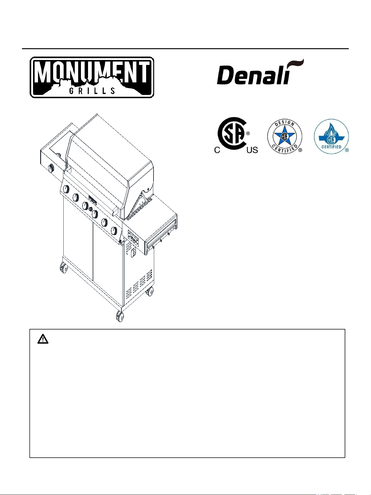
MFG No.: D605
Please make sure the cylinder valve
connection device shall properly and safely
mate with the connection device attached to
the inlet of the pressure regulator.
WARNING:
Read this Owner’s manual carefully and be
sure your gas grill is properly assembled,
installed and maintained. Failure to follow
these instructions could result in serious injury
and/or property damage. This gas grill is
intended for outdoor use only and is not
intended to be installed in or on recreational
vehicles or boats.
Note to Installer
Leave this Owner’s Manual with the customer
after delivery and/or installation.
• Parts
• Assembly
• Safety Rules
• Use and Care
• Troubleshooting
ASSEMBLY & OPERATING INSTRUCTIONS
C045257-A3
Liquid Propane Gas Grill
605
2
WARNING
Your grill will get very hot. Never lean over the
cooking area while using your grill. Do not touch
cooking surfaces, grill housing, lid or any other
grill parts while the grill is in operation, or until
the gas grill has cooled down after use.
Failure to comply with these instructions may
result in serious bodily injury.
One-Year Full Warranty on Grill
If this grill fails due to defective material or workmanship
within one year from the date of purchase,contact us to
arrange for a free repair (or replacement if repair proves
impossible).
8-Year Limited Warranty on Stainless Steel Burners
For eight years from the date of purchase, any stainless
steel burner that rusts through will be replaced free of
charge. After the first year from the date of purchase, you
pay for labor if you wish to have it installed.
All warranty coverage excludes ignitor batteries and grill
part paint loss, discoloration or rusting, which are either
expendable parts that can wear out from normal use
within the warranty period, or are conditions that can be
the result or normal use, accident or improper
maintenance.
All warranty coverage is void if this grill is ever used for
commercial or rental purposes.
All warranty coverage applies only if this grill is used in
the North America.
This warranty gives you specific legal rights, and you
may have other right which vary from state to state.
The warranty is only valid for original purchasers with
proof of purchase from authorized retailers. Any product
bought second hand or through an unauthorized retailer,
will not be covered by warranty. It is the duty of the
purchaser to verify that a retailer is authorized. A
purchase on Amazon or other marketplace internet
retailer from any entity other than Monument Grills is not
an original purchase and will not qualify for a warranty
WARNING
Combustion by products produced when using
this product contain chemicals known to the
State of California to cause cancer, birth defects,
or other reproductive harm.
WARNING
Failure to comply with these instructions could
result in a fire or explosion that could cause
serious bodily injury, death, or property damage.
WARNING
1. Do not store or use gasoline or
other flammable liquids or
vapors in the vicinity of this or
any other appliance.
2. An LP cylinder not connected for
use shall not be stored in the
vicinity of this or any other
appliance.
DANGER
If you smell gas:
1. Shut off gas to the appliance.
2. Extinguish any open flame.
3. Open lid.
4. If odor continues, keep away
from the appliance and
immediately call your gas
supplier or your fire department.
Grill Installation Codes
The installation must conform with local codes or, in the
absence of local codes, with either the national fuel gas
code, ANSI Z 223.1/NFPA S4, Natural gas and propane
installation code, CSA B149.1, or propane storage and
handling code, B149.2, or the standard for Recreational
vehicles, ANSI A 119.2, and CSA Z240 RV series
recreational vehicle code, as applicable.
LP gas grill models are designed for use with a standard
20 lb. Liquid Propane Gas tank, not included with grill.
Never connect your gas grill to an LP gas tank that
exceeds this capacity.
Grill Warranty
Safety PrecautionsTable of Contents
Warranty-------------------------------------------------2
Safety Precautions---------------------------------3~4
Hardware List-------------------------------------------5
Assembly Diagram -----------------------------------6
Assembly List-------------------------------------------7
Assembly Instructions ----------------------------8~20
Lighting Instructions ----------------------------21~22
Digitemp Display&APP Instructions --------23~25
Cleaning and Maintenance -------------------26~27
Troubleshooting---------------------------------------27
Part Diagram-------------------------------------------28
Part List--------------------------------------------------29
Cooking Instruction------------------------------------30
Cooking Chart------------------------------------------31
Natural Gas Conversion------------------------32~39
3
• Have your LP gas tank filled by a reputable
propane gas dealer and visually inspected and
re-qualified at each filling.
• Do not store a spare LP gas tank under or
• Never fill the tank beyond 80 percent full . If this
information is not followed exactly a fire causing
death or serious injury may occur.
• Always keep LP gas tanks in an upright position.
• Do not store (or) or use gasoline or other
flammable vapors and liquids in the vicinity of this
gas grill.
• Do not subject the LP gas tank to excessive heat.
• Never store an LP gas tank indoors. If you store
your gas grill in the garage or other indoor
location, always disconnect the LP gas tank first
and store it safely outside.
• Place dust cap on cylinder valve outlet whenever
the cylinder is not in use. Only install the type of
dust cap on the cylinder valve outlet that is
provided with the cylinder valve. Other types of
caps or plugs may result in leakage of propane.
• LP gas tanks must be stored outdoors in a well-
ventilated area and out of reach of children.
Disconnected LP gas tanks must not be stored in
a building, garage or any other enclosed area.
• When your gas grill is not in use the gas must be
turned off at the LP gas tank.
• The pressure regulator and hose assembly must
be inspected before each use of the grill. If there
is excessive abrasion or wear or if the hose is cut,
it must be replaced prior to the grill being used
again.
• Keep the gas regulator hose away from hot grill
surfaces and dripping grease. Avoid unnecessary
twisting of hose. Visually inspect the hose prior to
each use for cuts, cracks, excessive wear or
other damage.
• Never light your gas grill with the lid closed or
before checking to ensure the burner tubes are
fully seated over the gas valve orifices.
• Never allow children to operate your grill.
A tank of approximately 12 inches in diameter by 18-
1/2 inches high is the maximum size LP gas tank to
use. You must use an OPD gas tank which offers
an Overfill Prevention Device.
This safety feature prevents the tank from being
overfilled which can cause malfunction of the LP gas
tank, regulator and/or grill.
The LP gas tank must be constructed and marked in
accordance with specifications of the U.S. Dept. of
Transportation (DOT). In Canada, the LP gas tank
must meet the National Standard of Canada ,Can
CSA –B339 , Cylinders , spheres and Tubes for
Transportation of Dangerous Goods and
Commission .
1. The LP gas tank must have a shutoff valve,
terminating in an LP gas supply tank valve outlet,
that is compatible with a Type 1 tank connection
device. The LP gas tank must also have a safety
relief device that has a direct connection with the
vapor space of the tank.
2. Always keep LP gas tanks in an upright position.
The tank supply system must be arranged for vapor
withdraw.
3. The LP gas tank used must have a collar to
protect the tank valve.
Proper Placement and Clearance of Grill
Never use your gas grill in a garage, porch, shed,
breezeway or any other enclosed area. Your gas
grill is to be used outdoors only, at least 24 inches
from the back and side of any combustible surface.
Your gas grill should not be used under overhead
combustible construction . Do not obstruct the flow
of ventilation air around the gas grill housing.
• Do not install this outdoor gas grill in or on
recreational vehicles or boats
• Keep outdoor gas grill area clear and free from
combustible materials, gasoline and other
flammable vapors and liquids
• Do not obstruct the flow of combustion and
ventilation air. Check for this each time prior to using
grill.
• Never connect an unregulated LP gas tank to your
gas grill. The gas regulator assembly supplied with
your gas grill is adjusted to have an outlet pressure
of 11” water column (W.C.) for connection to an LP
gas tank.
• Only use the regulator and the hose assembly
supplied with your gas grill. Replacement regulators
and hose assemblies must be those specified in this
manual.
Safety Precautions
4
WARNING
A strong gas smell, or the hissing sound of gas
indicates a serious problem with your gas grill or
the LP gas tank. Failure to immediately follow the
steps listed below could result in a fire or
explosion that could cause serious bodily injury,
death, or property damage.
• Shut off gas supply to the gas grill.
• Turn the control knobs to OFF position.
• Put out any flame with a proper fire
extinguisher.
• Open Grill Lid.
• Get away from the LP gas tank.
• Do not try to fix the problem yourself.
• If odor continues or you have a fire you can not
extinguish, call your fire department. Do not call
near the LP gas tank because your telephone is
a form of electrical device and could create a
spark resulting in fire and/or explosion.
CAUTION: Spiders and small insects occasionally
spin webs or make nests in the grill burner tubes
during transit and warehousing. These webs can lead
to gas flow obstruction which could result in a fire in
and around burner tubes. This type of fire is known as
“FLASH-BACK” and can cause serious damage to
your grill and create an unsafe operating condition for
the user.
Although an obstructed burner tube is not the only
cause of “FLASH-BACK”, it is the most common
cause.
To reduce the chance of “FLASH-BACK”, you must
clean the burner tubes before assembling your grill,
and at least once a month in late summer or early fall
when spiders are most active. Also perform this burner
tube cleaning procedure if your grill has not been used
for an extended period of time.
See Cleaning Burner Tubes and Burner Ports on
page # 26
NOTE: The normal flow of gas through the regulator
and hose assembly can create a humming noise. A
low volume of noise is perfectly normal and will not
interfere with operation of the grill. If humming noise
is loud and excessive you may need to purge air
from the gas line or reset the regulator excess gas
flow device. This purging procedure should be done
every time a new LP gas tank is connected to your
grill. For help with this procedure refer to page 22,
Item 4 of “If Grill Still Fails To Light”.
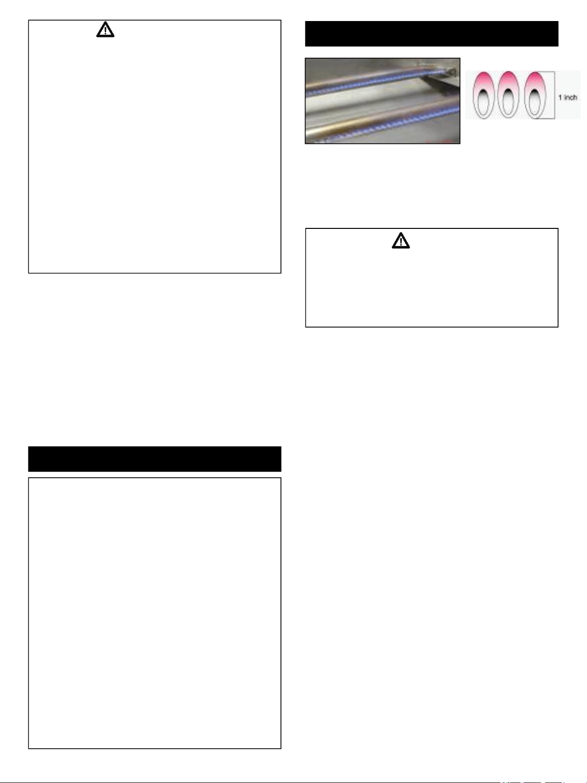
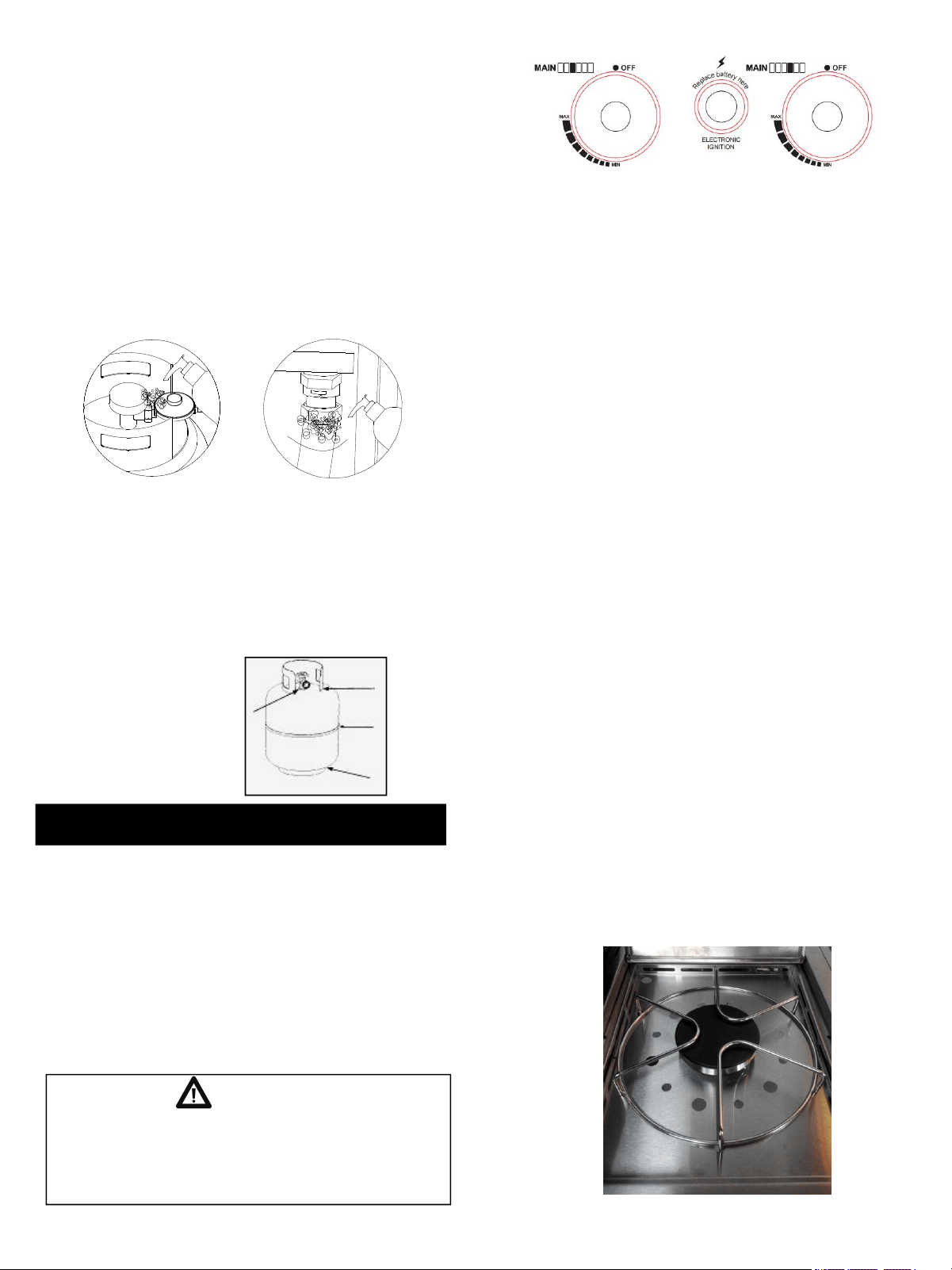
Visually check the burner flames prior to each use.
The flames should look like picture, if they do not,
refer to the cleaning Burner Tubes and Burner Ports,
see page 26 of this manual.
CAUTION: Beware of Flash-Back
Burner Flame Check
WARNING
Pls ensure cleaning the flame tamer/cooking
grid/grease pan/tray after each use. Failure to
comply this could result in a fire or explosion that
could cause serious bodily injury, death, or
property damage.
5
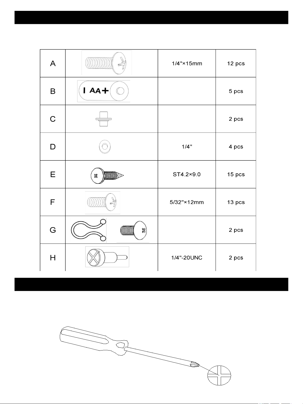
The following table illustrates a breakdown of the hardware pack. It highlights what components are used in
the various stages of assembly.
Contents for Hardware Pack
Tools required for assembly
Philips Head Screwdriver (not included).
Note: The left and right sides of the grill are on your left and right as you face the front of the grill.
Philips Head Screwdriver
6
A
A
A
A
A
A
A
A
A
A
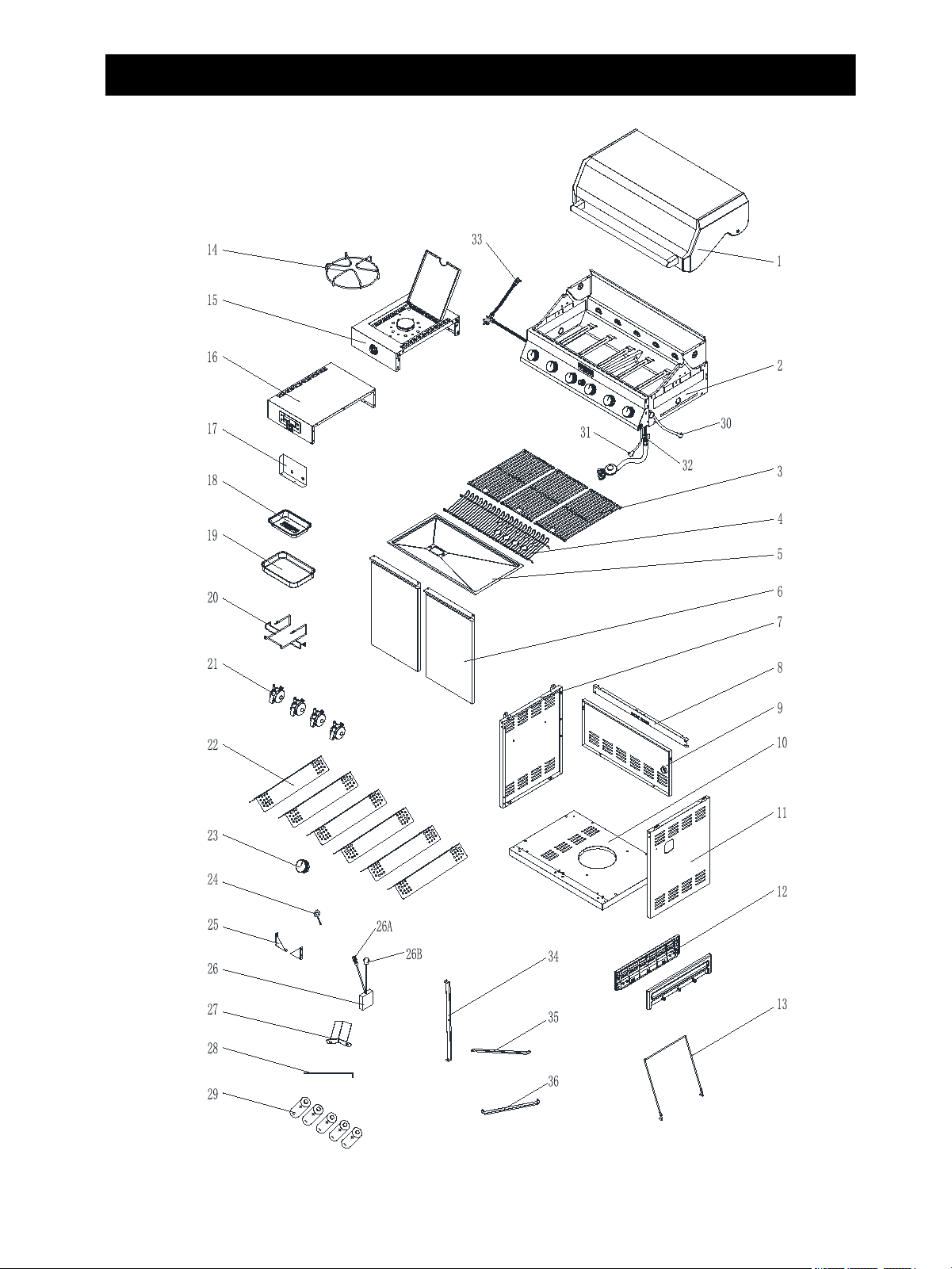
Model Denali 605 Assembly Diagram
7
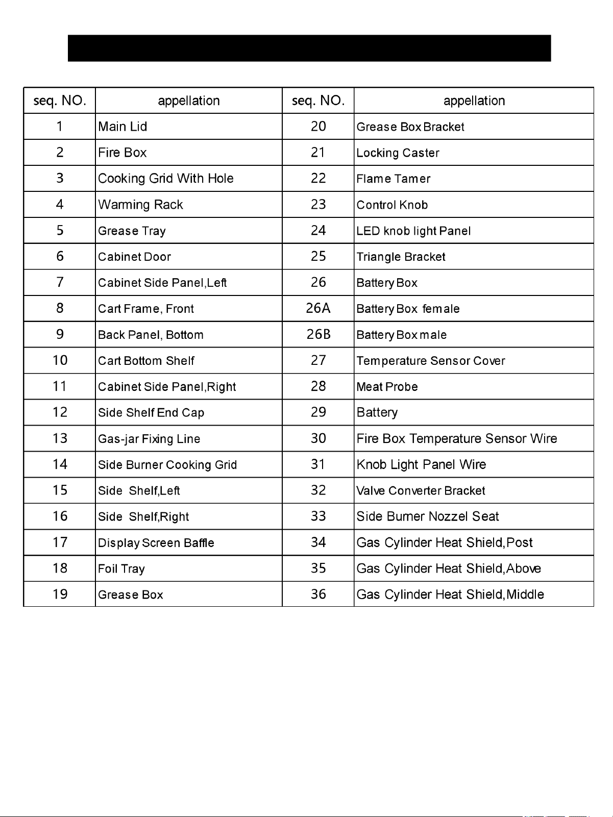
Model Denali 605 Assembly List
8
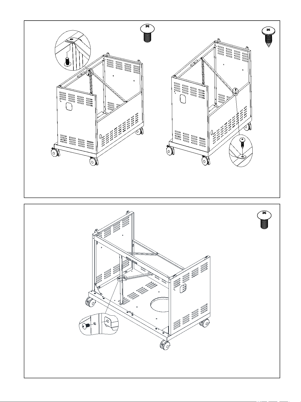
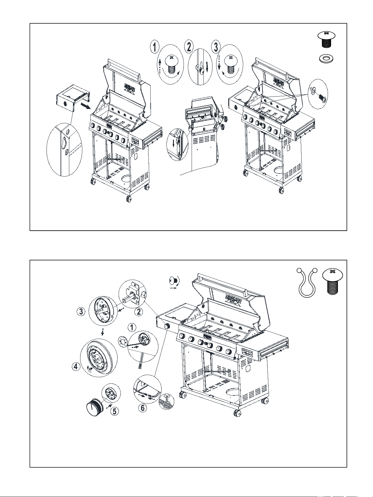
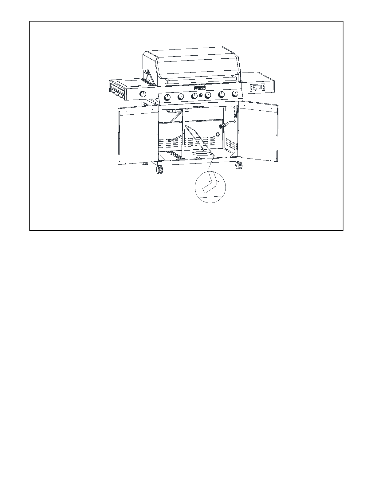
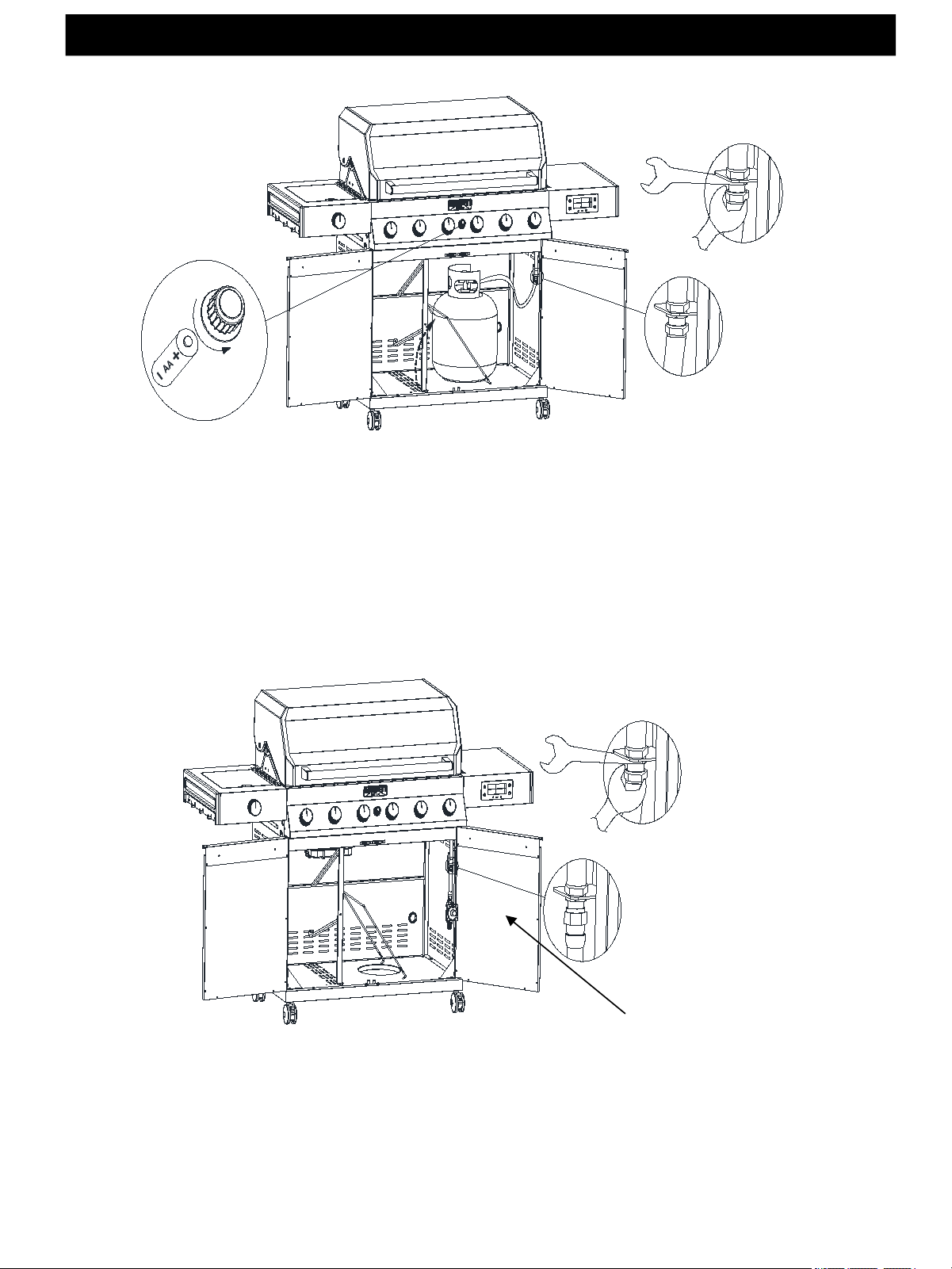
Please insert Locking Caster(No.21) into the bottom plate(No.10).
Figure 2
Assembly Instructions
Figure 1
Half screw out the screws in the bottom plate, then put Cabinet
Side Panel,Left(No.7) and Cabinet Side Panel,Right(No.11) onto
the relevant screw holes and screw tightly.
9
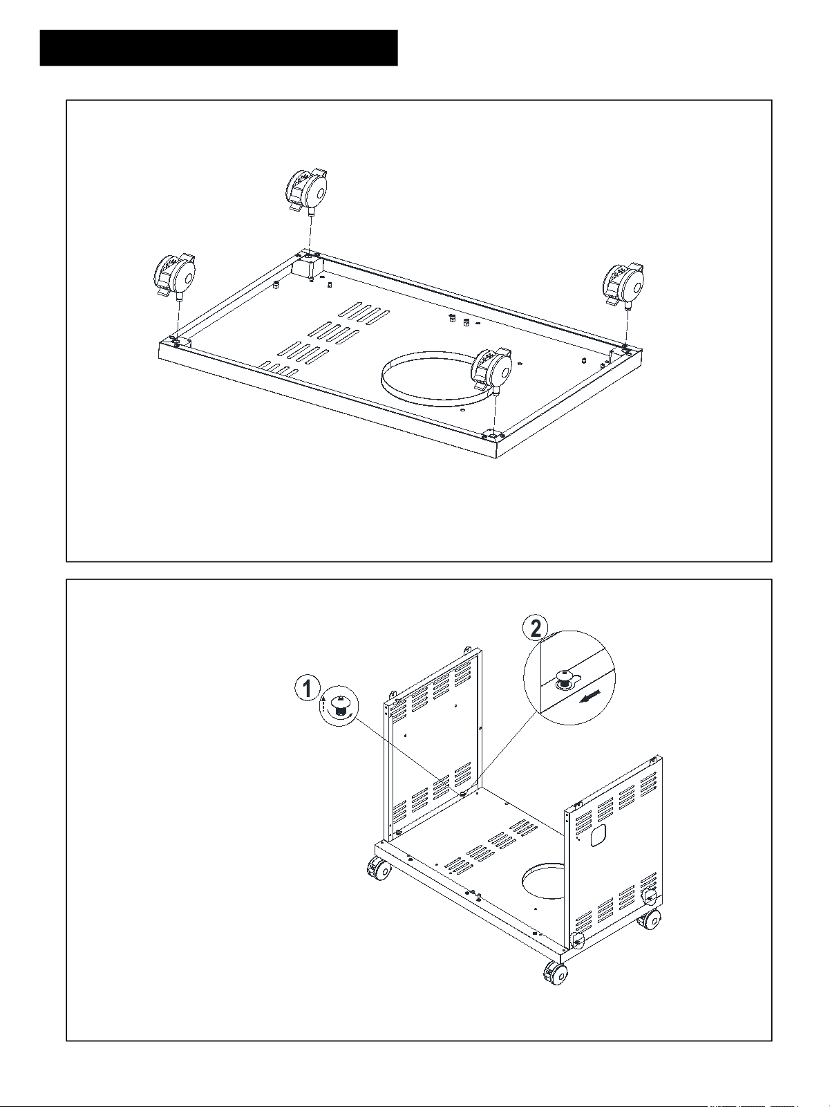
Figure 4
Figure 3
4 × A
Install Back Panel, Bottom(No.9) onto
the relevant place with four A screws.
Half screw out the screws in the bottom and
side plates, then put Triangle Bracket(No.25)
onto the relevant screw holes and screw tightly.
10
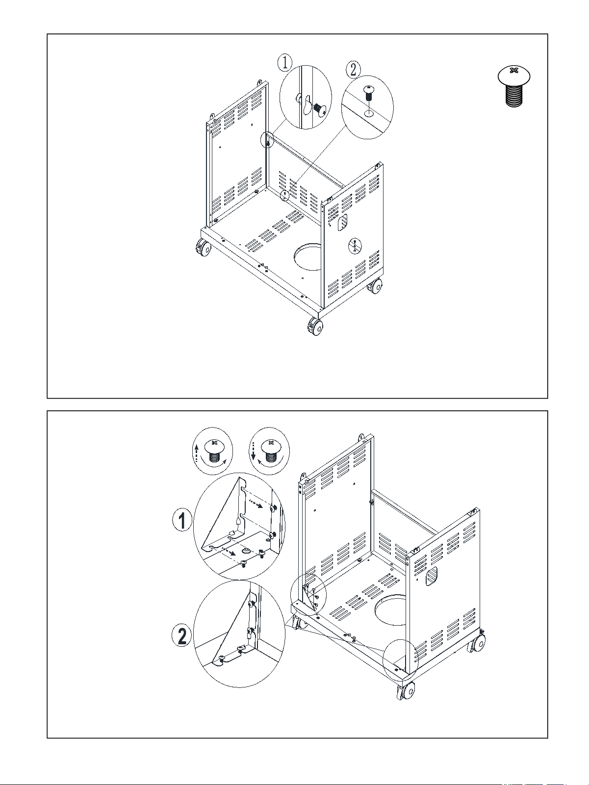
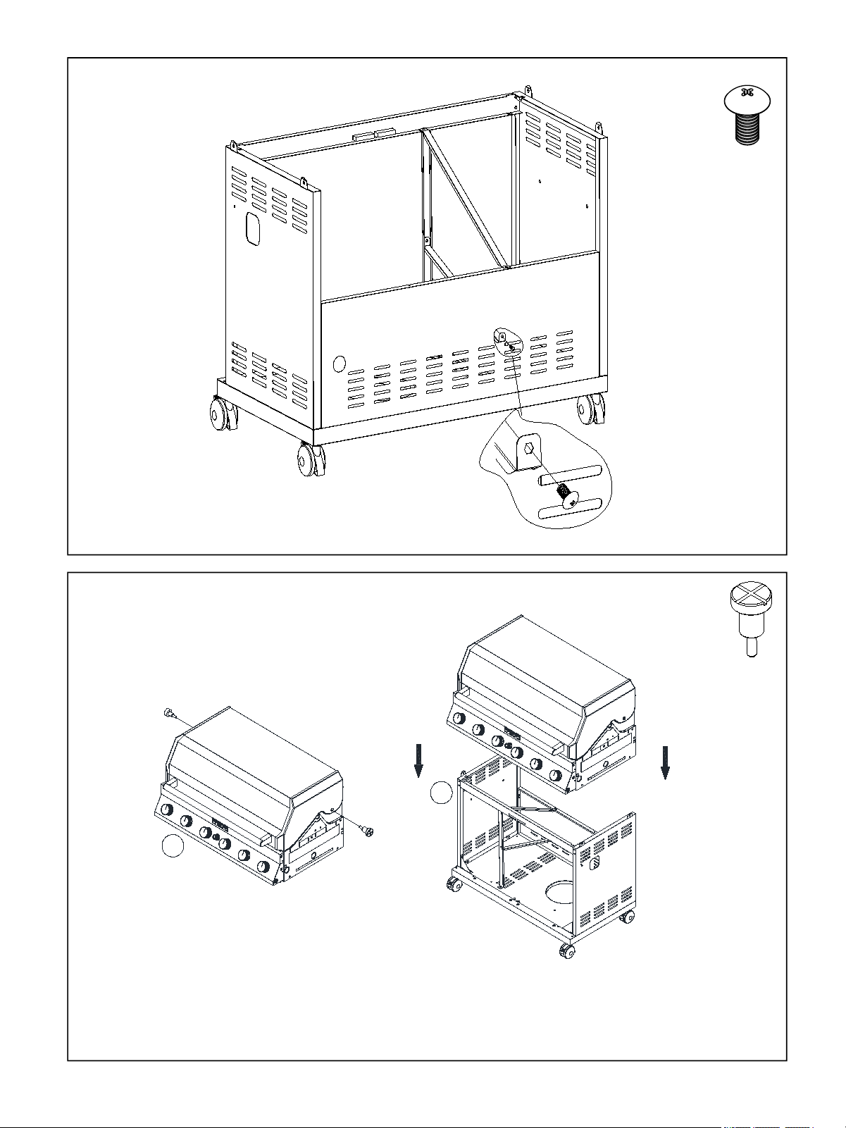
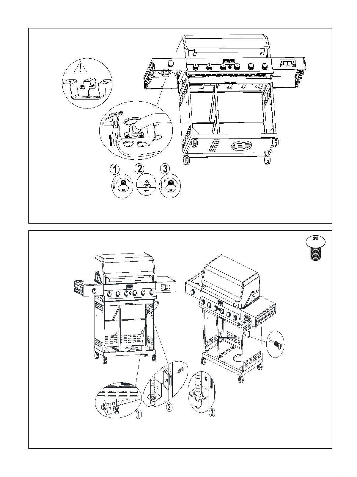
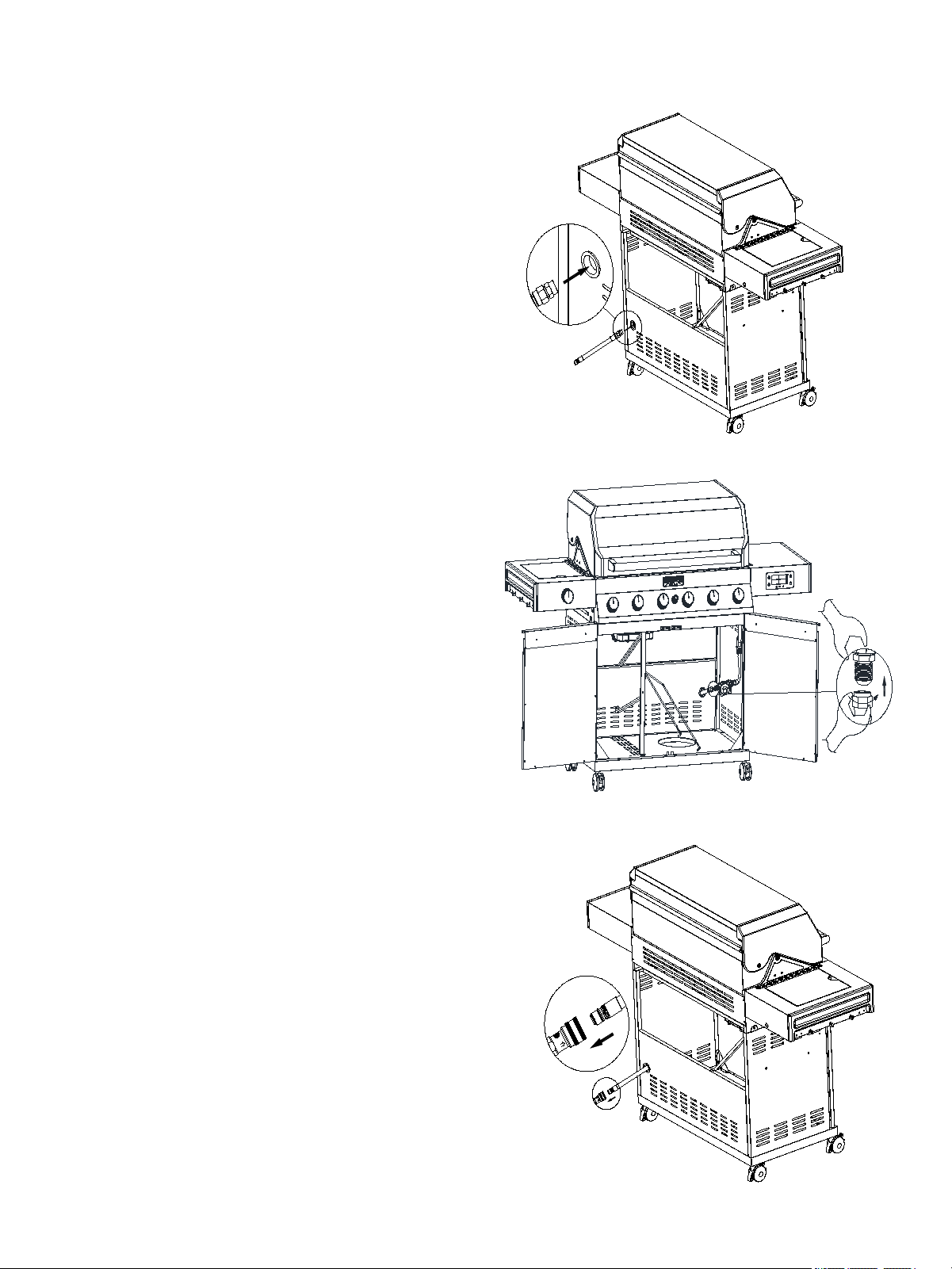
Figure 5
Figure 6
4 × F
1 × F
Install Cart Frame, Front(No.8) onto the
relevant place with four F screws.
Attention: magnet downward.
Install Gas Cylinder Heat Shield,Post(No.34) onto
Cart Bottom Shelf(No.10) with F screws.
11
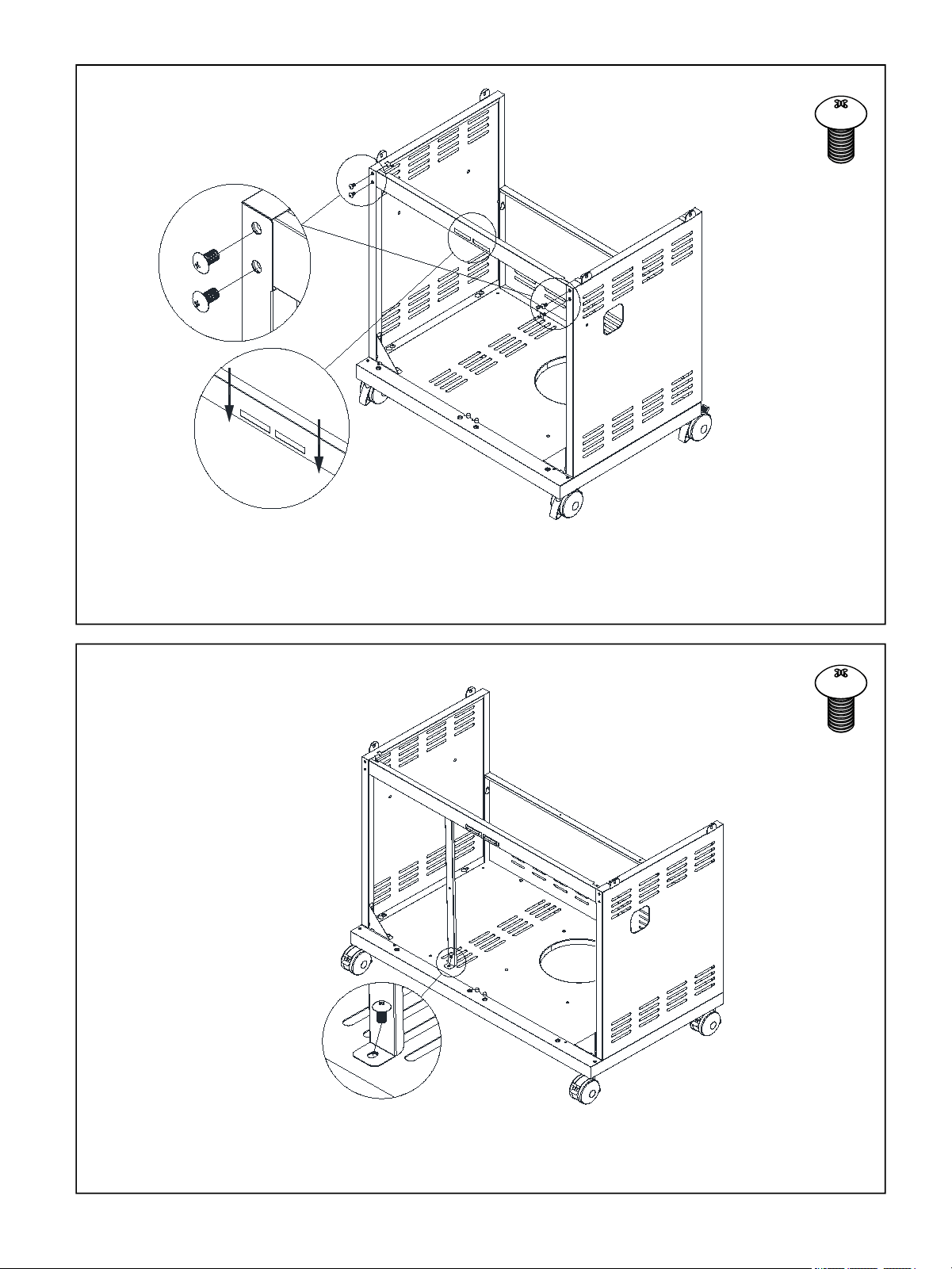
Figure 8
1 × F
1 ×E
Figure 7
1 × F
1.Install Gas Cylinder Heat Shield,Post(No.34) ,Gas Cylinder Heat
Shield,Above(No.35) onto Cart Frame, Front(No.8) with F screws.
2.Install Gas Cylinder Heat Shield,Above(No. 35) onto Back Panel, Bottom(No.9).
Install Gas Cylinder Heat Shield,Above(No. 35) onto Part
Gas Cylinder Heat Shield,Post(No.34) with F screws.
12
1
2
Figure 9
Figure 10
1 × F
2 × H
1: Install main lid to firebox with Fire Box(No.2).
2: Put the assembly of firebox & main lid onto the grill cart.
Install Gas Cylinder Heat Shield,Middle(No.36) onto
Back Panel, Bottom(No.9) with F screws.
13
Figure 11
4 × A
Figure 12
Screw the grill body and the cart tightly with four A screws.
12 × E
Install Side Shelf End Cap(No.12) onto the Side Burner Cooking Grid(No.16)
& Side Shelf,Left(No.15) and tighten it with twelve E screws.
2
1
2
1
14
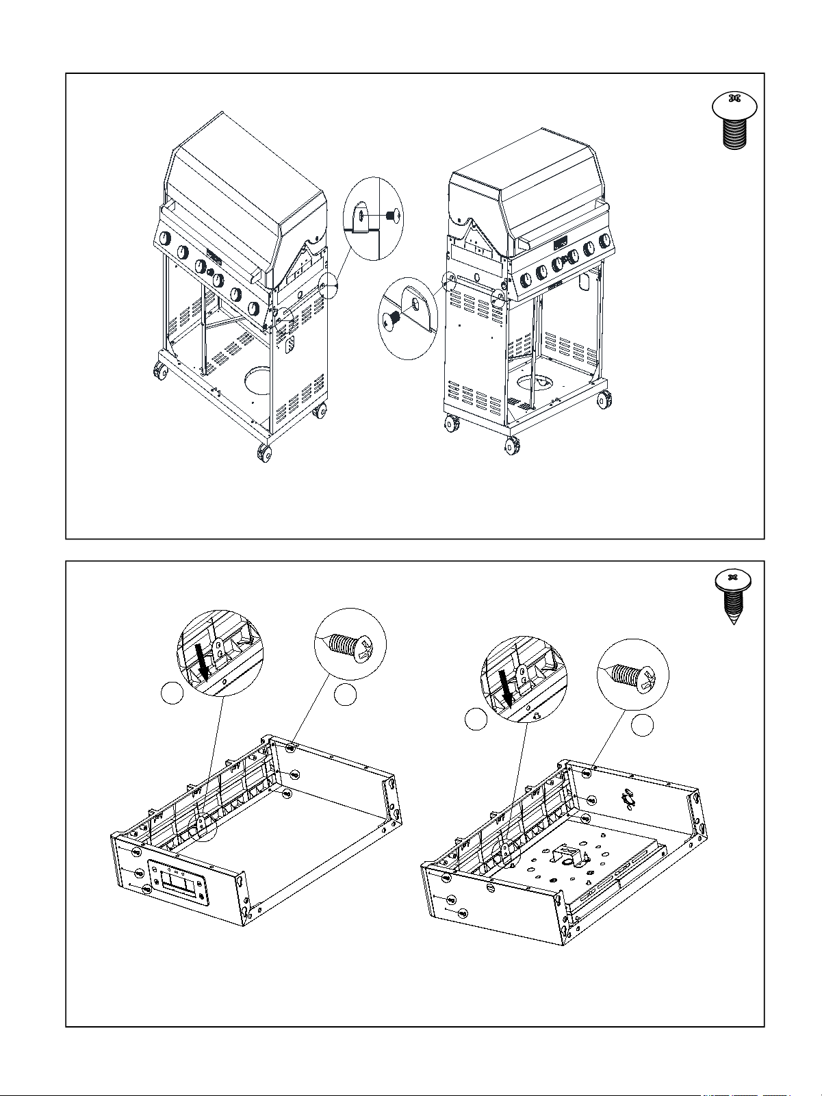
Figure 13
2 × A
2 × D
Figure 14
1.Half screw out the three big screws on the grill body, then put Side Shelf,Right(No.16)
onto the relevant screw holes and screw tightly.
2.Screw Side Shelf,Right(No.16) tightly with A screw and D spacer inside the grill body.
2 × E
3
21
1.Install Display Screen Baffle(No.17) onto Side Shelf,Right(No.16) and tighten it
with two E screws.
2.Connect Battery Box female(No.26A) with I,Battery Box male(No.26B) with Knob
Light Panel Wire(No.31) and Fire Box Temperature Sensor Wire(No.30) with II.
15
2 × A
2 × D
Figure 16
Figure 15
1.Half screw out the three big screws outside the grill body, then put Side
Shelf,Left(No.15) onto the relevant screw holes and screw tightly.
2.Screw Side Shelf,Left(No.15) tightly with A screw and D spacer inside the grill body.
1. Insert Side Shelf,Left(No.15) , Control Knob(No.23)
and LED knob light Panel(No.24) as the figure shows.
2. Insert the wire as the figure shows.
2 × G
16
Figure 17
Half screw out the screw in Side Burner Nozzel Seat(No.33), then
put it into the hole of Side Shelf,Left(No.15) and screw tightly.
Figure 18
1 × F
Fixed Valve Converter Bracket(No.32) onto the right plate with one F screw.
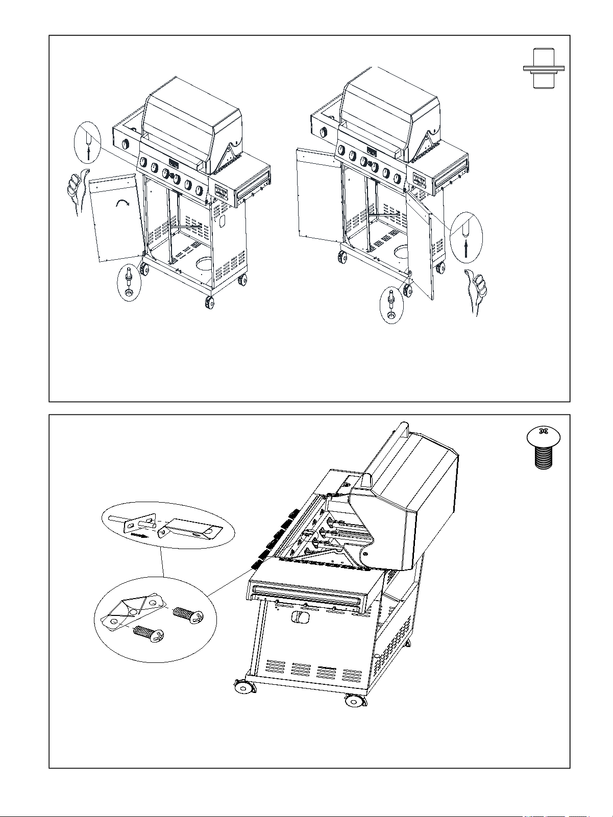
17
1.Put the C part into the relevant hole in the bottom plate.
2.Put Cabinet Door(No.6)into the C part.
3.Then put the door into by pressing the flexible axis upward.
Figure 19
C
C
Figure 20
2 × F
Install Temperature Sensor Cover(No.27) onto Fire Box(No.2) with two F screws.
2 × C
18
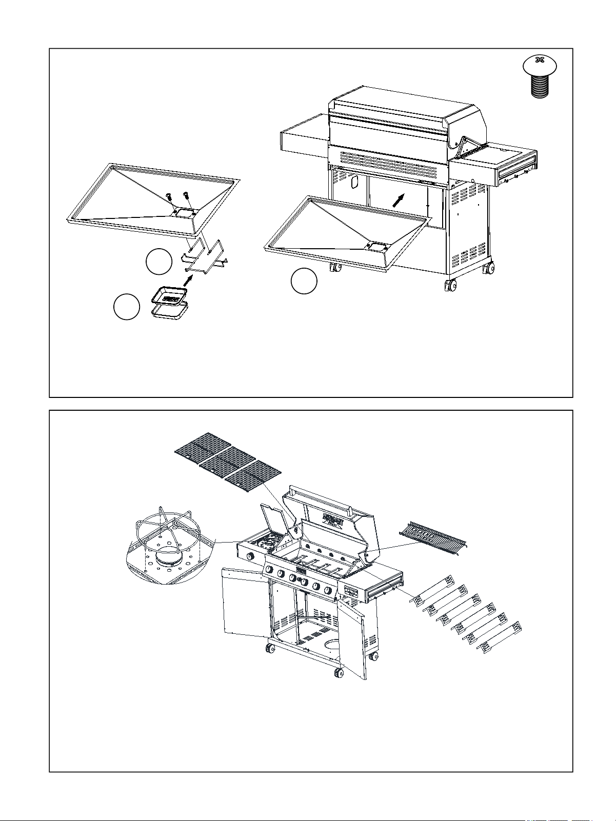
Figure 21
Figure 22
2
3
2 × F
1.Install Grease Box Bracket(No.20) onto Grease Tray(No.5) with two F screws.
2.Put Foil Tray(No.18) and Grease Box(No.19) into Grease Box Bracket(No.20).
3.Put the grease tray into the grill body.
1
Put Cooking Grid With Hole(No.3), Warming Rack(No.4) , Side Burner
Cooking Grid(No.14) and Flame Tamer(No.22) into the relevant place.
19
Figure 23
Install Gas-jar Fixing Line(No. 13) onto the bottom plate.
20
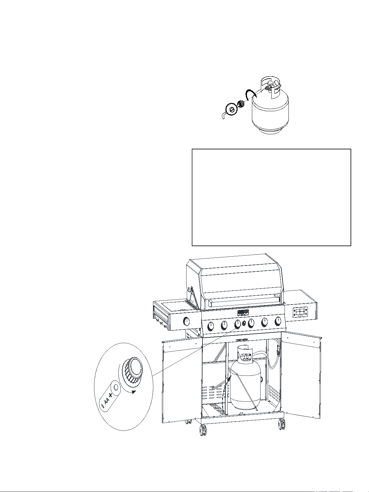
Connecting LP Gas Tank to LP Grill
1. Place foot ring of 20 lb tank into the hole in bottom
panel. Make sure the tank valve is in OFF
position.(Fig.25).
2. Check the tank valve to ensure it has proper
external mating threads to fit the hose and regulator
assembly provided.
3. Make sure all burner valves are in OFF position.
4. Inspect the valve connection port and regulator
assembly. Look for damage or debris. Remove any
debris. Inspect hose for damage. Never use
damaged or plugged equipment.
5. When connecting regulator and hose assembly to
tank valve hand tighten quick coupling nut clockwise
to a full stop (Fig.24) Do not use a wrench to tighten
because it could damage the quick coupling nut and
result in a hazardous condition.
6. Open tank valve fully (counterclockwise). Use a
soapy water solution to check all connections for
leaks before attempting to light your grill. If a leak is
found, turn tank valve off and do not use your grill
until the leak is repaired.
CAUTION: When the appliance is not in use, gas
must be turned off at the supply tank.
Figure 25
Regulator Connection
Figure 24
Congratulations
Your gas grill is now ready for use. Before the
first use and at the beginning of each season
(and whenever the LP gas tank has been
changed):
1. Read all safety, lighting and operating
instructions.
2. Check gas valve orifices, burner tubes and
burner ports for any obstructions.
3. Perform gas leak check according to
instructions found on next page of the manual.
21
LIGHTING INSTRUCTIONS FOR SIDE BURNER
1. Open side burner lid fully.
2. Push and turn side burner knob to IGNITE/HI
position. At the same time, press and hold
electronic ignition button for 3 to 5 seconds to
light burner.
3. If the side burner does not light after 5 seconds,
turn knob to OFF. Turn gas OFF at LP tank and
wait 5 minutes for gas to clear. Then turn gas
ON at tank and repeat step 2.
4. If burner still does not light, see Match Lighting
section and If Grill Still Fails to Light section on
following page.
Grill Lighting Instructions for Main Burners
1. Do not smoke while lighting grill or checking gas
supply connections.
2. Be sure that LP gas tank is sufficiently full.
3. Be sure all gas connections are securely tightened.
4. Turn on gas supply
5. Open the grill main lid and side burner lid.
6. Push and turn any main burner knob to MAX.
7. If the burner does not light after 5 seconds, turn
knob to OFF. Turn gas OFF at LP tank and wait 5
minutes for gas to clear. Then turn gas ON at tank
and repeat step 6.
8. If burner still does not light, see Match Lighting
section and If Grill Still Fails to Light section on
following page.
1. Make a 50/50 (soap/water) mild soap solution.
2. Turn the control knobs to full OFF position. then
turn gas ON at supply tank.
3. Apply the soap solution with a clean brush to all
gas connections. See below. If growing bubbles
appear in the solution the connections are not
properly sealed. Check each fitting and tighten or
repair as necessary.
4. If you have a gas connection leak you cannot
repair, turn gas OFF at supply tank, disconnect
fuel line from your grill or contact your gas supplier
for repair assistance.
5. Also apply soapy solution to the tank seams. See
below. If growing bubbles appear, shut tank OFF
and do not use or move it! Contact an LP gas
supplier or your fire department for assistance.
WARNING
Failure to open grill lid during the lighting
procedure could result in a fire or explosion
that could cause serious bodily injury, death,
or property damage.
USING THE SIDE BURNER
Inspect the gas supply hose prior to turning the
gas “ON”. If there is evidence of cuts, wear or
abrasion, it must be replaced prior to use. Do not
use the side burner if the odor of gas is present.
WARNING: Always keep your face and body as
far away from the burner as possible when
lighting.
Gas Connection Leak Check
Gas Tank Leak Check
Checking for LP gas leaks
Never test for leaks with a flame. Prior to first use, at
the beginning of each season, or every time your LP
gas tank is changed, you must check for gas leaks.
Grill Lighting Instruction
22
WARNING
Never lean over the grill cooking area while
lighting your gas grill. Keep your face and body
a safe distance (at least 18 inches) from the
cooking grid surface when lighting your grill by
match.
If Grill Still Fails To Light
1. Check gas supply and connections for leaks. Check
that all wire connections are secure.
2. Repeat basic lighting procedure. If your grill still fails
to operate, turn the gas off at source, turn the control
knobs to OFF, then check the following:
• Misalignment of burner tubes over orifices.
Correction: Reposition burner tubes over orifices.
•Obstruction in gas line.
Correction: Remove fuel line from grill. Do not smoke!
Open gas supply for 1 second to clear any obstruction
from fuel line. Close off gas supply at source and
reconnect fuel line to grill.
• Plugged orifice.
Correction: Remove burners from grill, carefully lift
each burner up and away from gas valve orifice.
Remove the orifice from gas valve and gently clear any
obstruction with a fine wire. Then reinstall all orifices,
burners, and cooking components.
3. If an obstruction is suspected in gas valves, please
contact us.
4. If the grill still does not light you may need to purge
air from the gas line or reset the regulator excess gas
flow device. Note: This procedure should be done every
time a new LP gas tank is connected to your grill.
To purge air from your gas line and/or reset the
regulator excess gas flow device:
• Turn the control knob to OFF position.
• Turn off the gas at the tank valve.
• Disconnect regulator from LP gas tank.
• Let unit stand for 5 minutes.
• Reconnect regulator to the LP gas tank.
• Turn the tank valve on slowly until ¼ to ½ open.
• Open the grill lid.
• Set control knobs to OFF. Push and turn any control
knob to HIGH.
• Turn control knobs to HIGH until all the burners are lit
• You may start to use the grill.
WARNING
Should a “FLASH-BACK” fire occur in/or around
the burner tubes, follow the instructions below.
Failure to comply with these instructions could
result in a fire or explosion that could cause
serious bodily injury, death, or property damage.
• Shut off gas supply to the gas grill.
• Turn the control knobs to OFF position.
• Put out any flame with a proper fire extinguisher.
• Open grill lid.
• Once the grill has cooled down, clean the burner
tubes and burners according to the cleaning
instructions found on page 26.
Manually Lighting Your Grill by Match
1. Take the manual lighting stick.
2. Insert a match into the lighting stick.
3. Follow steps 1 through 5 of the Basic Lighting
Procedure.
4. Light the match and extend the lighting stick to
cooking grid surface.
5. Turn the desired control knob to the HI/position
setting to release gas. The burner should light
immediately.
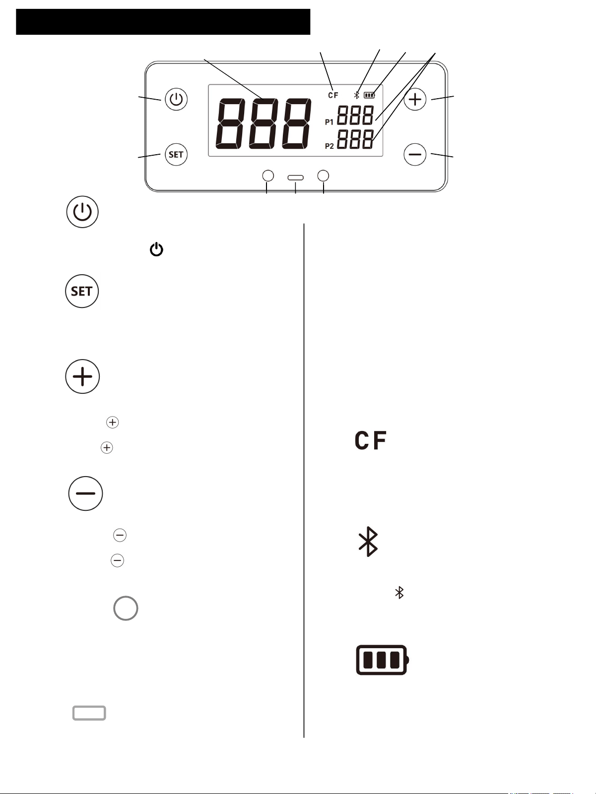
23
• Short press to increase the target temperature
of meat probe, each press adds 1.8°F.
• Long press to increase the target temperature
continuously.
C
Temperature Increase Button
A
E
C
F
G
D
B
①
②
③ ④ ⑤
A
Power Button
Short Press power button to turn on and turn off
the Digitemp Display.
B
Setup Button
SET
• Short press to shift meat probe 1 and 2.
• Press for 2 seconds to shift °C or°F.
SET
• Short press to decrease the target temperature
of meat probe, each press substracts 1.8°F.
• Long press to decrease the target temperature
continuously.
E & F
Meat Probes Plug
Monument Digitemp can handle up to two separate
meat temperature probes (one probe included) to
gain superior control of your grill for perfect results
every time.
D
Temperature Decrease Botton
G
Type-C USB Socket
The Type-C USB Socket allows you to connect
mobile charging power bank for power supply.
Display Icons
①
This area displays real-time firebox temperature .
②
Meat Probe Temperature Display
This area displays real-time meat probe temperature
while the proble is inserted. Without probe inserted,
the display will be shown as “---”.
③
④
Celcius and Fahrenheit Dgree
Bluetooth Connection Status
Press for 2 seconds to shift°C or°F display.
SET
Bluetooth icon is flashing while not connected to the
APP, and will be stable after connect to the APP.
⑤
Battery Gauge
Battery gauge will show the battery level with the three
bars,Without any bar and the frame will flash to remind
you to replace battery.
Monument Digitemp Display Instructions
Firebox Temperature Display
24
1. Turn on the Display
2. Shift Temperature in Celsius or Fahreheit
Short press power button to turn on Digitemp Display while Display is off.
Press setup button for 2 seconds to choose the temperature mode in Celsius or Fahreheit. Once it is setup,
the temperature mode will be fixed in one mode until you setup again.
SET
3. Setup Meat Probe Temperature
Insert the meat probe into the plug, and short press setup button to set the target temperature.
• After the first press, the temperature icon for P1 will be flashing.
• After the second press, the temperature icon for P2 .
• Increase or decrease the target temperature by pressing or button: each short press adds or deducts
1.8°F, while long press to increase or decrease the target temperature continuously. The temperature
range of meat probe is 104°F-212°F.
• The thrid press will confirm all the setup.
• There will be a beep when the meat temperature is reached to the target temperature.
SET
4. Screen Saver
5. Turn off the Display
Short Press power button to turn off Digitemp Display while Display is on.
The screen will sleep after 120 seconds without any operation. The screen will be waken up by press any button.
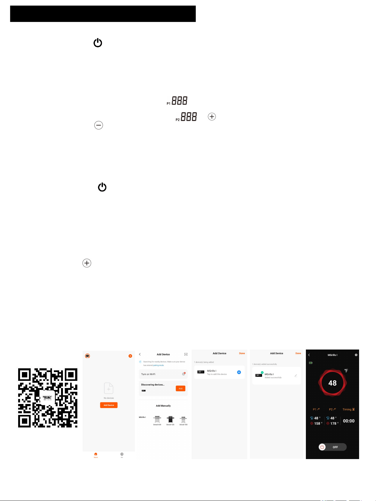
6. Bluetooth and App Connection
• Scan the QR code below and download the APP (Monument Grills) ,or search "Monument Grills" in APP store.
• After download the APP, initiate Bluetooth function of your phone, meanwhile turn on the Digitemp Display on
the grill.
• Open the APP, click orange “Add Device” button, the APP will search Monument smart Grills nearby (Step 1).
• A grill icon will be shown below “Discovering devices” after the smart grill is detected by the APP, click the orange
“Add” button to the next step(step 2).
• Click the blue icon to confirm adding the grill (step 3).
• There will be a green tick above the grill to indicate the grill is adding successfully, and click Done” on the upright
corner to go to next step. You can rename the grill in this page with the grey pen icon at the right side of the grill
(step 4).
• The real-time temperature is shown in this page, and you can adjust probe temperature or select the recipe you
would like to use, detail in next page(step 5).
*Bluetooth range: in empty flat area without any obstacle, the bluetooth range is 115 feet. and the range will be 10
feet with a wall or other similar obstacle.However,maximum communication range will vary depending on
obstacles(person, metal, wall, etc.) or electro-magnetic environment.
Step 1 Step 2 Step 3 Step 4 Step 5
Monument Digitemp Display Instructions
https://a.smart321.
com/commobunent
25
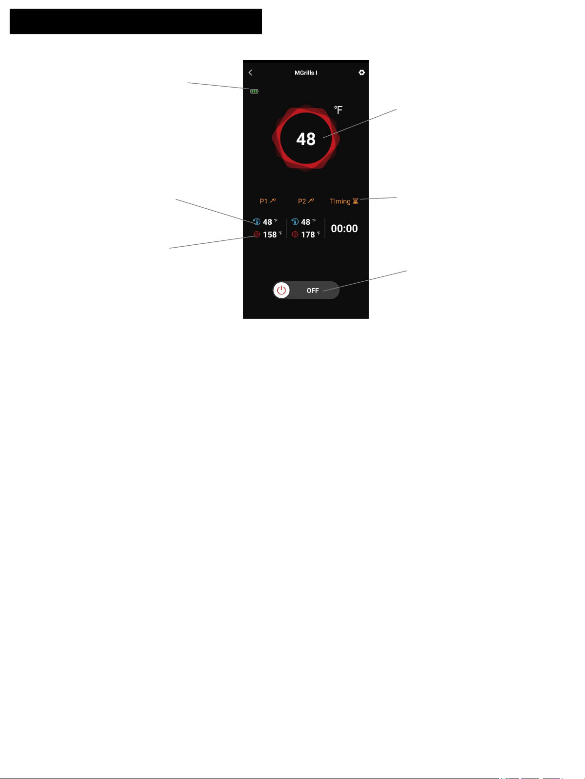
Firebox Real- time
Temperature Indicator
Meat Probe Timer
Meat Probe Real-time
Temperature Indicator
Meat Probe Target
Temperature Indicator
Battery capacity indicator
Turn off or Turn on the
Digitemp Display
2. Generate temperature curve
The APP will keep monitoring the firebox temperature and generate the temperature curve, click Firebox
Temperature Indicator on the screen to view the temperature curve. You can back to previous page by clicking
return icon “<” on the upleft corner.
1. Firebox Temperature Indicator
You can monitor the real-time fire box temperature in Firebox Temperature Indicator. This temperature data is not
adjustable by the APP or Digitemp Display.
3. Meat Probe Temperature Indicator
You can monitor the meat probe temperature and setup target temperature for two meat probes in Meat Probe
Indicator. Click P1 or P2 indicator area to setup the target temperature or you can choose type of meat and select
your preferred donness. There will be a beep from the phone to remind you when the target temperature is reached.
Monument App Instructions
4. Battery Capacity Indicator
You can monitor the battery capacity indicator, while the battary icon is flashing without any bars in the frame,
please replace the batteries with new.
26
To ensure a proper working unit the following proper care
and maintenance is suggested.
Cleaning Cooking Grids
We suggest you wash your cooking grids in a mild soap
and warm water solution. You can use a wash cloth or
soft brush to clean your cooking grids.
Cleaning Heat diffusers
Periodically you should wash the heat diffusers in a soap
and warm water solution. Use a soft brush to remove
stubborn burnt-on cooking residue. The heat diffusers
should be dry before you reinstall them.
Cleaning Grease Tray
The grease tray should be emptied and wiped down
periodically and washed in a mild detergent and warm
water solution. A small amount of sand or cat litter may be
placed in bottom of grease tray to absorb the grease.
Check the grease tray frequently, don’t allow excess
grease to accumulate and overflow out of the grease tray.
Annual Cleaning of Grill Interior
Burning-off the grill after every use will keep it ready for
your next use. However, once a year you should give the
entire grill a thorough cleaning to keep it in top operating
condition. Follow these steps.
1. Turn all burner valves to full OFF position.
2. Turn LP gas tank valve to full OFF position.
3. Detach LP gas hose and regulator assembly from your
gas grill. Inspect for any damage and replace as
necessary with manufacturer replacement part number
found on parts list.
4. Remove and clean heat diffusers, cooking grids and
grill burners.
5. Cover each gas valve orifice with aluminum foil.
6. Brush inside and bottom of grill with a nylon brush, and
wash with a mild soap and warm water solution. Rinse
thoroughly and let dry.
7. Remove the aluminum foil, then reinstall heat diffusers,
and cooking grids.
8. Reconnect gas source and observe burner flame for
correct operation.
Cleaning Exterior Surface
•We suggest you wash your grill using a mild soap and
warm water solution. You can use a wash cloth or sponge
for this process. Do not use abrasives or a brush that
might remove finish during the cleaning process.
Cleaning Exterior Stainless Steel Surfaces
•Weathering and extreme heat can cause exterior
stainless steel surfaces to turn tan in color.
Machine oils used in manufacturing process of
stainless steel can also cause this tanning color.
Use a stainless steel cleaner to polish stainless
steel surfaces of your grill. Never use abrasive
cleaners or scrubbers because they will scratch
and damage your grill.
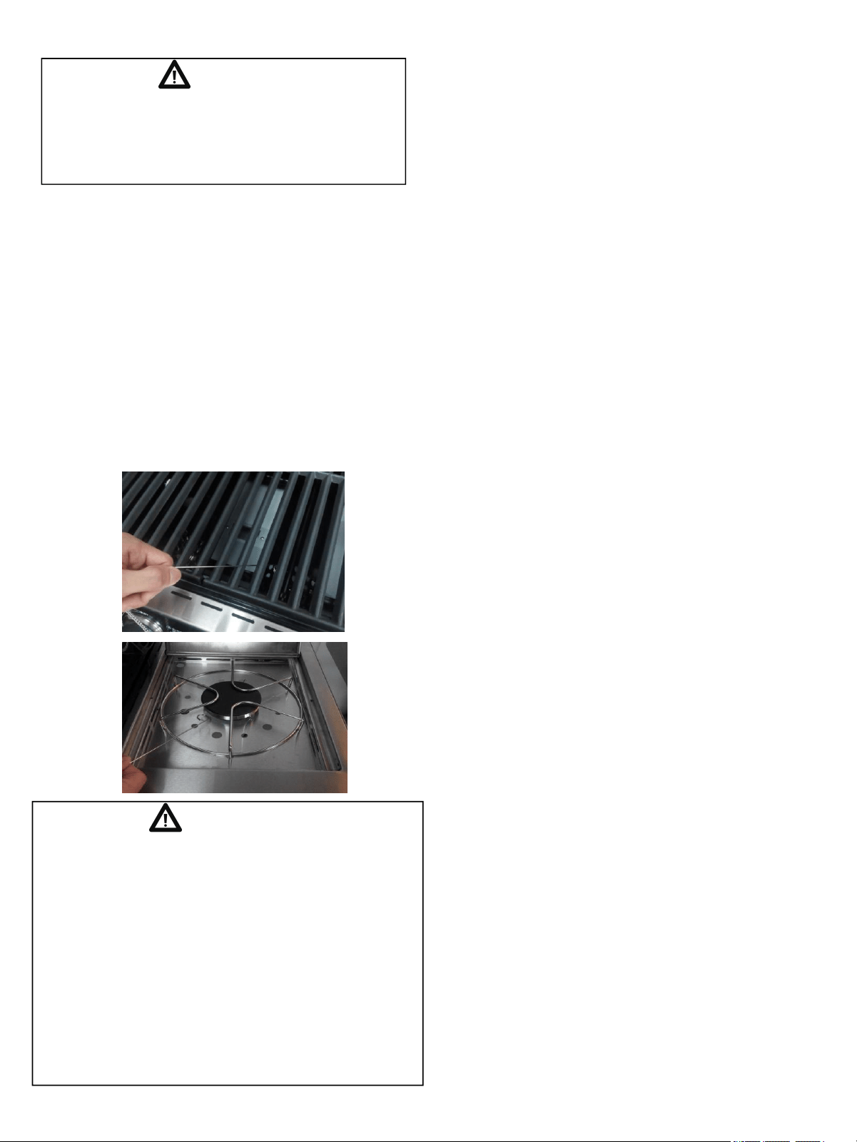
Cleaning Burner Tubes and Burner Ports
To reduce the chance of “FLASH-BACK” the
procedure below should be followed at least once a
month in late summer or early fall when spiders are
most active or when your grill has not been used for
a period of time.
1. Turn all burner valves and gas tank valve to off
position.
2. Detach the LP gas regulator assembly from your
gas grill.
3. Remove cooking grids, heat diffusers, and grease
tray from the grill.
4. Remove the screws from the underside of each
burner and lift the burners up and away from the gas
valve orifice.
5. Using a bent stiff wire in the shape of a hook , air
hose or a bottle brush, run it through the burner tube
and inside several times to remove any debris.
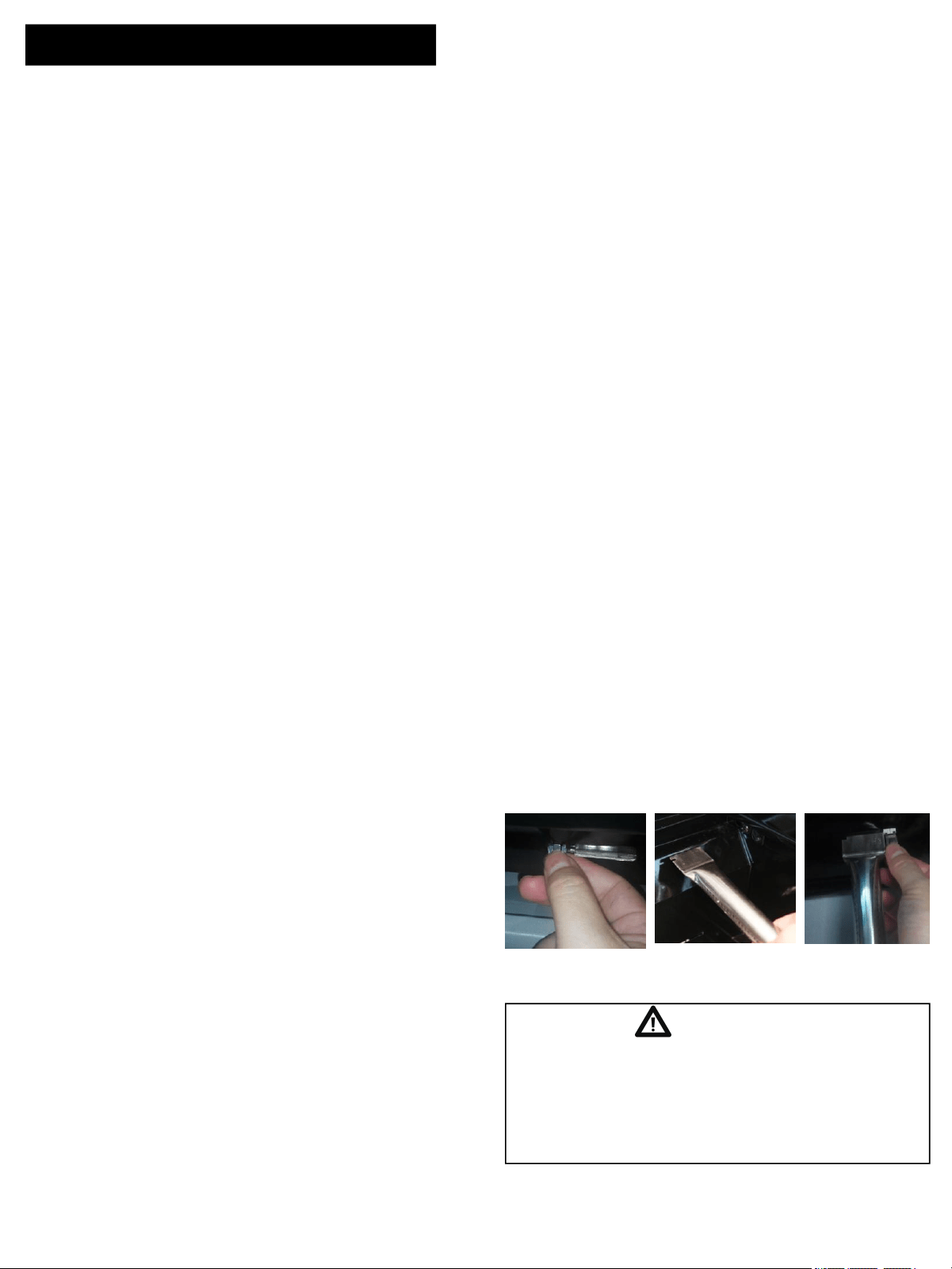
6. Replace burners, see illustration below.
WARNING
The location of the burner tube with respect to the
orifice is vital for safe operation. Check to ensure
the orifice is inside the burner tube before using
the gas grill. If the burner tube does not fit over the
valve orifice, lighting the burner may cause
explosion and/or fire.
Cleaning and Maintenance
Step 1 Step 2 Step 3
27
BEFORE CALLING FOR SERVICE
If the grill does not function properly, use the following check list before calling for service.
You should inspect the burners at least once a year or immediately after any of the following
conditions occur:
Regardless of which burner cleaning procedure you
use, we recommend you also complete the following
steps to help prolong burner life.
1. Use a fiber pad or nylon brush to clean the entire
outer surface of each burner until free of food residue
and dirt.
2. Clean any clogged ports with a stiff wire, such as
an open paper clip.
WARNING
Spiders and insects can nest inside the burners of
the grill and disrupt gas flow. This very dangerous
condition could cause a fire behind the valve panel,
thereby damaging the grill and making it unsafe
for operation. Inspect the grill at least twice a year.
3. Inspect each burner for damage (cracks or holes)
and if such damage is found, order and install a new
burner. After installation check to ensure that gas
valve orifices are correctly placed inside the ends of
the burner tubes.
Troubleshooting
PROBLEMS WHAT TO DO
Low heat with knob in “HI” position.
Grill won’t light when the control
knob is rotated.
Burner flame is yellow or orange, in
combination with the odor of gas.
l Check to see if LP tank is empty.
l Clean wires and/or electrode by rubbing with
alcohol and clean swab.
l Wipe with dry cloth.
l Make sure the wire is connected toelectrode
assembly.
l Check to see if other burners operate. If so,
check the gas orifice on the malfunctioning
burner for an obstruction.
l Refer to Clean Burner Tubes and Burner Ports
on page 26. If problem still exists,please
contact us.
l Is the fuel hose bent or kinked?
l Is the grill in a dusty area?
l Is there adequate gas supply available?
l If it is only one burner that appears low,does
the orifice or burner need cleaning?
l Is the gas supply or gas pressure low?
l Dis-connect the probe wire and connect again.
l If re-connect is not work, please contact our
service center.
Error Code “ERP”
28
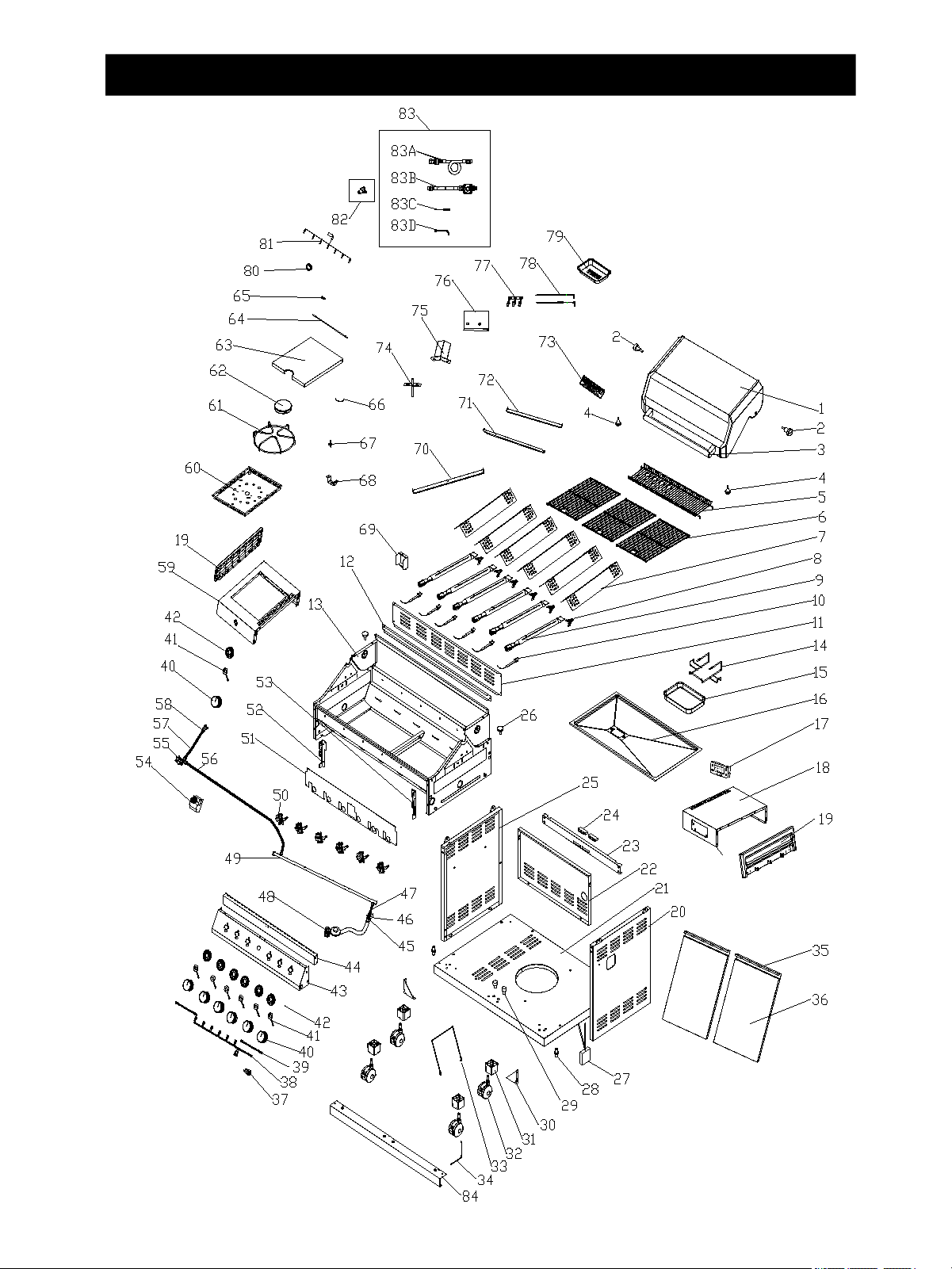
Model Denali 605 Parts Diagram
PSIG GLO BA L Q
C
LOW
29
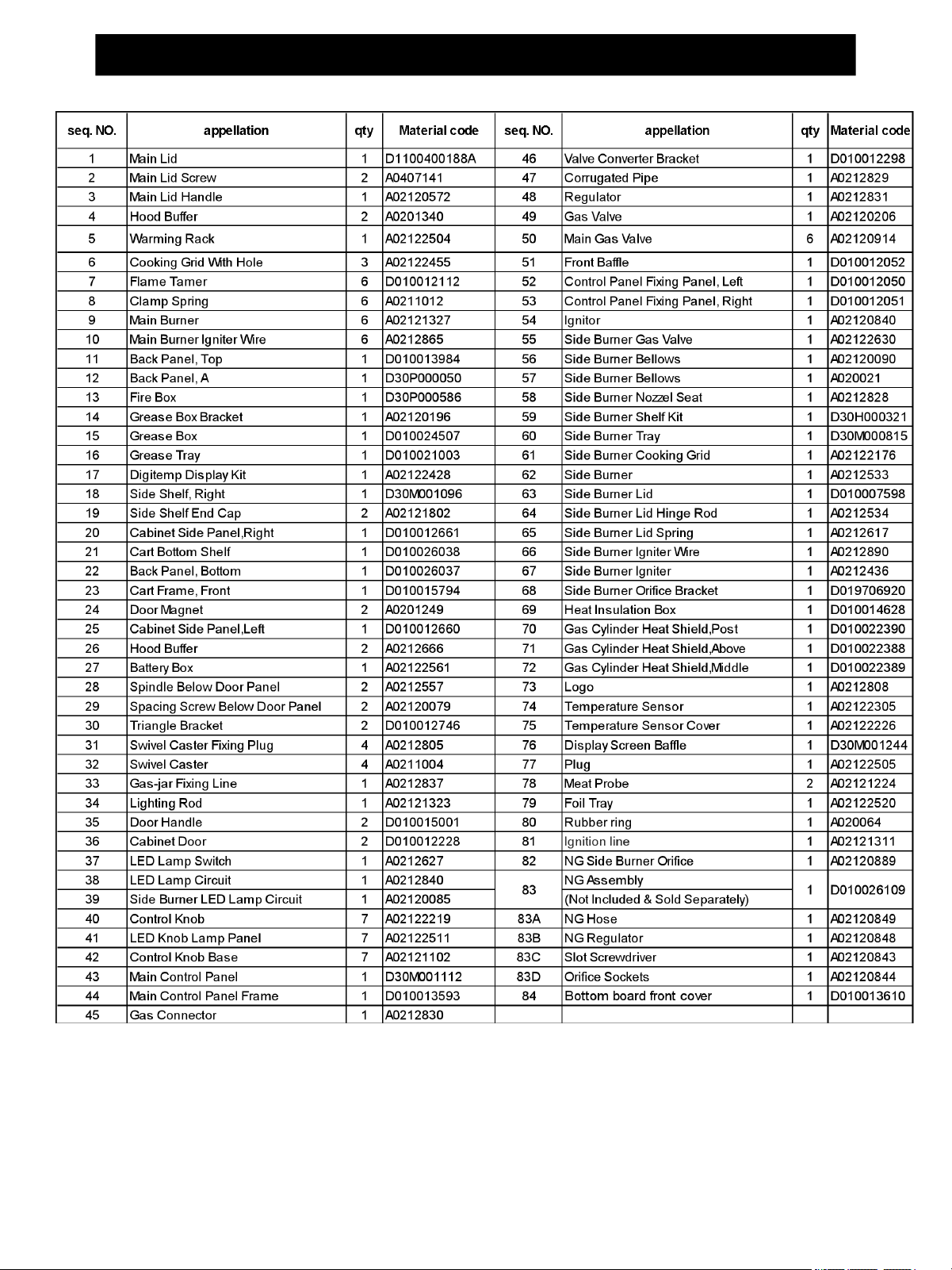
Model Denali 605 Parts List
To make sure you obtain the correct replacement
parts for your gas grill, please refer to the part
numbers on this page.
Important: Use only parts listed above. When
ordering parts, providing the following information:
1. Model #
2. Part Number (see PART# in chart)
3. Part Description
4. Quantity of parts needed
Important: Keep this Owner’s Manual for
convenient reference and for part replacement.
30
WARNING
Do not leave the grill unattended.
Your grill will get very hot.
Cooking Instructions
Burn-off
Before cooking on your gas grill for the first time,
you will want to “burn off” the grill to eliminate any
odor or foreign matter. Just ignite the burners,lower
the Lid, and operate grill on the HIGH setting for 3
to 5 minutes.
Cooking Temperatures
High setting: Only use this setting for fast warm-
up,searing steaks or chops and for burning food
residue off the grill after cooking is complete.
Never use the HIGH setting for extended cooking.
Medium to Low Settings: Most recipes specify
medium to low settings, including all smoking,
rotisserie cooking and for cooking lean cuts such
as fish.
NOTE: Temperature settings will vary with the
temperature and the amount of wind outside your
home.
Direct Cooking
The direct cooking method can be used with the
supplied cooking grids and food placed directly
over the lit grill Burners. Direct cooking requires
the grill lid to be up.The method is ideal for
searing and whenever you want meat, poultry or
fish to have and open-flame barbecued taste.
Deep frying and smoking are also best cooked in
this manner because they require direct heat.
Indirect Cooking
To cook indirectly, the food should be placed on the
left or right side of your grill with the burner lit on the
opposite side. Indirect cooking must be done with
the Lid down.
Flare-ups
The fats and juices dripping from grilled food can cause
flare-ups. Since flare-ups impart a favorably,distinctive
taste and color to food cooked cover an open flame,
they should be accepted up to a point. Nevertheless,
uncontrolled flaring can result in a ruined meal.
WARNING
Do not line the bottom of the grill housing with
aluminum foil, sand or any substance that will
restrict the flow of grease into the grease tray.
Failure to comply with these instructions could
result in a fire or explosion which could cause
serious bodily injury, death, or property damage.
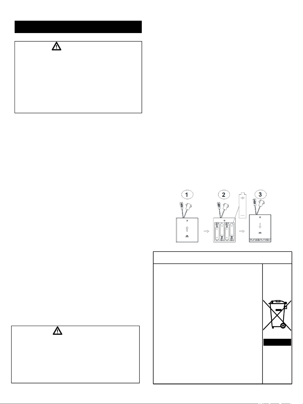
Replacing the Battery
If the LED do not light, the battery should be replaced.
Change the led battery.
1. Find the battery box,open the lid.
2. Put 4pcs “AA” size battery,the positive and negative
pole of the battery should keep the same as the pole
in box.
3.Close the lid.
Correct Disposal of this product
Never lean over the cooking area while using
your grill. Do not touch cooking surfaces, grill
housing. Grill Lid or any other grill parts while the
grill is in operation, or until the grill has cooled
down after use. Failure to comply with these
instructions may result in serious bodily injury.
This marking indicates that this product
should not be disposed with other
household wastes throughout the EU. To
prevent possible harm to the environment
or human health from uncontrolled waste
disposal, recycle it responsibly to
promote the sustainable reuse of material
resources. To return your used device,
please use the return and collection
systems or contact the retailer where the
product was purchased. They can take
this product for environmental safe
recycling.
31
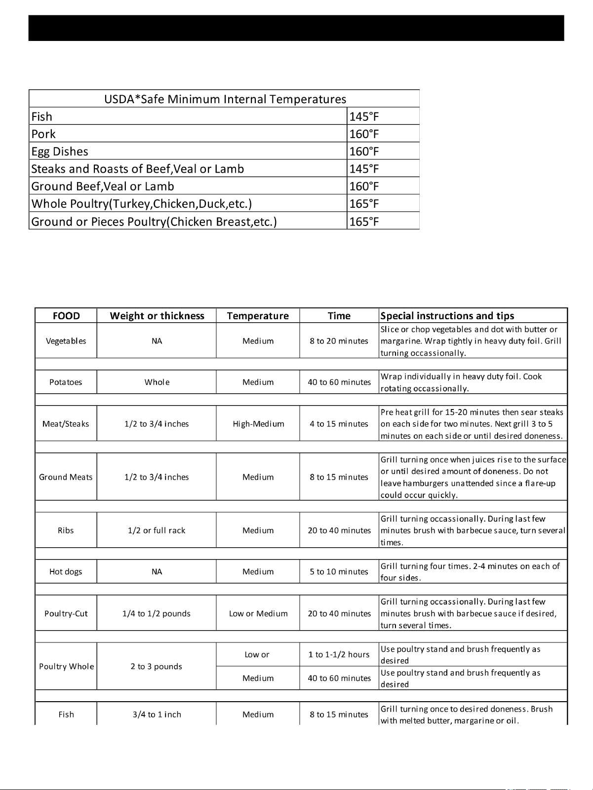
Grill Cooking Chart
WARNING: To ensure that it is safe to eat,food must be cooked
to the minimun internal temperatures listed in the table below.
*United States Department of Agriculture
32
Natural Gas Conversion
(Not Included & Sold Separately)
Warranty
One-Year Full Warranty on Part
If this part fails due to defective material or workmanship within one year from the
date of purchase, please contact us to arrange for a free repair (or replacement if
repair proves impossible)
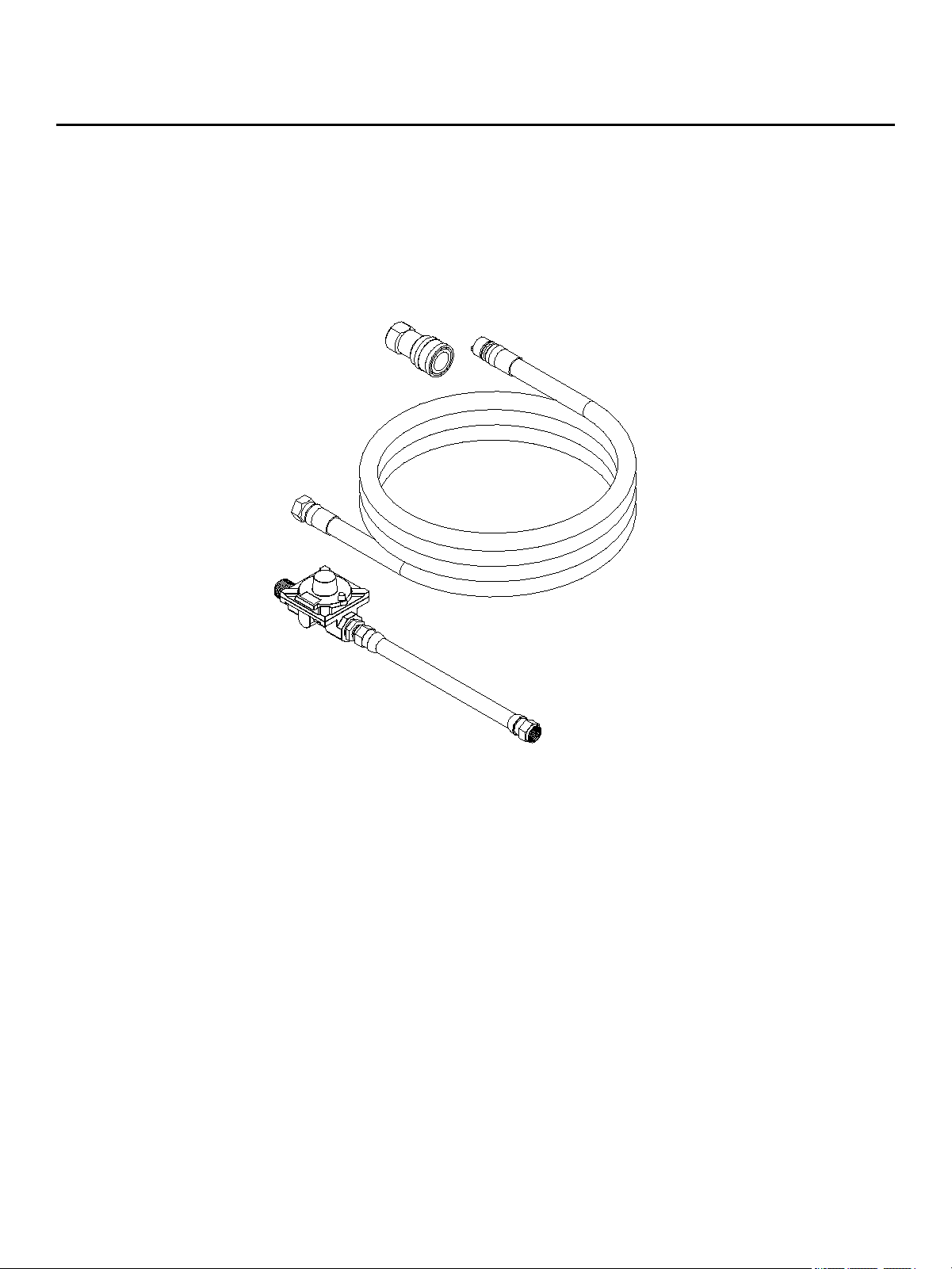
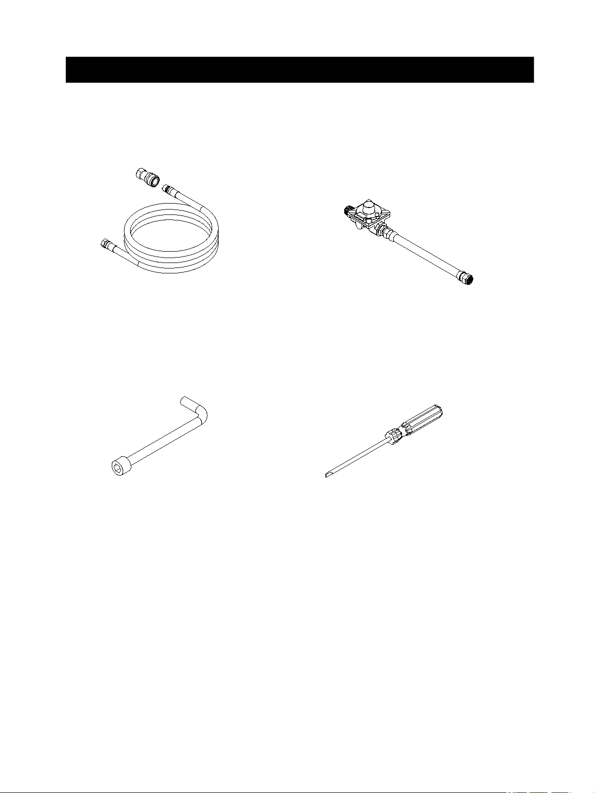
Natural Gas Conversion Kit
33
NG Hose +Quick Connector
A02120849
NG Regulator
A02120848
6mm
Orifice Sockets
A02120844
Slot Screwdriver
A02120843
Parts List
Reminder:
Please keep the main burner brass LP orifices ,Side Burner Orifice
and original LP regulator. Just in case you want to change back
from Natural Gas(NG) to Liquid Propane(LP)
34
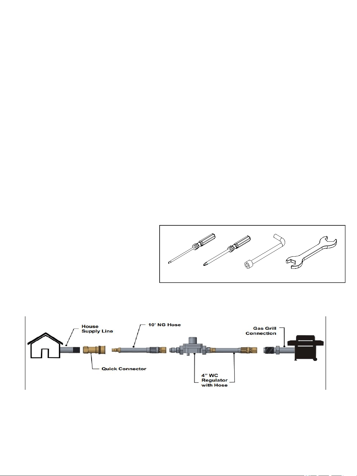
Tools will be needed for gas conversion
Natural Gas Conversion
WARNING! FAILURE TO READ THESE WARNINGS COULD RESULT IN A FIRE OR
EXPLOSION THAT COULD CAUSE SERIOUS BODILY INJURY, DEATH OR PROPERTY
DAMAGE.
Natural Gas Conversion must be performed by a QUALIFIED GAS TECHNICIAN ONLY.
The QUALIFIED GAS TECHNICIAN should ensure compliance of local codes, including but
not limited to, requirements and installation of grill regulator.
DO NOT ATTEMPT TO CONVERT YOURSELF. Improper conversion could result in a gas
leak which could cause a fire or explosion and cause serious bodily injury, death or property
damage. Leaks due to improper conversion could occur immediately or slowly over time. If
you hear any unusual noises or leaks, smell gas or unusual odors, or notice anything unusual
with the operation of your gas appliance after the installation immediately shut off the gas
supply and discontinue use until the appliance is repaired by a QUALIFIED
GASTECHNICIAN.
Below parts are needed for natural gas conversion:
INCLUDED
§Natural gas orifices(Preinstalled In Grill)
§Quick Connector
§10 ft (3.0m) Natural Gas Hose
§4” Water Column Regulator with Hose
§Orifice Sockets
§Slot screwdriver
NOT INCLUDED
§House Supply Line
§Wrench
§Philips screwdriver
Included
Included
Not Included
Not Included
35
1. Turn off the main gas supply valve.
2. Disconnect LP gas fuel tank (if present).
3. Turn off all burner control valves.
4. Remove the LP gas fuel tank (if present) from the grill cart.
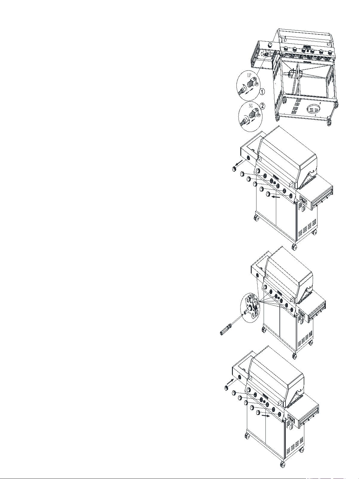
5. Use an adjustable wrench to remove the LP regulator from the manifold.
6.Use an adjustable wrench to install the Natural gas
regulator hose to the manifold and secure
Label position
7.After LP is converted to NG, you need to put a label on
the location shown below.
Reminder:
Please keep the original LP regulator.
Just in case you want to change back from NG to Propane.
LP to NG step
36
1.Pass the NG hose to grill cart through the back panel
2.Connect the brass connector on one end of
the 10 ft (3.0m) PVC flexible gas supply hose to
the Natural gas pressure regulator
3.Connect the quick connector on the other end of the 10
ft (3.0 m) PVC flexible gas supply hose to the rigid
Natural gas supply pipe.
4.Please do leak test after conversion
Make Gas Connection
P
S
I
G
G
L
O
B
A
L
Q
C
L
O
W
P
S
I
G
G
L
O
B
A
L
Q
C
L
O
W
37
1:Removee all the control knobs
Adjust High/Low Flame Setting Screw
2:Use a flat-blade screwdriver to turn the high flame
setscrew clockwise approximate 90º
4:Replace the control knob and turn off the burner
3:Check that burner operates at the new high flame
setting. It may be necessary to adjust the screw setting
slightly more to get the ideal burner flame
height
Removee the LP Side Burner Orifice,and install
the NG Side Burner Orifice
Change the Side Burner Orifice
The NG Side Burrne Orifice is packed in grill with
individual bag marked for NG gas conversion only.
Reminder:
Please keep the LP Side Burner Orifice.
Just in case you want to change back from NG to Propane.
38
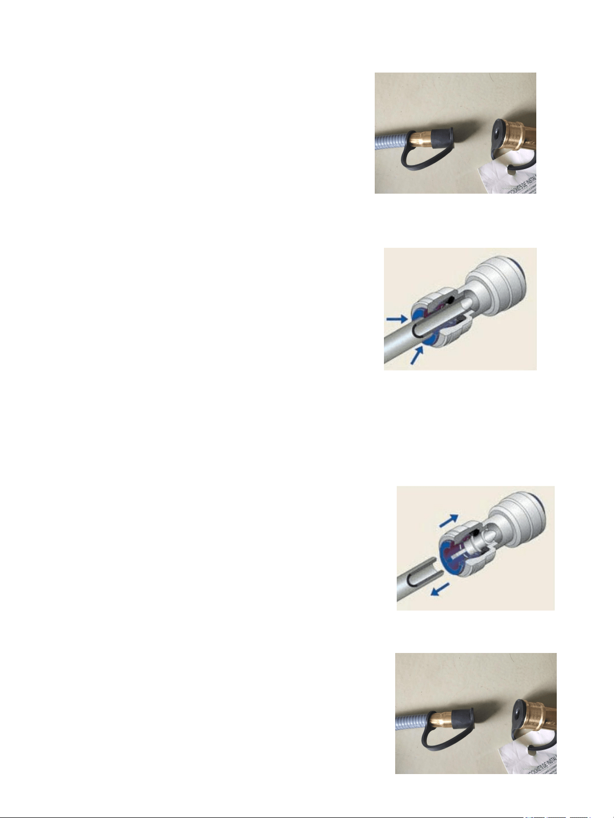
1. Inspect the valve to ensure that the
external mating threads are correct to fit the
hose and regulator assembly provided.
2. Make sure all burner valves are in the
closed position.
3. Check valve connection port and
regulator assembly. Look for damage or
debris. Remove all debris. Inspect the hose
for damage. Never use damaged or blocked
equipment.
4. Remove the plug from the quick
connector.
5. Pull the snap ring back and plug in the
connector.
6. Loosen the quick snap ring and confirm
whether the connection is secure.
7. Open the natural gas valve fully
(counterclockwise). Before attempting to
ignite the grill, use a soapy water solution to
check all connections for leaks. If a leak is
found, close the valve and do not use the
grille before repairing the leak.
Note: When not using the product, the air
supply valve must be closed.
Gas oven connection quick connector
Gas oven disassembly quick connector
1. Make sure the gas pipeline valve is in the closed
position.
2. Make sure all burner valves are in the closed
position.
3. Pull the quick snap ring backwards and
simultaneously pull the connected trachea
backwards.
4. Use a plug to plug the port of the quick connector
to prevent foreign objects from entering the air pipe.
39
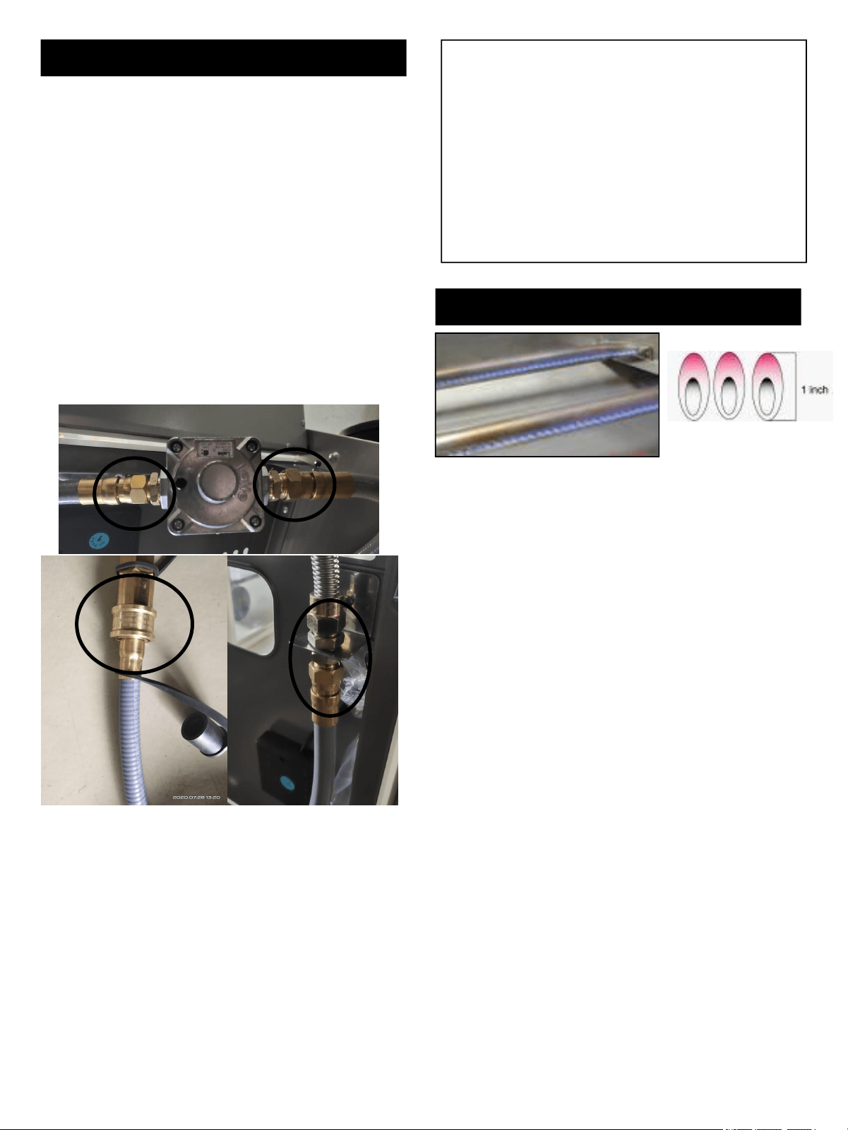
Visually check the burner flames prior to each use. The
flames should look like picture, if they do not, refer to the
cleaning burner tubes and ports, see page 26 of this
manual.
Requiring the grill can be connected to the gas supply by
means of a flexible hose connector complying with the
current Standard
for Elastomeric Composite Hose and Couplings for
Conducting Propane and Natural Gas, CAN/CGA-8.1
or with the Standard for Thermoplastic Hose and Hose
Couplings for Conducting Propane and Natural
Gas, CAN1-8.3
Burner Flame Check
Congratulations
Your gas grill is now ready for use. Before first
use and before the beginning of each season
(and when the pressure regulator is replaced or
installed):
1. Read all safety, lighting and operating
instructions.
2. Check the gas valve hole, burner tube and
burner port for obstructions.
3. Perform a gas leak check according to the
instructions in the manual.
Check for gas leaks
Check the hose before using the outdoor cooking
gas appliance. If there is a significant excessive
wear or wear, or if the hose is cut, it must be
replaced before the outdoor cooking gas appliance
is put into operation. Replace the hose assembly
as specified by the manufacturer.
1. Make a 50/50 (soap / water) mild soap solution.
2. open the door
3. Turn the control knob to the fully closed position;
then open the valve of the natural gas pipeline.
4. Apply soap solution to all gas connections with
a clean brush. as follows. If air bubbles appear in
the solution, the connection is not properly sealed.
Inspect each accessory and tighten or repair as
needed.
5. If your gas connection leaks and you will not be
able to repair it, turn off the gas in the gas supply
tank, disconnect the fuel pipe from the grill, and
call your gas supplier for repair assistance.