E3788-1
Rev C 3/3/25
Engineering and technical data are subject to change without notice.
FEDERAL INDUSTRIES 215 Federal Ave Belleville, WI 53508
INSTALLATION & OPERATIONS INSTRUCTIONS
ITH: Heated Models

E3788-1 Rev A - ITH 2
CONTENTS
(1) Introduction ............................................................................................................................................................. 3
1.1 Serial Number ................................................................................................................................................ 3
(2) Warning Labels & Safety Instructions ..................................................................................................................... 4
(3) Prior To Unpacking Equipment! .............................................................................................................................. 5
(4) General Electrical & Grounding .............................................................................................................................. 6
4.1 Cord Connected ............................................................................................................................................. 6
(5) Installation Instructions ........................................................................................................................................... 7
5.1 Locating The Display Case ............................................................................................................................ 7
5.2 Removing Case From Shipping Skid ............................................................................................................. 7
5.3 Single Case Installation (Stand alone units) .................................................................................................. 7
5.4 Prior to Initial Use ........................................................................................................................................... 8
(6) Compartment Panel Removal ................................................................................................................................. 9
Top Cover .................................................................................................................................................................. 10
(7) End Panel Installation ........................................................................................................................................... 11
(8) Shelving Installation and Removal ........................................................................................................................ 12
8.1 Shelf Brackets and Supports........................................................................................................................ 12
(9) Front And Rear Doors Removal ........................................................................................................................... 16
(10) Control Operation ............................................................................................................................................. 18
10.1 Air Temperature Control ............................................................................................................................... 18
10.2 Humidity Control And Pan Operation (When Equipped) .............................................................................. 20
10.3 Typical Humidity Conditions ......................................................................................................................... 21
(11) Food Packaging Recommendations ................................................................................................................ 22
(12) Initial Startup ..................................................................................................................................................... 23
12.1 Startup .......................................................................................................................................................... 23
12.2 Placing Product into Case ............................................................................................................................ 23
(13) Cleaning Instructions ........................................................................................................................................ 24
13.1 Daily Cleaning .............................................................................................................................................. 24
13.2 Weekly Cleaning .......................................................................................................................................... 24
13.3 Cleaning The Optional Humidity Pan ........................................................................................................... 25
(14) Service .............................................................................................................................................................. 27
(15) Sale & Disposal ................................................................................................................................................ 28
15.1 Owner Responsibility ................................................................................................................................... 28
(16) Troubleshooting ................................................................................................................................................ 29
(17) Service Parts .................................................................................................................................................... 31
E3788-1 Rev A - ITH 3
(1) Introduction
Thank you for purchasing a Federal Industries display case. This manual contains important
instructions for installing and servicing your new display case. A repair parts list and wiring
diagram are also included in the manual. Read all of these documents carefully before installing
or servicing your case.
NOTICE
Read this manual before installing your case. Keep this manual and
refer to it before doing any service on the equipment. Failure to do so
could result in personal injury or damage to the case.
NOTICE
Installation and service of the electrical components in the case must
be performed by a licensed electrician.
The portions of this manual covering components contain technical
instructions intended only for persons qualified to perform electrical
work.
DANGER
Improper or faulty hookup of electrical components in the case can
result in severe injury or death.
All electrical wiring hookups must be done in accordance with all
applicable local, regional, or national standards.
1.1 SERIAL NUMBER
Record the model and serial numbers of the case for easy reference. Always refer to both model
and serial numbers in your correspondence with Federal regarding the case.
Case Model__________________________ Serial Number______________________
This manual cannot cover every installation, use, or service situation. If you need additional
information, call or write us:
WARRANTY/TECHNICAL SERVICE DEPARTMENT
Parts Town
1200 Greenbriar Dr.
Addison, IL 60101
Toll Free: (833) 238-8168
Email: [email protected]
E3788-1 Rev A - ITH 4
(2) WARNING LABELS & SAFETY INSTRUCTIONS
This is the safety-alert symbol. When you see this symbol on your
case or in the manual, be alert to the potential for personal injury or
damage to your equipment.
Be sure you understand all safety messages and always follow recommended precautions and
safe operating procedures.
NOTICE TO EMPLOYERS:
You must make sure that everyone who installs, uses, or services your
case is thoroughly familiar with all safety information and procedures.
Important safety information is presented in this section and throughout the manual. The
following signal words are used in the warning and safety messages:
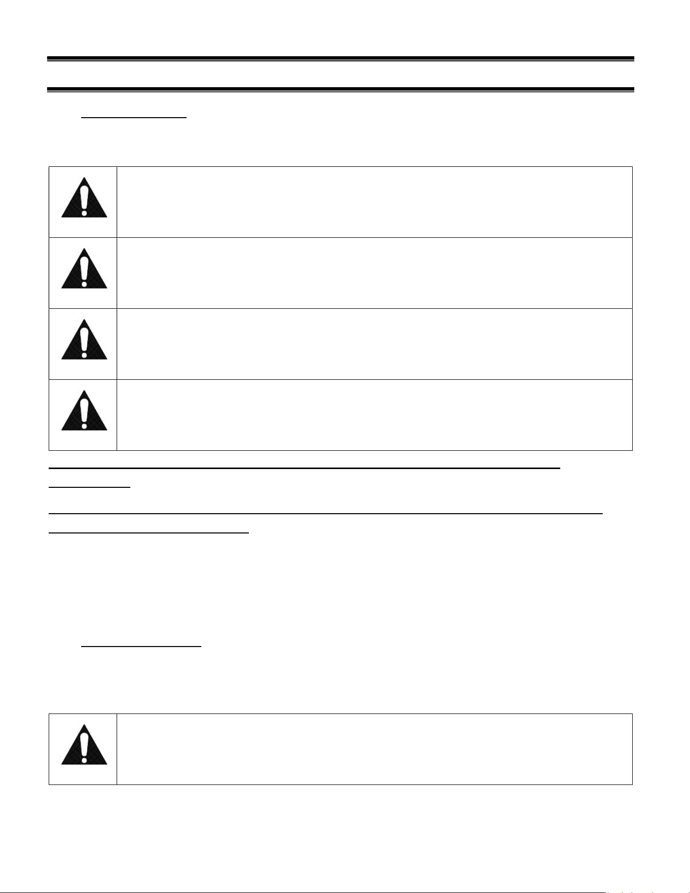
DANGER: Severe injury or death will occur if you ignore the message.
WARNING: Severe injury or death can occur if you ignore the message.
CAUTION: Minor injury or damage to your case can occur if you ignore the message.
NOTICE:
This is important installation, operation, or service information. If you ignore the
message, you may damage your case.
The warning and safety labels shown throughout this manual are placed on your Federal
Industries case at the factory. Follow all warning label instructions. If any warning or safety labels
become lost or damaged, call our customer service department at (800) 356-4206 for
replacements.
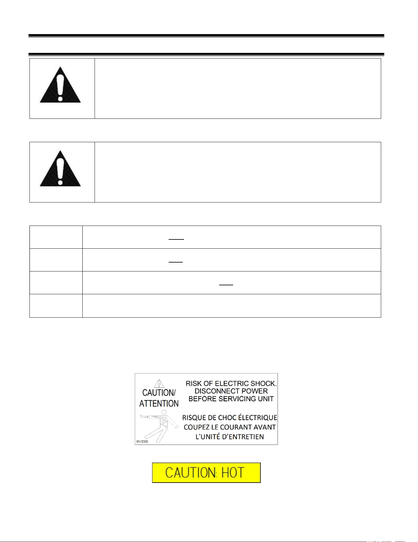
Located at front of unit and on shelves

E3788-1 Rev A - ITH 5
(3) PRIOR TO UNPACKING EQUIPMENT!
Inspect for shipping damage.
You are responsible for filing all freight claims with the delivering truck line. Inspect all
cartons and crates for damage as soon as they arrive. If damage is noted to shipping crates,
cartons, or if a shortage is found, note this on the bill of lading (all copies) prior to signing.
If damage is discovered when the case is uncrated, immediately call the delivering truck line
and follow-up the call with a written report indicating concealed damage to your shipment.
Ask for an immediate inspection of your concealed damaged item. Crating material must be
retained to show the inspector from the truck line.
E3788-1 Rev A - ITH 6
(4) GENERAL ELECTRICAL & GROUNDING
WARNING:
Improper or faulty hookup of electrical components in the display case
can result in severe injury or death.
4.1 CORD CONNECTED
For models that are supplied with a power cord, the cord is properly sized to the amperage
requirements of the case. See the rating plate for specific unit requirements.
CAUTION
Risk of Electric Shock. If the cord or plug becomes damaged, replace
only with a cord and plug of the same type.
E3788-1 Rev A - ITH 7
(5) INSTALLATION INSTRUCTIONS
5.1 LOCATING THE DISPLAY CASE
The case must be located where it is not subjected to the direct rays of the sun, heating ducts,
grills, radiator, or ceiling fans, nor should it be located near open doors or main door entrances.
Also, avoid locations where there are excessive air movement or air disturbances.
There are no special clearance requirements for this unit.
5.2 REMOVING CASE FROM SHIPPING SKID
Be sure to leave shelf packaging material intact for this step.
First remove the base front and rear panels
Two or more people should be involved in moving the unit from the pallet onto the ground.
Remove the (4) 1/4” screws that secure the case to the skid. These screws are located in the
front and rear corners of the base rails inside of the front and rear base access panels/grills.
Once all the bolts are removed, slide the unit off the back of the shipping pallet, and tilt it so the
rear corner touches the ground. Then have someone move pallet out from under the case and
gently tilt the case forward until it touches the floor.
5.2.1 Removing Packaging Material
Remove bubble wrap and packing material for all shelves and panel, brackets, etc. If it is
necessary to remove tape residue from plastic materials, use cleaning compounds
recommended in the cleaning section of this manual.
5.2.2 Lifting and Moving the Case
Caution:
Do not push or pull against the top end glass, or door frames and do not
pull on end panels when removing the case from the skid or moving the
case. Case damage or glass breakage will result.
5.3 SINGLE CASE INSTALLATION (STAND ALONE UNITS)
NOTE: If necessary, use a wood or plastic shim under each leg leveler to avoid scratching the
tile floor.
5.3.1 Sealing Unit to The Floor
After the unit is positioned and the leg levelers are turned out, the unit needs to be sealed to the
floor for NSF approved installation. This is not required for models with casters or legs.

E3788-1 Rev A - ITH 8
5.4 PRIOR TO INITIAL USE
Unit must be cleaned as indicated in the “WEEKLY CLEANING” section of this manual before
initial use.
E3788-1 Rev A - ITH 9
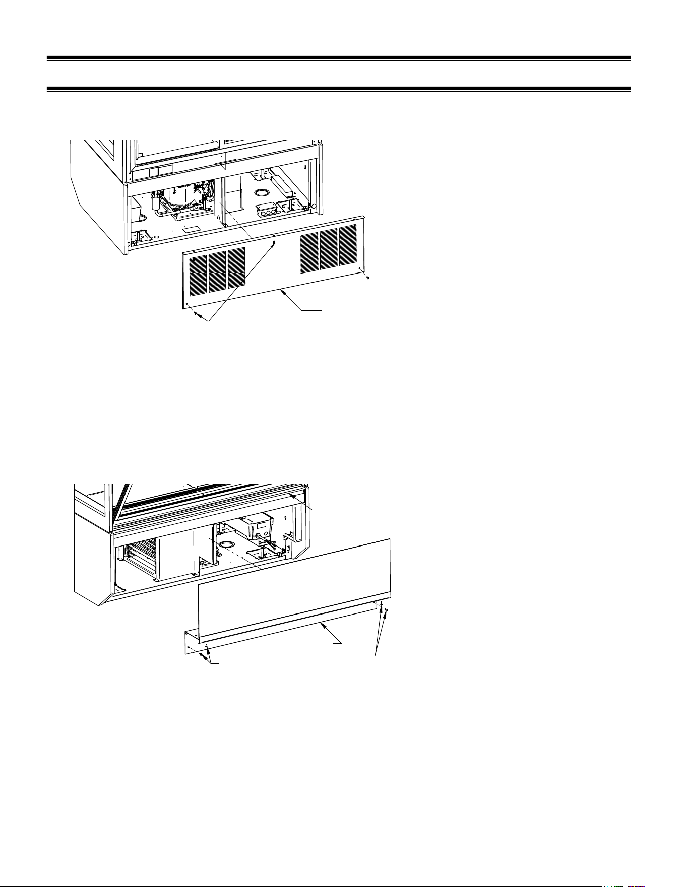
(6) COMPARTMENT PANEL REMOVAL
Floor Base Models Back Panel
REAR BASE PANEL
REAR BASE PANEL
SCREWS
1. Remove screws located in each lower corner of panel.
2. Remove screws located on top of panel under the base cross member.
3. Pull top of panel outward until lip on bottom of panel clears bottom of base and remove
from case.
Front Panel
FRONT PANEL
SCREWS
FRONT PANEL
FRONT PANEL
SCREWS
TOP PANEL
RETAINER
1. Disconnect power to Display Case.
2. Remove (2) front panel phillip head screws from each lower corner of front panel (1) is
located on front of panel and the other under the recess behind trim strip. Do not remove
the screws holding trip strip to front panel.
3. Slide the front panel down until it slides out of the top panel retainer lip at the top of the
panel.
4. Install panel in reverse order.
E3788-1 Rev A - ITH 10
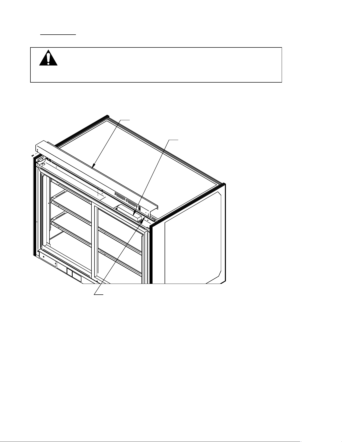
TOP COVER
Light Power Supply is located on top of case under the top cover.
(4) TOP COVER SCREWS
TOP COVER
LIGHT POWER
SUPPLY
1. Disconnect power to Display Case.
2. Remove the (4) 8-32 top cover screws from top cover.
3. Slide the cover back from under the top glass trim.
Note: there is a ground wire connected from case to the Top Cover. To prevent
electrical shock Do NOT remove this wire.
DANGER: Electric shock hazard. Do not operate unit with panels
removed.
E3788-1 Rev A - ITH 11
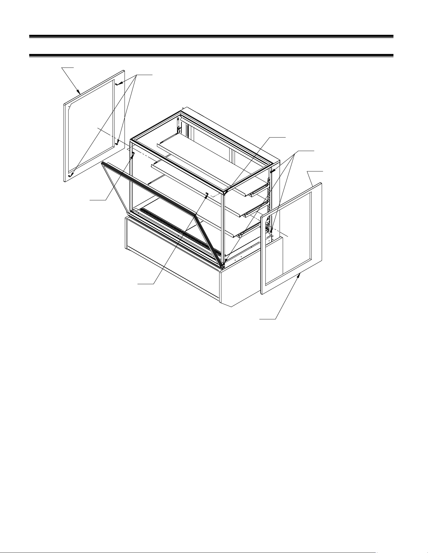
(7) END PANEL INSTALLATION
(3) THUMB SCREWS
1/4-20 X .5LG
(1) THUMB SCREW
1/4-20 X .5LG
(1) THUMB SCREW
1/4-20 X .5LG
(3) THUMB SCREWS
1/4-20 X .5LG
RIGHT END
PANEL
LEFT END
PANEL
(3) KEY SLOTS
(1) HOLE
End Glass is shipped installed on Floor model units.
1. On each side of case there are (3) keyhole mounting slots for easier installation of glass.
There is (1) mounting hole in the front top corner of case to prevent glass from accidently
popping off of end of case.
2. Screw (3) thumb screw about half way into end panel in location of the keyholes in case as
shown.
3. Align end panel thumb screws with keyholes and hook end panel on to case. Do not
tighten thumb screws.
4. Align the mounting hole in top front corner of case with top front hole in end panel and
attach with ¼-20 x .5LG thumb screw
5. Tighten all (4) thumb screws by hand.
6. Remove end panels in reverse order.
E3788-1 Rev A - ITH 12
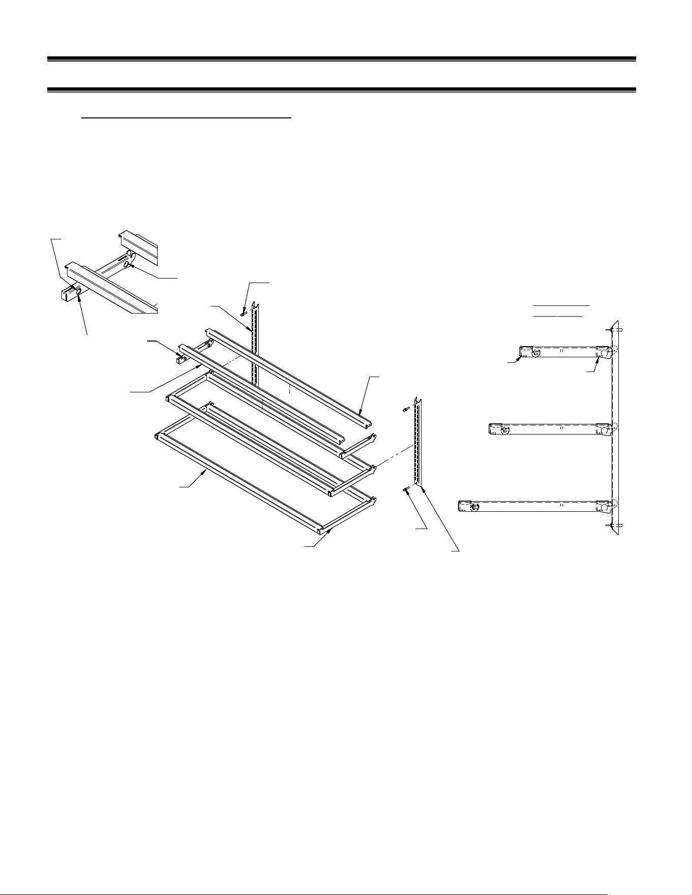
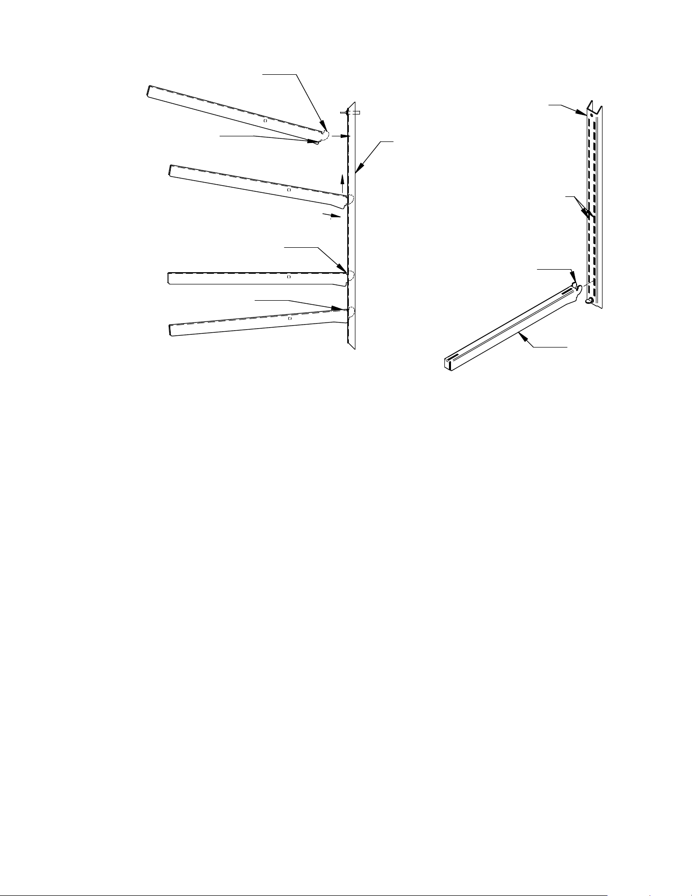
(8) SHELVING INSTALLATION AND REMOVAL
8.1 SHELF BRACKETS AND SUPPORTS
NOTE: Different shelf sizes and quantities are optional from factory so shelf bracket quantity and
size may vary, but procedure is the same.
FRONT
SUPPORT
W/LED LIGHT
TYPICAL SHELF
ARANGEMENT
SHELF BRACKET
WITH 1/2" CORD
HOLES
CORD IN HOLE
CORD OUT
HOLE
FRONT SHELF
SUPPORT
WITH LIGHT
SHELF STANDARD
RETAINING SCREWS
SHELF STANDARD
REAR SHELF
SUPPORT
SHELF BRACKET
NO CORD HOLES
GLASS SHELF
PRODUCT STOP
SHELF
STANDARD
SHELF STANDARD
RETAINING SCREWS
FRONT SHELF
SUPPORT
1. Turn the light switch to the off position. Remove rear doors as described in the “Rear Door
Removal” section of this manual to allow access to interior of case.
2. Follow the instruction in the illustration below. Starting with the longest brackets for bottom
shelf insert (1) of the (2) shelf brackets in the desired shelf standard slot on one side of the
case. Place the long second shelf bracket in the same shelf standard slot on the opposite end
of case. Important; The bracket with the ½ hole must be on the light cord side of case.
3. Repeat procedure for middle shelf brackets and the shortest top brackets. NOTE: Different
shelf sizes and quantities are optional from factory so shelf bracket quantity and size may
vary, but procedure is the same.
1. Tilt shelf bracket upward and install shelf bracket hook into desired slot.
2. Lift shelf bracket hook up behind back of shelf standard and rotate the shelf bracket
downward until desired shelf bracket tab rests on front of shelf standard.
3. Bracket can be either flat 0 degrees 5 degree downward tilt as shown.
E3788-1 Rev A - ITH 13
1.
2.
3.
SHELF
STANDARD
SHELF
STANDARD
SHELF
BRACKET
SHELF BRACKET HOOK
HOOK
SHELF
STANDARD
SLOT
FLAT SHELF POSITION
5
v
SHELF POSITION
SHELF BRACKET TAB
0 AND 5
v
4. Once all shelf brackets are installed in desired position run each shelf light cord into ½ hole in
back of shelf bracket and out the ½” hole in the front of shelf bracket. The shelf light cord
length can be adjusted by pulling out cord from cord grommet or pushing cord back into cord
grommet.
5. Install front shelf supports with LED lights on to shelf brackets. All shelf supports with the
lights are the same. The LED light must be facing towards back of case. Hook shelf support
end flanges into front notch of shelf brackets on each side of case.
6. Install rear shelf supports with no lights on to shelf brackets. All shelf supports with no lights
are the same. The flange on shelf support should be facing towards back of case. Hook shelf
support end flanges into rear notch of shelf brackets on each side of case
7. Push shelf light cords into end of LED light. NOTE: Do not plug cord in backwards. There are
(2) humps on end of cord that must align with humps in end of LED light. Plugging in the cord
upside down will Damage LED light strip.
8. Manage desired cord lengths by pulling out cord from cord grommet or pushing cord back into
cord grommet.
NOTE: Cords always remain in case they are not removable.
E3788-1 Rev A - ITH 14
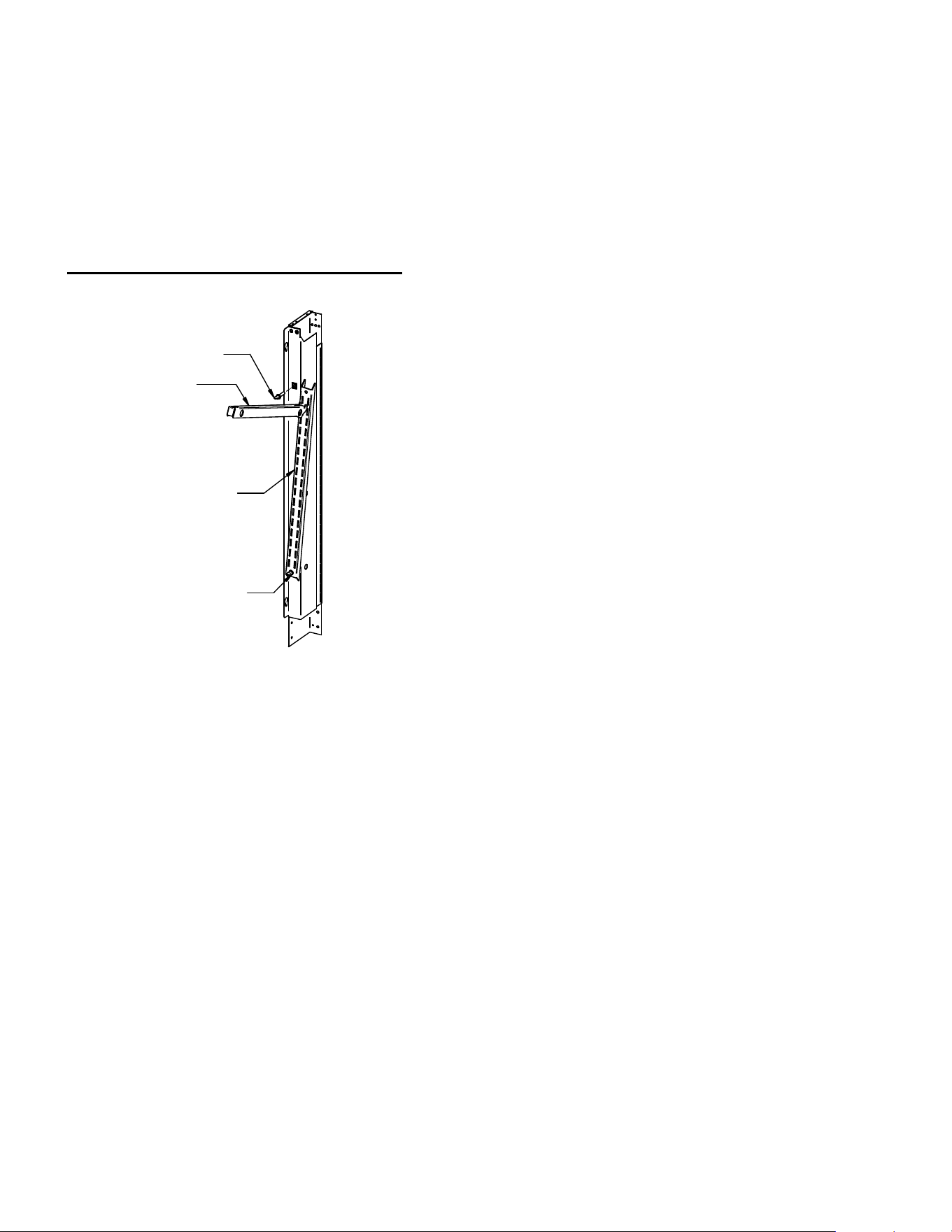
Special Length Shelf Installation
LONG SHELF BRACKET
TOP THUMB SCREW
LOWER THUMB SCREW
SHELF STANDARD
If the top shelf has long brackets and needs to be placed in top shelf standard notch position the
shelf bracket may hit top panel or divider panel when trying to install it. If top slot is required install
bracket as follows:
1. Remove the shelving from cases.
2. Loosen bottom thumb screw (do not remove)
3. Remove top thumb screw
4. Rotate the shelf standard towards center of case until the shelf bracket can be
slipped into slots of standard.
5. Once shelf bracket is in place, rotate the shelf standard back to vertical position and
reinstall top thumb screw and tighten.
6. Tighten lower thumb screw and install shelving as described in shelving installation.
E3788-1 Rev A - ITH 15
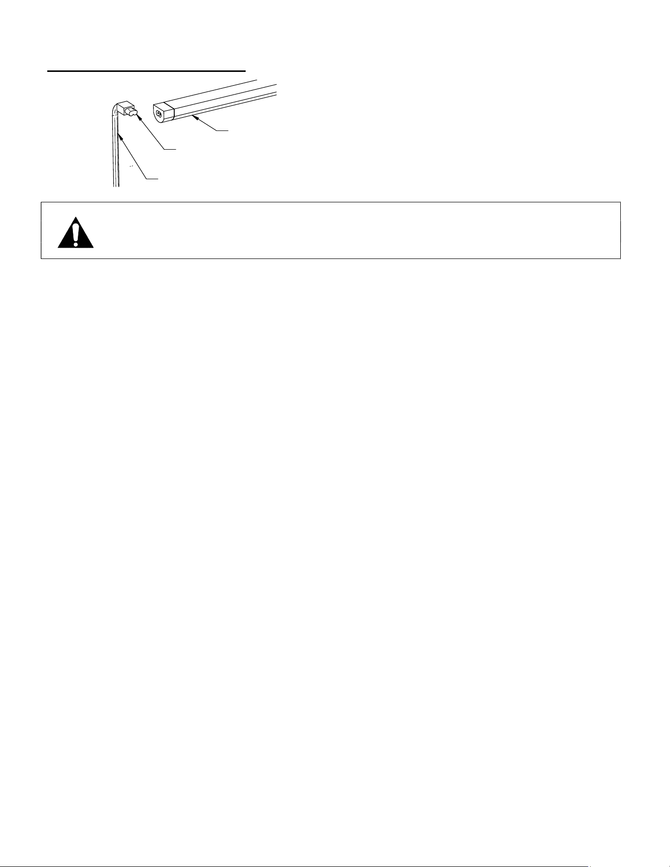
LED Light Plug Connection
LED LIGHT
LED LIGHT CORD
"B" SHAPED PLUG
NOTICE: The plug must be inserted in correct orientation into LED light.
LED light will not light if Connecting plug into LED light upside
down. It may also cause LED light failure.
Look at the end of the plug and the receptacle of LED light. On one side of the LED plug there are
two bumps and the other side there is a flat. (Similar to the letter B shape). The LED light has the
same configuration. The shapes must align correctly when inserting LED plug into the LED light.
E3788-1 Rev A - ITH 16
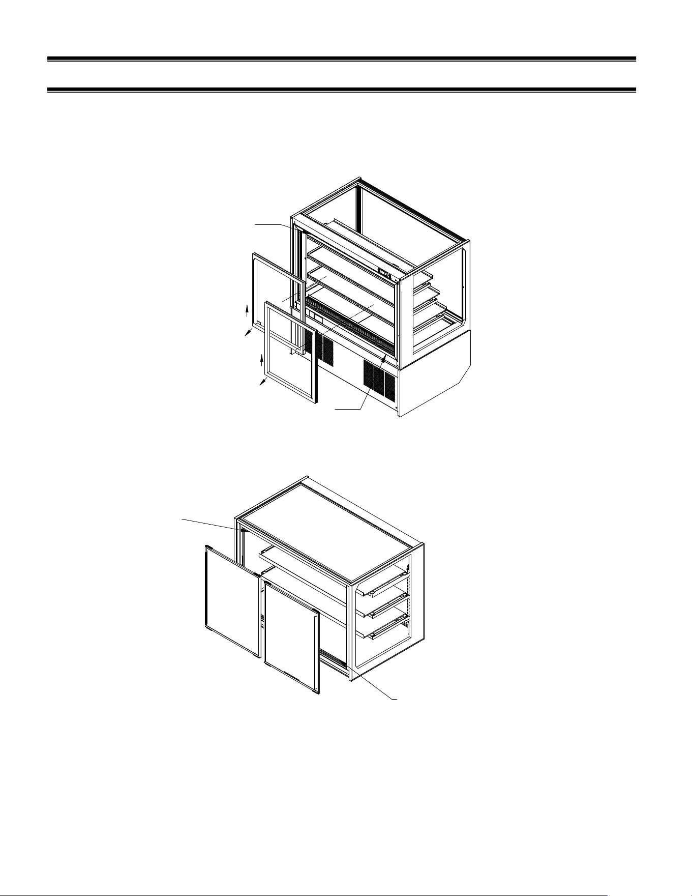
(9) FRONT AND REAR DOORS REMOVAL
UPPER TRACK
LOWER TRACK
1. LIFT UP DOOR
2. SWING BOTTOM OUT
1. LIFT UP DOOR
2. SWING BOTTOM OUT
UPPER TRACK
LOWER TRACK
1. Start with the outer door and lift the door upward until the bottom edge of door clears
the
lower track and then swing the bottom of the door outward and down out of upper
track.

E3788-1 Rev A - ITH 17
2. After the outer door is removed repeat the procedure for the inner door.
3. Reverse this procedure for door reinstallation. Rear doors are not interchangeable.
E3788-1 Rev A - ITH 18
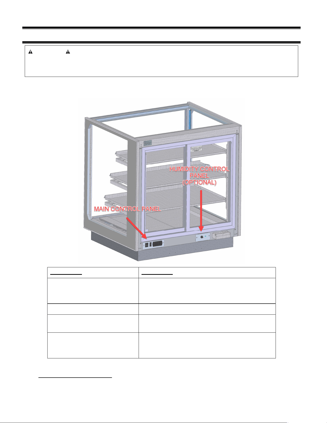
(10) CONTROL OPERATION
The controls are found on the back of the unit just below the rear door track.
CONTROL PURPOSE
POWER ON/OFF
POWER ENTIRE UNIT OFF OR ON; TURNS
OFF ALL LIGHTS, HEATERS, AND
CONTROLS
LIGHTS ON/OFF TURN ALL LIGHTS ON OR OFF
AIR TEMPERATURE
ADJUST INTERNAL CASE TEMPERATURE,
POWER ON/OFF AIR HEATING SYSTEM.
HUMIDITY (OPTIONAL)
ADJUST INTERAL HUMIDITY LEVEL OF
CASE. LIGHT ON INDICATES THAT WATER
PAN IS DRY
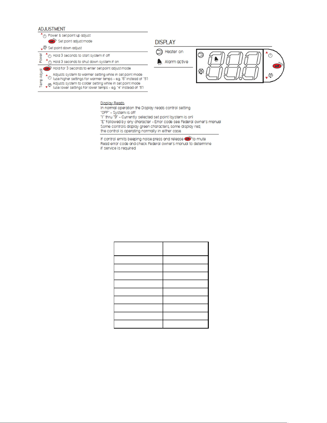
10.1 Air Temperature Control
Use the following procedure to adjust the control setpoints.
NOTICE
Load items at the intended holding temperature or greater. At time of loading, items
stocked in unit MUST be pre-heated to at least this temperature.
E3788-1 Rev A - ITH 19
Error code E0=Temperature probe disconnected or failed.
The temperature controllers each reference one temperature probe that is mounted in the deck or
shelf depending on the control. Do not locate the probe to a different position.
Temperatures are digitally controlled via factory settings 1-9. Setting “1” provides the coolest
surface temperatures while setting “9” will provide the warmest. See table below for the
temperature of each setting.
Temperature Control
Setting
Temperature [°F]
1 120
2 125
3 130
4 135
5 140
6 145
7 150
8 155
9 160
E3788-1 Rev A - ITH 20
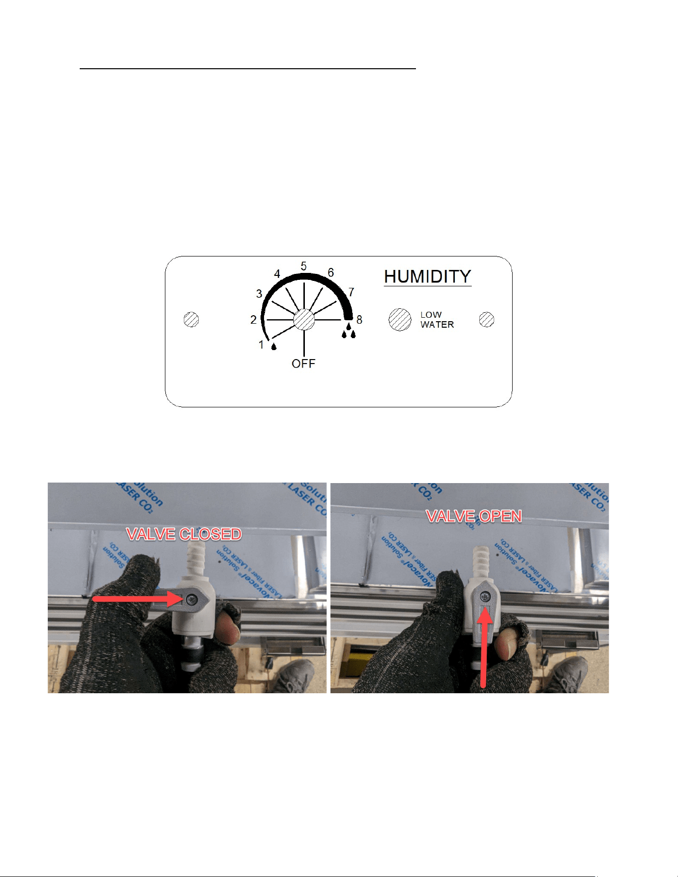
10.2 Humidity Control And Pan Operation (When Equipped)
Rotate the knob clockwise to a higher setting to increase internal cabinet humidity and
counterclockwise to reduce the humidity level.
Different air temperatures will result in different relative humidity values for the same number
setting of the control.
Turning the control to “OFF” does not prevent the addition of humidity. This setting turns off the
water pan heater that is required to increase humidity levels past what the standard air heating
element does.
To eliminate all humidity generation, simply do not add water to the pan.
See also the cleaning section of this manual for details on how to remove hard water residue.
To start using the humidity pan first check that the drain valve is in the closed position. The valve
is located on the end of the drain hose underneath the display cabinet. If equipped with a rear
panel, this panel must be removed to access the hose and valve.
Pull out the sliding cover and add water until the pan is visibly full. The amount of time the water
will last in the pan depends on the air temperature and humidity level settings chosen. At max air
and humidity settings, the water should last roughly 4hrs prior to needing refilled. When the pan
needs to be refilled the blue indicator light on the humidity control panel will light up. Water may
be added prior to this, but it is not necessary.
E3788-1 Rev A - ITH 21
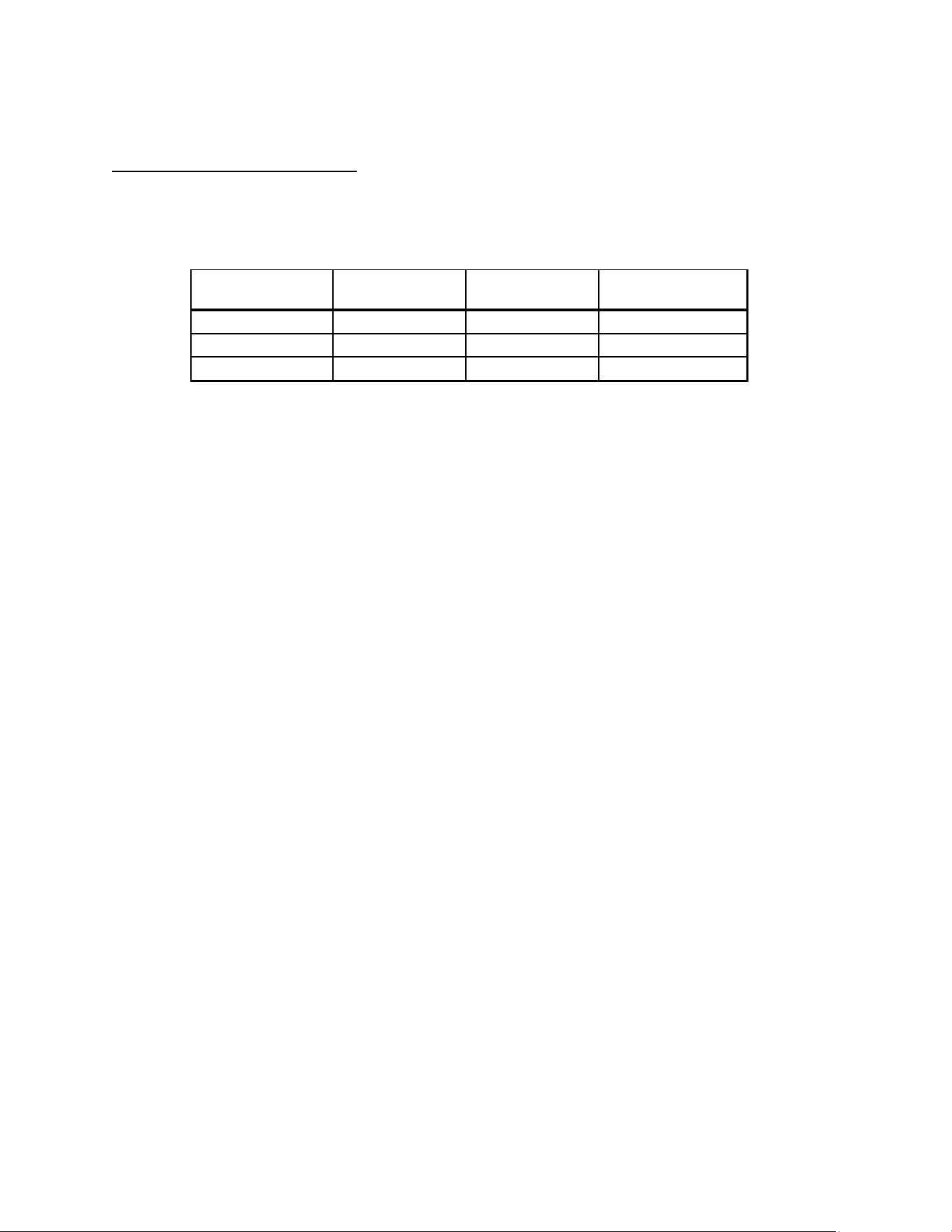
10.3 Typical Humidity Conditions
The following table represents approximate humidity levels that the humidity package can
generate at various control settings.
Temperature Control
Setting
Temperature [°F] Temperature [°C]
Relative Humidity at
max highest setting
1 120 48.9 70%
5 150 65.6 40%
9 160 71.1 20%
E3788-1 Rev A - ITH 22
(11) FOOD PACKAGING RECOMMENDATIONS
This merchandiser is designed to be used with pre-packaged product only. All food items placed
in the merchandiser must be packaged. No foods should be placed in the merchandiser without
packaging.
Not all packaging is compatible with this merchandiser. Any packaging material with a rating of
less than 200°F should not be used.
Typically, polypropylene (recycle code 5) works well, but check with the manufacturer first to get
an accurate assessment of the application.
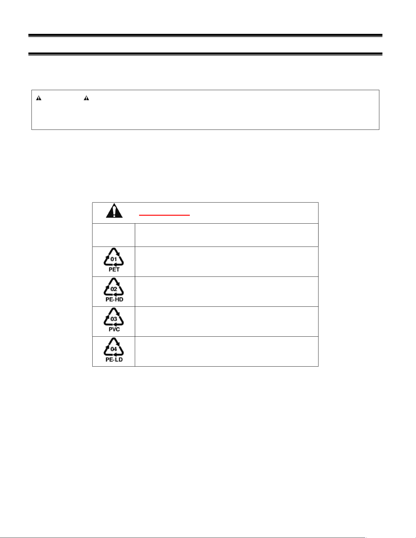
DO NOT USE the following packaging materials:
Recycle
Code Material Name
Polyethylene terephthalate
High-density polyethylene
Polyvinyl chloride
Low-density polyethylene
Materials listed in the table above will not survive the high temperature conditions of this
merchandiser.
NOTICE
Load items at the intended holding temperature or greater. At time of loading, items
stocked in unit MUST be pre-heated to at least this temperature.

E3788-1 Rev A - ITH 23
(12) INITIAL STARTUP
12.1 STARTUP
After all the checks outlined in the installation section of this manual have been made, the case is
ready to be put into service. Ensure supply power (breaker) is on and flip the Power Switch and
Light Switch on unit to the on position. Also ensure that the control is powered on as described
above.
At start up with a unit that is still cold, it is recommended that the temperature control is set to a
mid-setting, such as 5. After an hour of running, adjust the control to a warmer or a colder setting
if necessary to maintain desired product temperature. Allow heated models to run for at an hour
before placing pre-chilled product into display area.
12.1.1 Startup with the humidity package
If the unit has the optional humidity package, ensure that the fill indicator light is off. If the
indicator is on, fill the pan with water. Then turn the humidity control to the desired setting if
known. If unknown, turn the control to the highest setting. After at least an hour, adjust the control
to the desired level of humidity.
For the humidity package, internal water condensation on the glass is normal when initially
starting up the unit. If the unit has been running for more than an hour and condensation occurs
then the humidity control should be adjusted to a lower setting until the condensation goes away.
The exact setting required will vary with environmental conditions and the temperature setting of
the case.
12.2 PLACING PRODUCT INTO CASE
After completing shelving installation as outlined in “Shelving Installation and Removal” section of
this manual you may begin placing product into the display case.
Do not exceed 100 pounds of weight per shelf. Heavy product should be distributed evenly
across the entire shelving area.
Determine desired shelving location and angle before placing product in case. Product
must be removed to readjust shelf location and angle.
Do not overhang the front or sides of the shelves (or deck) with product. Product may
overhang rear of shelf, but allow a minimum of 1-1/2” between product and rear door.
Improper clearance at the sides of the shelf will block the airflow and could cause product
loss.
Do not block the slots along the sides of the display pan. Covering these slots will block
the airflow and will cause product loss.
The display pan is removable for cleaning and can become dislodged in shipment. To
ensure proper airflow and performance of the case, make sure that the display pan is
properly seated with air management slots facing the end glass. Check that the pan is
installed properly before placing product the display pans.
CASE SHOULD BE STOCKED WITH PRE-HEATED PRODUCT ONLY.
E3788-1 Rev A - ITH 24
(13) CLEANING INSTRUCTIONS
13.1 DAILY CLEANING
The case should be cleaned thoroughly, as described in the weekly cleaning section before it is
used for the first time.
NOTICE:
Avoid splashing or soaking any electrical components with water to prevent
electrical damage to the case.
NOTICE:
Shut off power switch and remove all product from case. Allow enough time
for the unit to reach room temperature before proceeding with cleaning.
NOTICE:
Remove all product from case before proceeding with cleaning procedure.
NOTICE:
This case is not designed to be cleaned by flushing.
Note: For major spills or foreign material buildup perform the weekly cleaning
instructions.
Note: Detergents are not recommended and do not use abrasive cleaners or pads to
prevent scratching of surfaces.
1. Clean all foreign materials from the door opening.
1. Wipe complete interior of both the upper & lower areas of case using a damp cloth.
2. The remaining exterior surface should be wiped down using any ammoniated cleaners or soapy
warm water.
13.2 WEEKLY CLEANING
This procedure is recommended on a weekly basis. It may need to be performed more often if
necessary, to maintain a clean, sanitary case. The case should be cleaned to this procedure before
using the first time.
NOTICE:
Avoid splashing or soaking any electrical components with water to prevent
electrical damage to the case.
E3788-1 Rev A - ITH 25
NOTICE:
Shut off power switches and remove all product from case. Allow enough
time for the unit to reach room temperature before proceeding with cleaning.
NOTICE:
Remove all product from case before proceeding with cleaning procedure.
NOTICE:
This case is not designed to be cleaned by flushing.
1. Side, and rear door glass can be cleaned with common window cleaners.
2. Remove interior shelving and display deck from unit as described in the “Shelving Installation and
Removal” section of this manual.
3. Clean all shelves, shelf supports, shelf light deflectors, shelf brackets, shelf standards using warm
soapy water and a brush. Rinse thoroughly and allow to dry.
4. Remove the display deck and clean using warm soapy water and a brush. Rinse thoroughly and
allow to dry.
5. Clean the entire interior of the case using warm soapy water. Wipe off all soapy water with a
damp cloth and allow to dry. (DO NOT use solvents such as Acetone, Benzene, Carbon
Tetrachloride, and Lacquer Thinners)
6. Reassemble all components in reverse order.
7. The exterior surfaces should be wiped down using any ammoniated cleansers or warm soapy
water.
13.3 CLEANING THE OPTIONAL HUMIDITY PAN
The humidity pan will need to be cleaned on a regular basis. The frequency of the cleaning
required is directly related to the hardness of water being added to the pan. See table below.
gpg = grains per gallon
To clean the humidity pan:
1. Locate the drain hose protruding from underneath the case. The rear panel will need to be
removed if included.
2. Using a 2.5gal bucket or other container, open the drain valve and let the water drain completely
into the bucket.
Water
Hardness
Cleaning Interval
Recommendation
0 gpg Typically not required
1-9 gpg Once per month
10-20 gpg Twice per month
20+ gpg Weekly

E3788-1 Rev A - ITH 26
3. Close the drain valve to prevent any further flow.
4. Add a 50% white vinegar (5% acidity) 50% water solution to the pan until it is full.
5. Turn the humidity up to the highest setting.
6. Allow the unit to run for 30mins to dissolve the scale buildup in the pan.
7. Drain the solution into a bucket and discard using the same method described for remaining water
above.
8. For extreme scale buildup this procedure may need to be repeated, or full strength vinegar may be
required.
Other lime scale removal products may be used for this process, but anything used should be
food safe.

E3788-1 Rev A - ITH 27
(14) SERVICE
Service Information
Before any service work is
performed on the case, make
sure all power is disconnected to
the case.
To find a service company in your area, please visit our website at
https://federalind.com/support-service/service-rep-locator. There you can also find self-
service tools to help you get the answers you need faster!
For warranty service requests and all technical support, including compressors and other
service parts please contact:
- Phone: (833) 238-8168
- Email: techservice@partstown.com
Federal Industries has partnered with Parts Town for ALL Non-Warranty Part Identification,
Pricing, Lead Times, Orders & Freight Quotes. Please contact Parts Town directly if you
need parts:
- Website: PartsTown.com
- Phone: 833-809-8188
WARNING
RISK OF ELECTRIC
SHOCK
DISCONNECT POWER
BEFORE SERVICING UNIT

E3788-1 Rev A - ITH 28
(15) SALE & DISPOSAL
15.1 OWNER RESPONSIBILITY
If you sell or give away your Federal Industries case you must make sure that all safety labels
and the Installation-Service Manual are included with it. If you need replacement labels or
manuals, Federal Industries will provide them free of charge. Contact the customer service
department at Federal Industries at (800) 356-4206.
The customer service department at Federal Industries should be contacted at the time of sale or
disposal of your case so records may be kept of its new location.

E3788-1 Rev A - ITH 29
(16) TROUBLESHOOTING
Pre-Service Checklist
You may avoid the cost and inconvenience of an unnecessary service call by first
reviewing this checklist of frequently encountered situations that can cause unsatisfactory
case performance.
Case Does Not Operate
Check for disconnected power supply.
Check for tripped breaker on blown fuse.
Check that the thermostat display is on and is not displaying an error.
Lights Do Not Operate
Check that light switch is on.
Check for tripped breaker or blown fuse.
Check that light cords are plugged in correctly to sockets. Check connector on LED
light, and connector on
Temperature is too low
Increase control setpoint
Check supply voltage to case is above 208V
Look for HVAC discharge vents, fans, and other possible air disruptions.
Temperature is too high
Turn down control setpoint
Check the control for errors and contact service
Control Error
Turn the main power switch to off to power down the unit
Wait 10s, and power the unit back on
E3788-1 Rev A - ITH 30
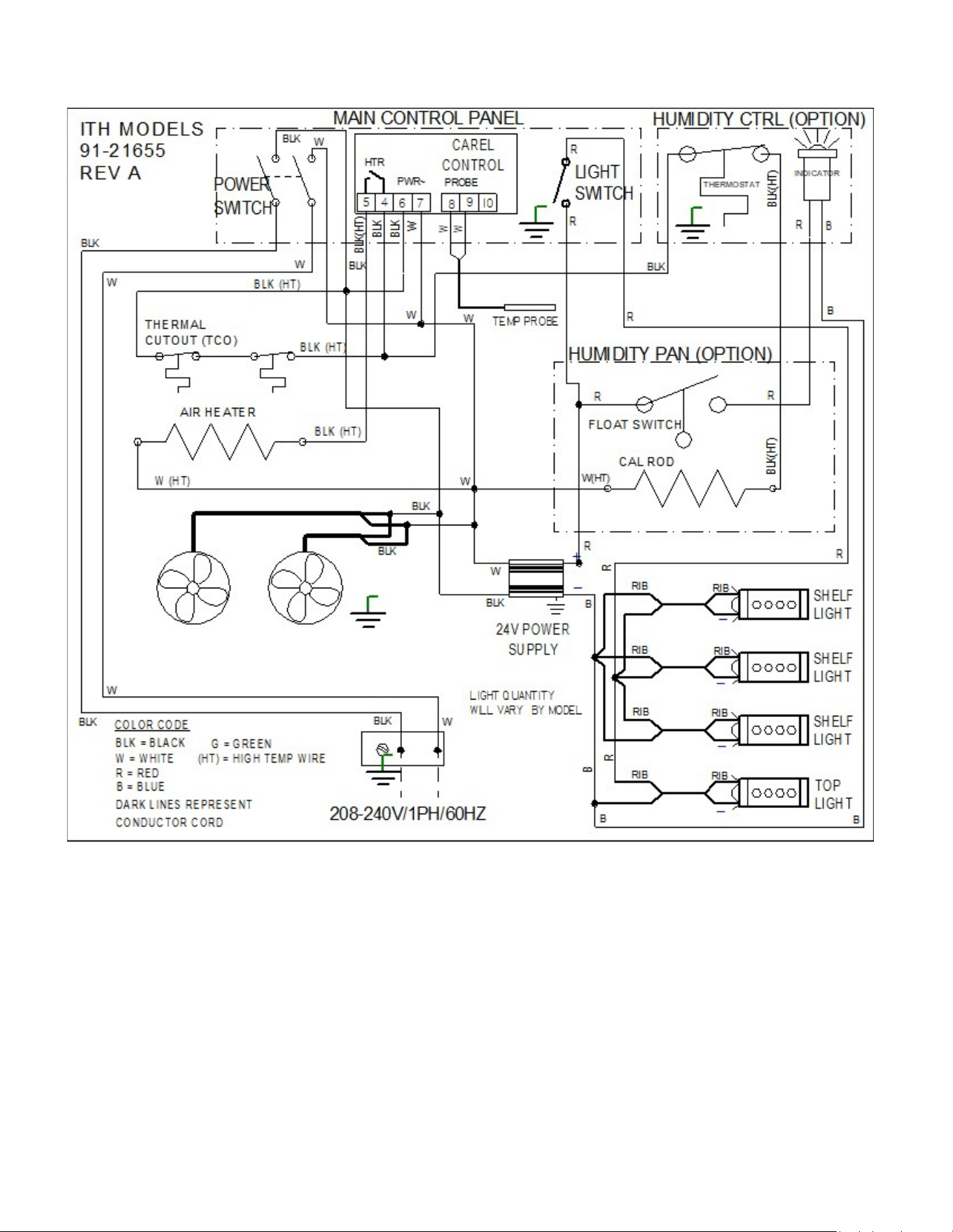
Wiring Diagrams
E3788-1 Rev A - ITH 31
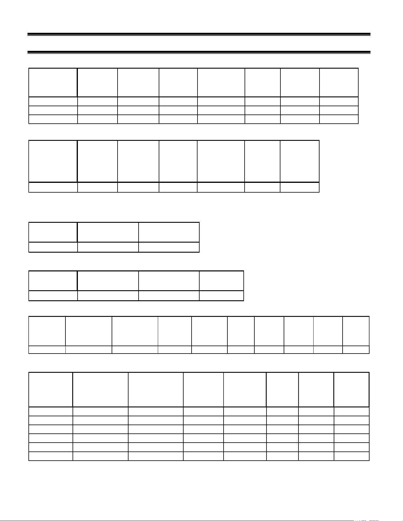
(17) SERVICE PARTS
ELECTICAL COMPONENTS
MODELS LIGHT SWITCH POWER
SWITCH
LIGHT 24V LED
STRIP
SHELF
LIGHT
CORD
ITH36
41-11066 41-18186 39-20555 42-20870-29C35 43-20475 91-21655 43-21641
ITH48
41-11066 41-18186 39-20555 42-20870-40C35 43-20475 91-21655 43-21641
ITH60
41-11066 41-18186 39-20555 42-20870-51C35 43-20475 91-21655 43-21641
MAIN WIRE
HARNESS
LIGHT POWER
SUPPLY
MAIN WIRING
DIAGRAM
AIR HEATING COMPONENTS
MODELS
AIR HEATER FAN
FAN CORD
ELECTRONIC
CONTROL
TEMPERATURE
PROBE
THERMAL
OVERLOAD
PROTECTOR
ALL
40-21532 41-21617 43-11171 32-19865-20 32-21046 41-17129
HUMIDITY PACKAGE COMPONENTS
MODELS
CONTROL ASSEMBLY PAN ASSEMBLY
ALL
SA6124-2 SA6122
HUMIDITY PACKAGE CONTROL COMPONENTS
MODELS
CONTROL INDICATOR LIGHT
DECAL
ALL
41-21646 42-21629 91-21649
HUMIDITY PAN COMPONENTS
MODELS
PAN PAN LID HEATER
DRAIN TUBE
DRAIN VALVE
HOSE
CLAMPS
FLOAT
SWITCH
THERMOSTAT
PROBE
BRACKET
ENCLOSURE
GASKET
ALL
SA6121 M21860 40-21598-3 15-21606 84-21608 81-21609 41-21621 M21832 16-12426
GLASS COMPONENTS
MODELS FRONT GLASS /
PLASTIC ON SS
TOP GLASS END GLASS
CLEAR. L.H. SS
TRIM.
W/SCREWS
END GLASS
CLEAR. R.H. SS
TRIM
W/SCREWS
END GLASS
REFL. L.H.
SS TRIM
W/SCREWS
END GLASS
REFL. R.H.
SS TRIM
W/SCREWS
FRONT GLASS
MAGNET SIDE
ITH3626
51-20598-4 51-20599-4 SA6138-1L SA6138-1R SA6138-3L SA6138-3R 64-20476-5
ITH4826
51-20598-5 51-20599-4 SA6138-1L SA6138-1R SA6138-3L SA6138-3R 64-20476-5
ITH6026
51-20598-6 51-20599-4 SA6138-1L SA6138-1R SA6138-3L SA6138-3R 64-20476-5
ITH3634
51-20598-1 51-20599-1 SA6138-L SA6138-R SA6138-2L SA6138-2R 64-20476-4
ITH4834
51-20598-2 51-20599-2 SA6138-L SA6138-R SA6138-2L SA6138-2R 64-20476-4
ITH6034
51-20598-3 51-20599-3 SA6138-L SA6138-R SA6138-2L SA6138-2R 64-20476-4
E3788-1 Rev A - ITH 32
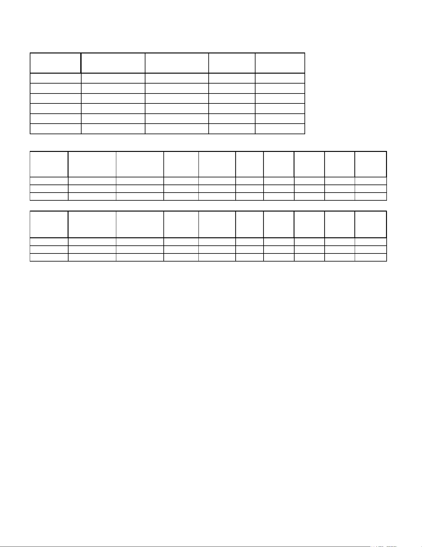
REAR DOORS
MODELS
DOOR LEFT CLEAR DOOR RIGHT CLEAR DOOR LEFT
REFLECTIVE
DOOR RIGHT
REFLECTIVE
ITH3626
53-20467-4 53-20468-4 53-20467-4A 53-20468-4A
ITH4826
53-20467-5 53-20468-5 53-20467-5A 53-20468-5A
ITH6026
53-20467-6 53-20468-6 53-20467-6A 53-20468-6A
ITH3634
53-20467-1 53-20468-1 53-20467-1A 53-20468-1A
ITH4834
53-20467-2 53-20468-2 53-20467-2A 53-20468-2A
ITH6034
53-20467-3 53-20468-3 53-20467-3A 53-20468-3A
SHELF & DECK COMPONENTS (BEFORE 5/1/25)
MODELS
S/S SHELF - 11"
(NOT STANDARD FOR 26IN
MODELS)
S/S SHELF - 14" S/S SHELF - 17" SHELF BRACKET
FOR 11" SHELF
SHELF
BRACKET
FOR 14"
SHELF
SHELF
BRACKET
FOR 17" SHELF
DISCHARGE
DISPLAY DECK
(LEFT)
INTAKE DISPLAY
DECK (RIGHT -
TEMP CONTROL
SIDE)
SHELF
STANDARD
ITH36
M21813-1 M21813-2 M21813-3 67-20621-1L 67-20621-2L 67-20621-3L SA6126-1 SA6120-1 M20442
ITH48
M21813-4 M21813-5 M21813-6 67-20621-1L 67-20621-2L 67-20621-3L SA6126-2 SA6120-2 M20442
ITH60
M21813-7 M21813-8 M21813-9 67-20621-1L 67-20621-2L 67-20621-3L SA6126-3 SA6120-3 M20442
SHELF & DECK COMPONENTS (AFTER 5/1/25)
MODELS
S/S SHELF - 11"
(NOT STANDARD FOR 26IN
MODELS)
S/S SHELF - 14" S/S SHELF - 17" SHELF BRACKET
FOR 11" SHELF
SHELF
BRACKET
FOR 14"
SHELF
SHELF
BRACKET
FOR 17" SHELF
DISCHARGE
DISPLAY DECK
(LEFT)
INTAKE DISPLAY
DECK (RIGHT -
TEMP CONTROL
SIDE)
SHELF
STANDARD
ITH36
M21813-1 M21813-2 M21813-3 67-21865-1L 67-21865-2L 67-21865-3L SA6126-1 SA6120-1 M22240
ITH48
M21813-4 M21813-5 M21813-6 67-21865-1L 67-21865-2L 67-21865-3L SA6126-2 SA6120-2 M22240
ITH60
M21813-7 M21813-8 M21813-9 67-21865-1L 67-21865-2L 67-21865-3L SA6126-3 SA6120-3 M22240

E3788-1 Rev A - ITH 33
REV
CHANGE RECORD
APP’D DATE ECN#
- INITIAL RELEASE JTR 3/3/2023 3856
A Added service parts, humidity details, and initial startup section. JTR 5/17/2023 -
B Updated service parts, wiring diagram, and control cutouts. JTR 11/6/2023 3864
C NEW SHELF BRACKET AND STANDARDS SES 3/3/25 3945
California Residents Only.
WARNING
This product can expose you to chemicals including chromium which is known to the State of California to
cause cancer and birth defects or other reproductive harm. For more information go to
www.P65Warnings.ca.gov