PDF export of the original HTML manual
Spectera
Bidirectional, wireless broadband ecosystem
Spectera v1.4.2 | 09/2026

Contents
1. Preface............................................................................................................................................ 6
2. Quick start......................................................................................................................................7
3. Product information......................................................................................................................9
Spectera System........................................................................................................................9
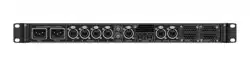
Base Station..............................................................................................................................10
WebUI.........................................................................................................................................12
SEK............................................................................................................................................. 13
SKM............................................................................................................................................ 14
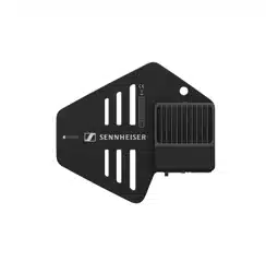
DAD............................................................................................................................................ 15
Accessories............................................................................................................................... 16
Accessories for the Base Station...................................................................................16
Accessories for the SEK..................................................................................................18
Accessories for the SKM................................................................................................ 20
Accessories for the DAD................................................................................................. 21
CHG 70N-C network-enabled charger.......................................................................... 22
BA 70 rechargeable battery and L 70 USB charger.................................................... 24
Modular L 6000 charger................................................................................................. 25
Charging modules for L 6000 charger..........................................................................27
4. Instruction manual .................................................................................................................... 30
Base Station............................................................................................................................. 30
Get started........................................................................................................................30
General information for the System..............................................................................34
Product overview............................................................................................................. 35
Installing slot-in cards..................................................................................................... 37
Connecting/disconnecting the Base Station to/from the power supply
system............................................................................................................................... 40
Connecting to a network................................................................................................ 42
Connecting antennas.......................................................................................................44
Connecting word clock................................................................................................... 46
Connecting audio via Dante®......................................................................................... 49
Connecting audio via MADI............................................................................................ 51
Changing the fan filter.................................................................................................... 52
Installing the Base Station in a rack............................................................................. 54
Switching the Base Station on and into standby........................................................ 56
Activating a license (general)......................................................................................... 57

Using the headphone output..........................................................................................59
Meaning of the LED.........................................................................................................60
Information on the display.............................................................................................. 61
Navigating the menu....................................................................................................... 62
Menu structure.................................................................................................................63
Updating the Base Station..............................................................................................74
WebUI........................................................................................................................................ 75
Getting started................................................................................................................. 75
Configuration.................................................................................................................... 94
Frequency Scan...............................................................................................................157
Audio Metering................................................................................................................ 161
Audio inputs and outputs..............................................................................................162
Changing the device password.................................................................................... 163
SEK........................................................................................................................................... 165
Product overview............................................................................................................165
Inserting and removing the rechargeable battery......................................................167
Mounting the antenna....................................................................................................170
Using the protection cap................................................................................................171
Connecting a microphone / instrument...................................................................... 172
To use the Phones jack..................................................................................................175
Connecting the COM Button......................................................................................... 177
Changing the belt clip....................................................................................................178
Meaning of the LEDs...................................................................................................... 181
Switching the SEK on and off...................................................................................... 184
Information on the display............................................................................................ 186
Pairing the SEK to the Base Station............................................................................190
Operating the SEK with the COM Button.................................................................... 191
Updating the SEK........................................................................................................... 192
SKM.......................................................................................................................................... 193
Product overview............................................................................................................193
Inserting and removing the rechargeable battery..................................................... 194
Replace microphone module........................................................................................ 195
Attaching the SKM COM............................................................................................... 197
Meaning of the LED....................................................................................................... 199
Switching the SKM on and off......................................................................................201
Information on the display........................................................................................... 203
Pairing the SKM to the Base Station.......................................................................... 205

Using the SKM COM..................................................................................................... 206
Updating the SKM..........................................................................................................207
DAD..........................................................................................................................................208
Product overview........................................................................................................... 208
Information on antenna setup......................................................................................209
Meaning of the LED........................................................................................................ 211
Placing on a stand..........................................................................................................212
Connecting/disconnecting the antenna......................................................................214
Antenna cable extension............................................................................................... 217
Updating the DAD.......................................................................................................... 218
CHG 70N-C charger...............................................................................................................219
Product overview............................................................................................................ 219
Connecting/disconnecting the charger to/from the power supply system........... 221
Connecting a charger in a network.............................................................................223
Cascading chargers.......................................................................................................224
Charging the rechargeable battery............................................................................. 226
Power saving mode....................................................................................................... 228
Updating the firmware of the charger........................................................................ 229
L 70 USB charger.................................................................................................................. 232
Connecting/disconnecting the charger to/from the power supply system...........232
Charging the rechargeable battery............................................................................. 233
Modular L 6000 charger...................................................................................................... 235
Product overview........................................................................................................... 235
Connecting/disconnecting the L 6000 to/from the power supply system............236
Connecting the L 6000 to a network.......................................................................... 237
Installing a charging module in the L 6000 charger.................................................239
Installing the L 6000 in a rack..................................................................................... 241
Switching the L 6000 on and off.................................................................................243
Charging the rechargeable batteries in the L 6000 charger................................... 244
Meaning of the LEDs.....................................................................................................246
Preparing rechargeable batteries for storage (storage mode).................................248
Resetting settings (factory reset)................................................................................249
Updating the firmware.................................................................................................. 250
Operating the L 6000 via a network............................................................................251
Cleaning and maintenance...................................................................................................252
5. Knowledge base........................................................................................................................253
Troubleshooting..................................................................................................................... 253

License activation fails................................................................................................. 253
No device access via the WebUI.................................................................................256
The Base Station cannot be found.............................................................................. 257
Interference noise with old RF devices...................................................................... 258
Noise in the audio signal.............................................................................................. 259
6. Specifications............................................................................................................................260
Spectera System................................................................................................................... 260
Base Station........................................................................................................................... 262
WebUI......................................................................................................................................265
SEK.......................................................................................................................................... 266
SKM......................................................................................................................................... 268
SKM COM............................................................................................................................... 269
DAD..........................................................................................................................................270
CHG 70N-C charger.............................................................................................................. 272
BA 70 rechargeable battery................................................................................................. 274
L 70 USB charger...................................................................................................................275
Modular L 6000 charger.......................................................................................................276
LM 6060 | LM 6061 | LM 6062 | LM 6070 charging modules.......................................... 278

Spectera
1. Preface
PDF Export of the Original HTML Manual
This PDF document is an automatic export of an interactive set of HTML manuals. Some
content and interactive elements may not be included in the PDF because they cannot
be displayed in this format. In addition, automatically generated page breaks may cause
related content to be slightly shifted. We can therefore only guarantee the completeness
of the information in the HTML manual and recommend using it. You can find it in the
Documentation Portal at www.sennheiser.com/documentation.
6
Spectera
2. Quick start
All necessary information for activating the license and configuring the required ports of
the device.
When starting up the Base Station for the first time, it is necessary to have a direct internet
connection to activate the license. Additionally, certain ports must be enabled (especially for
the organization/enterprise firewall) for communication between software and devices.
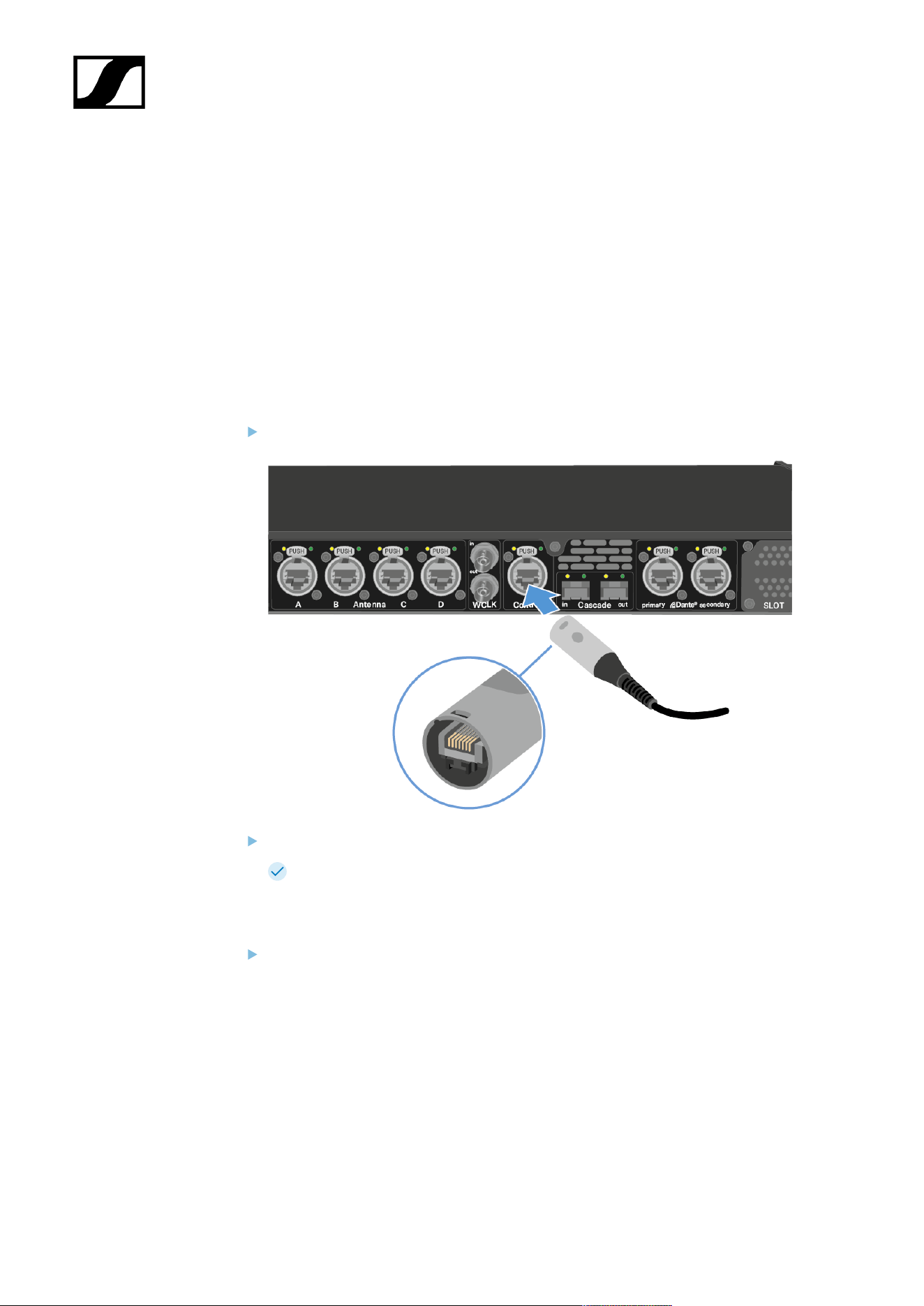
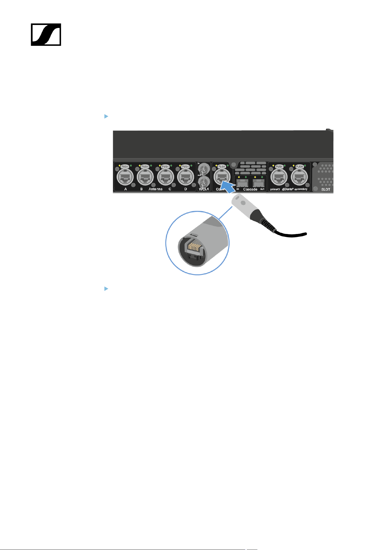
1. Connect the Base Station to a network:
Plug one side of the network cable into the Control socket.
Plug the other side of the network cable to a switch or router.
The Base Station has been connected to a network.
2. Enable necessary ports for activation:
Please contact your IT administrator to provide Internet access to the License Server
and any NTP server by opening the required network ports and to provide DNS
settings via DHCP to the device.
Address Port Protocol Type Service Usage
my.nalpeiron.com 80 HTTPS
(TCP)
Unicast Sennheiser
License Server
Activation of
devices
7
| 2 - Quick start
ANY (see list of NTP
servers)
123 NTP Unicast NTP Time
Server
Synchronize
system time
You can find the complete overview of all ports at Ports, protocols and
services.
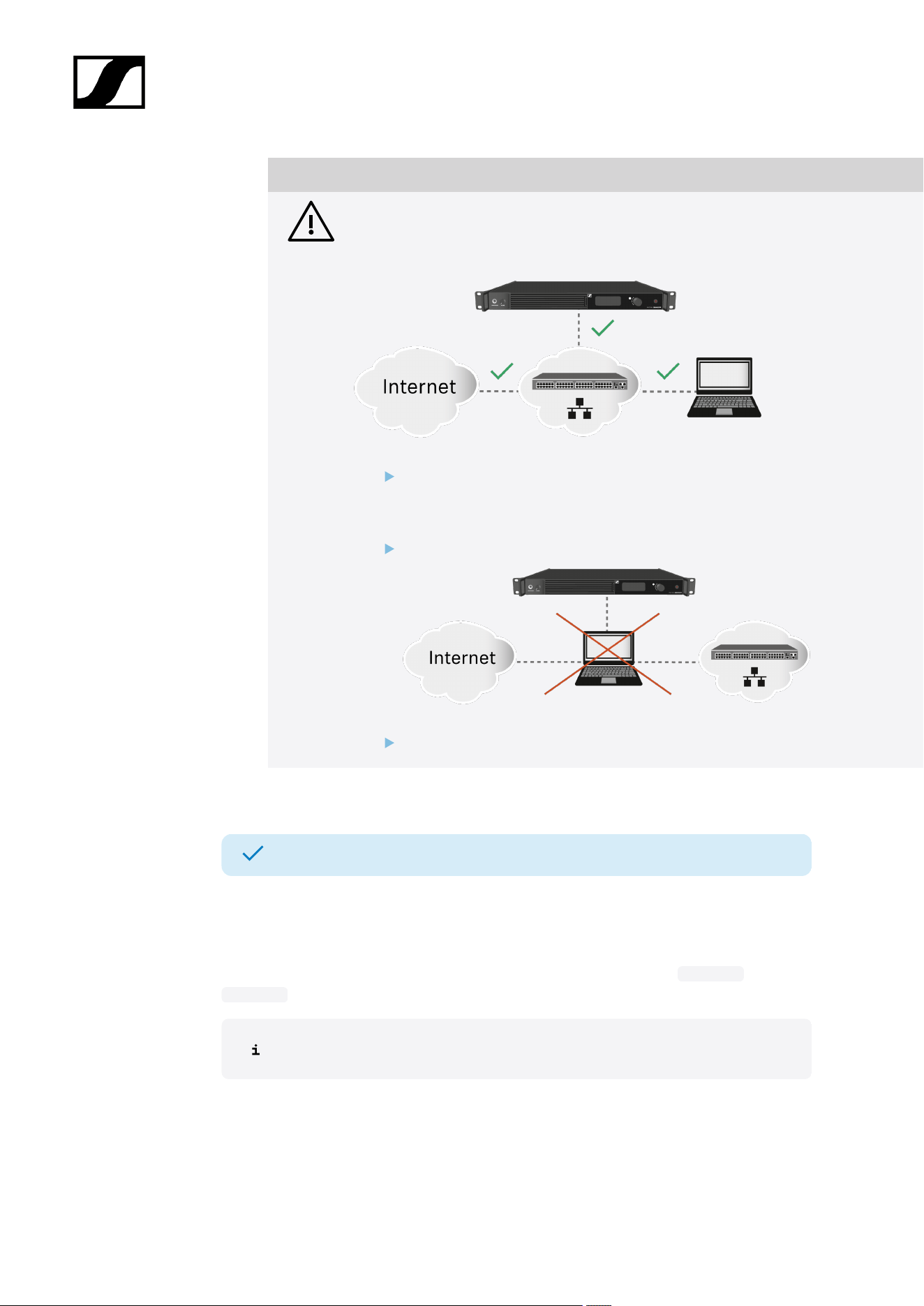
3. Ensure that the network has an Internet connection and activate the license:
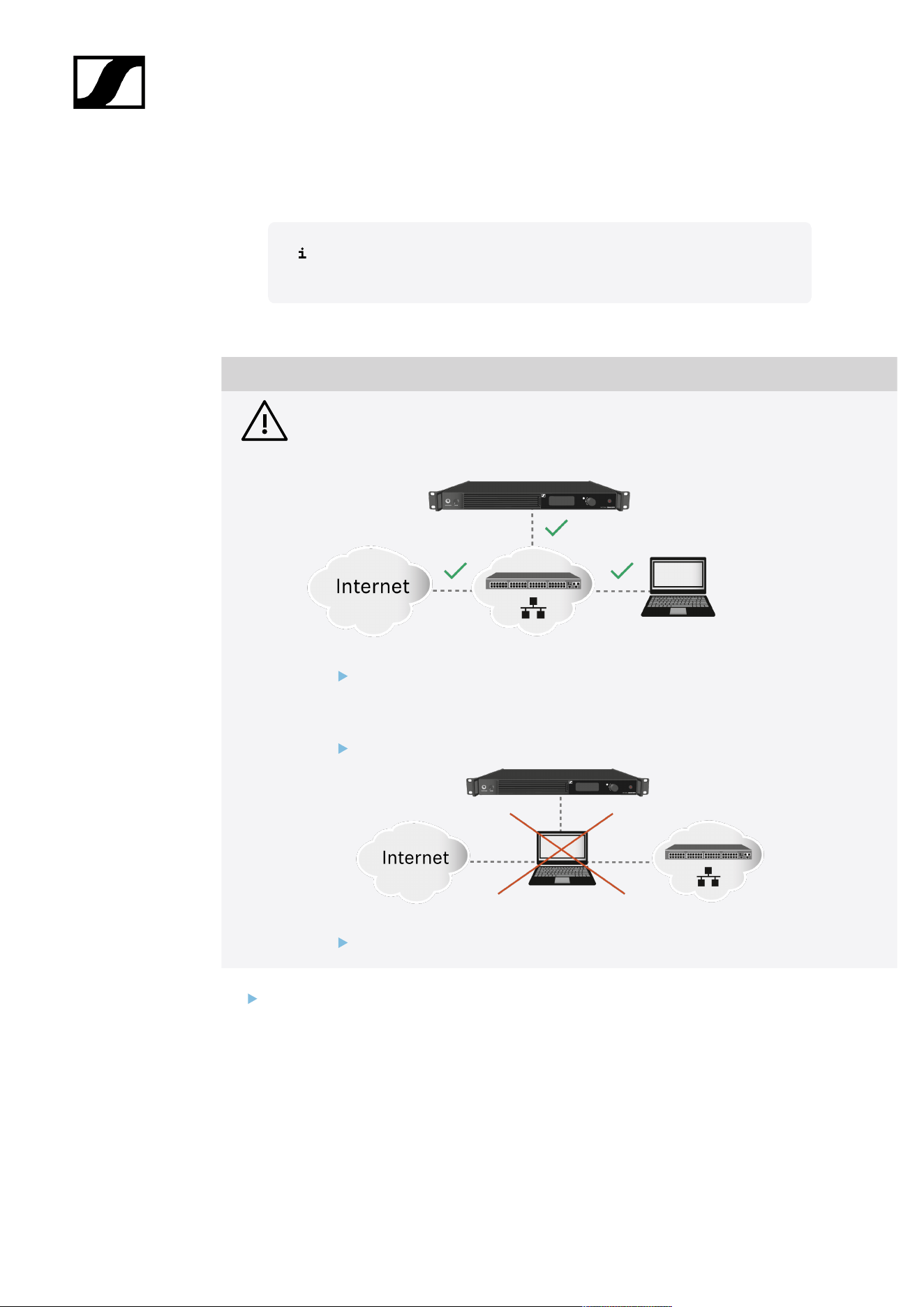
NOTICE
License activation requires a direct Internet connection to the device
In order to activate the Base Station using the 18-digit license code, a direct Internet
connection is required.
Please connect your Base Station directly to a network with Internet access via
a switch or router. For more information, refer to the chapter Connecting to a
network.
Direct connections via laptop etc. are not supported for activation!
The Internet is only required once for activation.
If you want to activate a license via Spectera WebUI, follow the steps described here:
Activating a license (WebUI).
8

Spectera
3. Product information
All information about the product, the scope of delivery and the available accessories.
Spectera System
Sensing Capabilities - Audio detection and transmission
Spectera devices (Base Station, DAD, SEK) build audio transmission system for professional
use. Once paired, SEK mobile devices can transmit audio signals captured by a connected
microphone over radio frequencies. Due to its bi-directionality, the SEK is able to receive
audio signals from DAD and the sound comes out of the headphones, if any connected. Here
how it works:
Transmission:
1. The microphone connected to the SEK picks up the sound and converts it into
electrical signals.
2. The SEK then prepares these signals for transmission by amplifying and modifying
them.
3. The signals are sent over radio waves to the DAD Antenna.
4. The DAD antenna changes the radio back into electrical signals and sent them to the
Base Station for further audio processing.
Receiving:
1. The Base Station forward audio signals to the DAD Antenna.
2. These signals are then prepared for transmission by boosting and modifying them.
3. The signals are sent over radio waves to the SEK mobile devices.
4. The SEK changes the radio back into electrical signals and at a further stage, sound
will be directed to connected headphones.
9
| 3 - Product information
Base Station
Base Station | 1350 - 1525 MHz | Art. no. 509162
The license for the Base Station is available in the following versions:
Name Art.
no.
Frequency range Certified Countries*
SPECTERA LIC
(ZONE 01)
700
532
UHF (470 - 608 MHz, 630 - 698 MHz)
1G4 (1350 - 1400 MHz, 1492 - 1525
MHz)
EU + EFTA, United
Kingdom, Turkey
SPECTERA LIC
(ZONE 02)
700
533
UHF (470 - 608 MHz, 657 - 663 MHz)
1G4 (1435 - 1525 MHz Certification
pending)
USA
SPECTERA LIC
(ZONE 03)
700
534
UHF (470 - 608 MHz, 657 - 663 MHz) Canada
SPECTERA LIC
(ZONE 04)
700
535
UHF (470 - 534 MHz, 534 - 608 MHz,
630 - 698 MHz)
Singapore
SPECTERA LIC
(ZONE 05)
700
536
UHF (470 - 608 MHz, 630 - 698 MHz)
1G4 (1350 - 1400 MHz)
South Africa
SPECTERA LIC
(ZONE 06)
700
537
UHF (470 - 608 MHz, 630 - 694 MHz) Malaysia, Qatar
SPECTERA LIC
(ZONE 07)
700
538
UHF (470 - 510 MHz, 630 - 698 MHz) Israel
SPECTERA LIC
(ZONE 08)
700
539
UHF (487 - 608 MHz, 630 - 694 MHz) Indonesia
SPECTERA LIC
(ZONE 09)
700
540
UHF (470 - 608 MHz, 630 - 694 MHz)
1G4 (1350 - 1400 MHz)
United Arab Emirates
SPECTERA LIC
(ZONE 10)
700
541
UHF (470 - 608 MHz, 630 - 698 MHz) Philippines
SPECTERA LIC
(ZONE 11)
700
542
UHF (520 - 608 MHz, 630 - 694 MHz) Australia
SPECTERA LIC
(ZONE 12)
700
543
UHF (510 - 606 MHz) New Zealand
10
| 3 - Product information
Name Art.
no.
Frequency range Certified Countries*
SPECTERA LIC
(ZONE 13)
700
544
UHF (479 - 565 MHz) Hong Kong
SPECTERA LIC
(ZONE 14)
700
728
UHF (470 - 608 MHz) Egypt, Mexico
SPECTERA LIC
(ZONE 15)
701
015
UHF (510 - 530 MHz, 630 - 698 MHz, 6
MHz Bandwidth)
Taiwan
SPECTERA LIC
(ZONE 16)
701
016
UHF (470 - 608 MHz, 6 MHz
Bandwidth)
Brazil
SPECTERA LIC
(ZONE 17)
701
016
UHF (470 - 510 MHz, 630 - 698 MHz) China
* It is the responsibility of the user to inform themselves about the current local regulatory
and certification requirements and to comply with them using wireless systems.
You can find more detailed information about the Base Station in the following
sections:
• Startup and operation: Base Station
• Specifications: Base Station
11
| 3 - Product information
WebUI
Information about supported devices, design, functionality and the main features of the
software at a glance.
Spectera WebUI is a self-hosted, browser-based and user-friendly interface for the dedicated
control and monitoring of Spectera devices.
The WebUI offers you an intuitive Configuration with essential remote control and
monitoring functions, such as IEM volume, latency, audio level and settings, RF status,
battery status and much more. The Frequency Scan provides a continuous spectrum
scan via Spectera's innovative DAD antenna. Plus, the Audio Levels view shows all inputs
and outputs of the connected interfaces on one page. All audio channels and links are
summarized in the Audio IO view and can be easily adjusted.
Key Features
• Self-hosted, browser-based and user-friendly interface for the dedicated control and
monitoring of Spectera devices.
• Online interface for full system management.
• A tool-tip provides contextual additional information that appears when hovering over
an element with the mouse.
• Complete remote control and monitoring of all Spectera ecosystem components,
including the Base Station, DAD antenna, and SEK bodypacks, all on a single page.
• Unprecedented remote control and monitoring capabilities, plus visibility of:
• Interference Level (IF)
• Receive Signal Strength Indication (RSSI)
• Link Quality Input (LQI)
• IEM settings (Interface, CH, Mode, Balance, Volume)
• MIC settings (Mic/Line, Cable Emulation, Low Cut, Preamp Gain, Test Tone,
Mode, CH)
• Continuous spectrum scanning via DAD antenna available.
• Regional license key for activating the Base Station.
You can find more detailed information about the WebUI in the following sections:
• Instruction manual: WebUI
• Specifications: WebUI
12
| 3 - Product information
DAD
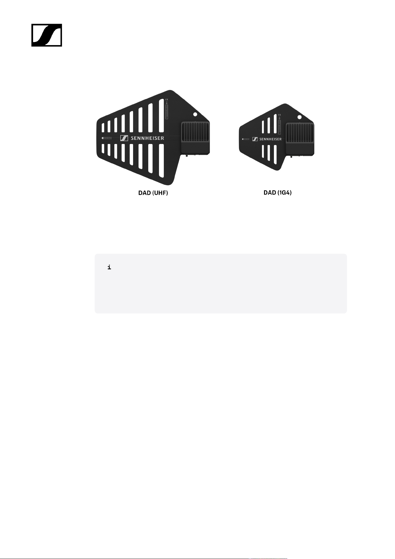
The Digital Antenna Directional (DAD) is available in the following versions:
DAD UHF | 470 - 698 MHz | Art. no. 509169
DAD 1G4 | 1350 - 1525 MHz | Art. no. 509170
You can find more detailed information about the DAD in the following sections:
• Startup and operation: DAD
• Specifications: DAD
15
| 3 - Product information
Accessories for the SEK
Spectera SEK Antenna
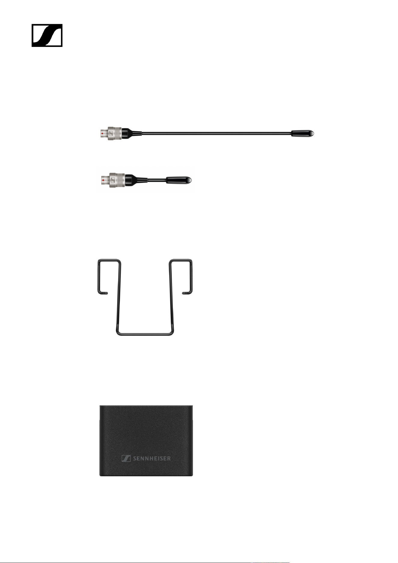
SEK Antenna (UHF) | 470 - 698 MHz | Art. no. 700066
SEK Antenna (1G4) | 1350 - 1525 MHz | Art. no. 700067
• See Mounting the antenna
Spectera SEK Belt Clip
SEK Belt Clip | Art. no. 700071
• See Changing the belt clip
Spectera SEK Battery Cover
Exchangeable battery cover | Art. no. 700556
18
| 3 - Product information
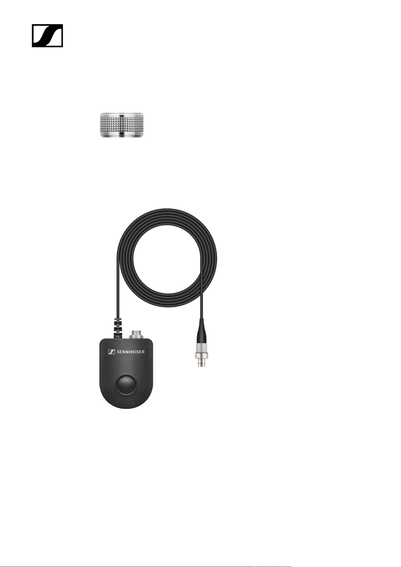
3-pin protective cap MIC/LINE
Exchangeable protective cap for the microphone / instrument 3-pin connector | Art. no.
700072
• See Using the protection cap
COM Button
Command adapter for SEK | Art. no. 701014
• See Connecting the COM Button
• See Operating the SEK with the COM Button
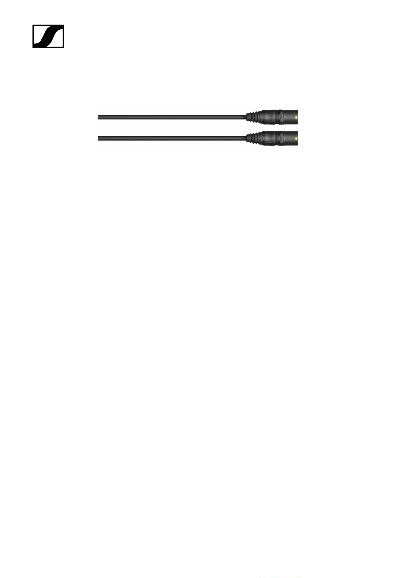
19
| 3 - Product information
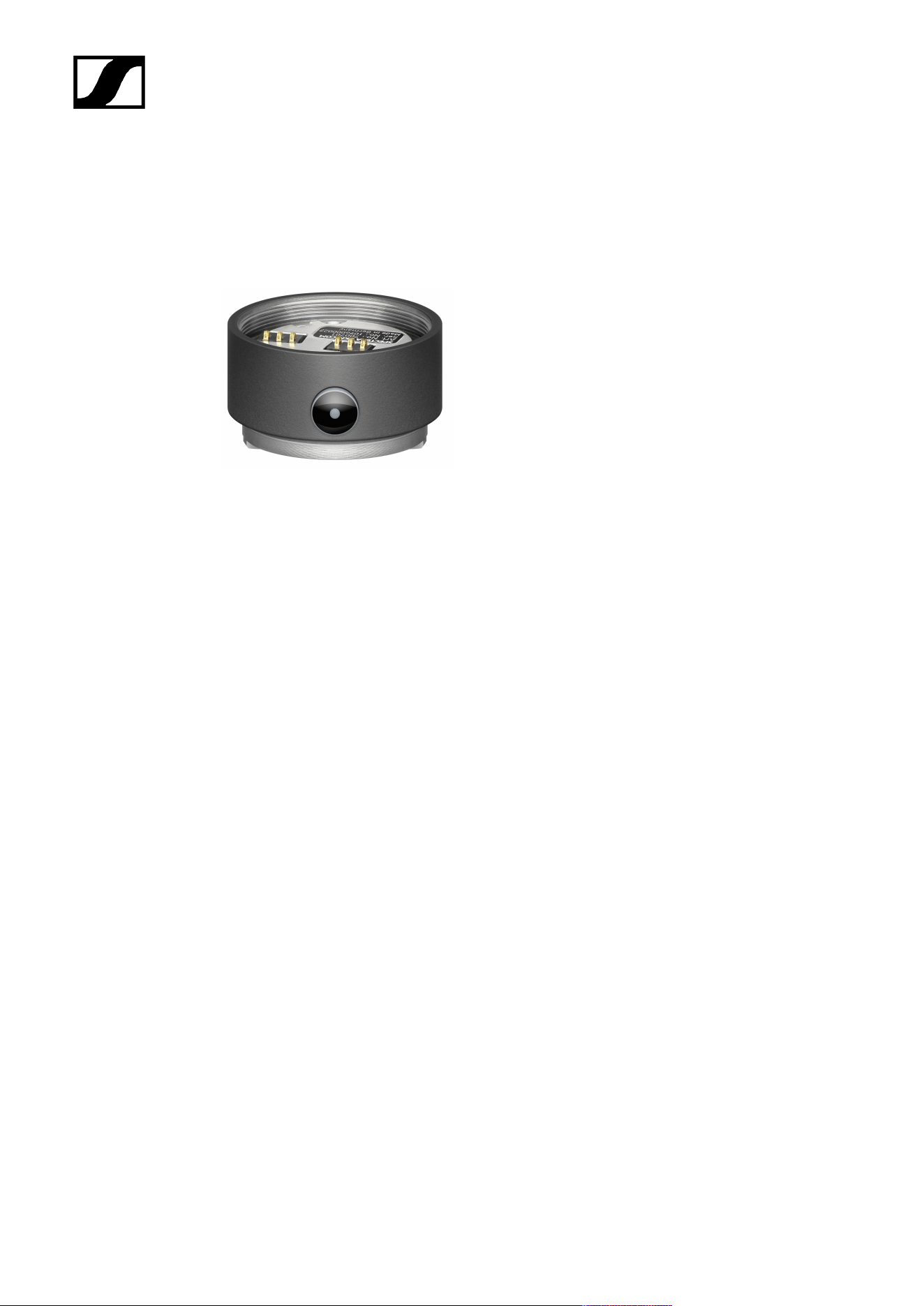
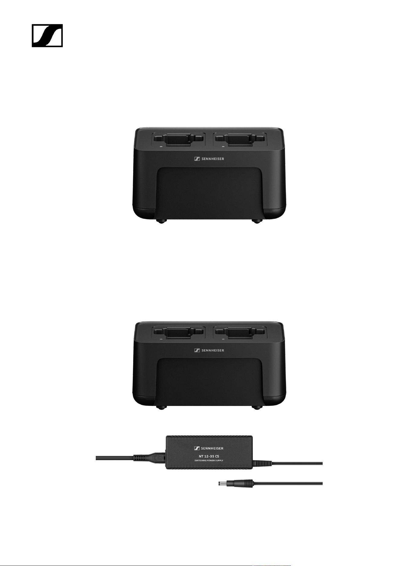
CHG 70N-C network-enabled charger
CHG 70N-C | Charger | Art. no. 700332
22

| 3 - Product information
CHG 70N-C + PSU KIT | CHG 70N-C charger with NT 12-35 CS power supply unit | Art. no.
700333
You can find more detailed information about the CHG 70N-C in the following
sections:
• Startup and operation: CHG 70N-C charger
• Specifications: CHG 70N-C charger | BA 70 rechargeable battery
23
| 3 - Product information
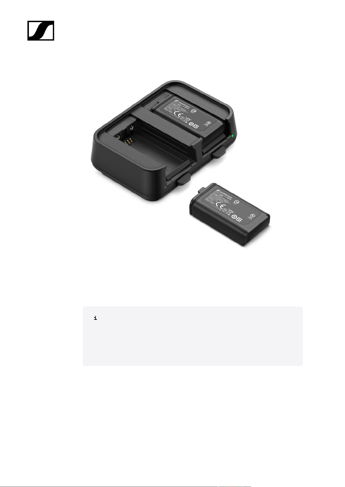
BA 70 rechargeable battery and L 70 USB charger
BA 70 | Rechargeable battery | Art. no. 508860
L 70 USB | Charger | Art. no. 508861
EW-D CHARGING SET | L 70 USB charger with two BA 70 rechargeable batteries | Art. no.
508862
You can find more detailed information about the BA 70 rechargeable battery and
the L 70 USB charger in the following sections:
• Startup and operation: L 70 USB charger
• Specifications: L 70 USB charger | BA 70 rechargeable battery
24
| 3 - Product information
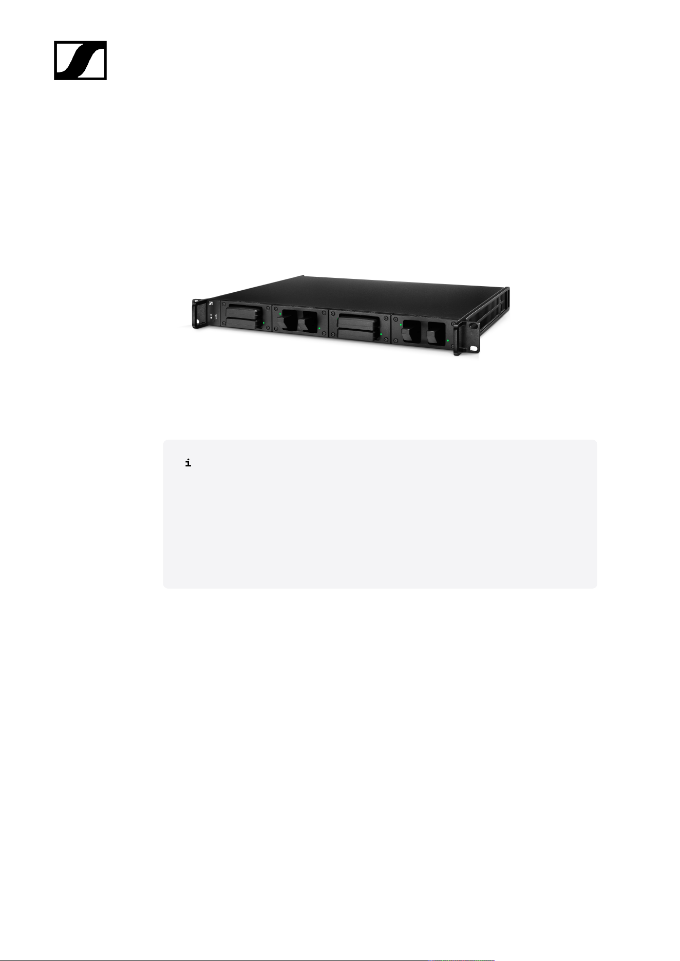
Modular L 6000 charger
The L 6000 charger is used to charge the BA 60, BA 61, BA 62 and BA 70 rechargeable
batteries.
The charging modules LM 6060 (for the BA 60), LM 6061 (for the BA 61), LM 6062 (for the BA
62) or LM 6070 (for the BA 70) are required to do so. The rechargeable batteries and charging
modules are available separately.
• L 6000 EU | Article no. 507300
You can find more detailed information about the L 6000 charger and the LM
6060, LM 6061, LM 6062 and LM 6070 charging modules in the following
sections:
• Installation and Operation: Modular L 6000 charger
• Specifications: Modular L 6000 charger and LM 6060 | LM 6061 | LM
6062 | LM 6070 charging modules
Delivery includes
• 1 L 6000 charger
• 1 mains cables (EU, UK, or US variant)
• 4 dummy caps including screws (preassembled)
• 4 rubber feet
• 1 quick guide
• 1 manual with safety instructions
• 1 manual with technical data and manufacturer declarations
Product overview
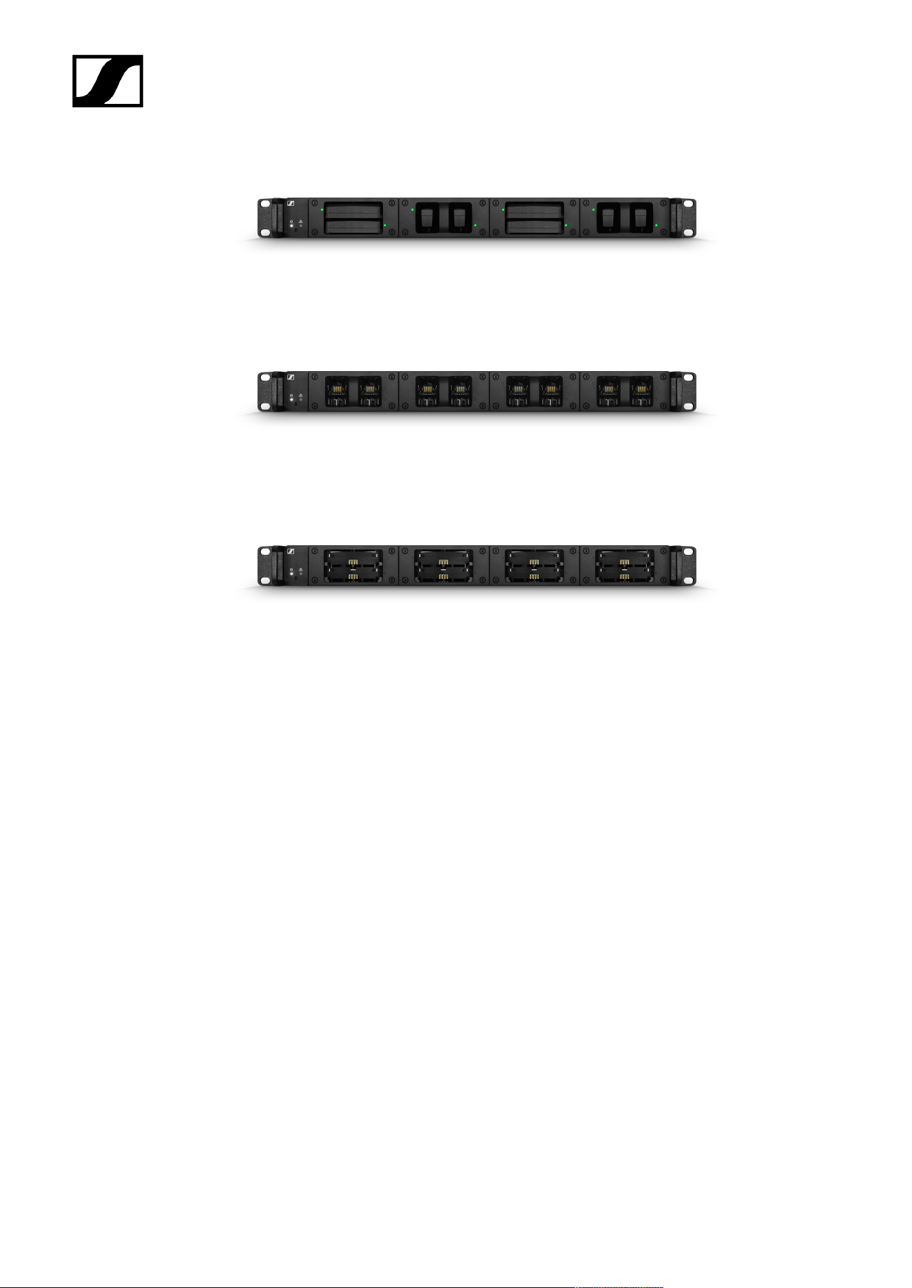
View with the charging modules and rechargeable batteries inserted:
25
| 3 - Product information
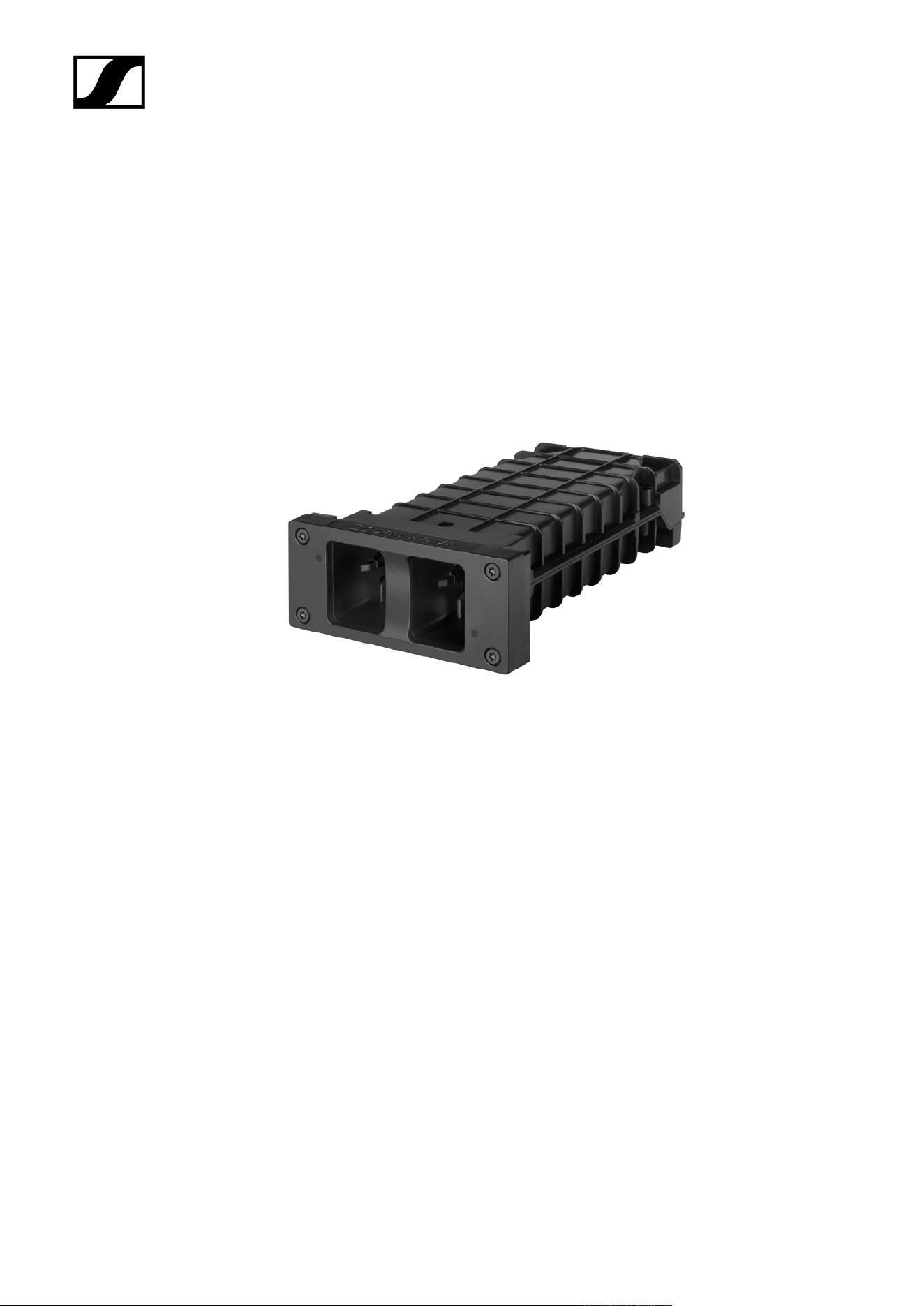
View with the LM 6060 charging modules without rechargeable batteries inserted:
View with the LM 6061 charging modules without rechargeable batteries inserted:
26
| 3 - Product information
Charging modules for L 6000 charger
The following charging modules are available for the L 6000 charger:
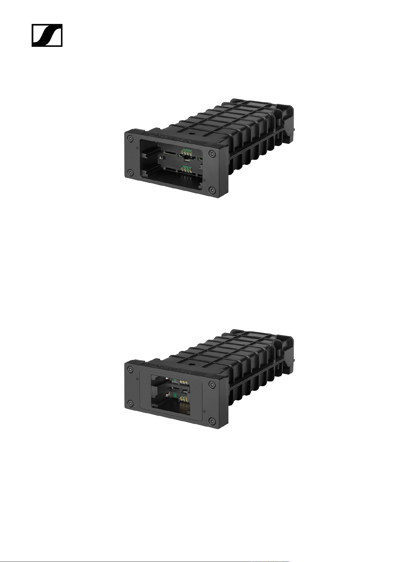
LM 6060
The LM 6060 charging module is installed in the L 6000 charger to charge the BA 60
rechargeable battery.
LM 6060 | Article no. 507198
LM 6061
The LM 6061 charging module is installed in the L 6000 charger to charge the BA 61
rechargeable battery.
LM 6061 | Article no. 507199
27
| 3 - Product information
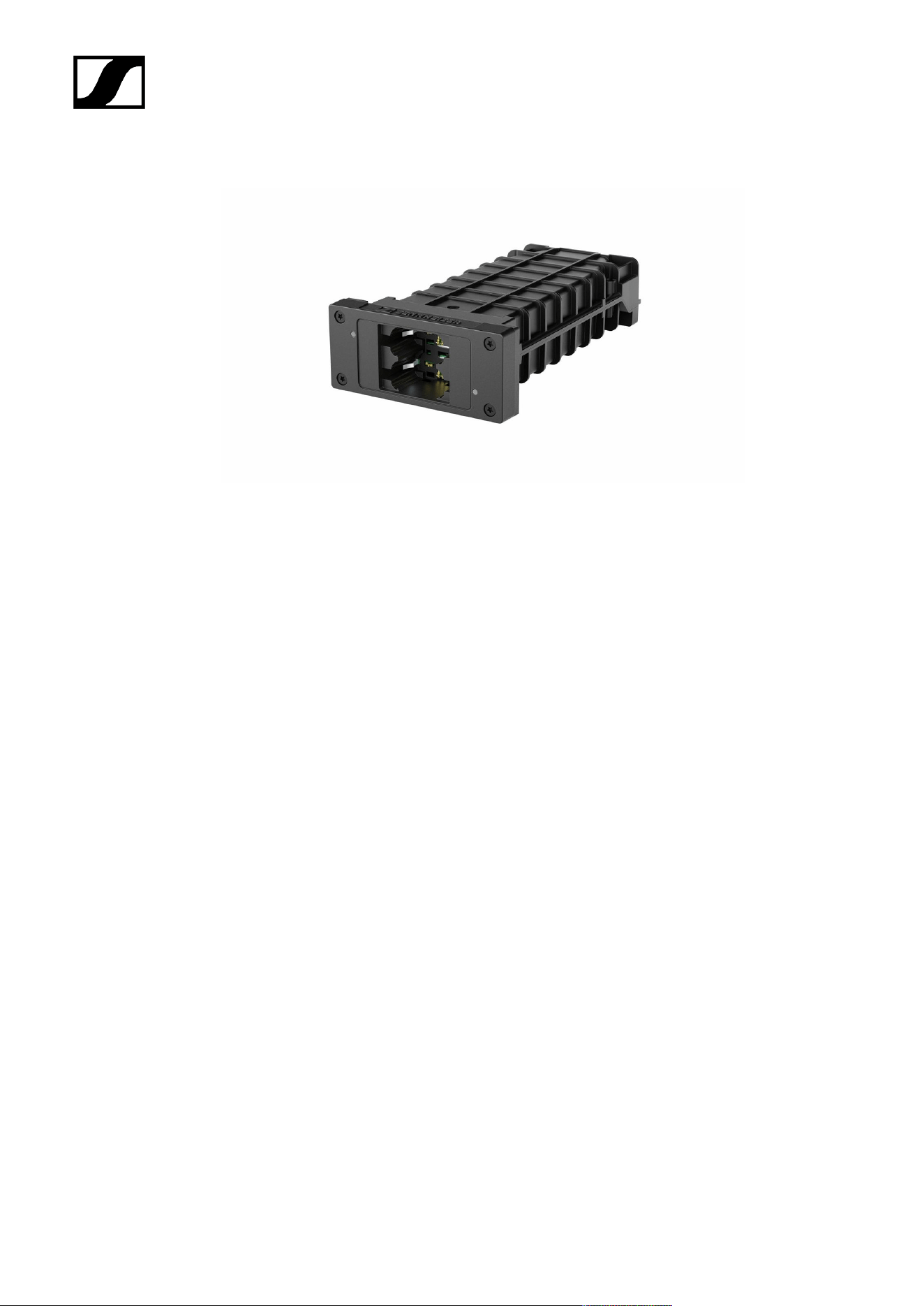
LM 6062
The LM 6062 charging module is installed in the L 6000 charger to charge the BA 62
rechargeable battery.
LM 6062 | Article no. 508516
LM 6070
The LM 6070 charging module is installed in the L 6000 charger to charge the BA 70
rechargeable battery of the Evolution Wireless Digital series.
28
| 3 - Product information
LM 6070 | Article no. 509457
29

Spectera
4. Instruction manual
Detailed description of the start-up and operation of the hardware and the WebUI.
Important Information on License Activation
NOTICE
License activation requires a direct Internet connection to the device
In order to activate the Base Station using the 18-digit license code, a direct Internet
connection is required.
Please connect your Base Station directly to a network with Internet access via
a switch or router. For more information, refer to the chapter Connecting to a
network.
Direct connections via laptop etc. are not supported for activation!
The Internet is only required once for activation.
Base Station
Get started
Get your Base Station ready to use in a few steps.
After unpacking the Base Station you must update the firmware before activating a licence.
30
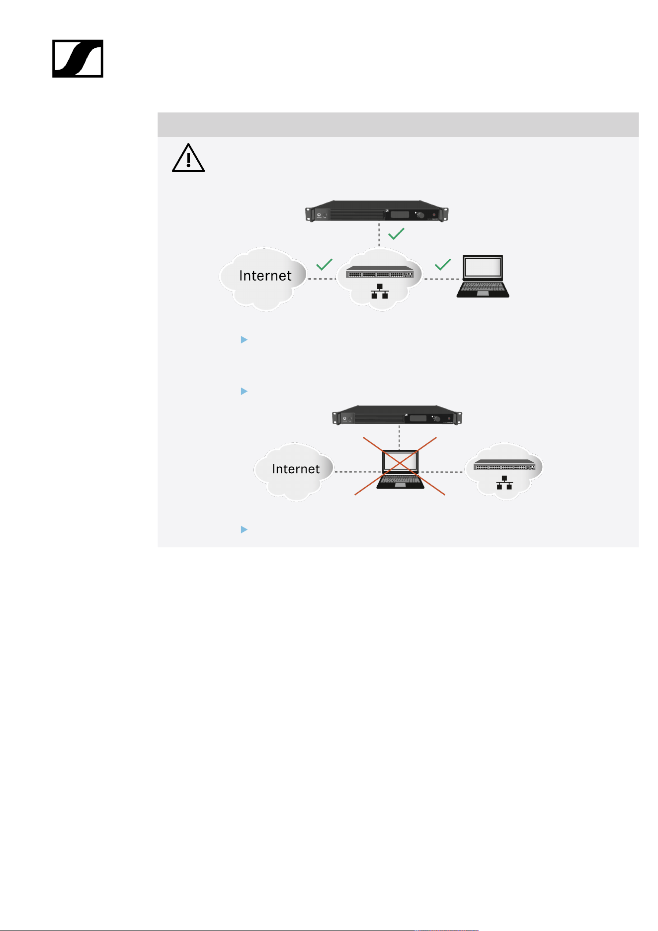
| 4 - Instruction manual
NOTICE
License activation requires a direct Internet connection to the device
In order to activate the Base Station using the 18-digit license code, a direct Internet
connection is required.
Please connect your Base Station directly to a network with Internet access via
a switch or router. For more information, refer to the chapter Connecting to a
network.
Direct connections via laptop etc. are not supported for activation!
The Internet is only required once for activation.
31
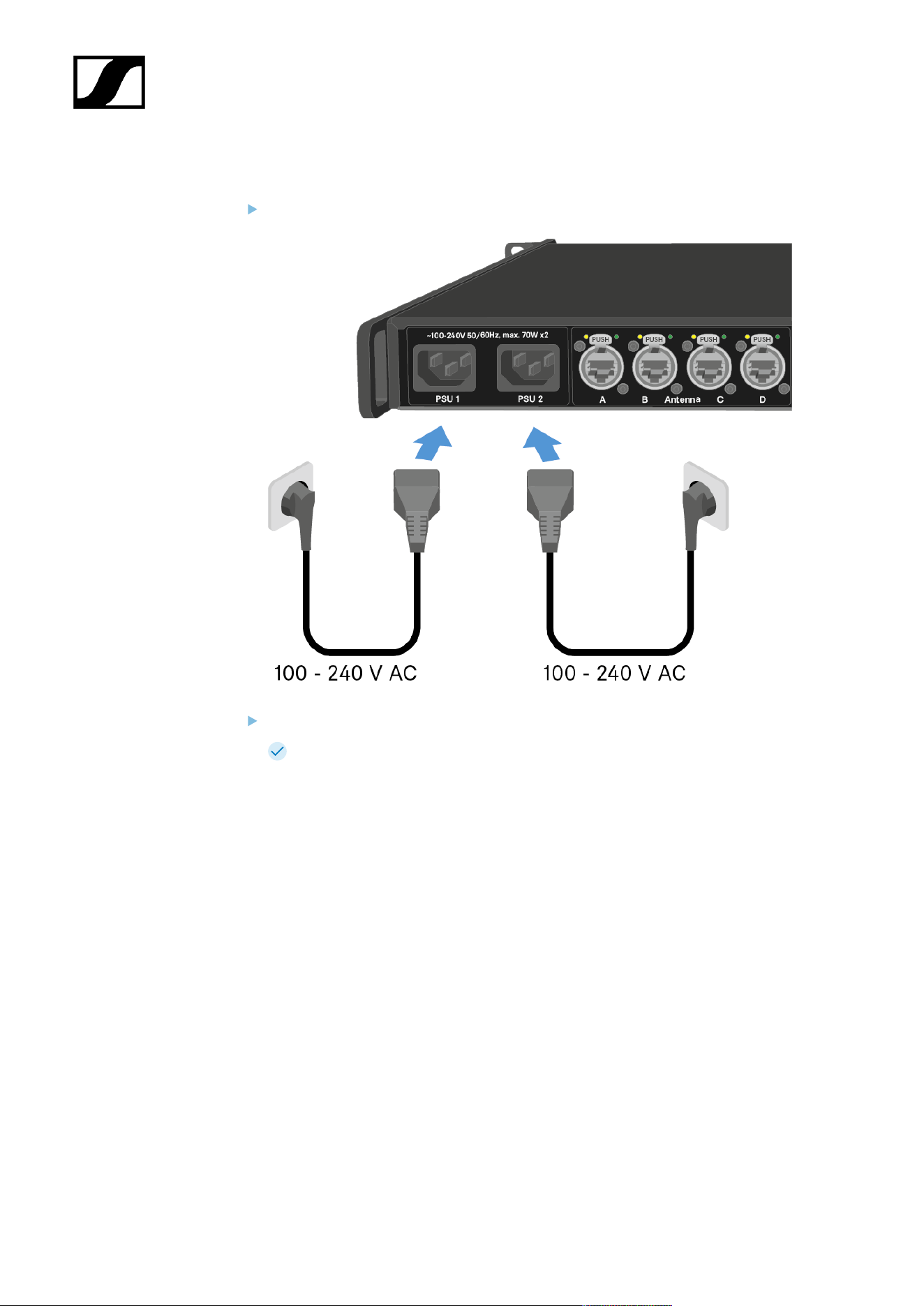
| 4 - Instruction manual
To connect the Base Station to the power supply system:
Connect one mains cable to the power socket on the rear side of the Base Station.
Connect one mains cable plug into a suitable wall socket.
The Base Station is connected to the power supply.
32
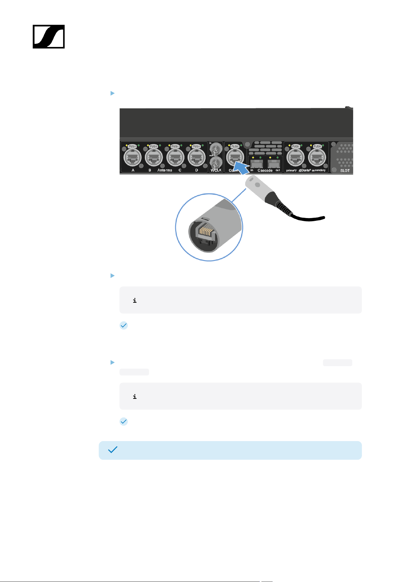
| 4 - Instruction manual
To connect the Base Station to a network:
Plug one side of the network cable into the Control socket.
Plug the other side of the network cable to a switch, router or directly to a computer.
The Base Station needs a direct Internet access!
The Base Station has been connected to a network.
To update the firmware:
To start the Spectera WebUI, enter the following URL into your browser: https://
deviceIP .
The device IP can be found here: Network.
In some cases the internet browser might have trouble showing the page.
Your Base Station is up to date.
You can now add a licence, see Activating a license (general).
33
| 4 - Instruction manual
General information for the System
Here you can find general information for your use of the System.
A license has to be activated, otherwise you cannot use the Base Station.
The Base Station has two independend RF channels. Both variants of the antenna (UHF and
1G4) can be connected to the Base Station at the same time.
You can pair up to 128 mobile devices to a Base Station within one RF channel.
Mobile devices can only be paired and operated with one Base Station at a time.
34
| 4 - Instruction manual
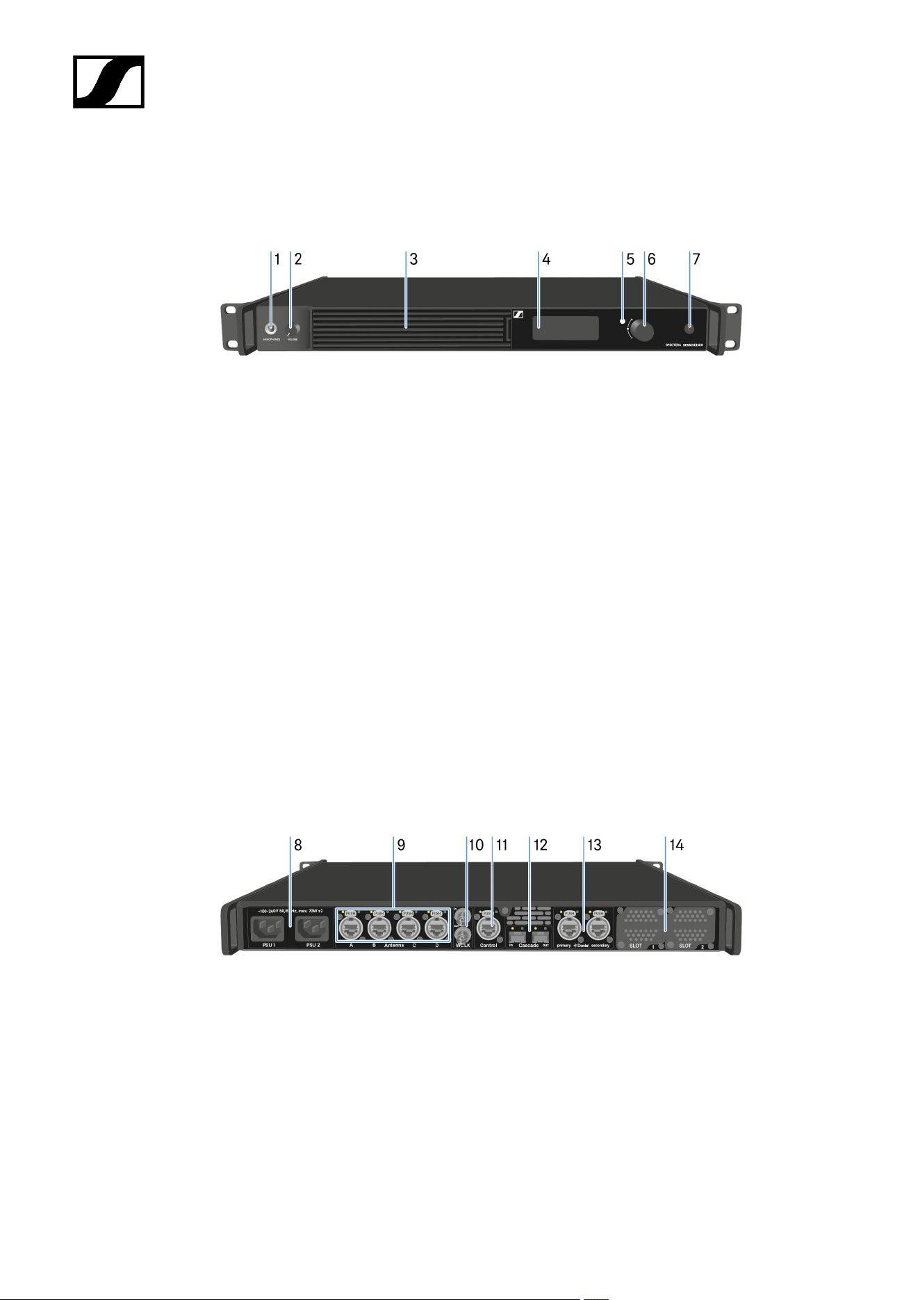
Product overview
Front
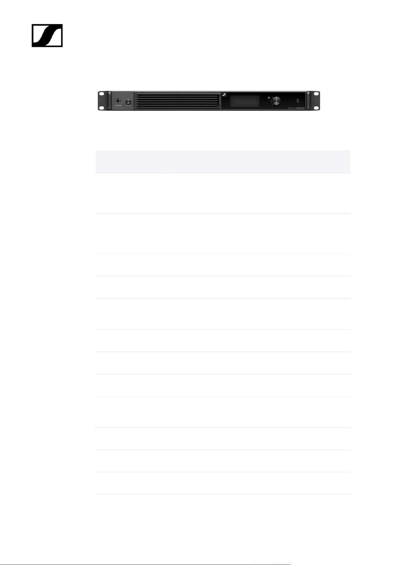
1 HEADPHONES socket
see Using the headphone output
2 VOLUME control for headphone
see Using the headphone output
3 Fan inlet with filter
see Changing the fan filter
4 Display for status information and operating menu
see Information on the display
5 LED to indicate the status
see Meaning of the LED
6 Jog-Dial (UP/DOWN/SET) for navigating the menu
see Navigating the menu
7 ON/OFF button
see Switching the Base Station on and into standby
Back
8 Power socket
see Connecting/disconnecting the Base Station to/from the power supply
system
9 4x ruggedized RJ45 Antenna ports
see Connecting antennas
10 Word clock in/out
see Connecting word clock
35

| 4 - Instruction manual
Installing slot-in cards
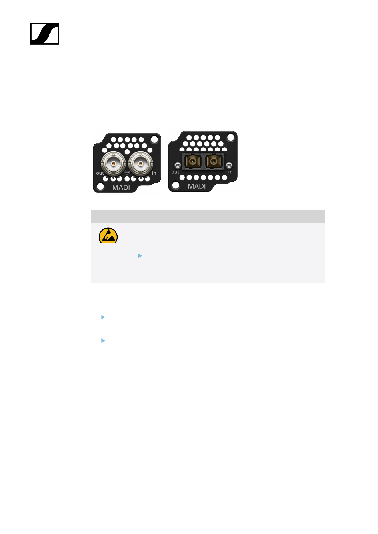
The same or different cards can be installed.
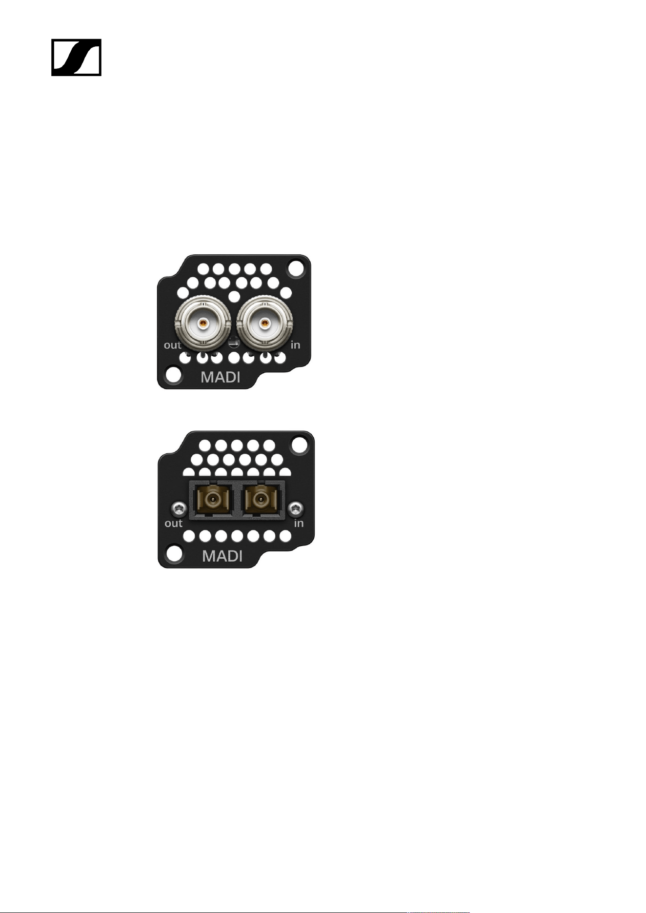
Two types of MADI Cards are available, see MADI Cards.
Madi CARD (BNC) Madi CARD (OM)
CAUTION
Improper handling of the device may result in its damage
Device contains sensitive electronics to electrostatic discharge (ESD).
Observe the precautionary measures for handling components
at risk of electrostatic discharge and take appropriate protective
measures when touching the device.
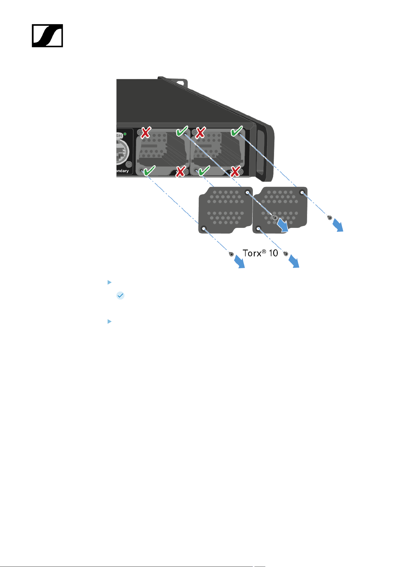
To install a MADI Card in the Base Station:
Completely disconnect the Base Station from the power supply system. See
Connecting/disconnecting the Base Station to/from the power supply system.
Unscrew one of the dummy caps on the Base Station. To do so, you require a torx® 10
screwdriver.
37
| 4 - Instruction manual
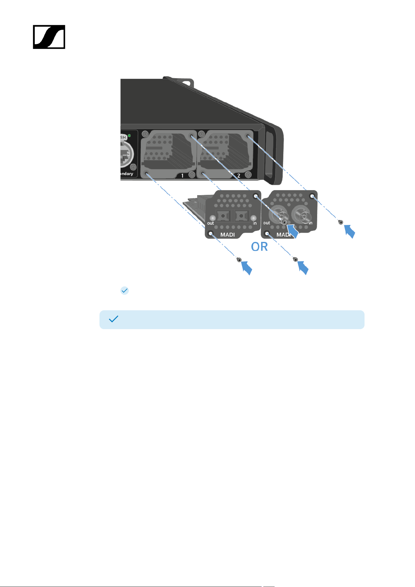
Fully slide the MADI Card into the open slot as shown in the figure.
The card can be inserted into the Base Station housing only in one direction. The
lettering on the card must face upward.
Tightly screw on the MADI card with max. 65 cNm +/-10%.
38
| 4 - Instruction manual
The MADI Cards can be used directly.
A MADI Card has been installed.
39

| 4 - Instruction manual
Connecting/disconnecting the Base Station to/from the power
supply system
Optional for redundancy you can connect the Base Station with two cables. The optional
cable is not included.
To connect the Base Station to the power supply system:
Connect one mains cable to the power socket on the rear side of the Base Station.
Connect one mains cable plug into a suitable wall socket.
The last state is restored: on or standby.
For redundancy connect an other cable (not included) as well.
The Base Station is connected to the power supply.
To completely disconnect the Base Station from the power supply system:
Unplug both mains cable plugs from the wall socket.
Unplug both mains cable from the power socket on the rear side of the Base Station.
The Base Station is completely disconnected from the power supply.
40

| 4 - Instruction manual
The Base Station has been connected/disconnected successfully.
41
| 4 - Instruction manual
Connecting to a network
Connect the Base Station to a network for monitoring and controlling.
To connect the Base Station to a network:
Plug one side of the network cable into the Control socket.
Plug the other side of the network cable to a switch, router or directly to a computer.
42
| 4 - Instruction manual
NOTICE
License activation requires a direct Internet connection to the device
In order to activate the Base Station using the 18-digit license code, a direct Internet
connection is required.
Please connect your Base Station directly to a network with Internet access via
a switch or router. For more information, refer to the chapter Connecting to a
network.
Direct connections via laptop etc. are not supported for activation!
The Internet is only required once for activation.
See Activating a license (general).
The Base Station has been connected to a network.
You can monitor and control the Base Station via a network connection using Spectera
WebUI.
To start the Spectera WebUI, enter the following URL into your browser: https://
deviceIP .
The device IP can be found here: Network.
43
| 4 - Instruction manual
Connecting antennas
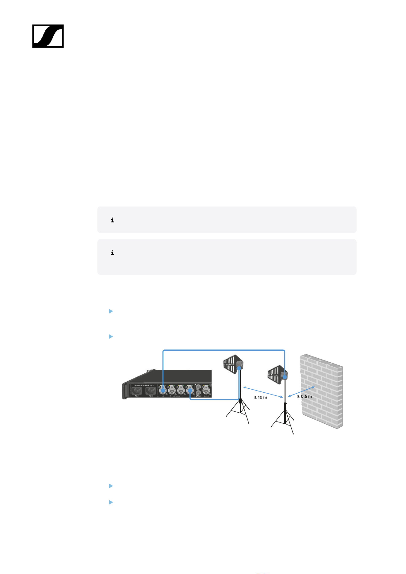
You can connect up to four antennas to the Base Station.
Recommandations regarding the antenna setup:
• Keep a distance more than 10 m (393.7") between the antenna and another antenna.
• Keep a distance more than 0.5 m (19.69") between the antenna and a wall.
The cable must
• be a CAT5e or higher,
• have ruggedized plugs and
• not extend 100 m (3937").
We recommend using a antenna cable cat 5e (see Accessories for the DAD).
Both variants (UHF and 1G4) can be connected to the Base Station at the same
time.
To connect an antenna to the Base Station:
Plug on side of the cable into one antenna port (A, B, C or D) at the rear side of the
Base Station.
Plug the other side of the cable into an antenna.
We recommend a distance greater than 10 m (393.7") for an optimal RF performance.
To disconnect an antenna from the Base Station:
Hold down the push button.
Unplug the cable from the Base Station.
44
| 4 - Instruction manual
The Base Station has been connected to/disconnected from an antenna.
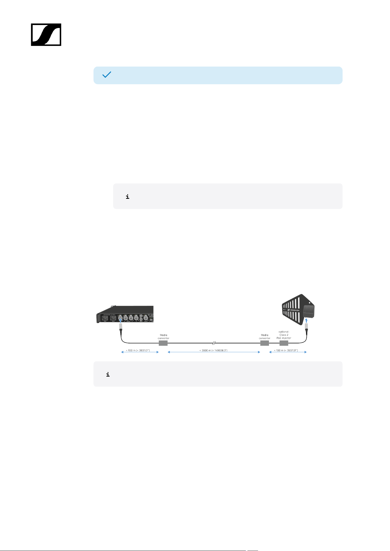
Antenna cable extension
Longer cable distances are possible with the use of fiber optic cables and media
converters.
Sennheiser tested the recommend converters for a complete distance of 4 km (157480.31").
We only recommend the following converters for fully tested functionality:
• Base Station:
Do not use converters with PoE to connect to the Base Station.
• Lantronix M/GE-T-SFP-01
• DAD:
• Lantronix M/GE-PSW-PSE-01 (with PoE only for DAD)
• Lantronix M/GE-T-SFP-01 (needs a Class 2 PoE injector capable of supplying
powering to the DAD (power consumption < 6.5 W))
• Barnfind Technologies BarnColor 4xEth (with PoE only for DAD)
• StarTech.com Industrial PoE Media Converter (Product ID: IMC1GSFP30W)
(with PoE only for DAD)
The media converter must not have a switch function.
45
| 4 - Instruction manual
Connecting word clock
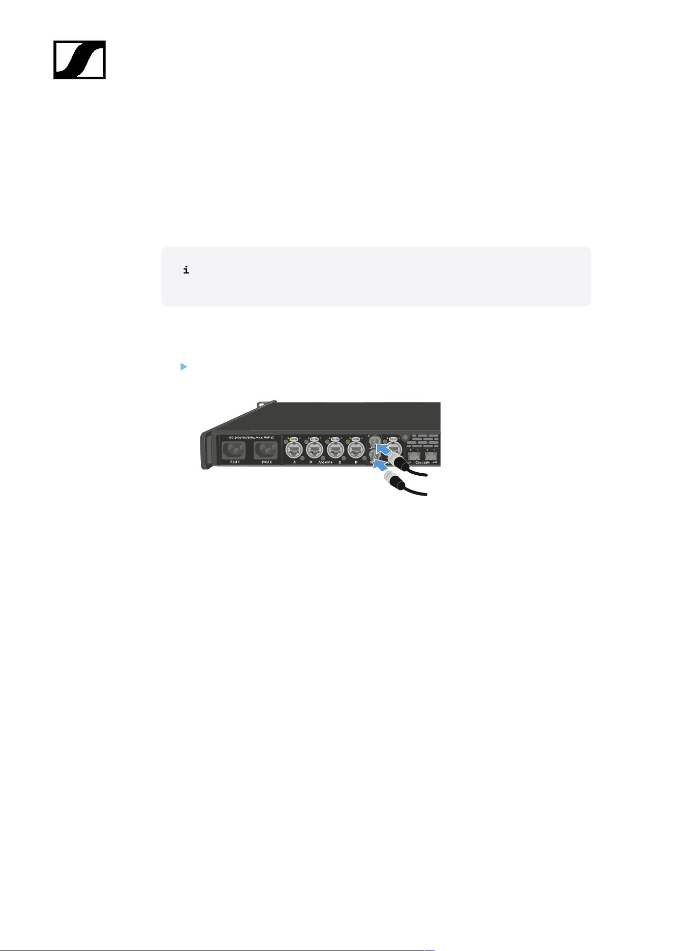
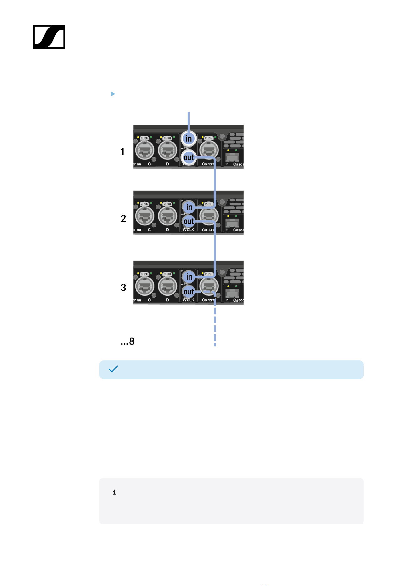
You can use the internal word clock on the Base Station or connect an external word clock.
You can also output the external word clock and cascade it up to 8 Base Stations.
The word clock output transmits only the external word clock that is connected via the word
clock input. The internal word clock is not output via the word clock output.
For more information about the word clock, see Word clock scenarios for digital
audio.
To connect an external word clock:
Use a coaxial BNC cable (75 Ω) to connect the external word clock to the word clock
in input.
46
| 4 - Instruction manual
To cascade the word clock:
Connect the cable from the word clock in input of the next Base Station to the word
clock out output of the previous Base Station.
The Base Station has been connected to word clock.
Word clock scenarios for digital audio
The Base Station supports two clock rates: 48 kHz and 96 kHz.
You can use either the internal word clock on the Base Station or connect an external word
clock.
An external word clock can also be forwarded to a downstream device via the word clock
output. This feature allows you to cascade up to 8 Base Station devices.
Note that only the word clock on the word clock input can be forwarded via the
word clock output. The internal word clock is not forwarded via the word clock
output.
47
| 4 - Instruction manual
Word clock with digital audio
If multiple devices with digital audio signals are connected in a production environment,
their clock signals must be synchronized via a word clock, otherwise audio errors occur. The
word clock of one device becomes the master. All of the other devices become slaves and
synchronize with the master.
Dante®
The Audinate Brooklyn III Dante® interface installed in the Base Station should be understood
as a standalone digital audio device with its own word clock and also has to be clocked either
internally or externally.
You require the Dante Controller software from Audinate for these settings. You
can access it using the link: Dante Controller.
Defining the master and slave
The Base Station word clock input, the Base Station internal word clock, the word clock
of the Audinate Brooklyn III Dante® interface, or the Dante® network can be defined as the
master.
For WebUI see: Audio interfaces.
48
| 4 - Instruction manual
Connecting audio via Dante®
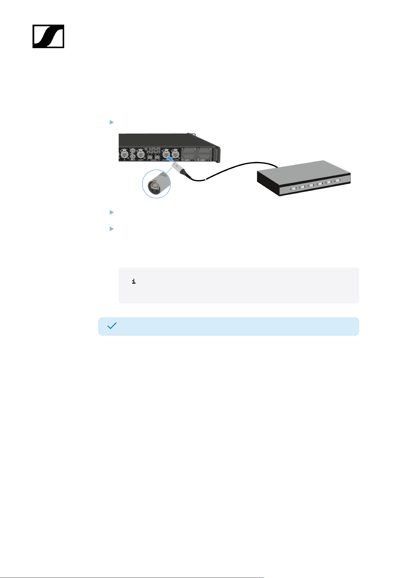
You can input and output audio via Dante®.
To connect audio via Dante®:
Plug one side of a ruggedized RJ45 cable to the Dante® primary socket.
Plug the other side into a router.
Download the Dante® Controller.
This is typically a host computer (PC or Mac), with the Dante® Controller software
application installed. This application configures and controls all the Dante® devices
and audio streams inside the network.
Information about the Dante Controller and the Dante® network protocol
settings is available on the Audinate website: audinate.com.
The Base Station can input and output audio via Dante®.
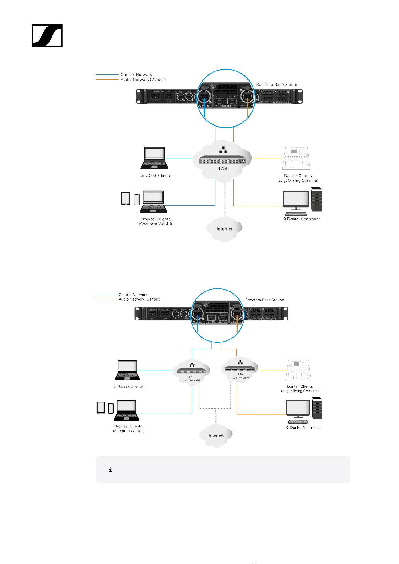
Shared network mode
In Shared Network Mode both networks for Control and Dante® are using the same physical
network infrastructure.
49
| 4 - Instruction manual
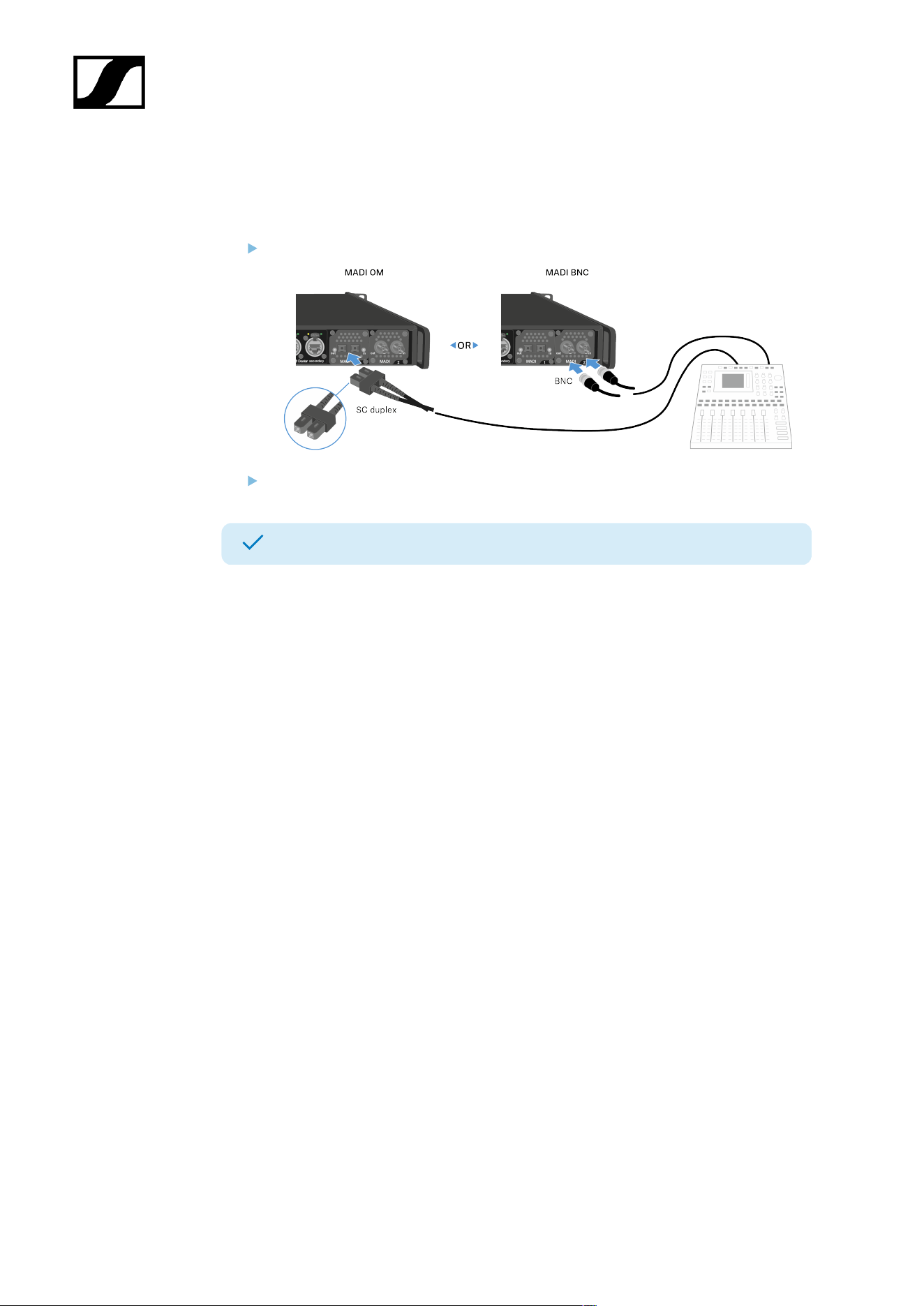
Split Network Mode
In Split Network Mode both networks for Control and Dante® are using different physical
network infrastructure.
For more information, please refer to the Network guide.
50
| 4 - Instruction manual
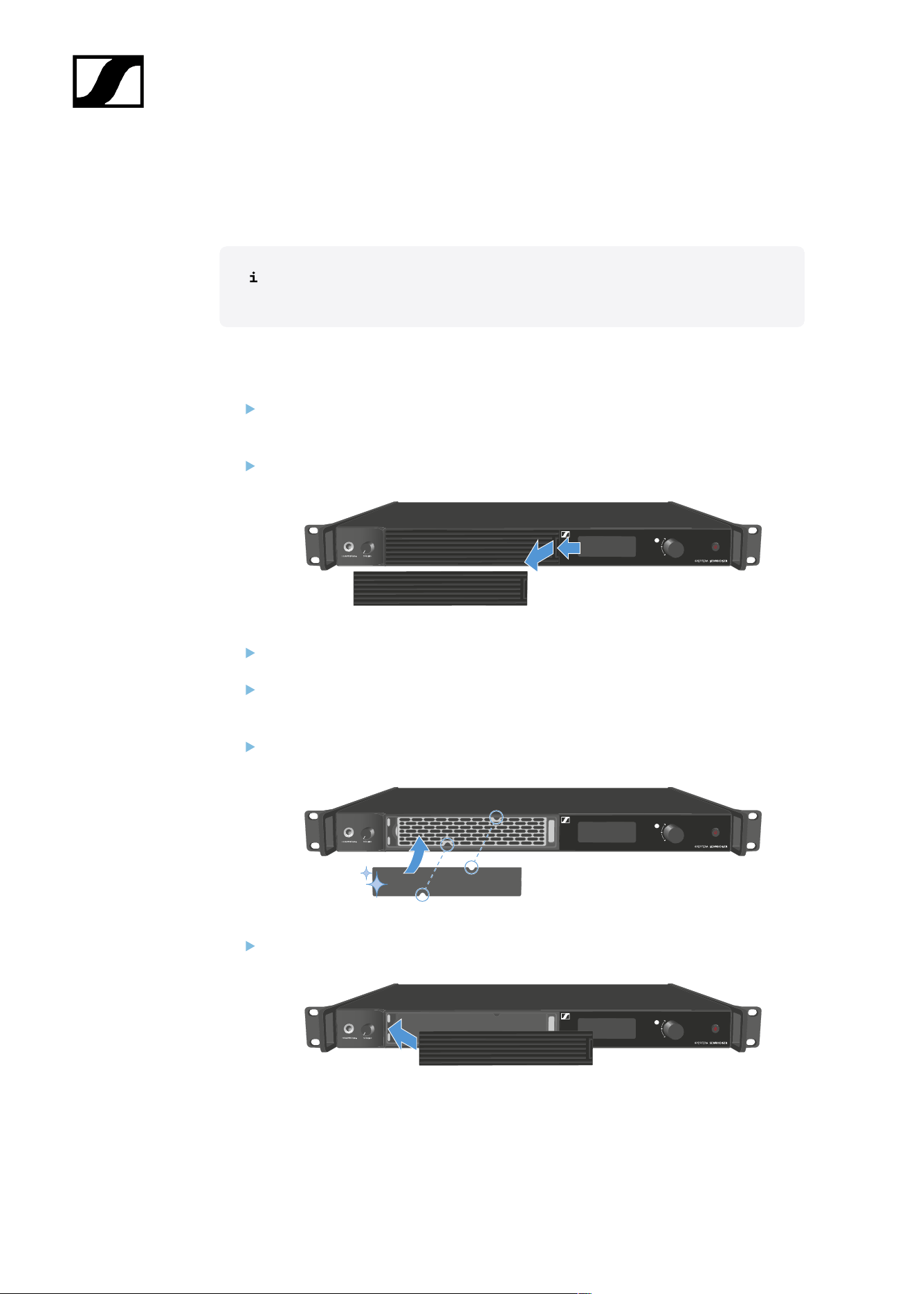
Connecting audio via MADI
To connect audio via MADI:
Plug one side of the (BNC or OM) cable to the installed MADI card.
Plug the other side of the cable to a mixing console.
The Base Station can input and output audio via MADI.
51
| 4 - Instruction manual
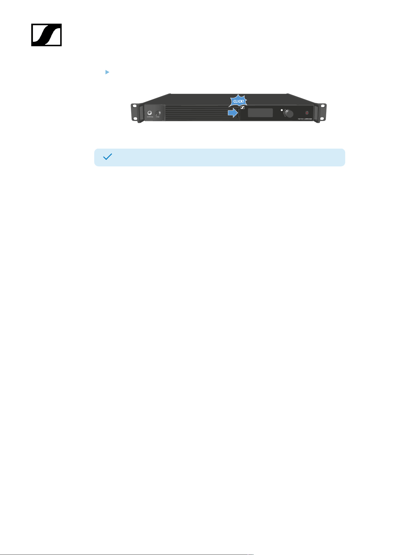
Changing the fan filter
The filter protects the fans from dust.
Check the filter from time to time and replace it to ensure safe operation and
sufficient cooling.
To change the filter:
Switch the Base Station into standby. See Switching the Base Station on and into
standby.
Push down the release and pull the cover forward at the same time.
Remove the filter and dispose it properly.
Place a new filter in the Base Station.
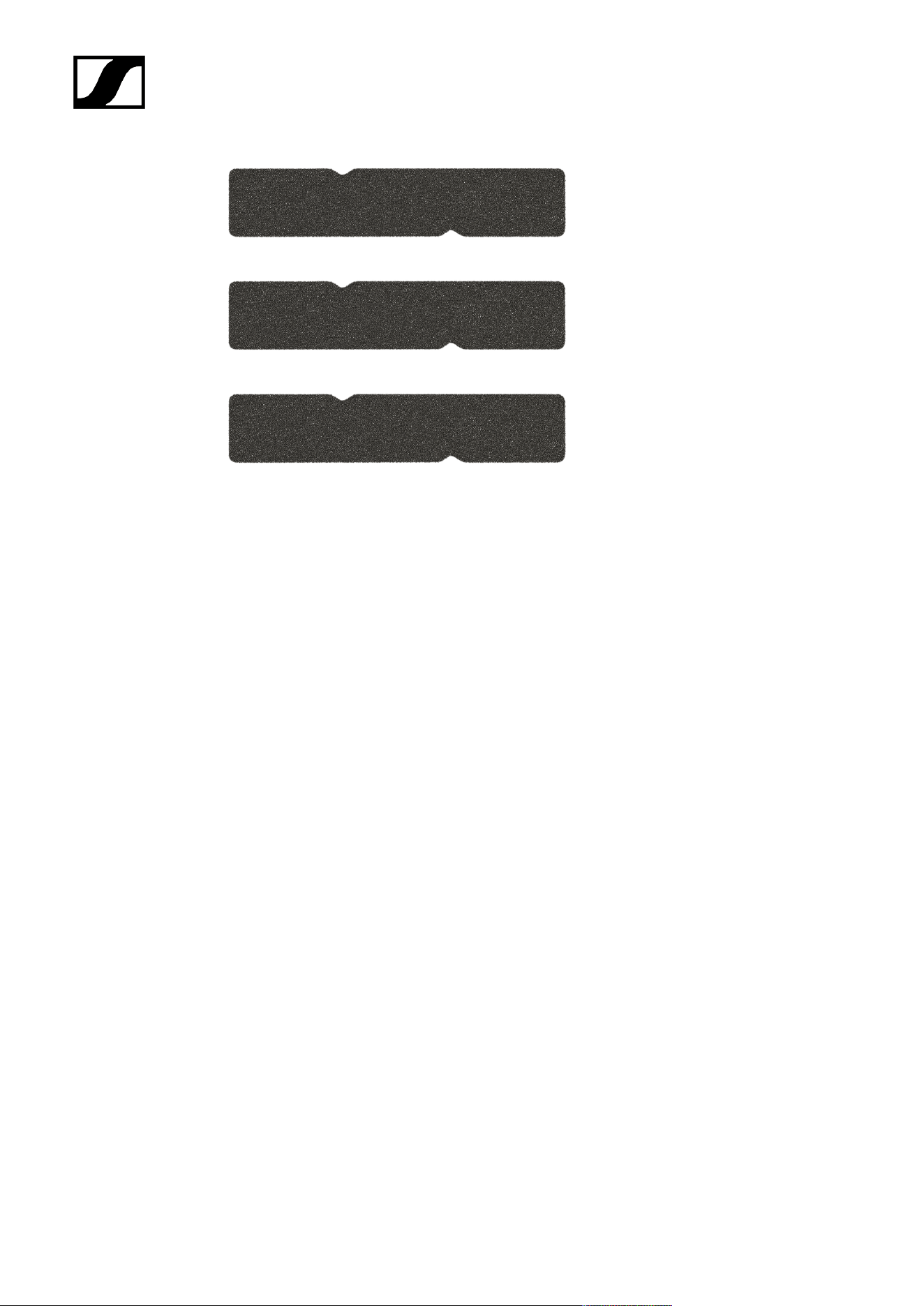
Information about new filter can be found here: Spectera Filter set.
Make sure that the recesses match those in the device.
Slide the cover into the left side.
52
| 4 - Instruction manual
On the right side, press the cover firmly until you hear it click into place.
The filter has been replaced.
53
| 4 - Instruction manual
Installing the Base Station in a rack
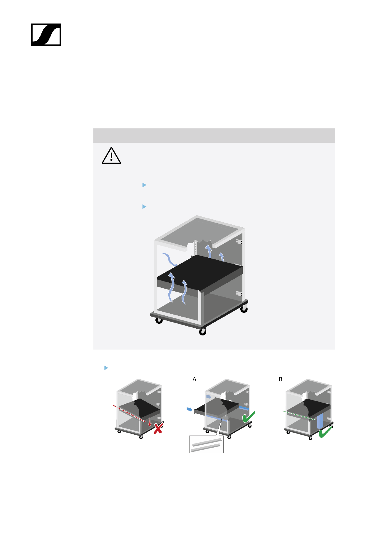
You can install the Base Station in any conventional 19" rack. The rack mounting angles are
already attached to the device.
Always observe the following information during rack mounting.
NOTICE
Material damages caused by devices overheating
When there is insufficient ventilation, the devices mounted in the rack
may overheat.
Ensure that there is sufficient ventilation in the rack, particularly
if several devices are installed.
If necessary, install a fan in the rack.
Support the Base Station after installation in the rack.
Due to the weight and depth of the device, there is a risk that it may break off in the
rack and become damaged as a result.
54

| 4 - Instruction manual
Version A
Use special rack mounting rails.
The design of the rack used must be suitable for the installation of these mounting
rails.
Version B
Use a suitable object to support the device on the rear side.
Ensure that this object cannot become loose.
The Base Station has been installed in a rack.
55

| 4 - Instruction manual
Switching the Base Station on and into standby
The Base Station cannot be switched off. You have to disconnect it from the
power supply, see Connecting/disconnecting the Base Station to/from the
power supply system.
To switch the Base Station on:
Short-press the ON/OFF button.
The Sennheiser Logo appears in the display and the Base Station is booting.
When booting is done, the power button LED lights up white.
To switch the Base Station into standby:
Long-press the ON/OFF button.
The display and the LED go off. The ON/OFF button pulses white.
The DAD goes off.
The Base Station has been switched on/into standby.
56
| 4 - Instruction manual
Activating a license (general)
A license has to be activated, otherwise you cannot use the Base Station.
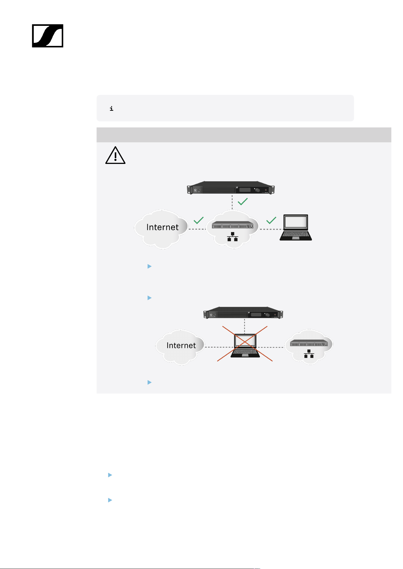
NOTICE
License activation requires a direct Internet connection to the device
In order to activate the Base Station using the 18-digit license code, a direct Internet
connection is required.
Please connect your Base Station directly to a network with Internet access via
a switch or router. For more information, refer to the chapter Connecting to a
network.
Direct connections via laptop etc. are not supported for activation!
The Internet is only required once for activation.
The license specifies the country-specific frequency ranges and the RF power.
You can activate a license via Spectera WebUI.
Only one license per Base Station is possible.
To activate a license:
Connect the Base Station to the power supply, see Connecting/disconnecting the
Base Station to/from the power supply system.
Connect the Base Station to a network via a switch or router, see Connecting to a
network.
57
| 4 - Instruction manual
The Base Station needs a direct Internet access!
Connect a computer to the same switch or router.
If you want to activate a license via Spectera WebUI, follow the steps described here:
Activating a license (WebUI).
Check the product page sennheiser.com/base-station for the latest firmware.
A license has been activated.
58
| 4 - Instruction manual
Using the headphone output
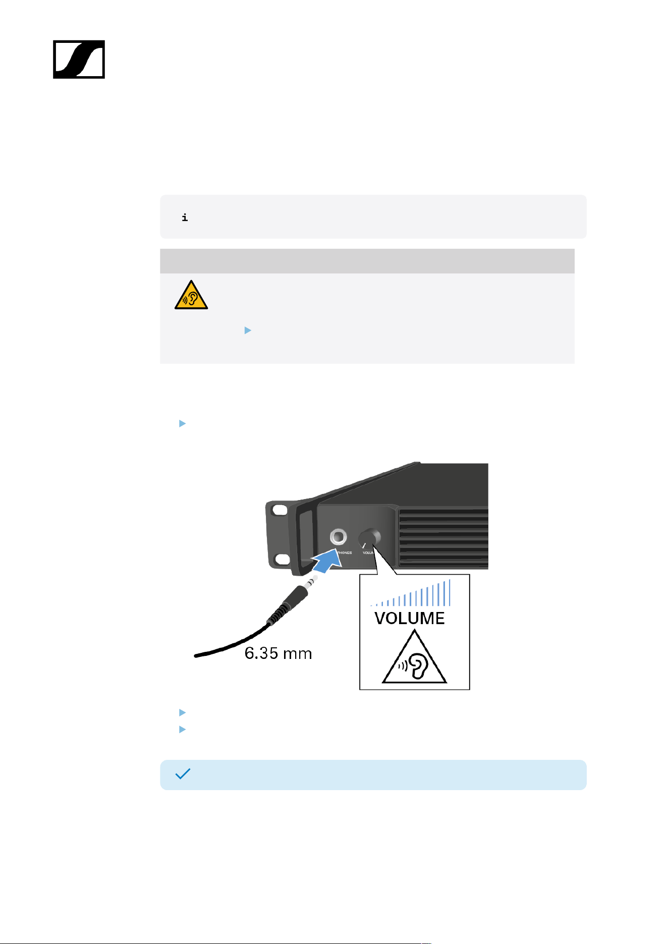
You can use the headphone output on the front of the Base Station (6.35 mm jack) to listen
to the audio signals of the channels.
First you have to set up audio links in Spectera WebUI.
WARNING
Danger due to high volume levels
Volume levels that are too high may damage your hearing.
Turn down the volume of the headphone output before you put on
the headphone.
To listen to an audio source:
Connect the headphone to the HEADPHONES socket.
You can select the audio source here: Headphone.
Control the volume by turning the VOLUME control next to the HEADPHONES socket.
You can now listen to the selected audio source.
59
| 4 - Instruction manual
Meaning of the LED
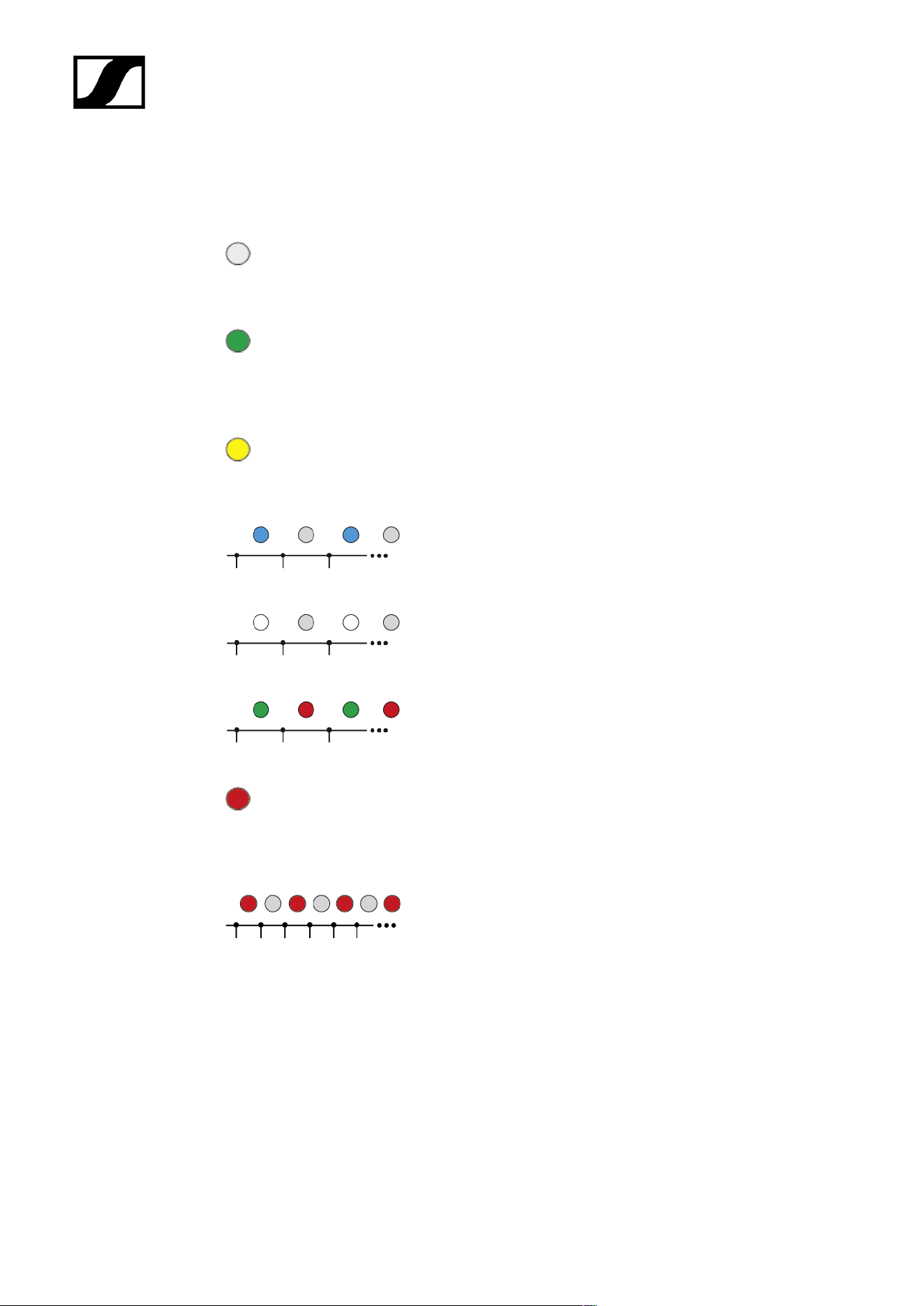
The LED on the front of the Base Station indicates the following information.
The LED is off:
• Base Station is in standby.
The LED is green:
• Base Station is on and one or both RF channels are
active.
The LED is yellow:
• One or both RF channels are muted.
The LED is flashing blue:
• Paring is enabled.
The LED is flashing white:
• The Base Station is identified.
The LED is flashing green and red:
• Firmware update is in progress.
The LED is red:
• Base Station is working, but shows a warning on the
display.
The LED is flashing red quickly:
• Error. Base Station is not working and shows a warning
on the display.
60
| 4 - Instruction manual
Information on the display
Basic information are shown on the display.
The display goes into screen saver after some time.
You can wake up the display by pressing or turning the jog-dial.
The display shows the operating menu, which can be used to configure a few settings (see
Menu structure).
More options and other parameters are available in Spectera WebUI!
To navigate the menu, see Navigating the menu.
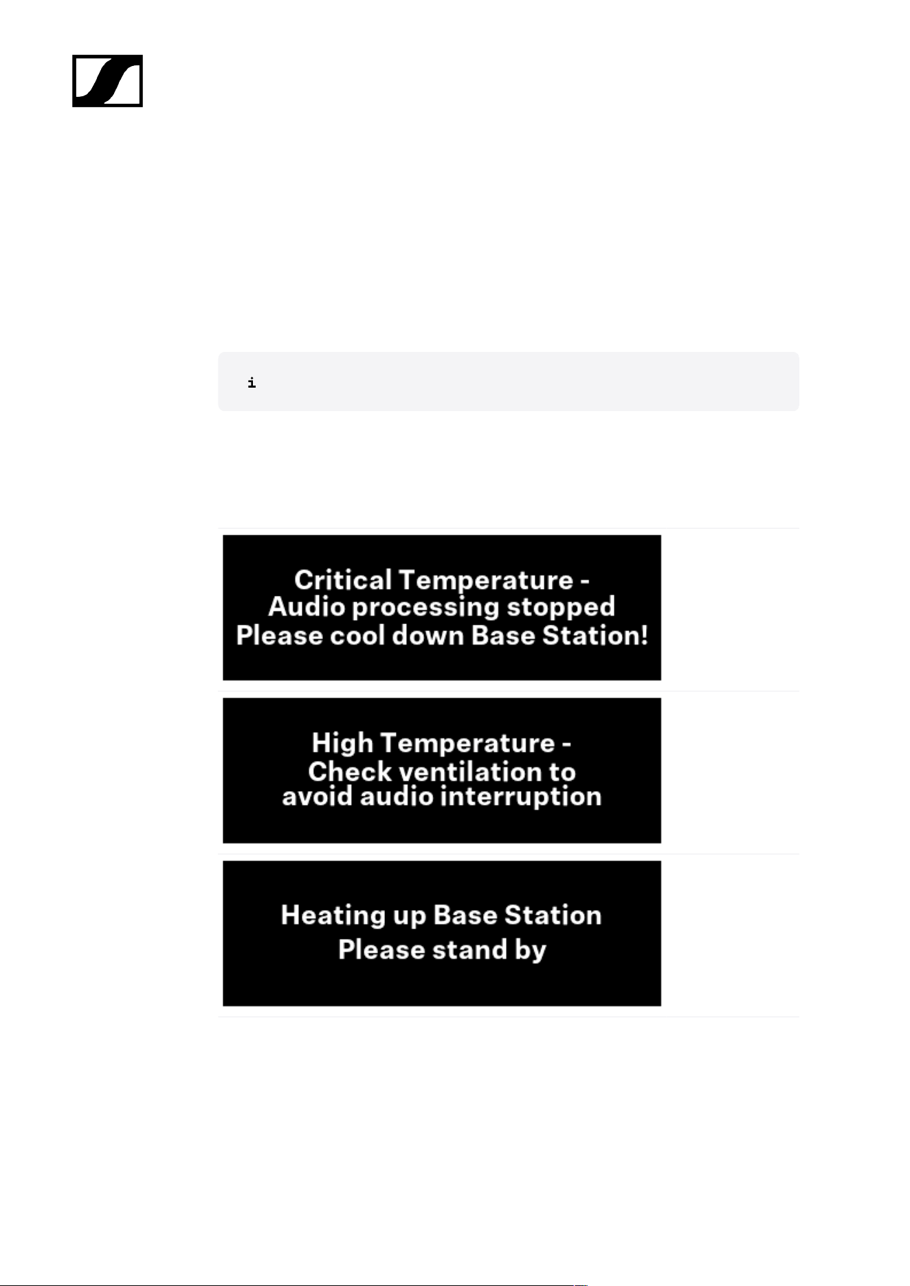
Status messages
In certain situations, status messages may appear on the display.
Error - The
temperature
is critical. The
audio processing
stopped. Cool down
the Base Station.
Warning - The
temperature is
high. Check the
ventilation to avoid
audio interruption.
Warning - The
temperature is low.
The Base Station is
heating up. Please
stand by.
61
| 4 - Instruction manual
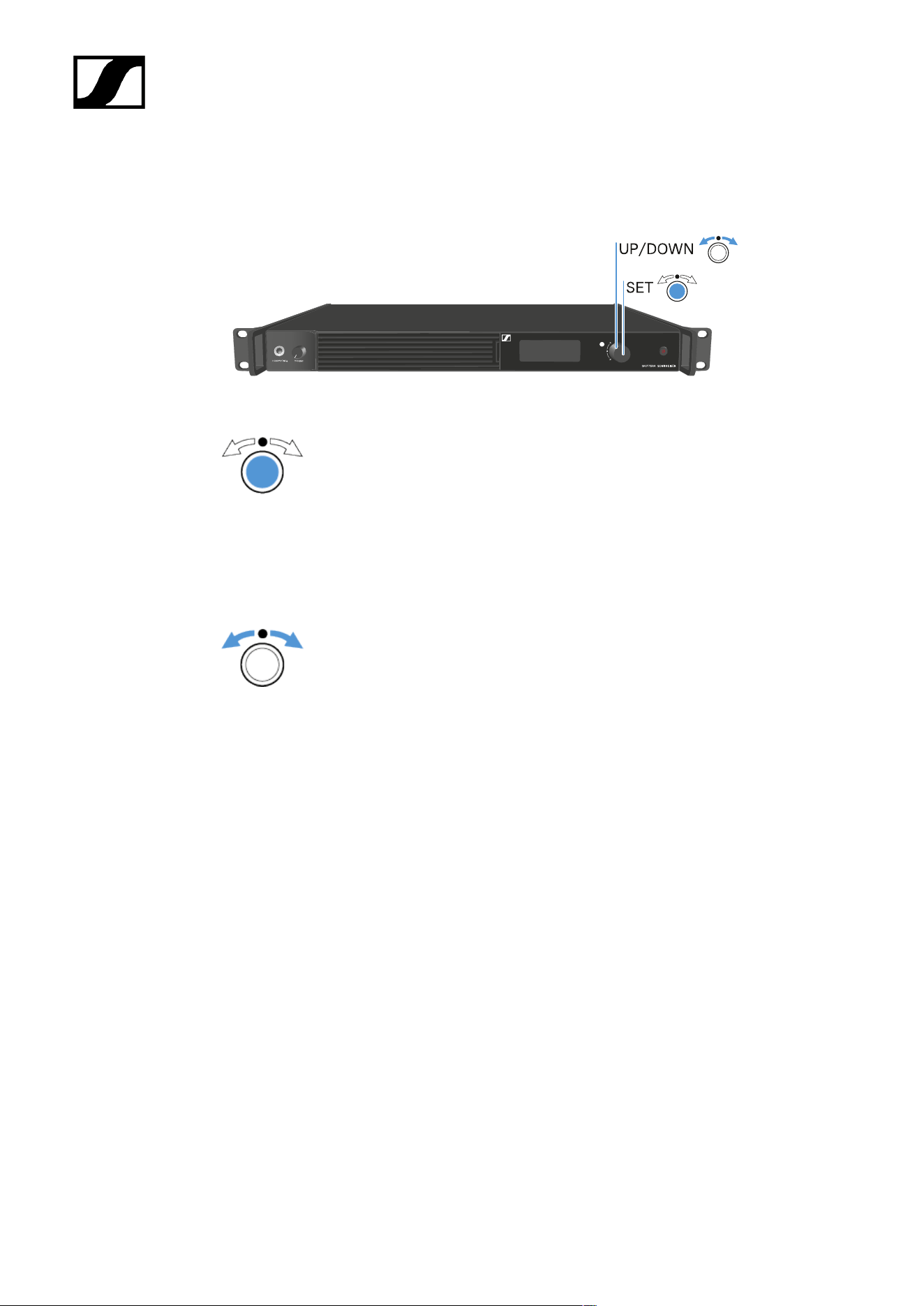
Navigating the menu
Use the jog-dial to navigate through the operating menu.
Press the jog dial
• Calls up a menu item
• Changes to a submenu
• Saves settings
Turn the jog dial
• Changes to the previous or next menu item
• Changes the setting of a menu item
62
| 4 - Instruction manual
Menu structure
In the Base Station menu, you can configure a few settings.
More options and other parameters are available in Spectera WebUI!
The following settings can be changed:
Mute/Unmute the RF-Channels
• Main menu
Change the IP mode
• Network
Select the audio source for the headphone
• Headphone
Reset the Base Station
• Reset
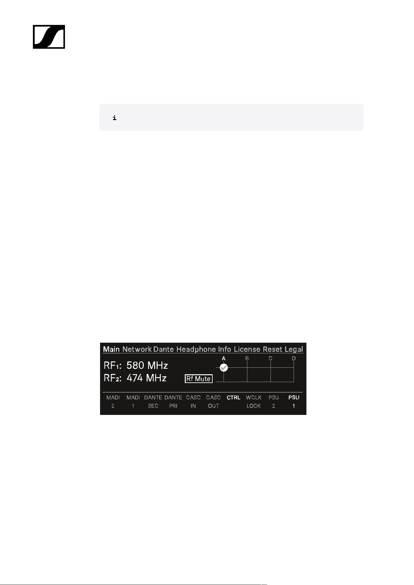
Main menu
In this menu item, you can view information about connections.
In the upper part you can view information about the RF channel:
• The selected frequency
• The state of the antenna (mute, active)
• Which antenna port is used for the RF channel.
In the lower part you can view information about the used connection:
• Connected ports are highlighted.
• The order corresponds to the ports on the back.
63
| 4 - Instruction manual
To mute/unmute the RF channel:
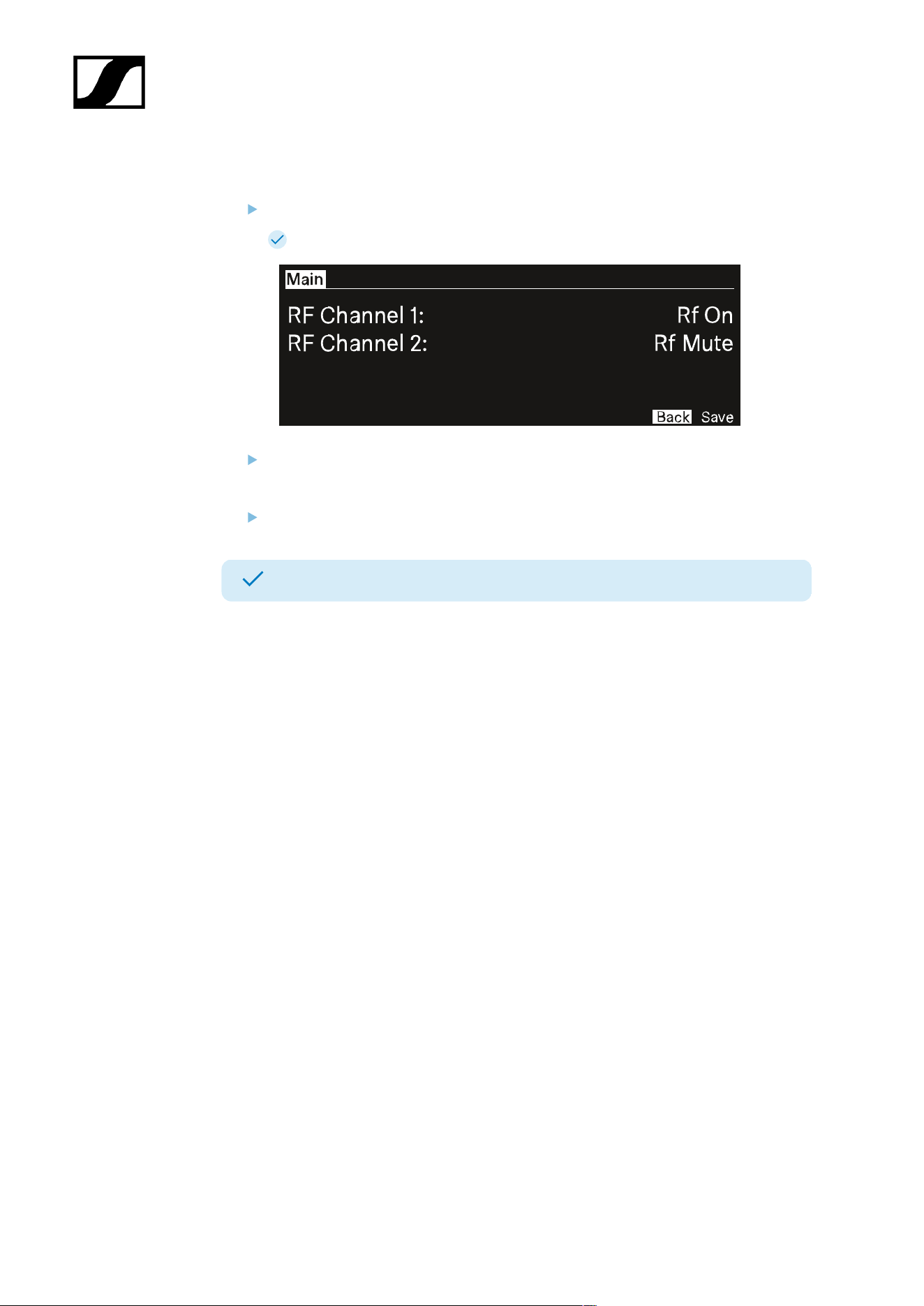
Press the jog-dial.
The RF Status menu opens.
Rotate and press the jog-dial to change the settings.
You can select between Rf on and Rf Mute.
Confirm by selecting Save or discard the changes by selecting Back.
The RF Channels have been muted/unmuted.
64
| 4 - Instruction manual
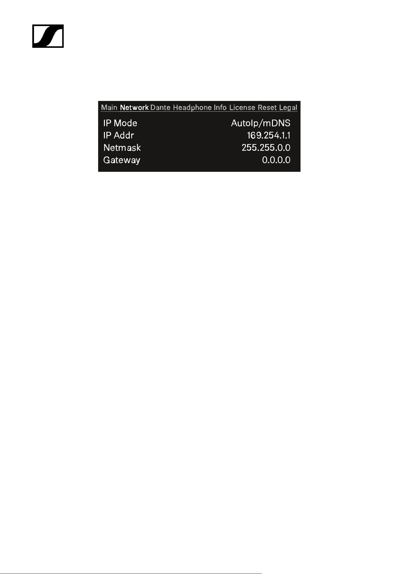
Network
In this menu item, you can configure the settings for the network connection.
You can make the following settings here:
IP Mode
• Manual
• You can change the IP Address, the Netmask and the Gateway.
• Manual/mDNS
• You can change the IP Address, the Netmask and the Gateway.
• AutoIp
• You can not change the IP Address, the Netmask and the Gateway.
• AutoIp/mDNS
• You can not change the IP Address, the Netmask and the Gateway.
65
| 4 - Instruction manual
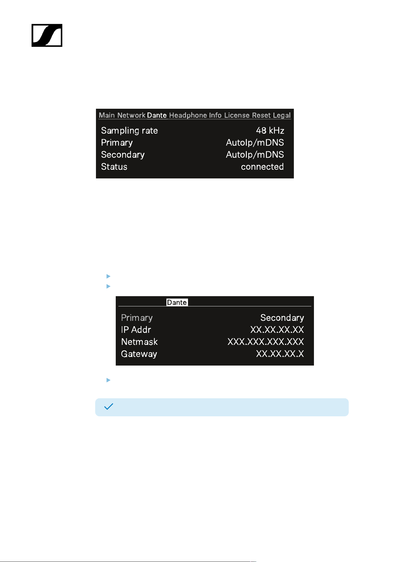
Dante
In this menu item, you can view information about the two Dante® connections.
The following information are displayed:
• Sampling rate
• IP mode for Primary
• IP mode for Secondary
• Status
To display a Dante® connection:
Press the jog-dial to change the Dante® connection.
Rotate the jog-dial to change between Primary and Secondary.
Press the jog-dial to enter the setting.
The selected Dante® connection is displayed.
66
| 4 - Instruction manual
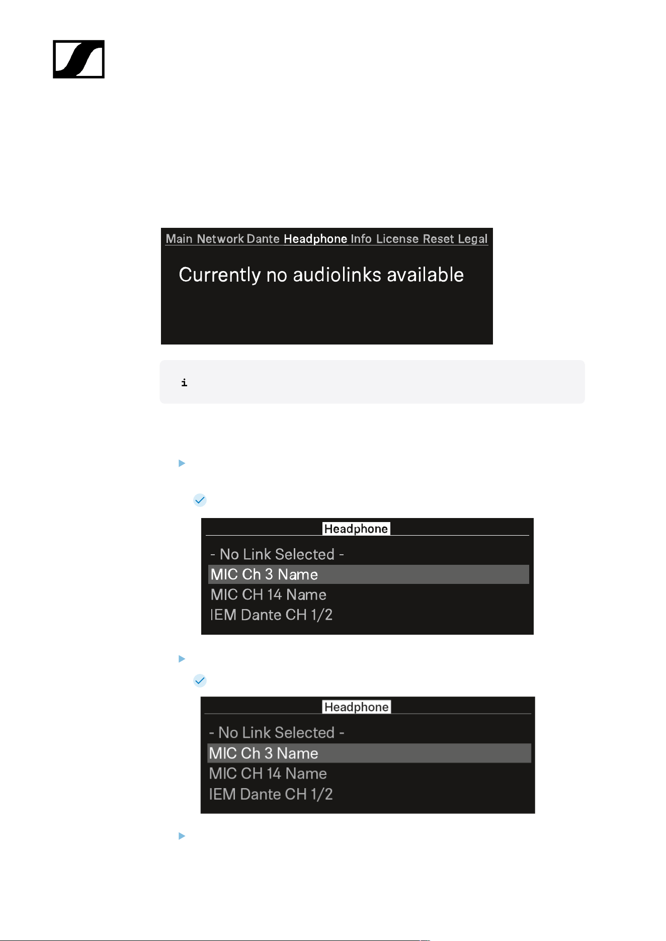
Headphone
In this menu item, you can select the headphone output.
You have to set up audio links via Spectera WebUI for the mobile devices.
If no audio link is set this note will appear:
First you have to set up audio links in Spectera WebUI.
To select an audio link:
Press the jog-dial to enter the headphone menu.
Each audio output will be shown independent.
The created audio links appear.
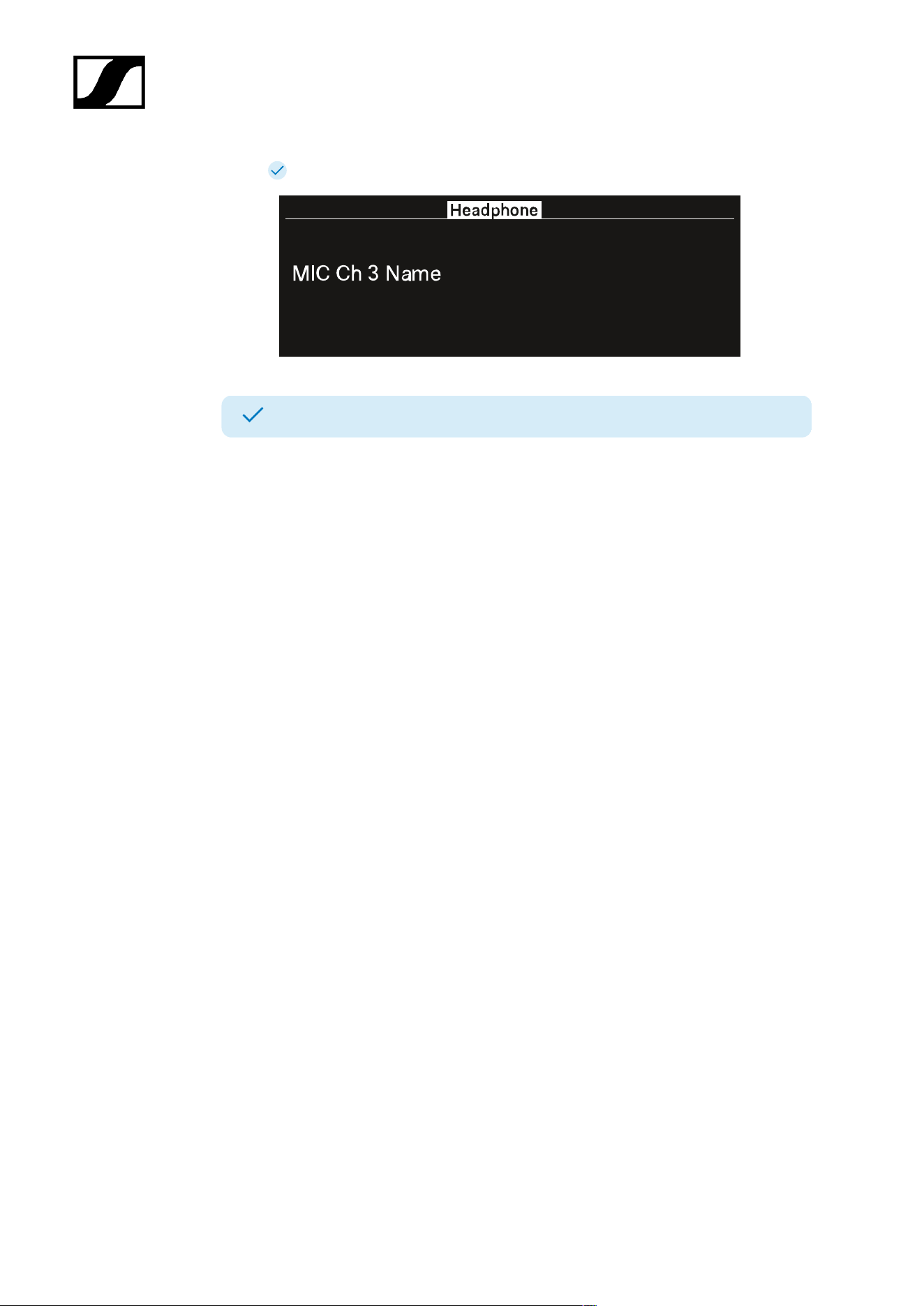
Turn the jog-dial to select the wanted audio link.
The name of the selected link pulses two times.
Press the jog-dial to return to the main menu.
67
| 4 - Instruction manual
The selected link appears.
You can now listen to the selected audio link.
68
| 4 - Instruction manual
Info
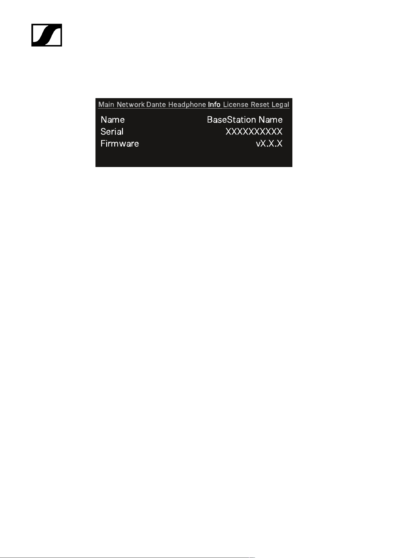
In this menu item, general information can be shown here.
Name: The name of the Base Station.
Serial: The serial number of the Base Station.
Firmware: The installed firmware version.
69
| 4 - Instruction manual
License
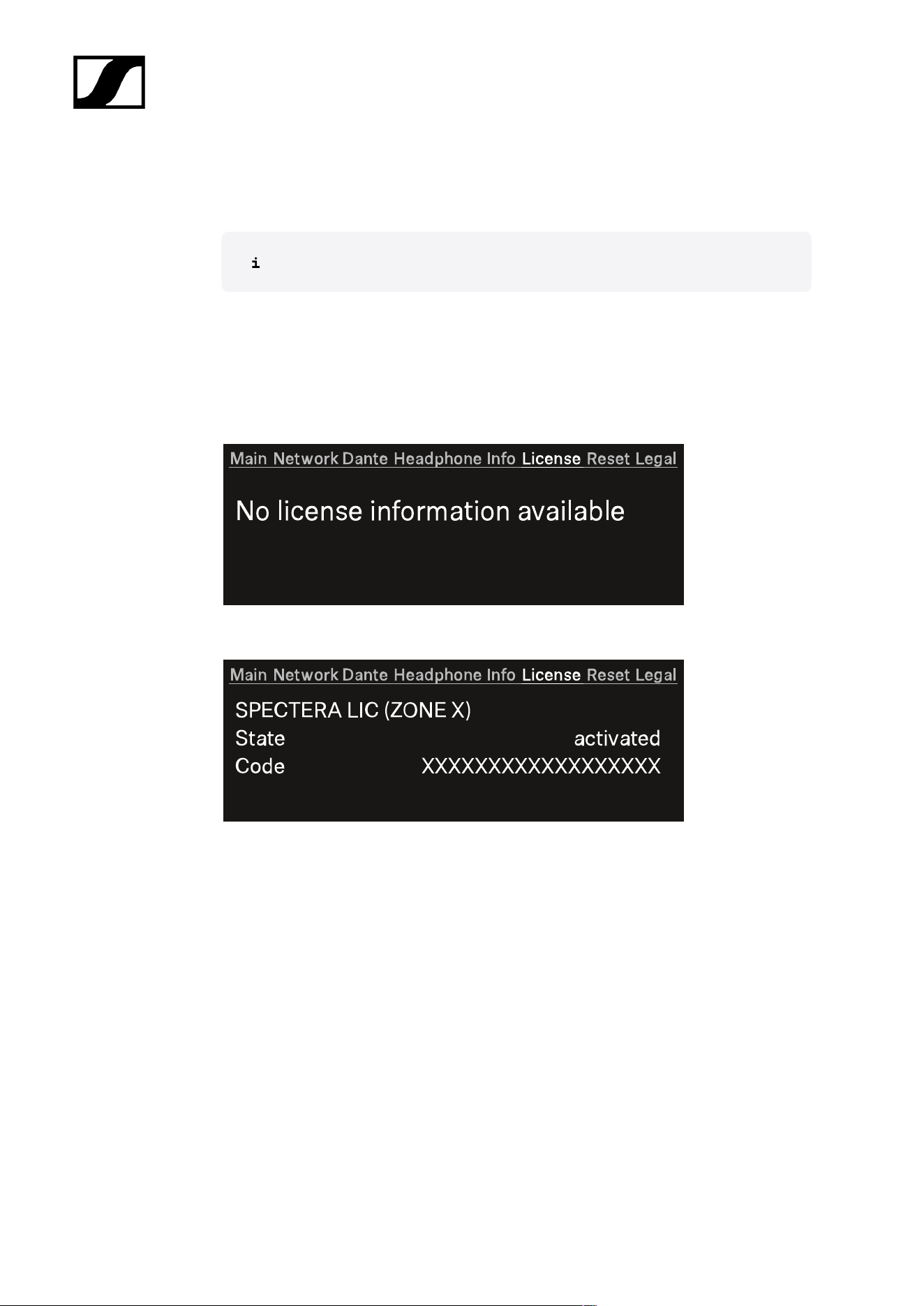
In this menu item, information about the license can be shown here.
A license has to be activated, otherwise you cannot use the Base Station.
You can activate a license via Spectera WebUI.
Only one license per Base Station is possible.
The license specifies the country-specific frequency ranges and the RF power.
No license is activated:
A license is activated
Name of the purchased license:
• Spectera LIC (ZONE 01)
• ...
• Spectera LIC (ZONE XX)
State: Status of the license.
• activated
• unknown
Code:
• The activated license number has 18 digits.
• n/a
70
| 4 - Instruction manual
Reset
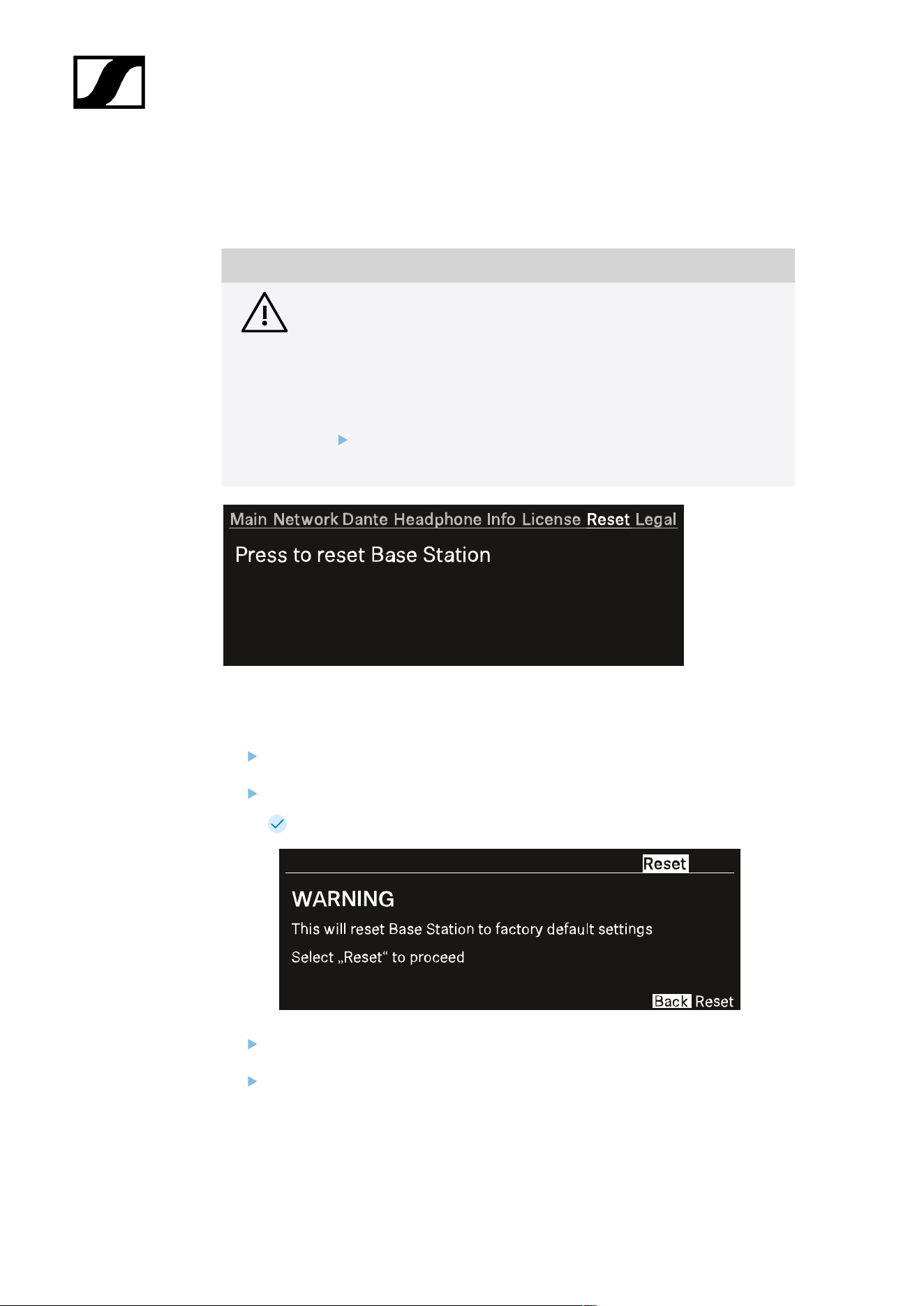
In this menu item, you can reset the Base Station to its factory settings.
NOTICE
Data loss during the factory reset
All audio devices will be unpaired and all audio routes will be deleted.
All settings (including the device password) are reset to the default
values. The license remains activated.
After the reset, the device is restarted automatically.
Do not reset the Base Station during an active live audio
transmission.
To reset the Base Station to its factory default settings using the device:
On the Base Station, rotate the jog-dial and navigate to the menu Reset.
Press the jog-dial to enter the menu.
A warning will appear.
Rotate the jog-dial to Reset.
Press the jog-dial again.
71

| 4 - Instruction manual
The Base Station will be set back to factory settings and reboot.
After rebooting, check the IP address as it may have changed.
The Base Station has been reset to its factory default settings.
72
| 4 - Instruction manual
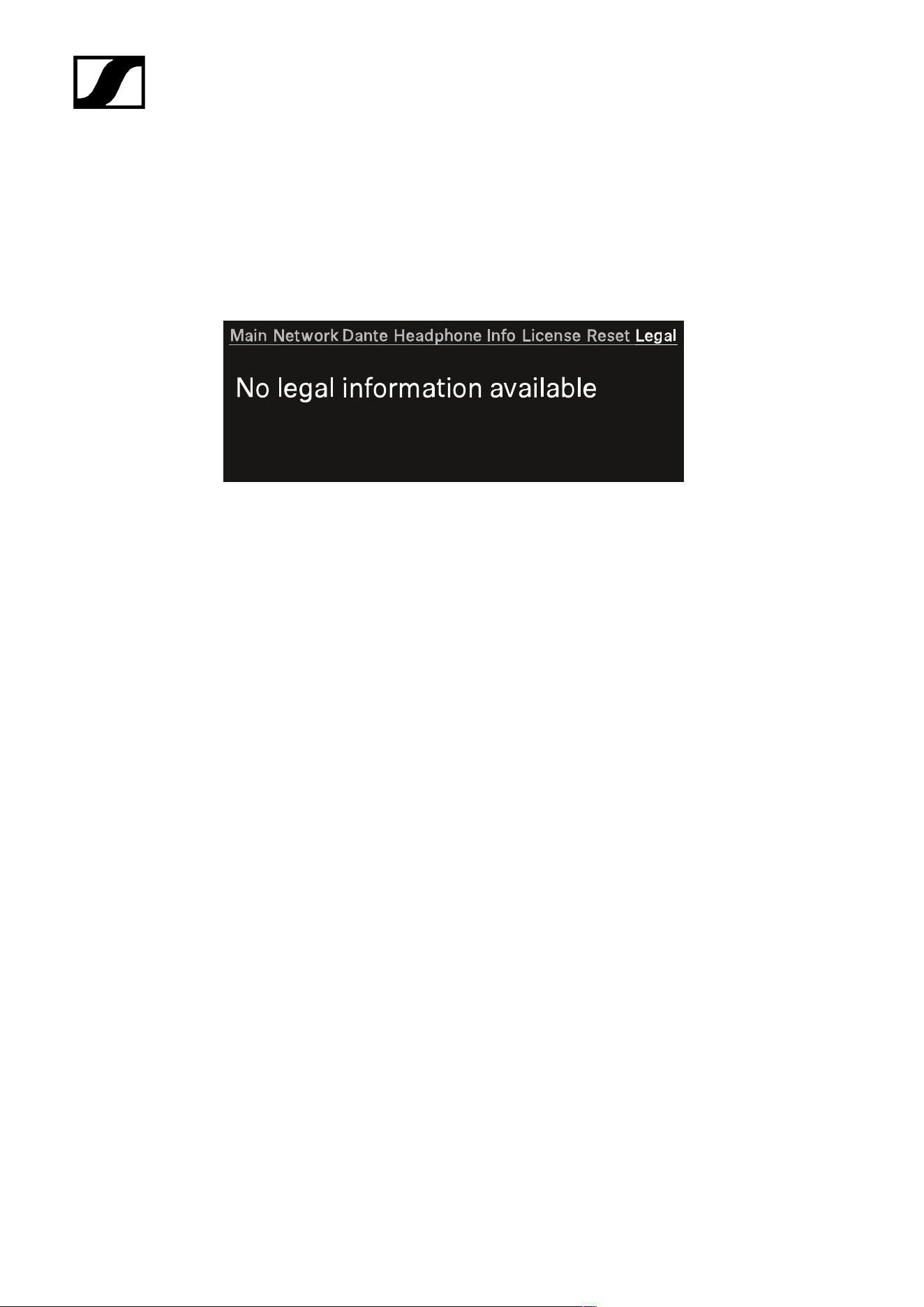
Legal
In this menu item, legal information can be shown.
Legal information about the Base Station and connected antennas are displayed depending
on the activated license.
If no label are available, the display shows:
73
| 4 - Instruction manual
Updating the Base Station
You can update the firmware of the Base Station via Spectera WebUI.
All Spectera devices must use the same firmware. The Base Station determines the firmware
version.
Please note that firmware versions are not backward compatible.
NOTICE
Data loss during firmware update
The audio transmission is interrupted during the firmware update of the
Base Station, the antenna or the mobile device.
After the firmware update, the device is restarted automatically.
Do not update the firmware during an active live audio
transmission.
To update the firmware:
If you want to update the Base Station via Spectera WebUI, follow the steps described
here: Updating the firmware (Base Station).
The LED is flashing green and red during the update.
When the update is installed, the Base Station restarts.
The update will be installed on the connected antennas automatically.
The firmware has been updated.
The new firmware is distributed to the other devices via the Base Station.
74
| 4 - Instruction manual
WebUI
Detailed description of the WebUI navigation and configuration.
Please navigate to the desired chapters by clicking on the related information.
Getting started
Start your basic configuration with the recommended steps.
When setting up the WebUI for the first time, we recommend following these first steps to
successfully configure the system from the outset:
• Identifying Base Station via IP
• Claiming single device (WebUI)
• Activating a license (WebUI)
• Enabling/disabling data collection
• Enabling solo control
• Configuring RF channels
• Assigning an antenna to an RF channel
• Scanning the RF frequency
• Pairing/unpairing mobile devices
• Selecting the default audio input/output source
• Selecting audio link mode (Mic/Line)
• Selecting audio link mode (IEM)
• Assigning an RF channel
• Selecting the Mic/Line input
Operational data is collected to continuously improve the stability and
functionality of Spectera. The data is pseudonymized to ensure there is no
direct personal reference. Tracking can be disabled in the settings (see chapter
Enabling/disabling data collection).
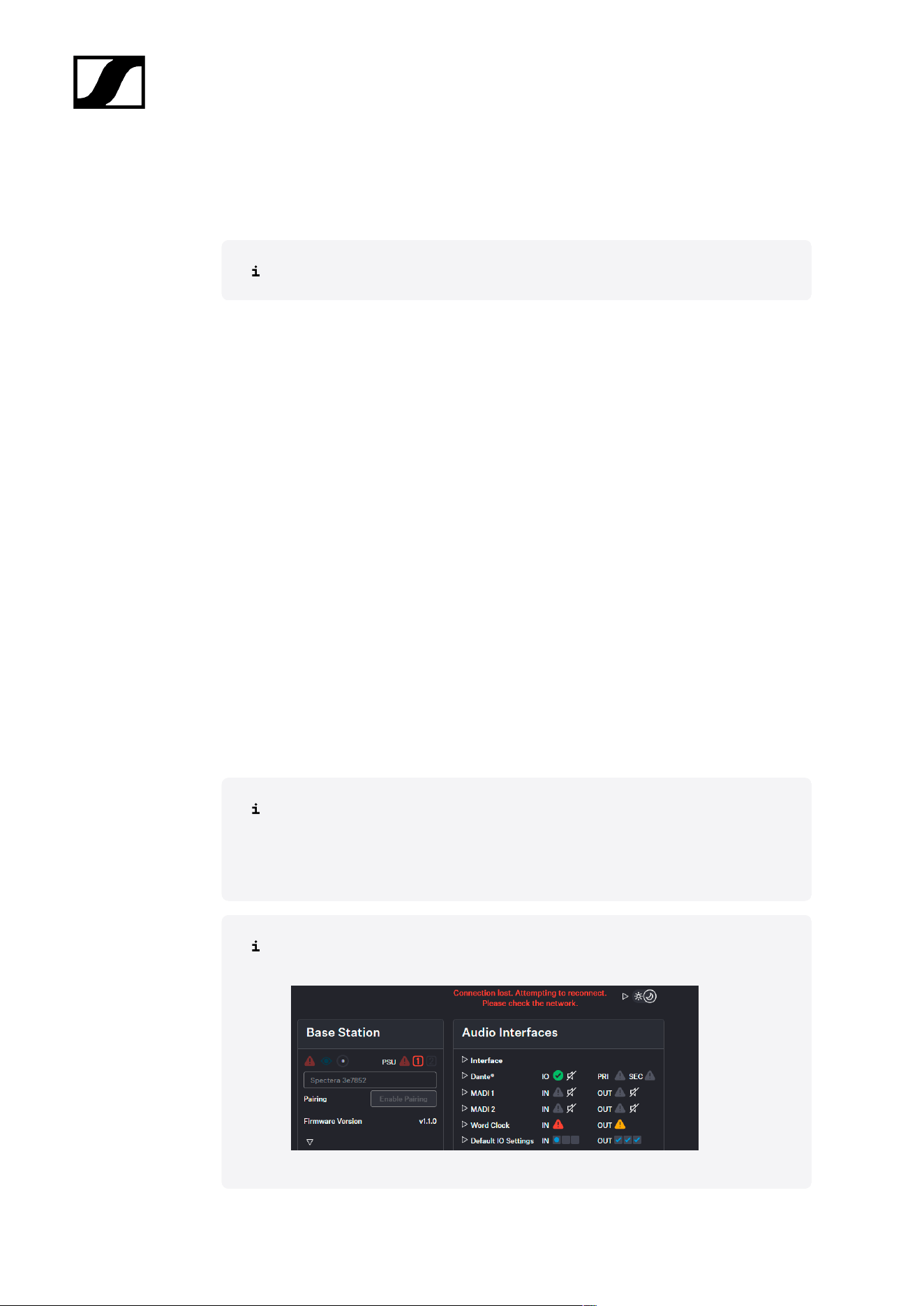
If the connection to the device is lost (no power supply or no network connection),
the live status will be displayed based on an error message.
75
| 4 - Instruction manual
Identifying Base Station via IP
In order to add a Base Station, its IP address is required.
You can read the IP address on the display of the device.
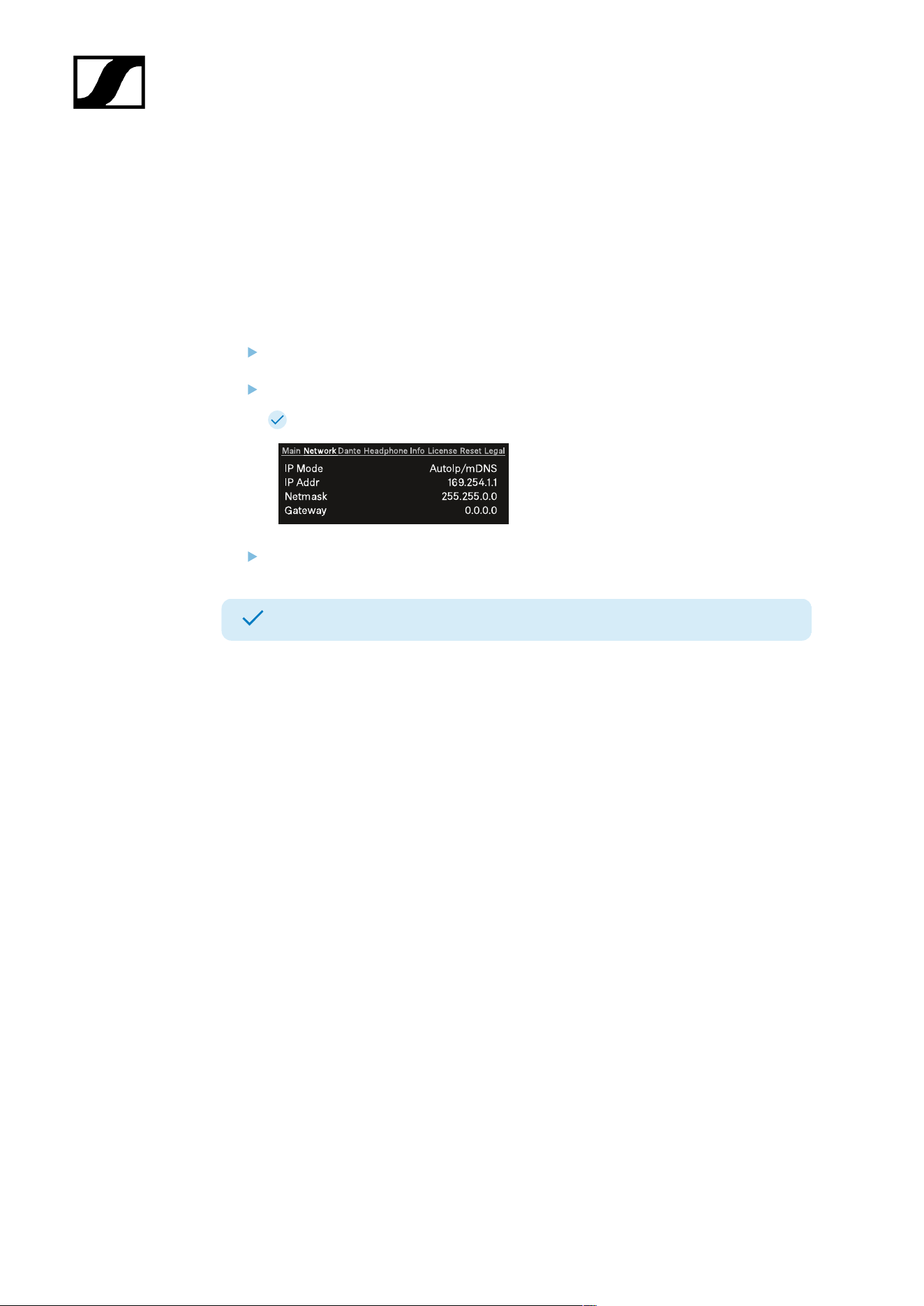
To identify the IP of your Base Station:
On the Base Station, rotate the jog-dial and navigate to the menu Network.
Press the jog-dial to enter the menu.
The network data will be displayed.
Note the displayed IP of your device.
The IP address of your Base Station has been identified.
76
| 4 - Instruction manual
Claiming single device (WebUI)
Instructions for claiming a single device in Spectera WebUI.
To claim your Base Station:
Enter the following URL into your browser: https://deviceIP/specterawebui/
index.html .
Since the certificate is unknown to your browser, a security warning is
displayed the first time you run the application. The security warning
depends on the browser you are using.
Depending on your browser, click on Advanced and then on:
• Continue to localhost (unsafe) (Microsoft Edge)
• Proceed to localhost (unsafe) (Google Chrome)
• Accept the Risk and Continue (Firefox)
• or similar (other browsers).
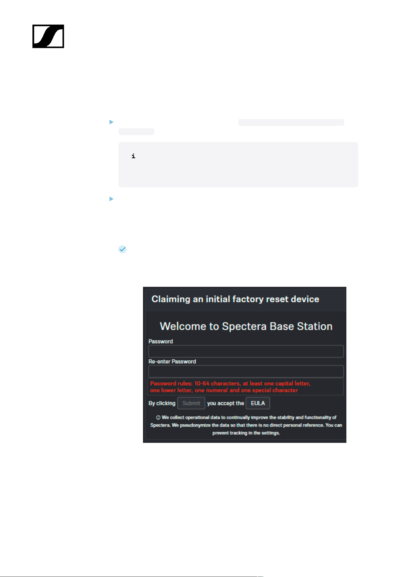
The WebUI displays the following options depending on the state of the device:
•If the device is in a factory default state and the original password is still
assigned, it will be automatically detected and applied. Next, a new
password has to be set:
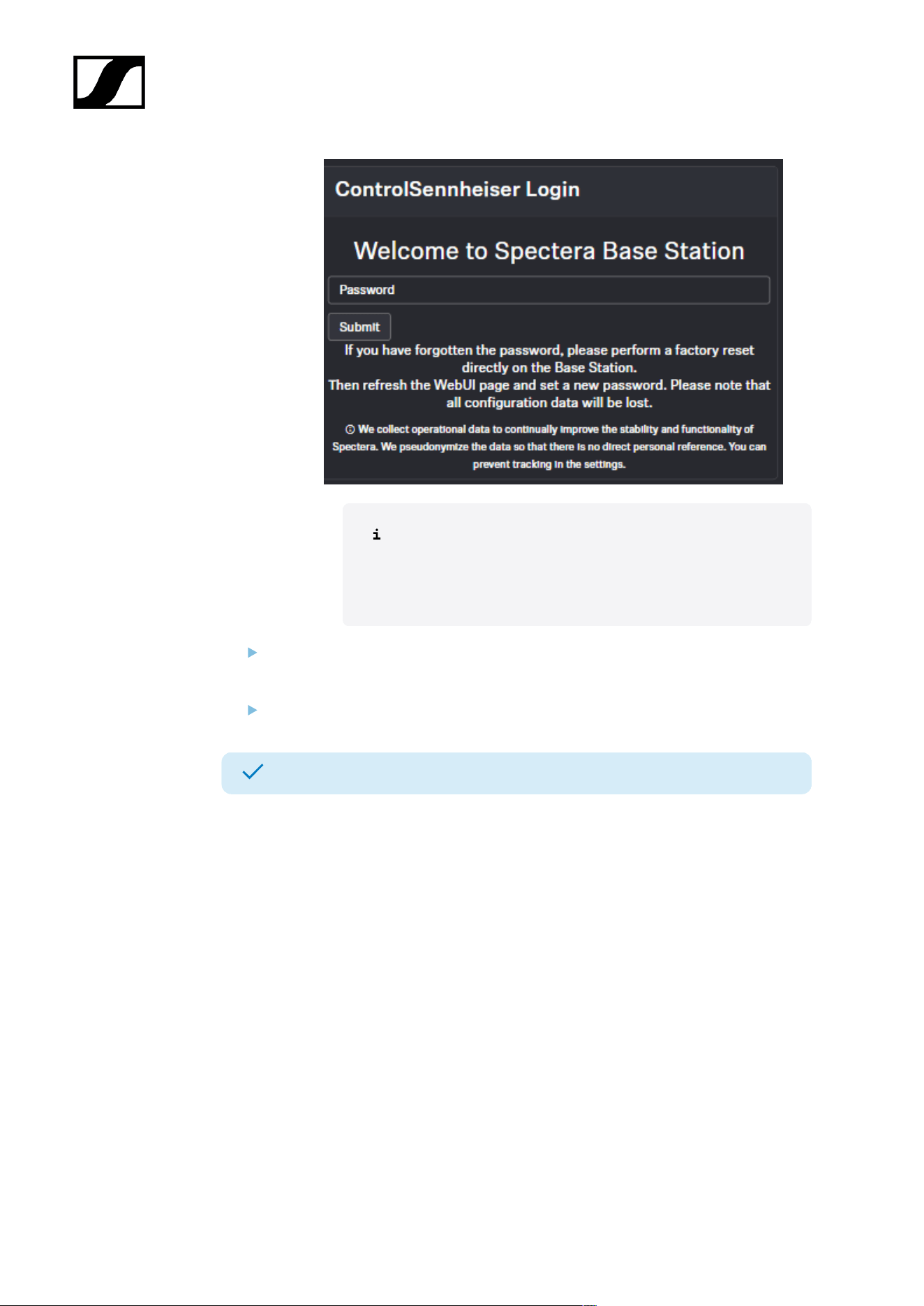
•If the device was previously claimed by another Sennheiser LinkDesk or
Spectera WebUI instance, the previously set password must be entered:
77
| 4 - Instruction manual
If you cannot remember the previously set password, please
perform a factory reset of the device. After the reset, the
default password for Spectera will be automatically applied
by the software.
Set a new device password (if you are logging in for the first time) or enter the
password you have already assigned for authentication (if you have already logged in).
Click on Submit.
Your Base Station has been claimed successfully.
78
| 4 - Instruction manual
Activating a license (WebUI)
Under Entitlement, you can enter and activate the current license for the frequency
spectrum.
The purchased license (included in the product) is only valid for the region for
which the product was designed and approved. The license may not be used in
other regions.
NOTICE
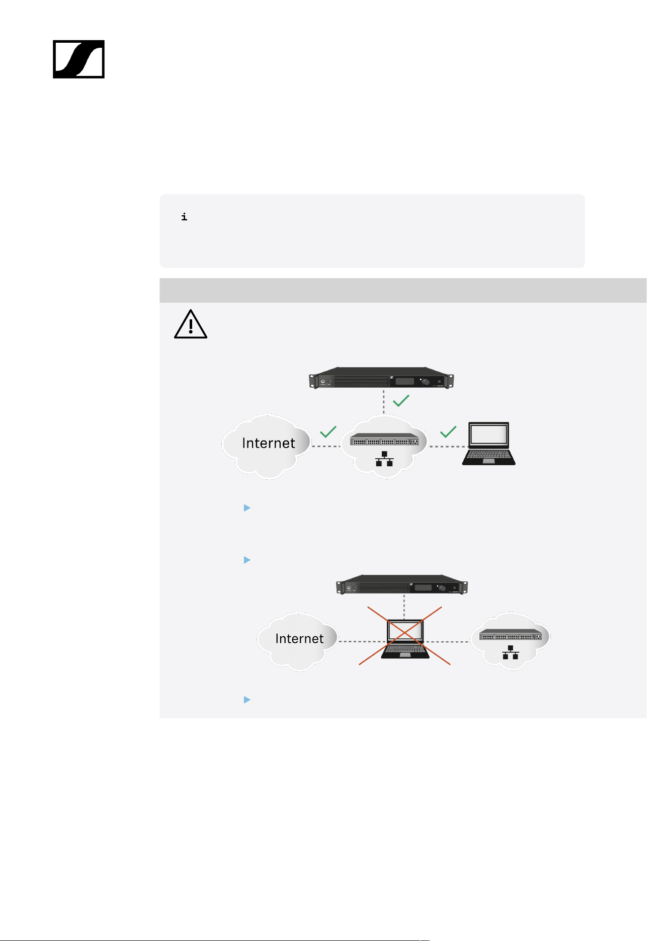
License activation requires a direct Internet connection to the device
In order to activate the Base Station using the 18-digit license code, a direct Internet
connection is required.
Please connect your Base Station directly to a network with Internet access via
a switch or router. For more information, refer to the chapter Connecting to a
network.
Direct connections via laptop etc. are not supported for activation!
The Internet is only required once for activation.
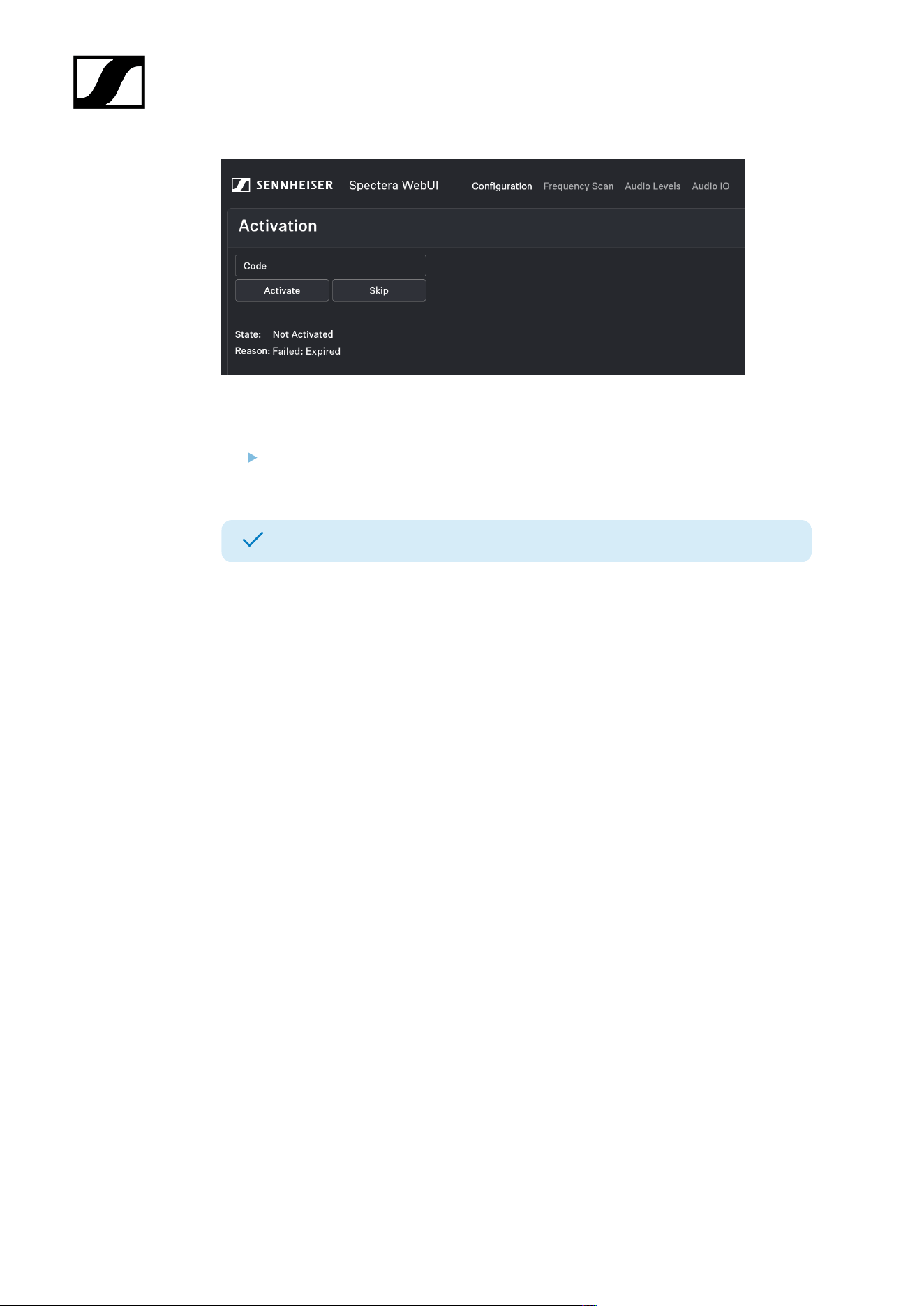
When you start the device for the first time, your license key is requested.
79
| 4 - Instruction manual
To activate the license:
Enter the acquired license and click on Activate or on Skip to proceed with activation
later.
Your license has been activated.
80
| 4 - Instruction manual
Enabling/disabling data collection
Spectera collects operational data to enhance stability and functionality.
The data is pseudonymized to ensure there is no direct personal reference.
To enable/disable data collection:
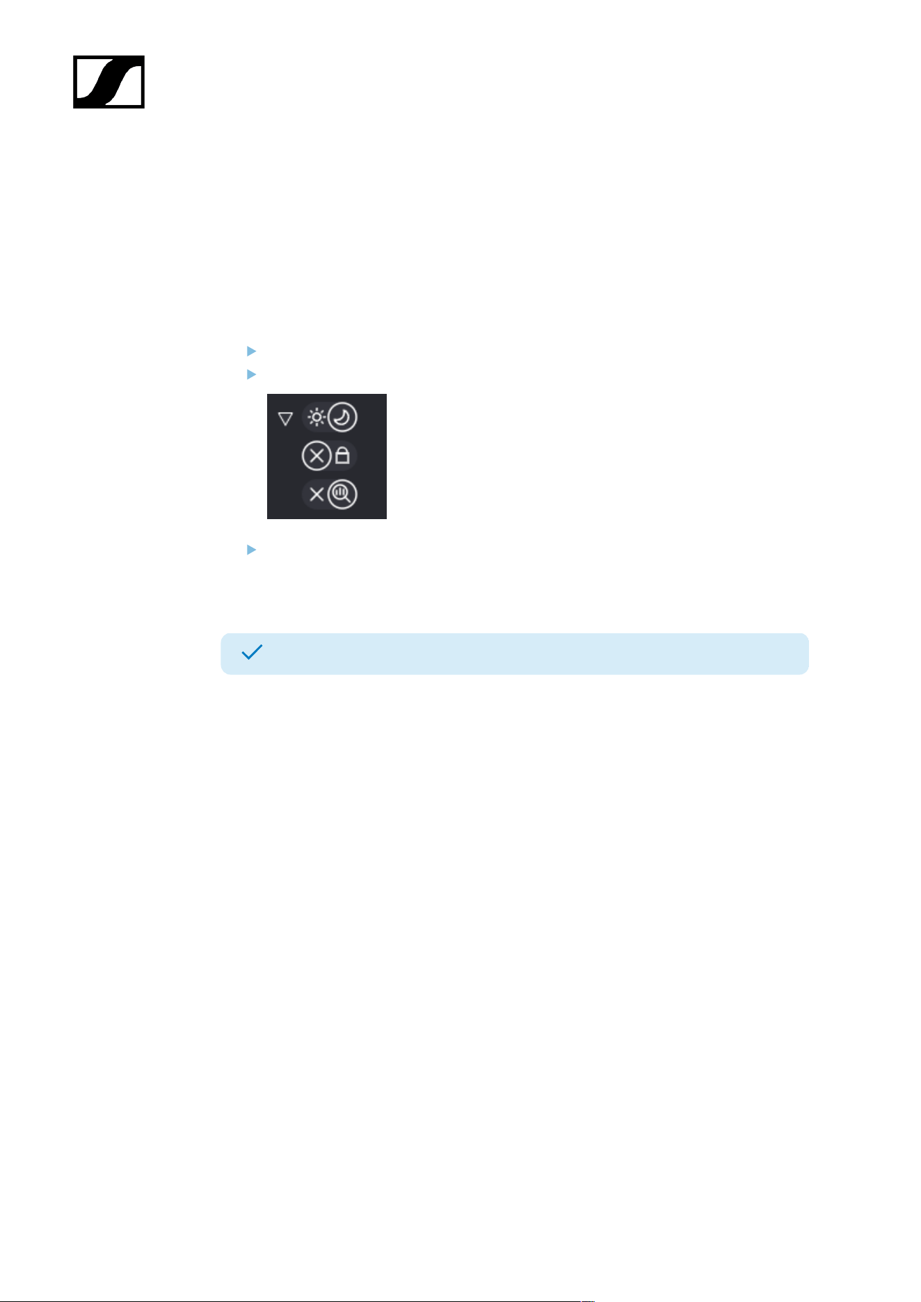
On the start page, navigate to the top navigation at the top right.
Click on the triangle to expand the settings.
Click on:
• the X to stop data collection
• the magnifying glass to enable data collection.
Data collection has been enabled/disabled.
81
| 4 - Instruction manual
Configuring RF channels
Here you can find out how to configure the RF channel correctly from the outset.
The current local permissions are displayed when the frequency is selected.
To configure an RF channel:
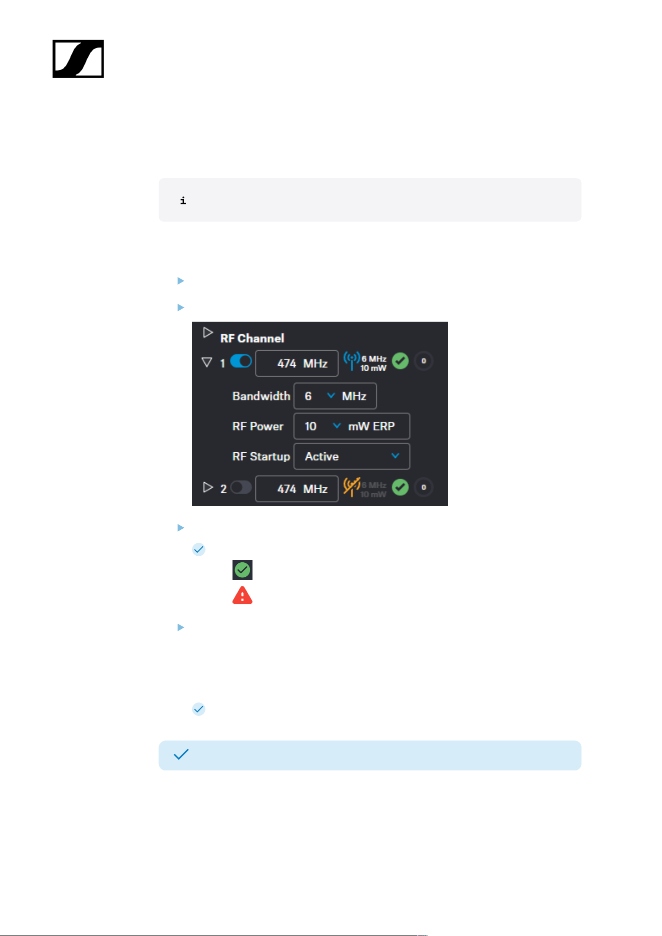
In the top bar, navigate to Configuration > RF Configuration.
For channel RF1, enter the frequency under 1 and confirm with ENTER.
Next, select the Bandwidth and the RF Power for your location.
The applicability of your settings is indicated by an icon:
• green: applicable
• red: not applicable
Under RF Startup, select the mute option for the configured RF channel:
• Active
• Muted
• Last state = When switching on or leaving standby mode, the last used RF
state is restored
The RF Channel has been assigned to the operating antenna.
The RF Channel has been configured.
82
| 4 - Instruction manual
Assigning an antenna to an RF channel
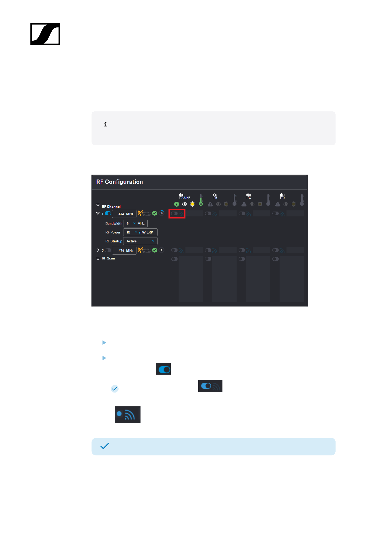
You can choose between up to four connected antennas to assign them to your two
possible RF channels.
For additional reliability in terms of redundancy or to extend your range, you can
assign up to four antennas per channel and use them simultaneously.
The antennas can be assigned and unassigned, e.g. to perform an RF scan or to switch
between the configured RF channels.
To assign an antenna for an RF channel:
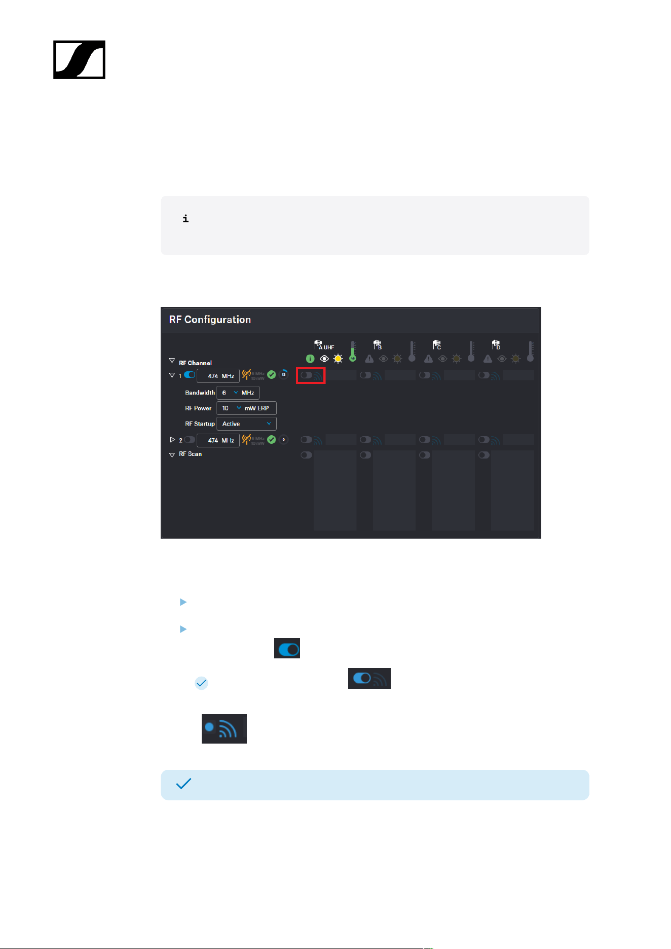
In the top bar, navigate to Configuration > RF Configuration.
In your RF channel row, click on the toggle switch next to the utilization and
interference icon .
The toggle switch turns blue . The antenna has been assigned to the RF
channel and any potential interference is indicated by the icon.
The antenna has been assigned to a specific RF channel.
83
| 4 - Instruction manual
Scanning the RF frequency
You can run a frequency scan to check the current frequency situation in your surrounding
area.
The frequency scan provides an overview of the frequency situation in your location. You can
save the antenna configuration as a .csv info file. This file can be used as a backup file to
recapitulate your settings or as local frequency information for your specific environment.
You can scan the frequencies of all antennas connected to the Base Station.
The scan can be initiated:
• via the RF configuration tab to see a small extract without any details or
• via the Frequency Scan tab for a detailed overview of the frequency situation.
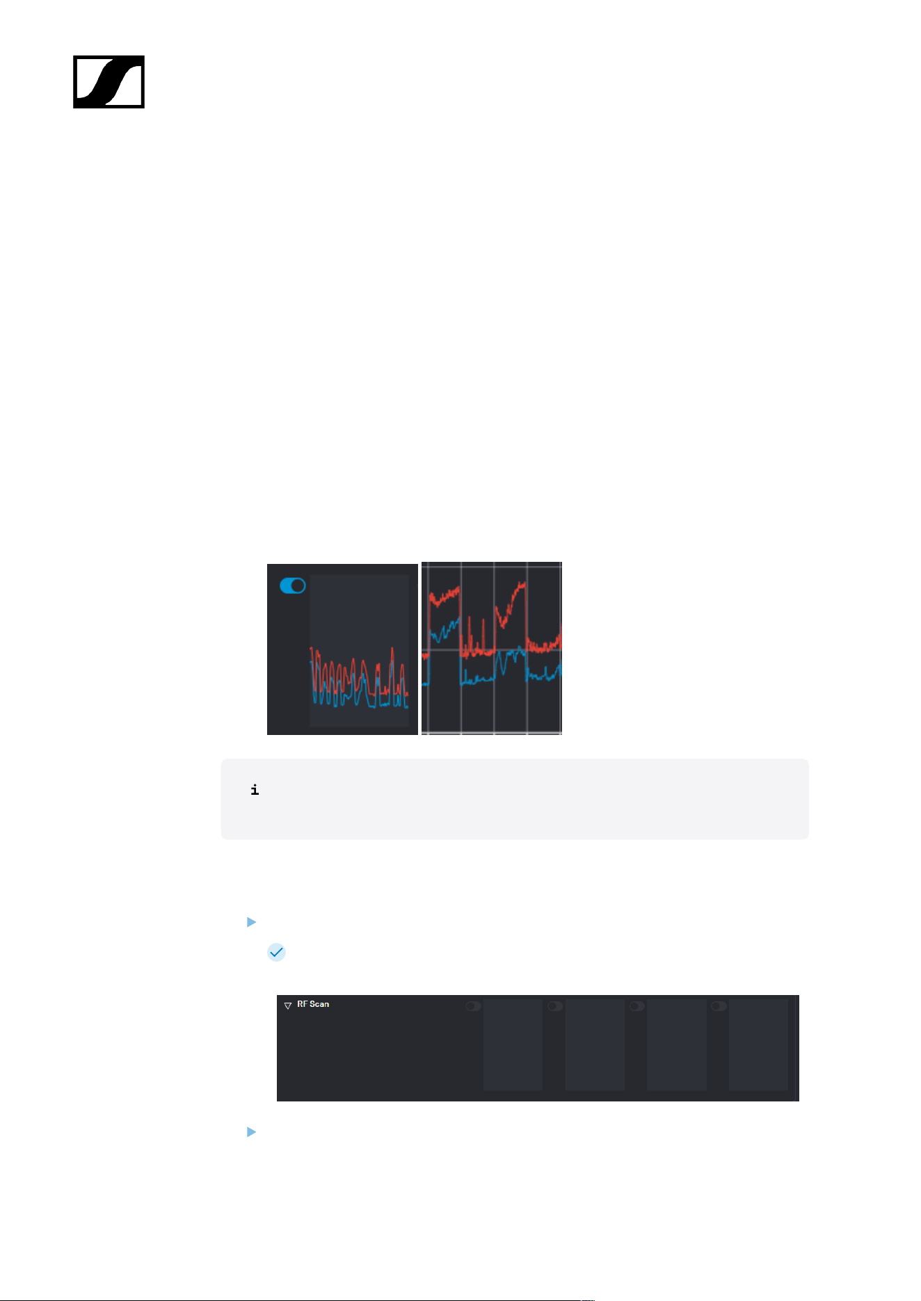
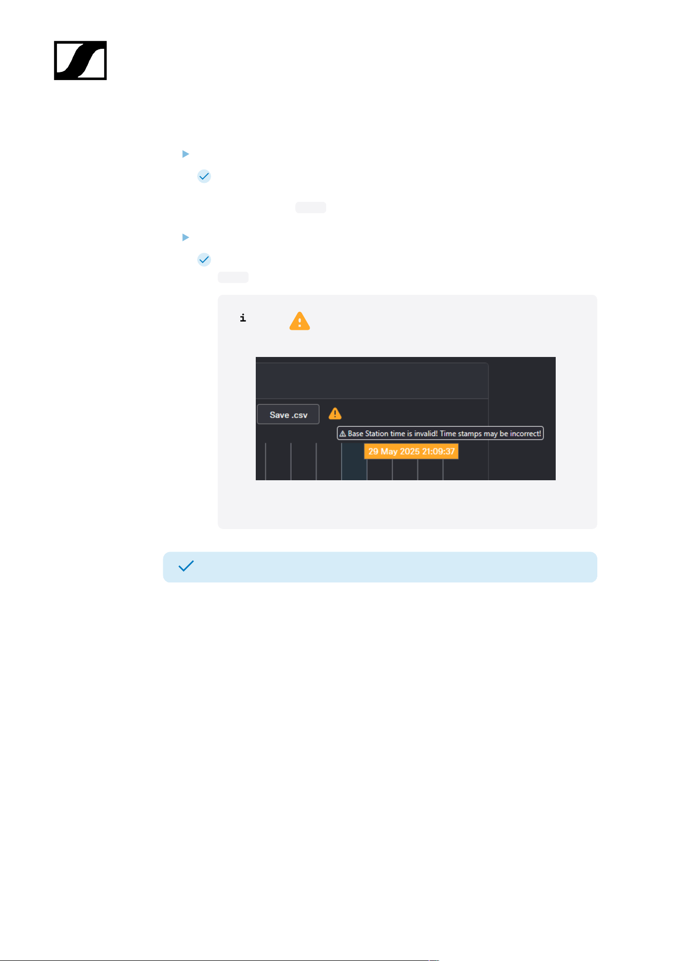
The scan results will be displayed in two different curves:
• Peak (red) = Maximum value
• RMS (blue) = Average power or strength
Please note that the antenna must not be assigned to an RF channel before
scanning (see Assigning an antenna to an RF channel).
To scan the RF frequency via the RF configuration tab:
In the top bar, navigate to Configuration > RF Configuration.
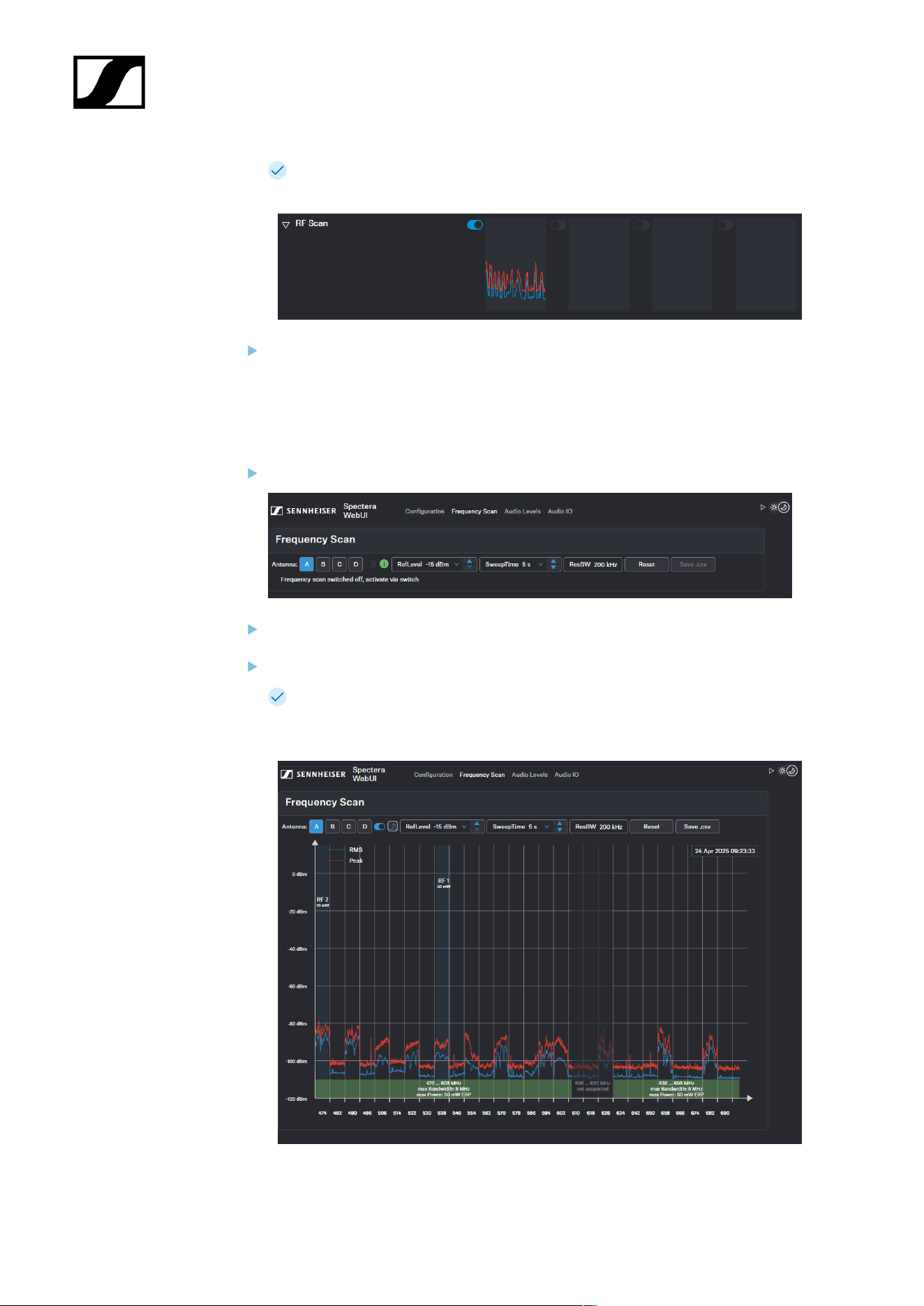
Under the RF Scan drop-down menu, there are four toggle switches that enable
and disable the scan function for each connected antenna.
Click on the toggle switch of the antenna to be scanned in order to start an immediate
scan.
84
| 4 - Instruction manual
The square is highlighted with a blue dot and the scan result is displayed in a
small frequency curve after approx. 5 seconds.
In order to view the results,
• click on the small frequency icon or
• navigate to Frequency Scan in the top bar.
To scan the RF frequency via the Frequency Scan tab:
In the top bar, navigate to the tab Frequency Scan.
Select your antenna to be scanned and adjust your desired settings.
Switch on the toggle to start the scan.
The frequency scan is started and the result is displayed in a detailed frequency
diagram. Supported frequency ranges are shown in green and unsupported
ranges in gray.
85
| 4 - Instruction manual
To reset a scan:
Click on Reset.
The current scan will be reset.
To save the scan results as .csv :
Click on Save.csv.
The antenna configuration has been downloaded locally to your computer as a
.csv file.
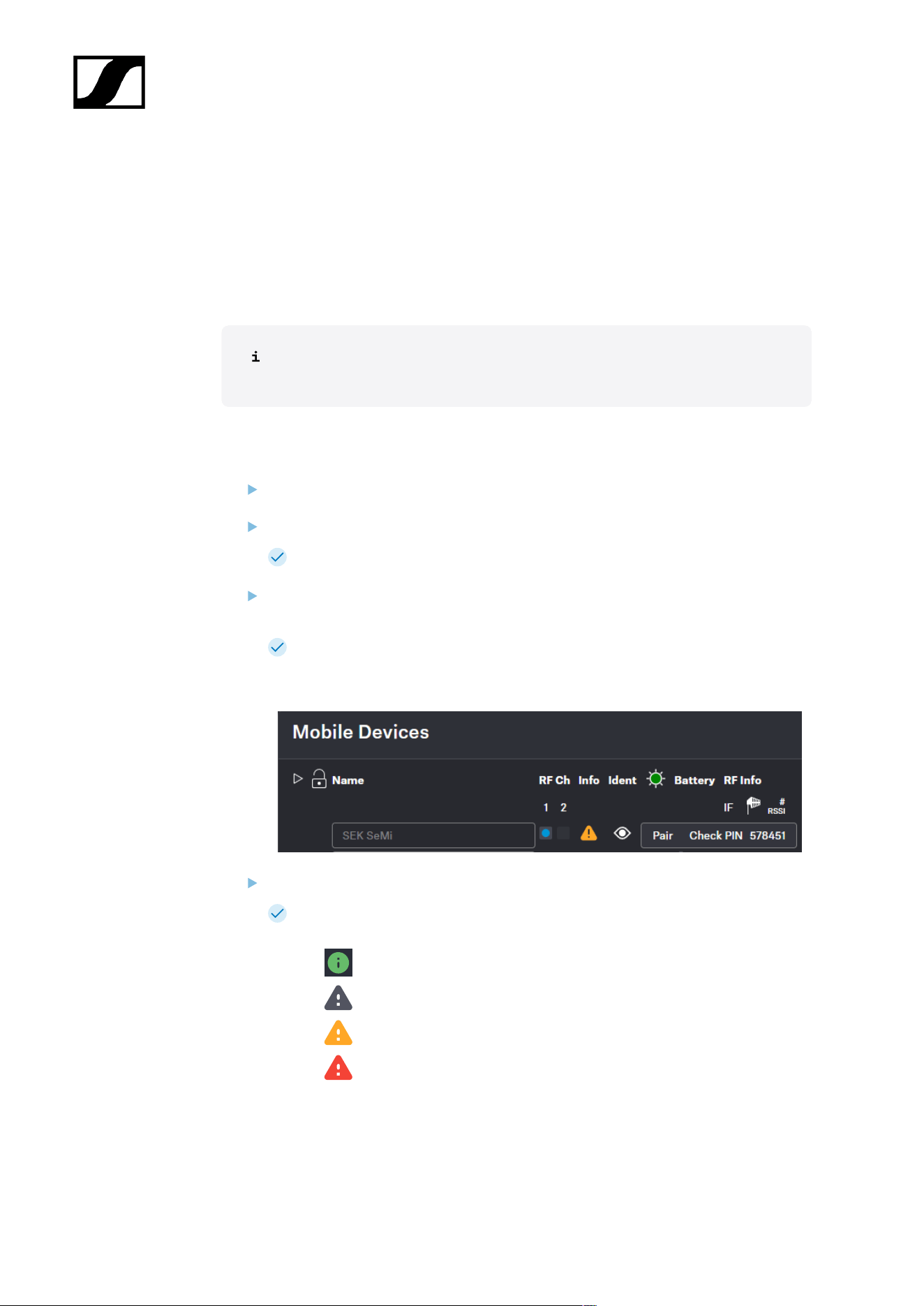
If a appears after Save.csv, the time on the Base Station is
invalid.
Connect the Base Station to the Internet to get the correct time.
The frequency of your connected antenna has been scanned.
86
| 4 - Instruction manual
Pairing/unpairing mobile devices
In the WebUI, you can pair up to 128 mobile devices to a Base Station within one RF
channel.
Mobile devices can only be paired and operated with one Base Station at a time. If a mobile
device is to be used with another Base Station, it must first be paired again.
Please unmute at least one RF channel before pairing if this was not done
automatically.
To pair a mobile device:
In the top bar, navigate to Configuration > Base Station.
Click on Enable Pairing.
The Base Station starts the pairing process for 300 seconds.
Switch on your mobile device and activate Pairing Mode if it has not been activated
automatically (Switching the SEK on and off/Switching the SKM on and off).
After a few seconds, the available mobile devices are displayed in the list below
under Mobile Devices. A verification PIN is displayed on the mobile device and in
the WebUI.
Verify the PIN on the mobile device and click on Pair.
The mobile device has been paired successfully. The device state color changes
to:
• green (successfully paired)
• gray (assigned RF channel not on air)
• yellow (firmware mismatch) or
• red (unconnected, no RF channel selected, not available)
87

| 4 - Instruction manual
To unpair a mobile device:
To unpair a paired device, the audio links must first be deactivated.
In the top bar, navigate to Configuration > Mobile Devices.
Click on the button Unpair > Confirm in the line of the mobile device to be unpaired.
The mobile device has been successfully unpaired.
The mobile devices have been successfully paired/unpaired.
88
| 4 - Instruction manual
Selecting the default audio input/output source
You can select the default source for the audio input and output of your audio interface.
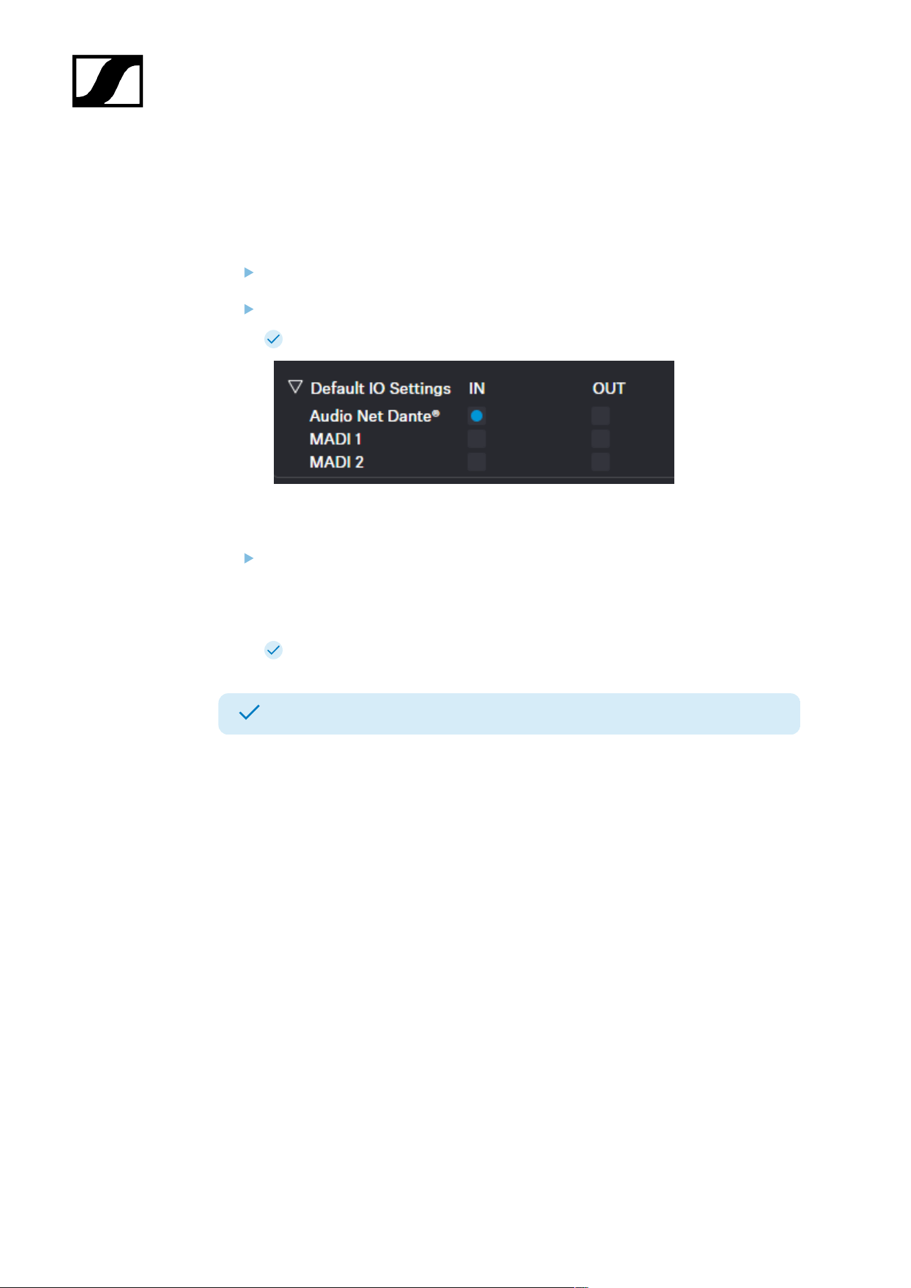
To select the default input interface:
In the top bar, navigate to Configuration RF > Audio Interfaces.
Select the input interface under Default IO Settings.
The default input interface has been selected.
To select the clock source output:
Select the desired setting for the clock source under:
• MADI 1
• MADI 2
• Word Clock BNC
The clock source output has been selected.
The audio interfaces have been selected.
89
| 4 - Instruction manual
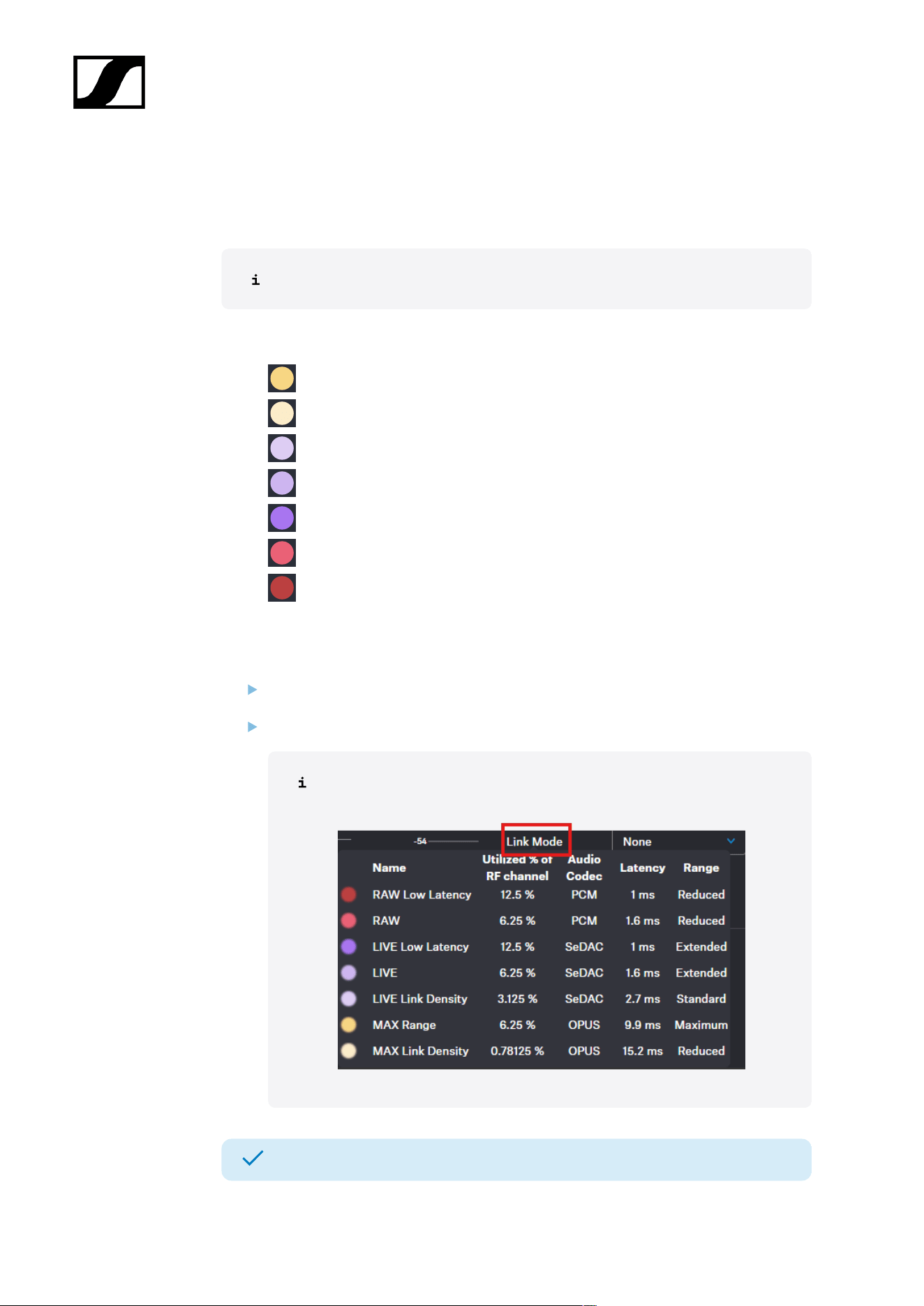
Selecting audio link mode (Mic/Line)
You can select the audio mode for your Mic/Line link.
Please note that the bandwidth utilization varies depending on the link mode.
The following modes are available:
• Max Range
• Max Link Density
• Live Link Density
• LIVE
• Live Low Latency
• RAW
• RAW Live Low Latency
To select the audio mode:
In the top bar, navigate to Configuration > Mobile Devices > Mic Settings.
Select the audio mode from the drop-down list Link Mode.
Hover your mouse over the word Link Mode to display a tabular listing
of possible modes.
The audio mode has been selected.
90
| 4 - Instruction manual
Selecting audio link mode (IEM)
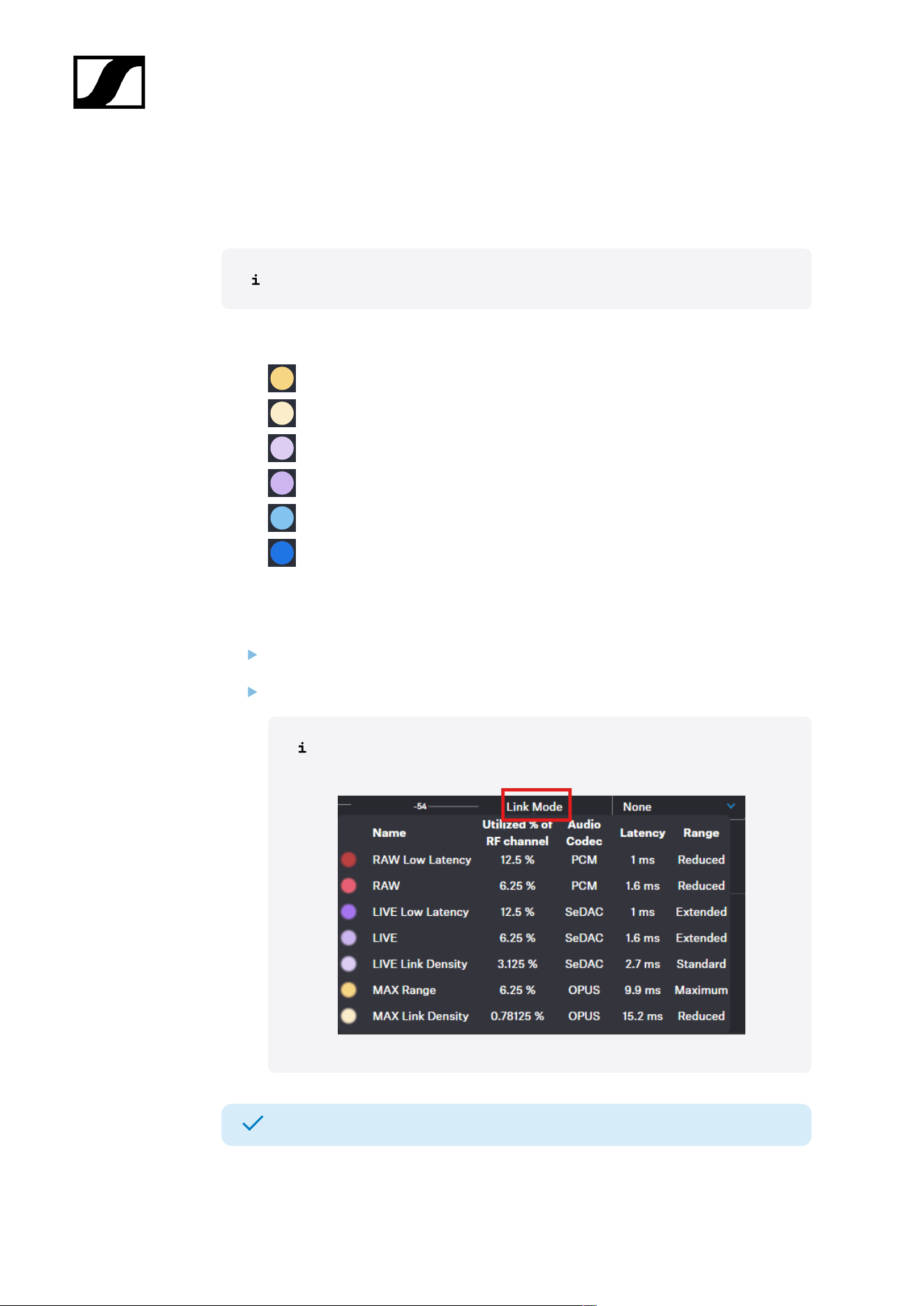
You can select the audio mode for your IEM link.
Please note that the bandwidth utilization varies depending on the link mode.
The following modes are available:
• Max Range
• Max Link Density
• Live Link Density Range
• Live Link Density Range
• Live Low Latency
• Live Ultra Low Latency
To select the audio mode:
In the top bar, navigate to Configuration > Mobile Devices > IEM Settings.
Select the audio mode from the drop-down list Link Mode.
Hover your mouse over the word Link Mode to display a tabular listing
of possible modes.
The audio mode has been selected.
91
| 4 - Instruction manual
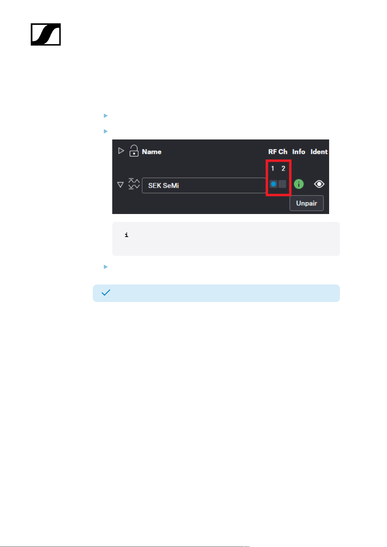
Assigning an RF channel
You can assign a configured RF channel to your mobile device.
To assign the RF channel:
In the top bar, navigate to Configuration > Mobile Devices.
Select your configured channel under RF Ch.
To change the RF channel, you must first deactivate the audio Link Mode
and the audio Channels.
Enable the toggle switch of the configured RF channel.
The RF channel has been assigned to your mobile device.
92
| 4 - Instruction manual
Selecting the Mic/Line input
You can select the audio input as the signal source for your Mic/Line link.
For a smooth system configuration, we recommend first selecting the link modes
and afterwards assigning the channels:
• Selecting audio link mode (Mic/Line)
• Selecting audio link mode (IEM)
• Adding/removing an audio channel (Mic/Line)
• Selecting an audio channel (IEM link)
• Selecting the IEM audio interface
You can route audio links to several channels. Routing can be performed easily
via the routing matrix (see Audio inputs and outputs).
The following input signals are available:
• Auto (unknown)
• Mic
• Line
The automatic mic/line detection is based on power consumption and
is optimized for use with Sennheiser microphones. Because third‑party
microphones vary widely, reliable detection cannot always be ensured.
To choose the audio input:
In the top bar, navigate to Configuration > Mobile Devices > Mic Settings.
Select the audio input from the drop-down list Mic/Line.
The audio input has been selected.
93
| 4 - Instruction manual
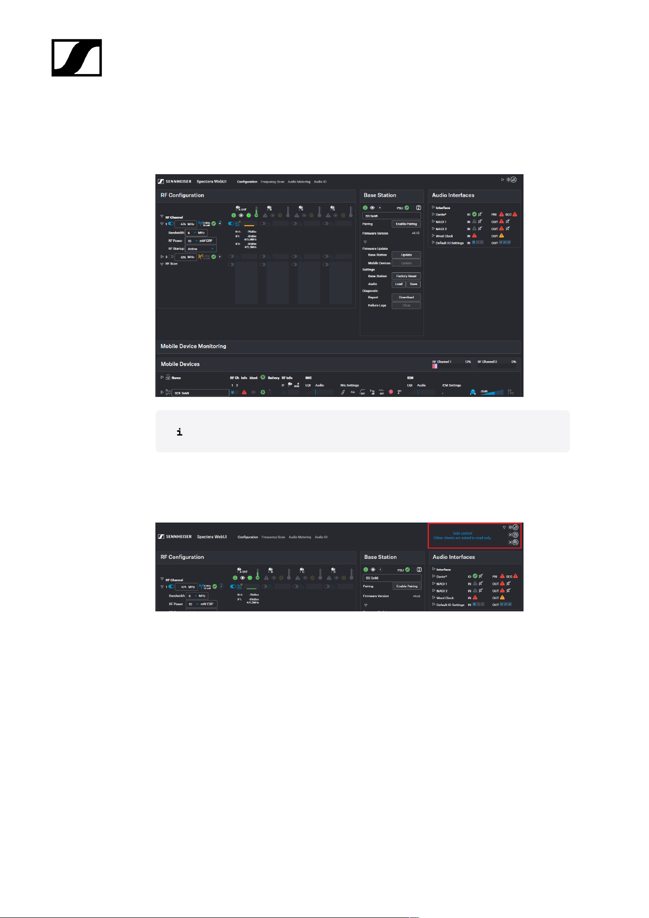
Configuration
Under Configuration, you can set the essential settings for the RF channel, antenna, Base
Station and mobile devices.
Please navigate to the desired chapters by clicking on the related information.
General settings
Overview of the general settings and messages.
You can find the following settings in the top right corner:
• Dark / light mode (see Enabling dark theme)
• Solo control (see Enabling solo control)
• Data collection (see Enabling/disabling data collection)
Messages can be found here as well (see General messages).
Enabling dark theme
You can enable a dark theme for the WebUI surface.
94
| 4 - Instruction manual
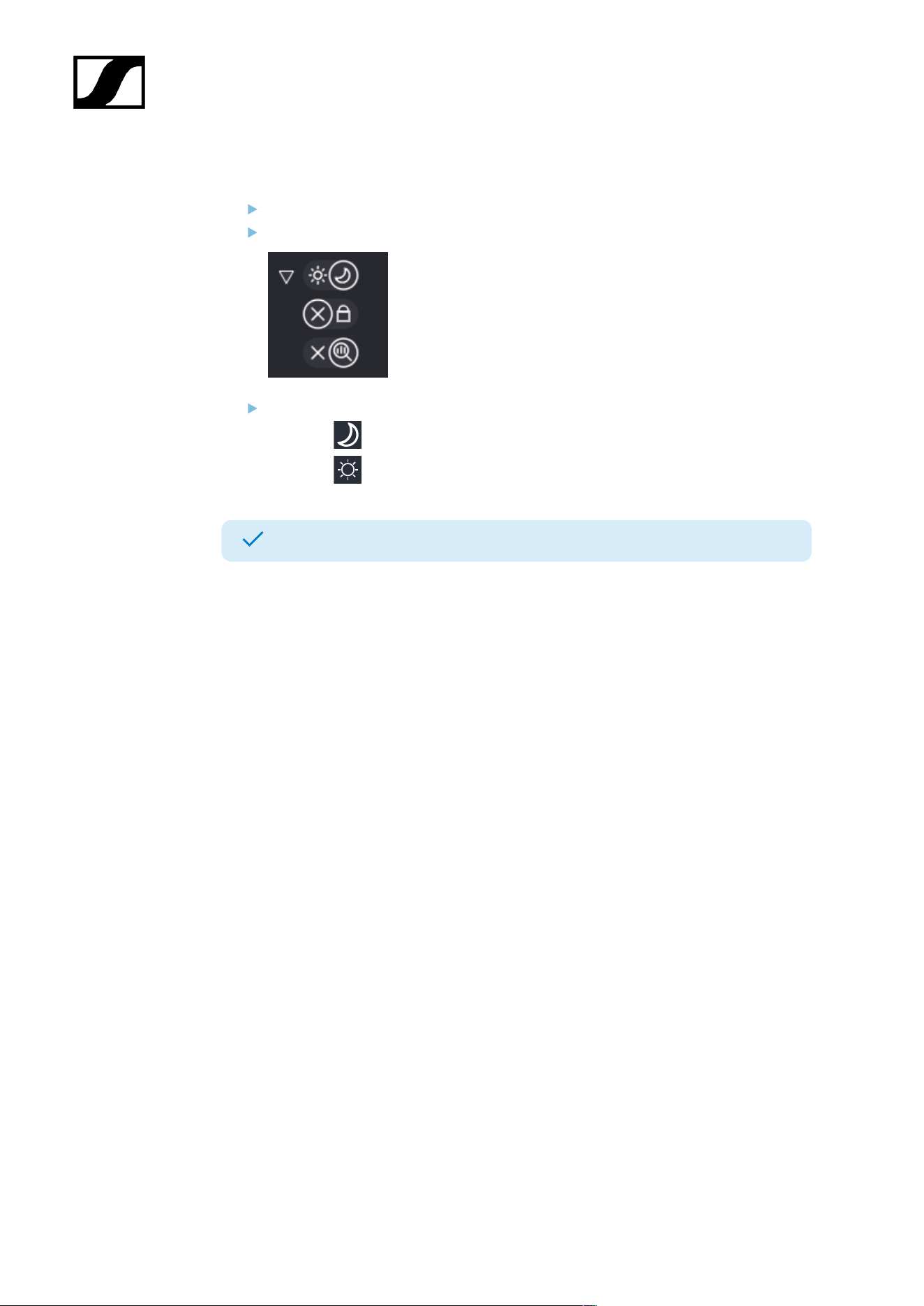
To enable the dark theme:
On the start page, navigate to the top navigation bar at the top right.
Click the triangle to expand the settings.
Click:
• the to enable the dark theme.
• the to enable the light theme.
The dark theme has been enabled.
95
| 4 - Instruction manual
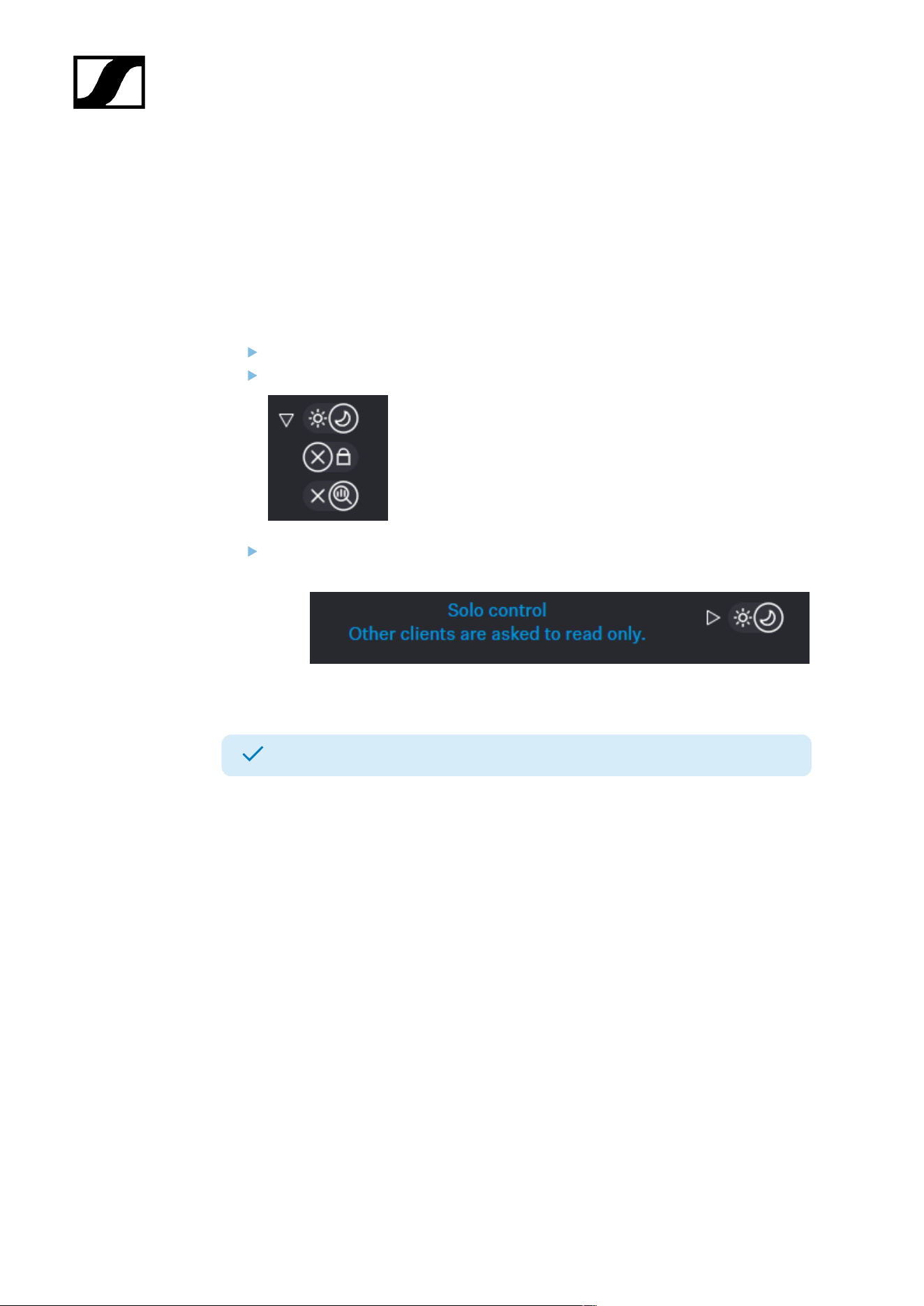
Enabling solo control
You can enable solo control to restrict configuration changes to a single user.
If solo control is enabled, other users cannot change the settings and have read-only access.
To enable or disable solo control:
On the start page, navigate to the top navigation bar at the top right.
Click the triangle to expand the settings.
Click:
• the lock to enable solo control
• the X to disable solo control.
Solo control has been enabled or disabled.
96
| 4 - Instruction manual
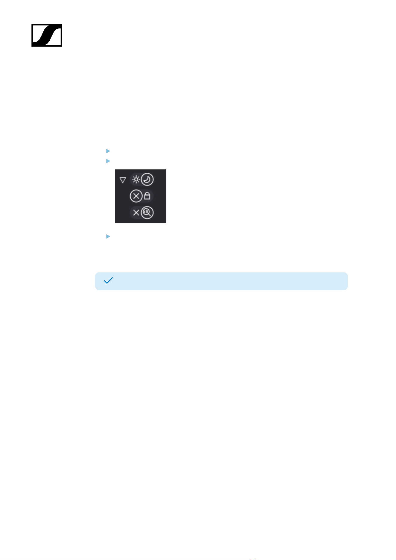
Enabling/disabling data collection
Spectera collects operational data to enhance stability and functionality.
The data is pseudonymized to ensure there is no direct personal reference.
To enable/disable data collection:
On the start page, navigate to the top navigation at the top right.
Click on the triangle to expand the settings.
Click on:
• the X to stop data collection
• the magnifying glass to enable data collection.
Data collection has been enabled/disabled.
97
| 4 - Instruction manual
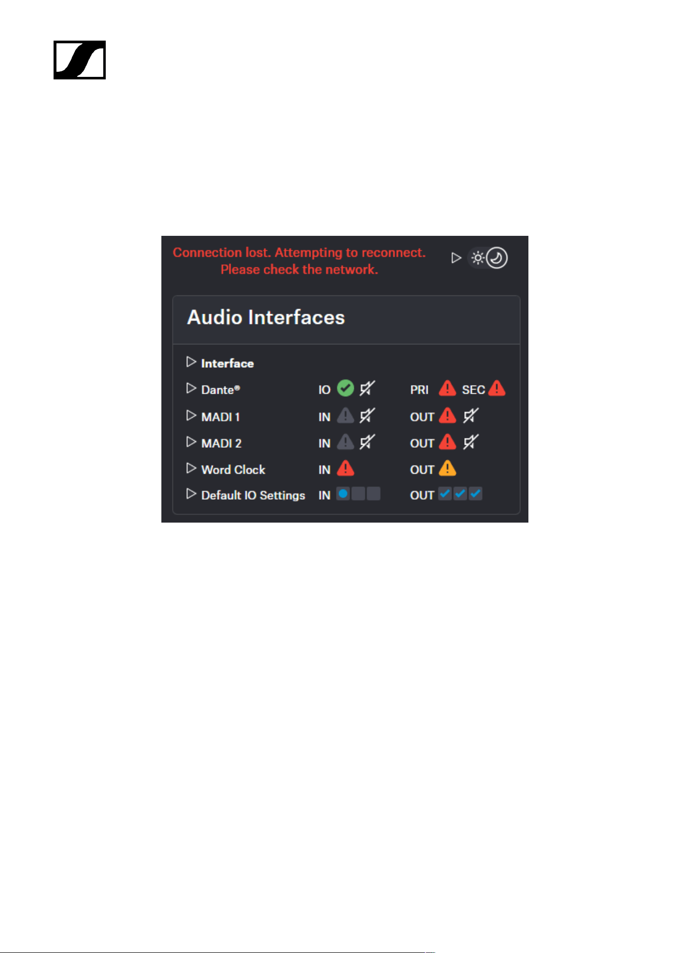
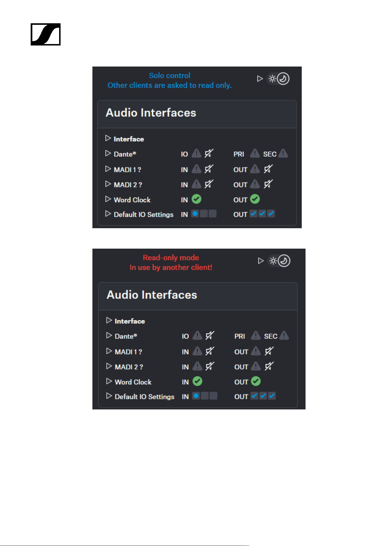
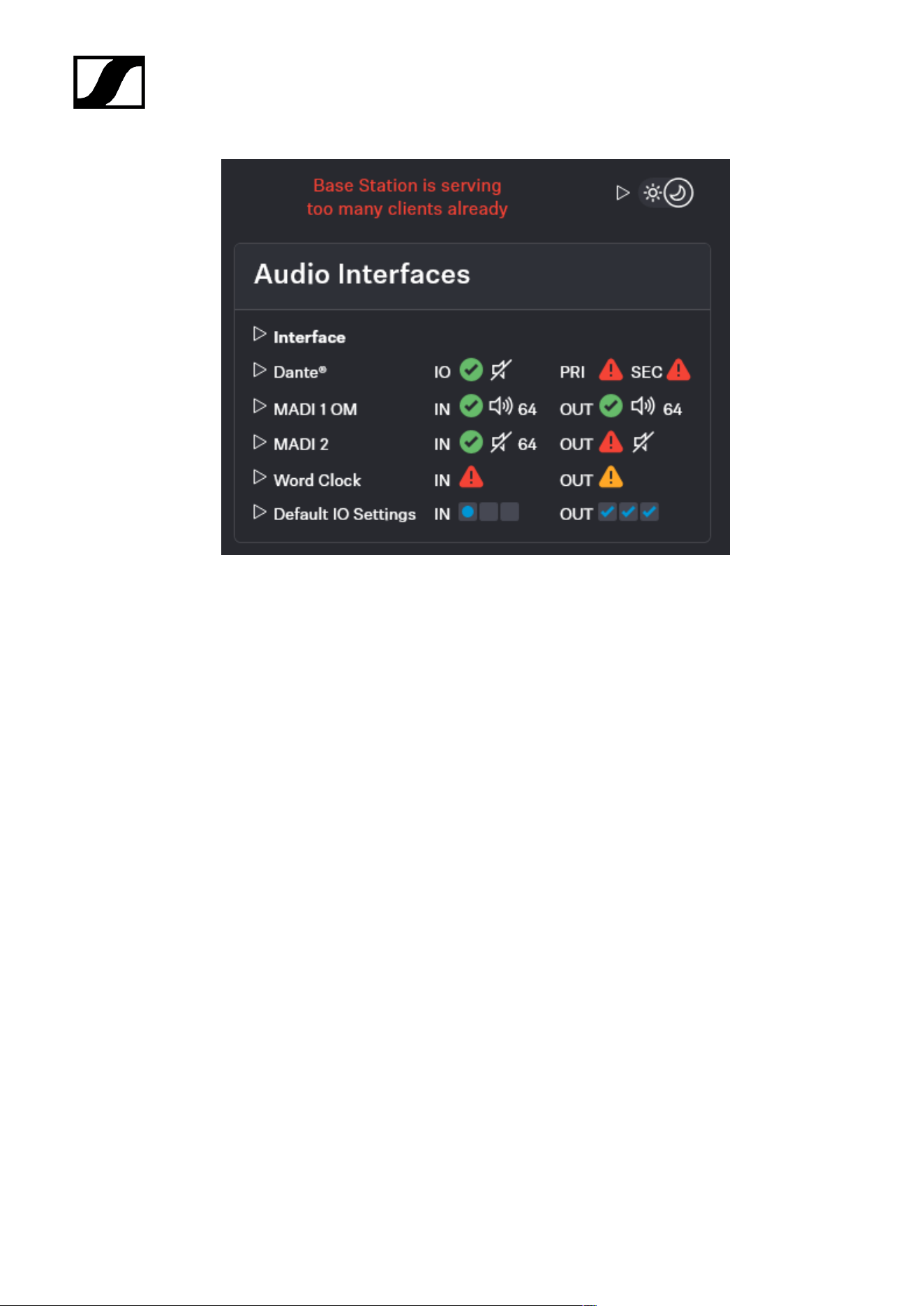
General messages
Overview of the general messages.
The messages can appear on the top right corner.
Connection is lost
Solo control and read-only mode
If you enabled solo control:
98
| 4 - Instruction manual
If you have read-only mode:
If to many clients accessing the WebUI:
99
| 4 - Instruction manual
100
| 4 - Instruction manual
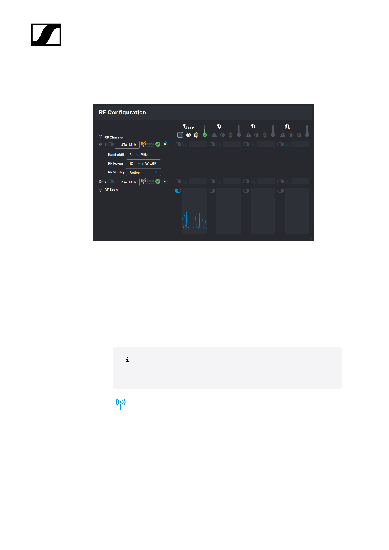
RF configuration
Here you can set up your RF channel and check the status of local permissions, your
connected antenna, and any potential frequency interference in the surrounding area.
RF Channel
• Display of two possible configurable RF channels RfC 1 and RfC 2
• Display of the antenna (A-D) assigned to the RF channel
Frequency
• Settings for frequency of the RF channel
• The input is accepted via the ENTER key
The input cannot be accepted by switching with
TAB
.
• Status indication of the RF channel with current settings
101
| 4 - Instruction manual
• Permission indication for local country based on RF channel settings
• Valid properties acc. to the license and local regulations
• Invalid properties acc. to the license and local regulations
The frequency and bandwidth must comply with local regulations.
• Capacity utilization of the entire RF bandwidth in %
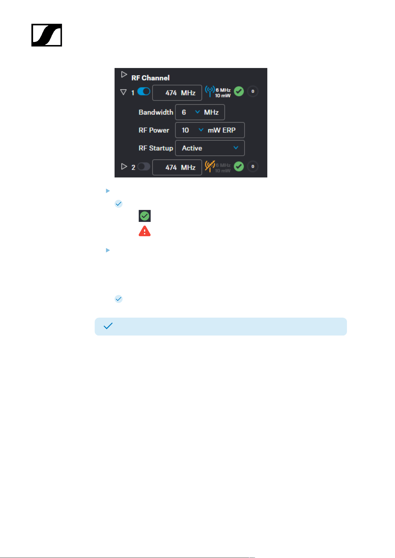
Bandwidth
• Settings for bandwidth of the RF channel
The input cannot be accepted by switching with
TAB
.
The frequency and bandwidth must comply with local regulations.
Permission is displayed via the icons (valid) and (invalid).
RF Power
• Setting for the transition power of the transmitter
The frequency and bandwidth must comply with local regulations.
Permission is displayed via the icons (valid) and (invalid).
RF Startup
• Settings for the first RF start after switching off the device or when waking up the
device after it has been in standby mode.
102
| 4 - Instruction manual
Antenna
• Display of available antennas (A-D)
• Readiness status of the RF channel
• green (successfully paired and ready)
• gray (assigned RF channel not on air)
• yellow (high temperature or packet jitter)
• red (error, for example: PoE malfunction, critical temperature)
• red flashing (unconnected: antenna is configured but not connected)
• Identification button for configured antenna (flashes white 3x)
• LED color of the antenna LED (color can be changed for the states connected or
muted individually)
• Current antenna temperature (switch between Celsius and Fahrenheit)
• Indication for active RF
• Frequency indication without any interference
• Frequency indication with interference in the surrounding area
Configuring RF channels
Here you can find out how to configure the RF channel correctly from the outset.
The current local permissions are displayed when the frequency is selected.
To configure an RF channel:
In the top bar, navigate to Configuration > RF Configuration.
For channel RF1, enter the frequency under 1 and confirm with ENTER.
103
| 4 - Instruction manual
Next, select the Bandwidth and the RF Power for your location.
The applicability of your settings is indicated by an icon:
• green: applicable
• red: not applicable
Under RF Startup, select the mute option for the configured RF channel:
• Active
• Muted
• Last state = When switching on or leaving standby mode, the last used RF
state is restored
The RF Channel has been assigned to the operating antenna.
The RF Channel has been configured.
104
| 4 - Instruction manual
Assigning an antenna to an RF channel
You can choose between up to four connected antennas to assign them to your two
possible RF channels.
For additional reliability in terms of redundancy or to extend your range, you can
assign up to four antennas per channel and use them simultaneously.
The antennas can be assigned and unassigned, e.g. to perform an RF scan or to switch
between the configured RF channels.
To assign an antenna for an RF channel:
In the top bar, navigate to Configuration > RF Configuration.
In your RF channel row, click on the toggle switch next to the utilization and
interference icon .
The toggle switch turns blue . The antenna has been assigned to the RF
channel and any potential interference is indicated by the icon.
The antenna has been assigned to a specific RF channel.
105
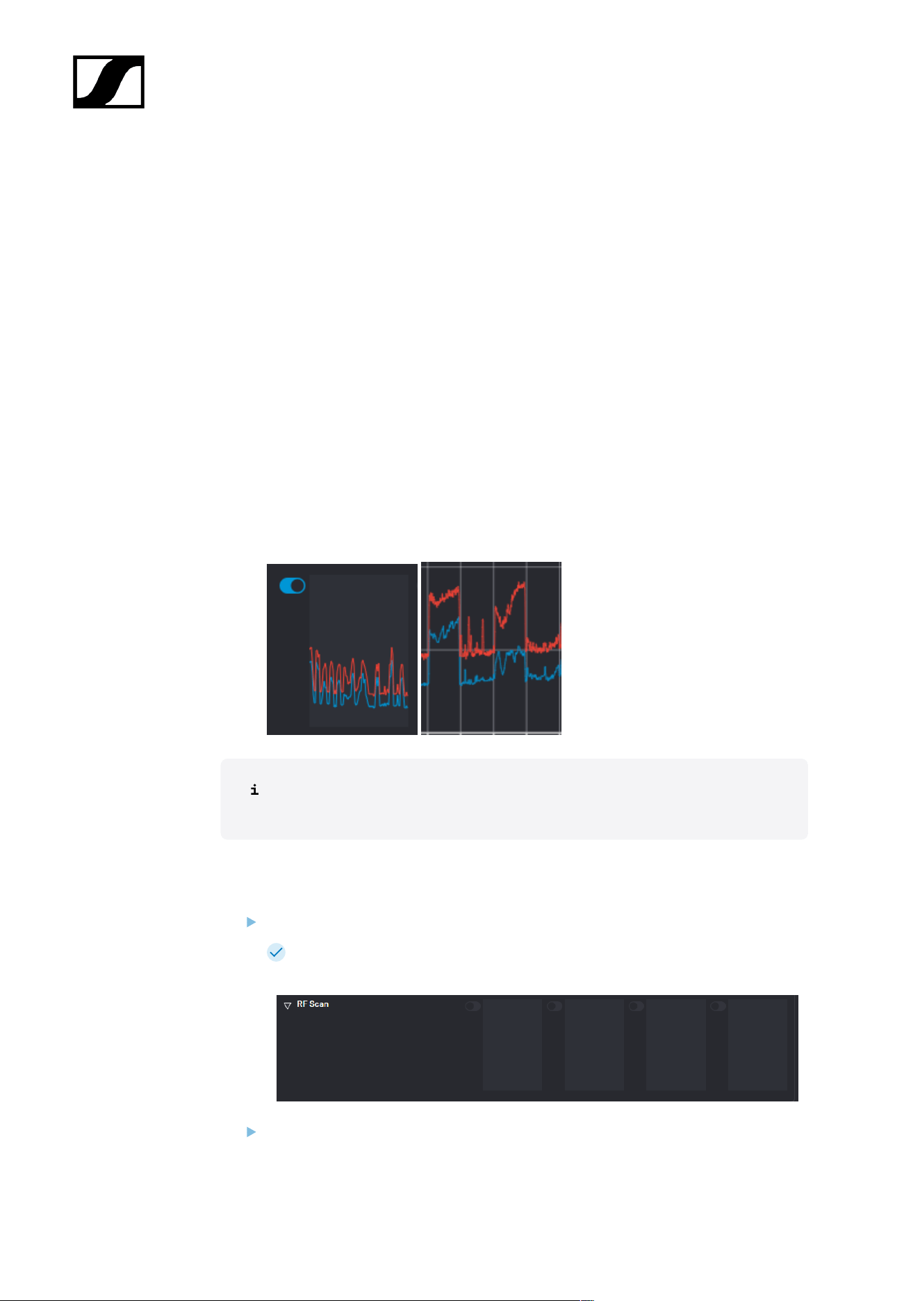
| 4 - Instruction manual
Scanning the RF frequency
You can run a frequency scan to check the current frequency situation in your surrounding
area.
The frequency scan provides an overview of the frequency situation in your location. You can
save the antenna configuration as a .csv info file. This file can be used as a backup file to
recapitulate your settings or as local frequency information for your specific environment.
You can scan the frequencies of all antennas connected to the Base Station.
The scan can be initiated:
• via the RF configuration tab to see a small extract without any details or
• via the Frequency Scan tab for a detailed overview of the frequency situation.
The scan results will be displayed in two different curves:
• Peak (red) = Maximum value
• RMS (blue) = Average power or strength
Please note that the antenna must not be assigned to an RF channel before
scanning (see Assigning an antenna to an RF channel).
To scan the RF frequency via the RF configuration tab:
In the top bar, navigate to Configuration > RF Configuration.
Under the RF Scan drop-down menu, there are four toggle switches that enable
and disable the scan function for each connected antenna.
Click on the toggle switch of the antenna to be scanned in order to start an immediate
scan.
106
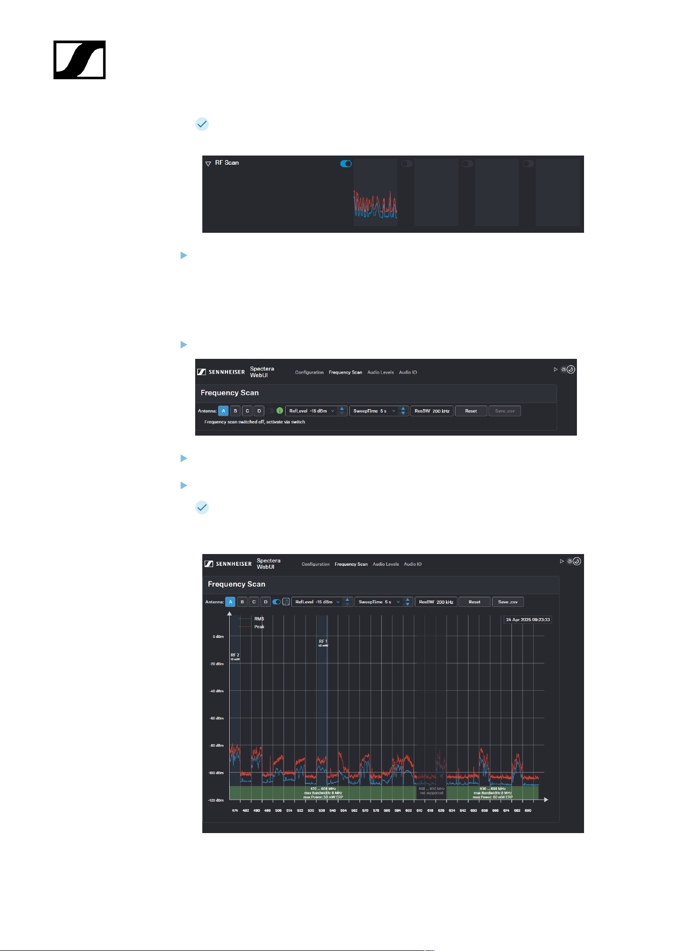
| 4 - Instruction manual
The square is highlighted with a blue dot and the scan result is displayed in a
small frequency curve after approx. 5 seconds.
In order to view the results,
• click on the small frequency icon or
• navigate to Frequency Scan in the top bar.
To scan the RF frequency via the Frequency Scan tab:
In the top bar, navigate to the tab Frequency Scan.
Select your antenna to be scanned and adjust your desired settings.
Switch on the toggle to start the scan.
The frequency scan is started and the result is displayed in a detailed frequency
diagram. Supported frequency ranges are shown in green and unsupported
ranges in gray.
107
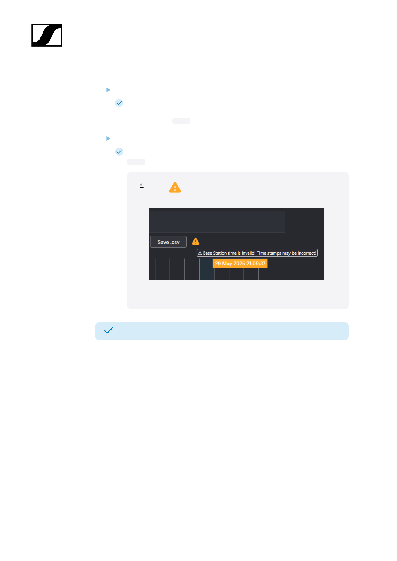
| 4 - Instruction manual
To reset a scan:
Click on Reset.
The current scan will be reset.
To save the scan results as .csv :
Click on Save.csv.
The antenna configuration has been downloaded locally to your computer as a
.csv file.
If a appears after Save.csv, the time on the Base Station is
invalid.
Connect the Base Station to the Internet to get the correct time.
The frequency of your connected antenna has been scanned.
108
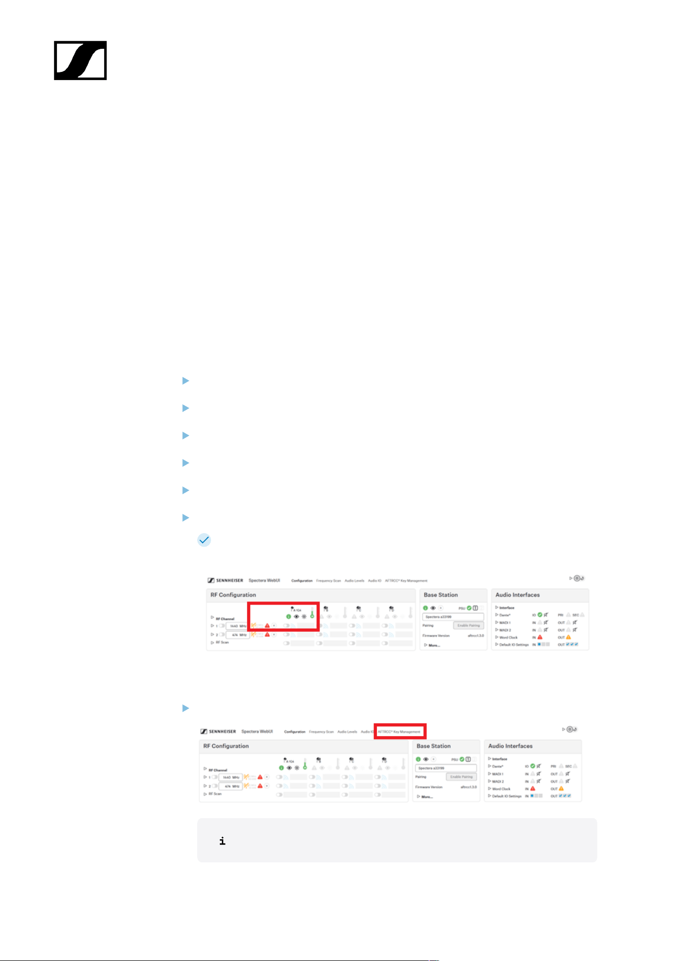
| 4 - Instruction manual
Managing the AFTRCC e-key for 1G4 in the US only
Configure your Spectera system to use an e-key for compliant operation.
Prerequisites
• Spectera Base Station
• DAD 1G4
• SEK 1G4
• Laptop
• Internet connection
• Bootstrapped and activated Spectera system
• Spectera US license (Zone 02)
To set up the basics:
Switch the Base Station on.
Connect your laptop via network to the control port of the Base Station.
Connect the DAD 1G4 to the Base Station.
Get the IP adress from the display.
Start the WebUI in your browser by entering https://deviceIP.
Log in to the WebUI.
You can see one 1G4 antenna connected, but it cannot be enabled (indicated by a
red triangle).
To open the AFTRCC key management:
Open the AFTRCC Key Management tab at the top.
This tab is only availabe with a licence zone 02 in the USA.
109
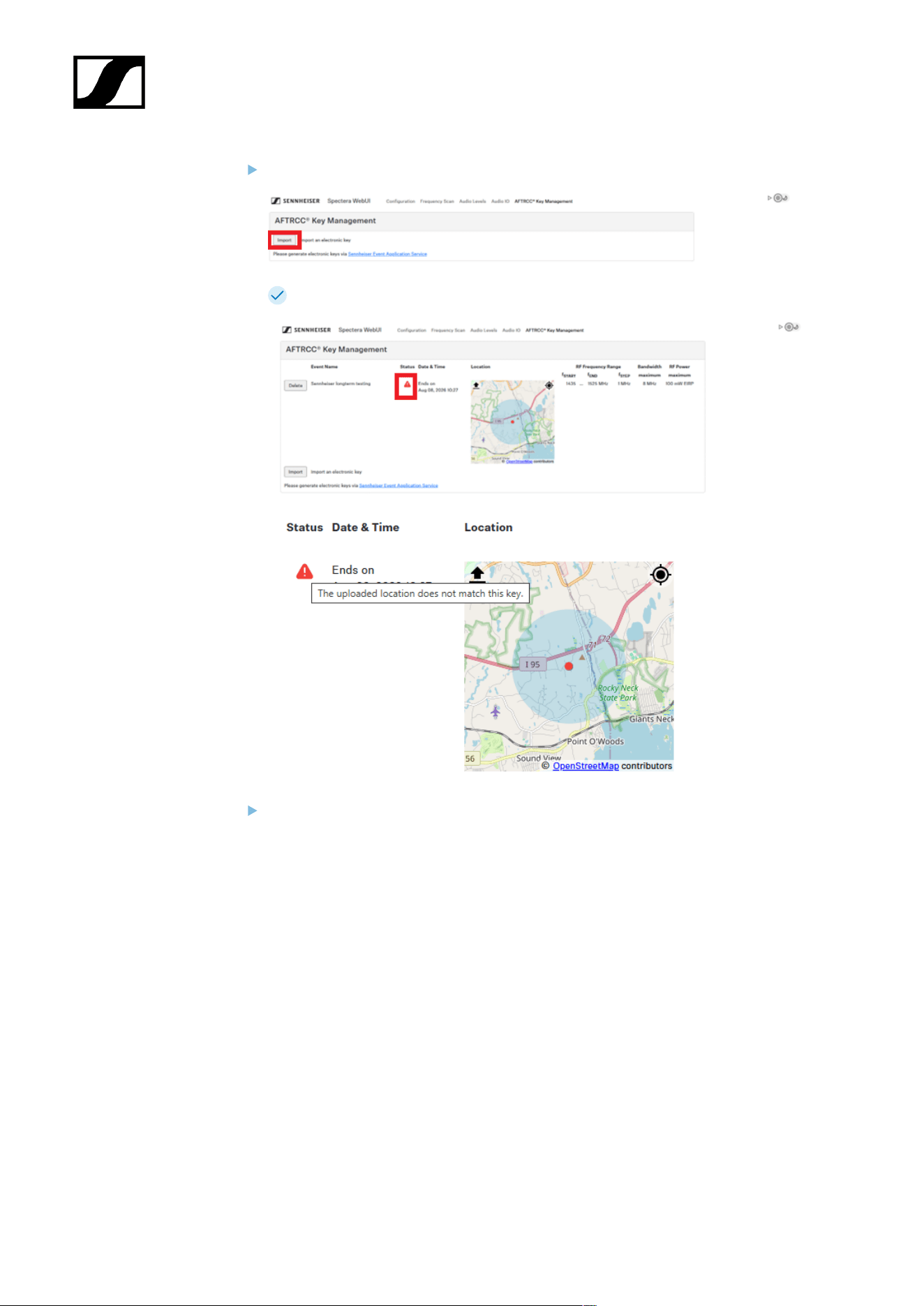
| 4 - Instruction manual
Click on Import and select the e-key from your file system.
A red triangle shows information about why it is not working.
Make sure that your Spectera system is connected to the Internet and can get the
current valid time and date.
The Base Station can maintain valid time and date for up to two weeks, when neither
internet connection nor mains power is available.
110
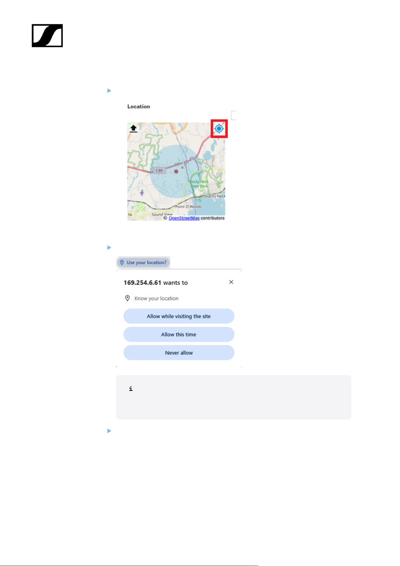
| 4 - Instruction manual
To update and upload the location:
Press the localization icon in the map.
If the system asks for access to the location service, grant it.
Sometimes the browser localization needs some time after granting
access to location service. You can press the localization icon again to
improve accuracy.
Upload your location by pressing the upload button in the map.
111
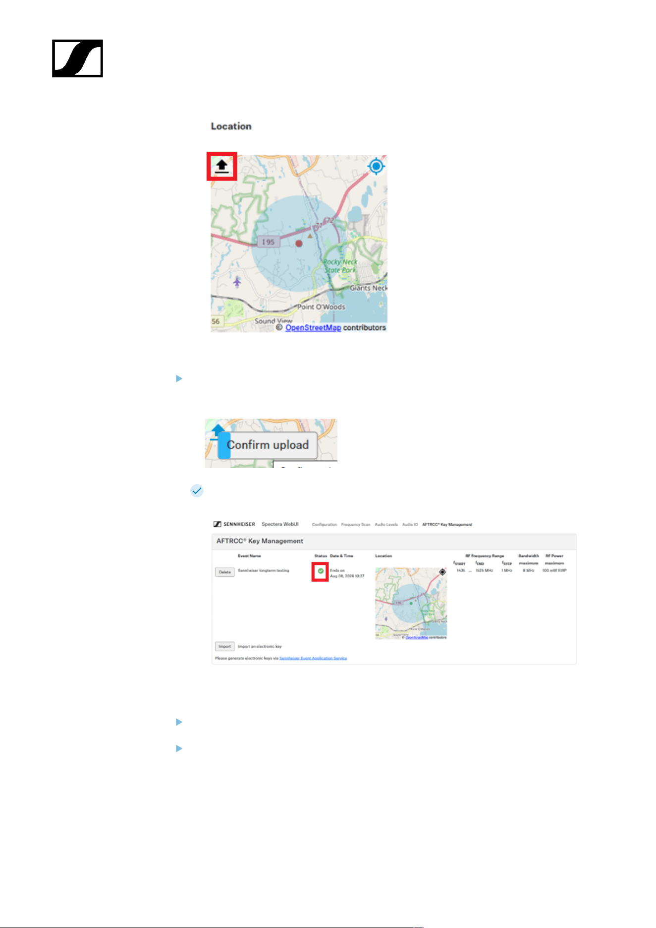
| 4 - Instruction manual
Click the confirmation button. You hereby confirm, that the current shown location is
correct.
The status changes to green, if all the necessary
prerequisites are met (time, date and location).
To configure and enable the RF channel:
Open the Configuration tab at the top.
Configure the frequency of the RF channel to one valid frequency as defined in the e-
key.
112
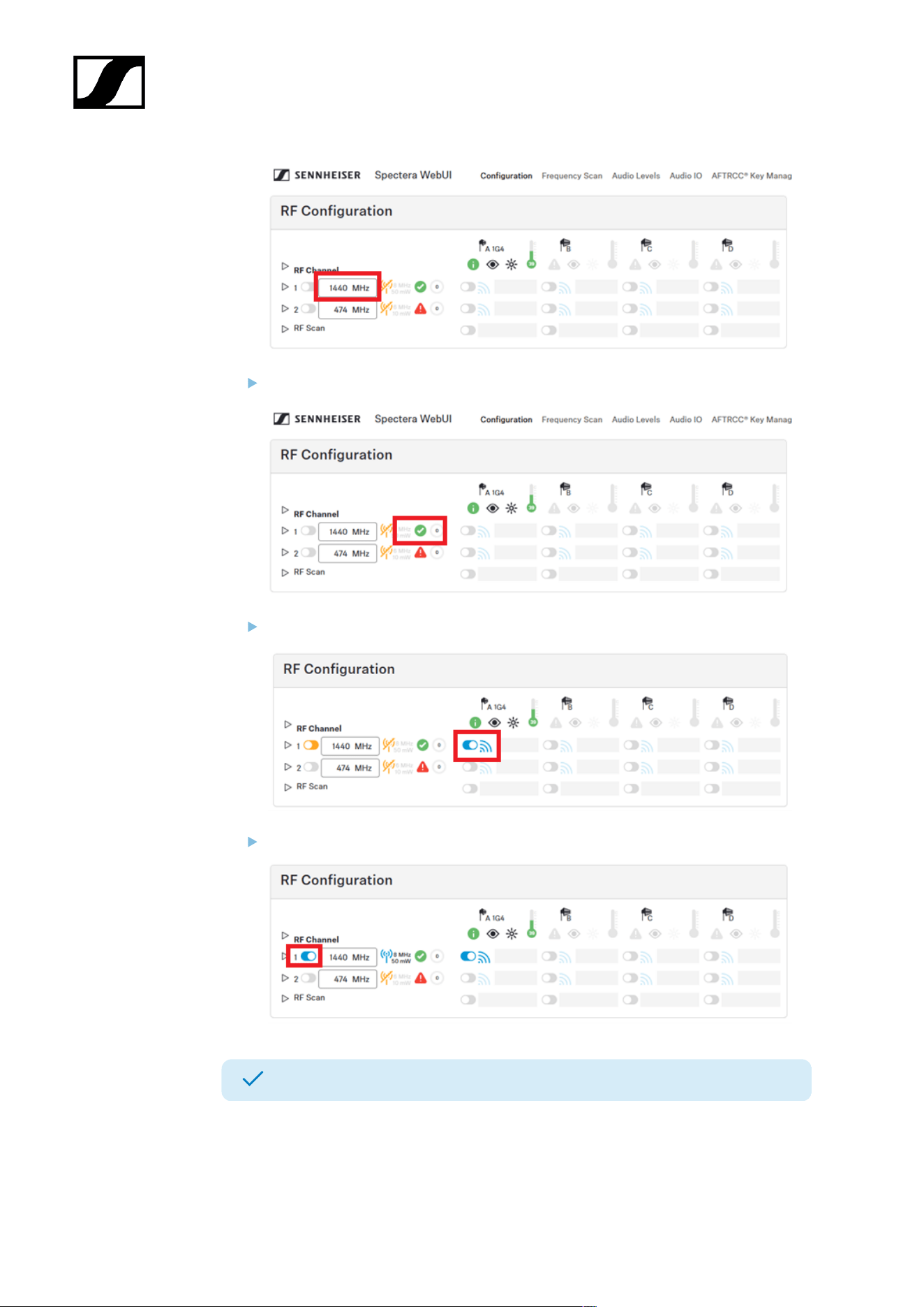
| 4 - Instruction manual
Check if the RF channel can be used as configured.
Enable the antenna.
Enable the RF channel.
The system is now working within the parameters of the e-key.
113
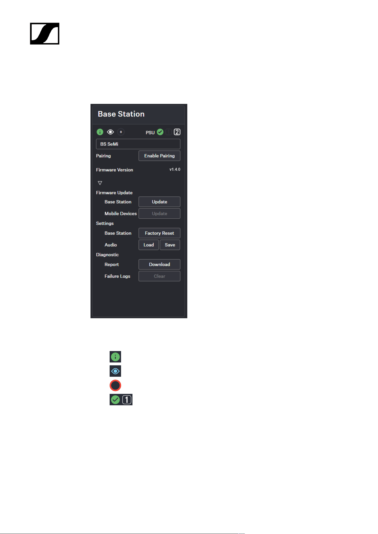
| 4 - Instruction manual
Base Station
Here, you can check the basic settings of the Base Station and easily perform tasks such as
firmware updates, walk tests, or restoring it to factory settings.
General
• Device state color
• Identify button (see Identifying the Base Station)
•
0
Indication for pending actions
• Connection status and number of connected power supply units
• Name of your Base Station (see Changing the device name)
Enable Pairing
• Triggers the Pairing function of the Base Station for 300 sec. (see Pairing/unpairing
mobile devices)
114
| 4 - Instruction manual
Firmware Update
• Base Station
• Update service for the Base Station (see Updating the firmware (Base
Station))
• Mobile Devices
• Update service for mobile devices (see Updating the firmware (mobile
devices))
Settings
• Base Station
• Factory Reset - resets the Base Station to the factory defaults (see Resetting
the Base Station)
• Audio
• Saving/loading audio settings as .json file (Saving/loading audio settings)
Diagnostic
• Report: Provides archived support information of the product as a download.
The automatically generated file contains basic information about the
product and the last saved product configuration before a potential
failure. In case of support, this file should be saved and sent to the support
team.
• Failure Logs: Deletes all error messages saved under "Report" that occurred during
runtime.
Changing the device name
You can change the device name for your Base Station.
For security reasons, please do not enter any sensitive personal data as the
device name.
To change the device name:
In the top bar, navigate to Configuration > Base Station.
Edit the name under Name and confirm with ENTER.
The name is immediately transmitted to the Base Station and saved.
115

| 4 - Instruction manual
The device name has been changed.
116
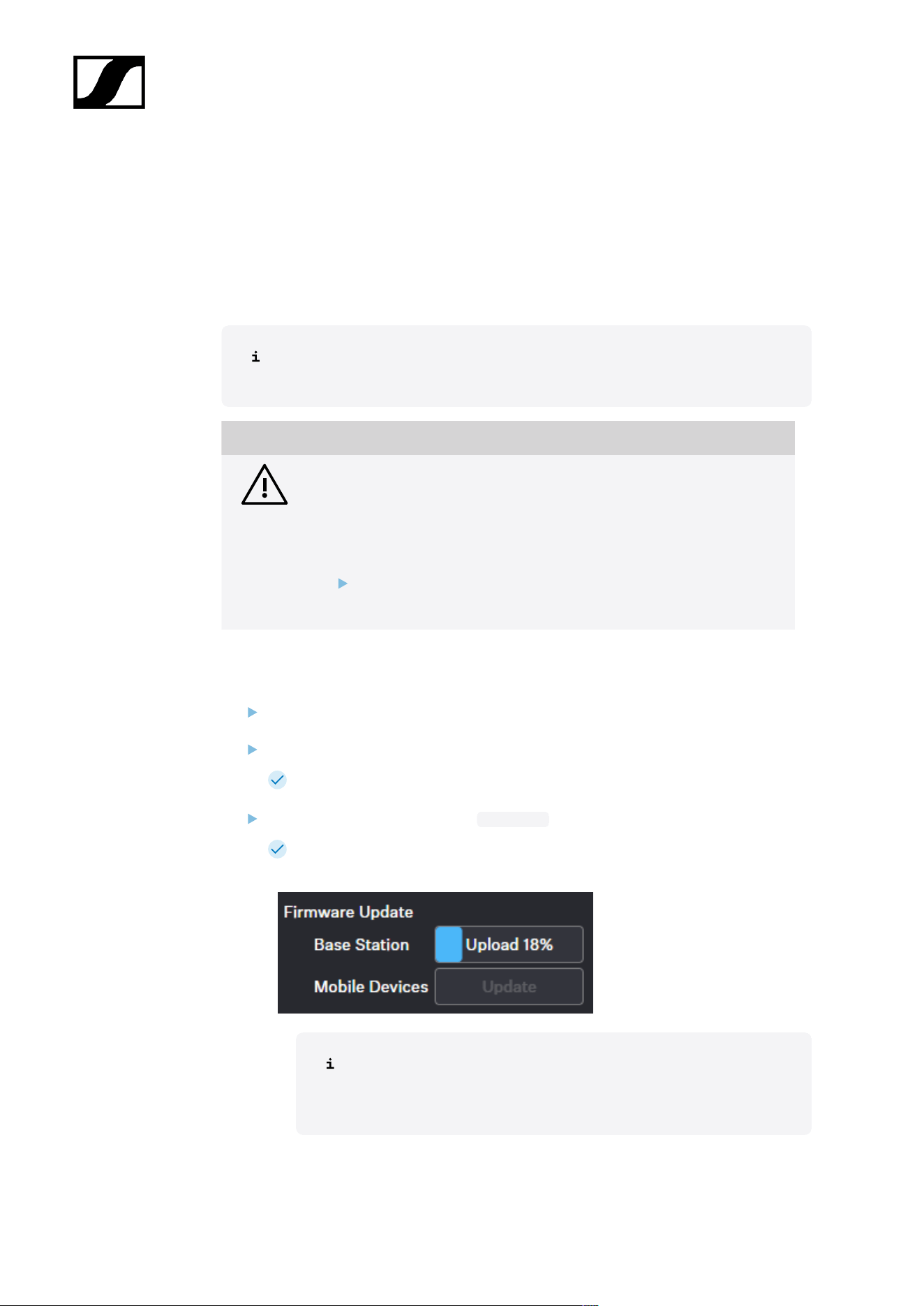
| 4 - Instruction manual
Updating the firmware (Base Station)
The firmware version of the Base Station can be downloaded and updated manually.
The firmware version for the Base Station also includes the latest versions for the antennas
and the mobile devices. While the antennas are updated automatically, the updates for the
mobile devices must be started explicitly.
Please download the latest firmware version for your Base Station under:
sennheiser.com/spectera-base-station.
NOTICE
Data loss during firmware update
The audio transmission is interrupted during the firmware update of the
Base Station, the antenna or the mobile device.
After the firmware update, the device is restarted automatically.
Do not update the firmware during an active live audio
transmission.
To update your Base Station firmware:
In the top bar, navigate to Configuration > Base Station.
Under Firmware Update > Base Station click on Update.
A new upload window opens.
Select the manually downloaded .sennpkg file.
The firmware file has been selected. The firmware starts the update
automatically. The update process is indicated by the current percentage value.
After the successful update, the Base Station restarts and
automatically begins the update on the connected antennas. Please
refresh your browser after the entire update process.
117

| 4 - Instruction manual
The firmware has been updated once the update is installed.
118
| 4 - Instruction manual
Updating the firmware (mobile devices)
The update of the firmware version of mobile devices can be initiated using the Update
button.
The latest firmware version for the mobile devices will be delivered with the latest firmware
version of the Base Station. To update to a new version, the update process must be
initialized individually.
Please note that firmware versions are not backward compatible. The latest
compatible version is included in the firmware update package for the Base
Station.
NOTICE
Data loss during firmware update
The audio transmission is interrupted during the firmware update of the
Base Station, the antenna or the mobile device.
After the firmware update, the device is restarted automatically.
Do not update the firmware during an active live audio
transmission.
To update your mobile device firmware:
In the top bar, navigate to Configuration > Base Station.
Under Firmware Update > Mobile Devices click on Update.
The update process will start automatically and show the progress as a
percentage . After a successful update, the mobile device is restarted and
paired automatically.
The firmware update is a disruptive process. The mobile devices will
update and reboot in sequence. This process will take roughly 20
seconds: during this time audio will be lost. Please stay in reach of
the Base Station, do not remove the battery from the mobile devices
during the process and do not close the application.
The firmware has been updated.
119
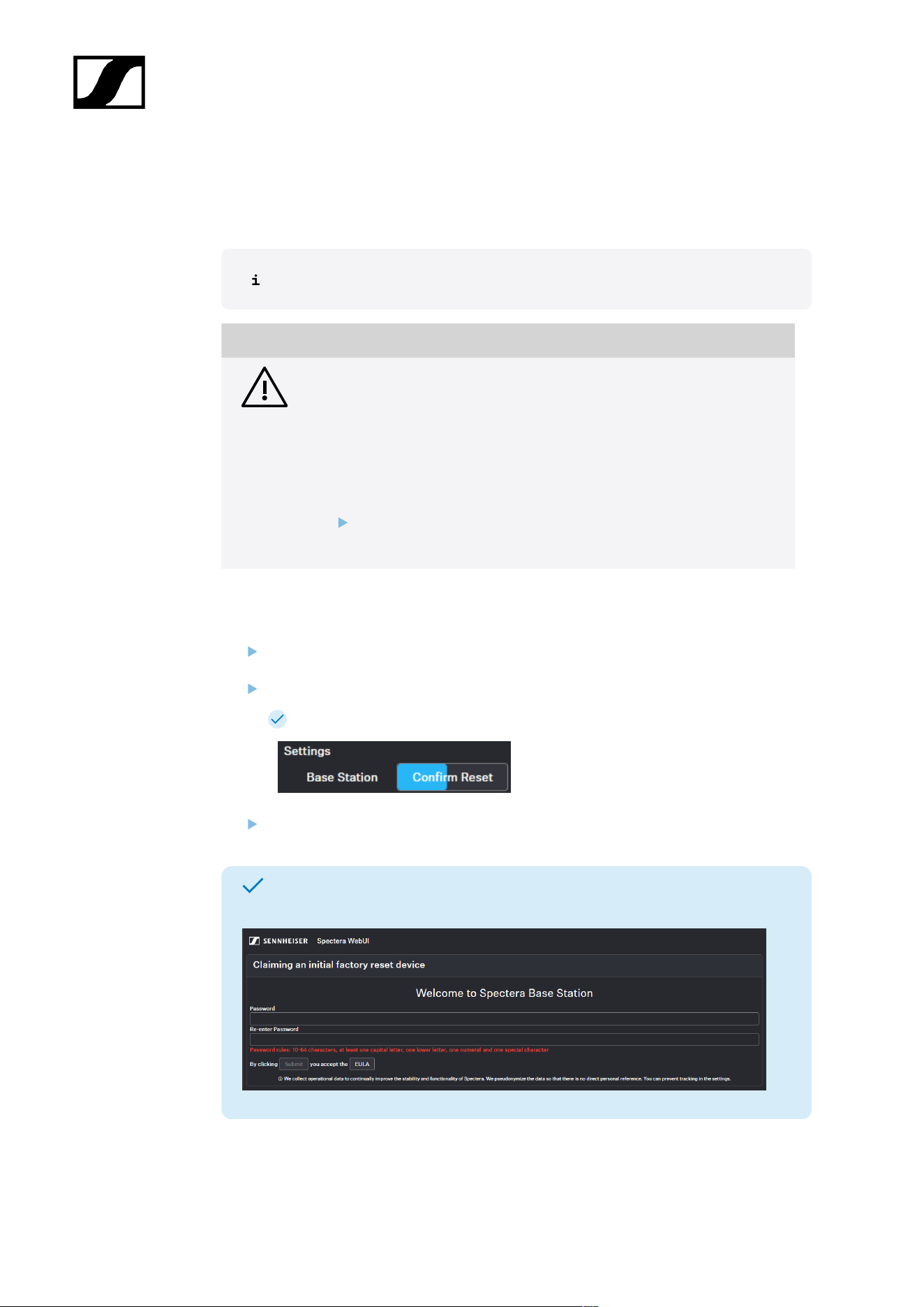
| 4 - Instruction manual
Resetting the Base Station
You can reset the Base Station to the factory settings remotely.
You can also reset the Base Station to the factory settings directly via the device.
NOTICE
Loss of data after resetting to factory settings
All settings are reset to the factory settings!
All devices will be unpaired and all audio routes will be deleted!
The user password will be reset!
The entitlement will remain.
Make sure that no connections are being actively used at the time
of the reset.
To reset the Base Station remotely:
In the top bar, navigate to Configuration > Base Station.
Click on Settings and then on Factory Reset.
A countdown timer will be displayed (highlighted in blue).
Press Confirm Reset to confirm the factory reset.
The Base Station has been reset. Upon re-login, you will be prompted to set a new
password for the device.
120
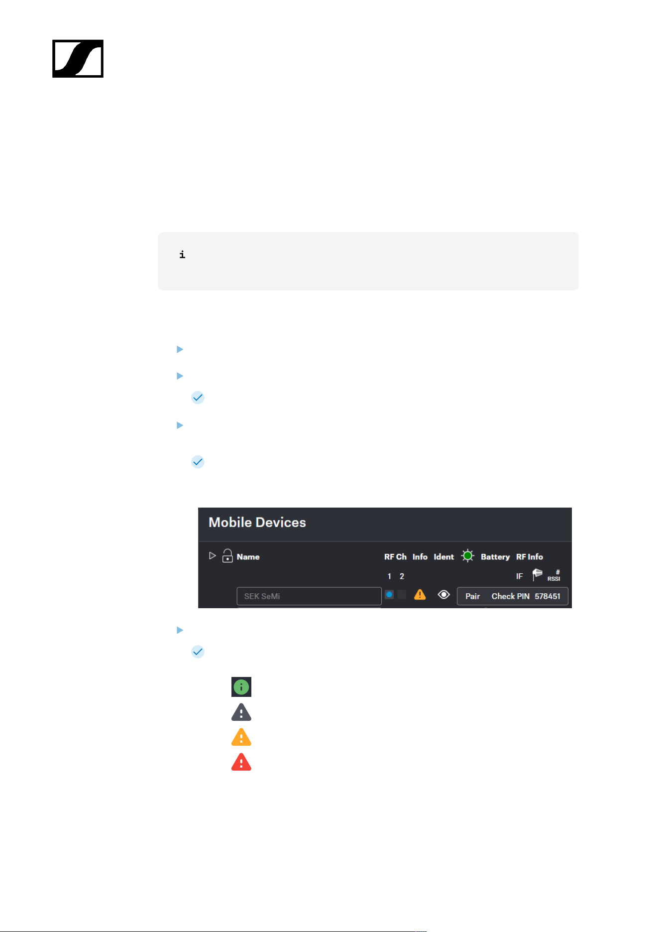
| 4 - Instruction manual
Pairing/unpairing mobile devices
In the WebUI, you can pair up to 128 mobile devices to a Base Station within one RF
channel.
Mobile devices can only be paired and operated with one Base Station at a time. If a mobile
device is to be used with another Base Station, it must first be paired again.
Please unmute at least one RF channel before pairing if this was not done
automatically.
To pair a mobile device:
In the top bar, navigate to Configuration > Base Station.
Click on Enable Pairing.
The Base Station starts the pairing process for 300 seconds.
Switch on your mobile device and activate Pairing Mode if it has not been activated
automatically (Switching the SEK on and off/Switching the SKM on and off).
After a few seconds, the available mobile devices are displayed in the list below
under Mobile Devices. A verification PIN is displayed on the mobile device and in
the WebUI.
Verify the PIN on the mobile device and click on Pair.
The mobile device has been paired successfully. The device state color changes
to:
• green (successfully paired)
• gray (assigned RF channel not on air)
• yellow (firmware mismatch) or
• red (unconnected, no RF channel selected, not available)
121

| 4 - Instruction manual
To unpair a mobile device:
To unpair a paired device, the audio links must first be deactivated.
In the top bar, navigate to Configuration > Mobile Devices.
Click on the button Unpair > Confirm in the line of the mobile device to be unpaired.
The mobile device has been successfully unpaired.
The mobile devices have been successfully paired/unpaired.
122

| 4 - Instruction manual
Identifying the Base Station
You can remotely identify your Base Station.
To identify the Base Station:
In the top bar, navigate to Configuration > Base Station.
Click on the Identify icon.
The icon on the Base Station card flashes. The Base Station display shows
"Identify".
The Base Station has been identified.
123

| 4 - Instruction manual
Saving/loading audio settings
You can save your audio settings and load them at a later time.
In order to apply the audio settings, a familiar ID of the previously assigned
mobile device is expected in connection with the hardware configuration of the
Base Station described in this document. Unknown IDs of the mobile device or
unknown hardware configurations will result in the settings not being accepted
successfully.
The audio settings can be exported in a .json file.
To save your audio settings:
In the top bar, navigate to Configuration > Base Station.
Under Settings click on Save.
Your audio settings have been exported as a .json file.
To load your saved audio settings:
In the top bar, navigate to Configuration > Base Station.
Under Settings click on Load.
A new upload window opens.
Select your saved file and click on Open.
Your audio settings file has been successfully loaded.
The audio settings have been successfully saved/loaded.
124
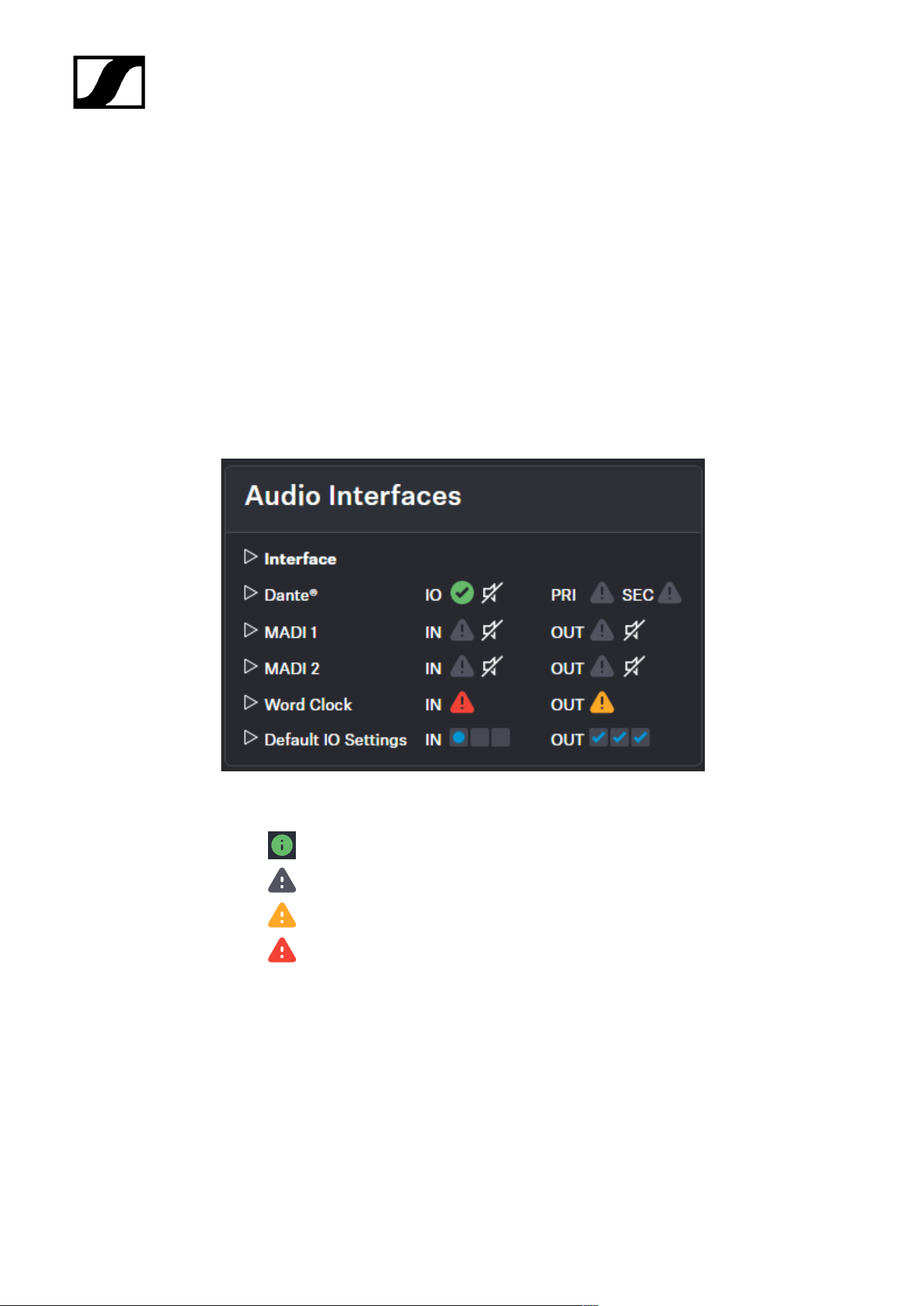
| 4 - Instruction manual
Audio interfaces
Here you can monitor all available interfaces and manage the outputs.
A built-in sample rate converter can be used to convert the outputs to predetermined
frequencies and generate a custom sample rate for any audio channel. The following settings
are available for MADI 1, MADI 2 and Word Clock interfaces:
• Leader 48 kHz
• Leader 96 kHz
• Follow MADI 1 Input
• Follow MADI 2 Input
• Follow World Clock Input
• Follow Audio Network
The interface status is indicated by the following colors:
• OK
• Not used
• Attention, e.g.: "fallback active"
• Warning, e.g.: "input not toggling"
Audio Network
• Dante®
• Dante® Primary
• Dante® Secondary
125
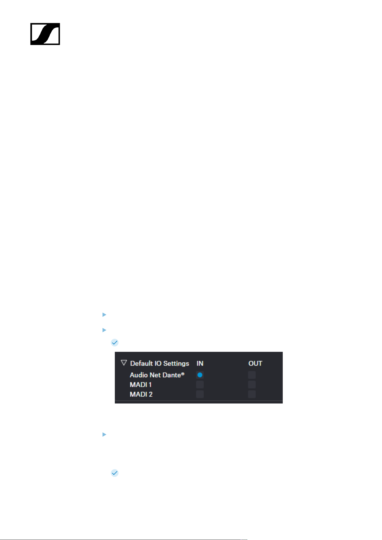
| 4 - Instruction manual
MADI 1
• Input
• Output
MADI 2
• Input
• Output
Word Clock BNC
• Input
• Output
Default Input Interface
• Dante®
• MADI 1
• MADI 2
Selecting the default audio input/output source
You can select the default source for the audio input and output of your audio interface.
To select the default input interface:
In the top bar, navigate to Configuration RF > Audio Interfaces.
Select the input interface under Default IO Settings.
The default input interface has been selected.
To select the clock source output:
Select the desired setting for the clock source under:
• MADI 1
• MADI 2
• Word Clock BNC
The clock source output has been selected.
126

| 4 - Instruction manual
The audio interfaces have been selected.
127
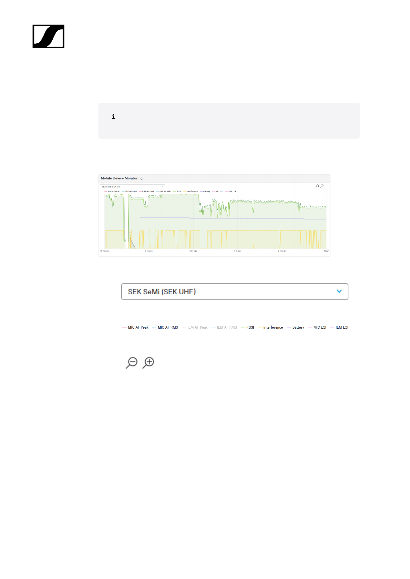
| 4 - Instruction manual
Mobile Device Monitoring
Here you can monitor the live data of the mobile devices as graphs.
The data is live only, can't be zoomed in to a certain point in time and can't be
recorded.
To show the data, click on the grey menu bar Mobile Device Monitoring.
The data is the same as you can see in the mobile device section below.
• Switch between the mobile devices.
• Select the prefered data by clicking on the values or double-click to isolate/show all.
• Zoom in or out from 10 h ago to now.
128
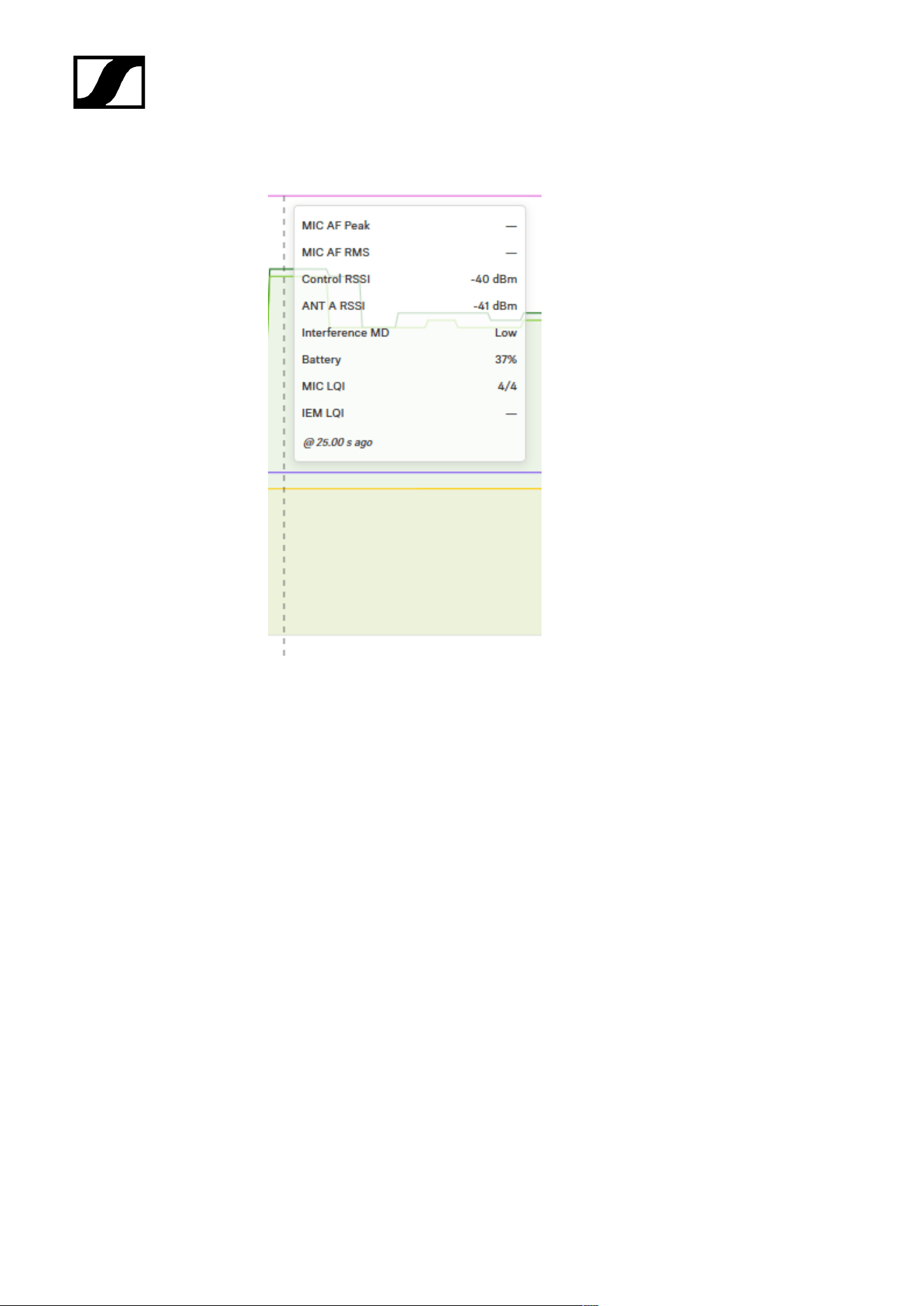
| 4 - Instruction manual
• Hover over the graphs for details.
The RSSI graph shows different parameters
• control channel and
• received signal from up to four antennas.
The Interference will be indicated in four steps.
• None
• Low
• Mid
• High
129
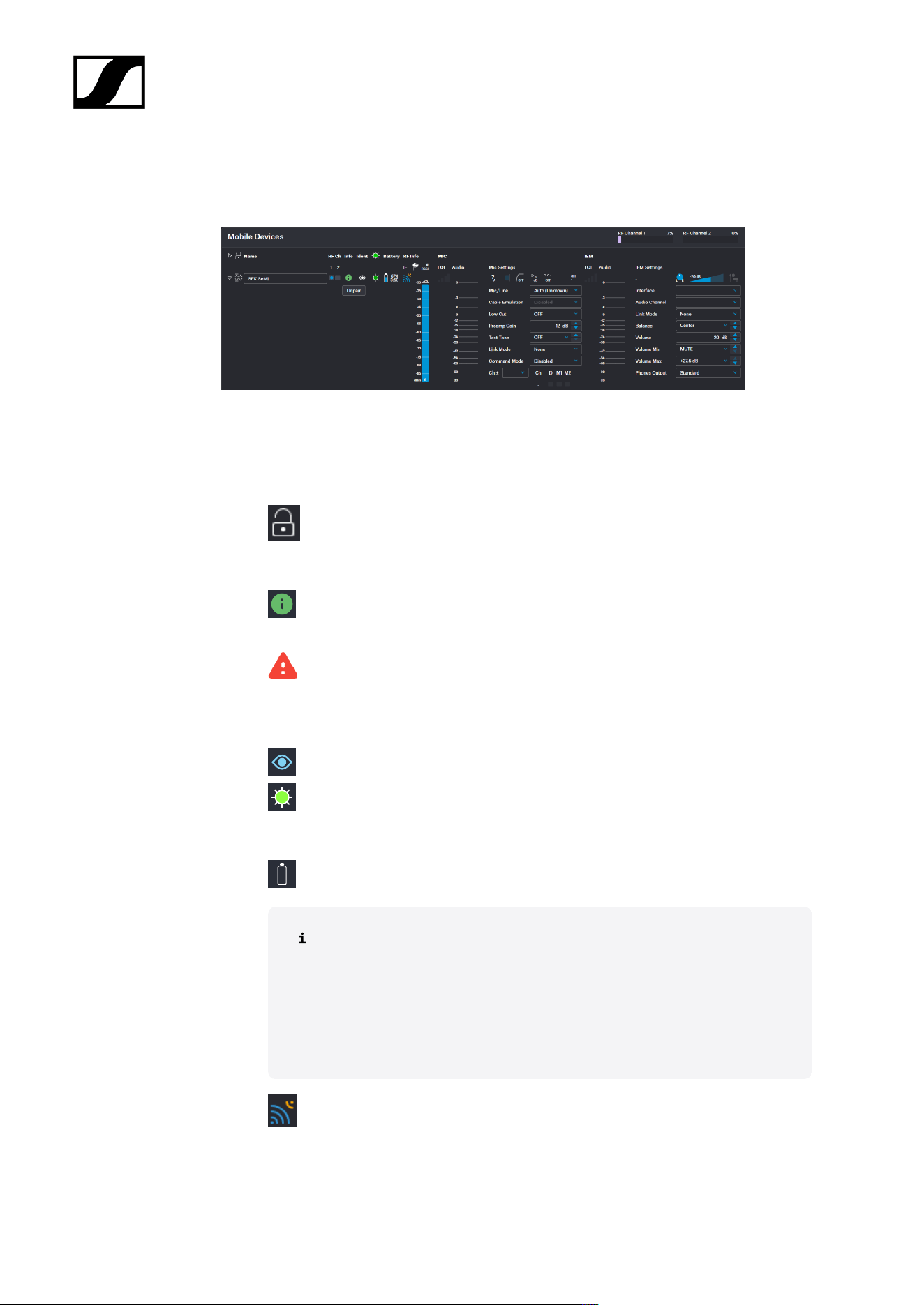
| 4 - Instruction manual
Mobile Devices
Here you can configure specific settings for mobile devices.
The following interactions can be made for each mobile device:
General
• Locking the sorting of mobile devices
• Changing the name of the device (see Changing the device name)
• Assigning an RF channel (see Assigning an RF channel)
• Monitoring the status of the device (connection status, temperature, entitlement,
data-transition etc).
red flashing, Warning: Firmware update not possible
• Hardware revision too old and not longer supported. OR
• Handware revision too new. Please update the Base Station firmware first. OR
• Battery too low. Please use a battery with higher fill level.
• Identifying the device (see Identifying your mobile device)
• Changing the LED color (see Changing the LED color, the top LED changes the
color for all mobile devices)
• Pairing/unpairing the device (see Pairing/unpairing mobile devices)
• Monitoring the battery status
The time specifications for hh:mm have a tolerance of ± 10 minutes. If the
battery shows < 10%, a lower battery level is displayed than is actually
still available.
The displayed time is an estimated remaining runtime based on current
power consumption. Different audio link modes, headphone types and
IEM volume can change this estimate.
• Interference level at mobile device
130
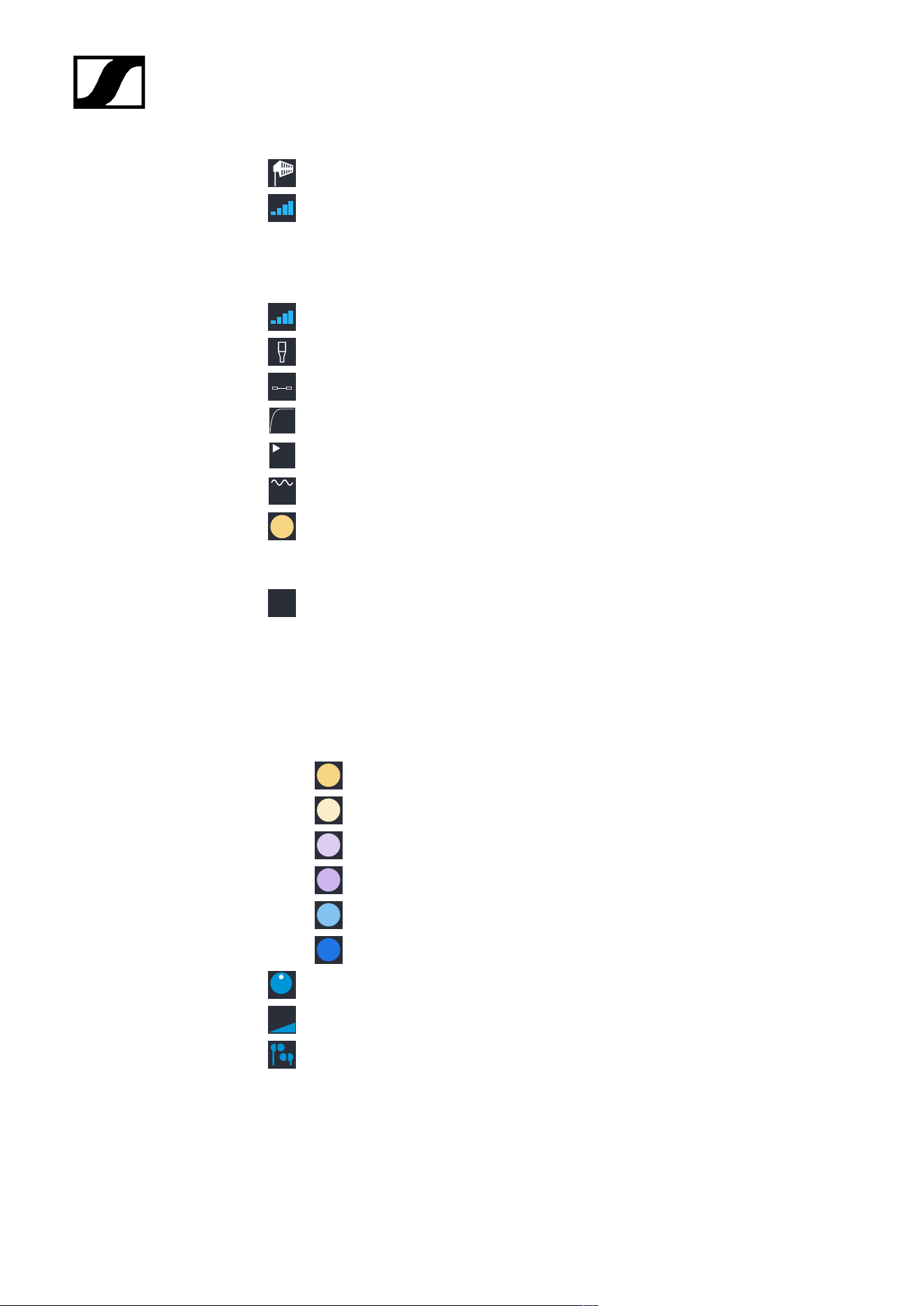
| 4 - Instruction manual
• Receive Single Strength Indication at the dominant antenna
• Link Quality Input (LQI)
MIC
• Link Quality Input (LQI) (see Selecting audio link mode (Mic/Line))
• Input Mic/Line (see Selecting the Mic/Line input)
• Cable Emulation (see Activating/deactivating cable emulation)
•
OFF
Low Cut (see Activating/deactivating Low Cut)
•
12
dB
Preamp Gain (see Setting the Preamp Gain)
•
OFF
Test Tone (see Activating/deactivating Test Tone)
• Link Mode (color depends on the mode) (see Selecting audio link mode (Mic/
Line))
• Command Mode (see Setting the command mode)
•
CH
1
Assigned channel (see Audio inputs and outputs)
In-Ear Monitoring (IEM)
• Interface (see Selecting the default audio input/output source)
• Audio Channel (see Selecting an audio channel (IEM link))
• Link Mode (see Selecting audio link mode (IEM))
• Max Range
• Max Link Density
• Live Link Density Range
• Live Link Density Range
• Live Low Latency
• Live Ultra Low Latency
•
L R
Balance / Center (see Adjusting the balance)
•
-34.5dB
Volume (see Setting the volume)
• Headphone
• Phones Output (see Selecting the phones output)
131
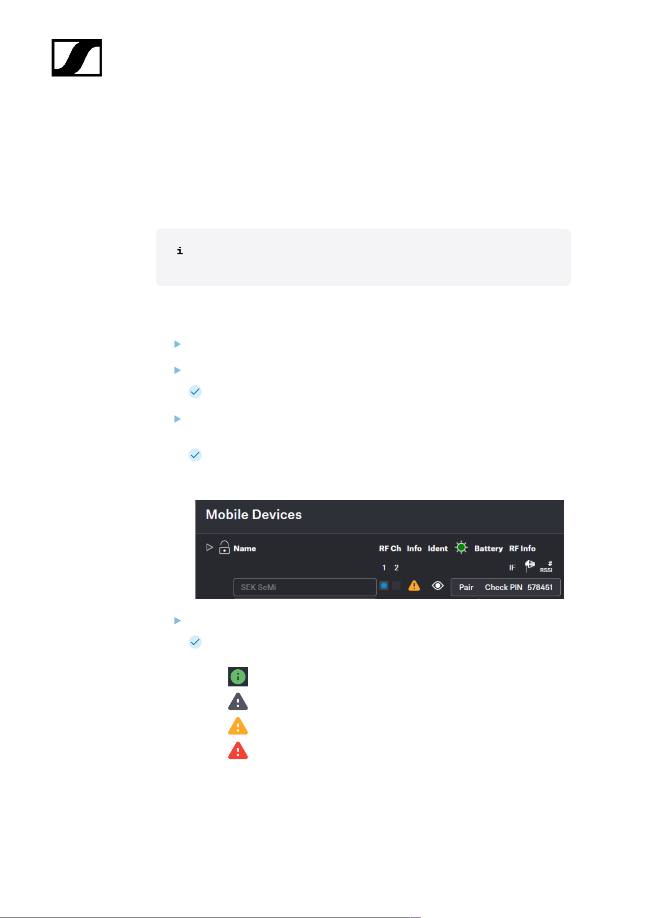
| 4 - Instruction manual
Pairing/unpairing mobile devices
In the WebUI, you can pair up to 128 mobile devices to a Base Station within one RF
channel.
Mobile devices can only be paired and operated with one Base Station at a time. If a mobile
device is to be used with another Base Station, it must first be paired again.
Please unmute at least one RF channel before pairing if this was not done
automatically.
To pair a mobile device:
In the top bar, navigate to Configuration > Base Station.
Click on Enable Pairing.
The Base Station starts the pairing process for 300 seconds.
Switch on your mobile device and activate Pairing Mode if it has not been activated
automatically (Switching the SEK on and off/Switching the SKM on and off).
After a few seconds, the available mobile devices are displayed in the list below
under Mobile Devices. A verification PIN is displayed on the mobile device and in
the WebUI.
Verify the PIN on the mobile device and click on Pair.
The mobile device has been paired successfully. The device state color changes
to:
• green (successfully paired)
• gray (assigned RF channel not on air)
• yellow (firmware mismatch) or
• red (unconnected, no RF channel selected, not available)
132

| 4 - Instruction manual
To unpair a mobile device:
To unpair a paired device, the audio links must first be deactivated.
In the top bar, navigate to Configuration > Mobile Devices.
Click on the button Unpair > Confirm in the line of the mobile device to be unpaired.
The mobile device has been successfully unpaired.
The mobile devices have been successfully paired/unpaired.
133

| 4 - Instruction manual
Identifying your mobile device
You can remotely identify your mobile device.
To identify the mobile device:
In the top bar, navigate to Configuration > Mobile Devices.
Click on the Identify icon.
The LED on the mobile device flashes white alternately for 5 seconds.
The mobile device has been identified.
134
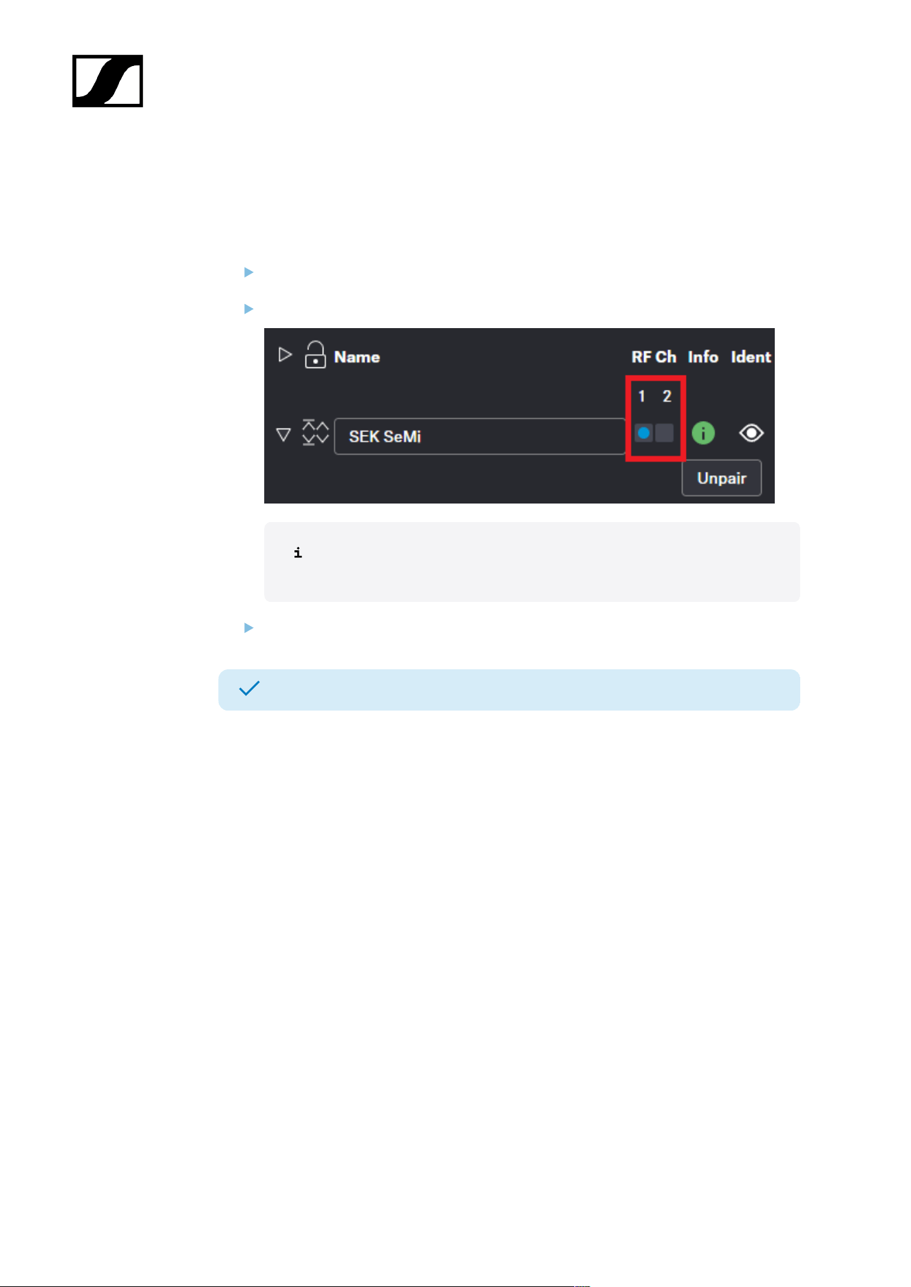
| 4 - Instruction manual
Assigning an RF channel
You can assign a configured RF channel to your mobile device.
To assign the RF channel:
In the top bar, navigate to Configuration > Mobile Devices.
Select your configured channel under RF Ch.
To change the RF channel, you must first deactivate the audio Link Mode
and the audio Channels.
Enable the toggle switch of the configured RF channel.
The RF channel has been assigned to your mobile device.
135
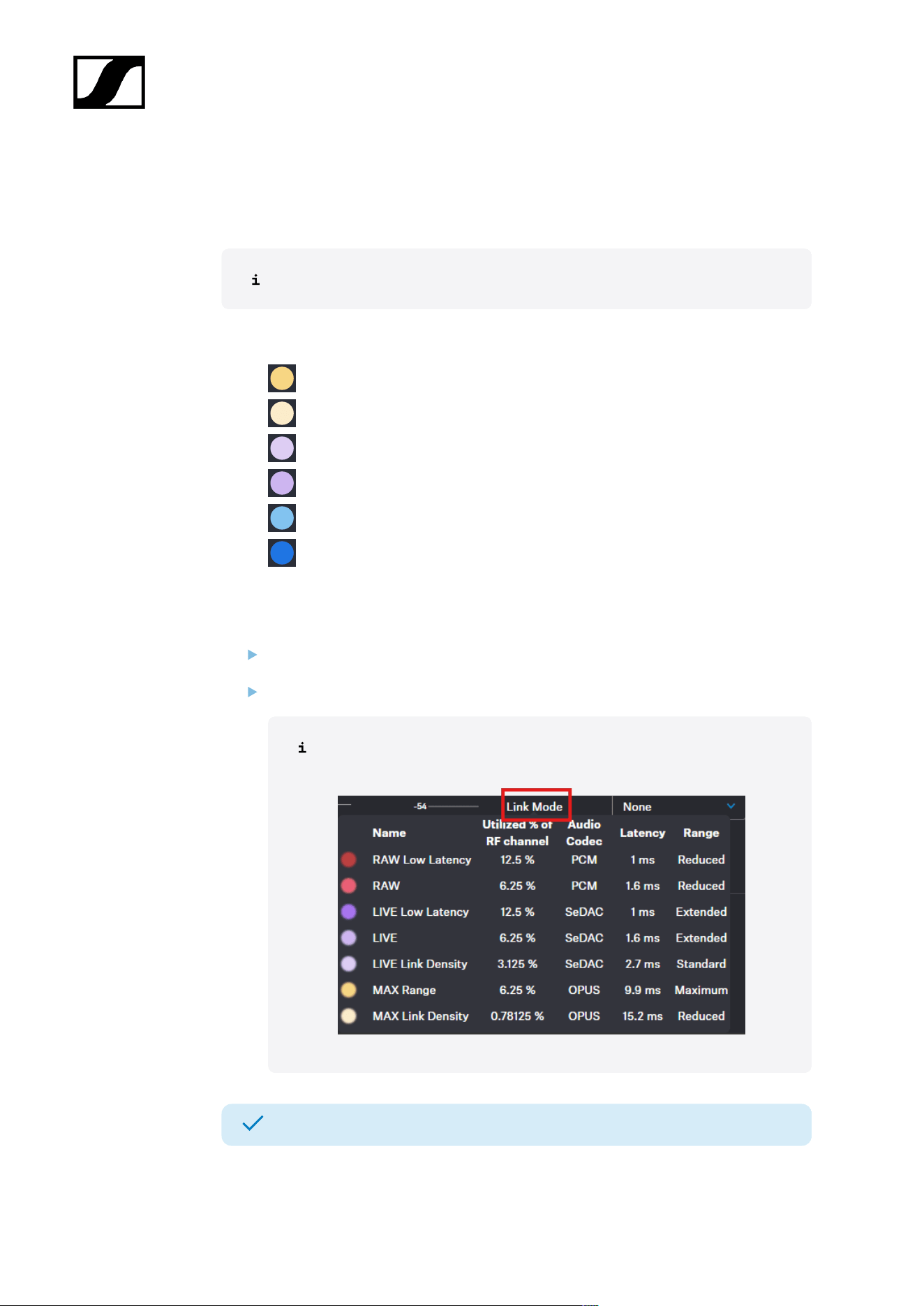
| 4 - Instruction manual
Selecting audio link mode (IEM)
You can select the audio mode for your IEM link.
Please note that the bandwidth utilization varies depending on the link mode.
The following modes are available:
• Max Range
• Max Link Density
• Live Link Density Range
• Live Link Density Range
• Live Low Latency
• Live Ultra Low Latency
To select the audio mode:
In the top bar, navigate to Configuration > Mobile Devices > IEM Settings.
Select the audio mode from the drop-down list Link Mode.
Hover your mouse over the word Link Mode to display a tabular listing
of possible modes.
The audio mode has been selected.
136
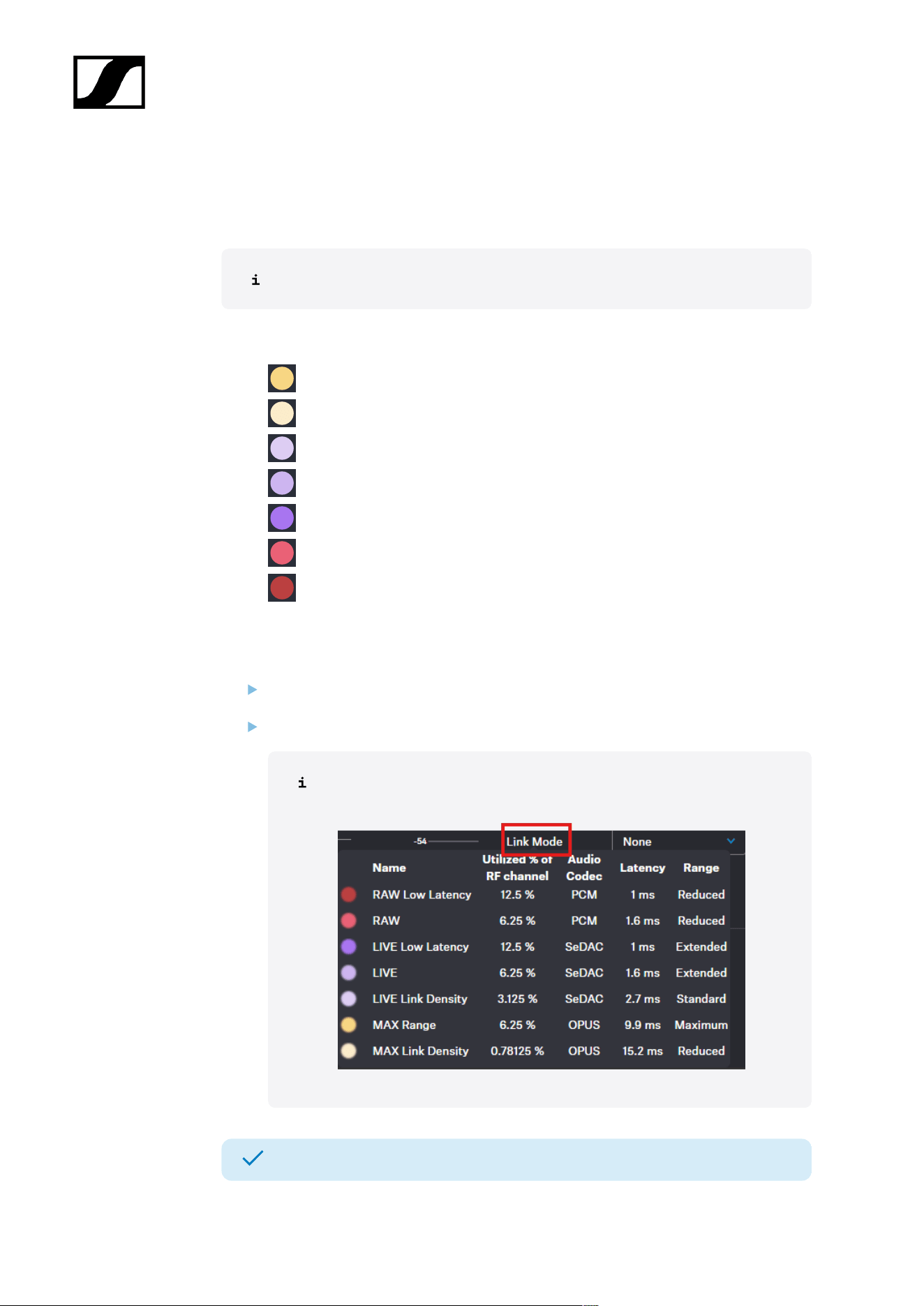
| 4 - Instruction manual
Selecting audio link mode (Mic/Line)
You can select the audio mode for your Mic/Line link.
Please note that the bandwidth utilization varies depending on the link mode.
The following modes are available:
• Max Range
• Max Link Density
• Live Link Density
• LIVE
• Live Low Latency
• RAW
• RAW Live Low Latency
To select the audio mode:
In the top bar, navigate to Configuration > Mobile Devices > Mic Settings.
Select the audio mode from the drop-down list Link Mode.
Hover your mouse over the word Link Mode to display a tabular listing
of possible modes.
The audio mode has been selected.
137
| 4 - Instruction manual
Selecting the Mic/Line input
You can select the audio input as the signal source for your Mic/Line link.
For a smooth system configuration, we recommend first selecting the link modes
and afterwards assigning the channels:
• Selecting audio link mode (Mic/Line)
• Selecting audio link mode (IEM)
• Adding/removing an audio channel (Mic/Line)
• Selecting an audio channel (IEM link)
• Selecting the IEM audio interface
You can route audio links to several channels. Routing can be performed easily
via the routing matrix (see Audio inputs and outputs).
The following input signals are available:
• Auto (unknown)
• Mic
• Line
The automatic mic/line detection is based on power consumption and
is optimized for use with Sennheiser microphones. Because third‑party
microphones vary widely, reliable detection cannot always be ensured.
To choose the audio input:
In the top bar, navigate to Configuration > Mobile Devices > Mic Settings.
Select the audio input from the drop-down list Mic/Line.
The audio input has been selected.
138

| 4 - Instruction manual
Adding/removing an audio channel (Mic/Line)
You can assign an audio channel number and the interface output for your Mic/Line link.
You can route audio links to several channels. Routing can be performed easily
via the routing matrix (see Audio inputs and outputs).
To add an audio channel:
In the top bar, navigate to Configuration > Mobile Devices > Mic Settings.
Select the channel number from the drop-down list Channel which is indicated with a
plus in front of it (e.g. +1).
To remove the link channel:
Select the channel number from the drop-down list Channel which is indicated with a
minus in front of it (e.g. -1).
To select the output interface of the assigned link channel:
Activate/deactivate the check-boxes under D (for DANTE®), M1 (for MADI 1) and/or
M2 (for MADI 2).
The audio channel and the audio interface output has been added/removed.
139

| 4 - Instruction manual
Changing the device name
You can change the device name for your mobile device.
For security reasons, please do not enter any sensitive personal data as the
device name.
To change the device name:
In the top bar, navigate to Configuration > Mobile Devices.
Edit the name under Name and confirm with ENTER.
The name is immediately transmitted to the mobile device and saved.
The device name has been changed.
140
| 4 - Instruction manual
Changing the LED color
You can select the connected state color of your LED on the mobile device.
To change the LED color for all mobile devices:
Click on the on the top to change the LED color for all mobile devices.
There are five settings for the LED:
• OFF
• Dim
• Standard
• Bright
• Individual
To change the LED color for one mobile device:
In the top bar, navigate to Configuration > Mobile Devices.
Click on the icon to change the LED color.
A menu with pre-selected colors opens.
Select a pre-selected color.
OR
141
| 4 - Instruction manual
Select an individual color.
The LED color has been changed.
If you reset the Base Station, all LED color settings are reset to their default values.
142

| 4 - Instruction manual
Selecting the IEM audio interface
You can select the desired audio interface as the signal source for your IEM link.
The following interfaces are available:
• Dante®
• MADI 1
• MADI 2
To choose the audio interface:
In the top bar, navigate to Configuration > Mobile Devices > IEM Settings.
Select the audio interface from the drop-down list Interface.
The audio interface has been selected.
143
| 4 - Instruction manual
Selecting an audio channel (IEM link)
You can assign an audio channel number for your IEM link.
For a smooth system configuration, we recommend first selecting the link modes
and afterwards assigning the channels:
• Selecting audio link mode (Mic/Line)
• Selecting audio link mode (IEM)
• Adding/removing an audio channel (Mic/Line)
• Selecting an audio channel (IEM link)
• Selecting the IEM audio interface
It is also possible to select an existing link (marked with *), as long as it is using
the same RF channel.
To add an audio channel:
In the top bar, navigate to Configuration > Mobile Devices > IEM Settings.
Select the channel number from the drop-down list Audio Channel.
The audio channel has been selected.
144

| 4 - Instruction manual
Adjusting the balance
You can change the balance for your IEM link.
The following values can be selected directly and adjusted individually in steps of 1%:
• 100% Left
• 75% Left
• 50% Left
• 25% Left
• Center
• 25% Right
• 50% Right
• 75% Right
• 100% Right
To change the balance:
In the top bar, navigate to Configuration > Mobile Devices > IEM Settings.
Select the balance mode from the drop-down list Balance.
The balance mode has been changed.
145
| 4 - Instruction manual
Setting the volume
The volume can be controlled directly from the device as well as from the WebUI.
If the volume value is changed on the device, this change is displayed in the WebUI in real
time.
WARNING
Hearing damage due to high volumes
This product is capable of producing sound pressure levels exceeding 85
dB (A). Volume levels that are too high may damage your hearing.
Reduce the volume and the microphone amplification, if
applicable, before using the product.
To set the volume:
In the top bar, navigate to Configuration > Mobile Devices > IEM Settings.
Enter the desired volume level in dB under Volume.
The volume has been set.
146
| 4 - Instruction manual
Setting the min volume
You can set a predefined min volume for your IEM link.
The volume set here is the minimum level that is sent to your dedicated mobile device.
The following values can be selected directly and adjusted individually in steps of 0.5 dB:
• -6 dB
• -12 dB
• -18 dB
• -24 dB
• -30 dB
• -36 dB
• -42 dB
• -48 dB
• -54 dB
• -60 dB
• MUTE
WARNING
Hearing damage due to high volumes
This product is capable of producing sound pressure levels exceeding 85
dB (A). Volume levels that are too high may damage your hearing.
Reduce the volume and the microphone amplification, if
applicable, before using the product.
To set the min volume:
In the top bar, navigate to Configuration > Mobile Devices > IEM Settings.
Select the min volume level in dB under Volume min.
The min volume has been set.
147
| 4 - Instruction manual
Setting the max volume
You can set a predefined max volume for your IEM link.
The volume set here is the maximum level that is transmitted to your connected mobile
device.
The following values can be selected directly and adjusted individually in steps of 0.5 dB:
• -27.5 dB
• -24 dB
• -18 dB
• -12 dB
• -6 dB
• 0 dB
• +6 dB
• +12 dB
• +18 dB
• +24 dB
• +27.5 dB
WARNING
Hearing damage due to high volumes
This product is capable of producing sound pressure levels exceeding 85
dB (A). Volume levels that are too high may damage your hearing.
Reduce the volume and the microphone amplification, if
applicable, before using the product.
To set the max volume:
In the top bar, navigate to Configuration > Mobile Devices > IEM Settings.
Select the max volume level in dB under Volume max.
The max volume has been set.
148
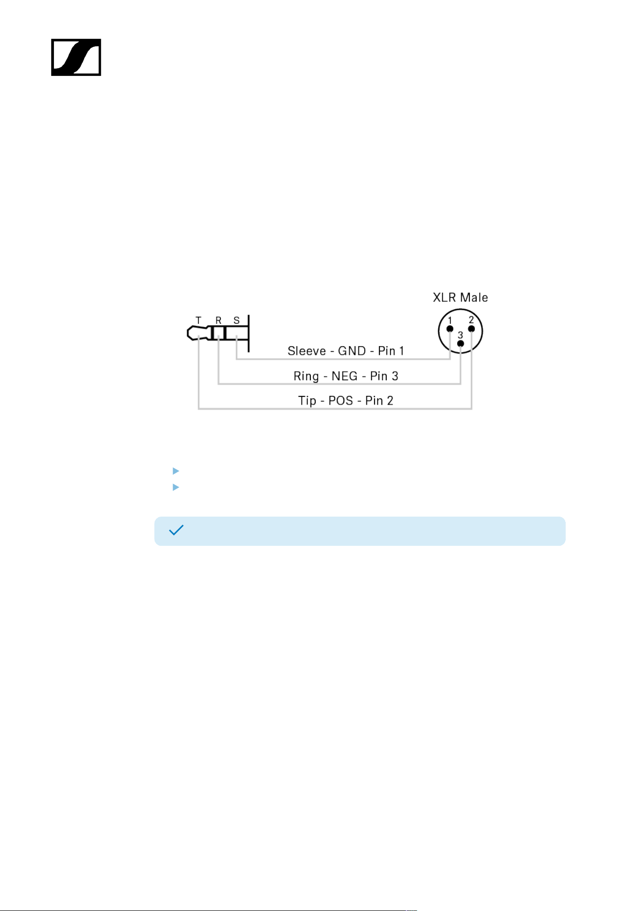
| 4 - Instruction manual
Selecting the phones output
Selecting the output for the PHONES socket of the mobile device.
The following outputs are available:
• Standard: Unbalanced mono or stereo phones output.
• Balanced: Enables right channel inversion for mono link modes.
The 'Balance' setting is disabled in this mode.
With this setting, for example, a cable with the following pinout can be used to
connect the phones output to a balanced line input.
To choose the phone output:
In the top bar, navigate to Configuration > Mobile Devices > IEM Settings.
Select the phone output from the drop-down list Phones Output.
The phones output has been selected.
149
| 4 - Instruction manual
Activating/deactivating cable emulation
You can emulate the capacitance of the connected instrument cable and influence the
sound of your mic/line input.
Cable emulation is only applicable when line input is selected.
The following presets are available:
• OFF
• Short
• Mid
• Long
To activate cable emulation:
In the top bar, navigate to Configuration > Mobile Devices > Mic Settings.
Select the value Line from the audio input list.
Select the value from the drop-down list Cable Emulation.
To deactivate cable emulation:
Select the value OFF.
The cable emulation value has been activated/deactivated.
150

| 4 - Instruction manual
Activating/deactivating Low Cut
You can reduce or remove low frequencies in the audio signal while allowing high
frequencies to pass through.
This allows low-frequency ambient noise to be filtered out of the audio signal, thereby
improving the clarity of the audio.
The following presets are available:
• OFF
• 30 Hz
• 60 Hz
• 80 Hz
• 100 Hz
• 120 Hz
To activate Low Cut:
In the top bar, navigate to Configuration > Mobile Devices > Mic Settings.
Select the value from the drop-down list Low Cut.
To deactivate Low Cut:
Select the value OFF.
Low Cut has been activated/deactivated.
151

| 4 - Instruction manual
Setting the Preamp Gain
With the preamp you can increase the audio level for your Mic/Line output.
To set the gain:
In the top bar, navigate to Configuration > Mobile Devices > Mic Settings.
Enter the desired preamp gain level in 1 dB increments under Preamp Gain.
The Preamp Gain has been set.
152

| 4 - Instruction manual
Activating/deactivating Test Tone
With a constant test tone, you can simulate and test the performance of your audio devices
in different dB levels.
The following values can be selected directly and adjusted individually in steps of 1 dB:
• OFF
• -60 dB
• -54 dB
• -48 dB
• -42 dB
• -36 dB
• -30 dB
• -24 dB
• -18 dB
• -12 dB
• -6 dB
• 0 dB
To activate the Test Tone:
In the top bar, navigate to Configuration > Mobile Devices > Mic Settings.
Select the value from the drop-down list under Test Tone.
To deactivate the Test Tone:
Select the value OFF.
The Test Tone has been activated/deactivated.
153
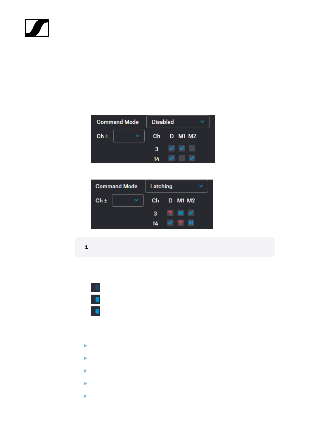
| 4 - Instruction manual
Setting the command mode
You can set the command mode for the COM button.
The settings of the selected audio output channels can vary whether the command mode is
active or inactive.
• Command mode disabled:
• Command mode enabled:
This option is only available if Mic is selected as the audio input.
The following options are available separately for each selected audio output channel on the
Base Station individually:
• Disabled - audio is either on or off
• Momentary - hold down the COM button
• Latching - press the COM button to change the state
To set a command mode:
In the top bar, navigate to Configuration > Mobile Devices > Mic Settings.
Select the value Mic from the audio input list.
Select the audio mode from the drop-down list Link Mode.
Select an audio channel from the drop-down list Ch ±.
Select the mode from the drop-down list Command Mode.
154
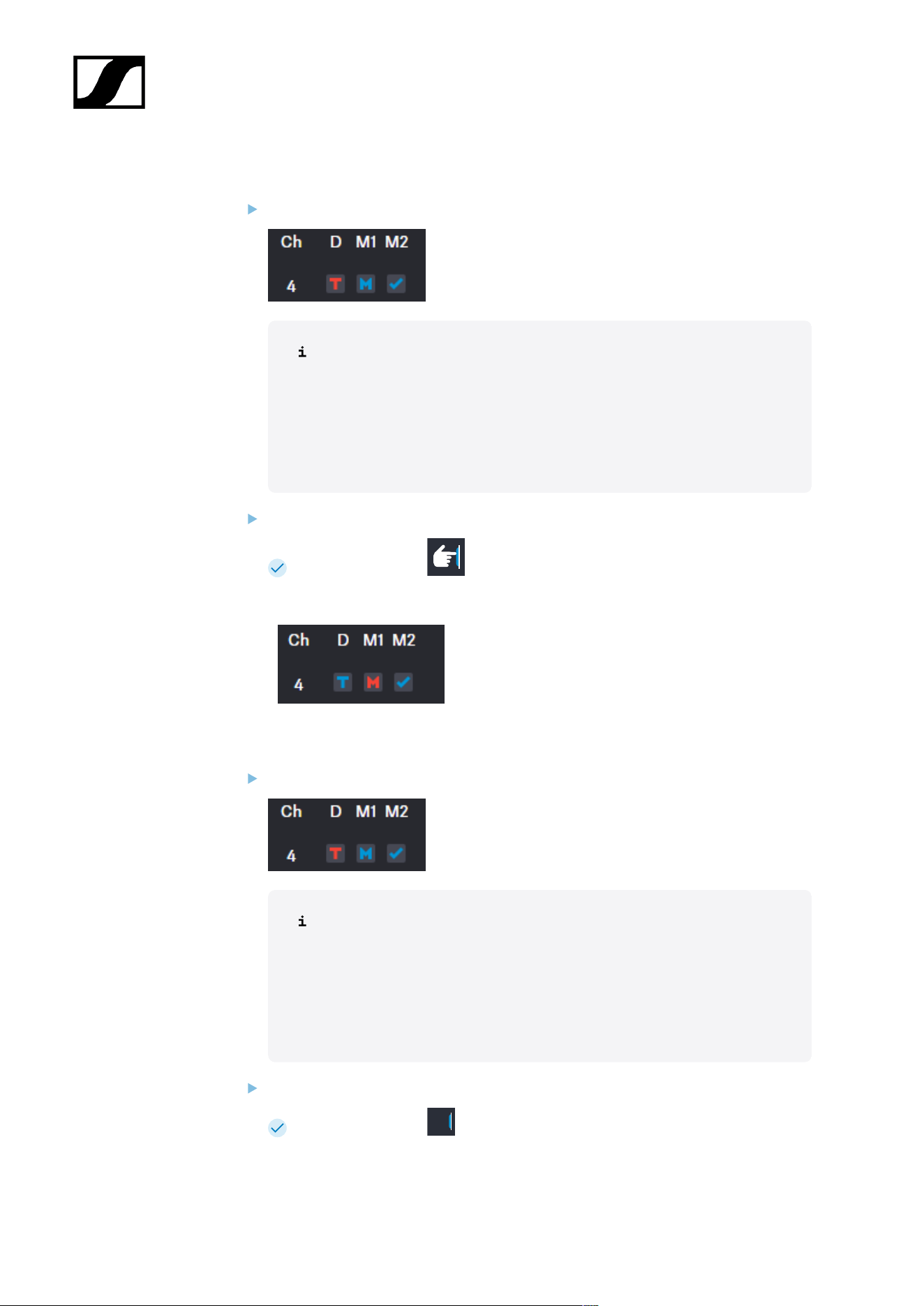
| 4 - Instruction manual
If you selected Momentary:
Set the options for the audio channel by clicking in the boxes.
Meaning of the letters and colors:
T = talk
M = mute
red = audio inactive
blue = audio active
Hold down the COM button.
The icon changes to .
The audio transmission changes:
If you selected Latching:
Set the options for the audio channel by clicking in the boxes.
Meaning of the letters and colors:
T = talk
M = mute
red = audio inactive
blue = audio active
Press the COM button.
The icon changes to .
155
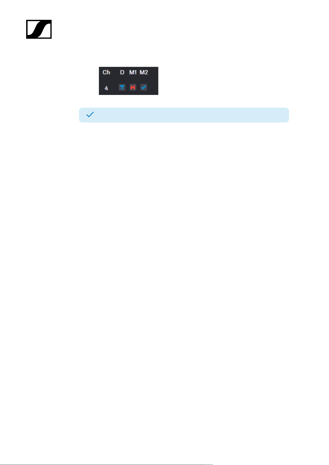
| 4 - Instruction manual
The audio transmission changes:
The command mode has been set.
If the mobile device is turned off or the antenna is muted, the color of the settings changes to
blue.
156
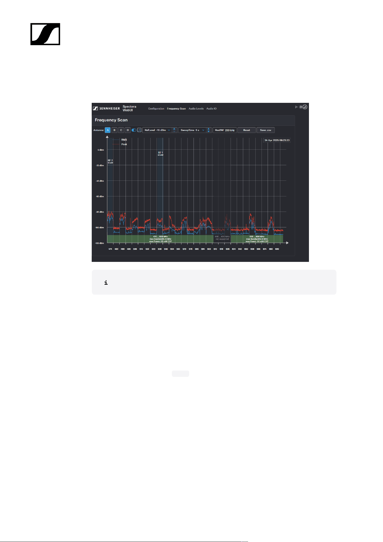
| 4 - Instruction manual
Frequency Scan
You can use an RF scan to examine the current frequency situation of your connected
antenna.
Make sure that no antenna is activated!
You can monitor and control the following settings in the Frequency Scan menu:
• Selecting the antenna (A-D) connected to the Base Station
• Setting the RefLevel (reference level for frequency scan)
• Setting the Sweep time for frequency scan between 2s (fast update rate) and 60s
(slow update rate)
• Setting the resolution bandwidth
• Resetting the peak trace
• Saving all settings to a .csv file
Scanning the RF frequency
You can run a frequency scan to check the current frequency situation in your surrounding
area.
The frequency scan provides an overview of the frequency situation in your location. You can
save the antenna configuration as a .csv info file. This file can be used as a backup file to
recapitulate your settings or as local frequency information for your specific environment.
You can scan the frequencies of all antennas connected to the Base Station.
157
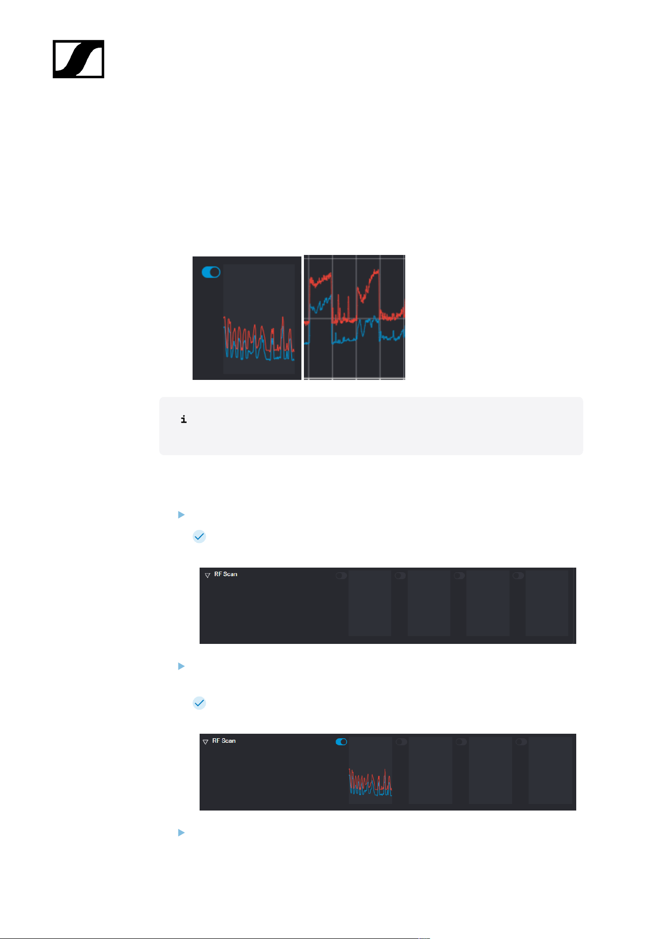
| 4 - Instruction manual
The scan can be initiated:
• via the RF configuration tab to see a small extract without any details or
• via the Frequency Scan tab for a detailed overview of the frequency situation.
The scan results will be displayed in two different curves:
• Peak (red) = Maximum value
• RMS (blue) = Average power or strength
Please note that the antenna must not be assigned to an RF channel before
scanning (see Assigning an antenna to an RF channel).
To scan the RF frequency via the RF configuration tab:
In the top bar, navigate to Configuration > RF Configuration.
Under the RF Scan drop-down menu, there are four toggle switches that enable
and disable the scan function for each connected antenna.
Click on the toggle switch of the antenna to be scanned in order to start an immediate
scan.
The square is highlighted with a blue dot and the scan result is displayed in a
small frequency curve after approx. 5 seconds.
In order to view the results,
158
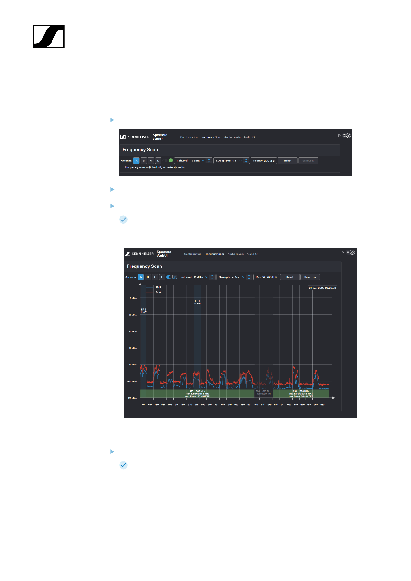
| 4 - Instruction manual
• click on the small frequency icon or
• navigate to Frequency Scan in the top bar.
To scan the RF frequency via the Frequency Scan tab:
In the top bar, navigate to the tab Frequency Scan.
Select your antenna to be scanned and adjust your desired settings.
Switch on the toggle to start the scan.
The frequency scan is started and the result is displayed in a detailed frequency
diagram. Supported frequency ranges are shown in green and unsupported
ranges in gray.
To reset a scan:
Click on Reset.
The current scan will be reset.
159
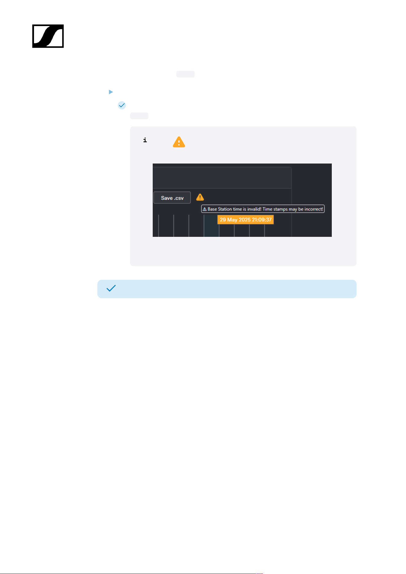
| 4 - Instruction manual
To save the scan results as .csv :
Click on Save.csv.
The antenna configuration has been downloaded locally to your computer as a
.csv file.
If a appears after Save.csv, the time on the Base Station is
invalid.
Connect the Base Station to the Internet to get the correct time.
The frequency of your connected antenna has been scanned.
160
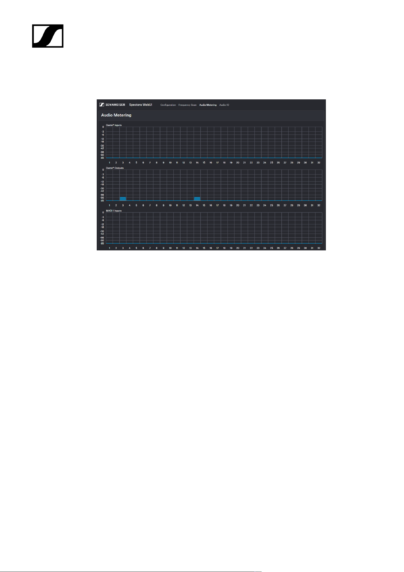
| 4 - Instruction manual
Audio Metering
Under Audio Metering you can monitor all interfaces at a glance.
All interfaces are sorted according to their inputs and outputs and displayed visually with a
frequency response:
• Dante® Inputs
• Dante® Outputs
• MADI 1 Inputs
• MADI 1 Outputs
• MADI 2 Inputs
• MADI 2 Outputs
161
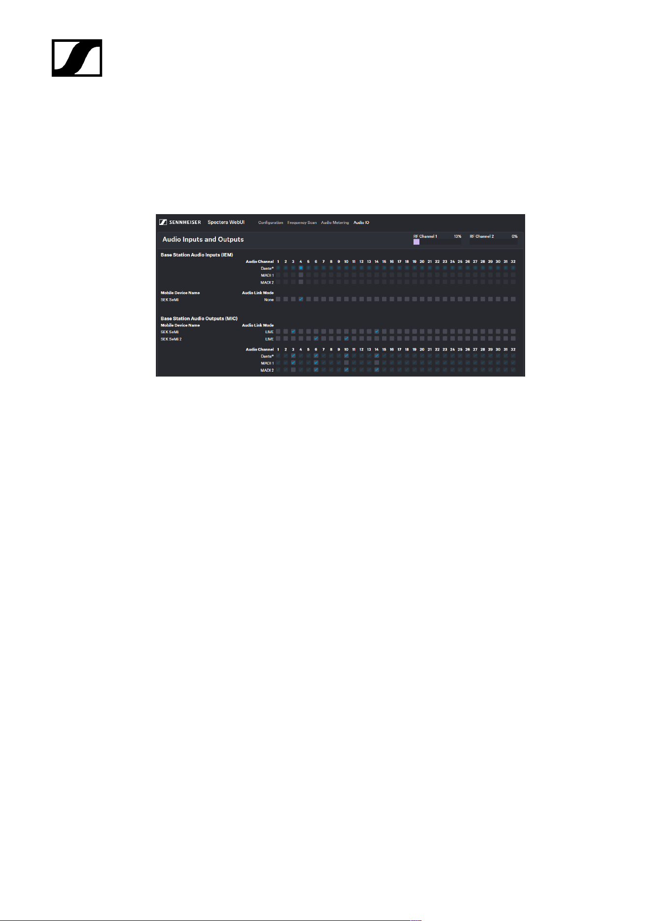
| 4 - Instruction manual
Audio inputs and outputs
Here you have an overview of all channels at a glance and can assign the audio network
input and output for the link channels directly and easily.
The link modes assigned in the mobile devices are displayed here. You can select the desired
channels directly and assign them to your audio network input or output.
162
| 4 - Instruction manual
Changing the device password
You have two options to change the device password on your Base Station.
You have two options:
• Change the password before logging in.
• Change or reset the password by resetting the device to factory settings.
To change or reset the device password, the device must be reset to factory
settings.
NOTICE
Data loss during the factory reset
All audio devices will be unpaired and all audio routes will be deleted.
All settings (including the device password) are reset to the default
values. The license remains activated.
After the reset, the device is restarted automatically.
Do not reset the Base Station during an active live audio
transmission.
To reset the password to factory settings, you have two options available:
• Reset via the device (see Reset)
• Reset via the WebUI interface (see Resetting the Base Station)
To change the password:
Enter the following URL into your browser: https://deviceIP/specterawebui/
index.html .
Since the certificate is unknown to your browser, a security warning is
displayed the first time you run the application. The security warning
depends on the browser you are using.
Click on Change.
163
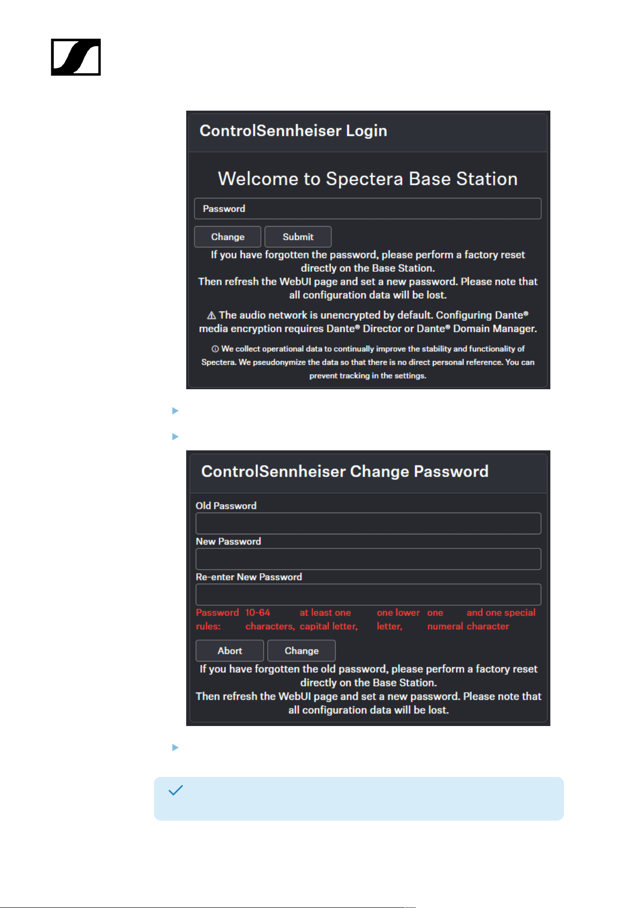
| 4 - Instruction manual
Enter the old password.
Enter the new password two times.
Click on Change to save the new password or click on Abort to cancel the change.
The password has been changed or the Base Station has been reset to its factory
default settings.
164
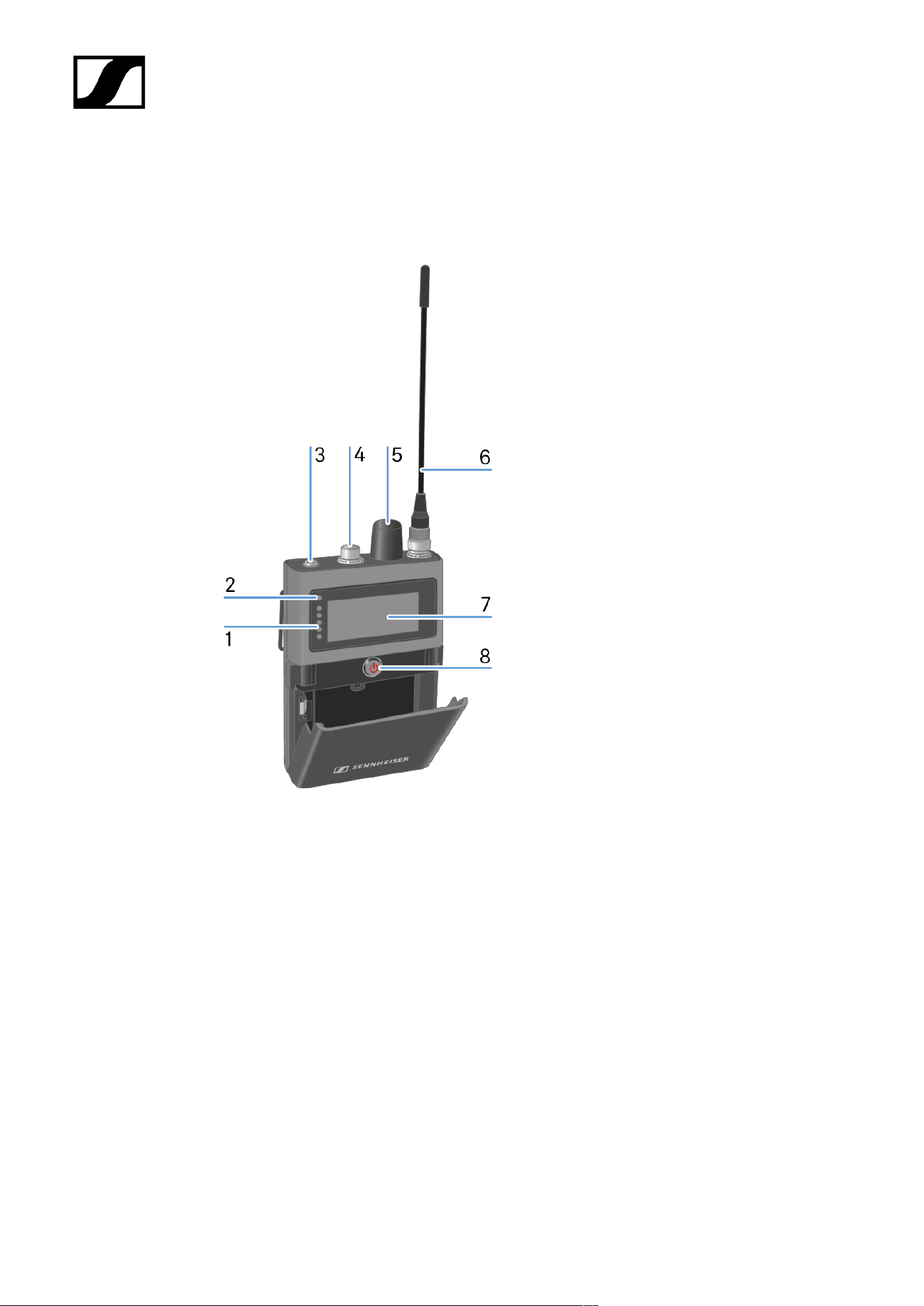
| 4 - Instruction manual
SEK
Product overview
1 LEDs
see Meaning of the LEDs
2 Status LED
see Meaning of the LEDs
3 Phones 3.5 mm jack
see To use the Phones jack
4 Microphone / Instrument input
see Connecting a microphone / instrument
see Connecting the COM Button
5 Rotary encoder
with push function
see Information on the display
165

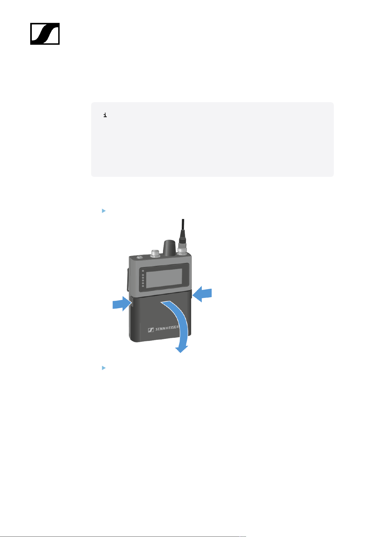
| 4 - Instruction manual
Inserting and removing the rechargeable battery
The SEK operates only with the recharable battery BA 70 (seperate accessory).
The BA 70 can be charged in the L 70 USB, the L 6000 with LM 6070 or with
the SEK in the CHG 70N-C.
• L 70 USB: Charging the rechargeable battery
• L 6000: Charging the rechargeable batteries in the L 6000 charger
• CHG 70N-C: Charging the rechargeable battery
To insert the recharable battery into the SEK:
Press the two catches and open the battery compartment cover.
Insert the BA 70 rechargeable battery in the battery compartment.
167
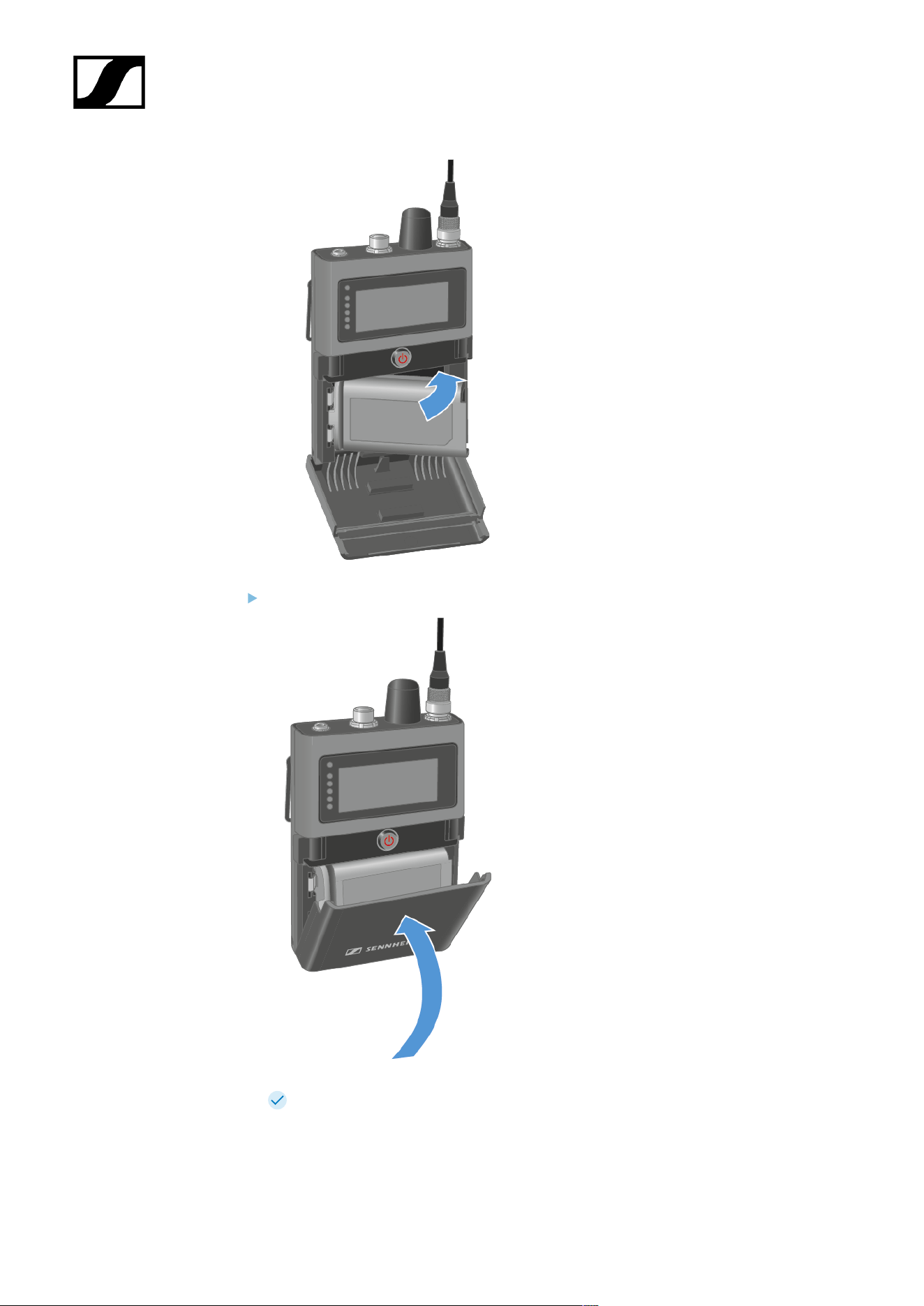
| 4 - Instruction manual
Close the battery compartment.
The cover locks into place with an audible click.
168

| 4 - Instruction manual
The battery has been inserted.
169
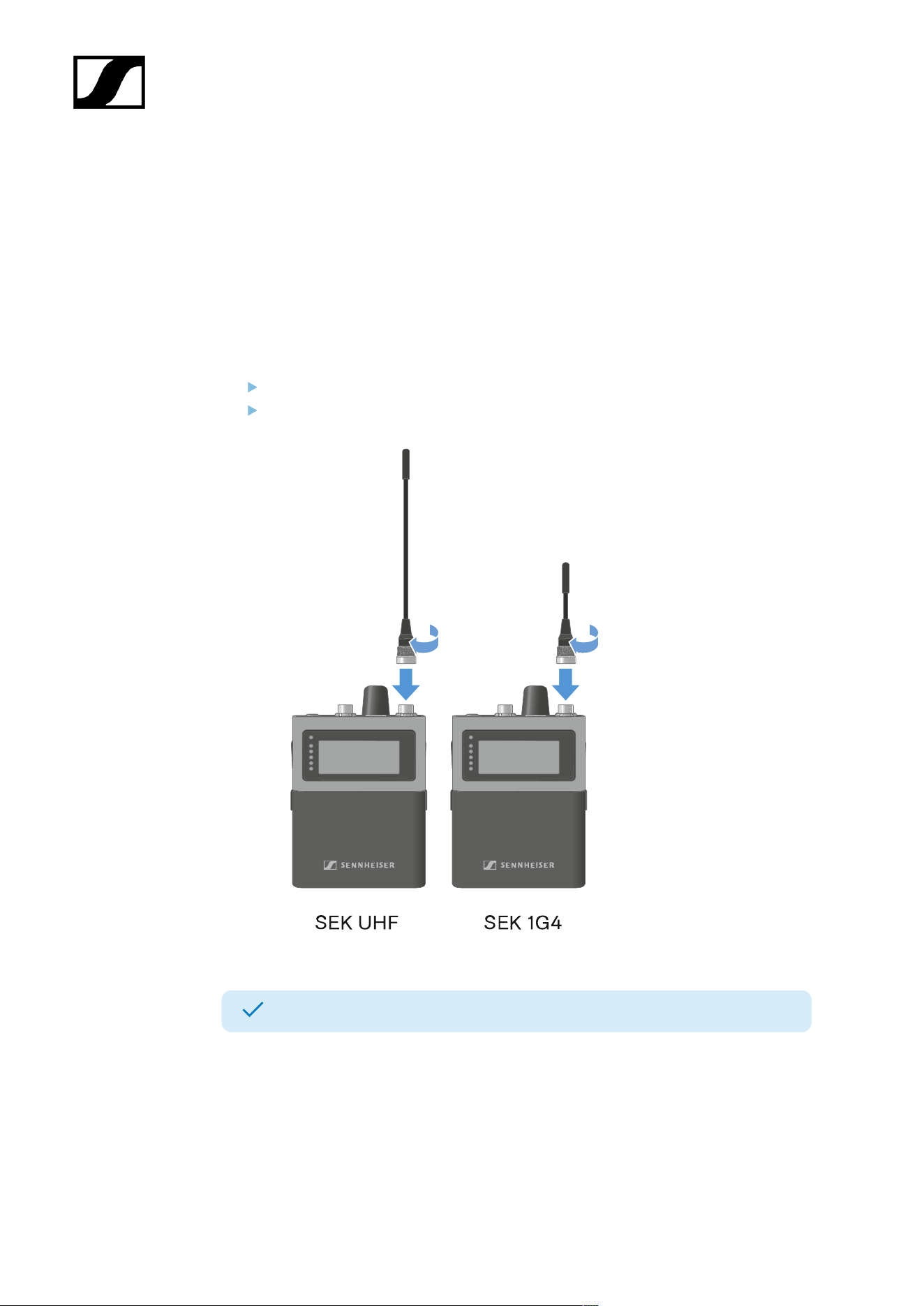
| 4 - Instruction manual
Mounting the antenna
Two antennas are available, one for each frequency range.
For more information see Spectera SEK Antenna.
The antenna is screwed on when it is delivered.
To mount the antenna to the SEK:
Connect the antenna to the SEK antenna socket.
Tightly screw the antenna coupling ring onto the SEK antenna socket.
The antenna has been mounted.
170
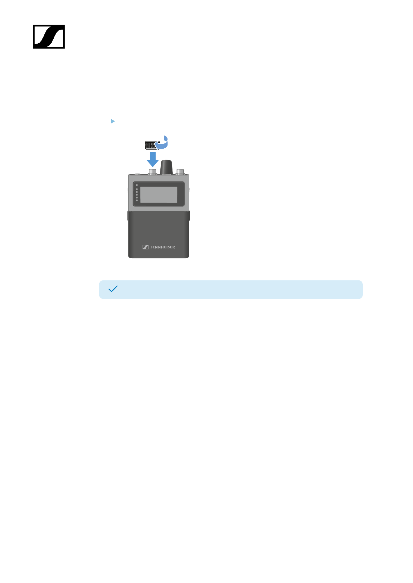
| 4 - Instruction manual
Using the protection cap
The cap protects the microphone / instrument input, when not in use.
To screw the cap on the SEK:
Screw the cap on the microphone / instrument input socket.
The cap has been attached.
171
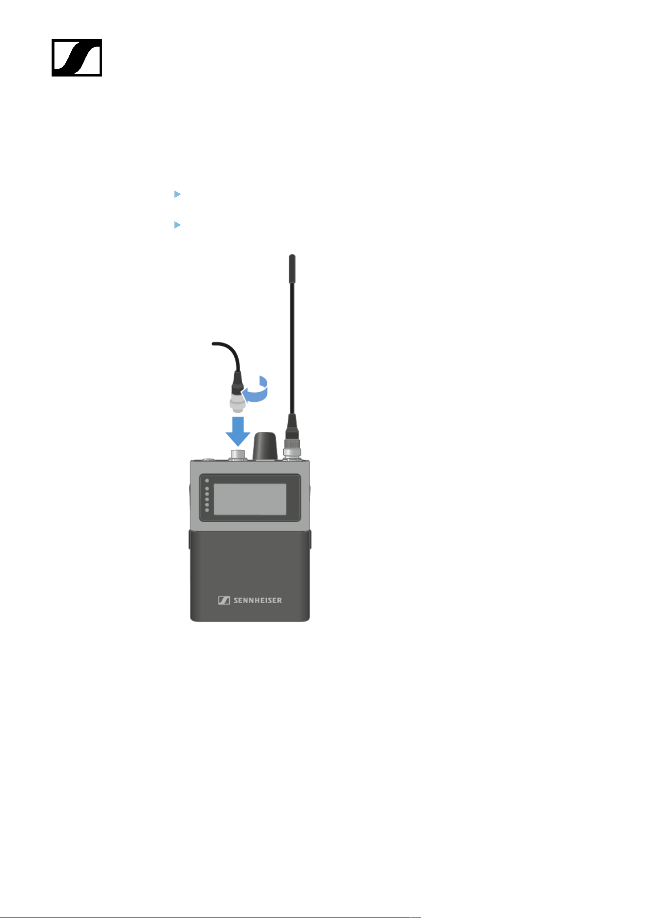
| 4 - Instruction manual
Connecting a microphone / instrument
You can connect a microphone or instrument to the SEK.
To connect a microphone to the SEK:
Use a 3-pin audio connector to connect the microphone cable to the SEK
microphone / instrument input socket.
Screw the plug’s coupling ring onto the microphone / instrument input thread of the
SEK.
172
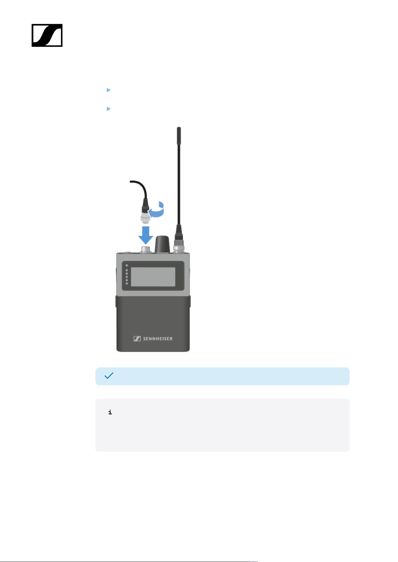
| 4 - Instruction manual
To connect a instrument to the SEK:
Use a 3-pin audio connector to connect the instrument cable to the SEK microphone /
instrument input socket.
Screw the plug’s coupling ring onto the microphone / instrument input thread of the
SEK.
A microphone or instrument has been connected.
The automatic mic/line detection is based on power consumption and
is optimized for use with Sennheiser microphones. Because third‑party
microphones vary widely, reliable detection cannot always be ensured. To select
the auto input manually, see Selecting the Mic/Line input.
The following microphones are compatible:
• Headmic 1 (3-Pin) | Headset microphone with omni-directional pattern
• Headmic 4 (3-Pin) | Headset microphone with cardioid pattern
• HM 200 (3-Pin) | Headset microphone with omni-directional pattern
• HSP 2 (3-Pin) | Headset microphone with omni-directional pattern
173

| 4 - Instruction manual
• HSP 4 (3-Pin) | Headset microphone with cardioid pattern
• ME 102 (3-Pin) | Mini-microphone with omni-directional pattern
• MKE 1 (3-Pin) | Lavalier microphone with omni-directional pattern
• MKE 2 (3-Pin) blue label | Lavalier microphone with omni-directional pattern
• MKE 40 (3-Pin) | Lavalier microphone with cardioid pattern
• MKE Essential (3-Pin) | Lavalier microphone with omni-directional pattern
174
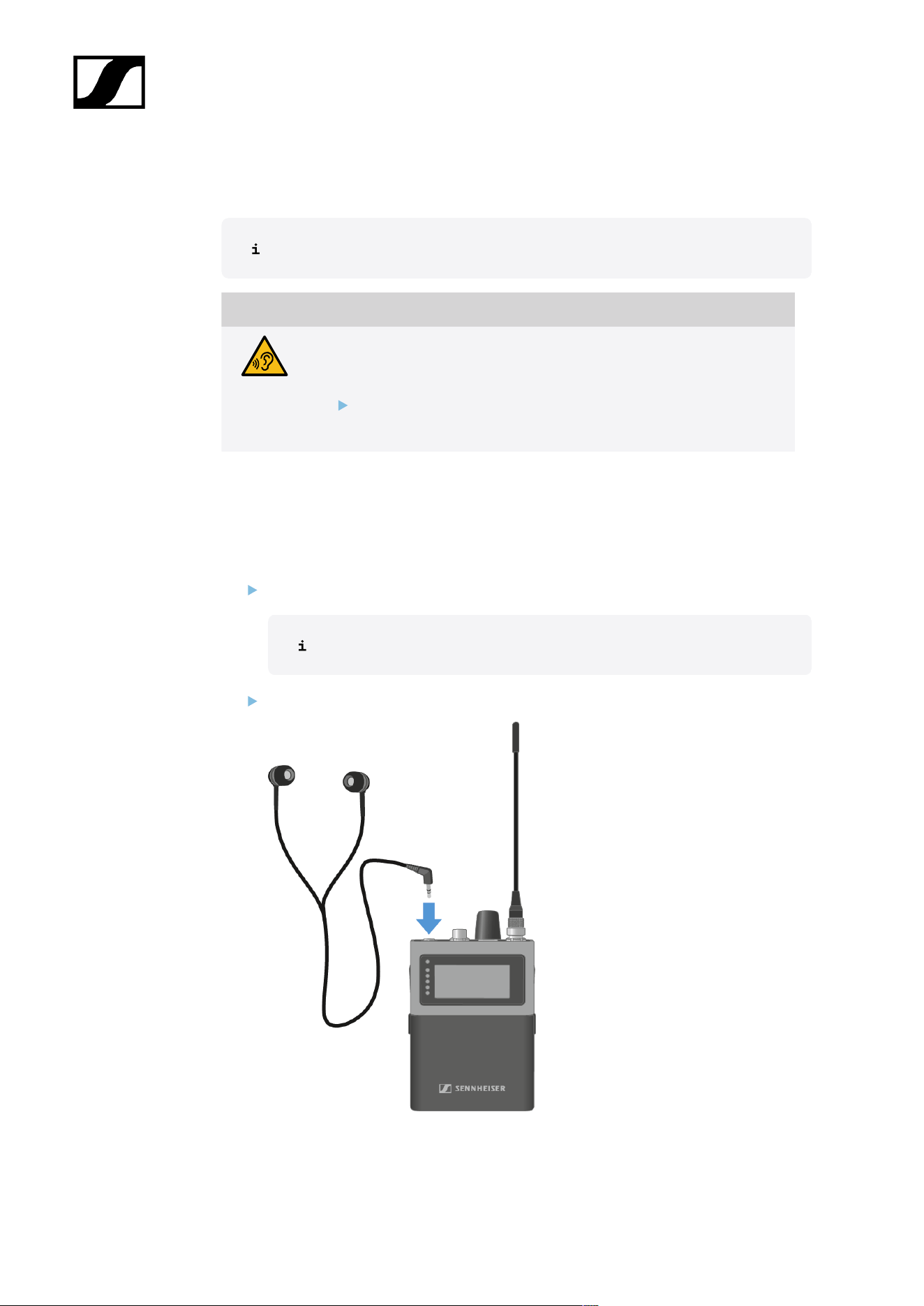
| 4 - Instruction manual
To use the Phones jack
You have to set up an audio link in Spectera WebUI.
CAUTION
Danger due to high volume levels
Volume levels that are too high may damage your hearing.
Turn down the volume of the headphone output before you put on
the headphone.
The SEK checks the headphone's impedance when a headphone is plugged in at switching
on, or each time a headphone is newly plugged in.
To connect earphones to the SEK:
Turn down the volume.
The volume can be altered between -100 dB to +27.5 dB in steps of 0.5 dB.
Insert the cable’s 3.5 mm jack plug into the phones socket on the SEK.
175

| 4 - Instruction manual
To connect an adapter cable:
Insert the 3.5 mm jack plug of the cable into the Phones jack on the SEK.
Connect the other plug to the desired device.
In the WebUI, set the Phones Output to Balanced, see Selecting the phones output.
The Balanced setting can only be used with mono Link Modes.
The Phones jack is used.
176
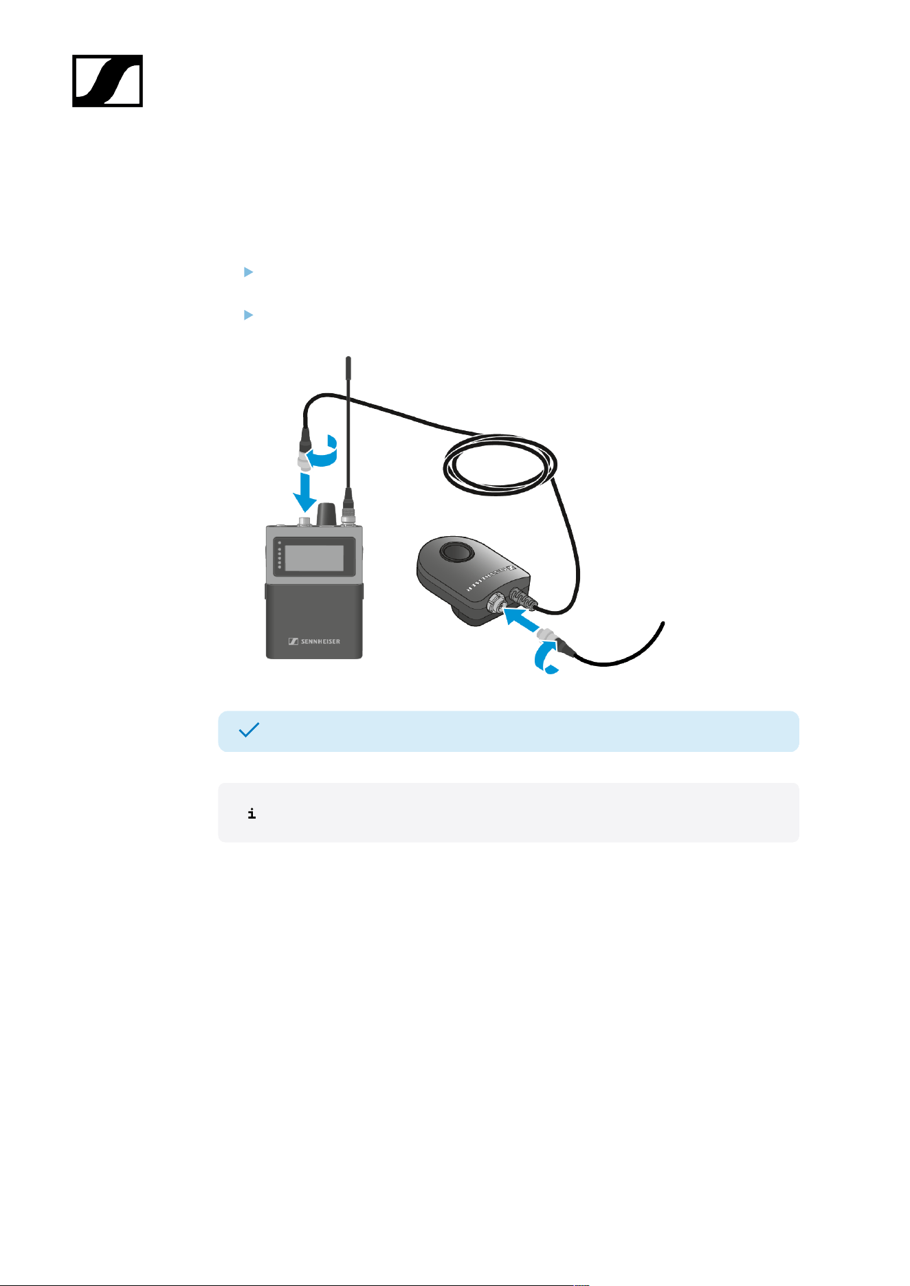
| 4 - Instruction manual
Connecting the COM Button
The COM Button can be programmed with different functions, like mute or push to talk.
To connect the COM button to the SEK:
Connect the 3-pin audio connector of the COM Button to the microphone /
instrument input socket of the SEK.
Connect the 3-pin audio connector of the Sennheiser microphone or the Sennheiser
line/instrument cable to the 3-pin audio socket of the COM Button.
The COM Button has been connected.
The KA 9000 COM is not compatible with the Spectera system.
177
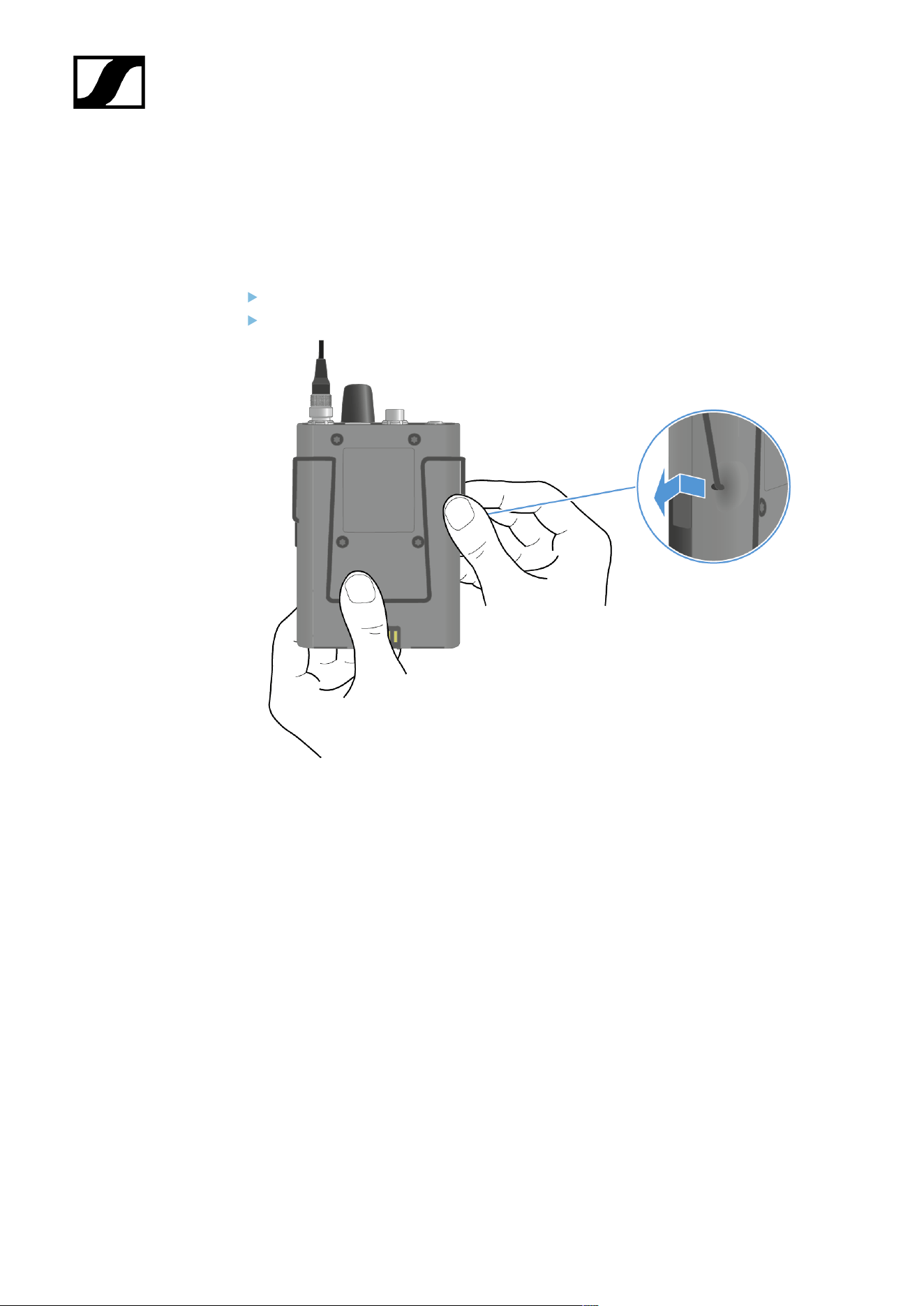
| 4 - Instruction manual
Changing the belt clip
You can change the belt clip on the SEK or flip it over depending on how you want to wear
it.
To remove the belt clip:
Hold down the belt clip with the thump to the housing.
Use the other hand to carefully pull back and then out one side of the belt clip.
178
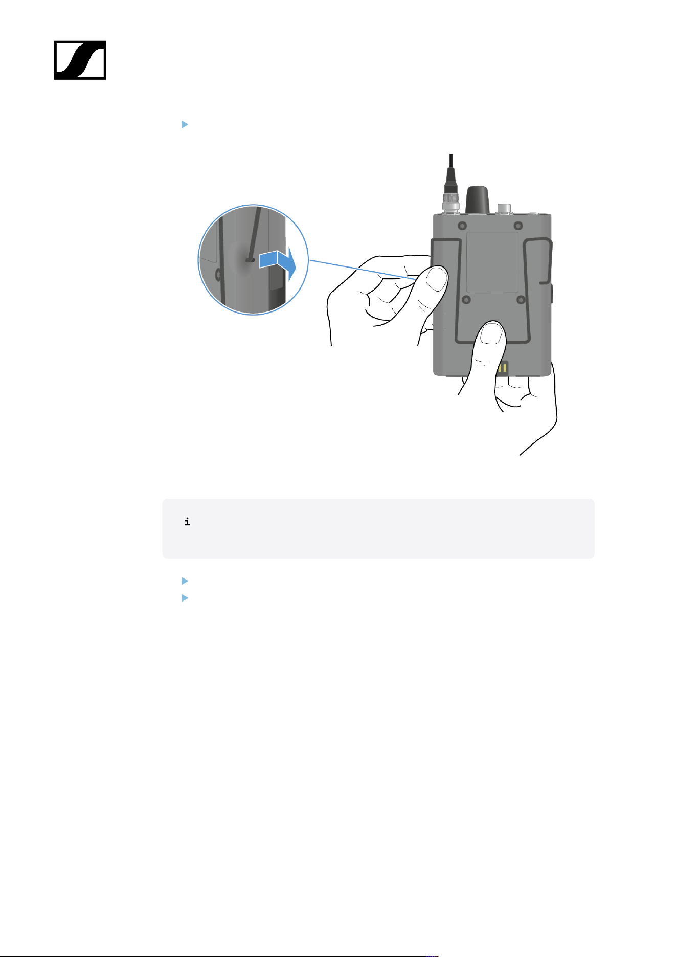
| 4 - Instruction manual
While still holding the belt clip down, carefully pull back and then out the other side of
the belt clip.
To insert the belt clip:
Always insert one side before the other, not at the same time, as otherwise the
belt clip could bend.
Hold down the belt clip with the thump to the housing.
Insert one side of the belt clip first.
179
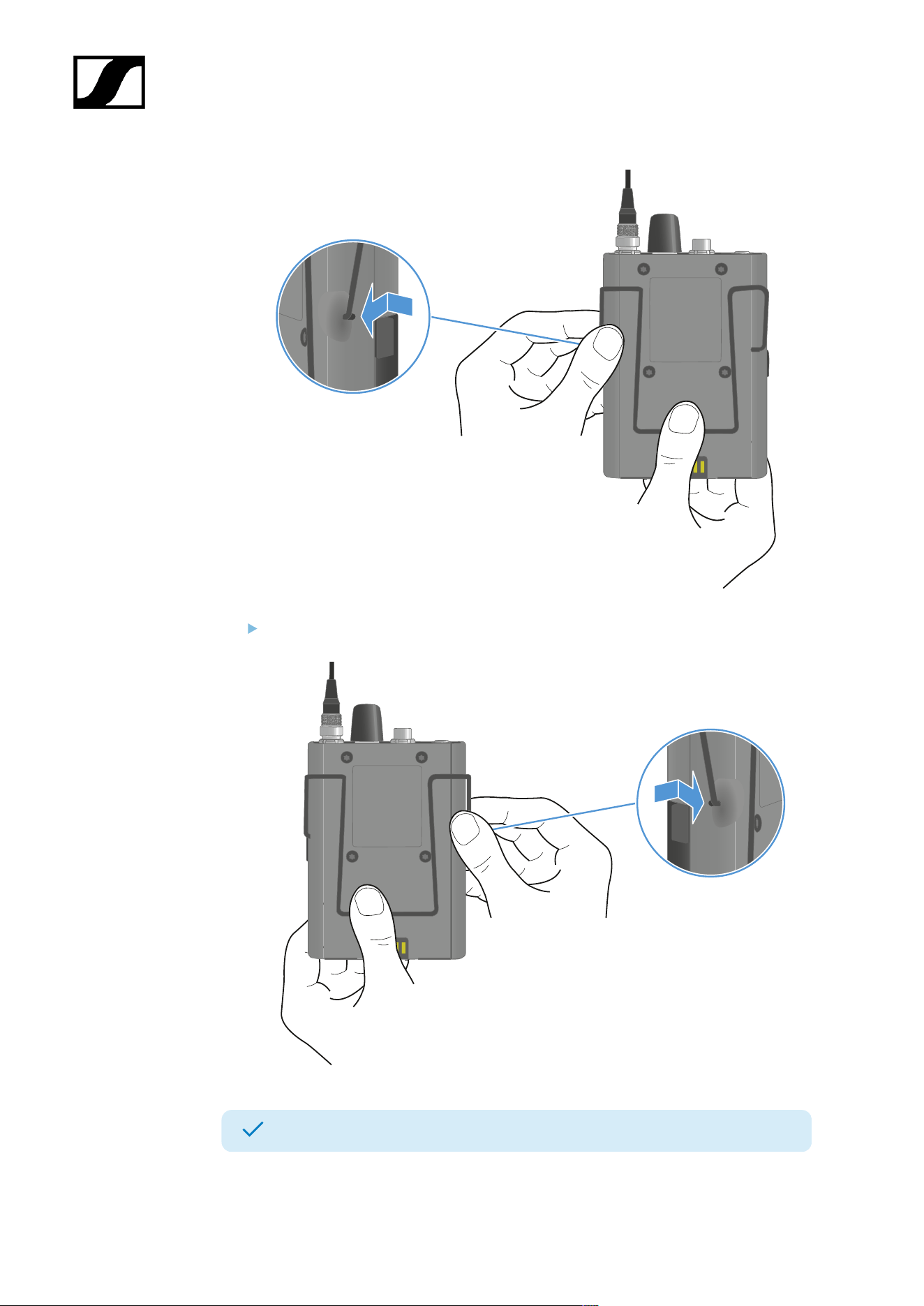
| 4 - Instruction manual
Then insert the second side of the belt clip.
The belt clip has been removed and inserted.
180
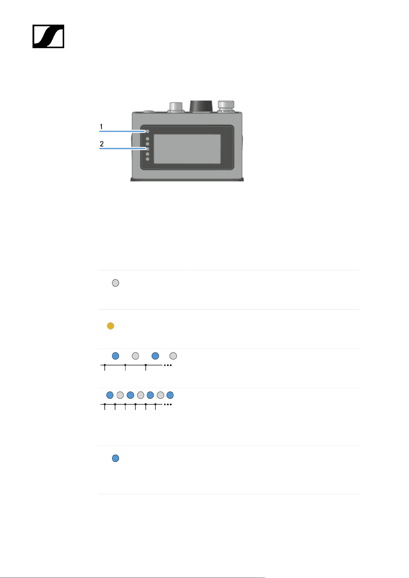
| 4 - Instruction manual
Meaning of the LEDs
The Status LED and LEDs can indicate the following information.
1 Status LED
2 LEDs
Status LED
The Status LED provides information about the status between the SEK and Base Station, as
well as status information for the SEK.
The LED is off:
• SEK is switched off
The LED is orange:
• SEK is starting
The LED is flashing blue:
• Searching for a new Base Station to pair
The LED is flashing blue quickly:
• Pairing to new Base Station is in progress
• SEK turns off after five minutes, when no Base
Station was found
The LED is blue:
• Connected to new Base Station, waiting for
confirmation
181
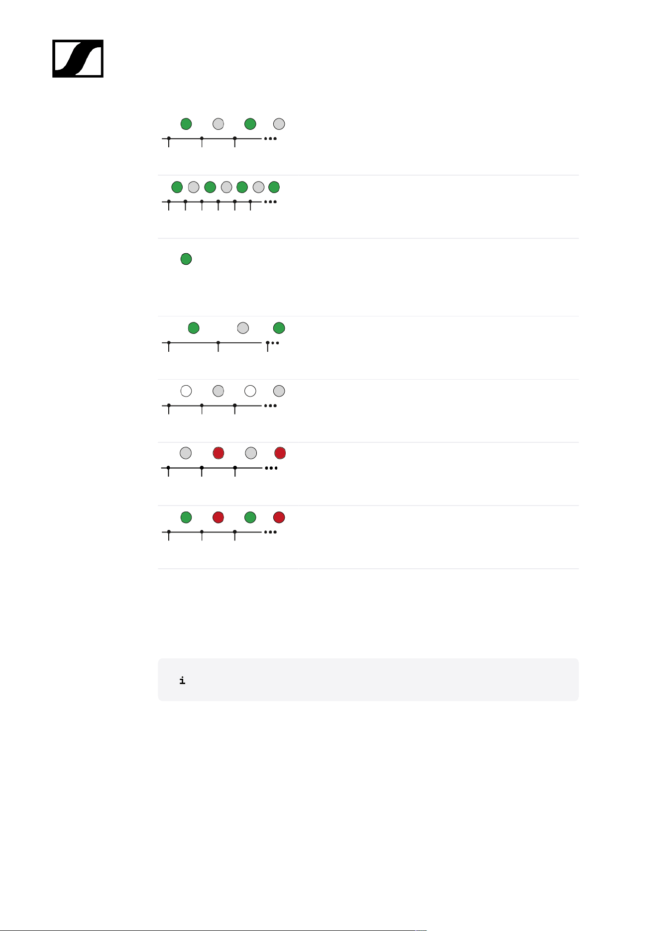
| 4 - Instruction manual
The LED is flashing green:
• SEK is searching for previously paired Base Station
The LED is flashing green quickly:
• SEK is connecting to previous paired Base Station
The LED is green:
• SEK is on
• SEK is connected to the Base Station
The LED is pulsing green:
• SEK is in sleep mode
The LED is flashing white:
• Identify of SEK is in progress
The LED is flashing red:
• Battery state is below 10 %
The LED is flashing green and red:
• Firmware update is in progress
LEDs
The LEDs provide information about the mic line input level, if a microphone or instrument is
connected to the SEK.
You have to set up an audio link in Spectera WebUI.
182
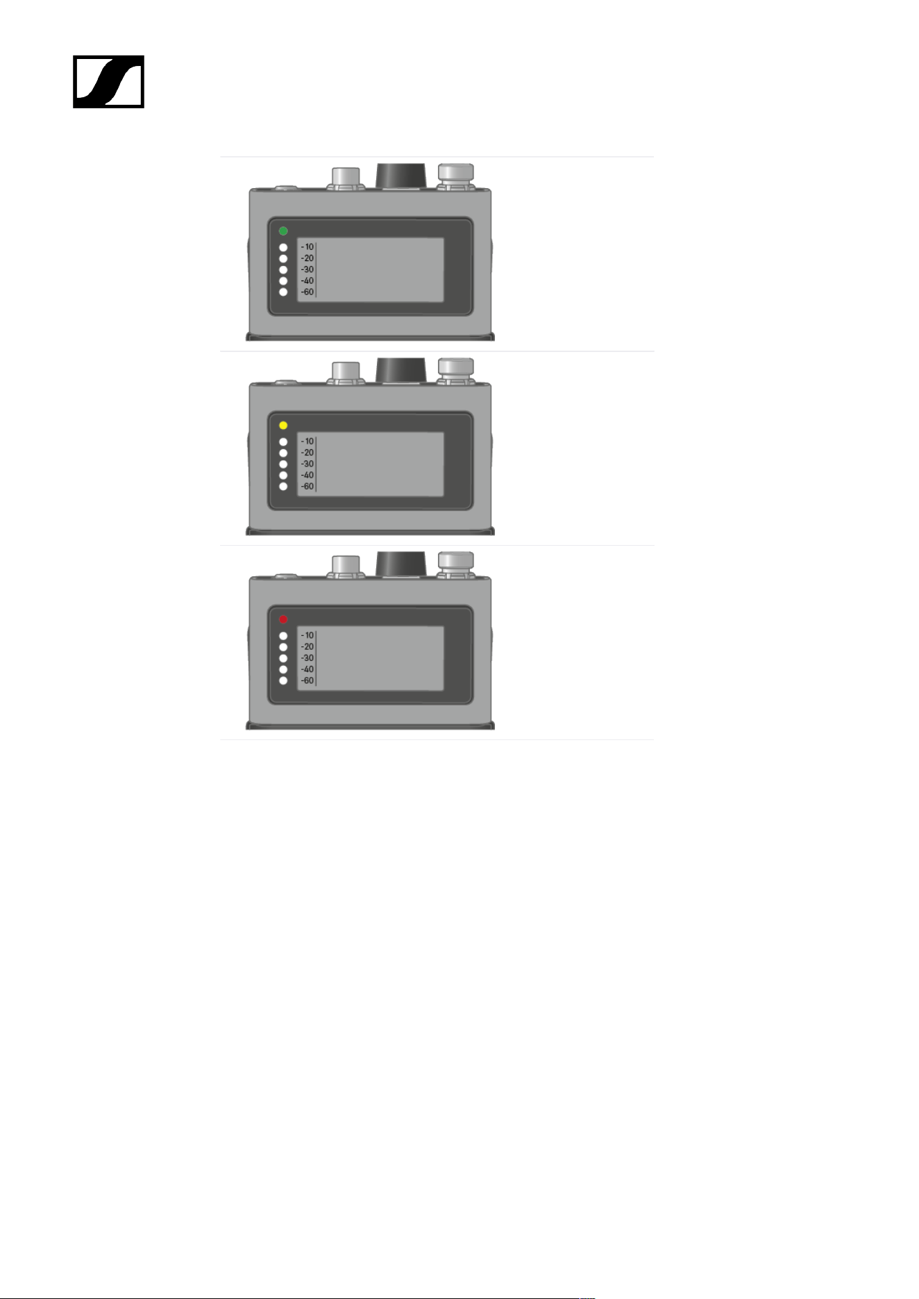
| 4 - Instruction manual
above -5 dBFS RMS
above -1 dBFS
PEAK
183
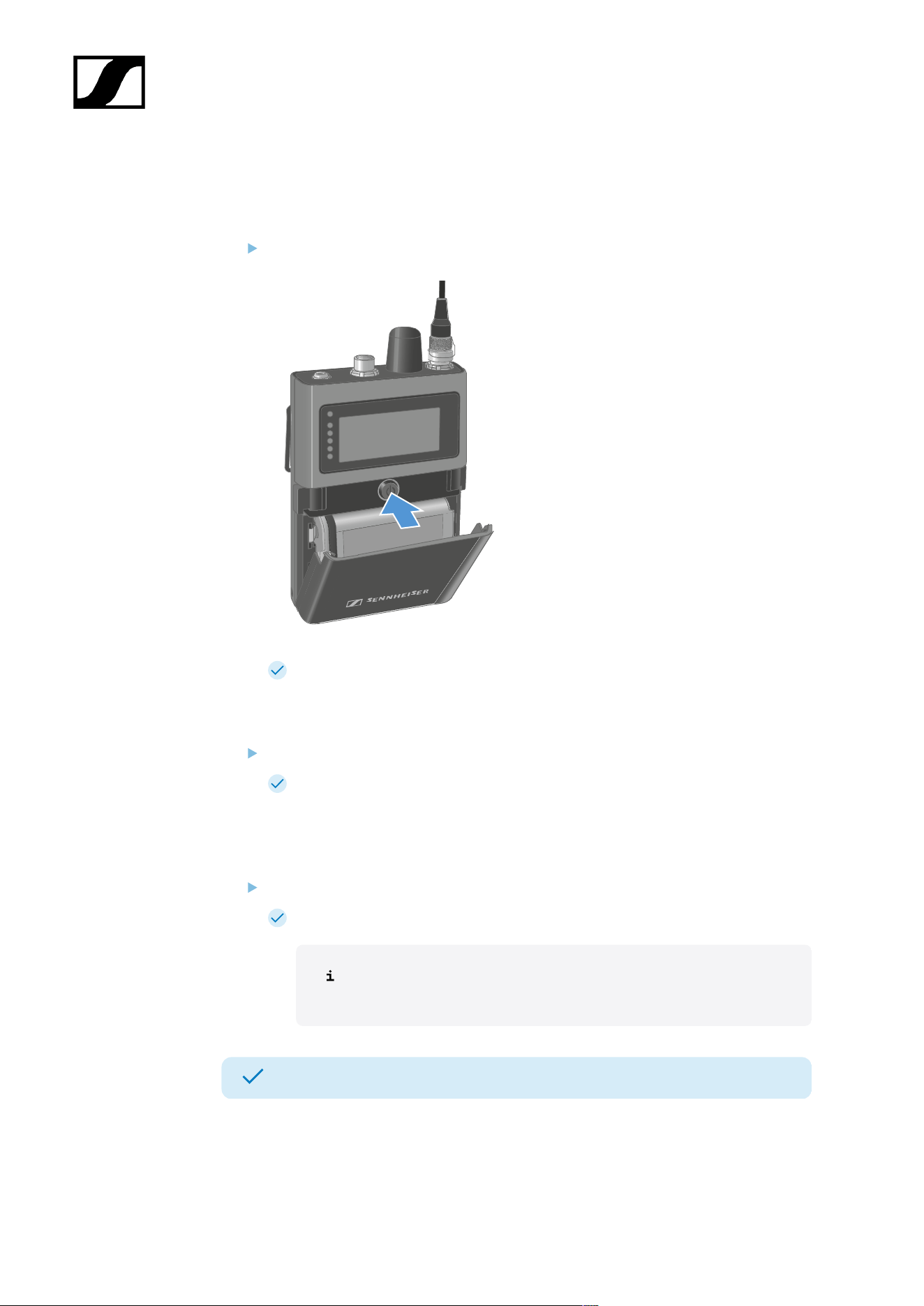
| 4 - Instruction manual
Switching the SEK on and off
To switch the SEK on:
Short-press the ON/OFF button.
The SEK is starting. The status LED is orange.
To put the SEK in pairing mode:
When the SEK is off, long press the ON/OFF button.
The SEK is searching for a new Base Station to pair. The status LED is flashing
blue.
To switch the SEK off:
Press the ON/OFF button.
The status LED goes off.
The display will stay on when the device is switched off or the battery
has been removed.
The SEK has been switched on/off.
When the SEK is unpaired via the software Spectera WebUI, the SEK will automatically
switch into pairing mode. The status LED is flashing blue.
184

| 4 - Instruction manual
Sleep mode
The SEK switches to sleep mode after 5 minutes if it cannot establish a connection to the
Base Station. The LED then pulses green.
Once per 20 seconds, the SEK wakes up automatically and checks whether a connection to
the Base Station can be established.
Operating the jog dial wakes the SEK up immediately and it attempts to establish a
connection.
In doing so, the SEK searches for a connection for 10 seconds.
If a connection is established, the SEK remains active; otherwise, it switches back to sleep
mode.
185
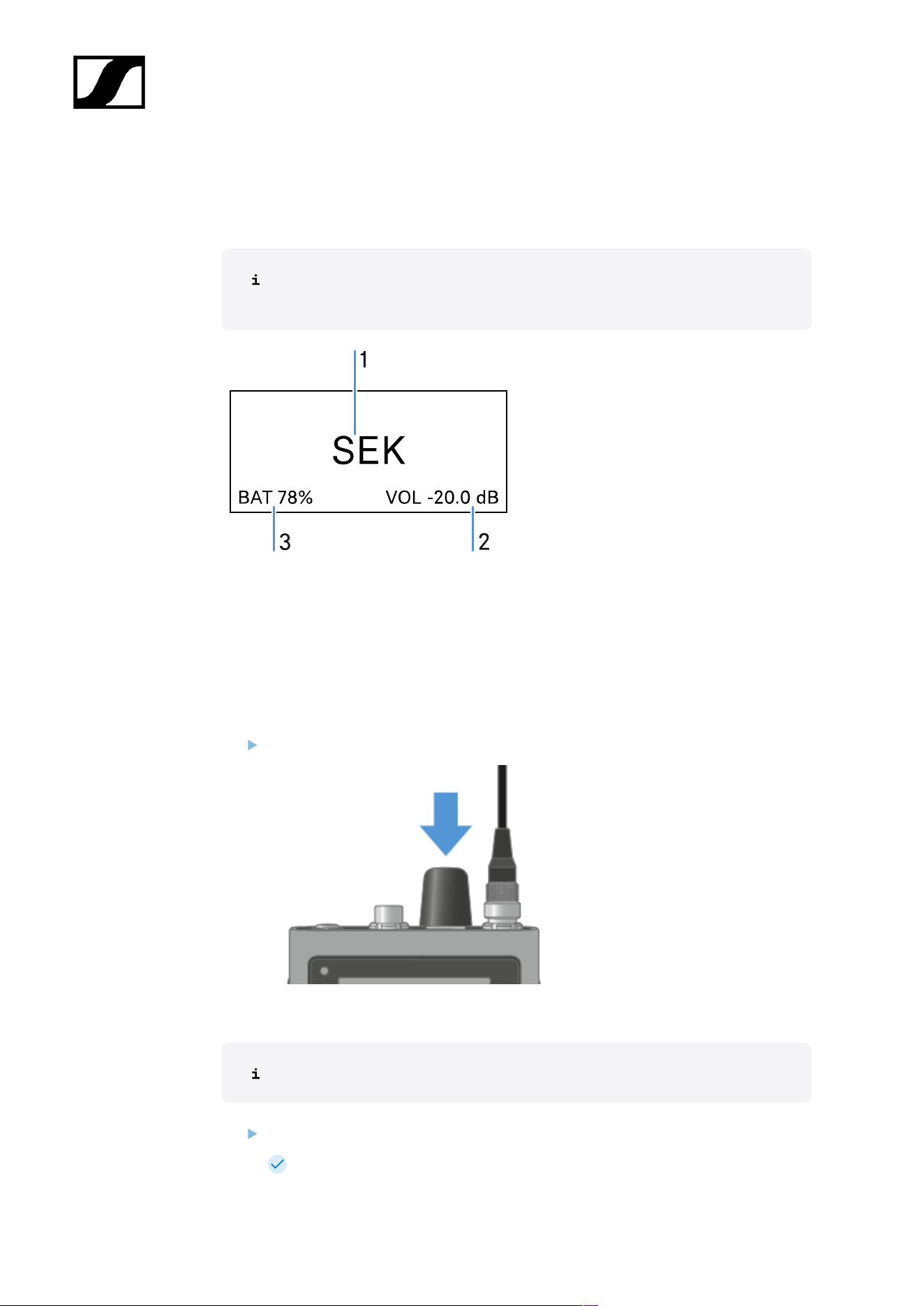
| 4 - Instruction manual
Information on the display
You can view the following information on the SEKs display.
The display will stay on when the device is switched off or the battery has been
removed.
1 Name of mobile device
2 In-Ear volume level (only applicable when an audio link mode for IEM is set)
3 Battery status
The order of the displayed information changes depending on the setting.
Press the rotary encoder to navigate through the menu.
To turn on the backlight:
No microphone or headphone is connected.
Press the rotary encoder.
The backlight is on for five seconds.
186
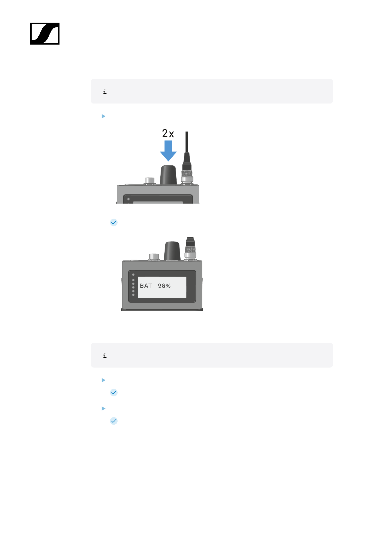
| 4 - Instruction manual
To check the battery status:
No audio link is set.
Press the rotary encoder for two times.
The battery status displays for five seconds.
To display the headphone volume:
Only available if in-ear audio link mode is activated.
Press the rotary encoder.
The backlight is on for five seconds.
Press the rotary encoder again within 5 seconds after the first press.
The headphone volume displays for five seconds.
187
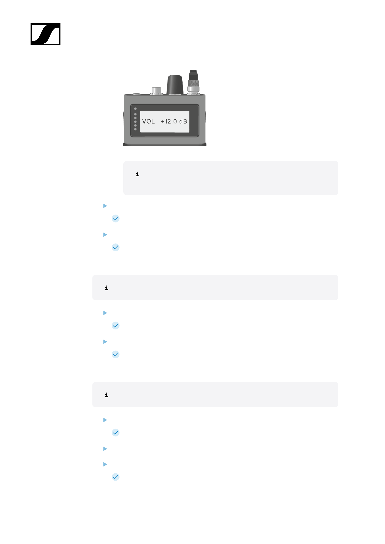
| 4 - Instruction manual
The volume can be altered between -100 dB to +27.5 dB in steps of
0.5 dB.
Turn the rotary encoder slowly to change the volume.
The volume changes by 0.5 dB per click.
Turn the rotary encoder quick to change the volume.
The volume changes dynamically in larger increments.
To display the mic/line level:
Only available if mic audio link is activated.
Press the rotary encoder.
The backlight is on for five seconds.
Press the rotary encoder again within 5 seconds after the first press.
The mic/line level is displayed. The five LEDs show the input level.
To display the E-label:
The SEK is paired to the Base Station and the activated license uses E-labels.
Press the rotary encoder.
The backlight is on for five seconds.
Press the rotary encoder till the end of the menu.
Press the rotary encoder long for E-label screen.
The first page of the E-label displays.
188

| 4 - Instruction manual
Press the rotary encoder again to display subsequent E-labels.
Press the rotary encoder long to return to the information screen.
Press the rotary encoder for two seconds to leave the E-label menu.
189

| 4 - Instruction manual
Pairing the SEK to the Base Station
Mobile devices can only be paired and operated with one Base Station at a time.
You can pair up to 128 mobile devices to a Base Station within one RF channel.
Please make sure that on the Base Station
• a RF channel is configured and
• this RF channel is activated (RF on).
To pair the SEK to a Base Station:
Put the Base Station into Pairing Mode using Spectera WebUI.
The LED flashes blue.
Pairing Mode is activated for five minutes. The audio signal is not
interrupted.
While the SEK is off, long-press the ON/OFF button until the Status LED is blue.
The status LED is flashing blue while searching for a new Base Station.
When the SEK found the Base Station, the status LED is flashing blue quickly and
then is blue.
The SEK appears in the software.
Confirm the pairing in the software, see Spectera WebUI: Pairing/unpairing mobile
devices.
The status LED of the SEK is flashing green quickly while connecting. When
connecting is completed, the status LED is green.
To unpair the SEK from a Base Station:
The SEK can only be unpaired in Spectera WebUI.
• Spectera WebUI: Pairing/unpairing mobile devices
The SEK will automatically switch to pairing mode. The status LED is flashing
blue.
The SEK has been paired to a Base Station.
190
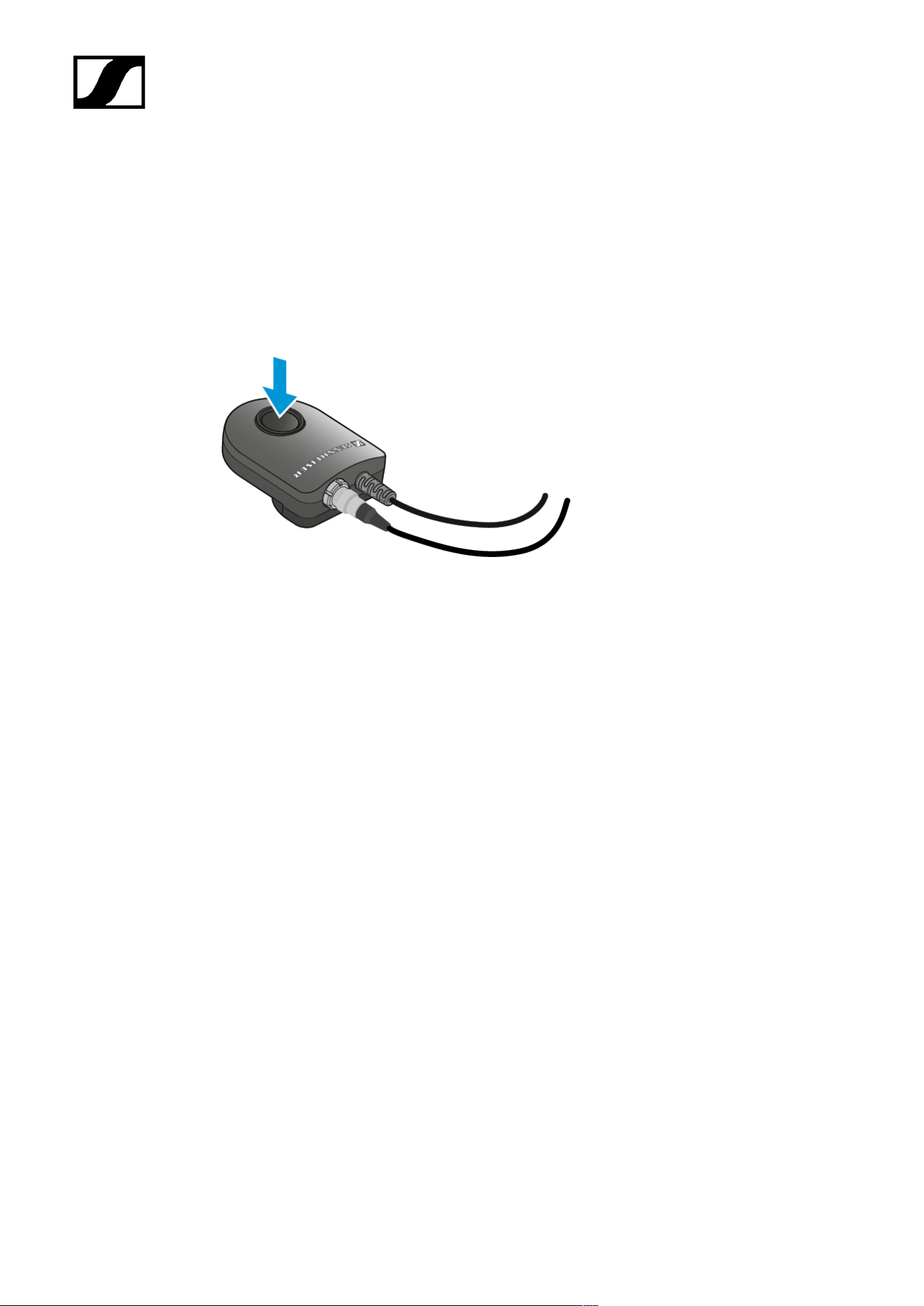
| 4 - Instruction manual
Operating the SEK with the COM Button
The COM Button can be programmed with different functions, like mute or push to talk.
You can set the function of the COM button in the WebUI (see Setting the command mode)
for each selected audio output channel on the Base Station.
• Momentary
• Latching
191
| 4 - Instruction manual
Updating the SEK
You can update the firmware of the SEK via Spectera WebUI.
All Spectera devices must use the same firmware version. The Base Station determines the
firmware version.
NOTICE
Data loss during firmware update
The audio transmission is interrupted during the firmware update of the
Base Station, the antenna or the mobile device.
After the firmware update, the device is restarted automatically.
Do not update the firmware during an active live audio
transmission.
The remaining battery state must be higher than 10 % to start the update.
To update the firmware:
If you want to update the SEK via Spectera WebUI: Updating the firmware (mobile
devices).
The Status LED is flashing green and red during the update.
The firmware has been updated.
192
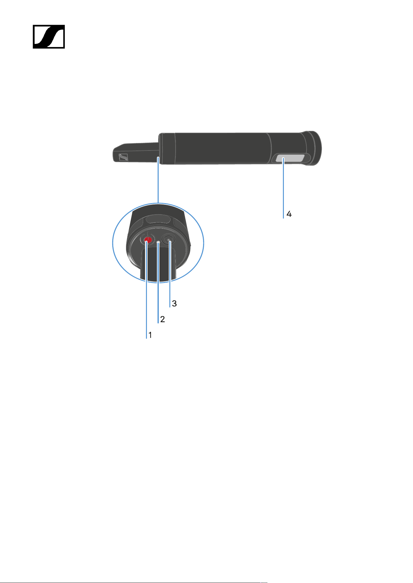
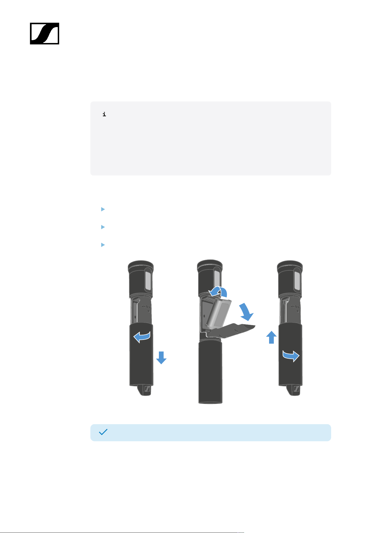
| 4 - Instruction manual
Inserting and removing the rechargeable battery
The handheld transmitter is powered exclusively by the BA 70 battery (separate accessory).
The BA 70 can be charged in the L 70 USB, the L 6000 with LM 6070 or with
the SEK in the CHG 70N-C.
• L 70 USB: Charging the rechargeable battery
• L 6000: Charging the rechargeable batteries in the L 6000 charger
• CHG 70N-C: Charging the rechargeable battery
To insert the battery into the handheld transmitter:
Unscrew the handheld transmitter housing as shown in the illustration and pull it
down as far as it will go.
Insert the BA 70 battery as indicated in the battery compartment. Make sure the
polarity is correct when inserting.
Screw the handheld transmitter housing back on.
The battery has been inserted.
194
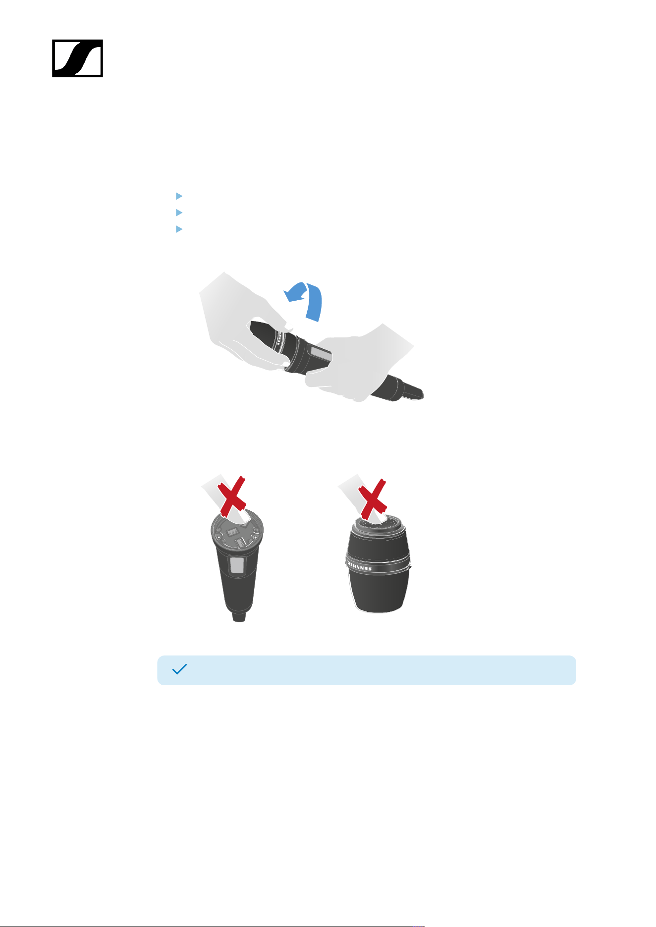
| 4 - Instruction manual
Replace microphone module
Different microphone modules are available for the handheld transmitter.
To replace the microphone module:
Unscrew the microphone module.
Screw on the desired microphone module.
Do not touch the contacts of the microphone or the microphone module, as you may
contaminate or bend them.
The microphone module has been replaced.
The following microphone modules are compatible with the SKM:
• MD 9235 (legacy product) | Dynamic microphone module with cardioid pickup pattern
• ME 9002 | Permanently polarized condenser microphone module with omnidirectional
pickup pattern
• ME 9004 | Permanently polarized condenser microphone module with cardioid pickup
pattern
• ME 9005 | Permanently polarized condenser microphone module with supercardioid
pickup pattern
195

| 4 - Instruction manual
• MM 435 | Dynamic microphone module with cardioid pickup pattern
• MM 445 | Dynamic microphone module with supercardioid pickup pattern
• MMD 42-1 | Dynamic microphone module with omnidirectional pickup pattern
• MMD 835-1 | Dynamic microphone module with cardioid pickup pattern
• MMD 845-1 | Dynamic microphone module with supercardioid pickup pattern
• MME 865-1 | Permanently polarized condenser microphone module with
supercardioid pickup pattern
• MMD 935-1 | Dynamic microphone module with cardioid pickup pattern
• MMD 945-1 | Dynamic microphone module with supercardioid pickup pattern
• MMK 965-1 | Condenser microphone module with switchable cardioid and
supercardioid pickup patterns
• Neumann KK 204 | Condenser microphone module with cardioid pickup pattern
• Neumann KK 205 | Condenser microphone module with supercardioid pickup pattern
196
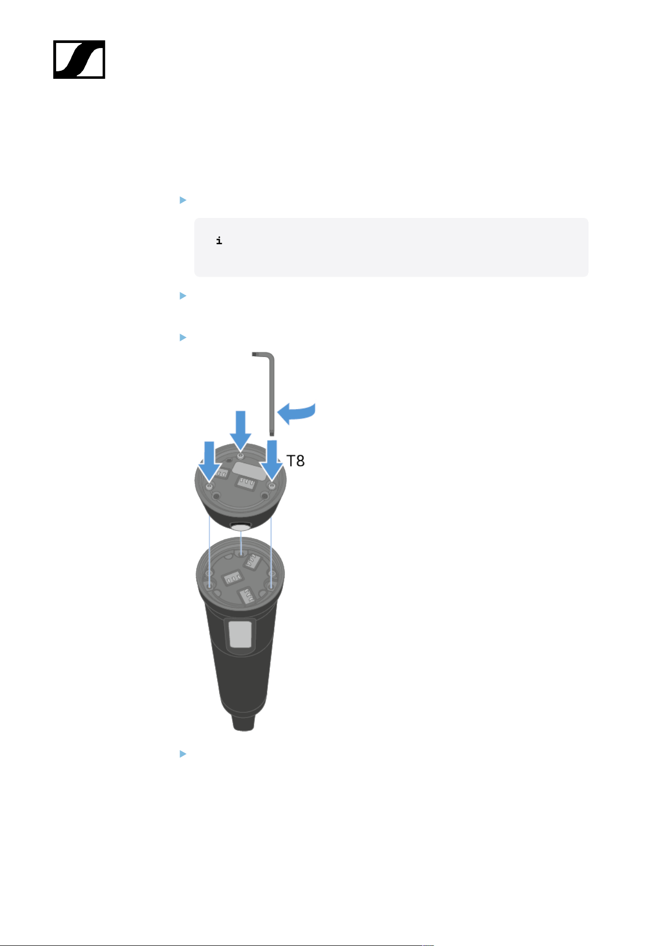
| 4 - Instruction manual
Attaching the SKM COM
The SKM COM with the push button adds additional functions to the SKM.
To attach the SKM COM:
Switch off the SKM.
The SKM must be switched off before the SKM COM is attached or
removed.
Place the SKM COM on the SKM so that the push button is positioned above the
display.
Tighten the 3 screws evenly by hand using the supplied angle screwdriver.
Screw on a compatible microphone module.
197
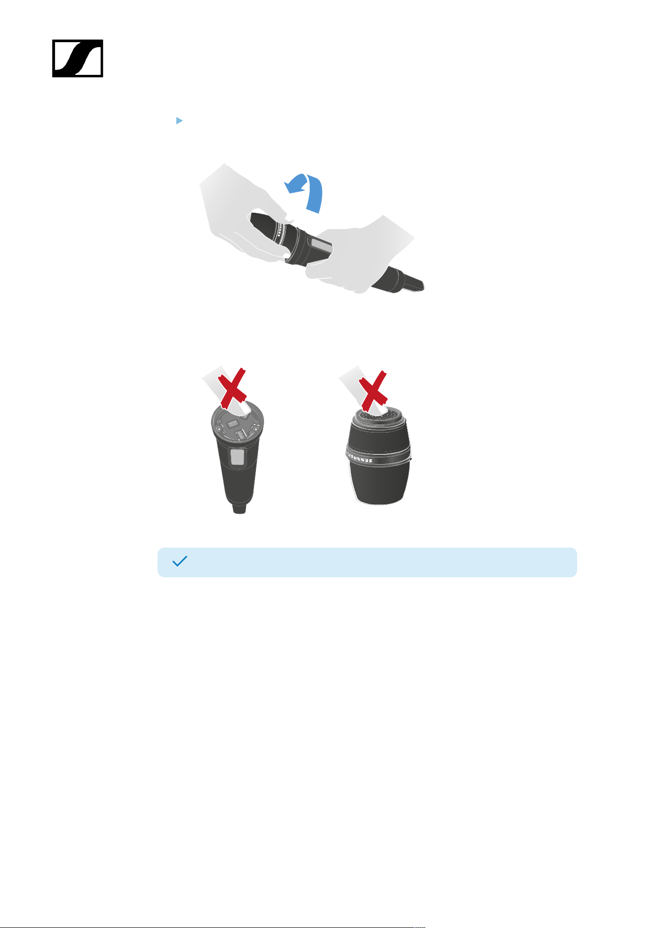
| 4 - Instruction manual
Do not touch the contacts of the microphone or the microphone module. You might
contaminate or bend them.
The SKM COM is attached to the SKM.
198
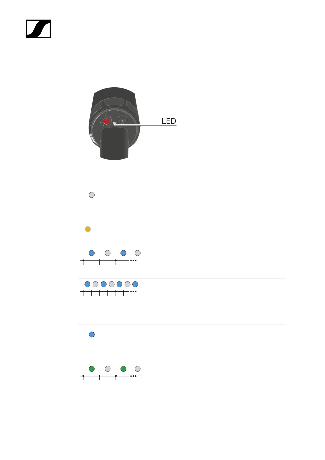
| 4 - Instruction manual
Meaning of the LED
The LED on the bottom of the SKM can display the following information.
The LED indicates the status between the SKM and the Base Station.
The LED is off:
• SKM is switched off
The LED is orange:
• SKM is starting
The LED is flashing blue:
• Searching for a new Base Station to pair
The LED is flashing blue quickly:
• Pairing to new Base Station is in progress
• SKM turns off after five minutes, when no Base
Station was found
The LED is blue:
• Connected to new Base Station, waiting for
confirmation
The LED is flashing green:
• SKM is searching for previously paired Base Station
199
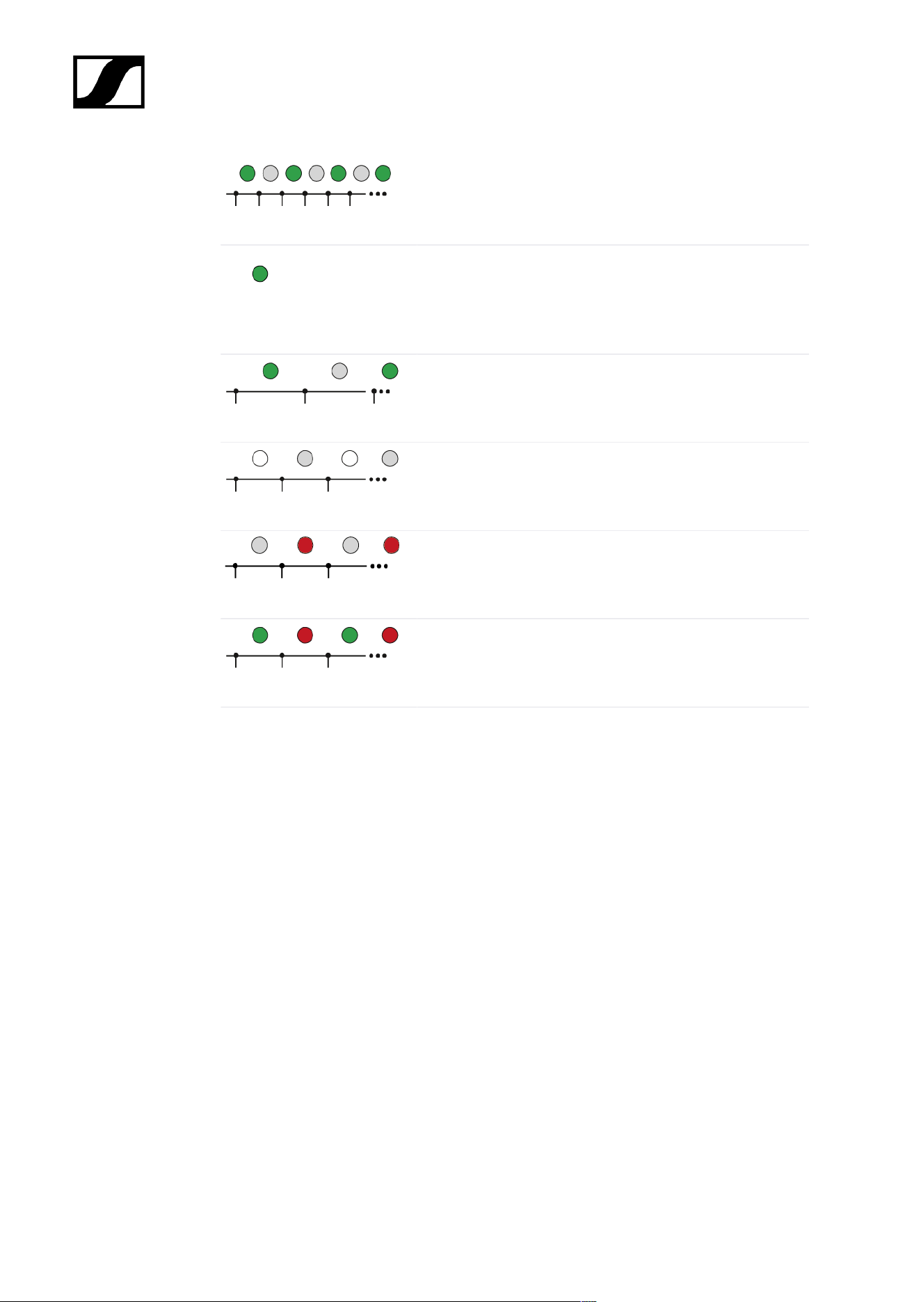
| 4 - Instruction manual
The LED is flashing green quickly:
• SKM is connecting to previous paired Base Station
The LED is green:
• SKM is on
• SKM is connected to the Base Station
The LED is pulsing green:
• SKM is in sleep mode
The LED is flashing white:
• Identify of SKM is in progress
The LED is flashing red:
• Battery state is below 10 %
The LED is flashing green and red:
• Firmware update is in progress
200
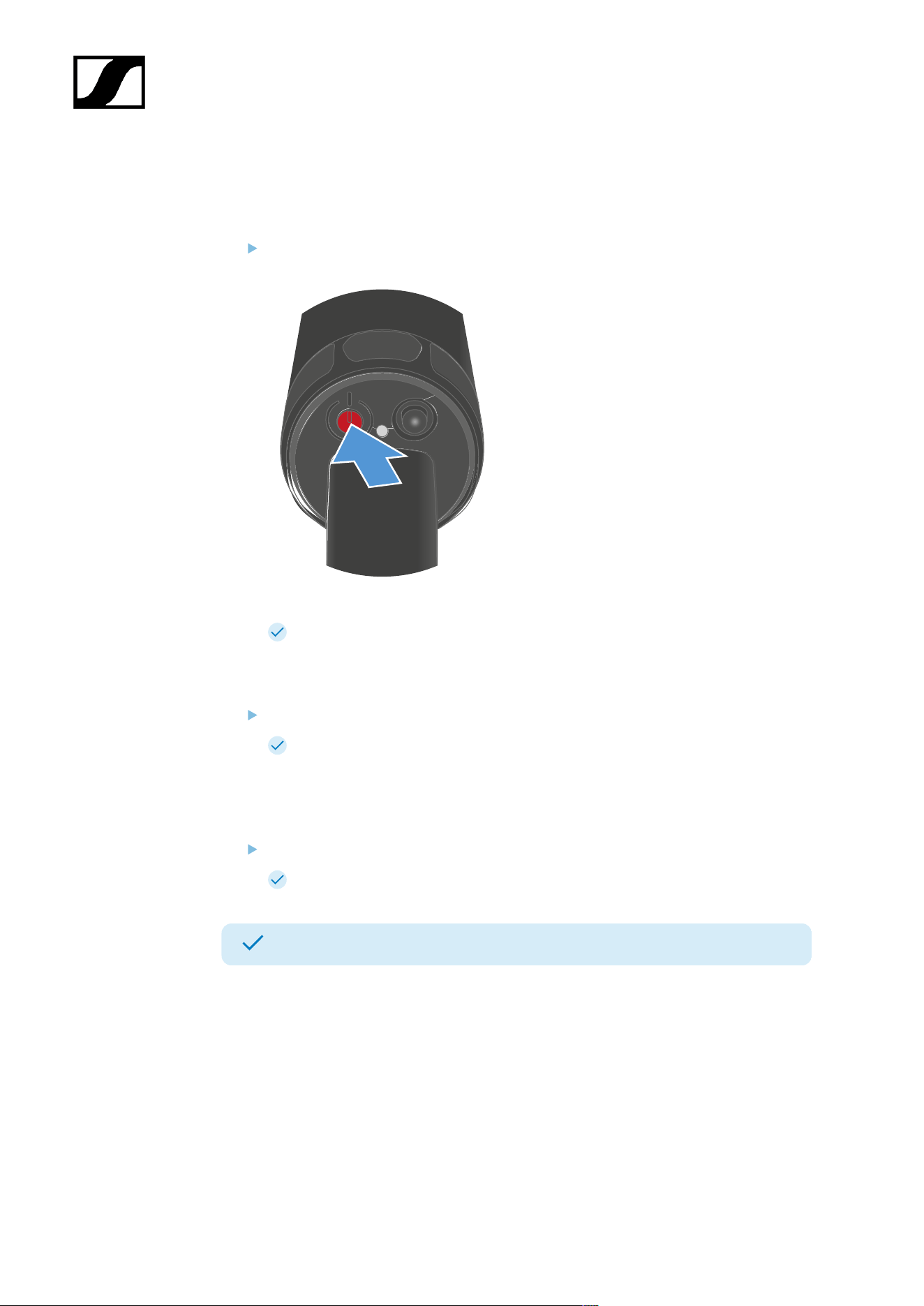
| 4 - Instruction manual
Switching the SKM on and off
To switch the SKM on:
Press the ON/OFF button for about three seconds.
The SKM is starting. The status LED is orange.
To put the SKM in pairing mode:
When the SKM is switched off, press the ON/OFF button for about seven seconds.
The SKM is searching for a new Base Station to pair. The status LED is flashing
blue.
To switch the SKM off:
Press the ON/OFF button.
The status LED goes off.
The SKM has been switched on/off.
When the SKM is unpaired via the software Spectera WebUI, the SKM will automatically
switch into pairing mode. The status LED is flashing blue.
Sleep mode
The SKM switches to sleep mode after 5 minutes if it cannot establish a connection to the
Base Station. The LED then pulses green.
Once per 20 seconds, the SKM wakes up automatically and checks whether a connection to
the Base Station can be established.
201

| 4 - Instruction manual
Operating the jog dial wakes the SKM up immediately and it attempts to establish a
connection.
In doing so, the SKM searches for a connection for 10 seconds.
If a connection is established, the SKM remains active; otherwise, it switches back to sleep
mode.
202
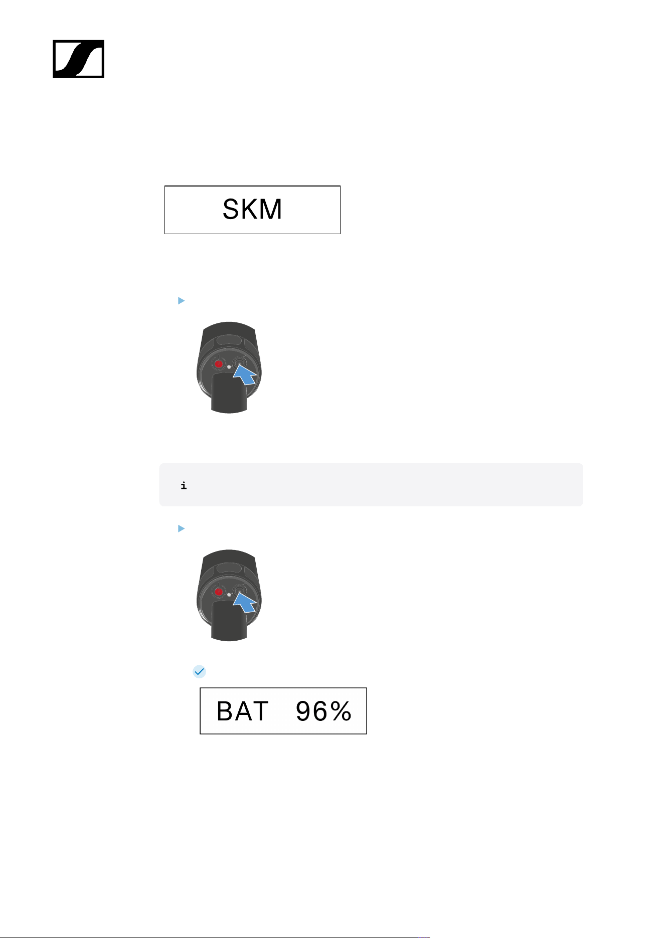
| 4 - Instruction manual
Information on the display
You can view the following information on the SKMs display.
The order of the displayed information changes depending on the setting.
Press the Control button to navigate through the menu.
To check the battery status:
No audio link is configured.
Press the Control button.
The battery status is displayed for five seconds.
203

| 4 - Instruction manual
To display the E-Label:
The SKM is paired with the Base Station and the enabled license uses E-Labels.
Press the Control button until you reach the end of the menu.
Press and hold the Control button to display the E-Label window.
The first page of the E-Label is displayed.
Press the Control button again to display subsequent E-Labels.
Press and hold the Control button to return to the information window.
Press and hold the Control button for two seconds to exit the E-Label menu.
204

| 4 - Instruction manual
Pairing the SKM to the Base Station
Mobile devices can only be paired and operated with one Base Station at a time.
You can pair up to 128 mobile devices to a Base Station within one RF channel.
Please make sure that on the Base Station
• a RF channel is configured and
• this RF channel is activated (RF on).
To pair the SKM to a Base Station:
Put the Base Station into Pairing Mode using Spectera WebUI.
The LED flashes blue.
Pairing Mode is activated for five minutes. The audio signal is not
interrupted.
While the SKM is off, long-press the ON/OFF button until the Status LED is blue.
The status LED is flashing blue while searching for a new Base Station.
When the SKM found the Base Station, the status LED is flashing blue quickly and
then is blue.
The SKM appears in the software.
Confirm the pairing in the software, see Spectera WebUI: Pairing/unpairing mobile
devices.
The status LED of the SKM is flashing green quickly while connecting. When
connecting is completed, the status LED is green.
To unpair the SKM from a Base Station:
The SKM can only be unpaired in Spectera WebUI.
• Spectera WebUI: Pairing/unpairing mobile devices
The SKM will automatically switch to pairing mode. The status LED is flashing
blue.
The SKM has been paired to a Base Station.
205
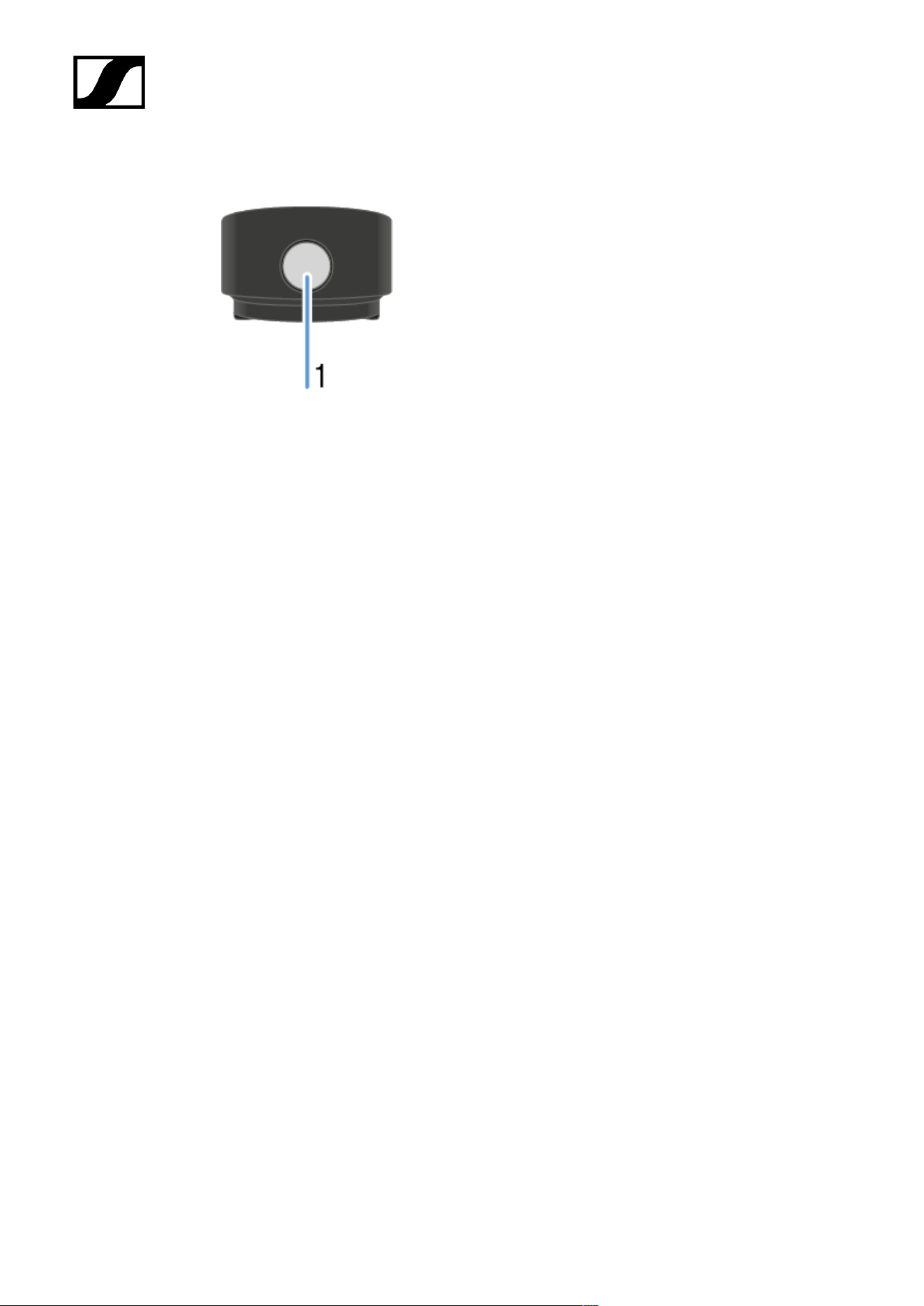
| 4 - Instruction manual
Updating the SKM
You can update the firmware of the SKM via Spectera WebUI.
All Spectera devices must use the same firmware version. The Base Station determines the
firmware version.
NOTICE
Data loss during firmware update
The audio transmission is interrupted during the firmware update of the
Base Station, the antenna or the mobile device.
After the firmware update, the device is restarted automatically.
Do not update the firmware during an active live audio
transmission.
The remaining battery state must be higher than 10 % to start the update.
To update the firmware:
If you want to update the SKM via Spectera WebUI: Updating the firmware (mobile
devices).
The Status LED is flashing green and red during the update.
The firmware has been updated.
207
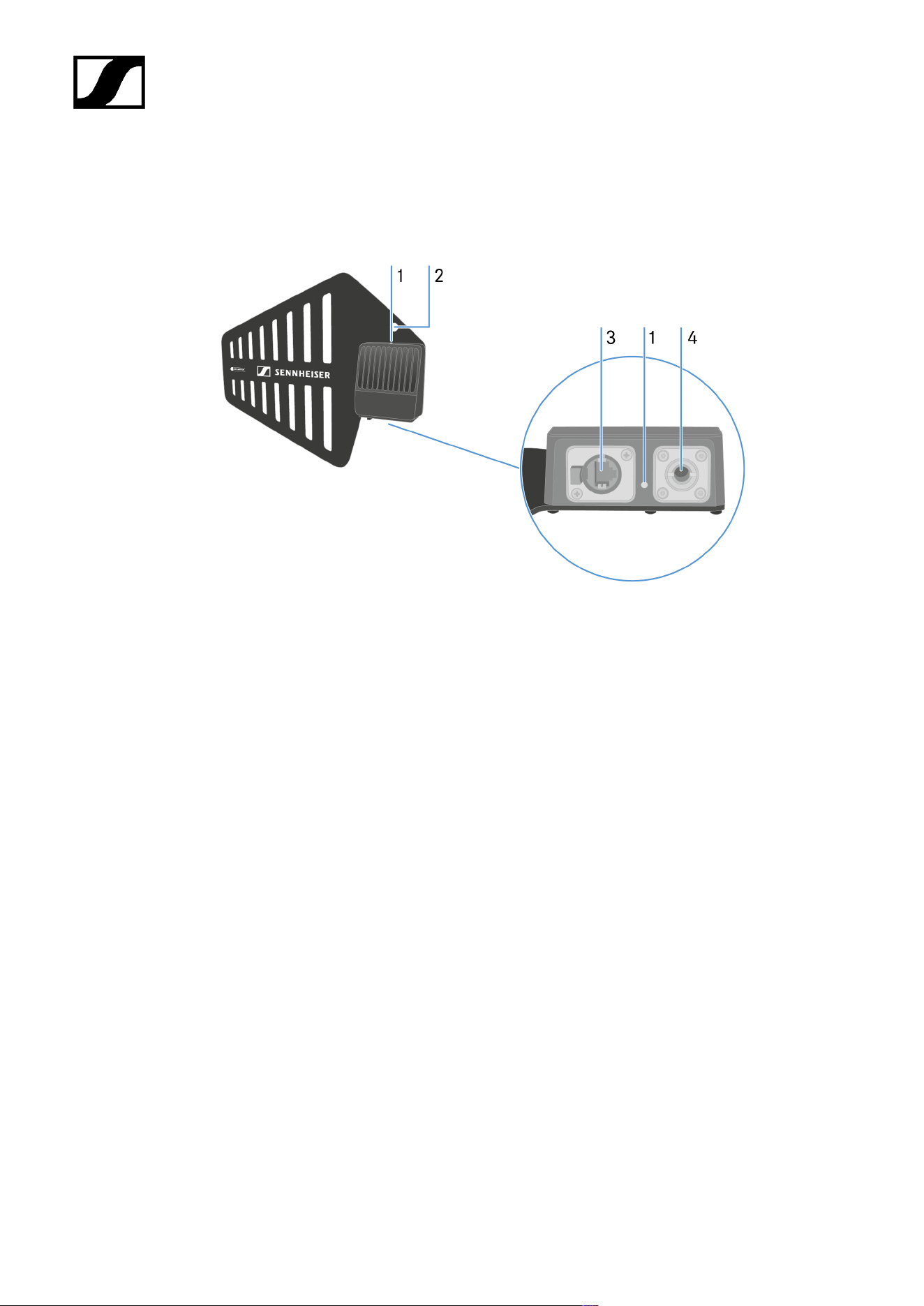
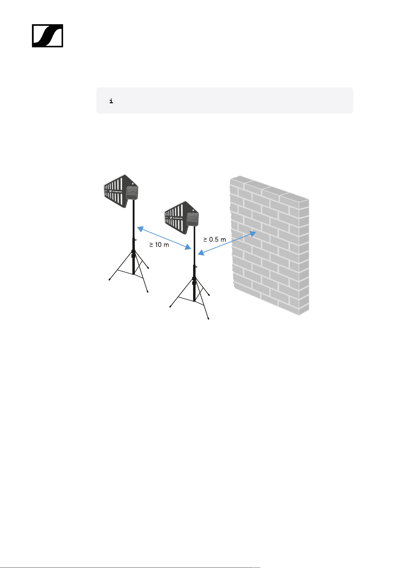
| 4 - Instruction manual
Information on antenna setup
Handle with care: The antenna contains electrical components.
Setup with other antennas
• Keep a distance more than 10 m (393.7") between the antenna and another antenna.
• Keep a distance more than 0.5 m (19.69") between the antenna and a wall.
Setup with a mobile device
• Keep a distance more than 5 m (169.85") between the antenna and the mobile device.
209
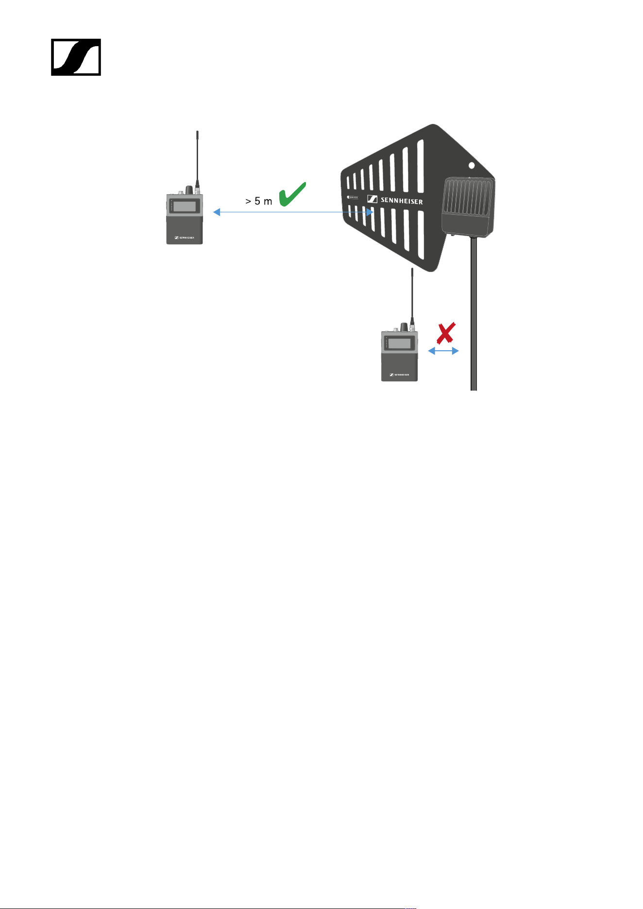
| 4 - Instruction manual
210
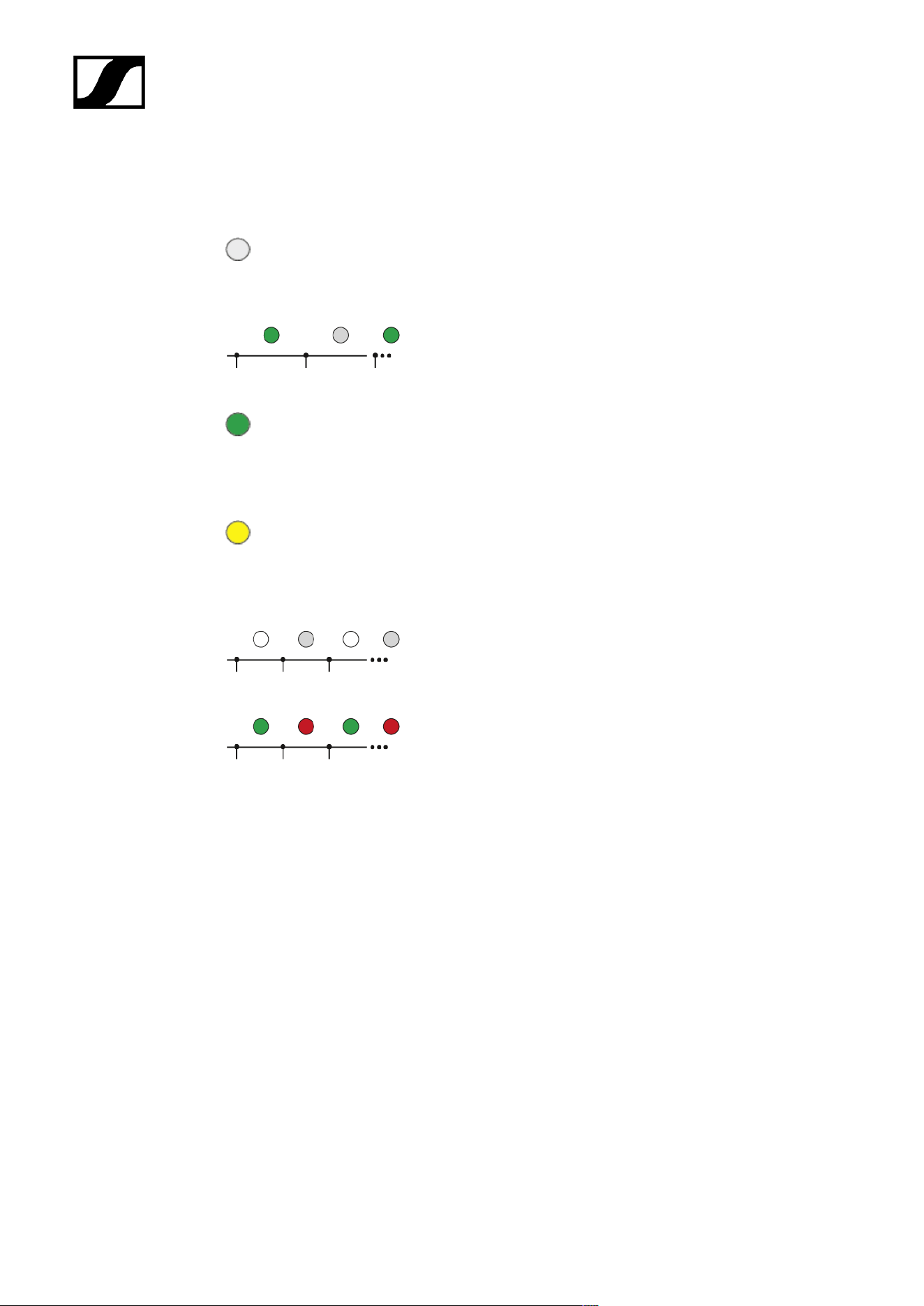
| 4 - Instruction manual
Meaning of the LED
The LED on top and below indicates the same information.
The LED is off:
• The antenna is not connected to the Base Station.
The LED is flashing green:
• The antenna is connecting to the Base Station.
The LED is green:
• The antenna is connected to the Base Station and one
or both RF channels are active.
The LED is yellow:
• The antenna is connected to the Base Station and one
or both RF channels are muted.
The LED is flashing white:
• The connected antenna is identified.
The LED is flashing green and red:
• Firmware update is in progress.
211

| 4 - Instruction manual
Placing on a stand
The thread is suitable for mounting on a standard microphone stand with 3/8" or 5/8"
thread.
Handle with care: The antenna contains electrical components.
CAUTION
Personal injury and damage to property if the antennae should
tip or fall over
If you do not secure the antennae against tipping or falling over, they may
cause personal injury and damage to property.
Secure antennae so that they cannot tip and fall over. Use safety
wires for this purpose. The safety wires, rope terminations and
coupling links must comply in their dimensioning and condition
with the regulations and standards of the country in which they
are used!
212
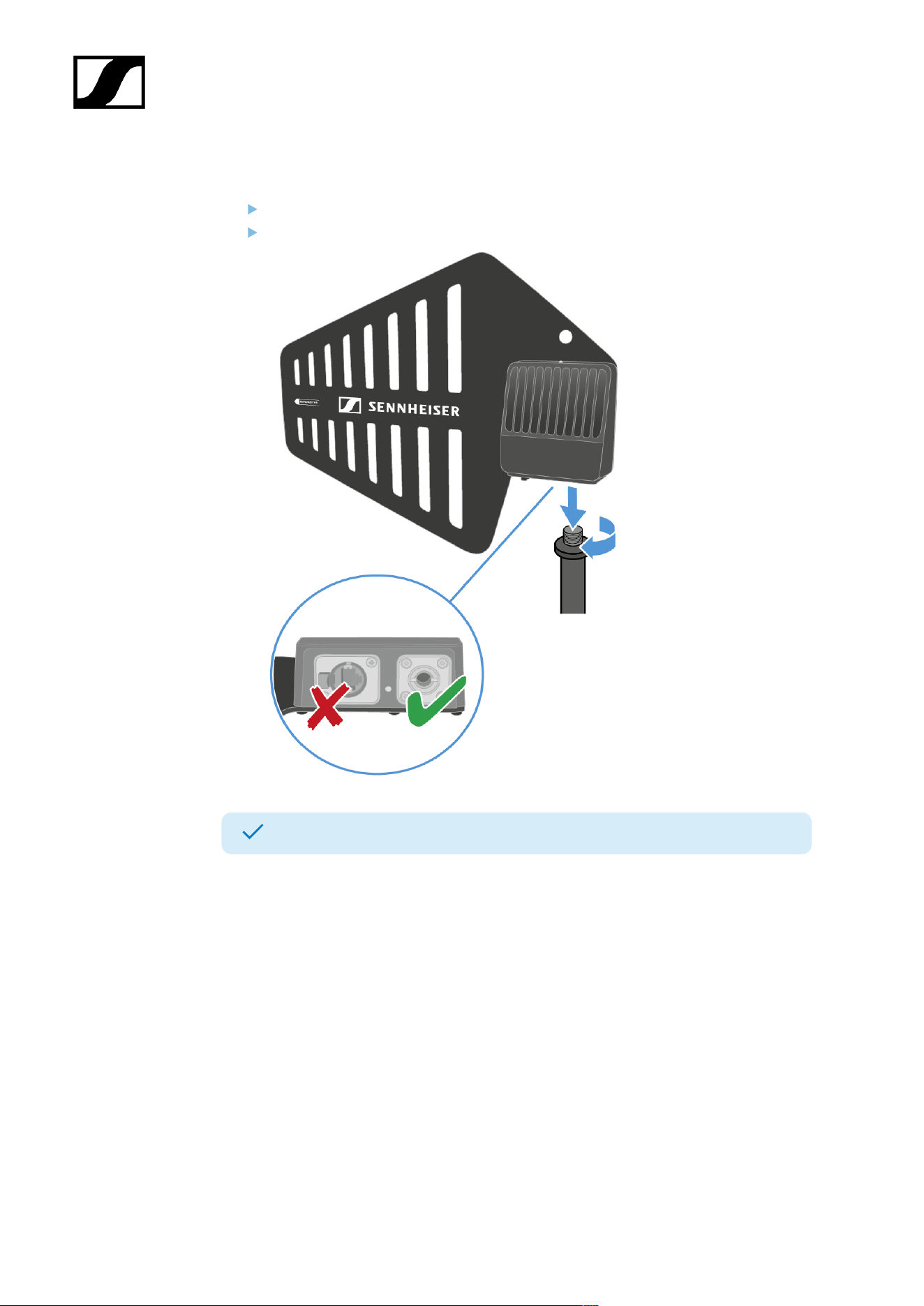
| 4 - Instruction manual
To place the DAD on a stand:
Screw the DAD to the stand.
Make sure to use the correct hole!
The DAD has been placed on a stand.
213
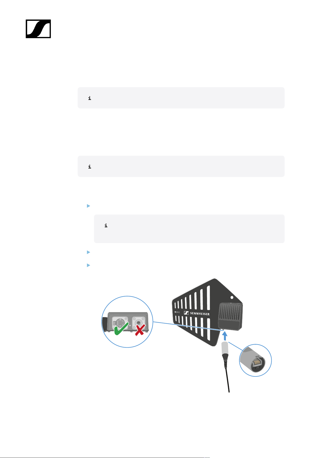
| 4 - Instruction manual
Connecting/disconnecting the antenna
The cable supplies power and exchanges data.
Handle with care: The antenna contains electrical components.
The cable must
• be a CAT5e or higher,
• have ruggedized plugs and
• not extend 100 m (3937").
We recommend using a antenna cable cat 5e (see Accessories for the DAD).
To connect the antenna to the Base Station:
Observe the information: Information on antenna setup.
The antenna must be connected directly to the Base Station, with no
switch in between.
Plug on side of the cable into the antenna.
Make sure to use the correct hole!
214
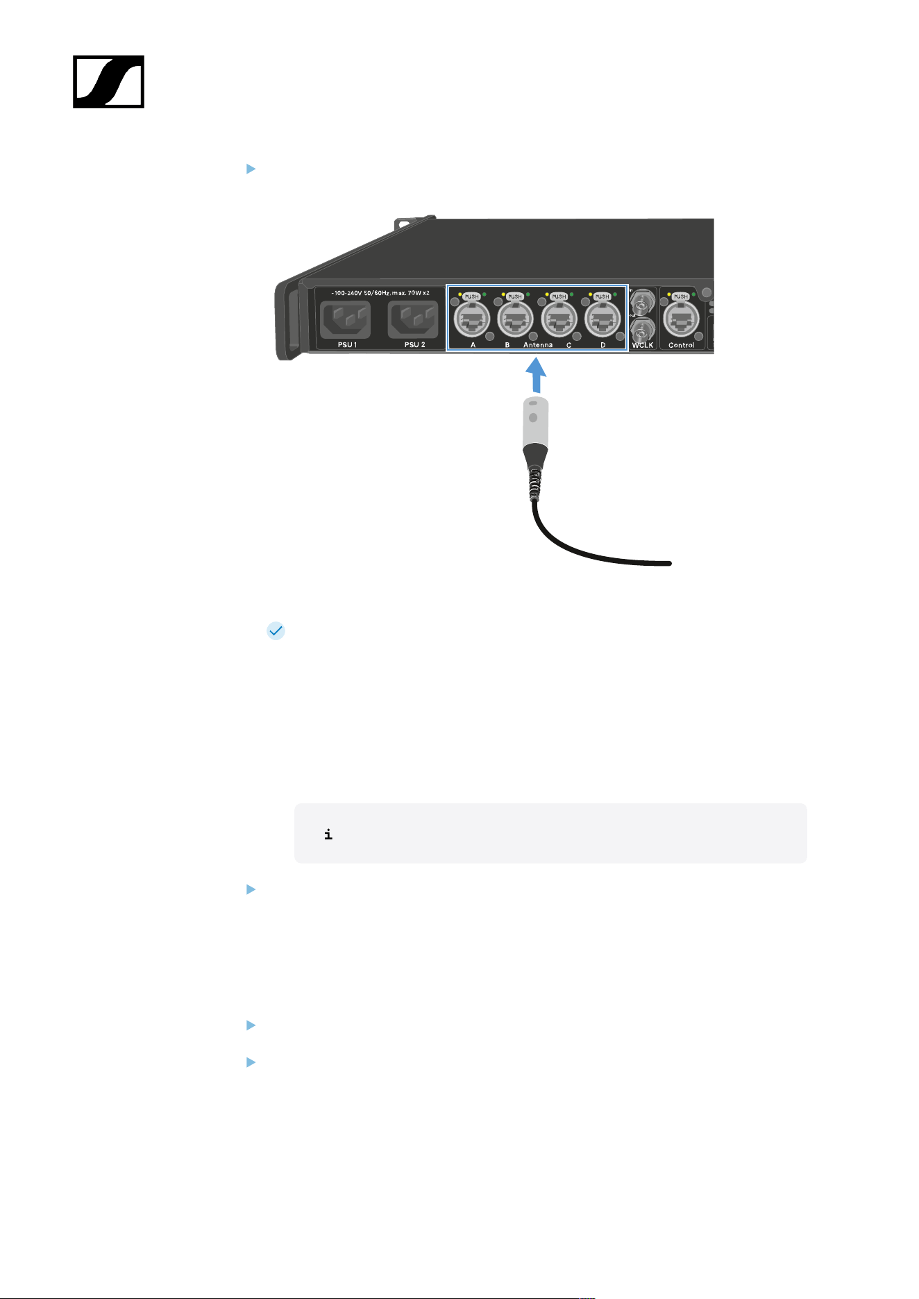
| 4 - Instruction manual
Plug the other side of the cable into one antenna port (A, B, C or D) at the rear site of
the Base Station.
The LED flashes green to connect to the Base Station.
The LED is green, when the antenna is connected to the Base Station and and one
or both RF channels are active.
Or the LED is yellow, when the antenna is connected to the Base Station and the
radio signal is muted.
Or the LED is flashing green and red, when the firmware is updating automatically.
If the Base Station is in standby, the DAD is off.
You can connect up to four antennas to one Base Station.
The Base Station has two independend RF channels. Both variants of the antenna
(UHF and 1G4) can be connected to the Base Station at the same time.
To disconnect the antenna from the Base Station:
Hold the push button down.
Unplug the cable from the Base Station.
215
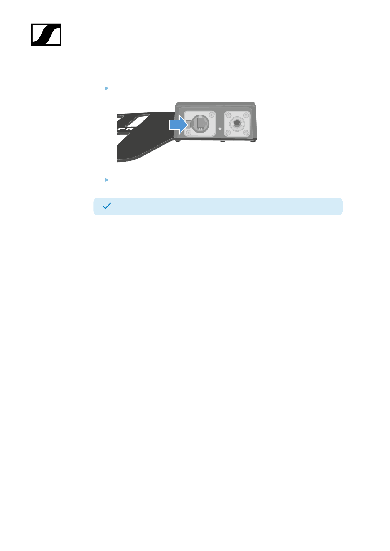
| 4 - Instruction manual
To disconnect the cable from the antenna:
Hold the snap-in nose down.
Unplug the cable from the antenna.
The antenna has been connected/disconnected.
216
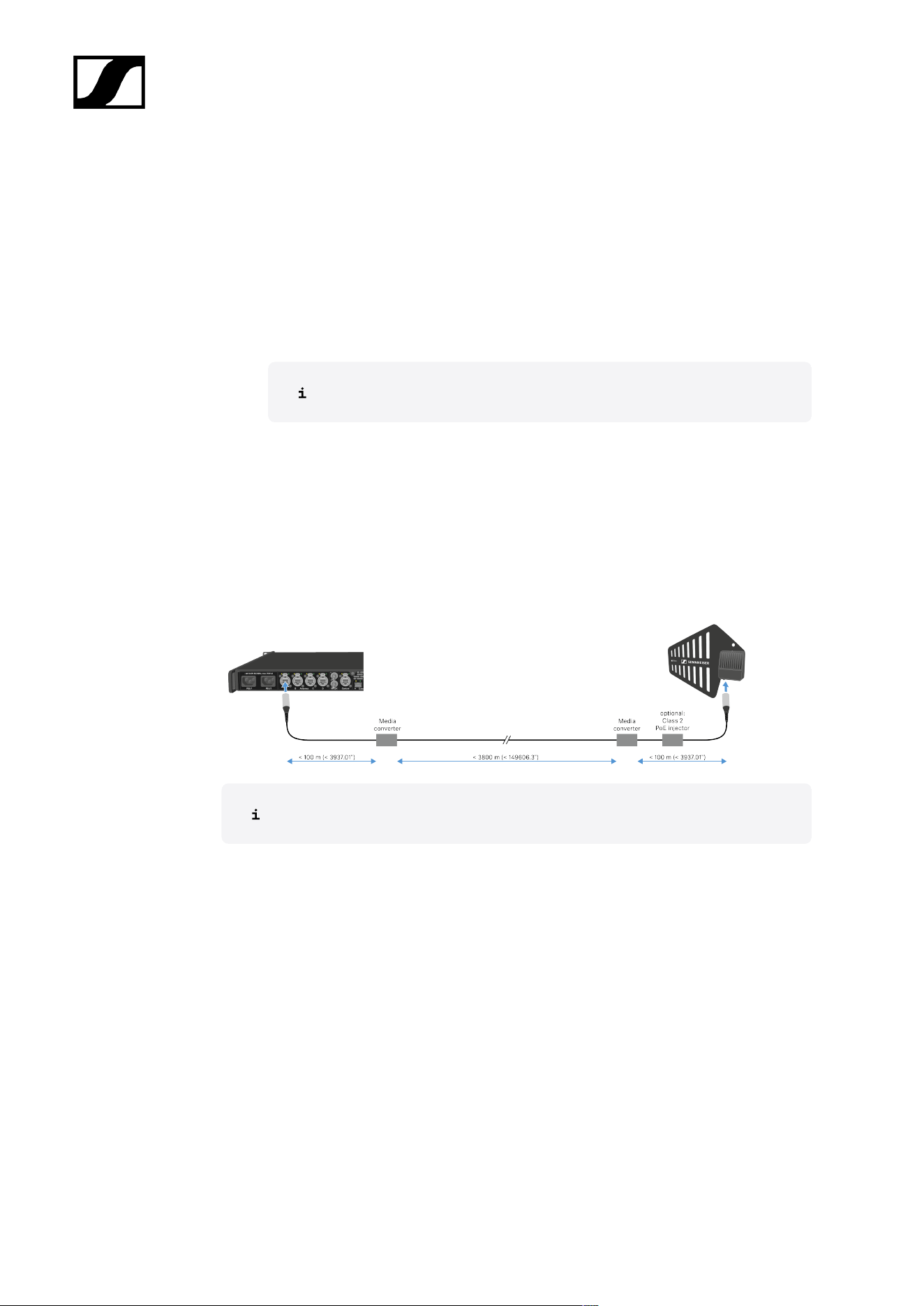
| 4 - Instruction manual
Antenna cable extension
Longer cable distances are possible with the use of fiber optic cables and media
converters.
Sennheiser tested the recommend converters for a complete distance of 4 km (157480.31").
We only recommend the following converters for fully tested functionality:
• Base Station:
Do not use converters with PoE to connect to the Base Station.
• Lantronix M/GE-T-SFP-01
• DAD:
• Lantronix M/GE-PSW-PSE-01 (with PoE only for DAD)
• Lantronix M/GE-T-SFP-01 (needs a Class 2 PoE injector capable of supplying
powering to the DAD (power consumption < 6.5 W))
• Barnfind Technologies BarnColor 4xEth (with PoE only for DAD)
• StarTech.com Industrial PoE Media Converter (Product ID: IMC1GSFP30W)
(with PoE only for DAD)
The media converter must not have a switch function.
217
| 4 - Instruction manual
Updating the DAD
The firmware of the antenna will update automatically, when connected to the Base Station.
NOTICE
Data loss during firmware update
The audio transmission is interrupted during the firmware update of the
Base Station, the antenna or the mobile device.
After the firmware update, the device is restarted automatically.
Do not update the firmware during an active live audio
transmission.
To update the firmware:
Connect the antenna to a Base Station. See Connecting/disconnecting the antenna.
To update the Base Station, see Updating the Base Station.
The LED is flashing green and red during the update.
The firmware has been updated.
218
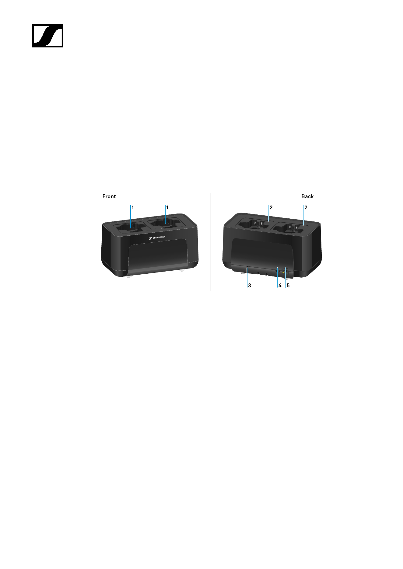
| 4 - Instruction manual
CHG 70N-C charger
The CHG 70N-C is a network enabled charger featuring two individual charging bays.
Compatible products:
• EW-DX SKM/EW-DX SKM-S handheld transmitter
• EW-DX SK/EW-DX SK 3-PIN bodypack transmitter
• SPECTERA SEK bidirectional transmitter
• BA 70 rechargeable battery
Product overview
1 Charging slots
• See Charging the rechargeable battery
2 Status LED of the charging slots
• See Charging the rechargeable battery
3 Reset button
• Press and hold for 10 seconds to reset the device’s network settings, see
Connecting a charger in a network
• Press and hold for 4 seconds to enable power saving mode, see Power saving
mode
4 DC in connection socket for the NT 12-35 CS power supply unit
• See Connecting/disconnecting the charger to/from the power supply system
219

| 4 - Instruction manual
5 PoE/Ethernet RJ45 socket for controlling the device over the network and for Power over
Ethernet power supply
• See Connecting a charger in a network
• See Connecting/disconnecting the charger to/from the power supply system
You can cascade up to 5 devices with only one power supply and one network
connection. See Cascading chargers.
220
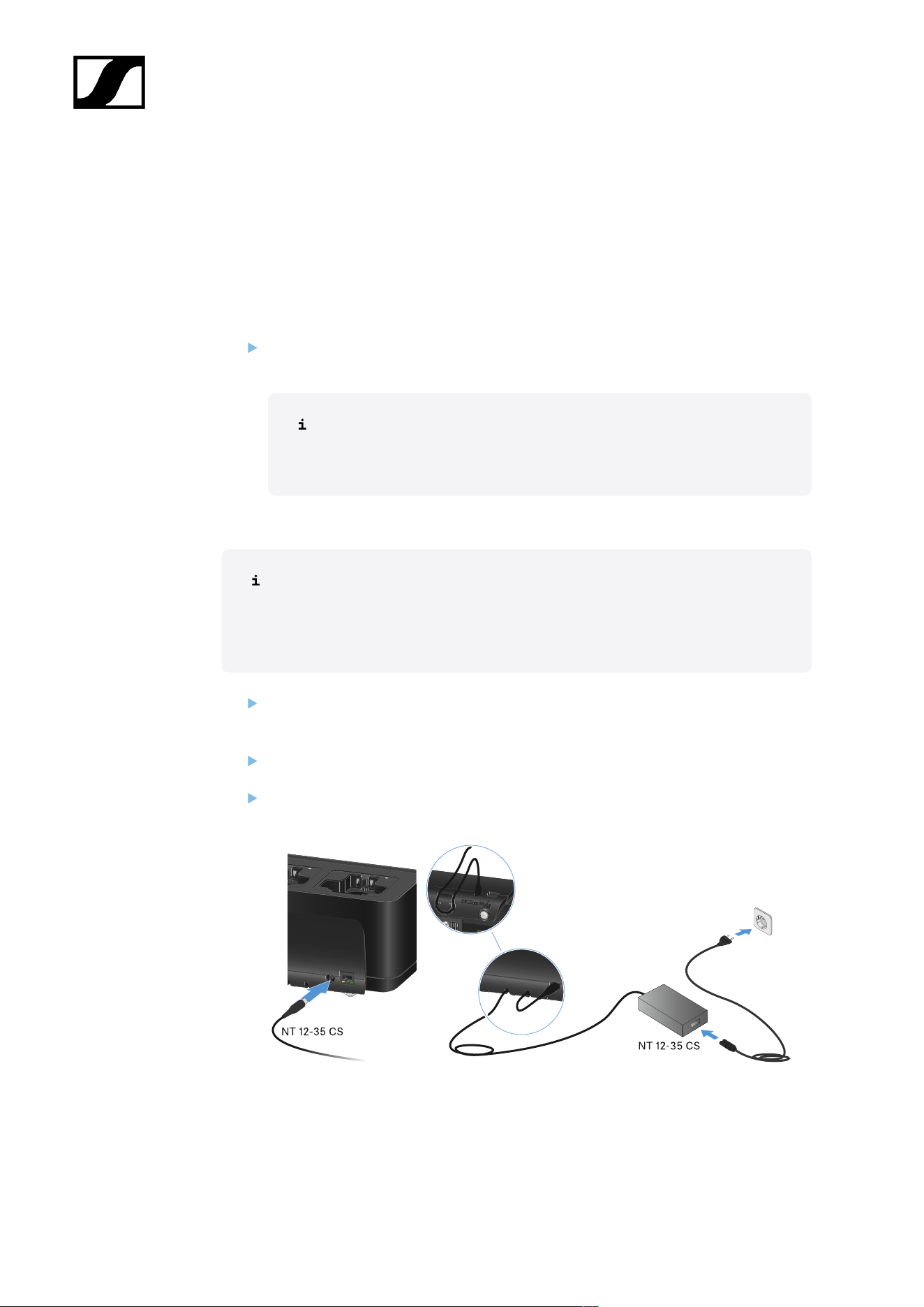
| 4 - Instruction manual
Connecting/disconnecting the charger to/from the power supply
system
You can operate the charger either with the Sennheiser NT 12-35 CS power supply unit
or with Power over Ethernet (PoE IEEE 802.3af Class 0). Please refer to the following
information.
Power from the NT 12-35 CS power supply unit
Use only the NT 12-35 CS power supply unit from Sennheiser. It is designed for your
charger and ensures safe operation.
The power supply unit is available either separately (Sennheiser article
number 508995) or together with the charger as a kit (see CHG 70N-C
network-enabled charger).
Power from the NT 12-35 CS power supply unit
Use only the NT 12-35 CS power supply unit from Sennheiser. It is designed
for your charger and ensures safe operation. The power supply unit is available
either separately (Sennheiser article number 508995) or together with the
charger as a kit (see CHG 70N-C network-enabled charger).
Connect the hollow jack plug of the power supply unit to the DC in socket on the
charger.
Pass the cable through the strain relief.
Plug the power supply unit into the wall outlet using the correct power cable for your
country.
221
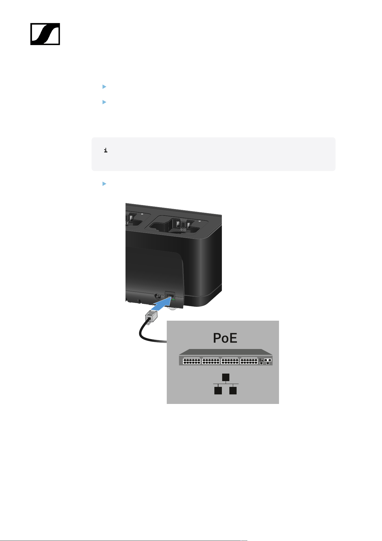
| 4 - Instruction manual
Disconnecting the charger completely from the power supply system
Unplug the mains cable from the wall socket.
Unplug the hollow jack plug of the power supply unit from the DC in socket on the
charger.
Power over Ethernet (PoE)
The charger can be powered via Power over Ethernet (PoE IEEE 802.3af Class
0).
Connect the charger to a PoE-enabled network switch.
222
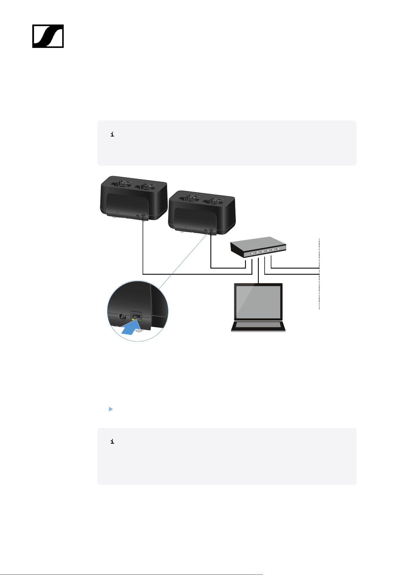
| 4 - Instruction manual
Connecting a charger in a network
You can monitor and control one or more chargers via a network connection using the
Sennheiser Control Cockpit (SCC) software.
The network does not have to be a homogeneous network including only
chargers. You can integrate the charger into your existing network infrastructure
with any other types of devices.
You can integrate the devices into the network individually or cascade up to 5 chargers (see
Cascading chargers).
To reset the network settings to their factory defaults:
Hold the Reset button for 4 seconds.
For more information about controlling devices via the Sennheiser Wireless
Systems Manager or Sennheiser Control Cockpit software, refer to the
instruction manual for the software. You can download the software here:
sennheiser.com/control-cockpit
223
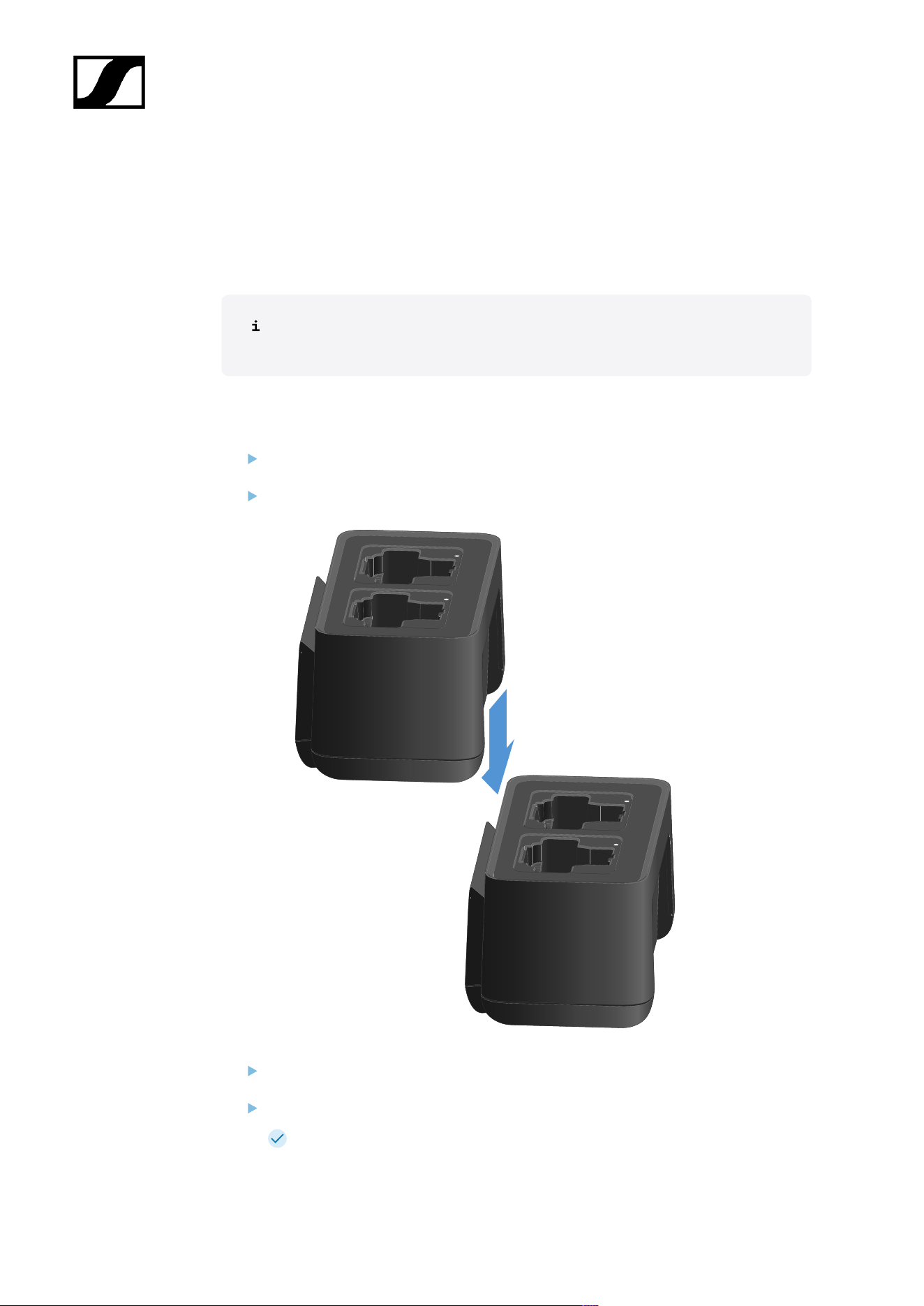
| 4 - Instruction manual
Cascading chargers
You can cascade up to five CHG 70N-C chargers and operate them with a single power
supply and a single network connection. This minimizes the cabling required for larger
systems.
The power must be supplied via the NT 12-35 CS power supply unit. Power over
Ethernet (PoE) is not possible when cascading.
To cascade the chargers:
Make sure that no chargers are connected to the power before you start.
Plug the chargers into each other as shown in the figure.
Detach the connecting rail on the bottom of the charger.
Fasten the connecting rail beneath two chargers as shown in the figure.
The power and the network connection are passed on to all devices via the
connecting rails.
224
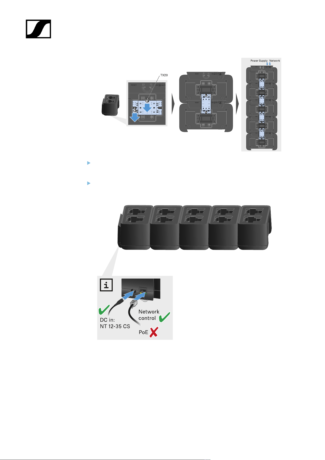
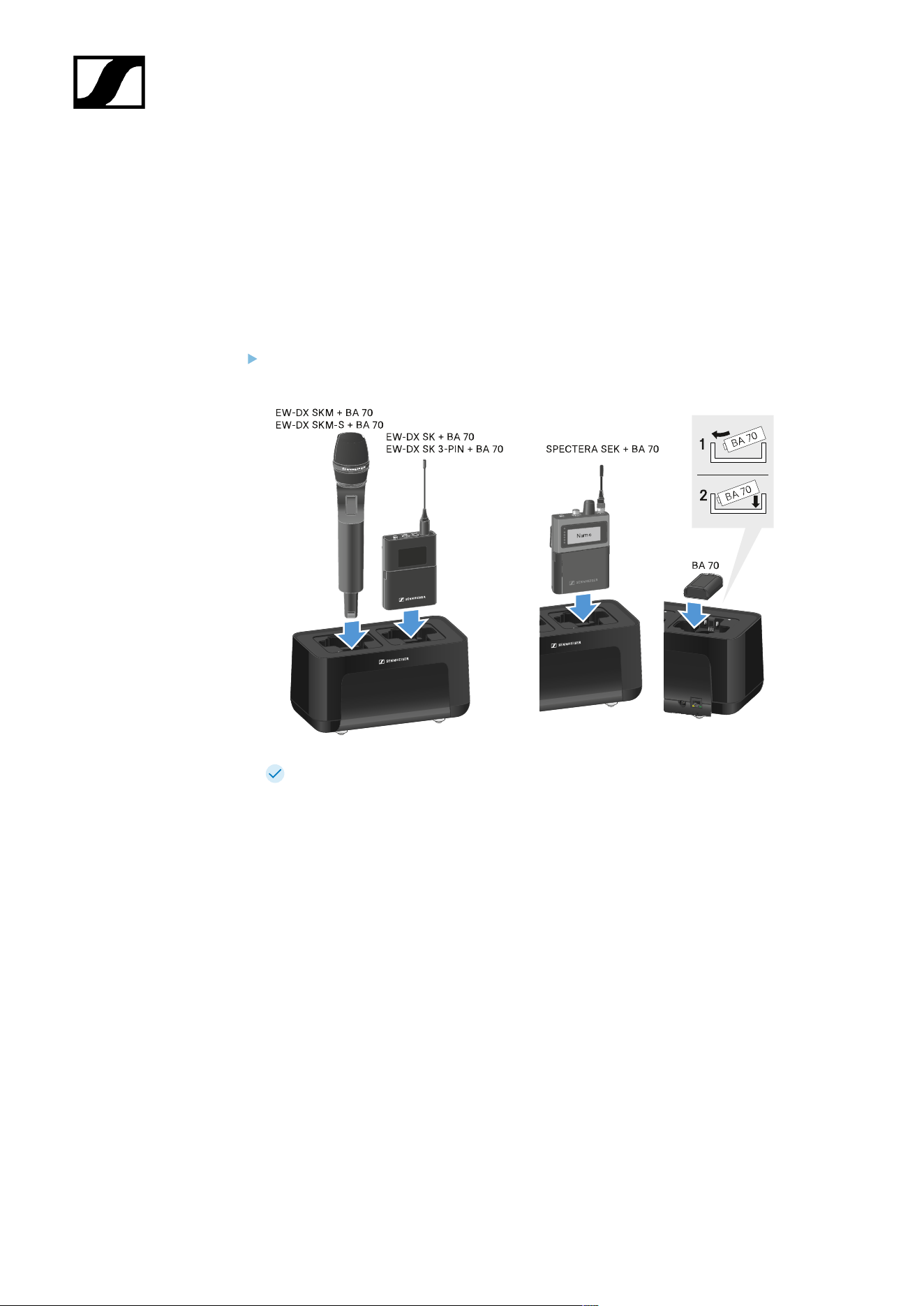
| 4 - Instruction manual
Charging the rechargeable battery
You can use the CHG 70N-C charger to charge individual BA 70 rechargeable batteries, or to
charge EW-DX SKM, EW-DX SKM-S, EW-DX SK, EW-DX SK 3-PIN or Spectera SEK with the
BA 70 rechargeable battery already inserted.
To charge the battery:
Insert the individual rechargeable battery or the transmitter with battery already
inserted into the charging slot as shown in the figure.
The rechargeable battery will begin charging.
The LED on the charging slot shows the battery’s charge level.
226
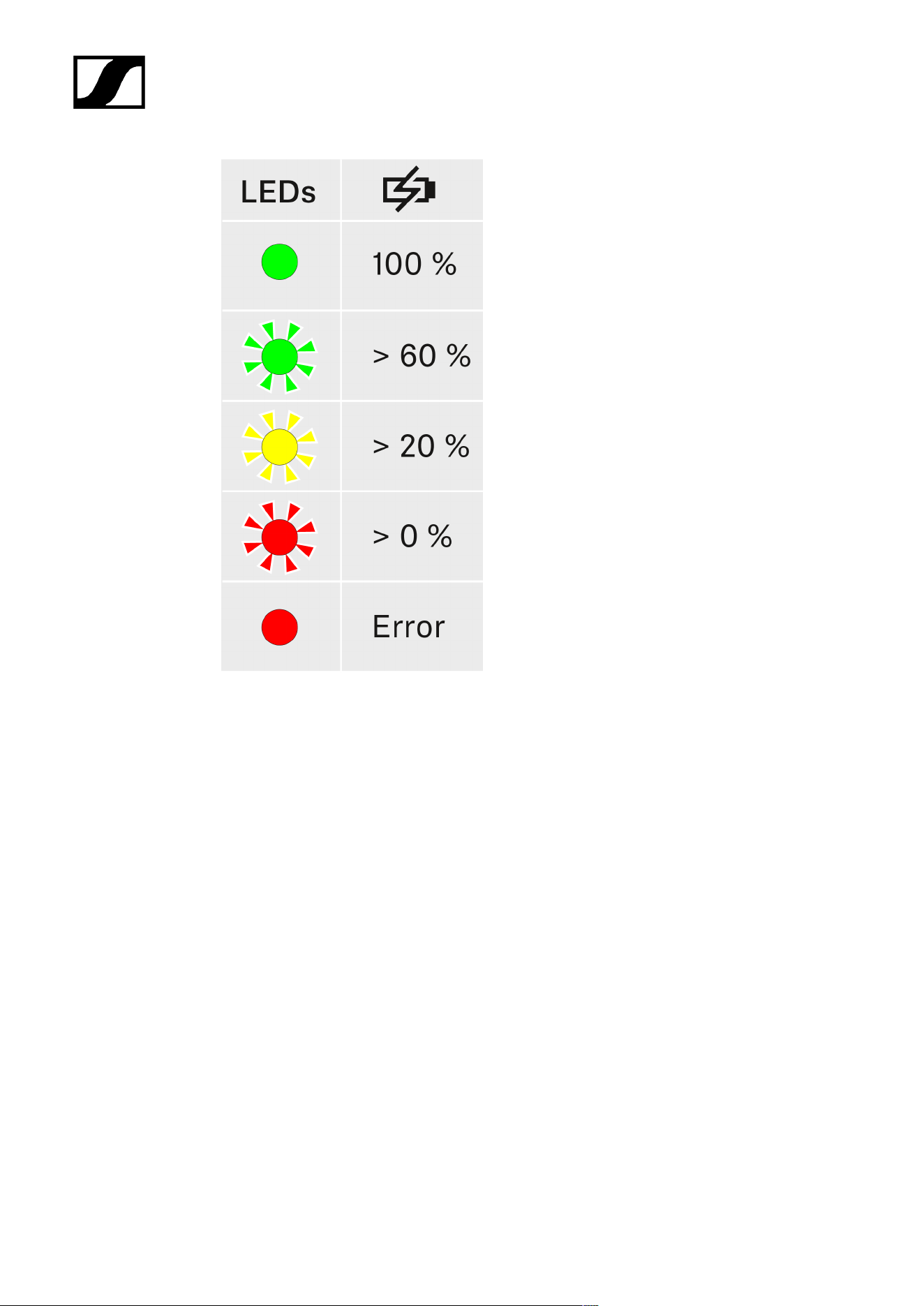
| 4 - Instruction manual
227

| 4 - Instruction manual
Power saving mode
In power saving mode, the transmitters are charged only once. The charger also does not
provide any trickle charge.
To activate power saving mode:
In power saving mode, the CHG 70N-C cannot be controlled over the network.
Remove all transmitters and/or rechargeable batteries from the charging slots.
Hold the Reset button for 4 seconds.
The charging slot LEDs light up purple.
Insert the rechargeable battery/transmitter for charging.
The rechargeable battery will begin charging. The charging slot LED turns green
once it reaches full charge.
To deactivate power saving mode:
Disconnect the charger from the power supply system.
Then reconnect it to the power supply system.
The charger will start up in the configuration that was set before you activated
power saving mode.
228

| 4 - Instruction manual
Updating the firmware of the charger
You can update the charger firmware using the Sennheiser Control Cockpit software.
229

| 4 - Instruction manual
Note on firmware version 4.0.0
Devices with outdated firmware can no longer be reached in a cascade if the first
charger has the new firmware.
Disconnect the chargers from the cascade.
Update the firmware of each charger individually.
Connect the chargers.
230

| 4 - Instruction manual
Updating with the Sennheiser Control Cockpit:
Connect the charger to a network (see Connecting a charger in a network) and
establish the connection with the software.
For more information about controlling devices with the Sennheiser
Control Cockpit software, refer to the software help.
You can download the software here:
sennheiser.com/control-cockpit
231
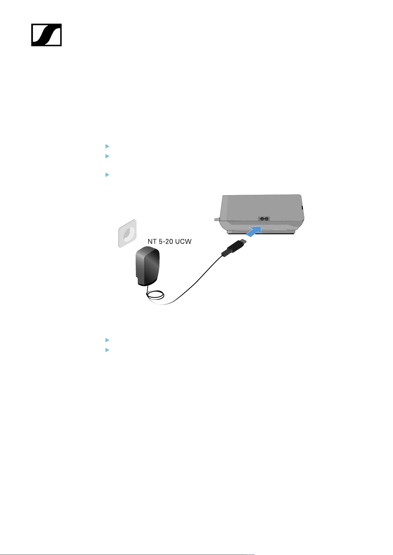
| 4 - Instruction manual
L 70 USB charger
Connecting/disconnecting the charger to/from the power supply
system
To connect the charger to the power supply system:
Use only the NT 5-20 UCW power supply unit from Sennheiser.
Connect the USB-C plug on the charging cable to the USB-C port on the side of the
charger.
Plug the power supply unit with the correct country adapter into a suitable power
outlet.
To disconnect the charger from the power supply system:
Unplug the power supply unit from the wall socket.
Remove the USB-C plug on the charging cable from the USB-C port on the side of the
charger.
232
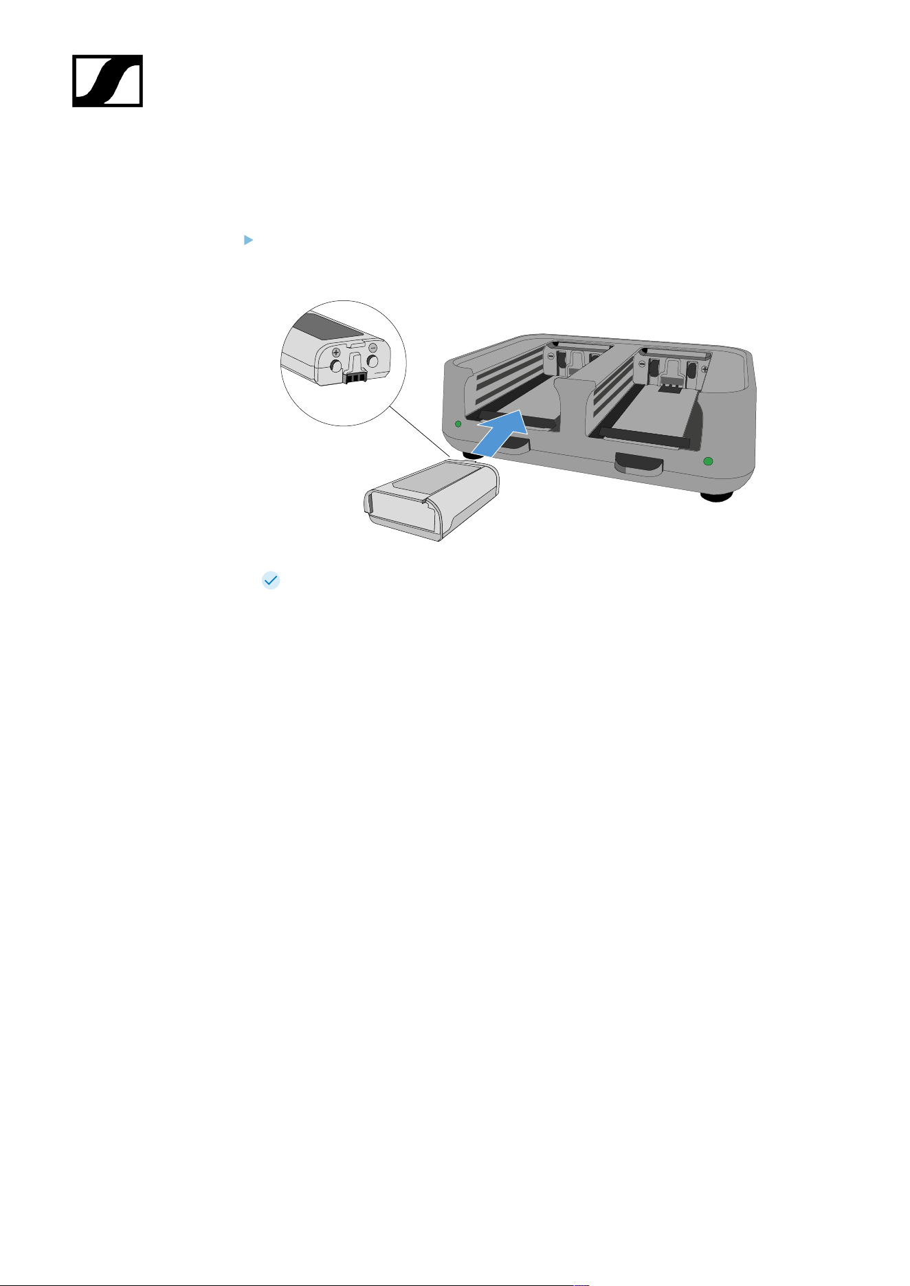
| 4 - Instruction manual
Charging the rechargeable battery
To charge the BA 70 rechargeable battery in the L 70 USB charger:
Slide the rechargeable battery completely into the charging slot as shown in the
figure.
The rechargeable battery will begin charging.
The LED on the charging slot shows the battery’s charge level:
233
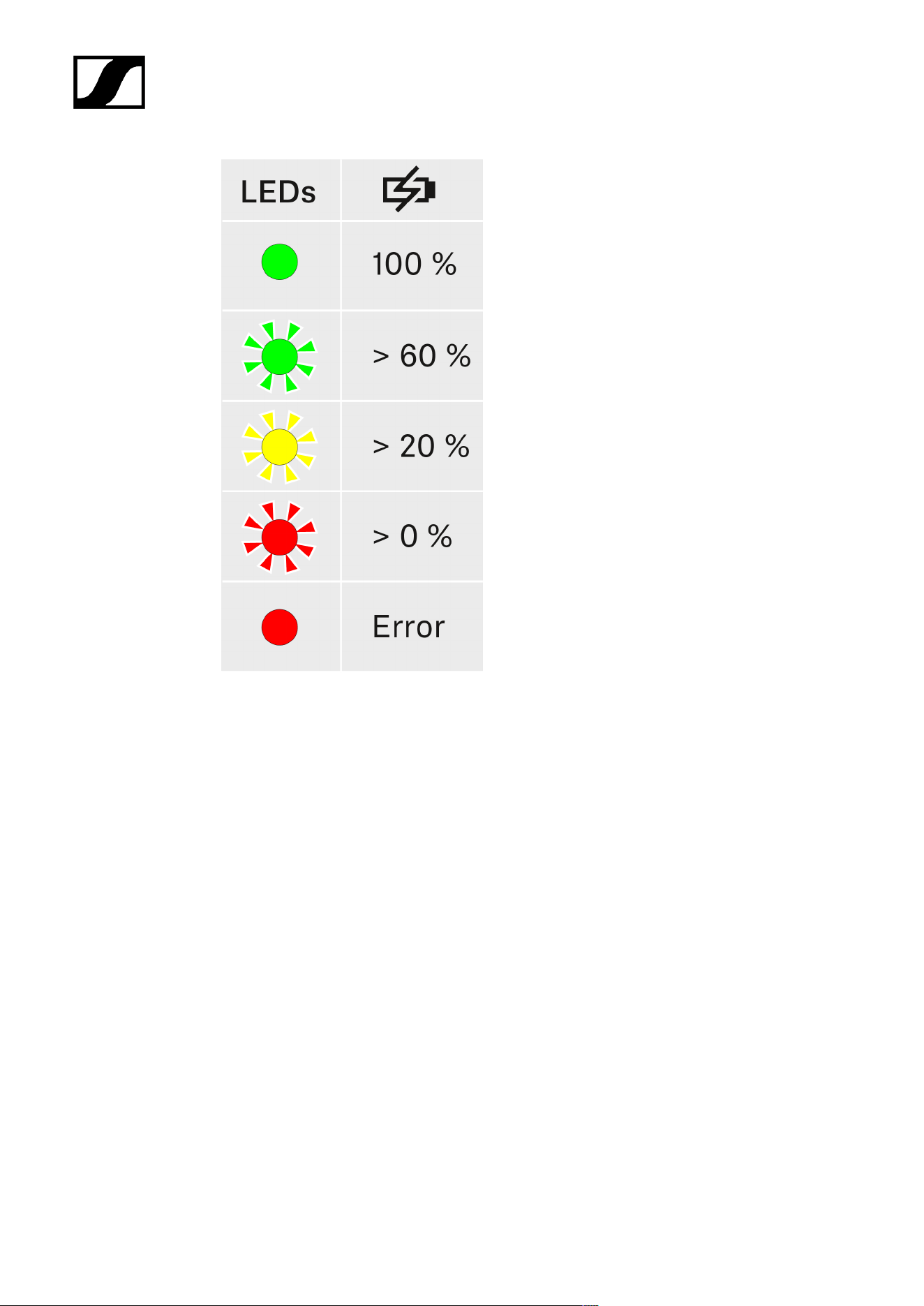
| 4 - Instruction manual
234
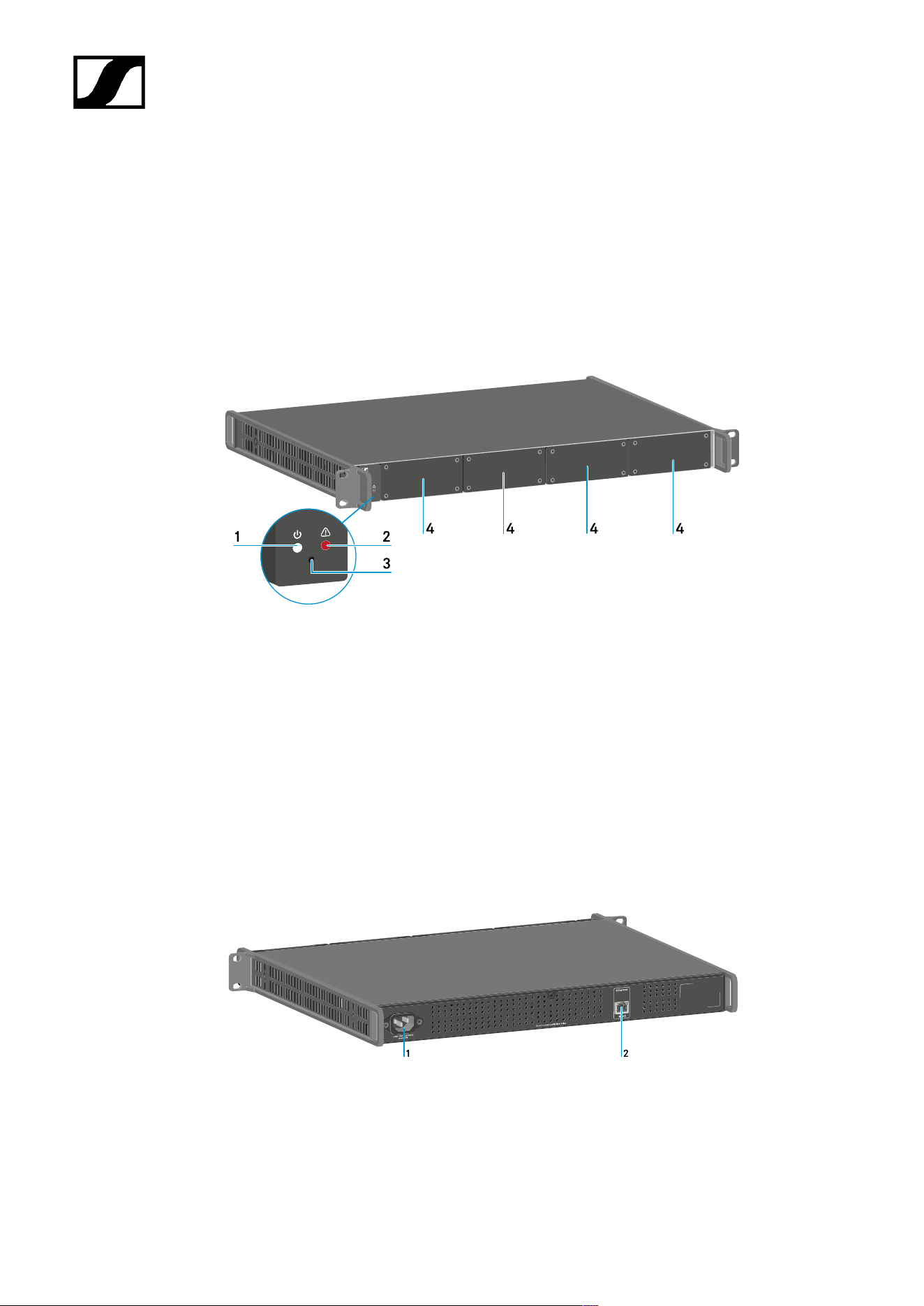
| 4 - Instruction manual
Modular L 6000 charger
These sections contain information about installing, starting up and operating the modular
L 6000 charger and the corresponding charging modules.
Product overview
Front
1 Power status LED
See Meaning of the LEDs
2 Warning status LED
See Meaning of the LEDs
3 Reset
See Resetting settings (factory reset)
4 Dummy caps
See Installing a charging module in the L 6000 charger
Back
1 Power socket
See Connecting/disconnecting the L 6000 to/from the power supply system
2 Ethernet socket
See Connecting the L 6000 to a network
235
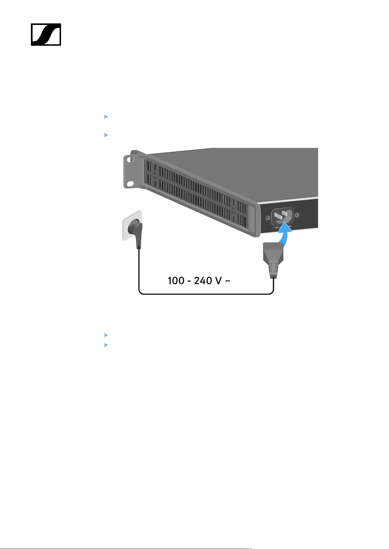
| 4 - Instruction manual
Connecting/disconnecting the L 6000 to/from the power supply
system
To connect the L 6000 to the power supply system:
Connect the mains cable IEC connector to the power socket on the rear side of the L
6000.
Connect the mains cable plug into a suitable wall socket.
To completely disconnect the L 6000 from the power supply system:
Unplug the mains cable plug from the wall socket.
Unplug the mains cable IEC connector from the power socket on the rear side of the L
6000.
236
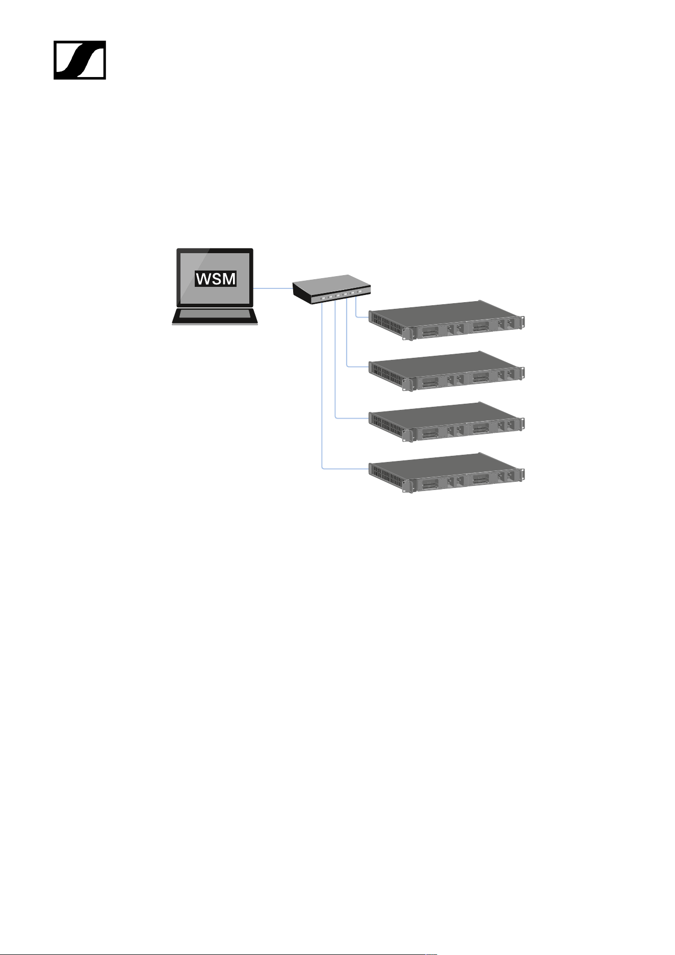
| 4 - Instruction manual
Connecting the L 6000 to a network
You can monitor and control one or more L 6000s via a network connection using the
Sennheiser Wireless Systems Manager (WSM) software.
The network does not have to be a homogeneous network including only chargers. You can
integrate the L 6000 into your existing network infrastructure with any other types of devices.
237
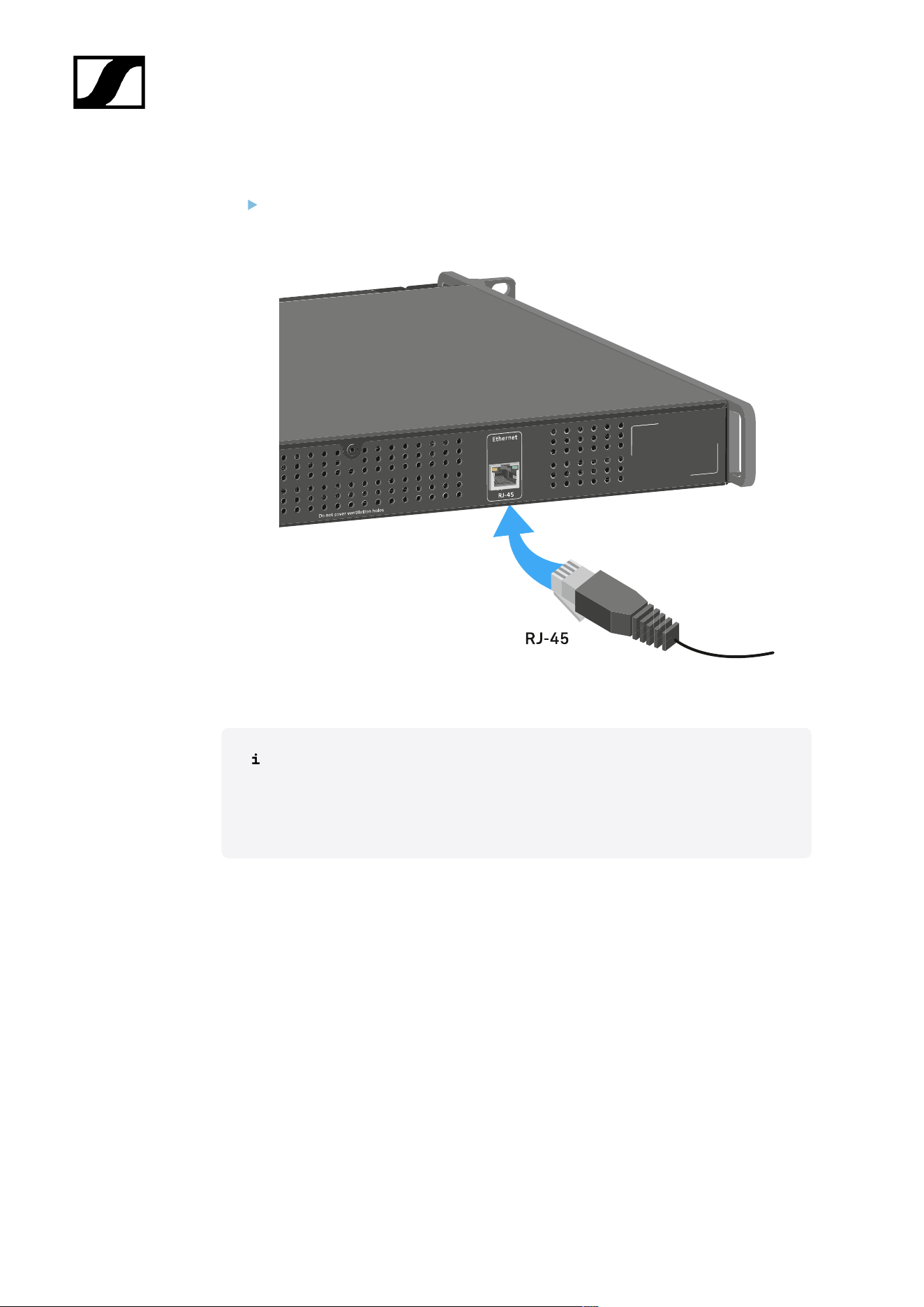
| 4 - Instruction manual
To connect the L 6000 to a network:
Connect a network cable with an RJ-45 connector (Cat5 at minimum) to the Ethernet
socket on the rear side of the L 6000.
For more information about controlling devices via the Sennheiser Wireless
Systems Manager (WSM) software, refer to the instruction manual for the
software. You can download the software here:
sennheiser.com/wsm
238
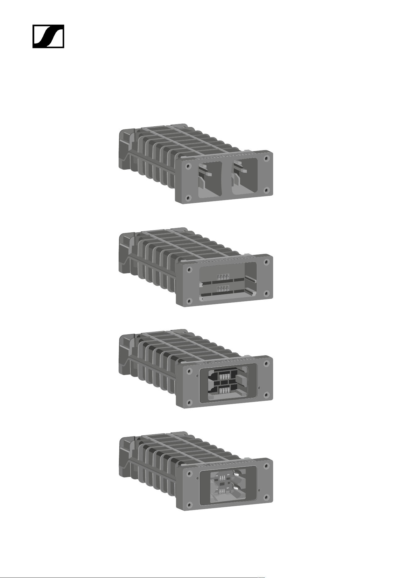
| 4 - Instruction manual
Installing a charging module in the L 6000 charger
The following charging modules are available for the L 6000 charger.
• LM 6060 -> for charging the BA 60 rechargeable battery
• LM 6061 -> for charging the BA 61 rechargeable battery
• LM 6062 -> for charging the BA 62 rechargeable battery
• LM 6070 -> for charging the BA 70 rechargeable battery
239
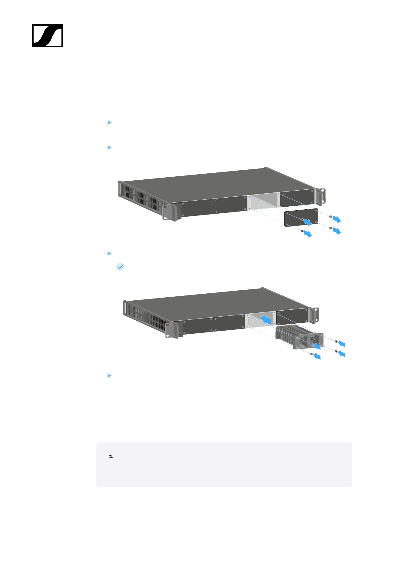
| 4 - Instruction manual
You can combine the LM 6060, LM 6061, LM 6062 and LM 6070 in any way in the L 6000
charger.
To install a charging module in the L 6000 charger:
Completely disconnect the L 6000 charger from the power supply system. See
Connecting/disconnecting the L 6000 to/from the power supply system.
Unscrew one of the dummy caps on the L 6000.
To do so, you require a Torx 10 screwdriver.
Fully slide the charging module into the open charging slot as shown in the figure.
The charging module can be inserted into the L 6000 housing only in one
direction. The Sennheiser lettering on the charging module must face upward.
Tightly screw on the charging module.
Always use the latest firmware for the L 6000 charger (version 2.0 or later) to ensure you
have access to the full range of functions. You can download the latest firmware from the
following address:
sennheiser.com/l-6000
For more detailed information about charging the BA 60, BA 61 and BA 62 and
BA 70 rechargeable batteries, see Charging the rechargeable batteries in the
L 6000 charger.
240
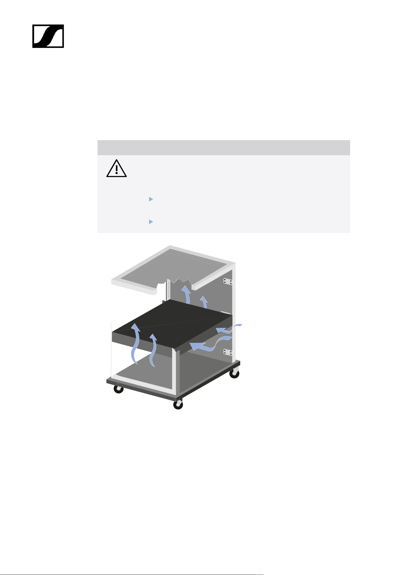
| 4 - Instruction manual
Installing the L 6000 in a rack
You can install the L 6000 charger in any conventional 19" rack.
The rack mounting angles are already attached to the device.
Always observe the following information during rack mounting.
NOTICE
Material damages caused by devices overheating
When there is insufficient ventilation, the devices mounted in the rack
may overheat.
Ensure that there is sufficient ventilation in the rack, particularly
if several devices are installed.
If necessary, install a fan in the rack.
241
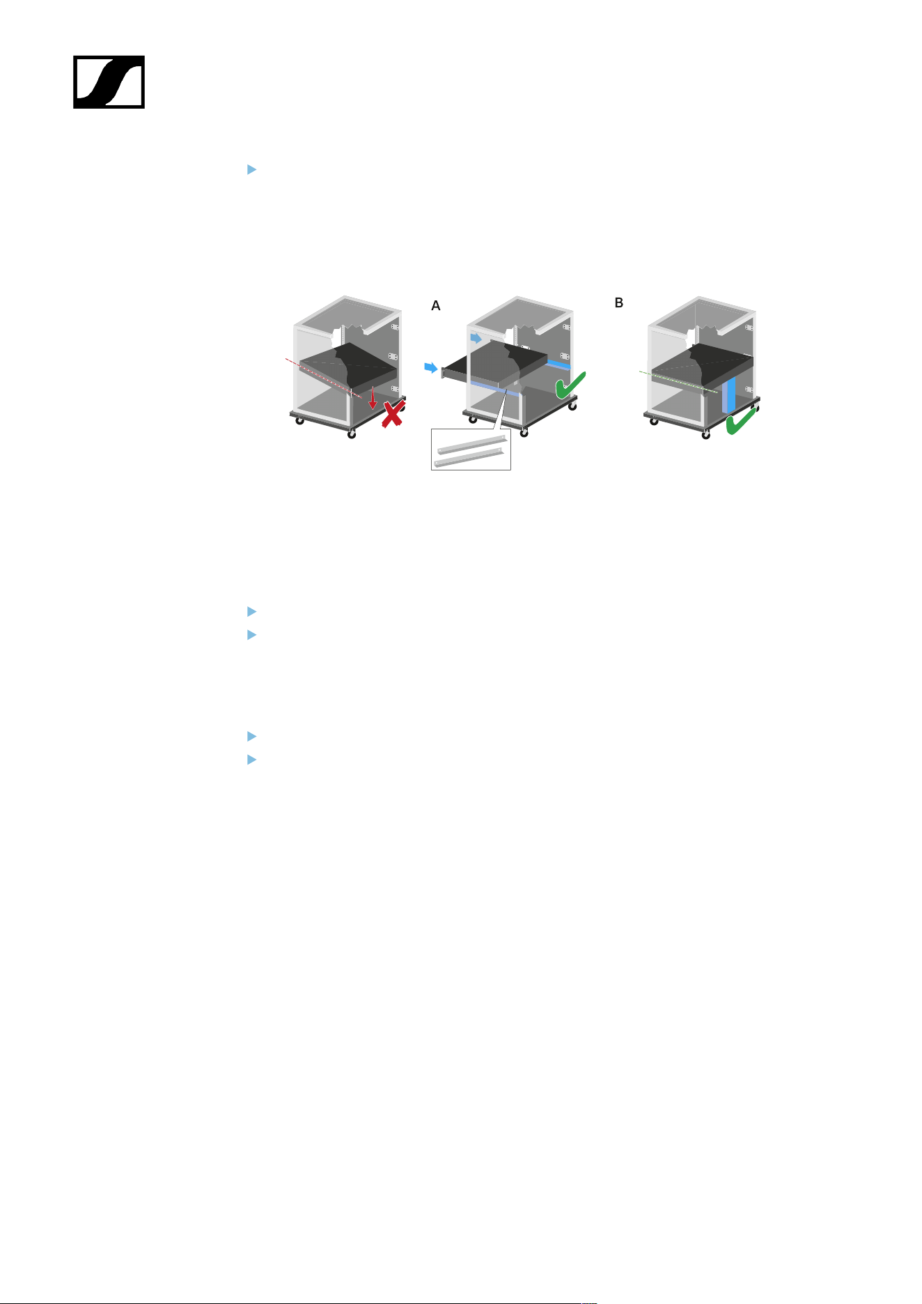
| 4 - Instruction manual
Support the EM 6000 after installation in the rack. Due to the weight and depth of
the device, there is a risk that it may break off in the rack and become damaged as a
result.
Version A:
Use special rack mounting rails.
The design of the rack used must be suitable for the installation of these mounting
rails.
Version B:
Use a suitable object to support the device on the rear side.
Ensure that this object cannot become loose.
242

| 4 - Instruction manual
Charging the rechargeable batteries in the L 6000 charger
To charge the BA 60, BA 61, BA 62 and BA 70 rechargeable batteries with the L 6000
charger, you need the LM 6060, LM 6061, LM 6062 or LM 6070 charging modules.
Before charging, you have to install the charging modules in the L 6000 charger. For
installation information, see Installing a charging module in the L 6000 charger.
Note on the charger firmware
Always use the latest firmware for the L 6000 charger (version 2.0 or later) to
ensure you have access to the full range of functions. You can download the
latest firmware from the following address:
sennheiser.com/l-6000
Note on the BA 62 rechargeable battery for the SK 6212 bodypack transmitter
It is possible that new rechargeable batteries cannot be fully charged to 100 %
in the first few charging cycles.
The remaining operating time may still be unclear after the first few charging
cycles. This will improve over time after more charging cycles because the
rechargeable battery calibrates itself.
NOTICE
Damage to the charging contacts in the charging slot
If you touch the contacts in the charging slot, they may become dirty or
bent.
When replacing and removing the rechargeable batteries, ensure
that you do not touch the charging contacts in the charging slots.
244
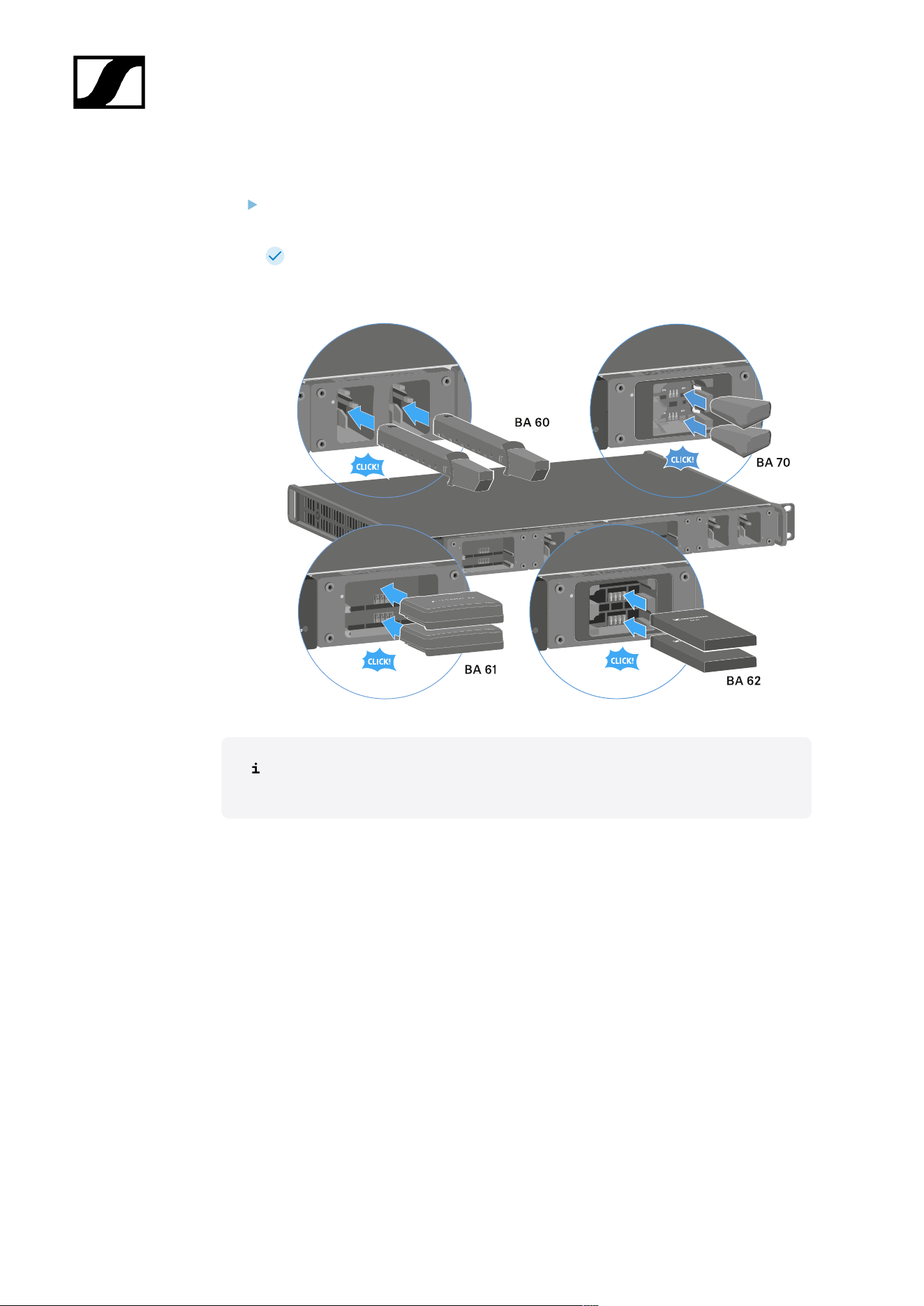
| 4 - Instruction manual
To charge the rechargeable batteries:
Insert the rechargeable battery into the charging module as shown in the figure until it
audibly clicks into place.
The rechargeable batteries can be inserted into the charging modules only in one
direction. You can see the charge level of the rechargeable batteries from the
LEDs on the charging modules (see Meaning of the LEDs).
At ambient temperatures of 45° C (113° F) and above, the rechargeable batteries
can no longer be fully charged. They can only be charged to a maximum of 70 %.
245
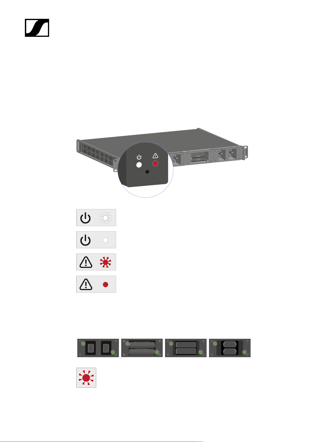
| 4 - Instruction manual
Meaning of the LEDs
You can read the following information from the LEDs on the L 6000 charger and the LM
6060, LM 6061, LM 6062 and LM 6070 charging modules:
L 6000 status LEDs
The L 6000 charger has two status LEDs on the front of the device to the left.
White LED flashing >> device is starting or firmware is being updated
White LED illuminated >> device is ready for operation
Red LED flashing >> fan is damaged
Red LED illuminated >> device is too hot or too cold and the charging
process was stopped
LM 6060 | LM 6061 | LM 6062 | LM 6070 status LEDs
The LM 6060, LM 6061, LM 6062 and LM 6070 modules each have two charging slots. Next
to each charging slot, there is a status LED that displays the following status information:
Flashing red >> the charging slot or rechargeable battery is too hot or too cold
and the charging process was stopped.
246
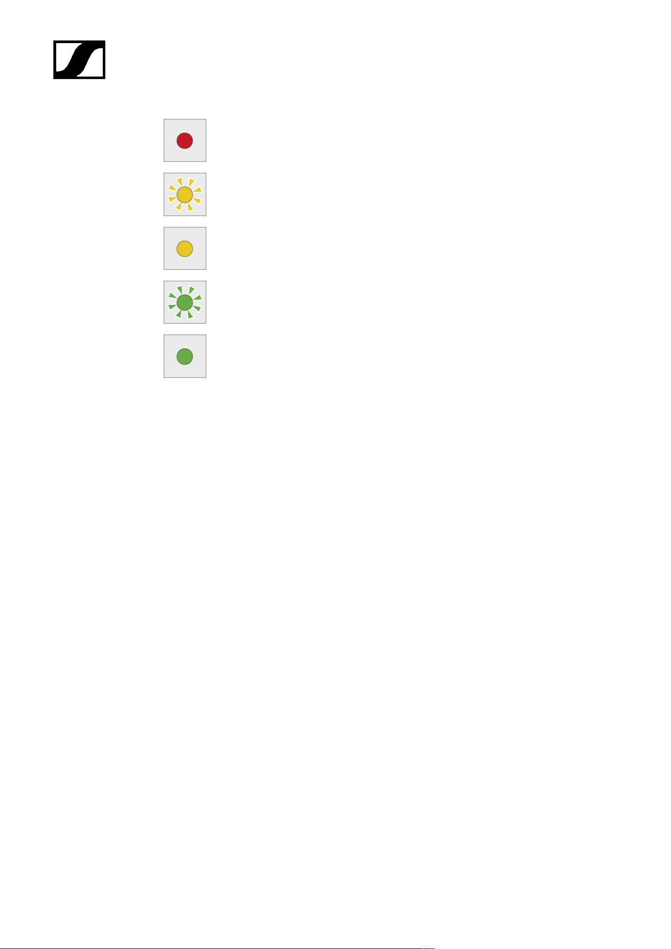
| 4 - Instruction manual
Lights up red >> the rechargeable battery is defective.
Flashing yellow >> the rechargeable battery is being regenerated.
Lights up yellow >> the rechargeable battery is being charged. Charge level 0%
to 80%
Flashing green >> the rechargeable battery is being charged. Charge level 81%
to 96%
Lights up green >> the rechargeable battery is fully charged. Charge level 100%
LM 6060, LM 6061, LM 6062 and LM 6070 status LEDs in storage mode
If you are operating the L 6000 charger in storage mode via WSM, the meaning of the status
indicators changes. You can find more information under Preparing rechargeable batteries
for storage (storage mode).
247
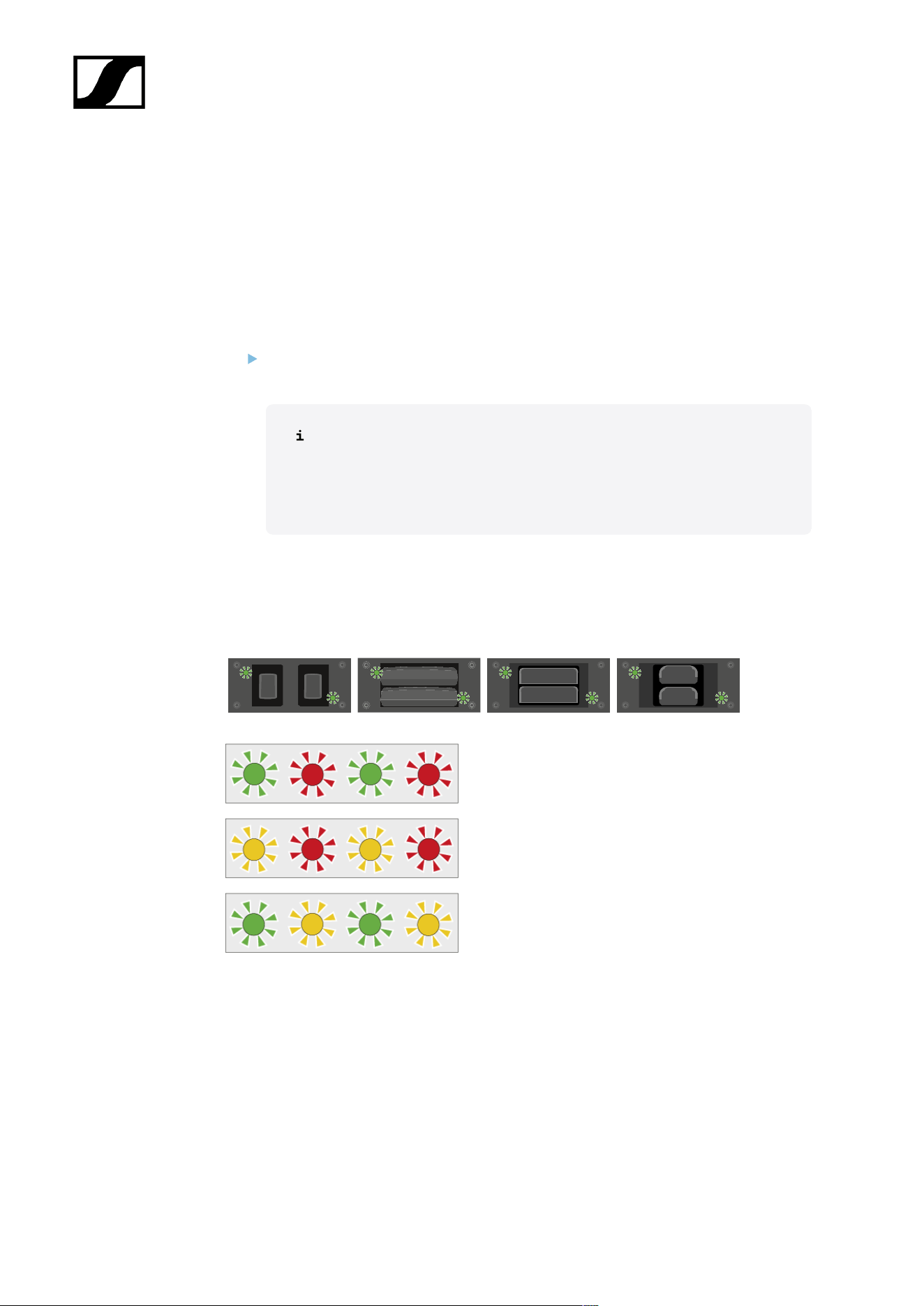
| 4 - Instruction manual
Preparing rechargeable batteries for storage (storage mode)
If you are not using the rechargeable batteries for a longer period of time and therefore want
to store them, the rechargeable batteries should have a charge of approx. 70%.
You can set this level using the storage mode from the Sennheiser Wireless Systems
Manager (WSM) software.
To do so, connect the L 6000 charger to a network (see Connecting the L 6000 to a
network) and establish the connection with the WSM software.
For more information about controlling devices via the Sennheiser
Wireless Systems Manager (WSM) software, refer to the instruction
manual for the software. You can download the software here:
sennheiser.com/wsm
Meaning of the status LEDs in storage mode
In storage mode, the status LEDs next to the individual charging slots show the following
status information:
Flashing green/red >> rechargeable battery not
inserted.
Flashing yellow/red >> the rechargeable battery is
being charged or discharged to 70%.
Flashing green/yellow >> the rechargeable battery
has reached the storage charge level of 70%.
248
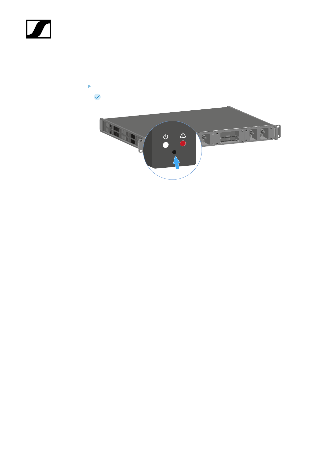
| 4 - Instruction manual
Resetting settings (factory reset)
To reset the L 6000 charger settings to the factory settings:
Use a pointed object to press the Reset button on the front of the L 6000 charger.
The settings are reset to the factory settings.
249

| 4 - Instruction manual
Updating the firmware
You can update the firmware for the L 6000 charger using the Sennheiser Wireless Systems
Manager (WSM) software.
To do so, connect the L 6000 charger to a network (see Connecting the L 6000 to a
network) and establish the connection with the WSM software.
For more information about controlling devices via the Sennheiser
Wireless Systems Manager (WSM) software, refer to the instruction
manual for the software. You can download the software here:
sennheiser.com/wsm
You can find the latest firmware on the Digital 6000 product page or in the
Sennheiser website’s download area:
sennheiser.com/digital-6000
sennheiser.com/download
250

| 4 - Instruction manual
Operating the L 6000 via a network
You can use the Sennheiser Wireless Systems Manager software to operate the charger via
a network connection.
To do so, connect the L 6000 charger to a network (see Connecting the L 6000 to a
network) and establish the connection with the WSM software.
For more information about controlling devices via the Sennheiser
Wireless Systems Manager (WSM) software, refer to the instruction
manual for the software. You can download the software here:
sennheiser.com/wsm
You can perform the following actions using WSM:
• Update the L 6000 charger firmware
• Prepare rechargeable batteries for storage (see Preparing rechargeable batteries for
storage (storage mode)).
251
| 4 - Instruction manual
Cleaning and maintenance
Note the following information when cleaning and maintaining products of the Spectera
series.
NOTICE
Liquids can damage the electronics of the product
Liquids entering the product housing can cause a short-circuit and
damage the electronics.
Keep all liquids away from the products.
Do not use any solvents or cleansing agents.
Disconnect the mains-operated products from the power supply
system and remove rechargeable batteries and batteries (if
present) before you begin cleaning.
Clean all products only with a soft, dry cloth.
Note the special cleaning instructions below for the following products.
Replacing the Base Stations fan filter
Check the filter from time to time and replace it if necessary. See Changing the fan
filter.
Cleaning the L 70 USB and CHG 70N-C chargers
Remove all rechargeable batteries from the charging slots.
Disconnect the charger from the power supply system before cleaning.
Clean the product with a dry cloth.
In addition, use a brush to remove dust from the charging slots.
Clean the charging contacts from time to time with a cotton swab, for instance.
252

Spectera
5. Knowledge base
Central hub for information, resources, and guides with further content on the product and/
or service.
This page provides an overview of all additional information such as guides, know-how, best
practices, and further links related to the product.
Helpful links
• sennheiser.com/spectera
PDF downloads
For all PDF downloads, please refer to the page Knowledge base.
Troubleshooting
This chapter provides a systematic approach for identifying and resolving issues that may
occur during the startup or operation of Spectera.
Depending on the specific problem, click on the relevant chapter to identify possible causes
and apply potential solutions.
License activation fails
Condition
An error occurs during license activation.
Causes
The three most common causes of activation errors are as follows:
1. The Base Station was not connected properly and has no Internet connection (see
Solution 1: Establish a proper connection of the Base Station to the Internet).
2. The license server and/or NTP time server are/is unreachable due to missing port
permissions, preventing license key authorization and system clock synchronization
(see Solution 2: Open required ports for license activation and system clock
synchronization).
3. The license key was entered incorrectly or has already been activated and is in use
with another Base Station (see Solution 3: Check the activation code and contact
support if necessary).
253
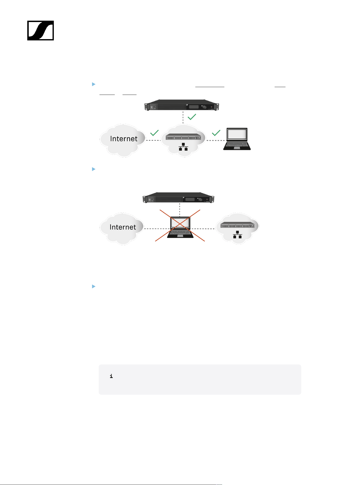
| 5 - Knowledge base
Solution 1: Establish a proper connection of the Base Station to the Internet
Please connect the Base Station directly to a network with Internet access via a
switch or router.
Direct connections via laptop etc. are only supported in certain network configuration
(see Sharing Internet connection in small network setups). To eliminate this issue,
please avoid a direct connection with your device for license activation.
Solution 2: Open required ports for license activation and system clock
synchronization
Please contact your IT administrator to provide Internet access to the License Server
and any NTP server by opening the required network ports and to provide DNS
settings via DHCP to the device.
Address Port Protocol Type Service Usage
my.nalpeiron.com 80 HTTPS
(TCP)
Unicast Sennheiser
License Server
Activation of
devices
ANY (see list of NTP
servers)
123 NTP Unicast NTP Time
Server
Synchronize
system time
You can find the complete overview of all ports at Ports, protocols and
services.
254

| 5 - Knowledge base
Solution 3: Check the activation code and contact support if necessary
Please verify that you have correctly entered the Activation Code, or check if someone
else has already used the code to activate another Base Station.
If the code has already been used for activation, please reach out to Sennheiser
Customer Support.
255

| 5 - Knowledge base
No device access via the WebUI
Condition
The device cannot be accessed via the self-hosted WebUI.
Cause
The wrong device IP or URL schema is being used in the browser.
Solution
Find out the correct IP of the Base Station (see Network).
To start the Spectera WebUI, enter the following URL into your browser: https://
deviceIP/ .
In some cases the internet browser might have trouble showing the page.
256

| 5 - Knowledge base
The Base Station cannot be found
Condition
The Base Station cannot be found via WebUI / Dante Manager.
Cause
The required ports for communication with the Base Station have not been made accessible.
Solution
Depending on the use case, please make the necessary ports available for the Base
Station, so that data traffic can flow unrestricted:
• Spectera Base Station
• Dante®
257

| 5 - Knowledge base
Interference noise with old RF devices
Condition
Other devices are disturbed or produce audible interference noise.
Cause
Old devices do not have good RF shielding.
Solution
Increase the distance between the devices.
258

| 5 - Knowledge base
Noise in the audio signal
Condition
Noise may occur in the audio signal of the SEK at the MIC/Line input.
Cause
Insufficient shielding of microphones or instrument cables.
Solution
Use microphones or instrument cables with sufficient shielding.
259

Spectera
6. Specifications
All technical data, system requirements and frequencies at a glance.
Spectera System
Transmission scheme
• Multicarrier, TDMA, TDD
RF channel
• Bandwidth: 6 or 8 MHz countrywise limited
• Mobiles devices: up to 128 per RF channel
• Audio links: up to 128 per RF channel
Radio frequency range
• UHF: 470 - 608 MHz, 630 - 698 MHz
• 1G4: 1350 - 1400 MHz, 1435 - 1525 MHz
• countrywise limited
Audio frequency response
• 20 Hz to 20,000 Hz (±1 dB) (Audio link modes with SeDAC and PCM audio codecs
only)
Encryption
• AES 256 CTR Mode exp. >10k years
Audio link modes
MIC/LINE Mono Max links per RF
carrier
Utilized % of RF
carrier
Audio
codec
La
tency
Range
Raw Low
Latency
Mono 8 12.5 % PCM 1.0 ms Redu
ced
Raw Mono 16 6.25 % PCM 1.6 ms Redu
ced
Live Low
Latency
Mono 8 12.5 % SeDAC 1.0 ms Exten
ded
Live Mono 16 6.25 % SeDAC 1.6 ms Exten
ded
Live Link
Density
Mono 32 3.13 % SeDAC 2.7 ms Stand
ard
260

| 6 - Specifications
MIC/LINE Mono Max links per RF
carrier
Utilized % of RF
carrier
Audio
codec
La
tency
Range
Max Range Mono 16 6.25 % OPUS 9.9
ms
Maxi
mum
Max Link
Density
Mono 128* 0.78 % OPUS 15.2
ms
Redu
ced
IEM/IFB Mono/
Stereo
Max links per RF
carrier
Utilized % of RF
carrier
Audio
codec
La
ten
cy
Range
Live Mono 16 6.25 % SeDAC 1.6
ms
Exten
ded
Live Link
Density
Mono 32 3.13 % SeDAC 2.7
ms
Stand
ard
Max Range Mono 16 6.25 % OPUS 9.9
ms
Maxi
mum
Max Link
density
Mono 128* 0.78 % OPUS 15.2
ms
Redu
ced
Live Ultra Low
Latency
Stereo 4 (8 ch) 25 % SeDAC 0.7
ms
Exten
ded
Live Low
Latency
Stereo 8 (16 ch) 12.5 % SeDAC 1.1 ms Exten
ded
Live Stereo 16 (32 ch) 6.25 % SeDAC 1.6
ms
Stand
ard
Live Link
Density
Stereo 32 (64 ch)** 3.13 % SeDAC 2.7
ms
Redu
ced
* Base Stations have 32 audio outputs, for 128 links in a single RF channel, 4 Base Stations
and firmware update with cascade port function are required (future release)
** Base Stations have 32 audio inputs, for 32 stereo links (64 ch) in a single RF channel, 2
Base Stations and firmware update with cascade port function are required (future release)
261

| 6 - Specifications
Base Station
General
RF channels
• 2
Audio inputs and outputs
• Input: up to 32 channels
• Output: up to 32 channels
• Individually selectable from digital audio interfaces
Digital audio inputs and outputs
• Dante®
• Ethernet, 1 Gbit/s
• 2× ruggedized RJ45 (Primary and Secondary)
• 32 In, 32 Out, 48 kHz or 96 kHz, 16/24/32 bit
• MADI (AES10)
• 2× Expansion Slots for MADI Card OM (optical fiber multimode) or MADI Card
BNC (separate accessories)
• 32 In, 32 Out, 48 kHz or 96 kHz, 16/24 bit
• Individual sample rate for each interface
Headphone output
• 6.3 mm jack
• 2× 50 mW at 32 Ω -40 dB THD (1%) at 1 kHz
Antenna connections
• 4× ruggedized RJ45, PoE supply for up to 4 DAD UHF/1G4
Antenna cable
• Category 5e or higher, S/UTP (maximum 100 m)
Word clock input
• Input: BNC, 75 Ω
• Output: BNC, 75 Ω
• Sampling rates: 48 kHz, 96 kHz
Control
• Ethernet, 1 Gbit/s, ruggedized RJ45
262

| 6 - Specifications
Cascade in / out*
• 2× SFP+ cages (to be equipped with 10 Gbit/s modules)
Power supply
• 2× internal redundant
• 100 to 240 V AC, 50/60 Hz
Power consumption
• 70 W
Power plug
• 3-pin, protection class I as per IEC/EN 60320-1
Dimensions (H x W x D with mounting elements)
• 44 x 483 x 373 mm (1.73" x 19.02" x 14.69")
Weight
• Approx. 6.3 kg (13.89 lbs) (without accessories)
Temperature
• Operation: −10 °C to +50 °C (14 °F to 122 °F)
• Storage: −25 °C to +70 °C −13 °F to 158 °F)
Relative air humidity
• 25 % to 95 % (non-condensing)
Dripping and splashing liquids
• The product must not be exposed to dripping and splashing liquids (IP2X)
*Software update with cascade port function required (future release)
Ports - Base Station Control Network Interface
Address Port Protocol Type Service Usage
Requests from device to ...
Sennheiser
License Server
address
1
80 HTTPS
(TCP)
Unicast Sennheiser
License Server
Activation of devices
263

| 6 - Specifications
Address Port Protocol Type Service Usage
ANY address of
time server (see
list of NTP time
server pools)
123 NTP Unicast NTP Time Server Synchronize system
time
224.0.0.251 5353 mDNS
(UDP)
Multicast mDNS, DNS-SD (optional - if desired)
Device/Service
Discovery
Requests to device from ...
ANY IP of SSCv2
client
443 HTTPS
(TCP)
Unicast SSCv2 - Spectera
Base Station API
Monitor+Control
communication from
clients
1
my.nalpeiron.com
NTP time server pools
• pool.ntp.org
• time.nist.gov
• time.aws.com
• time.cloudflare.com
Ports - Base Station Dante® Network Interfaces
Spectera Base Station requires several ports to be opened for both Dante® Network
Interfaces to operate properly. For the list of ports and more detailed information, please refer
directly to the Dante® website: Audinate FAQ - Networks and Switches.
264

| 6 - Specifications
WebUI
System requirements and ports requirements for inbound and outbound traffic.
System requirements
• Intel i5 Dual Core processor/M1 Mac/or similar
• 16 GB RAM
• Gigabit LAN interface
• Windows® 10 or higher
• Mac OS Big Sonoma or later
• IPv4 network
Supported web browsers for Spectera WebUI
• Google Chrome: 125 or later
• Microsoft Edge: 125 or later
• Mozilla Firefox: 128 or later
• Apple Safari: 17 or later
• JavaScript must be activated
Port requirements
Address Port Protocol Type Service Usage
Requests from host to ...
ANY IP of a Base
Station
443 HTTPS
(TCP)
Unicast SSCv2 - Spectera
Base Station API
Monitor+Control
communication to
devices
Sennheiser
User Insights
addresses
1
443 HTTPS
(TCP)
Unicast Sennheiser User
Insights
Analytics of usage and
operational data
1
sennheiseruserinsights.matomo.cloud
cdn.matomo.cloud
265
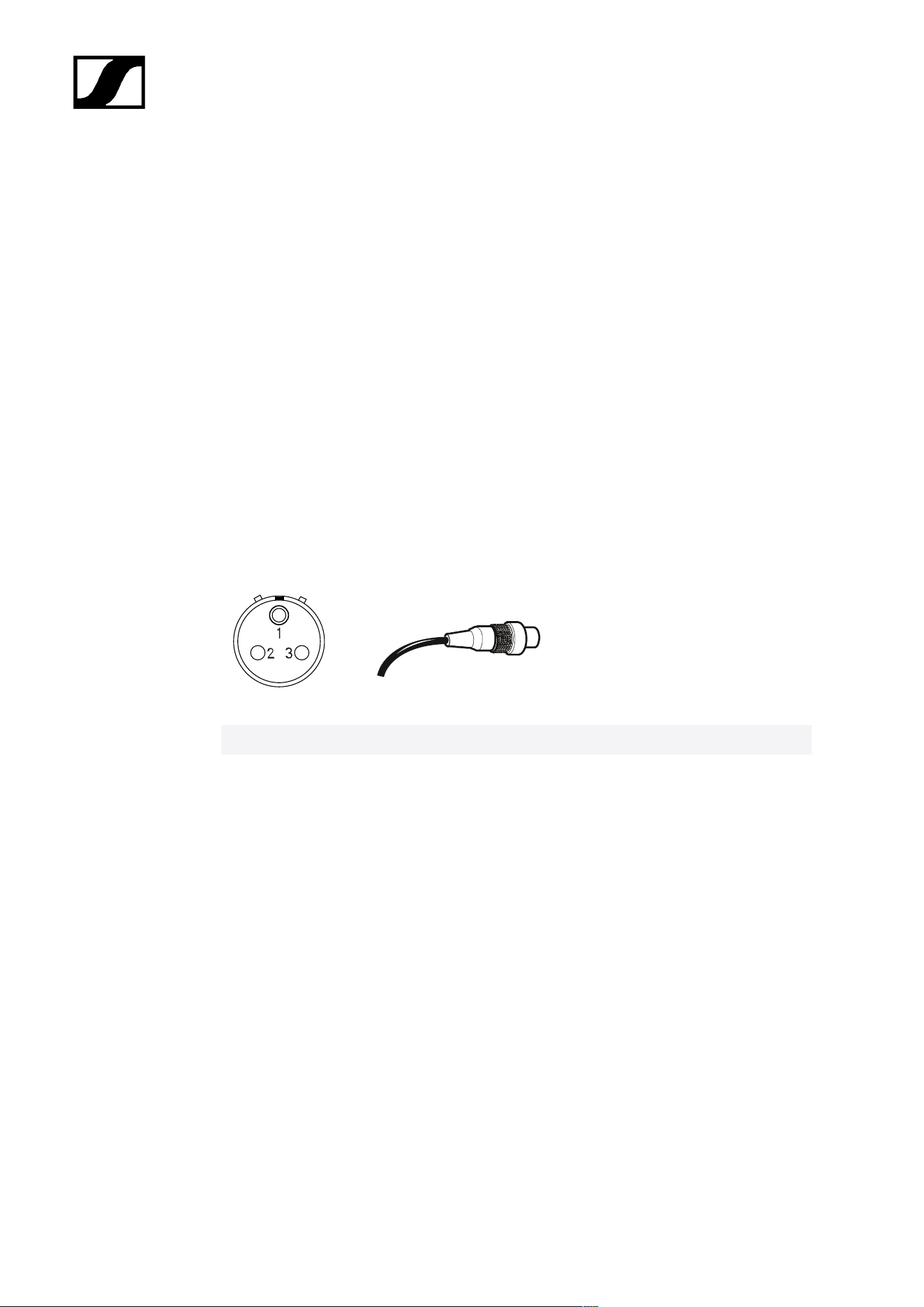
| 6 - Specifications
SEK
RF transmission power
• up to 50 mW; countrywise limited
RF channels
• 1
Headphone output
• 3.5 mm TRS jack
• 2× 300 mW RMS (32 Ω, -40 dB THD, 1 kHz)
Microphone / Instrument / Command input
• 3-pin audio socket
Solder side
Assignment Function
Pin 1 Ground & housing
Pin 2 Line In / command*
Pin 3 Mic In & bias voltage
Housing Ground
*for auto line detection short pin 1 and 3
Power supply
• BA 70 rechargeable battery pack
Battery operating time
• up to 7 h (unidirectional microphone use)
• up to 6 h (unidirectional IEM use)
• up to 5 h (bidirectional use)
Dimensions
• approx. 83 x 62 x 21 mm (3.39" x 2.44" x 0.83") (without antenna)
266

| 6 - Specifications
Weight
• approx. 178 g (0.39 lbs) (with BA 70)
• approx. 144 g (0.32 lbs) (without BA 70)
Temperature
• Operation: −10 °C to +50 °C (14 °F to 122 °F)
• Storage: −25 °C to +70 °C −13 °F to 158 °F)
Relative air humidity
• 25 % to 95 % (non-condensing)
267

| 6 - Specifications
SKM
RF transmission power
• up to 50 mW; countrywise limited
RF channels
• 1
Power supply
• BA 70 rechargeable battery pack
Battery operating time
• > 6 h in live mode
Dimensions
• length: 196 mm (7.72")
• diameter: 40 mm (1.57") (capsule interface), 33,3 mm (1.31") (shaft)
Weight
• approx. 196 g (0.43 lbs) (without BA 70, without module)
Temperature
• Operation: −10 °C to +50 °C (14 °F to 122 °F)
• Storage: −25 °C to +70 °C −13 °F to 158 °F)
Relative air humidity
• 25 % to 95 % (non-condensing)
268

| 6 - Specifications
SKM COM
Dimensions
• approx. ⌀40 x 23 mm (1.57" x 0.91")
Weight
• approx. 49 g (0.11 lbs)
Temperature
• Operation: −10 °C to +50 °C (14 °F to 122 °F)
• Storage: −25 °C to +70 °C −13 °F to 158 °F)
Relative air humidity
• 25 % to 95 % (non-condensing)
269

| 6 - Specifications
DAD
RF transmission power
• up to 100 mW; countrywise limited
RF channels
• 1
Base Station connection
• Ruggedized RJ45 including PoE, max. 100 m cable, CAT5e or better, 1 Gbit/s
Power consumption
• PoE class 2 (< 6.5 W)
Apex angle vertical
• vertical
• UHF: 65 °
• 1G4: 62 °
• horizontal
• UHF: 109 °
• 1G4: 93 °
Front to back ratio
• UHF: 15 dB
• 1G4: 17 dB
Gain
• UHF: 5 dB
• 1G4: 6.5 dB
Threads for tripod mounting
• Yes / Adapter 3/8" to 5/8"
Dimensions
• UHF: 349 x 292 x 39 mm (13.74" x 11.5" x 1.54")
• 1G4: 231 x 205 x 39 mm (9.09" x 8.07" x 1.54")
Weight
• UHF: 676 g (1.49 lbs)
• 1G4: 534 g (1.18 lbs)
270

| 6 - Specifications
Temperature
• Operation: −10 °C to +60 °C (14 °F to 140 °F)
• Storage: −25 °C to +80 °C −13 °F to 176 °F)
Relative air humidity
• 25 % to 95 % (non-condensing)
IP class
• IP54
271

| 6 - Specifications
CHG 70N-C charger
Power supply
• 12 V DC (single unit or cascade of up to 5 units)
• PoE IEEE 802.3af Class 0 (CAT5e or higher), single unit only
Current consumption
max. 3.5 A for a cascade of up to 5 units
Ethernet
• RJ-45 socket, IEEE802.3
• 100Base-TX (half+full duplex)
• 10Base-T (half+full duplex)
Dimensions
Approx. 200 x 104 x 116 mm
Weight
Approx. 640 g, without power supply unit
Charging slots
2
Charging capacity per slot
• BA 70 rechargeable battery or
• EW-DX SK with BA 70 or
• EW-DX SKM with BA 70 or
• SPECTERA SEK UHF/1G4
Charging voltage
4.35 V
Charging current
min. 344 mA
max. 860 mA
Full charging time
Max. 3.5 h
Temperature range
• Charging: -10 °C to +50 °C
• Storage: -20 °C to +70 °C
272

| 6 - Specifications
Relative humidity
Max. 95% (non-condensing)
273

| 6 - Specifications
BA 70 rechargeable battery
Rated capacity
1720 mAh
Nominal voltage
3.8 V
Charging voltage
max. 4.35 V
Charging time
Typically 3 h @ room temperature
Dimensions
Approx. 54 x 30 x 15
Weight
Approx. 33 g
Temperature range
• Charging: 0 °C – +55 °C (32 °F – 131 °F)
• Discharging: -10 °C to +55 °C
• Storage: -10 °C to +45 °C
Relative humidity
• Charging/discharging: 25% to 95%, non-condensing
• Storage: 30% to 70%, non-condensing
274

| 6 - Specifications
L 70 USB charger
Charging capacity
2 Sennheiser BA 70 rechargeable battery packs
2x Sennheiser battery BA 62 with 2x L 70 adapter BA 62
Input voltage
Typically 5 V
Input current
max. 2 A
Charging voltage
nominally 4.35 V
Charging current
max. 860 mA per battery pack
Charging time
max. 3.5 h with NT 5-20 UCW power supply unit
Temperature range
• Charging: 0 °C to +55 °C
• Storage: -20 °C to +70 °C
Relative humidity
Max. 95% (non-condensing)
Dimensions
100 × 35 × 70 mm (1 3/4" x 3 7/8" x 7 3/16")
Weight
Approx. 86 g
275

| 6 - Specifications
Modular L 6000 charger
Charging capacity
• Up to 8 rechargeable batteries (BA 60, BA 61, BA 62 and BA 70) across 4
exchangeable charging modules (LM 6060, LM 6061, LM 6062 and LM 6070)
Charging times at 20° C
• BA 60
• 80%: approx. 1:15 h (approx. 4:45 h operating time)
• Full: approx. 2:30 h
• BA 61
• 80%: approx. 1:45 h (approx. 5:00 h operating time)
• Full: approx. 3:15 h
• BA 62
• 80%: approx. 1:15 h (approx. 9:30 h operating time)
• Full: approx. 2:45 h
• BA 70
• 80%: approx. 1:45 h
• Full: approx. 3:30 h
Charging temperature range
• 0 to 50 °C (32 °F to 122 °F)
Charging status display
• Multi-colored
Network
• IEEE 802.3-2002 (10/100 Mbit/s), shielded RJ-45 connection
Power supply
• AC 100 – 240 V, 50/60 Hz
Maximum power consumption
• 85 W
Minimum power consumption
• 1 W
Power plug
• 3-pin, protection class I as per IEC/EN 60320-1
276

| 6 - Specifications
Dimensions (H x W x D with mounting elements)
• 44 x 483 x 373 mm (1.73" x 19.02" x 14.69")
Weight
• 5.1 kg (11.24 lbs)
277

| 6 - Specifications
LM 6060 | LM 6061 | LM 6062 | LM 6070 charging
modules
Dimensions (H x W x L)
• 44 x 99 x 182 mm (1.73" x 3.9" x 7.17")
Weight
• 144 g (0.32 lbs)
Rechargeable battery type
• LM 6060: 2x BA 60
• LM 6061: 2x BA 61
• LM 6062: 2x BA 62
• LM 6070: 2x BA 70
278

Sennheiser electronic SE & Co. KG | Am Labor 1 | 30900 Wedemark | Germany