Operation Manual
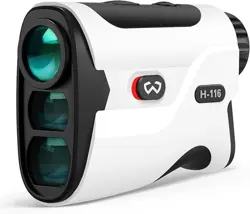
Golf Rangefinder
H-116 Operation Manual
1. Product Specifications
2. Instructions for Use
1.1 General Index
Range
Range Measuring Accuracy
Laser Type
Magnification
Exit Pupil Diameter
Object Lens Size
Field Angle
Battery
Weight
Dimensions
Operating Temperature
Rangefinder(1pcs)
5-1200(Y)
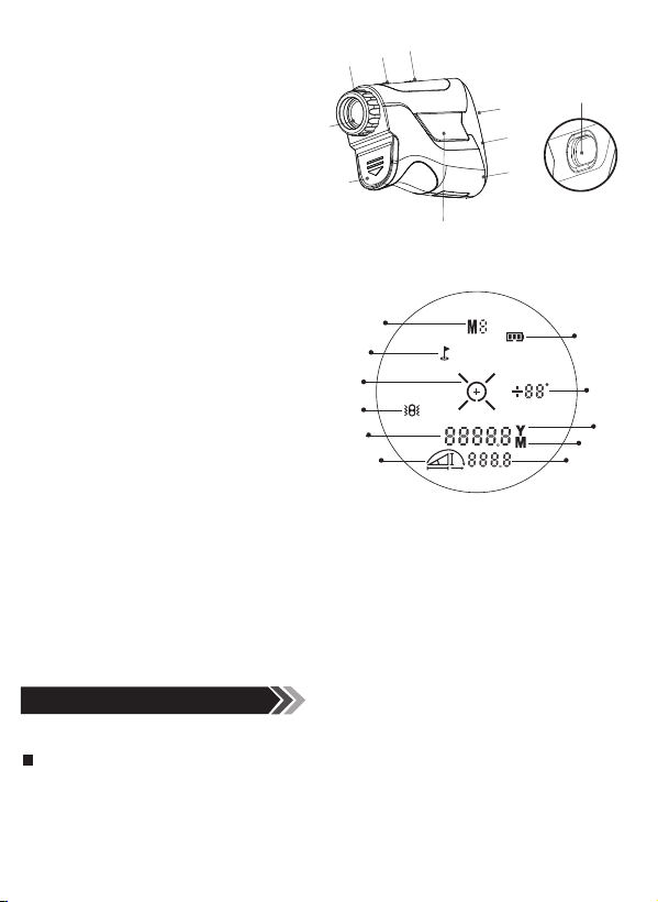
1) Objective Lens
2) Emitter Lens
3) Receiving Lens
4) Mode/Meter & Yard Select Button
5) Power Start Button
6) Focusing Ring
7) Eyepiece
8) Battery Cover
9) Magnetic Iron
10) Slope On/Off Switch
10
1
2
3
4
5
9
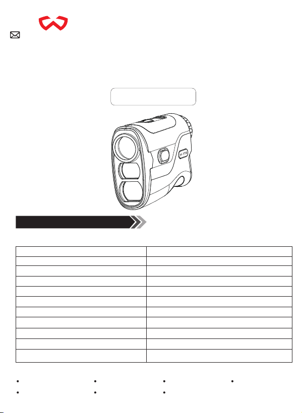
Figure 1
Parts of Device
Figure 2
LCD Display
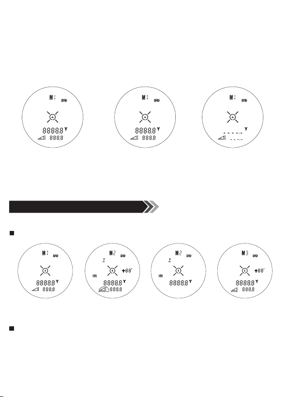
Figure 5
Single Measurement
Figure 6
Continuous Measurement
Figure 7
Failure Measurement
Figure 8
Range Mode
Figure 9
Slope Mode
Figure 10
Non-slope mode
Figure 11
Bow hunting mode
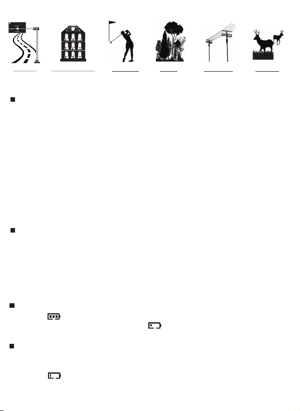
The range finder is suitable for measuring high reflectivity objects(such as highway's
signpad), moderate reflectivity objects(such as building's wall)and low reflectivity
objects(such as tree, golf flag, utility pole, animal etc.) When there flectance is reduced
to a certain extent, the range will be reduced accordingly.
1)Target reflectivity: Generally speaking, the higher the reflectivity of the object, the
better the ranging ability.(It may be fail to measure the target that can hardly create
diffuse reflection, such as water surface.)
2)Target shape: When a target is too small or uneven, ranging capability and range
corresponding speed will decrease.
3)Measuring angle: The ranging ability would be better if the measured object is
vertical with laser emission's direction. It's possible that the measuring range cannot
meet the ranging ability specified in the manual under some extreme conditions.
4)Environment factor: The environment factors including sunshine intensity, the
concentration of water vapor in the air and suspended particles.(such as rain fog,
snow, fog, haze, etc.)
1)The measurement target is with moderate reflectivity, such as building walls.
2)The measured object is vertical with laser emission direction.
3)The weather condition is sunny but not direct sunlight.
Full power:
±1Y
905nm(Class I)
6X
3.7mm
22mm
7.5°
CR2-3V
145g
103*77*34mm
-10°C-50°C
1
4 5 6
V1.0
2 3
1.2 List of Accessories
1.3 Parts of Device
Measurement Targets
Factors that Influence Ranging Capability
2.1 Measurement Considerations
2.2 Battery Instructions
1) Mode
2) Flag Lock
3) Target
4) Vibration
5) Range Data
6) Slope Distance Symbol
7) Battery Indicator
8) Angle
9) Yard
10) Meter
11) Vertical/Horizontal/Slope Compensation Distance
LCD screen uses the most advanced technology, but this does not ensure completely
removal of dust.When using this product, the LCD screen will be in high magnification
and dust may appear in the form of defects, but does not affect ranging function.
1.4 LCD Display Description
Note:
If the measure fails, the measured value on the screen will display as:"---”
Note:
3. General Operation
Power on: Press the power button for more than 2 seconds and all the signs will show
on the LCD screen. If only short press the power button, the LCD screen just displays
last used or default mode signs, but not all signs.
Power off: The product will shutdown automatically in 8 seconds if no any operations.
3.1 Power on/Power off
4. Model Operating Instructions
4.1 H-116
5. Safety Precautions
"M"or "Yard" Unit Setting: In the boot state, long press of the mode button to change
the unit of length, M or Yard.
Mode switching: In the boot state, press the mode button and keep less than 2
seconds, then measurement mode switch can be activated.
3.2 Unit/Mode Switching
Single measurement: Short press the power button to start single measurement. (as
figure 5)
Continuous measurement: Press the power button and keep over 2 seconds to start the
continuous measurement. (as figure 6)
Failure measurement: Failure Measurement shows like figure 7. The product will
shut down automatically in 8 seconds without any operations. Press the power button
again and it will start on.
3.4 Single Measurement / Continuous Measurement / Failure Measurement
The Range Ability of the Product Defined Under the Following Conditions:
Power Indication
Battery Service Life
Battery runs out and needs to be replaced:
Continuous operation times: About 5000 times (25
O
C). The times will change
somewhat due to the different conditions.
When icon " " flashes, the battery is low and should be replaced immediately
to avoid inaccuracy or non-working.
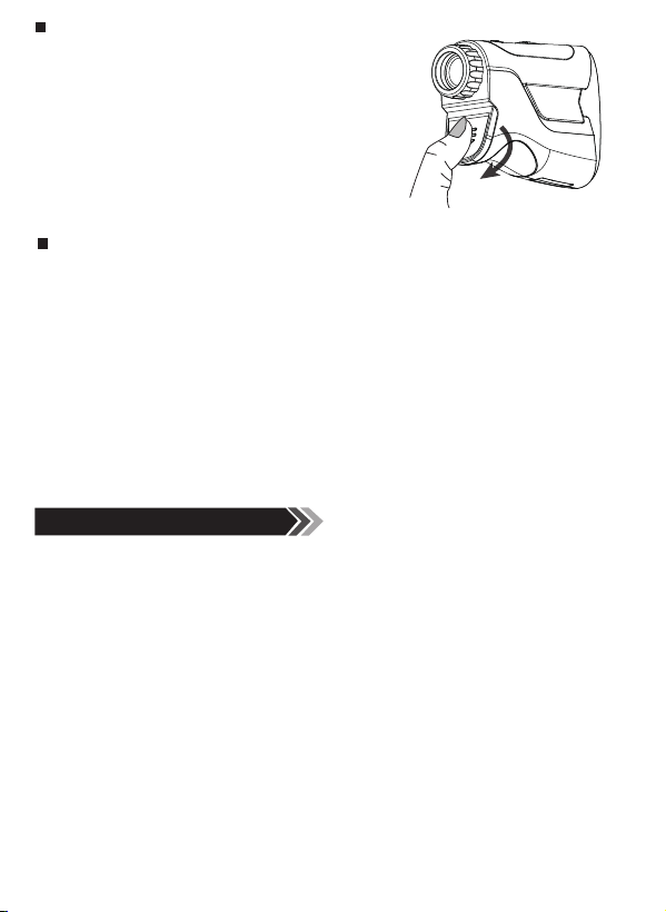
Replace the Battery
1) Press the battery cover firmly and slide it
downwards to open it. (as figure 4)
2) Be sure to insert each battery so its polarity
(+/-direction) matches the polarity indications are
inside the battery compartment, then close the
battery door is closed after loading the batteries.
Cautions
Mode Icon
Mode Description
1) Please tear off the plastic film before installing the battery.
2) Please take out the battery at once if it runs out or doesn't use for a long time.
3) The battery should be installed with the "+,-" poles in right direction according to
battery housing label indication.
4) Please use the same specification CR2 brand battery. Explosion or leakage of
liquid due to the use of sub-CR2 batteries, we will not assume any responsibility.
5) Please don't put the battery together with metal items such as keys, coins in one
pocket or it may cause overheating by short circuit of the battery.
6) Don't keep the battery in extreme temperature environments.
7) Waste battery disposal should comply with local laws and regulations.
1)M1 Mode: Short press the power button to measure straight-line distance and height.
(as figure 8)
2)M2 Mode: Slope mode, short press the power button to lock the flag, rangefinder will
vibrate when the target is locked. The angle and the distance with slope compensation
will display at the screen. (as figure 9)
3)M2 Mode: Non-slope mode, short press the power button to lock the flag, the
rangefinder will vibrate when the target is locked. Meanwhile, the straight-line
distance will displayonthescreen. (as figure 10)
4)M3 Mode: Bow hunting mode, short press the power button to switch to M3 mode,
which can measure straight-line distance, horizontal distance and angle. (as figure 11)
Carry Bag(1pcs) Lens Cloth(1pcs)
Lithium Battery(1pcs) Hang String(1pcs) User Manual(1pcs)
Carabiner(1pcs)
7
6
8
Figure 4
Battery Replacement Illustration
When the slope switch displays the red area, it means the slope compensation
function is turned off to comply with golf tournament regulations.
When the slope switch is on and the red area is covered, the slope is on for amateur
use and training.
3.3 Slope on/Slope off
1
7
8
9
10
11
2
3
4
5
6
Golf Flag
Building’s Wall
Trees Utility Pole Animals
SignPad
S
Figure 3 Measurement targets
5.1 Transport/Storage/Maintenance/Disposal
Transport: Please add enough cushioning material in the box to avoid damaging the
machine while in transport. When the machine falls on the ground, and makes a
strange noise, please remove the battery immediately and stop using.
Storage : Please keep the product out of reach of children. Don't put it on a high and
unsteady place to prevent falling on the ground. Do not place the product in a high
temperature environment or it may cause damage of the products.
Maintenance: If the product is used in rapidly changing temperature, The lens surface
will covered by fog. So please don't use it before the fog evaporates. Please clean with
lens cloth but not your hands when it is dirty, or it may cause damage to the glass
coating .
Disposal: The product package and discarded products should be recycled or
disposed properly in accordance with local laws.
This equipment has been tested and found to comply with the limits for a Class B
digital device, pursuant to Part 15 of the FCC Rules. These limits are designed to
provide reasonable protection against harmful interference in a residential installation.
This equipment generates, uses and can radiate radio frequency energy and if not
installed and used in accordance with the instructions, may cause harmful interference
to radio communications. However, there is no guarantee that interference will not
occur in a particular installation. If this equipment does cause harmful interference to
radio or television reception, which can be determined by turning the equipment off
and on, the user is encouraged to try to correct the interference by one or more of the
following measures:
• Reorient or relocate the receiving antenna.
• Increase the separation between the equipment and receiver.
• Connect the equipment into an outlet on a circuit different from that to which the
receiver is connected.
• Consult the dealer or an experienced radio/TV technician for help. Shielded interface
cable must be used with the equipment in order to comply with the limits for a digital
device pursuant to Subpart B of Part 15 of FCC Rules. Specifications and designs are
subject to change without any notice or obligation on the part of the manufacturer.
Operation Manual
Golf Rangefinder
H-116 Operation Manual
1. Product Specifications
2. Instructions for Use
1.1 General Index
Range
Range Measuring Accuracy
Laser Type
Magnification
Exit Pupil Diameter
Object Lens Size
Field Angle
Battery
Weight
Dimensions
Operating Temperature
Rangefinder(1pcs)
5-1200(Y)
1) Objective Lens
2) Emitter Lens
3) Receiving Lens
4) Mode/Meter & Yard Select Button
5) Power Start Button
6) Focusing Ring
7) Eyepiece
8) Battery Cover
9) Magnetic Iron
10) Slope On/Off Switch
10
1
2
3
4
5
9
Figure 1
Parts of Device
Figure 2
LCD Display
Figure 5
Single Measurement
Figure 6
Continuous Measurement
Figure 7
Failure Measurement
Figure 8
Range Mode
Figure 9
Slope Mode
Figure 10
Non-slope mode
Figure 11
Bow hunting mode
The range finder is suitable for measuring high reflectivity objects(such as highway's
signpad), moderate reflectivity objects(such as building's wall)and low reflectivity
objects(such as tree, golf flag, utility pole, animal etc.) When there flectance is reduced
to a certain extent, the range will be reduced accordingly.
1)Target reflectivity: Generally speaking, the higher the reflectivity of the object, the
better the ranging ability.(It may be fail to measure the target that can hardly create
diffuse reflection, such as water surface.)
2)Target shape: When a target is too small or uneven, ranging capability and range
corresponding speed will decrease.
3)Measuring angle: The ranging ability would be better if the measured object is
vertical with laser emission's direction. It's possible that the measuring range cannot
meet the ranging ability specified in the manual under some extreme conditions.
4)Environment factor: The environment factors including sunshine intensity, the
concentration of water vapor in the air and suspended particles.(such as rain fog,
snow, fog, haze, etc.)
1)The measurement target is with moderate reflectivity, such as building walls.
2)The measured object is vertical with laser emission direction.
3)The weather condition is sunny but not direct sunlight.
Full power:
±1Y
905nm(Class I)
6X
3.7mm
22mm
7.5°
CR2-3V
145g
103*77*34mm
-10°C-50°C
1
4 5 6
V1.0
2 3
1.2 List of Accessories
1.3 Parts of Device
Measurement Targets
Factors that Influence Ranging Capability
2.1 Measurement Considerations
2.2 Battery Instructions
1) Mode
2) Flag Lock
3) Target
4) Vibration
5) Range Data
6) Slope Distance Symbol
7) Battery Indicator
8) Angle
9) Yard
10) Meter
11) Vertical/Horizontal/Slope Compensation Distance
LCD screen uses the most advanced technology, but this does not ensure completely
removal of dust.When using this product, the LCD screen will be in high magnification
and dust may appear in the form of defects, but does not affect ranging function.
1.4 LCD Display Description
Note:
If the measure fails, the measured value on the screen will display as:"---”
Note:
3. General Operation
Power on: Press the power button for more than 2 seconds and all the signs will show
on the LCD screen. If only short press the power button, the LCD screen just displays
last used or default mode signs, but not all signs.
Power off: The product will shutdown automatically in 8 seconds if no any operations.
3.1 Power on/Power off
4. Model Operating Instructions
4.1 H-116
5. Safety Precautions
"M"or "Yard" Unit Setting: In the boot state, long press of the mode button to change
the unit of length, M or Yard.
Mode switching: In the boot state, press the mode button and keep less than 2
seconds, then measurement mode switch can be activated.
3.2 Unit/Mode Switching
Single measurement: Short press the power button to start single measurement. (as
figure 5)
Continuous measurement: Press the power button and keep over 2 seconds to start the
continuous measurement. (as figure 6)
Failure measurement: Failure Measurement shows like figure 7. The product will
shut down automatically in 8 seconds without any operations. Press the power button
again and it will start on.
3.4 Single Measurement / Continuous Measurement / Failure Measurement
The Range Ability of the Product Defined Under the Following Conditions:
Power Indication
Battery Service Life
Battery runs out and needs to be replaced:
Continuous operation times: About 5000 times (25
O
C). The times will change
somewhat due to the different conditions.
When icon " " flashes, the battery is low and should be replaced immediately
to avoid inaccuracy or non-working.
Replace the Battery
1) Press the battery cover firmly and slide it
downwards to open it. (as figure 4)
2) Be sure to insert each battery so its polarity
(+/-direction) matches the polarity indications are
inside the battery compartment, then close the
battery door is closed after loading the batteries.
Cautions
Mode Icon
Mode Description
1) Please tear off the plastic film before installing the battery.
2) Please take out the battery at once if it runs out or doesn't use for a long time.
3) The battery should be installed with the "+,-" poles in right direction according to
battery housing label indication.
4) Please use the same specification CR2 brand battery. Explosion or leakage of
liquid due to the use of sub-CR2 batteries, we will not assume any responsibility.
5) Please don't put the battery together with metal items such as keys, coins in one
pocket or it may cause overheating by short circuit of the battery.
6) Don't keep the battery in extreme temperature environments.
7) Waste battery disposal should comply with local laws and regulations.
1)M1 Mode: Short press the power button to measure straight-line distance and height.
(as figure 8)
2)M2 Mode: Slope mode, short press the power button to lock the flag, rangefinder will
vibrate when the target is locked. The angle and the distance with slope compensation
will display at the screen. (as figure 9)
3)M2 Mode: Non-slope mode, short press the power button to lock the flag, the
rangefinder will vibrate when the target is locked. Meanwhile, the straight-line
distance will displayonthescreen. (as figure 10)
4)M3 Mode: Bow hunting mode, short press the power button to switch to M3 mode,
which can measure straight-line distance, horizontal distance and angle. (as figure 11)
Carry Bag(1pcs) Lens Cloth(1pcs)
Lithium Battery(1pcs) Hang String(1pcs) User Manual(1pcs)
Carabiner(1pcs)
7
6
8
Figure 4
Battery Replacement Illustration
services@wogree.com
When the slope switch displays the red area, it means the slope compensation
function is turned off to comply with golf tournament regulations.
When the slope switch is on and the red area is covered, the slope is on for amateur
use and training.
3.3 Slope on/Slope off
1
7
8
9
10
11
2
3
4
5
6
Golf Flag
Building’s Wall
Trees Utility Pole Animals
SignPad
S
Figure 3 Measurement targets
5.1 Transport/Storage/Maintenance/Disposal
Transport: Please add enough cushioning material in the box to avoid damaging the
machine while in transport. When the machine falls on the ground, and makes a
strange noise, please remove the battery immediately and stop using.
Storage : Please keep the product out of reach of children. Don't put it on a high and
unsteady place to prevent falling on the ground. Do not place the product in a high
temperature environment or it may cause damage of the products.
Maintenance: If the product is used in rapidly changing temperature, The lens surface
will covered by fog. So please don't use it before the fog evaporates. Please clean with
lens cloth but not your hands when it is dirty, or it may cause damage to the glass
coating .
Disposal: The product package and discarded products should be recycled or
disposed properly in accordance with local laws.
This equipment has been tested and found to comply with the limits for a Class B
digital device, pursuant to Part 15 of the FCC Rules. These limits are designed to
provide reasonable protection against harmful interference in a residential installation.
This equipment generates, uses and can radiate radio frequency energy and if not
installed and used in accordance with the instructions, may cause harmful interference
to radio communications. However, there is no guarantee that interference will not
occur in a particular installation. If this equipment does cause harmful interference to
radio or television reception, which can be determined by turning the equipment off
and on, the user is encouraged to try to correct the interference by one or more of the
following measures:
• Reorient or relocate the receiving antenna.
• Increase the separation between the equipment and receiver.
• Connect the equipment into an outlet on a circuit different from that to which the
receiver is connected.
• Consult the dealer or an experienced radio/TV technician for help. Shielded interface
cable must be used with the equipment in order to comply with the limits for a digital
device pursuant to Subpart B of Part 15 of FCC Rules. Specifications and designs are
subject to change without any notice or obligation on the part of the manufacturer.
Operation Manual
Golf Rangefinder
H-116 Operation Manual
1. Product Specifications
2. Instructions for Use
1.1 General Index
Range
Range Measuring Accuracy
Laser Type
Magnification
Exit Pupil Diameter
Object Lens Size
Field Angle
Battery
Weight
Dimensions
Operating Temperature
Rangefinder(1pcs)
5-1200(Y)
1) Objective Lens
2) Emitter Lens
3) Receiving Lens
4) Mode/Meter & Yard Select Button
5) Power Start Button
6) Focusing Ring
7) Eyepiece
8) Battery Cover
9) Magnetic Iron
10) Slope On/Off Switch
10
1
2
3
4
5
9
Figure 1
Parts of Device
Figure 2
LCD Display
Figure 5
Single Measurement
Figure 6
Continuous Measurement
Figure 7
Failure Measurement
Figure 8
Range Mode
Figure 9
Slope Mode
Figure 10
Non-slope mode
Figure 11
Bow hunting mode
The range finder is suitable for measuring high reflectivity objects(such as highway's
signpad), moderate reflectivity objects(such as building's wall)and low reflectivity
objects(such as tree, golf flag, utility pole, animal etc.) When there flectance is reduced
to a certain extent, the range will be reduced accordingly.
1)Target reflectivity: Generally speaking, the higher the reflectivity of the object, the
better the ranging ability.(It may be fail to measure the target that can hardly create
diffuse reflection, such as water surface.)
2)Target shape: When a target is too small or uneven, ranging capability and range
corresponding speed will decrease.
3)Measuring angle: The ranging ability would be better if the measured object is
vertical with laser emission's direction. It's possible that the measuring range cannot
meet the ranging ability specified in the manual under some extreme conditions.
4)Environment factor: The environment factors including sunshine intensity, the
concentration of water vapor in the air and suspended particles.(such as rain fog,
snow, fog, haze, etc.)
1)The measurement target is with moderate reflectivity, such as building walls.
2)The measured object is vertical with laser emission direction.
3)The weather condition is sunny but not direct sunlight.
Full power:
±1Y
905nm(Class I)
6X
3.7mm
22mm
7.5°
CR2-3V
145g
103*77*34mm
-10°C-50°C
1
4 5 6
V1.0
2 3
1.2 List of Accessories
1.3 Parts of Device
Measurement Targets
Factors that Influence Ranging Capability
2.1 Measurement Considerations
2.2 Battery Instructions
1) Mode
2) Flag Lock
3) Target
4) Vibration
5) Range Data
6) Slope Distance Symbol
7) Battery Indicator
8) Angle
9) Yard
10) Meter
11) Vertical/Horizontal/Slope Compensation Distance
LCD screen uses the most advanced technology, but this does not ensure completely
removal of dust.When using this product, the LCD screen will be in high magnification
and dust may appear in the form of defects, but does not affect ranging function.
1.4 LCD Display Description
Note:
If the measure fails, the measured value on the screen will display as:"---”
Note:
3. General Operation
Power on: Press the power button for more than 2 seconds and all the signs will show
on the LCD screen. If only short press the power button, the LCD screen just displays
last used or default mode signs, but not all signs.
Power off: The product will shutdown automatically in 8 seconds if no any operations.
3.1 Power on/Power off
4. Model Operating Instructions
4.1 H-116
5. Safety Precautions
"M"or "Yard" Unit Setting: In the boot state, long press of the mode button to change
the unit of length, M or Yard.
Mode switching: In the boot state, press the mode button and keep less than 2
seconds, then measurement mode switch can be activated.
3.2 Unit/Mode Switching
Single measurement: Short press the power button to start single measurement. (as
figure 5)
Continuous measurement: Press the power button and keep over 2 seconds to start the
continuous measurement. (as figure 6)
Failure measurement: Failure Measurement shows like figure 7. The product will
shut down automatically in 8 seconds without any operations. Press the power button
again and it will start on.
3.4 Single Measurement / Continuous Measurement / Failure Measurement
The Range Ability of the Product Defined Under the Following Conditions:
Power Indication
Battery Service Life
Battery runs out and needs to be replaced:
Continuous operation times: About 5000 times (25
O
C). The times will change
somewhat due to the different conditions.
When icon " " flashes, the battery is low and should be replaced immediately
to avoid inaccuracy or non-working.
Replace the Battery
1) Press the battery cover firmly and slide it
downwards to open it. (as figure 4)
2) Be sure to insert each battery so its polarity
(+/-direction) matches the polarity indications are
inside the battery compartment, then close the
battery door is closed after loading the batteries.
Cautions
Mode Icon
Mode Description
1) Please tear off the plastic film before installing the battery.
2) Please take out the battery at once if it runs out or doesn't use for a long time.
3) The battery should be installed with the "+,-" poles in right direction according to
battery housing label indication.
4) Please use the same specification CR2 brand battery. Explosion or leakage of
liquid due to the use of sub-CR2 batteries, we will not assume any responsibility.
5) Please don't put the battery together with metal items such as keys, coins in one
pocket or it may cause overheating by short circuit of the battery.
6) Don't keep the battery in extreme temperature environments.
7) Waste battery disposal should comply with local laws and regulations.
1)M1 Mode: Short press the power button to measure straight-line distance and height.
(as figure 8)
2)M2 Mode: Slope mode, short press the power button to lock the flag, rangefinder will
vibrate when the target is locked. The angle and the distance with slope compensation
will display at the screen. (as figure 9)
3)M2 Mode: Non-slope mode, short press the power button to lock the flag, the
rangefinder will vibrate when the target is locked. Meanwhile, the straight-line
distance will displayonthescreen. (as figure 10)
4)M3 Mode: Bow hunting mode, short press the power button to switch to M3 mode,
which can measure straight-line distance, horizontal distance and angle. (as figure 11)
Carry Bag(1pcs) Lens Cloth(1pcs)
Lithium Battery(1pcs) Hang String(1pcs) User Manual(1pcs)
Carabiner(1pcs)
7
6
8
Figure 4
Battery Replacement Illustration
services@wogree.com
When the slope switch displays the red area, it means the slope compensation
function is turned off to comply with golf tournament regulations.
When the slope switch is on and the red area is covered, the slope is on for amateur
use and training.
3.3 Slope on/Slope off
1
7
8
9
10
11
2
3
4
5
6
Golf Flag
Building’s Wall
Trees Utility Pole Animals
SignPad
S
Figure 3 Measurement targets
5.1 Transport/Storage/Maintenance/Disposal
Transport: Please add enough cushioning material in the box to avoid damaging the
machine while in transport. When the machine falls on the ground, and makes a
strange noise, please remove the battery immediately and stop using.
Storage : Please keep the product out of reach of children. Don't put it on a high and
unsteady place to prevent falling on the ground. Do not place the product in a high
temperature environment or it may cause damage of the products.
Maintenance: If the product is used in rapidly changing temperature, The lens surface
will covered by fog. So please don't use it before the fog evaporates. Please clean with
lens cloth but not your hands when it is dirty, or it may cause damage to the glass
coating .
Disposal: The product package and discarded products should be recycled or
disposed properly in accordance with local laws.
This equipment has been tested and found to comply with the limits for a Class B
digital device, pursuant to Part 15 of the FCC Rules. These limits are designed to
provide reasonable protection against harmful interference in a residential installation.
This equipment generates, uses and can radiate radio frequency energy and if not
installed and used in accordance with the instructions, may cause harmful interference
to radio communications. However, there is no guarantee that interference will not
occur in a particular installation. If this equipment does cause harmful interference to
radio or television reception, which can be determined by turning the equipment off
and on, the user is encouraged to try to correct the interference by one or more of the
following measures:
• Reorient or relocate the receiving antenna.
• Increase the separation between the equipment and receiver.
• Connect the equipment into an outlet on a circuit different from that to which the
receiver is connected.
• Consult the dealer or an experienced radio/TV technician for help. Shielded interface
cable must be used with the equipment in order to comply with the limits for a digital
device pursuant to Subpart B of Part 15 of FCC Rules. Specifications and designs are
subject to change without any notice or obligation on the part of the manufacturer.
Operation Manual
Golf Rangefinder
H-116 Operation Manual
1. Product Specifications
2. Instructions for Use
1.1 General Index
Range
Range Measuring Accuracy
Laser Type
Magnification
Exit Pupil Diameter
Object Lens Size
Field Angle
Battery
Weight
Dimensions
Operating Temperature
Rangefinder(1pcs)
5-1200(Y)
1) Objective Lens
2) Emitter Lens
3) Receiving Lens
4) Mode/Meter & Yard Select Button
5) Power Start Button
6) Focusing Ring
7) Eyepiece
8) Battery Cover
9) Magnetic Iron
10) Slope On/Off Switch
10
1
2
3
4
5
9
Figure 1
Parts of Device
Figure 2
LCD Display
Figure 5
Single Measurement
Figure 6
Continuous Measurement
Figure 7
Failure Measurement
Figure 8
Range Mode
Figure 9
Slope Mode
Figure 10
Non-slope mode
Figure 11
Bow hunting mode
The range finder is suitable for measuring high reflectivity objects(such as highway's
signpad), moderate reflectivity objects(such as building's wall)and low reflectivity
objects(such as tree, golf flag, utility pole, animal etc.) When there flectance is reduced
to a certain extent, the range will be reduced accordingly.
1)Target reflectivity: Generally speaking, the higher the reflectivity of the object, the
better the ranging ability.(It may be fail to measure the target that can hardly create
diffuse reflection, such as water surface.)
2)Target shape: When a target is too small or uneven, ranging capability and range
corresponding speed will decrease.
3)Measuring angle: The ranging ability would be better if the measured object is
vertical with laser emission's direction. It's possible that the measuring range cannot
meet the ranging ability specified in the manual under some extreme conditions.
4)Environment factor: The environment factors including sunshine intensity, the
concentration of water vapor in the air and suspended particles.(such as rain fog,
snow, fog, haze, etc.)
1)The measurement target is with moderate reflectivity, such as building walls.
2)The measured object is vertical with laser emission direction.
3)The weather condition is sunny but not direct sunlight.
Full power:
±1Y
905nm(Class I)
6X
3.7mm
22mm
7.5°
CR2-3V
145g
103*77*34mm
-10°C-50°C
1
4 5 6
V1.0
2 3
1.2 List of Accessories
1.3 Parts of Device
Measurement Targets
Factors that Influence Ranging Capability
2.1 Measurement Considerations
2.2 Battery Instructions
1) Mode
2) Flag Lock
3) Target
4) Vibration
5) Range Data
6) Slope Distance Symbol
7) Battery Indicator
8) Angle
9) Yard
10) Meter
11) Vertical/Horizontal/Slope Compensation Distance
LCD screen uses the most advanced technology, but this does not ensure completely
removal of dust.When using this product, the LCD screen will be in high magnification
and dust may appear in the form of defects, but does not affect ranging function.
1.4 LCD Display Description
Note:
If the measure fails, the measured value on the screen will display as:"---”
Note:
3. General Operation
Power on: Press the power button for more than 2 seconds and all the signs will show
on the LCD screen. If only short press the power button, the LCD screen just displays
last used or default mode signs, but not all signs.
Power off: The product will shutdown automatically in 8 seconds if no any operations.
3.1 Power on/Power off
4. Model Operating Instructions
4.1 H-116
5. Safety Precautions
"M"or "Yard" Unit Setting: In the boot state, long press of the mode button to change
the unit of length, M or Yard.
Mode switching: In the boot state, press the mode button and keep less than 2
seconds, then measurement mode switch can be activated.
3.2 Unit/Mode Switching
Single measurement: Short press the power button to start single measurement. (as
figure 5)
Continuous measurement: Press the power button and keep over 2 seconds to start the
continuous measurement. (as figure 6)
Failure measurement: Failure Measurement shows like figure 7. The product will
shut down automatically in 8 seconds without any operations. Press the power button
again and it will start on.
3.4 Single Measurement / Continuous Measurement / Failure Measurement
The Range Ability of the Product Defined Under the Following Conditions:
Power Indication
Battery Service Life
Battery runs out and needs to be replaced:
Continuous operation times: About 5000 times (25
O
C). The times will change
somewhat due to the different conditions.
When icon " " flashes, the battery is low and should be replaced immediately
to avoid inaccuracy or non-working.
Replace the Battery
1) Press the battery cover firmly and slide it
downwards to open it. (as figure 4)
2) Be sure to insert each battery so its polarity
(+/-direction) matches the polarity indications are
inside the battery compartment, then close the
battery door is closed after loading the batteries.
Cautions
Mode Icon
Mode Description
1) Please tear off the plastic film before installing the battery.
2) Please take out the battery at once if it runs out or doesn't use for a long time.
3) The battery should be installed with the "+,-" poles in right direction according to
battery housing label indication.
4) Please use the same specification CR2 brand battery. Explosion or leakage of
liquid due to the use of sub-CR2 batteries, we will not assume any responsibility.
5) Please don't put the battery together with metal items such as keys, coins in one
pocket or it may cause overheating by short circuit of the battery.
6) Don't keep the battery in extreme temperature environments.
7) Waste battery disposal should comply with local laws and regulations.
1)M1 Mode: Short press the power button to measure straight-line distance and height.
(as figure 8)
2)M2 Mode: Slope mode, short press the power button to lock the flag, rangefinder will
vibrate when the target is locked. The angle and the distance with slope compensation
will display at the screen. (as figure 9)
3)M2 Mode: Non-slope mode, short press the power button to lock the flag, the
rangefinder will vibrate when the target is locked. Meanwhile, the straight-line
distance will displayonthescreen. (as figure 10)
4)M3 Mode: Bow hunting mode, short press the power button to switch to M3 mode,
which can measure straight-line distance, horizontal distance and angle. (as figure 11)
Carry Bag(1pcs) Lens Cloth(1pcs)
Lithium Battery(1pcs) Hang String(1pcs) User Manual(1pcs)
Carabiner(1pcs)
7
6
8
Figure 4
Battery Replacement Illustration
services@wogree.com
When the slope switch displays the red area, it means the slope compensation
function is turned off to comply with golf tournament regulations.
When the slope switch is on and the red area is covered, the slope is on for amateur
use and training.
3.3 Slope on/Slope off
1
7
8
9
10
11
2
3
4
5
6
Golf Flag
Building’s Wall
Trees Utility Pole Animals
SignPad
S
Figure 3 Measurement targets
5.1 Transport/Storage/Maintenance/Disposal
Transport: Please add enough cushioning material in the box to avoid damaging the
machine while in transport. When the machine falls on the ground, and makes a
strange noise, please remove the battery immediately and stop using.
Storage : Please keep the product out of reach of children. Don't put it on a high and
unsteady place to prevent falling on the ground. Do not place the product in a high
temperature environment or it may cause damage of the products.
Maintenance: If the product is used in rapidly changing temperature, The lens surface
will covered by fog. So please don't use it before the fog evaporates. Please clean with
lens cloth but not your hands when it is dirty, or it may cause damage to the glass
coating .
Disposal: The product package and discarded products should be recycled or
disposed properly in accordance with local laws.
This equipment has been tested and found to comply with the limits for a Class B
digital device, pursuant to Part 15 of the FCC Rules. These limits are designed to
provide reasonable protection against harmful interference in a residential installation.
This equipment generates, uses and can radiate radio frequency energy and if not
installed and used in accordance with the instructions, may cause harmful interference
to radio communications. However, there is no guarantee that interference will not
occur in a particular installation. If this equipment does cause harmful interference to
radio or television reception, which can be determined by turning the equipment off
and on, the user is encouraged to try to correct the interference by one or more of the
following measures:
• Reorient or relocate the receiving antenna.
• Increase the separation between the equipment and receiver.
• Connect the equipment into an outlet on a circuit different from that to which the
receiver is connected.
• Consult the dealer or an experienced radio/TV technician for help. Shielded interface
cable must be used with the equipment in order to comply with the limits for a digital
device pursuant to Subpart B of Part 15 of FCC Rules. Specifications and designs are
subject to change without any notice or obligation on the part of the manufacturer.
Operation Manual
Golf Rangefinder
H-116 Operation Manual
1. Product Specifications
2. Instructions for Use
1.1 General Index
Range
Range Measuring Accuracy
Laser Type
Magnification
Exit Pupil Diameter
Object Lens Size
Field Angle
Battery
Weight
Dimensions
Operating Temperature
Rangefinder(1pcs)
5-1200(Y)
1) Objective Lens
2) Emitter Lens
3) Receiving Lens
4) Mode/Meter & Yard Select Button
5) Power Start Button
6) Focusing Ring
7) Eyepiece
8) Battery Cover
9) Magnetic Iron
10) Slope On/Off Switch
10
1
2
3
4
5
9
Figure 1
Parts of Device
Figure 2
LCD Display
Figure 5
Single Measurement
Figure 6
Continuous Measurement
Figure 7
Failure Measurement
Figure 8
Range Mode
Figure 9
Slope Mode
Figure 10
Non-slope mode
Figure 11
Bow hunting mode
The range finder is suitable for measuring high reflectivity objects(such as highway's
signpad), moderate reflectivity objects(such as building's wall)and low reflectivity
objects(such as tree, golf flag, utility pole, animal etc.) When there flectance is reduced
to a certain extent, the range will be reduced accordingly.
1)Target reflectivity: Generally speaking, the higher the reflectivity of the object, the
better the ranging ability.(It may be fail to measure the target that can hardly create
diffuse reflection, such as water surface.)
2)Target shape: When a target is too small or uneven, ranging capability and range
corresponding speed will decrease.
3)Measuring angle: The ranging ability would be better if the measured object is
vertical with laser emission's direction. It's possible that the measuring range cannot
meet the ranging ability specified in the manual under some extreme conditions.
4)Environment factor: The environment factors including sunshine intensity, the
concentration of water vapor in the air and suspended particles.(such as rain fog,
snow, fog, haze, etc.)
1)The measurement target is with moderate reflectivity, such as building walls.
2)The measured object is vertical with laser emission direction.
3)The weather condition is sunny but not direct sunlight.
Full power:
±1Y
905nm(Class I)
6X
3.7mm
22mm
7.5°
CR2-3V
145g
103*77*34mm
-10°C-50°C
1
4 5 6
V1.0
2 3
1.2 List of Accessories
1.3 Parts of Device
Measurement Targets
Factors that Influence Ranging Capability
2.1 Measurement Considerations
2.2 Battery Instructions
1) Mode
2) Flag Lock
3) Target
4) Vibration
5) Range Data
6) Slope Distance Symbol
7) Battery Indicator
8) Angle
9) Yard
10) Meter
11) Vertical/Horizontal/Slope Compensation Distance
LCD screen uses the most advanced technology, but this does not ensure completely
removal of dust.When using this product, the LCD screen will be in high magnification
and dust may appear in the form of defects, but does not affect ranging function.
1.4 LCD Display Description
Note:
If the measure fails, the measured value on the screen will display as:"---”
Note:
3. General Operation
Power on: Press the power button for more than 2 seconds and all the signs will show
on the LCD screen. If only short press the power button, the LCD screen just displays
last used or default mode signs, but not all signs.
Power off: The product will shutdown automatically in 8 seconds if no any operations.
3.1 Power on/Power off
4. Model Operating Instructions
4.1 H-116
5. Safety Precautions
"M"or "Yard" Unit Setting: In the boot state, long press of the mode button to change
the unit of length, M or Yard.
Mode switching: In the boot state, press the mode button and keep less than 2
seconds, then measurement mode switch can be activated.
3.2 Unit/Mode Switching
Single measurement: Short press the power button to start single measurement. (as
figure 5)
Continuous measurement: Press the power button and keep over 2 seconds to start the
continuous measurement. (as figure 6)
Failure measurement: Failure Measurement shows like figure 7. The product will
shut down automatically in 8 seconds without any operations. Press the power button
again and it will start on.
3.4 Single Measurement / Continuous Measurement / Failure Measurement
The Range Ability of the Product Defined Under the Following Conditions:
Power Indication
Battery Service Life
Battery runs out and needs to be replaced:
Continuous operation times: About 5000 times (25
O
C). The times will change
somewhat due to the different conditions.
When icon " " flashes, the battery is low and should be replaced immediately
to avoid inaccuracy or non-working.
Replace the Battery
1) Press the battery cover firmly and slide it
downwards to open it. (as figure 4)
2) Be sure to insert each battery so its polarity
(+/-direction) matches the polarity indications are
inside the battery compartment, then close the
battery door is closed after loading the batteries.
Cautions
Mode Icon
Mode Description
1) Please tear off the plastic film before installing the battery.
2) Please take out the battery at once if it runs out or doesn't use for a long time.
3) The battery should be installed with the "+,-" poles in right direction according to
battery housing label indication.
4) Please use the same specification CR2 brand battery. Explosion or leakage of
liquid due to the use of sub-CR2 batteries, we will not assume any responsibility.
5) Please don't put the battery together with metal items such as keys, coins in one
pocket or it may cause overheating by short circuit of the battery.
6) Don't keep the battery in extreme temperature environments.
7) Waste battery disposal should comply with local laws and regulations.
1)M1 Mode: Short press the power button to measure straight-line distance and height.
(as figure 8)
2)M2 Mode: Slope mode, short press the power button to lock the flag, rangefinder will
vibrate when the target is locked. The angle and the distance with slope compensation
will display at the screen. (as figure 9)
3)M2 Mode: Non-slope mode, short press the power button to lock the flag, the
rangefinder will vibrate when the target is locked. Meanwhile, the straight-line
distance will displayonthescreen. (as figure 10)
4)M3 Mode: Bow hunting mode, short press the power button to switch to M3 mode,
which can measure straight-line distance, horizontal distance and angle. (as figure 11)
Carry Bag(1pcs) Lens Cloth(1pcs)
Lithium Battery(1pcs) Hang String(1pcs) User Manual(1pcs)
Carabiner(1pcs)
7
6
8
Figure 4
Battery Replacement Illustration
services@wogree.com
When the slope switch displays the red area, it means the slope compensation
function is turned off to comply with golf tournament regulations.
When the slope switch is on and the red area is covered, the slope is on for amateur
use and training.
3.3 Slope on/Slope off
1
7
8
9
10
11
2
3
4
5
6
Golf Flag
Building’s Wall
Trees Utility Pole Animals
SignPad
S
Figure 3 Measurement targets
5.1 Transport/Storage/Maintenance/Disposal
Transport: Please add enough cushioning material in the box to avoid damaging the
machine while in transport. When the machine falls on the ground, and makes a
strange noise, please remove the battery immediately and stop using.
Storage : Please keep the product out of reach of children. Don't put it on a high and
unsteady place to prevent falling on the ground. Do not place the product in a high
temperature environment or it may cause damage of the products.
Maintenance: If the product is used in rapidly changing temperature, The lens surface
will covered by fog. So please don't use it before the fog evaporates. Please clean with
lens cloth but not your hands when it is dirty, or it may cause damage to the glass
coating .
Disposal: The product package and discarded products should be recycled or
disposed properly in accordance with local laws.
This equipment has been tested and found to comply with the limits for a Class B
digital device, pursuant to Part 15 of the FCC Rules. These limits are designed to
provide reasonable protection against harmful interference in a residential installation.
This equipment generates, uses and can radiate radio frequency energy and if not
installed and used in accordance with the instructions, may cause harmful interference
to radio communications. However, there is no guarantee that interference will not
occur in a particular installation. If this equipment does cause harmful interference to
radio or television reception, which can be determined by turning the equipment off
and on, the user is encouraged to try to correct the interference by one or more of the
following measures:
• Reorient or relocate the receiving antenna.
• Increase the separation between the equipment and receiver.
• Connect the equipment into an outlet on a circuit different from that to which the
receiver is connected.
• Consult the dealer or an experienced radio/TV technician for help. Shielded interface
cable must be used with the equipment in order to comply with the limits for a digital
device pursuant to Subpart B of Part 15 of FCC Rules. Specifications and designs are
subject to change without any notice or obligation on the part of the manufacturer.

Operation Manual
Golf Rangefinder
H-116 Operation Manual
1. Product Specifications
2. Instructions for Use
1.1 General Index
Range
Range Measuring Accuracy
Laser Type
Magnification
Exit Pupil Diameter
Object Lens Size
Field Angle
Battery
Weight
Dimensions
Operating Temperature
Rangefinder(1pcs)
5-1200(Y)
1) Objective Lens
2) Emitter Lens
3) Receiving Lens
4) Mode/Meter & Yard Select Button
5) Power Start Button
6) Focusing Ring
7) Eyepiece
8) Battery Cover
9) Magnetic Iron
10) Slope On/Off Switch
10
1
2
3
4
5
9
Figure 1
Parts of Device
Figure 2
LCD Display
Figure 5
Single Measurement
Figure 6
Continuous Measurement
Figure 7
Failure Measurement
Figure 8
Range Mode
Figure 9
Slope Mode
Figure 10
Non-slope mode
Figure 11
Bow hunting mode
The range finder is suitable for measuring high reflectivity objects(such as highway's
signpad), moderate reflectivity objects(such as building's wall)and low reflectivity
objects(such as tree, golf flag, utility pole, animal etc.) When there flectance is reduced
to a certain extent, the range will be reduced accordingly.
1)Target reflectivity: Generally speaking, the higher the reflectivity of the object, the
better the ranging ability.(It may be fail to measure the target that can hardly create
diffuse reflection, such as water surface.)
2)Target shape: When a target is too small or uneven, ranging capability and range
corresponding speed will decrease.
3)Measuring angle: The ranging ability would be better if the measured object is
vertical with laser emission's direction. It's possible that the measuring range cannot
meet the ranging ability specified in the manual under some extreme conditions.
4)Environment factor: The environment factors including sunshine intensity, the
concentration of water vapor in the air and suspended particles.(such as rain fog,
snow, fog, haze, etc.)
1)The measurement target is with moderate reflectivity, such as building walls.
2)The measured object is vertical with laser emission direction.
3)The weather condition is sunny but not direct sunlight.
Full power:
±1Y
905nm(Class I)
6X
3.7mm
22mm
7.5°
CR2-3V
145g
103*77*34mm
-10°C-50°C
1
4 5 6
V1.0
2 3
1.2 List of Accessories
1.3 Parts of Device
Measurement Targets
Factors that Influence Ranging Capability
2.1 Measurement Considerations
2.2 Battery Instructions
1) Mode
2) Flag Lock
3) Target
4) Vibration
5) Range Data
6) Slope Distance Symbol
7) Battery Indicator
8) Angle
9) Yard
10) Meter
11) Vertical/Horizontal/Slope Compensation Distance
LCD screen uses the most advanced technology, but this does not ensure completely
removal of dust.When using this product, the LCD screen will be in high magnification
and dust may appear in the form of defects, but does not affect ranging function.
1.4 LCD Display Description
Note:
If the measure fails, the measured value on the screen will display as:"---”
Note:
3. General Operation
Power on: Press the power button for more than 2 seconds and all the signs will show
on the LCD screen. If only short press the power button, the LCD screen just displays
last used or default mode signs, but not all signs.
Power off: The product will shutdown automatically in 8 seconds if no any operations.
3.1 Power on/Power off
4. Model Operating Instructions
4.1 H-116
5. Safety Precautions
"M"or "Yard" Unit Setting: In the boot state, long press of the mode button to change
the unit of length, M or Yard.
Mode switching: In the boot state, press the mode button and keep less than 2
seconds, then measurement mode switch can be activated.
3.2 Unit/Mode Switching
Single measurement: Short press the power button to start single measurement. (as
figure 5)
Continuous measurement: Press the power button and keep over 2 seconds to start the
continuous measurement. (as figure 6)
Failure measurement: Failure Measurement shows like figure 7. The product will
shut down automatically in 8 seconds without any operations. Press the power button
again and it will start on.
3.4 Single Measurement / Continuous Measurement / Failure Measurement
The Range Ability of the Product Defined Under the Following Conditions:
Power Indication
Battery Service Life
Battery runs out and needs to be replaced:
Continuous operation times: About 5000 times (25
O
C). The times will change
somewhat due to the different conditions.
When icon " " flashes, the battery is low and should be replaced immediately
to avoid inaccuracy or non-working.
Replace the Battery
1) Press the battery cover firmly and slide it
downwards to open it. (as figure 4)
2) Be sure to insert each battery so its polarity
(+/-direction) matches the polarity indications are
inside the battery compartment, then close the
battery door is closed after loading the batteries.
Cautions
Mode Icon
Mode Description
1) Please tear off the plastic film before installing the battery.
2) Please take out the battery at once if it runs out or doesn't use for a long time.
3) The battery should be installed with the "+,-" poles in right direction according to
battery housing label indication.
4) Please use the same specification CR2 brand battery. Explosion or leakage of
liquid due to the use of sub-CR2 batteries, we will not assume any responsibility.
5) Please don't put the battery together with metal items such as keys, coins in one
pocket or it may cause overheating by short circuit of the battery.
6) Don't keep the battery in extreme temperature environments.
7) Waste battery disposal should comply with local laws and regulations.
1)M1 Mode: Short press the power button to measure straight-line distance and height.
(as figure 8)
2)M2 Mode: Slope mode, short press the power button to lock the flag, rangefinder will
vibrate when the target is locked. The angle and the distance with slope compensation
will display at the screen. (as figure 9)
3)M2 Mode: Non-slope mode, short press the power button to lock the flag, the
rangefinder will vibrate when the target is locked. Meanwhile, the straight-line
distance will displayonthescreen. (as figure 10)
4)M3 Mode: Bow hunting mode, short press the power button to switch to M3 mode,
which can measure straight-line distance, horizontal distance and angle. (as figure 11)
Carry Bag(1pcs) Lens Cloth(1pcs)
Lithium Battery(1pcs) Hang String(1pcs) User Manual(1pcs)
Carabiner(1pcs)
7
6
8
Figure 4
Battery Replacement Illustration
services@wogree.com
When the slope switch displays the red area, it means the slope compensation
function is turned off to comply with golf tournament regulations.
When the slope switch is on and the red area is covered, the slope is on for amateur
use and training.
3.3 Slope on/Slope off
1
7
8
9
10
11
2
3
4
5
6
Golf Flag
Building’s Wall
Trees Utility Pole Animals
SignPad
S
Figure 3 Measurement targets
5.1 Transport/Storage/Maintenance/Disposal
Transport: Please add enough cushioning material in the box to avoid damaging the
machine while in transport. When the machine falls on the ground, and makes a
strange noise, please remove the battery immediately and stop using.
Storage : Please keep the product out of reach of children. Don't put it on a high and
unsteady place to prevent falling on the ground. Do not place the product in a high
temperature environment or it may cause damage of the products.
Maintenance: If the product is used in rapidly changing temperature, The lens surface
will covered by fog. So please don't use it before the fog evaporates. Please clean with
lens cloth but not your hands when it is dirty, or it may cause damage to the glass
coating .
Disposal: The product package and discarded products should be recycled or
disposed properly in accordance with local laws.
This equipment has been tested and found to comply with the limits for a Class B
digital device, pursuant to Part 15 of the FCC Rules. These limits are designed to
provide reasonable protection against harmful interference in a residential installation.
This equipment generates, uses and can radiate radio frequency energy and if not
installed and used in accordance with the instructions, may cause harmful interference
to radio communications. However, there is no guarantee that interference will not
occur in a particular installation. If this equipment does cause harmful interference to
radio or television reception, which can be determined by turning the equipment off
and on, the user is encouraged to try to correct the interference by one or more of the
following measures:
• Reorient or relocate the receiving antenna.
• Increase the separation between the equipment and receiver.
• Connect the equipment into an outlet on a circuit different from that to which the
receiver is connected.
• Consult the dealer or an experienced radio/TV technician for help. Shielded interface
cable must be used with the equipment in order to comply with the limits for a digital
device pursuant to Subpart B of Part 15 of FCC Rules. Specifications and designs are
subject to change without any notice or obligation on the part of the manufacturer.