WARNING
To help preventing injuries, never use the Object
Detection System as a replacement for checking the
surrounding pedestrians, cyclists and vehicles. The
Object Detection Radar System is not a replacement
for careful driving.
1.System overview
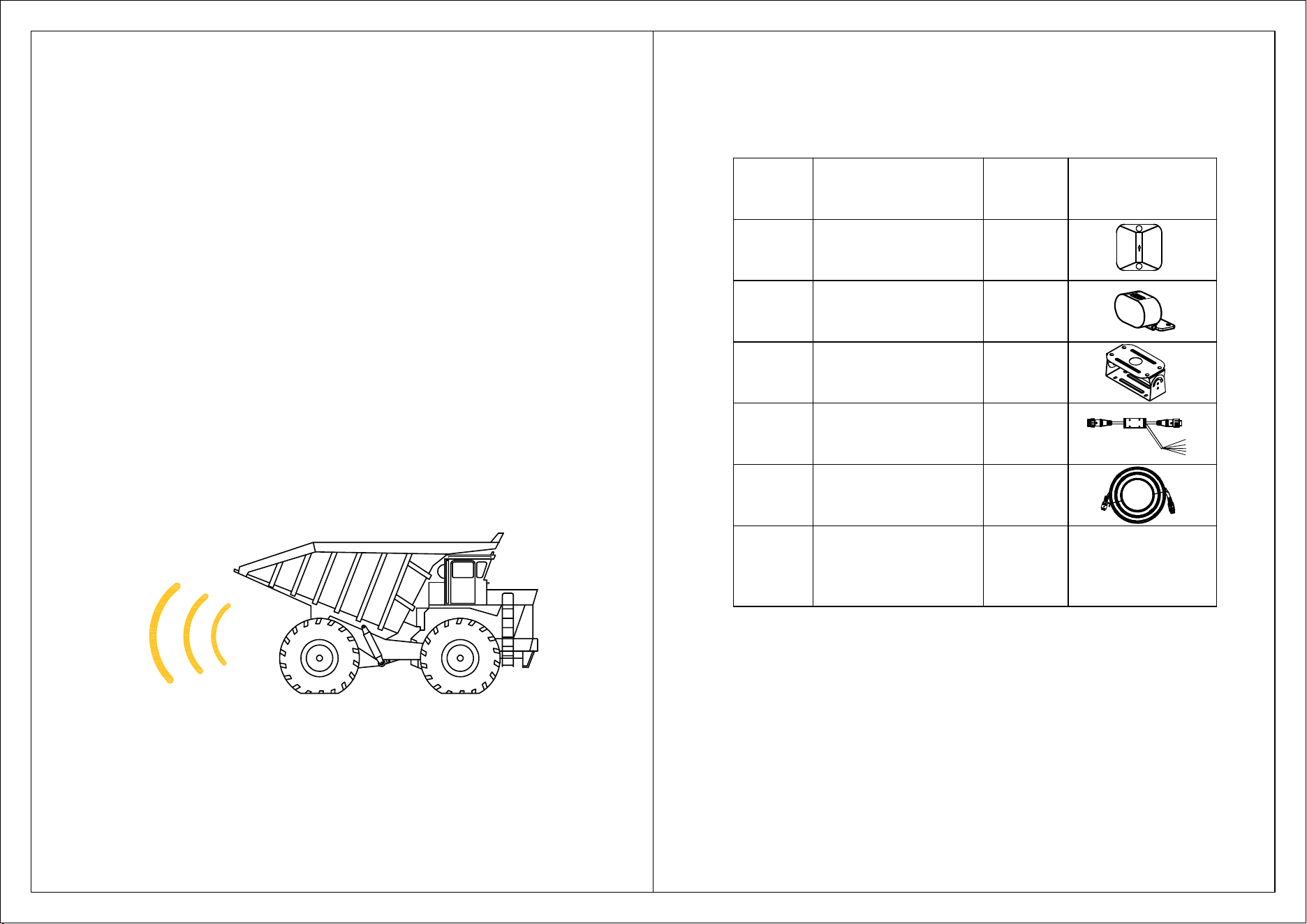
Object detection radar means a system to detect and inform the
driver of the presence of objects in the close-proximity blind-spot
back of the vehicle
,
if deemed necessary based on manufacturer
strategy, warn the driver of a potential collision.
Page 1 of 9
Page 2 of 9
2.Kit Contents
No. Item
QTY.
Image
1
Radar sensor
1
1
1
1
LED display
Sensor bracket
Extension cable
1
2
3
4
5
6
Accessories bag 1
Main Harness
2
M3*8 screw 4pcs
M5*12 screw 4pcs
M4.8*16 screw 4pcs
M5*16 screw 3pcs
Cable Tie 10pcs
Double side tape 1pc
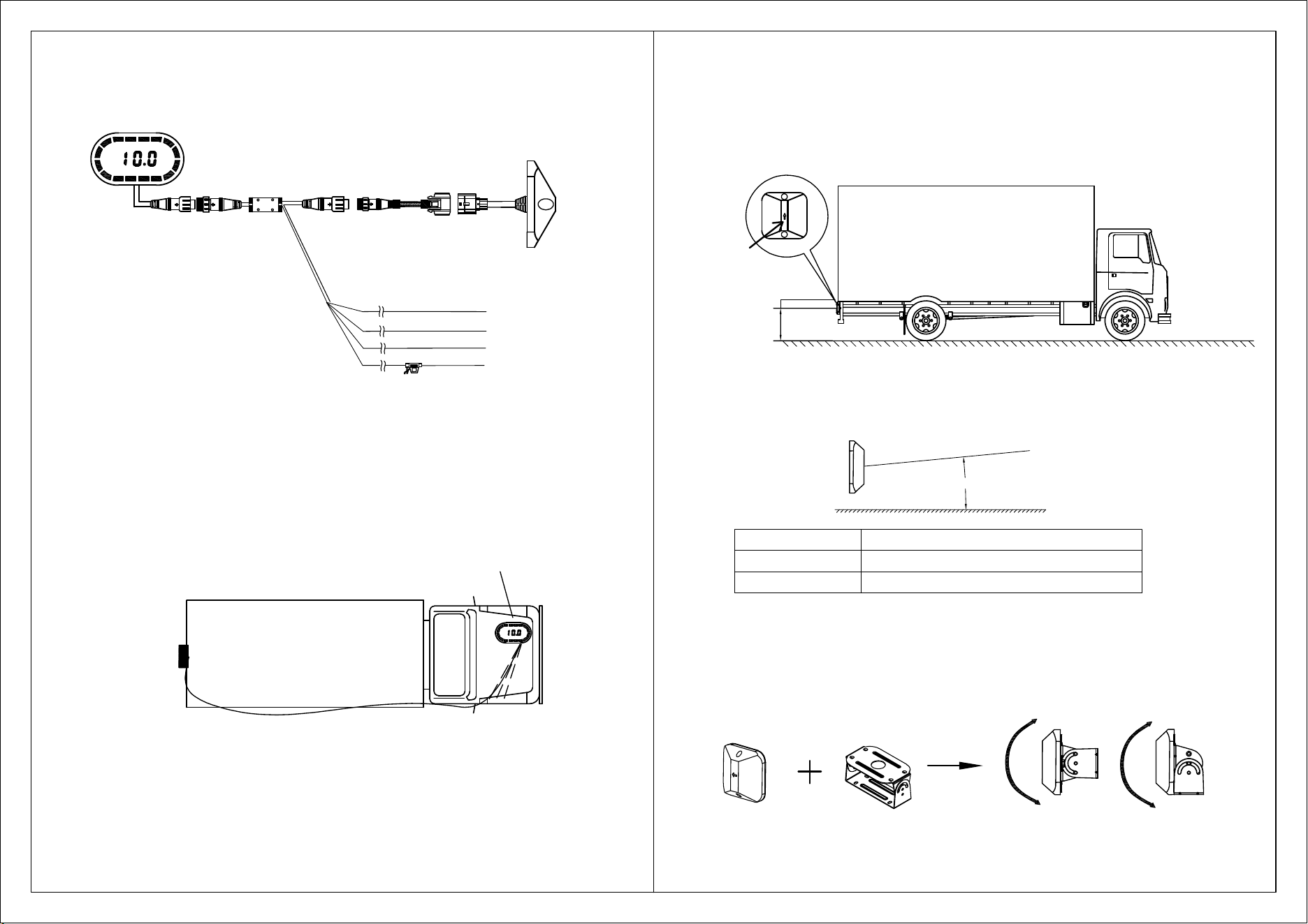
3. Harness Layout
P
age 3 of 9
Note:
1.If the output cable won't be used, please wrap the cable
to avoid short circuit.
2.The output is positive, the Max. output voltage is no
more than 5V.
4. System Layout
D
i
s
p
l
a
y
R
e
a
r
S
e
n
s
o
r
I
G
N
/
A
C
C
G
N
D
R
e
v
e
r
s
e
O
u
t
p
u
t
O
u
t
p
u
t
(
Y
e
l
l
o
w
)
R
e
v
e
r
s
e
l
i
g
h
t
w
i
r
e
(
W
h
i
t
e
)
G
N
D
(
B
l
a
c
k
)
I
G
N
/
A
C
C
(
R
e
d
)
Display
R
e
a
r
S
e
n
s
o
r
Page 4 of 9
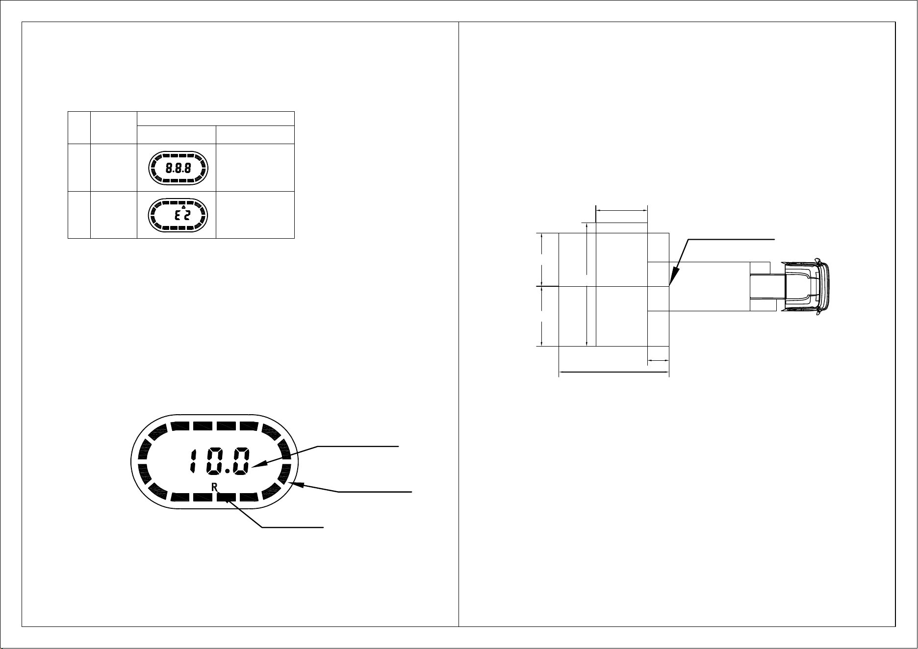
5. Installation
5.1 Installation height
Upward angle
9°
Installation height
0.6 - 0.75m
0.75 - 1.3m 7°
Upward angle
The radar is installed on the vehicle body with a bracket, and the vertical installation
angle is adjusted through the mounting bracket.
5.2 Requirements for vertical installation angle
5.3 Sensor fix
Face upward
Option 1
Option 2
0.6~1.3m
6. Function description
6.1 Self-diagnosis
No.
System status
Display warning method
LED bar Buzzer built in
1 Pass Beep once
(
Bi--
)
2
Sensor
Failed
Beep twice
(
Bi-Bi--
)
6.2 Basic function
When the key is turned to ON, the front radar sensor starts to work;
When the Reverse gear is engaged, the front and rear radar sensors both work.
The LED display will provide audible and visible warnings to driver, the warning principles as
below:
(3) Display will provide audible and visible warnings:
The display will show the distance of the detected object, and provide warning beep,
according the warning section; the warning sections are equally divided into 5 stages.
Take the max. detection as 10m, the warning sections will be divided as below:
(1) If there's object being detected, the output cable will provide high level voltage; if there's no
object being detected, it will output float;
(2) If the reverse gear is engaged
,
the display will show the nearest distance of rear detected
object;
Object distance
LED Color bar
Rear object
Page 5 of 9
Page 6 of 9
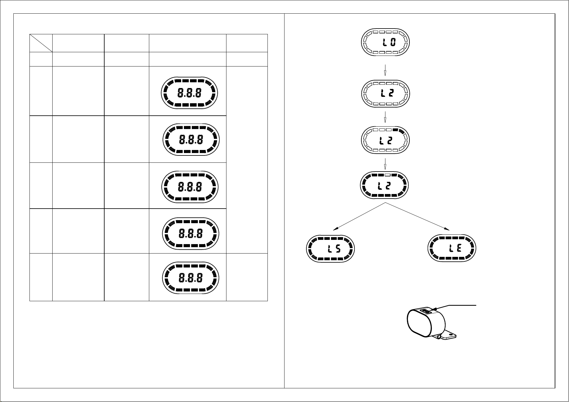
6.3 Learning function
When the installation position of the radar is not at the outermost side of the vehicle,
the radar is easy to detect the accessories of the vehicle or vehicle body, which will
result in false alarm. Therefore, in order not to make false alarm, it is necessary to
enter into the learning mode to make the radar ignore the object.
Users need to follow the following steps to realize the learning function:
a.Move the vehicle to an open area and confirm that there are no obstacles other than
body accessories within (a*b)m of the radar;
(1) a1
>
4*L1
,
and a1
>
3m
;
(2) b1
>
W1+W2
,
and b1
>
6m
;
b.Power on the system and wait for the completion of system self diagnosis;
c.Constantly press the setup button for 3.0s-4.5s, the buzzer will beep once, the display
will show "L0", and enter into the automatic learning function setup mode; Release the
button, and then briefly press the key to make the display shows "L2", the system enters
into the automatic learning mode, and the learning results are shown after the learning
process is completed. If "LS" is shown and beeps once, the learning is successful; if "LE"
is shown and beeps twice, the learning is failed.
L2
L1
a1
b1
W1
W2
Rear sensor
installation position
Page 7 of 9
Item
No.
Object distance Distance showing Color bar showing Beep frequency
1
No detection
— —
No. showing No beep
2
6.1 - 10.0m 6.1-10.0
Green LED bar
3
4.1 - 6.0m 4.1 - 6.0
Yellowish green LED bar
4
2.1 - 4.0m 2.1 - 4.0
Yellow LED bar
5
0.81 - 2.0m 0.81 - 2.0
Orange LED bar
6
Red LED bar
≤0.8m
-P-
Constant beep
BI-----BI-----BI
BI--BI--BI
BIBIBI
The closer the
distance,the
faster the warning
frequency
Note
:
Above tracing LED display figure is alarm distance 10m as a reference.
No.3,4,5,6 color bar alarm showing segmentation can be setup by setup tool;
No.2 color bar alarm showing segmentation is the maximum alam distance value.
Page 8 of 9
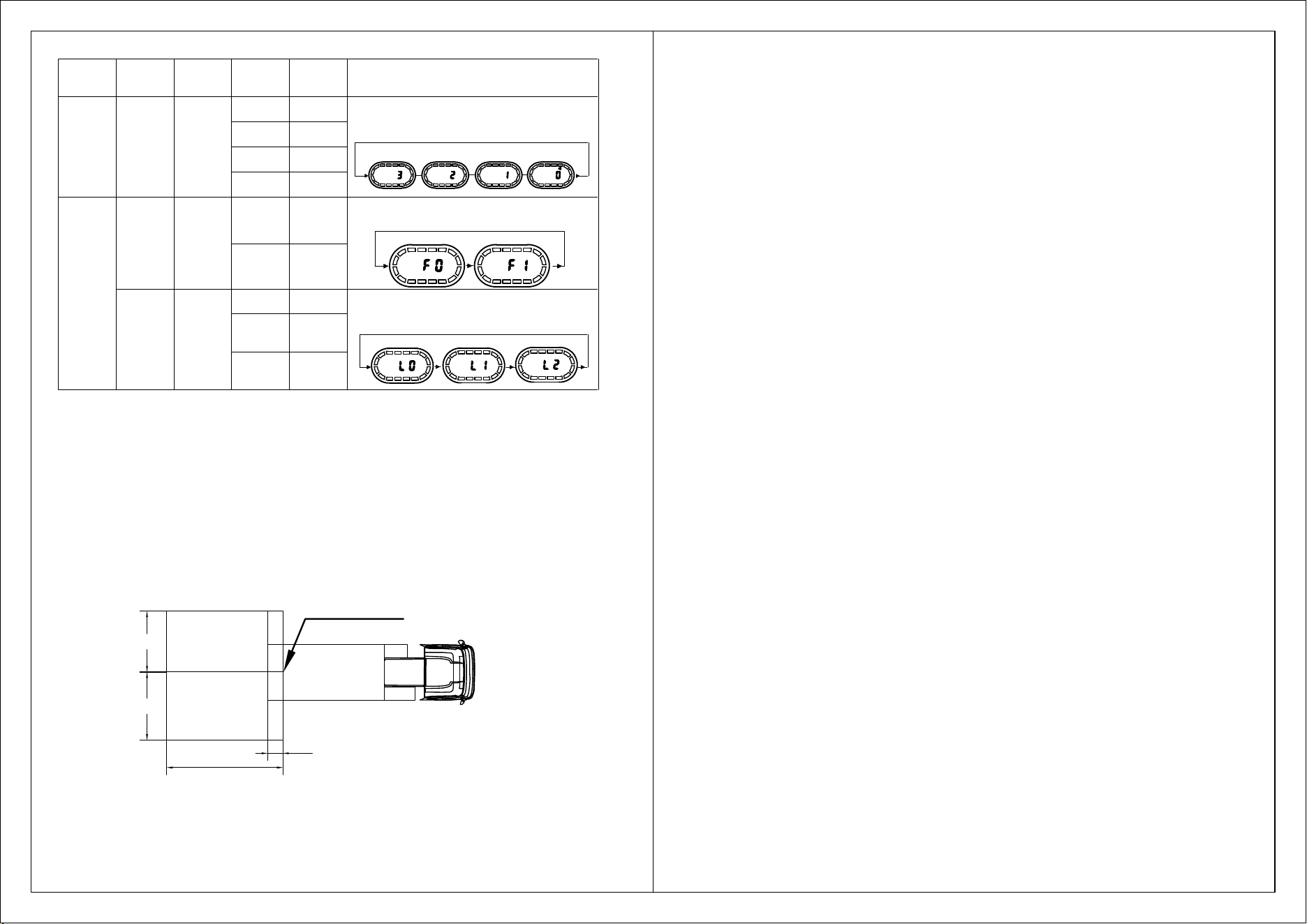
7. Display setup
Setup button
Learning success
Beep once
Learning fail
Beep twice
Press and hold the setup
button for 3.0s-4.5s, and
release it once L0 appears.
Then press the button to show L2.
Enter into learning mode
Show progress bar
Page 9 of 9
8. Detection range setup
The detection range of the sensor is shown in the drawing below. For different vehicle models and
conditions, the detection area can be configurated by handheld setup tool:
L1: Setup for the protruding object in the front of the vehicle , the distance from the sensor installation
position to the front most part of the vehicle: default value=0m;
L2: Warning distance: default value=10m (setup range 1-50m, accuracy 0.1m);
W1: Right side detection width: default value=2m (setup range 1-5m, accuracy 0.1m);
W2: Left side detection width: default value=2m (setup range 1-5m, accuracy 0.1m).
L2
L1
W1
W2
Rear sensor
installation position
Setup button
Button
pressing
time
Setting
function
LED bar
showing
Definition
Remark
Volume
button
0-1.5s Volume
0 OFF
1 Low
2 Middle
3 High
Setup
button
0s-1.5s
Imperial VS
Metric
display
F0
F1
1.5s-3.0s
Automatic
learning
function
L0 OFF
L2
Front sensor
automatic
learning
Shortly press the setup button, the buzzer will beep once and enter into the volume
adjustment mode, the display will show the current volume; Each time you press the
setup button, 3, 2, 1 and 0 cycle, stop pressing, and the display will automatically
save the status and exit.
Metric
Imperial
Constantly press the setup button the buzzer will beep once and enter into the
display system setting mode, and the display will show the current status; Each time
you press the setup button, F0 and F1 cycle, after stop pressing, and automatically
save the status and exit.
Constantly press the setup button the buzzer will beep once and enter into the
display system setting mode, and the display will show the current status; Each time
you press the setup button, L0, L1 and L2 cycle, after stop pressing, and
automatically save the status and exit.
L1
Rear sensor
automatic
learning
FCC WARNING
This device complies with part 15 of the FCC Rules. Operation is subject to the
following two conditions: (1) This device may not cause harmful interference, and
(2) this device must accept any interference received, including interference that
may cause undesired operation.
Any changes or modifications not expressly approved by the party responsible for
compliance could void the user's authority to operate the equipment.
This equipment has been tested and found to comply with the limits for a Class B
digital device, pursuant to part 15 of the FCC Rules. These limits are designed to
provide reasonable protection against harmful interference in a residential
installation. This equipment generates, uses and can radiate radio frequency
energy and, if not installed and used in accordance with the instructions, may
cause harmful interference to radio communications. However, there is no
guarantee that interference will not occur in a particular installation. If this
equipment does cause harmful interference to radio or television reception, which
can be determined by turning the equipment off and on, the user is encouraged to
try to correct the interference by one or more of the following measures:
—Reorient or relocate the receiving antenna.
—Increase the separation between the equipment and receiver.
—Connect the equipment into an outlet on a circuit different from that to which the
receiver is connected.
—Consult the dealer or an experienced radio/TV technician for help.
FCC Radiation Exposure Statement
This equipment complies with FCC radiation exposure limits set forth for an
uncontrolled environment.
This transmitter must not be co‐located or operating in conjunction with any other
antenna or transmitter.
This equipment should be installed and operated with minimum distance 20cm
between the radiator& your body.