Robotic arm user manual
401BOT-1
Operating Instructions
There are a total of 8 installation videos, with the following functions:
Video 1: Duration 7:46, wiring and installation
Video 2: Duration 1:56, main motor rotation test
Video 3: Duration 0:59, LED light strip test
Video 4: Duration 1:59, limit switch test
Video 5: Duration 1:18, emergency stop switch test
Video 6: Duration 3:12, manual test of motor rotation encoder
Video 7: Duration 5:30, GPIO pulse output test
Video 8: Duration 1:55, mechanical arm gripper motor test
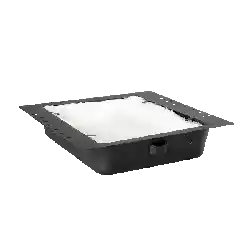
Test
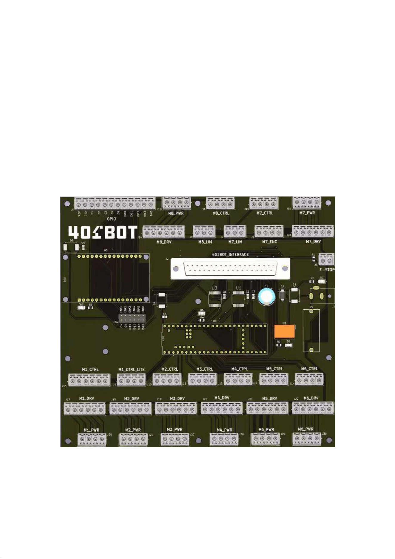
board
大板
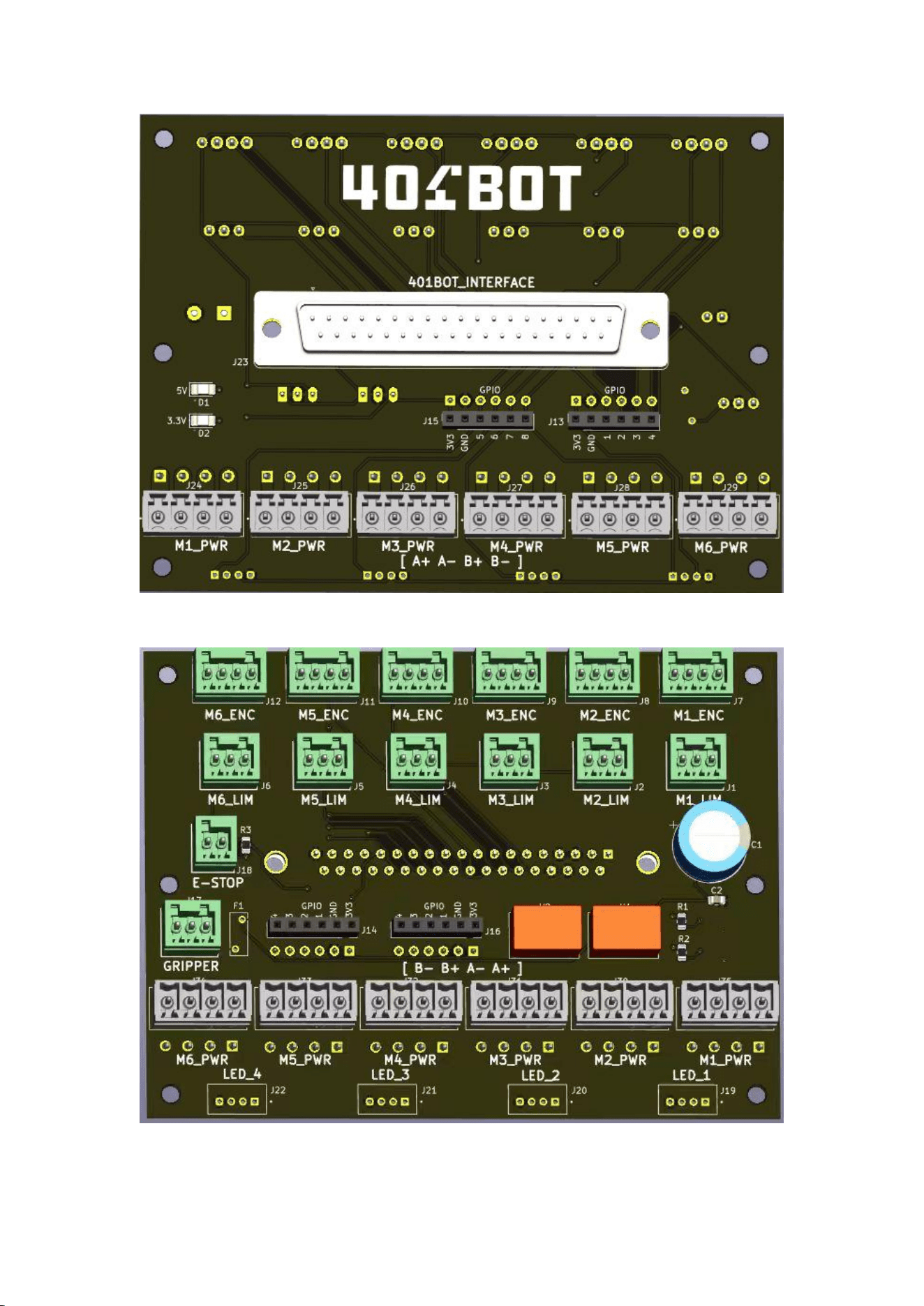
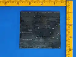
小板正面
The reverse side of the small board
Test program installation
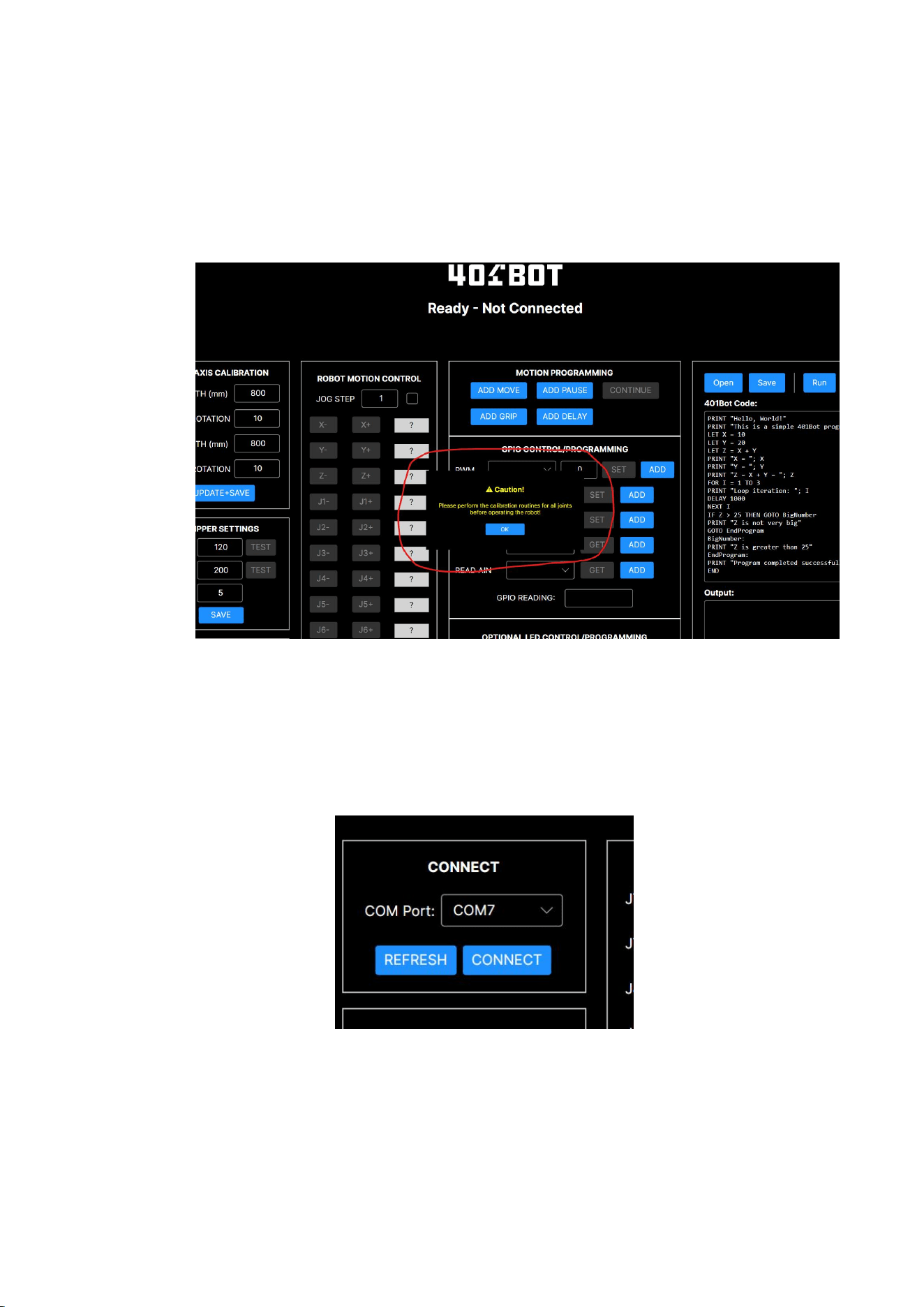
Copy the test program RobotController.exe directly to the hard disk and click to open and
run it. At the same time, connect a 24V power supply and use a Micro USB cable to
connect the mainboard (Teensy module) to the computer.
When the program starts, it will prompt you to calibrate. Please ignore it and just tap OK
to continue.
Click the REFRESH button in the CONNECT area at the top left
corner of the program to update the serial port number of the
system (note that COM7 in the picture below is just an example; it
may vary depending on the computer). Then click the CONNECT
button to connect the motherboard.

Wiring Installation Instructions
Reference Video 1:
(a) Connect the DB37 cable from the large board to the front of the small board.
(b) Connect a 6-pair 6 motor power cable from the large board's (M1_PWR,
M2_PWR) interface to the (M1_PWR, M2_PWR) interface on the front of the small
board.
(c) Connect 6 cables with limit switches to the M1_LIM ~ M6_LIM interfaces on the
back of the small board.
(d) Connect a cable with a stop switch button to the E-STOP interface on the back of
the small board.
(e) Connect the motor with the J1 TEST MOTOR label to the M1_PWR interface on
the back of the small board.
(f) Connect the motor with the J2 TEST MOTOR label to the M2_PWR (MOTOR-J2
cable) and M2_ENC (ENCODER-J2 cable) on the back of the small board.
(g) Connect the LED strip board to the LED_2 interface on the back of the small
board.
(h) Connect the clamp motor to the GRIPPER interface on the back of the small
board.
(i) Install the driver box with the J1 TEST DRIVER label onto the main board.
#Note# The areas below the driver box (GND, +Vdc, A+, A-, B+, B-) are connected to
the M1_DRV interface.
The areas above the driver box (PUL+, PUL-, DIR+, DIR-, ENA+, ENA-) are connected
to the M1_CTRL_HD interface.
(j) Install the driver box with the J2 TEST DRIVER label onto the main board.
The cable below the driver box (GND, +Vdc, A+, A-, B+, B-) is connected to the
M2_DRV interface.
#Note# The cables above the driver box (PUL, DIR, ...) are connected to the M2_CTRL
interface.
(k) Connect a DC 24V power supply to the J1 of the main board, and a Micro USB
(Teensy module) to the computer.
2. Output Test
(a) Main Motor Test
Press the buttons J1-, J1+, J2-, and J2+ in the test program. The main motor will start
to rotate. Refer to Video 2
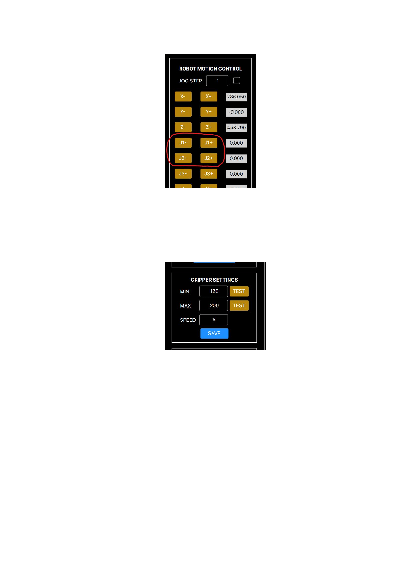
(a) Clasp Motor Test
Press the TEST button in the GRIPPER SETTINGS section. The clasp motor will start
rotating. Refer to Video 8
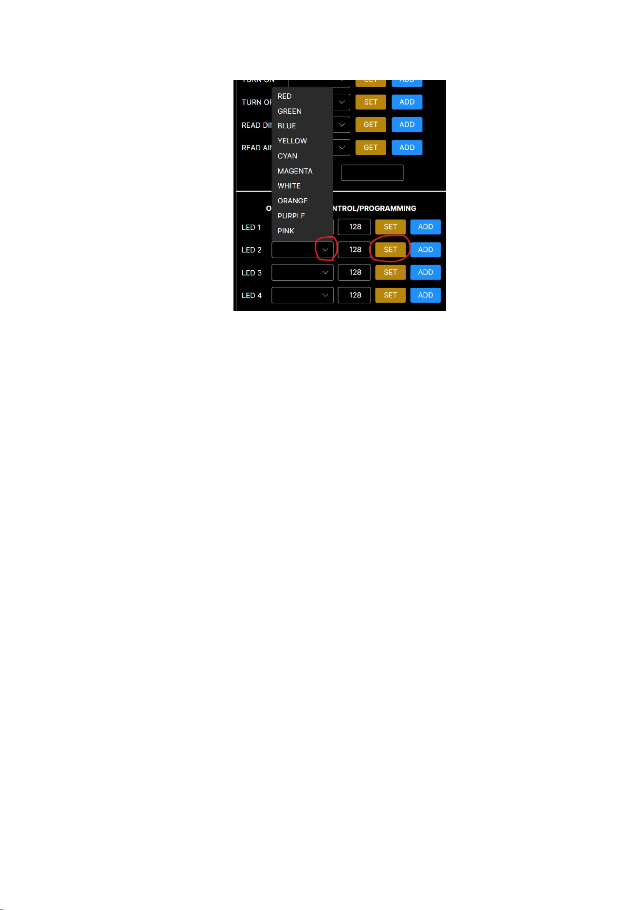
(a) LED Strip Testing
In the OPTIONAL LED CONTROL/PROGRAMMING section, open the sliding window
for LED2.
After selecting the color, press the SET button, and the LED strip will change its color.
Refer to Video 3
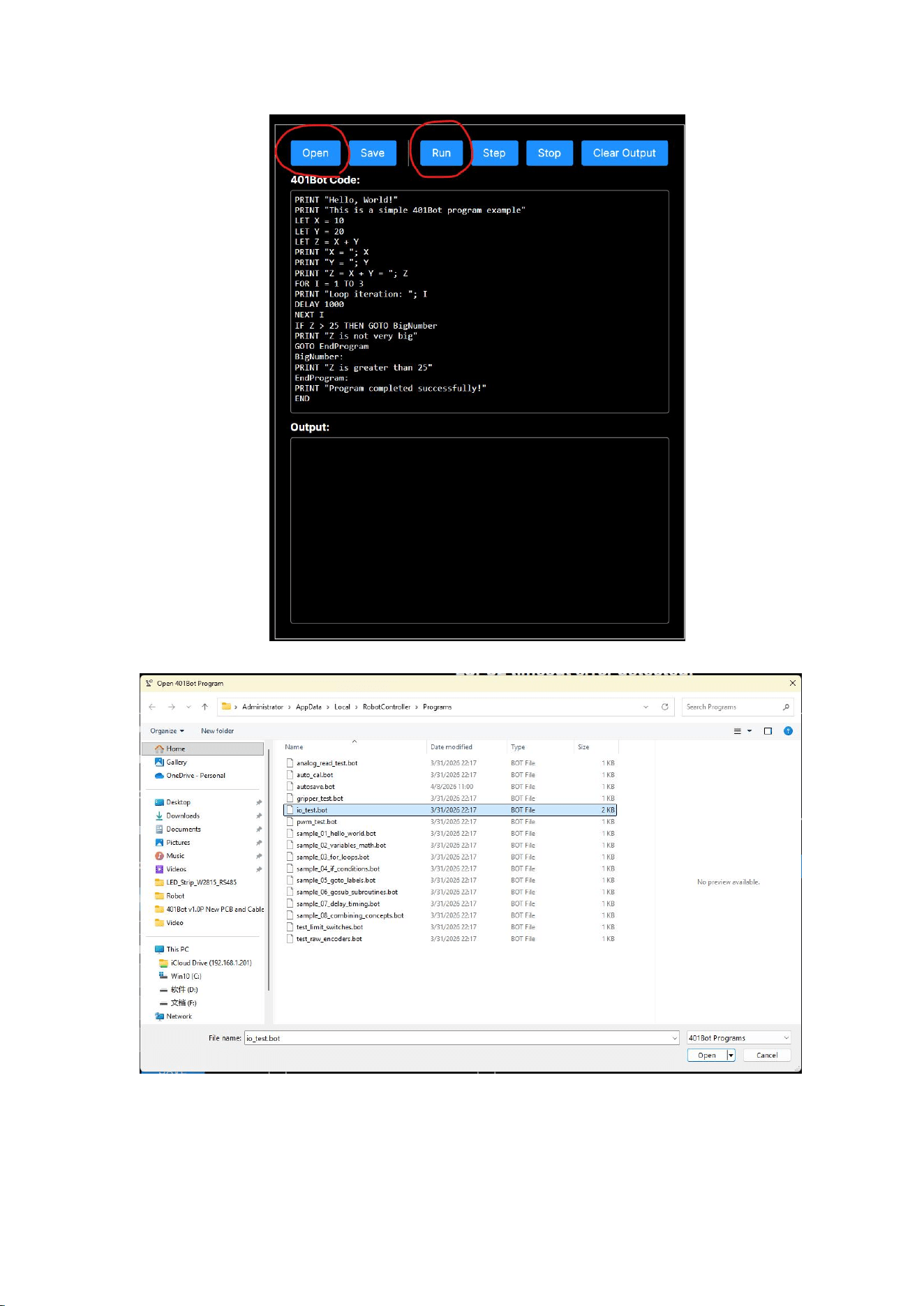
(a) GPIO Pulse Output Test
On the right side of the test program, you can load the sample program. Click
"OPEN" to find "io_test.bot", then open it. Click the "RUN" button, and the sample
program will output a 3.3V pulse to the GPIO port. Refer to Video 7.
Input test
(a) Test of limit switches and emergency stop switches
Click on "OPEN" to open the sample program. Locate "test_limit_switches.bot" and open it. Click
on the "RUN" button, and the program will start reading the status of the limit switches and
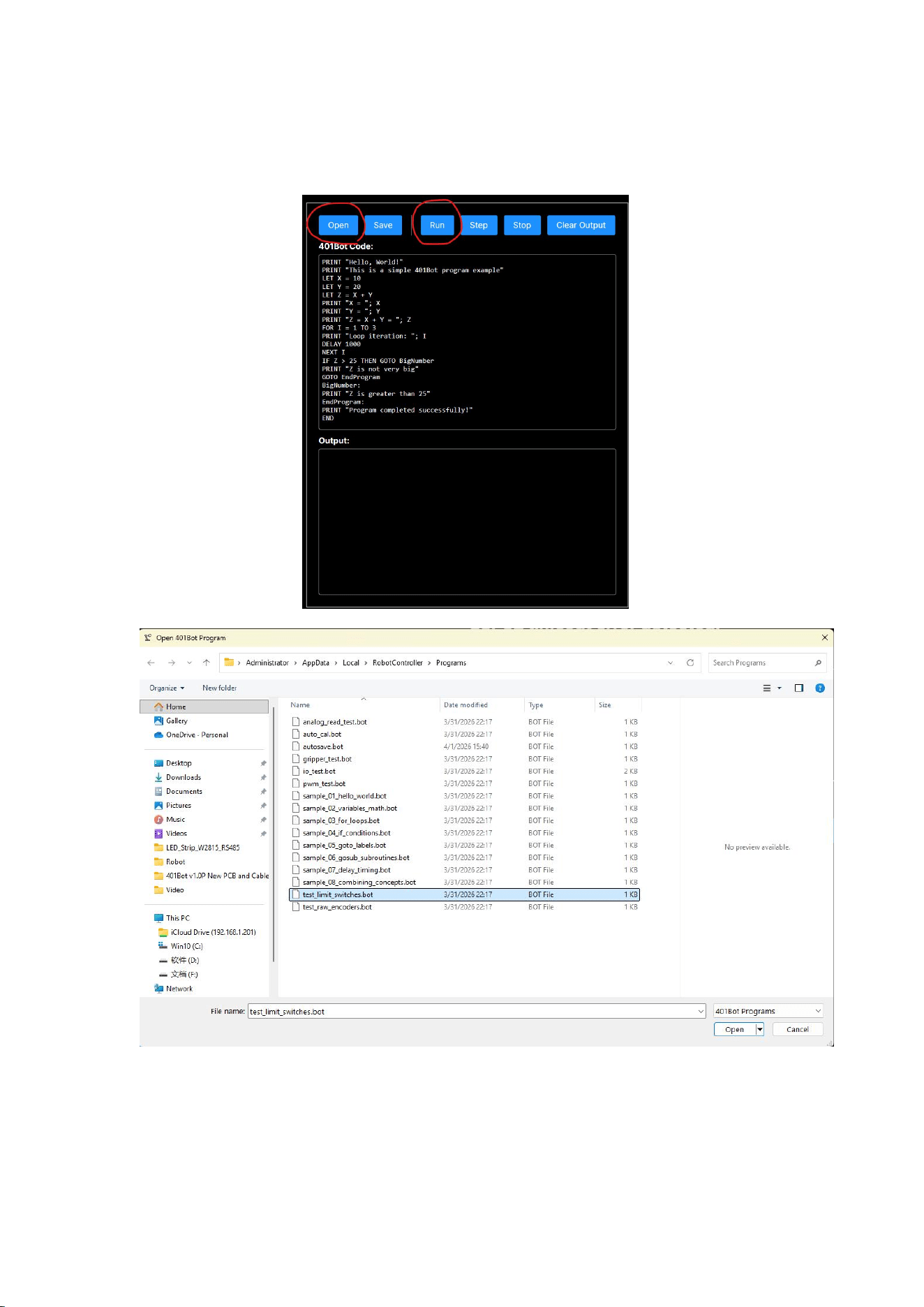
display the results in the lower window. Refer to Video 4.
Press the emergency stop switch, and the execution window of the example program below will
show the stop status. Refer to Video 5.
(a) Motor rotation encoder test
#Attention# This test requires manual rotation of the motor. Therefore, the M2_PWR
interface on the motherboard must be unplugged. Please refer to Video 6.
Click on "OPEN" to open the sample program. Locate "test_raw_encoders.bot" and
open it. Click on the "RUN" button. The program will start reading the status of the
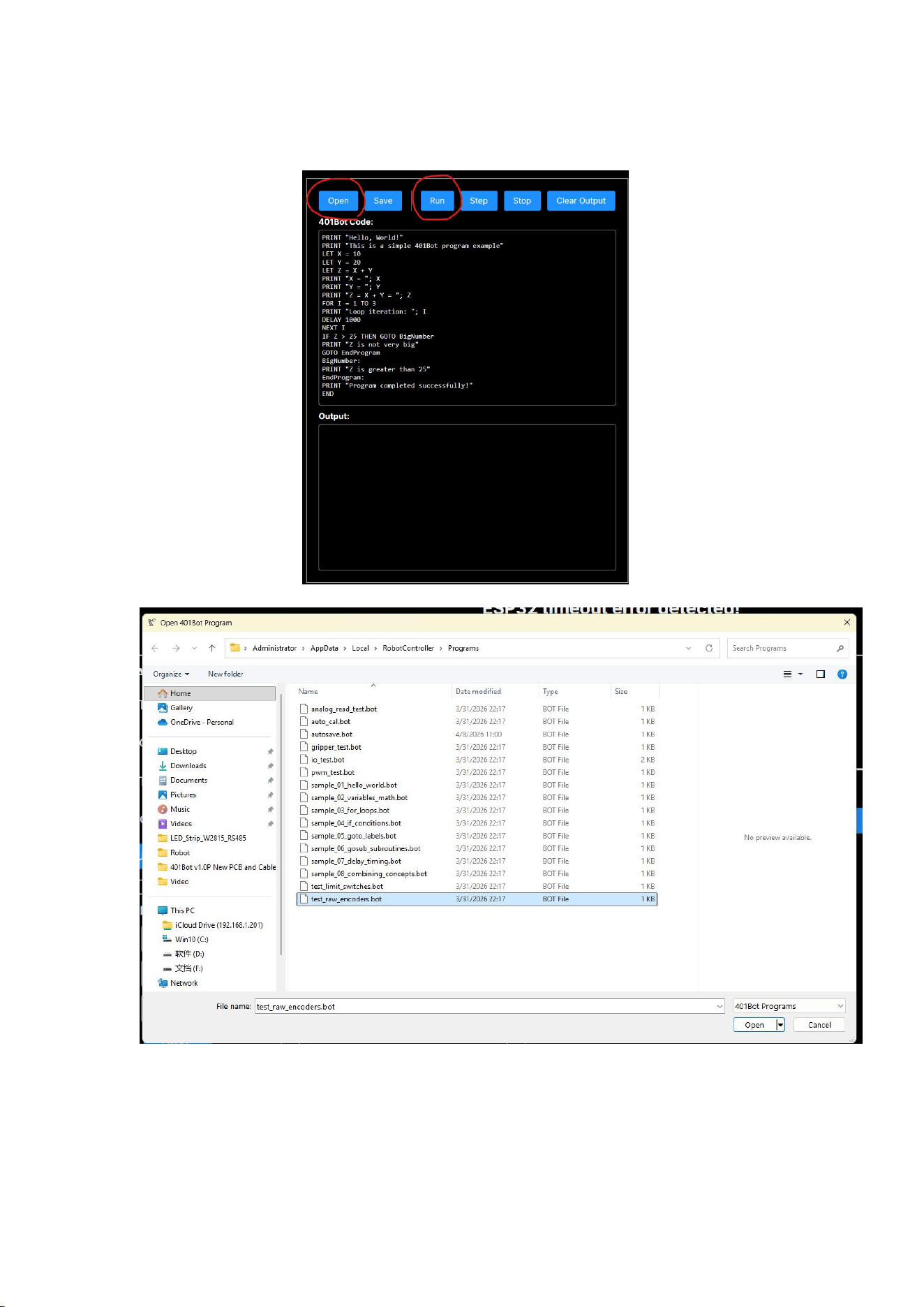
rotary encoders. When you manually rotate the J2 motor, there will be an output
reflected in the lower execution window.

FCC Statement
This device complies with part 15 of the FCC rules. Operation is subject
to the following two conditions: (1) this device may not cause harmful
interference,
and(2) this device must accept any interference received, including
interference that may cause undesired operation.
Changes or modifications not expressly approved by the party responsible
for compliance could void the user's authority to operate the equipment.
NOTE: This equipment has been tested and found to comply with the
limits for a Class B digital device, pursuant to part 15 of the FCC Rules.
These limits are designed to provide reasonable protection against
harmful interference in a residential installation.
This equipment generates uses and can radiate radio frequency energy
and, if not installed and used in accordance with the instructions,
may cause harmful interference to radio communications.
However, there is no guarantee that interference will not occur in a
particular installation.
If this equipment does cause harmful interference to radio or television
reception, which can be determined by turning the equipment off and
on,
the user is encouraged to try to correct the interference by one or more
of the following measures:

●
Reorient or relocate the receiving antenna.
●
Increase the separation between the equipment and receiver.
●
Connect the equipment into an outlet on a circuit different from that
to which the receiver is connected.
●
Consult the dealer or an experienced radio/TV technician for help.
This equipment complies with FCC radiation exposure limits set forth
for an uncontrolled environment.
This equipment should be installed and operated with minimum
distance 20cm between the radiator & your body.
ISED Statement
warning:
- English: This device complies with Industry Canada license‐exempt RSS standard(s).
Operation is subject to the following two conditions:
(1) This device may not cause interference,
and (2) This device must accept any interference, including interference that may cause undesired
operation of the device. The digital apparatus complies with Canadian CAN ICES‐003 (B)/NMB
‐3(B).
- French: Le présentappareilestconforme aux CNR d'Industrie Canada applicables aux appareils
radio exempts de licence. L'exploitationestautorisée aux deux conditions suivantes:
(1) l'appareil ne doit pas produire de brouillage, et (2) l'utilisateur de l'appareildoit accepter tout
brouillageradioélectriquesubi, mêmesi le brouillageest susceptible d'encompromettre le
fonctionnement.
L'appareil numérique est conforme à la canadienne CAN ICES‐003 (B)/NMB‐3(B).
This radio transmitter (ISED certification number: 35421-401BOT1) has been approved by
Industry Canada to operate with the antenna types listed with the maximum permissible gain
indicated.
Antenna types not included in this list, having a gain greater than the maximum gain indicated for
that type, are strictly prohibited for use with this device.
Le présent émetteur radio (ISED certification number: 35421-401BOT1) a été approuvé par
Industrie Canada pour fonctionner avec les types d'antenne énumérés ci-dessous et ayant un gain
admissible
maximal.

Les types d'antenne non inclus dans cette liste, et dont le gain est supérieur au gain maximal
indiqué, sont strictement interdits pour l'exploitation de l'émetteur.
Radiation Exposure Statement
This equipment complies with ISED radiation exposure limits set forth for an uncontrolled
environment.
This equipment should be installed and operated with minimum distance 20cm between
the radiator & your body.
Cet équipement est conforme aux limites d'exposition aux rayonnements ISED établies
pour un environnement non contrôlé.
Cet équipement doit être installé et utilisé avec une distance minimale de 20 cm entre le
radiateur et votre corps.