


2
Table of Contents
Usage Notices
5 Precautions for Repair
6 ESD (Electrostatic Discharge) Precautions
7 Instructional Icons
Software Update
8 Updating Software through FOTA
8 Software Update Failure
8 Updating Software through Smart Switch
9 Recovering from a Software Update Failure
9 Recovering on Another Computer
10 Performing a Factory Data Reset
Quality Test
12 Quality Test Using the Samsung Members App
12 Device Diagnostics
13 Test Items
Calibrations
22 Calibrations
22 Used Parts and Calibration Functions in Supported Models
23 Using the Self Repair Assistant App
28 Optical Fingerprint Sensor Calibration
31 Resetting the Battery Cycle Count
34 Range Sensor Calibration

3
Table of Contents
36 Touch Screen Panel Calibration
38 Speaker Calibration
40 Under-display Camera Calibration (Fold Models Only)
42 Digital Hall Sensor Calibration (Fold and Flip Models Only)
Exploded View and Parts List
45 Exploded View
46 Parts List
Disassembly and Assembly
47 Tools for Disassembly and Assembly
52 Fasteners (Adhesives and Materials) for Assembly
54 Disassembly and Reassembly for replacement
56 SIM Card Tray
56 Disassembly
57 Reassembly
58 Back Cover
58 Disassembly
63 Reassembly
67 Front Camera
67 Disassembly
72 Reassembly
77 Rear Camera
77 Disassembly
82 Reassembly
86 Charging Port and Microphone
86 Disassembly
89 Reassembly

4
Table of Contents
93 Top Speaker
93 Disassembly
95 Reassembly
99 Bottom Speaker
99 Disassembly
101 Reassembly
104 Volume Button
104 Disassembly
105 Reassembly
106 Side Button (Fingerprint Recognition Sensor)
106 Disassembly
108 Reassembly
110 Screen Module
110 Disassembly
116 Reassembly
123 Screen
123 Disassembly
130 Reassembly
137 Battery
137 Disassembly
141 Reassembly
149 Press
150 Back Cover Press
154 Screen Press
157 Battery Press
162 Directive 2012/19/EU Annex VII Components

Usage Notices
5
Usage Notices
All functionality, features, specifications, and other device information provided in
this document, including but not limited to, benefits, design, pricing, components,
performance, availability, and capabilities of the device are subject to change without
notice. Samsung reserves the right to alter this document or the device described herein
at any time, without obligation to provide notification of such changes.
Precautions for Repair
Samsung is not liable for any damage or defect determined to be caused by repair by
a non-authorised carrier, self repair or non-professional repair of the device. Samsung
is not liable for any resulting damage to the device, or any injury or other device safety
issue caused by any attempt to repair the device which does not follow these repair and
maintenance instructions.
Any damage to the device or defect caused by an attempt to repair the device by any
person other than a Samsung certified carrier will not be covered by the warranty.
•
Use only demagnetised tools that are specifically designed for small electronic
repairs, as most electronic parts are sensitive to electromagnetic forces.
•
Use only high quality screwdrivers when servicing devices. Low quality screwdrivers
can easily damage the heads of screws.
•
Always use genuine replacement parts. Third-party replacement parts may not
function properly and could cause a fire or injury.
•
Some parts, such as sensors (laser AF/proximity/fingerprint), the rear camera,
the TSP (touch panel), speakers, and other components, may need calibration to
guarantee their performance after repair.
•
The performance of the device’s water and dust resistance cannot be guaranteed
when it is repaired by the user or another unskilled worker.
•
If you need to access the failure data of your device or need to get a more detailed
diagnosis, visit a Samsung Service Centre.
•
If you need to replace unsold parts, visit a Samsung Service Centre and receive
further instruction.
•
Before conducting repairs, remember to make backup copies of all important data
stored in the device.

Usage Notices
6
•
Make sure to wear the appropriate safety equipment before carrying out repairs.
Samsung is not responsible for injuries that may occur because of not wearing the
proper safety equipment. Refer to Tools for Disassembly and Assembly for a list of
tools that you will need for assembling and disassembling the device.
•
Repair the device in a safe place.
•
Before repairing the device, make sure the device is turned off. To turn off the
device, press the Volume Down button and the Side button at the same time, or open
the notification panel and tap the Power icon.
•
If the device is damaged, emits smoke, or if you smell something burning, stop using
the device immediately and contact Samsung.
•
It is recommended to use safety equipment such as glasses, gloves, and a mask
when repairing the device.
•
Be careful not to damage the device when removing the back cover.
•
Before assembly, ensure that there are no screws or foreign objects around the
battery.
•
During assembly, check if there are any abnormalities before reattaching the back
cover, and be careful not to damage the battery by hitting or denting it. If the battery
is damaged, visit a Samsung Service Centre.
•
Do not place the device directly into a microwave and heat it.
•
Before repairing your device, make sure its battery is fully discharged.
•
Visit www.samsung.com to view the device information, related material, and safety
information.
ESD (Electrostatic Discharge) Precautions
It is the sudden flow of electricity between two electrically charged objects caused by
contact, an electrical short, or dielectric breakdown. ESD can cause negative effects on
mobile devices, especially electrical parts.
•
It is recommended to use ESD safety (Anti-static) equipment such as an anti-static
wrist strap and gloves, and an ESD safe mat when repairing the device.
•
Increase the airflow to the work area to decrease the chance of accidental static
electricity discharges, as the potential for static electricity discharge may be
increased in low-humidity environments, such as air-conditioned rooms.

Usage Notices
7
Instructional Icons
Warning: situations that could cause injury to yourself or others
Caution: situations that could cause damage to your device or other equipment
Notice: notes, usage tips, or additional information

Software Update
8
Software Update
Updating Software through FOTA
Update your device’s software through the firmware over-the-air (FOTA) service. You can
also schedule software updates.
Launch the
Settings
app and tap
Software update
→
Download and install
.
•
Install now
: Install updates.
•
Schedule install
: Set the time to install updates automatically.
•
You may incur additional charges when updating the software through a mobile
network.
•
If the latest software has been downloaded to the device, these options will not
appear.
Software Update Failure
If your device becomes disconnected from a network before the update is complete, the
update may fail. Reconnect to a network and complete the update.
Updating Software through Smart Switch
You can use Smart Switch to update your device’s software to the latest
version. You must download the desktop version of the Smart Switch app from
www.samsung.com/smartswitch.
•
This feature may not be supported on some devices or computers.
•
Limitations apply. Visit www.samsung.com/smartswitch for details. Samsung
takes copyright seriously.
1 On the computer, visit www.samsung.com/smartswitch to download Smart Switch.
2 On the computer, launch
Smart Switch
.
3 Connect your device to the computer using the device’s USB cable.
4 Click
Update
.

Software Update
9
5 Read the on-screen instructions and click
Continue
.
6 Read the precautions about the update and click
OK
.
7 Read and agree to the terms and conditions.
The update will start.
Recovering from a Software Update Failure
If a software update is interrupted because of an error on your device or computer, your
device may fail to operate normally. If this occurs, you can perform a factory data reset
on your device for emergency recovery.
Before performing the factory data reset, remember to make backup copies of all
important data stored in the device. Samsung is not responsible for the loss of data
stored in the device.
1 Disconnect your device from the computer and launch
Smart Switch
again on the
computer.
2 Click
→
Emergency Software Recovery and Reset
.
The device list will appear.
3 Click the device that experienced a software update error and click
Device reset
→
OK
.
The device will perform a factory data reset.
Recovering on Another Computer
If the emergency recovery process continues to fail on the computer where the software
update failed, you can repair your device on another computer using the recovery code.
This will include a factory data reset of your device.
•
Before performing the factory data reset, remember to make backup copies of
all important data stored in the device. Samsung is not responsible for the loss
of data stored in the device.
•
The recovery code can be found only on the computer where the software
update has failed.
1 On the computer where the software update has failed, launch
Smart Switch
.
2 Click
→
Emergency Software Recovery and Reset
.
Software Update
10
3 On the devices list, click the device that failed to update the software and check the
recovery code.
4 On another computer, launch
Smart Switch
.
5 Click
→
Emergency Software Recovery and Reset
→
Emergency code recovery
.
6 Enter the recovery code and click
OK
.
7 Follow the on-screen instructions to put your device into recovery mode and
complete the emergency recovery.
Performing a Factory Data Reset
The factory data reset restores the device’s default settings. This erases all data,
including files and downloaded apps, from the device.
Before performing the factory data reset, remember to make backup copies of all
important data stored in the device. Samsung is not responsible for the loss of data
stored in the device.
Make sure your device’s battery level is sufficient, as losing power during a factory
reset may result in system problems.
1 Launch the
Settings
app and tap
General management
→
Reset
→
Factory data
reset
.
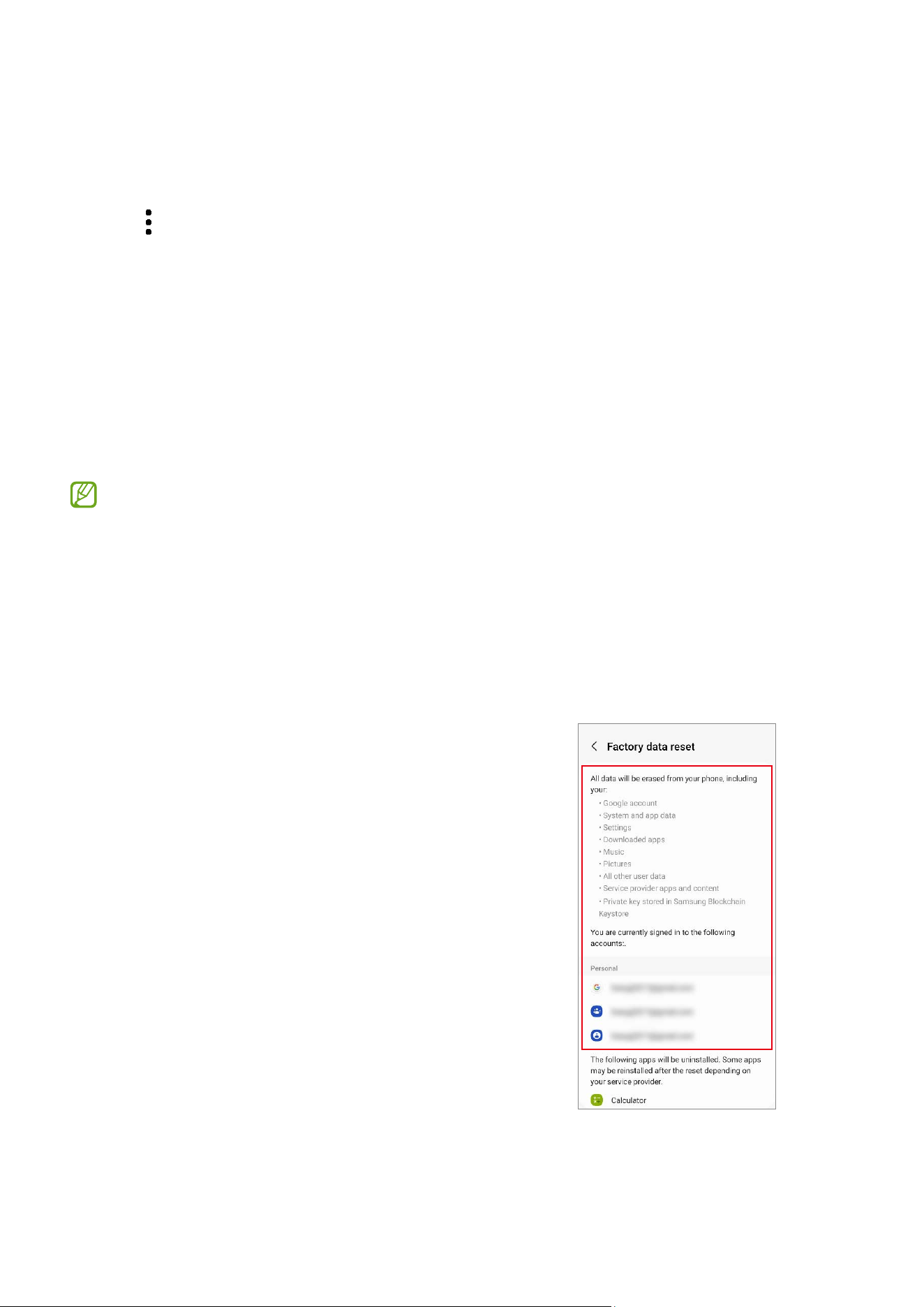
2 Read the on-screen instructions and check
which account you are signed in with.
If your device is signed in to your Google
account, log out of your Google account. If
you do not log out of your Google account,
logging in to another account after the
factory data reset will not be possible,
because your device will be locked.

Software Update
11
3 Tap
Reset
→
Delete all
.
All data will be deleted when rebooting.
During a factory data reset, the device may repeat rebooting and the logo may be
displayed for a long time.
Quality Test
12
Quality Test
Quality Test Using the Samsung Members App
It is recommended to evaluate your device through the Samsung Members app
after it has been repaired to guarantee its performance. If the test results show any
abnormalities or that another malfunction has occurred because of the repair, visit a
Samsung Service Centre to receive further instruction. Any malfunctions caused by your
repair may incur additional repair charges.
•
The Samsung Members app is subject to update without any prior notice.
•
To use this feature, you must sign in to your Samsung account.
•
Some features may not be available depending on the carrier or model.
Device Diagnostics
1 Launch the
Samsung Members
app.
If you do not have the app, download it from the
Galaxy Store
or
Play Store
.
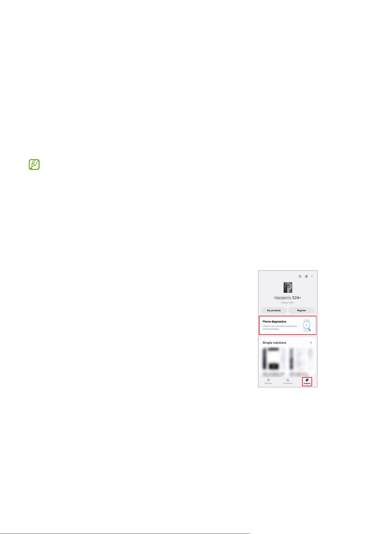
2 Tap
Support
→
Phone diagnostics
.
The diagnostics screen will appear and you can
check the test status and items.
Quality Test
13
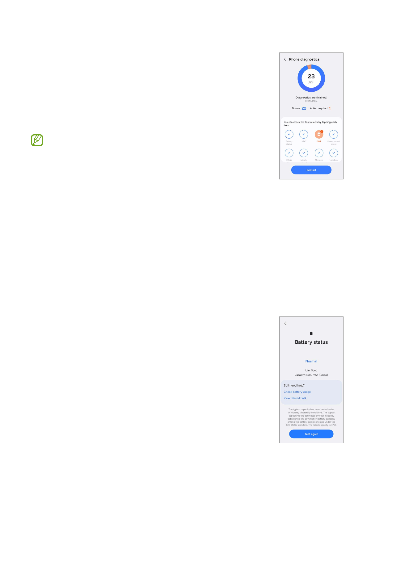
3 Tap
Test all
.
The device performs a test on all items.
When the test is finished, you can check the test
results.
•
Tick mark: Working normally
•
Exclamation mark: Needs further inspection
•
The test proceeds automatically, but you may
need to follow the on-screen instructions
depending on the test item. Keep an eye on
the screen during testing to ensure smooth
progress.
•
If the exclamation mark appears on any test
items after finishing the test, tap them to find
the solutions. If the problem persists, visit a
Samsung Service Centre.
Test Items
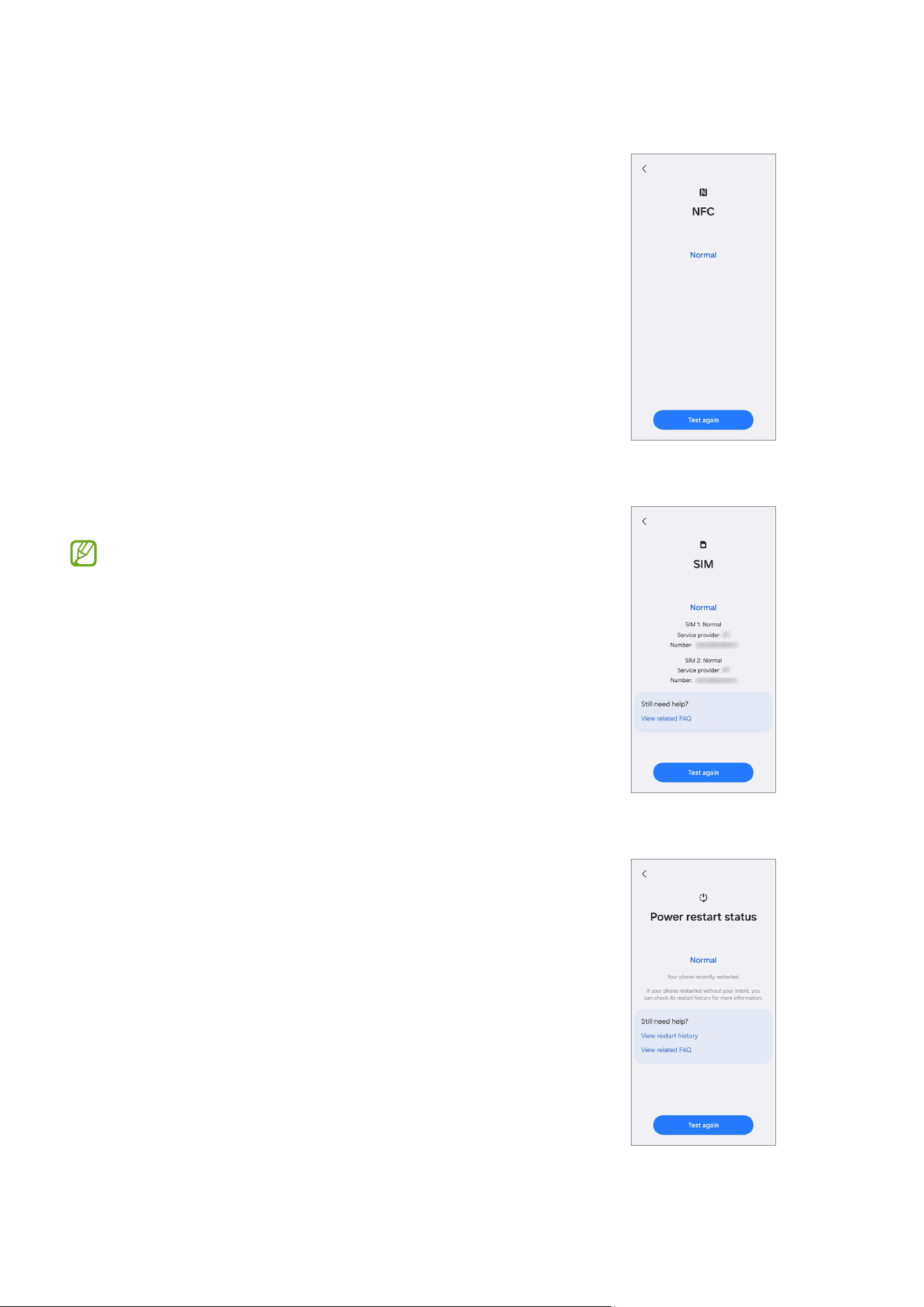
Battery status
Check the battery life and capacity.
Quality Test
14
NFC
Check whether the near field communication (NFC)
feature is working normally.
SIM
Check whether the SIM is working normally.
If the test result is not
Normal
, remove the SIM
card from the SIM card tray and replace it. If
possible, try again with another SIM card.
Power restart status
Check whether the device has restarted within the
last 7 days.
Quality Test
15
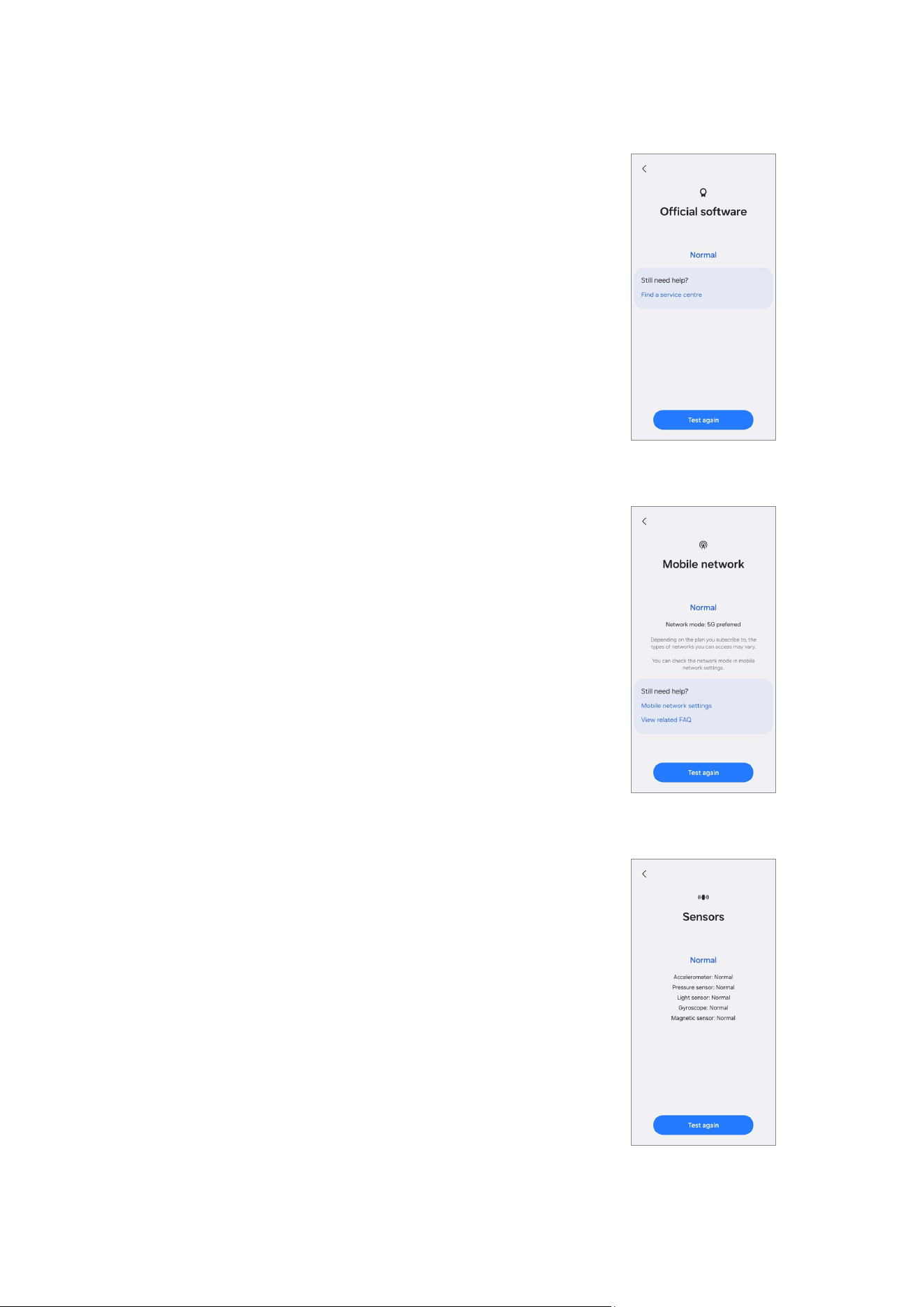
Official software
Check whether the official software is being used.
Mobile network
Check whether your mobile network is working
normally.
Sensors
Check whether the sensors are working normally.
Quality Test
16
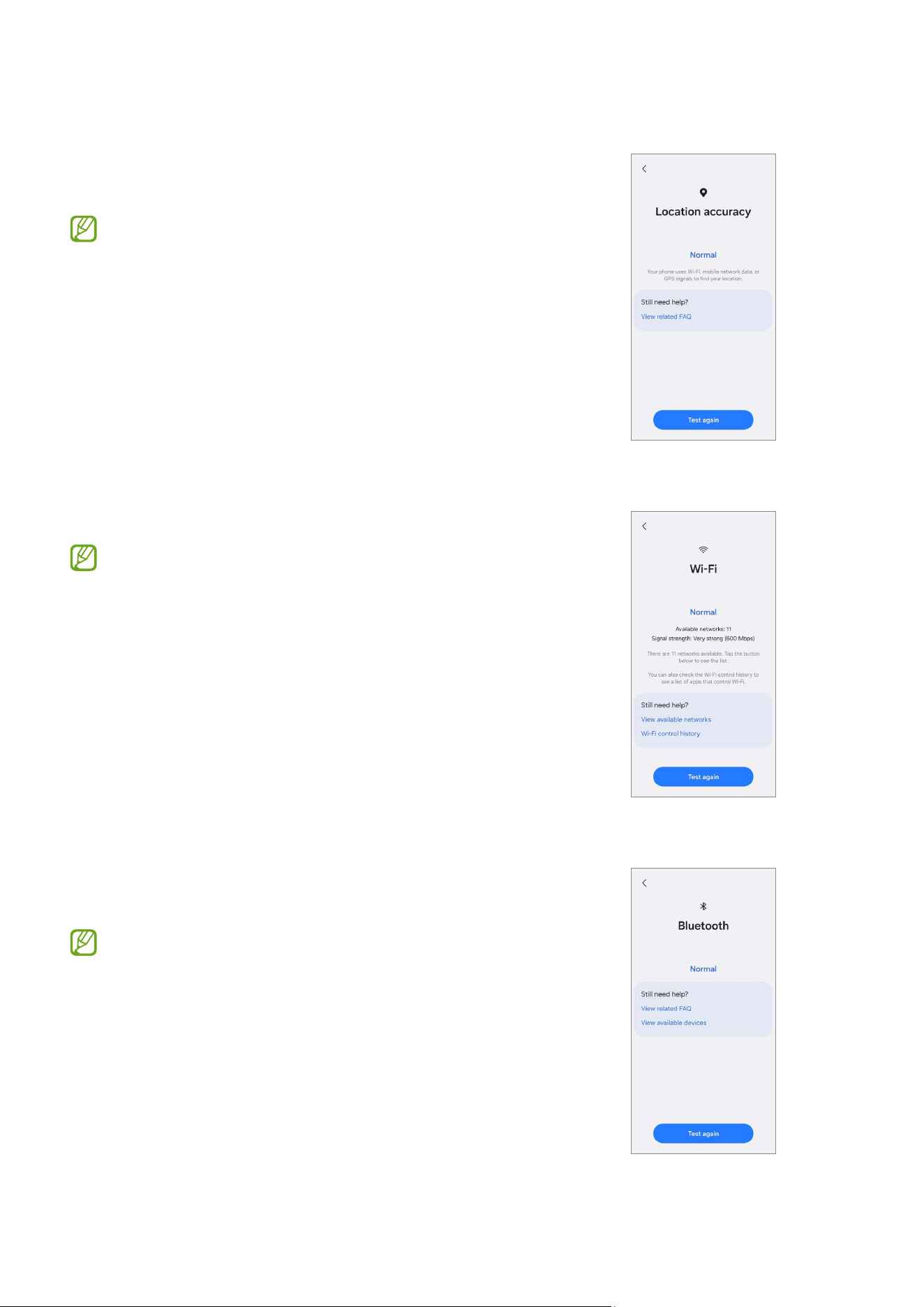
Location accuracy
Check whether the location feature is working
normally.
The results might be more accurate when you
test outside.
Wi-Fi
Check whether the Wi-Fi feature is working normally.
To test this feature, the Wi-Fi feature must be
activated.
Bluetooth
Check whether Bluetooth can search for other
Bluetooth devices.
To test this feature, the Bluetooth feature must
be activated.
Quality Test
17
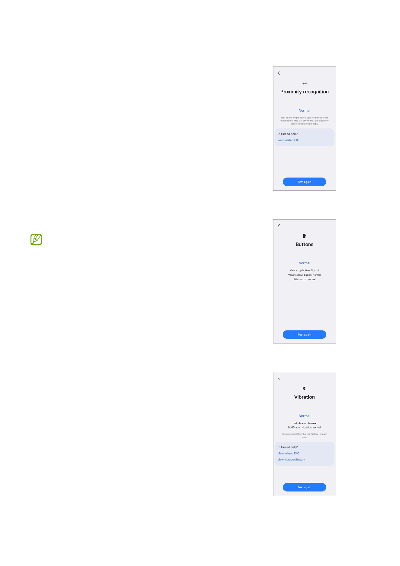
Proximity recognition
Check whether the proximity recognition feature is
working normally.
Buttons
Check whether the buttons are working normally.
Make sure that the buttons are not
contaminated to get more accurate test results.
Vibration
Check whether the vibration feature is working
normally.
Quality Test
18
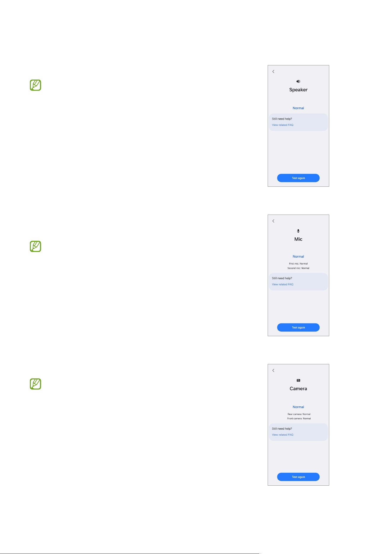
Speaker
Check whether the speakers are working normally.
If you cannot hear the sound well, check
whether the media volume is turned up and if
the speaker is obstructed by foreign objects, the
case, or the protective film.
Mic
Check whether the microphones are working
normally.
•
The number of tests may vary depending on
the model.
•
If you cannot hear anything after recording,
check whether the media volume is turned
up and if the microphone or speaker is
obstructed by foreign objects, the case, or the
protective film.
Camera
Check whether the cameras are working normally.
To test this more accurately, check if the camera
is obstructed by foreign objects, the case, or the
protective film.
Quality Test
19
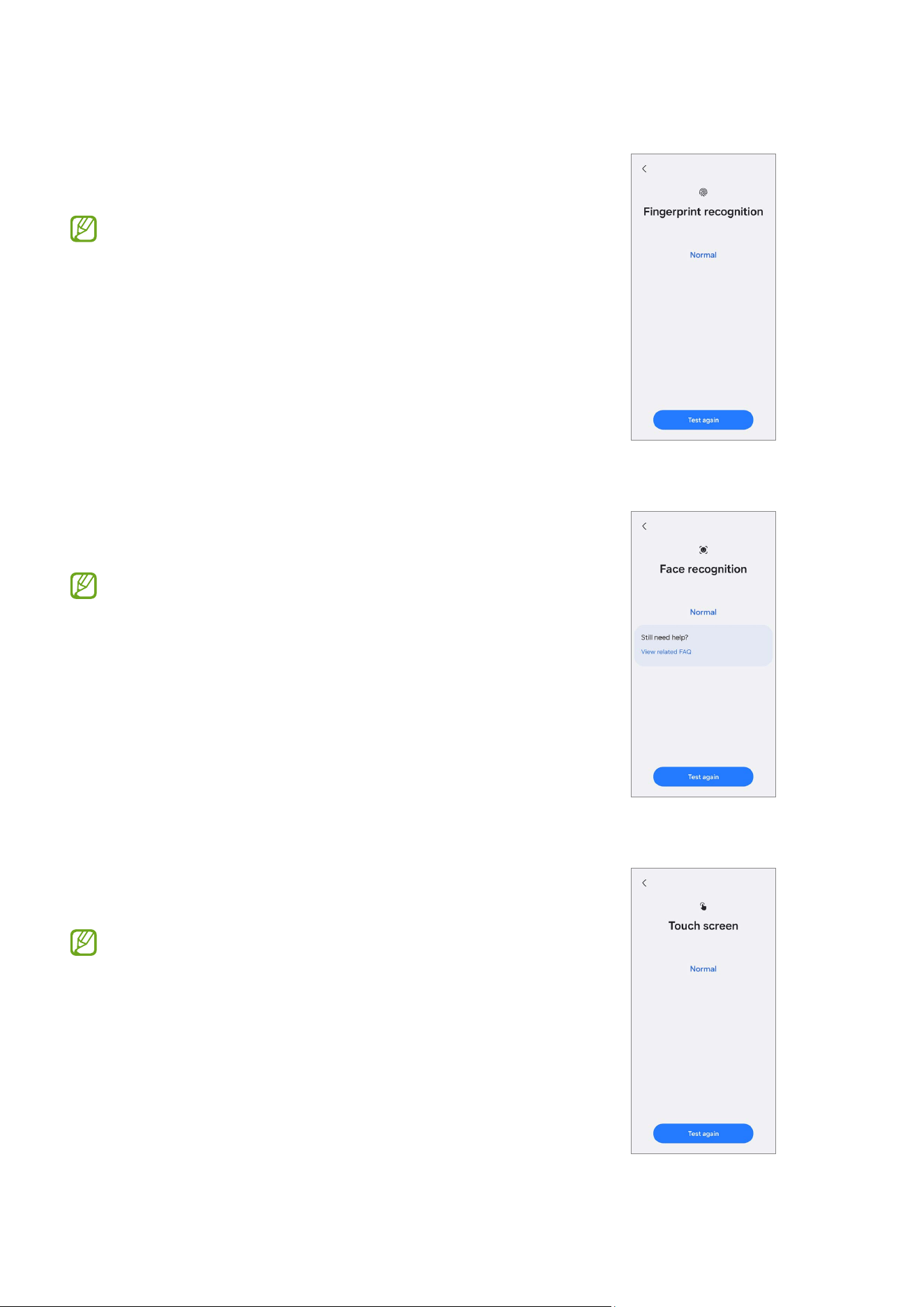
Fingerprint recognition
Check whether the fingerprint recognition sensor is
working normally.
To test this feature, your fingerprint must be
registered.
Face recognition
Check whether the face recognition sensor is working
normally.
To test this feature, your face must be
registered.
Touch screen
Check whether touch inputs are recognised normally
in all areas of the screen.
Make sure that the screen is clean to get more
accurate test results.
Quality Test
20
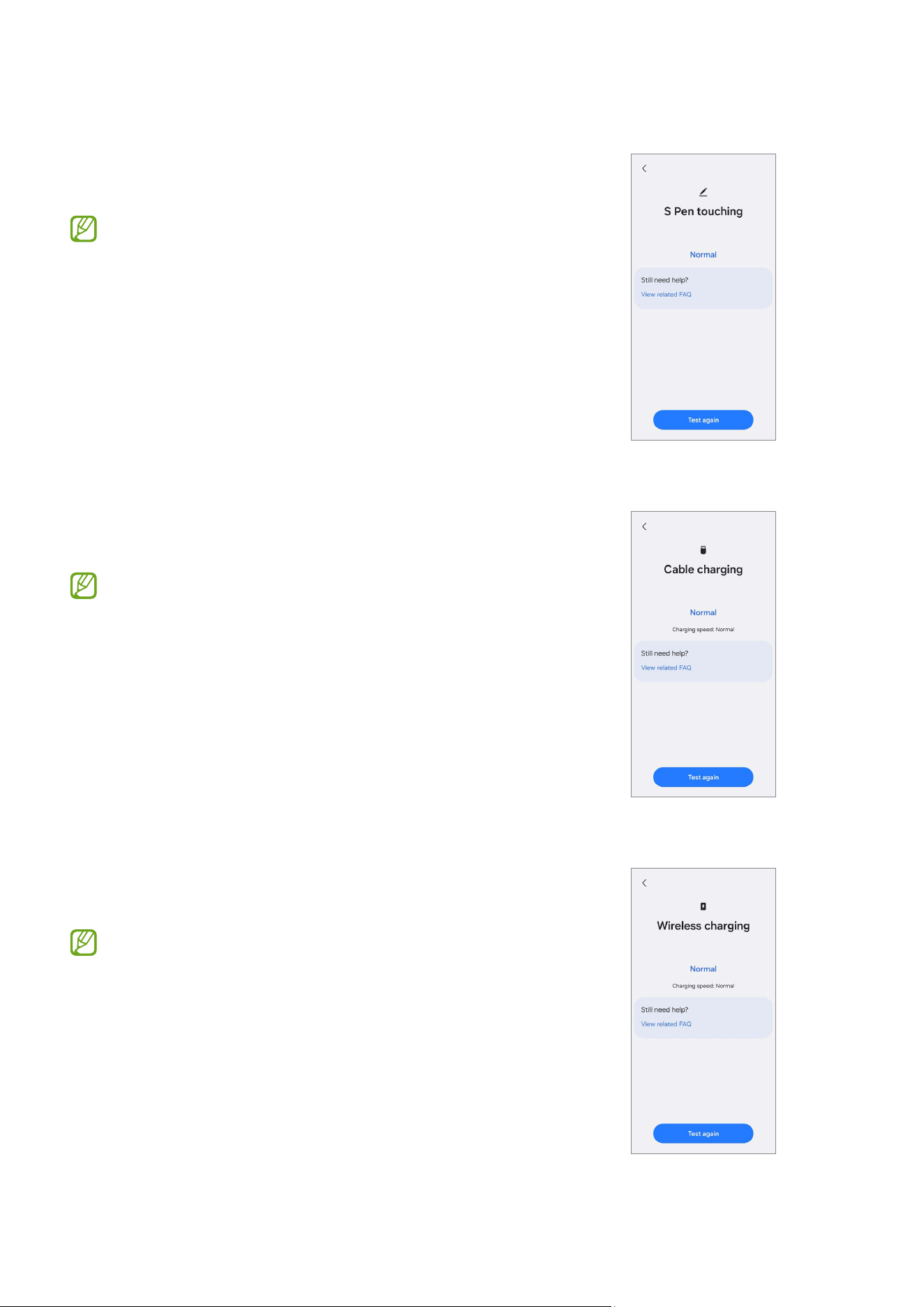
S Pen touching
Check whether the S Pen is recognised in all areas of
the touch screen.
•
Make sure that the screen is clean to get
more accurate test results.
•
This test is only available for the S Pen
supported models.
Cable charging
Check whether the cable charging feature is working
normally.
Use only Samsung-approved chargers.
Wireless charging
Check whether the wireless charging feature is
working normally.
Use only Samsung-approved wireless chargers.
Quality Test
21
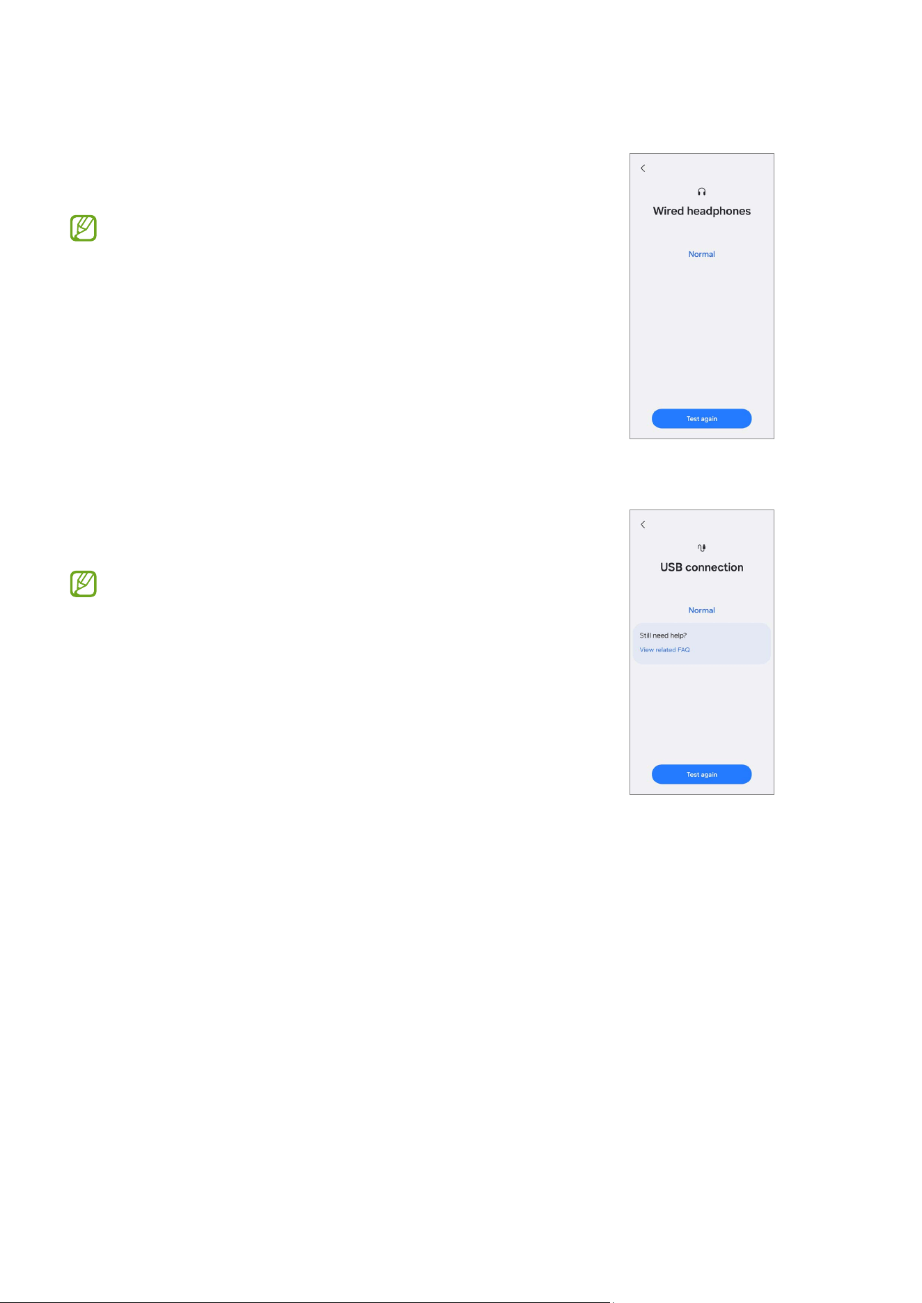
Wired headphones
Check whether the headphone jack recognises the
headphones normally.
To test this feature, you must connect
headphones.
USB connection
Check whether the multipurpose jack recognises the
USB cable normally.
To test this feature, the USB cable must be
connected to a computer.
Calibrations
22
Calibrations
Calibrations
In order to guarantee the stable and correct performance of components or sensors, it is
required to conduct calibrations through the
Self Repair Assistant
app after repair.
If the calibration results show any malfunctions, visit a Samsung Service Centre for
further action. Any malfunctions caused by your repair may incur additional repair
charges.
•
The
Self Repair Assistant
app is subject to update without any prior notice.
•
In order to conduct the accurate calibrations after repair, visit a Samsung Service
Centre or website to buy calibration equipment if you do not have any.
Used Parts and Calibration Functions in Supported Models
The calibration functions are automatically conducted based on the selected parts.
Screen Battery Back Glass Charging Port Speaker
Optical
Fingerprint Cal.
Yes No No No No
Range Sensor
Cal.
Yes Yes Yes Yes Yes
Battery Cycle
Resets.
No Yes No No No
Touch Screen
Panel Cal.
Yes No No No No
Speaker Cal. No No No No Yes
Under-display
Camera Cal.
Yes No No No No
Digital Hall
Sensor Cal.
Yes No No No No
Calibrations
23
•
Depending on the model, the screen module may include batteries. So when
the screen module is replaced, the battery also has to be selected and a battery
cycle reset must be performed.
•
In the Fold models, touch screen panel calibration is performed for both the
main and cover screens.
•
Digital hall sensor calibration is only for the Fold and Flip models and
under-display camera calibration is only for the Fold models.
Using the Self Repair Assistant App
1 Download the
Self Repair Assistant
app from
Galaxy Store
.
For US devices, you need to install the APK file for the
Self Repair Assistant
app
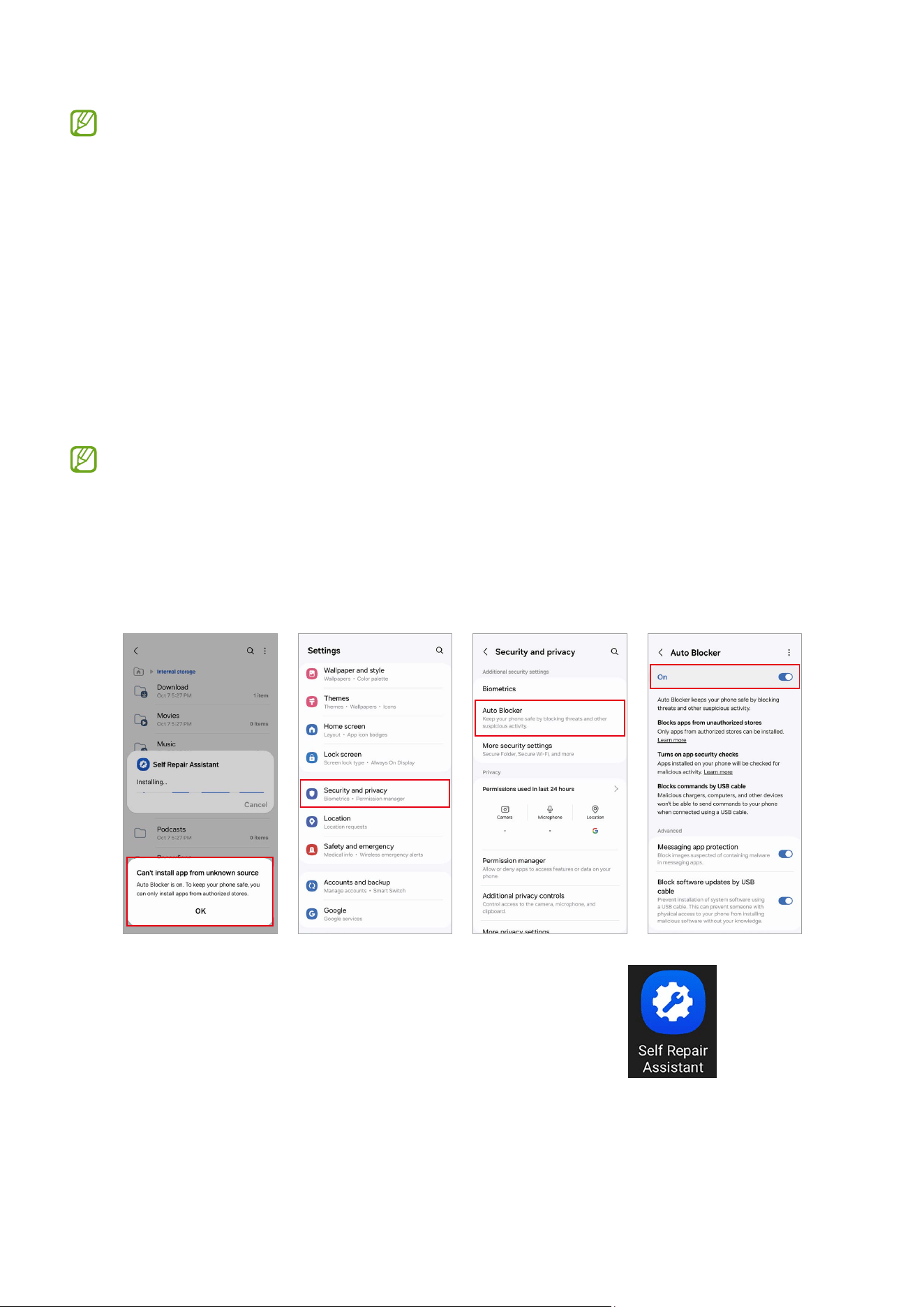
manually. However, if the
Auto Blocker
function which is provided from Android
OS 14 (U OS) is turned on, you cannot install any APK files manually through the
My
Files
app. In this case, launch the
Settings
app, tap
Security and privacy
→
Auto
Blocker
, and then tap the switch to turn it off to install the
Self Repair Assistant
app.
2 Launch the
Self Repair Assistant
app.
Calibrations
24
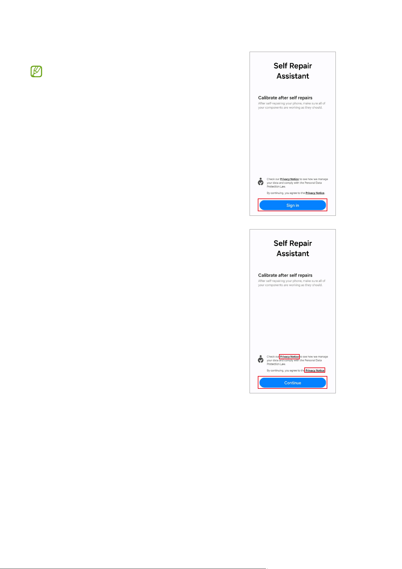
3 Read Privacy Notice and tap
Continue
.
•
If you are not signed in to your
Samsung account, a button will appear
to sign in.
•
If you select the link to read the full
Privacy Notice, you will be directed to
our site.
Calibrations
25
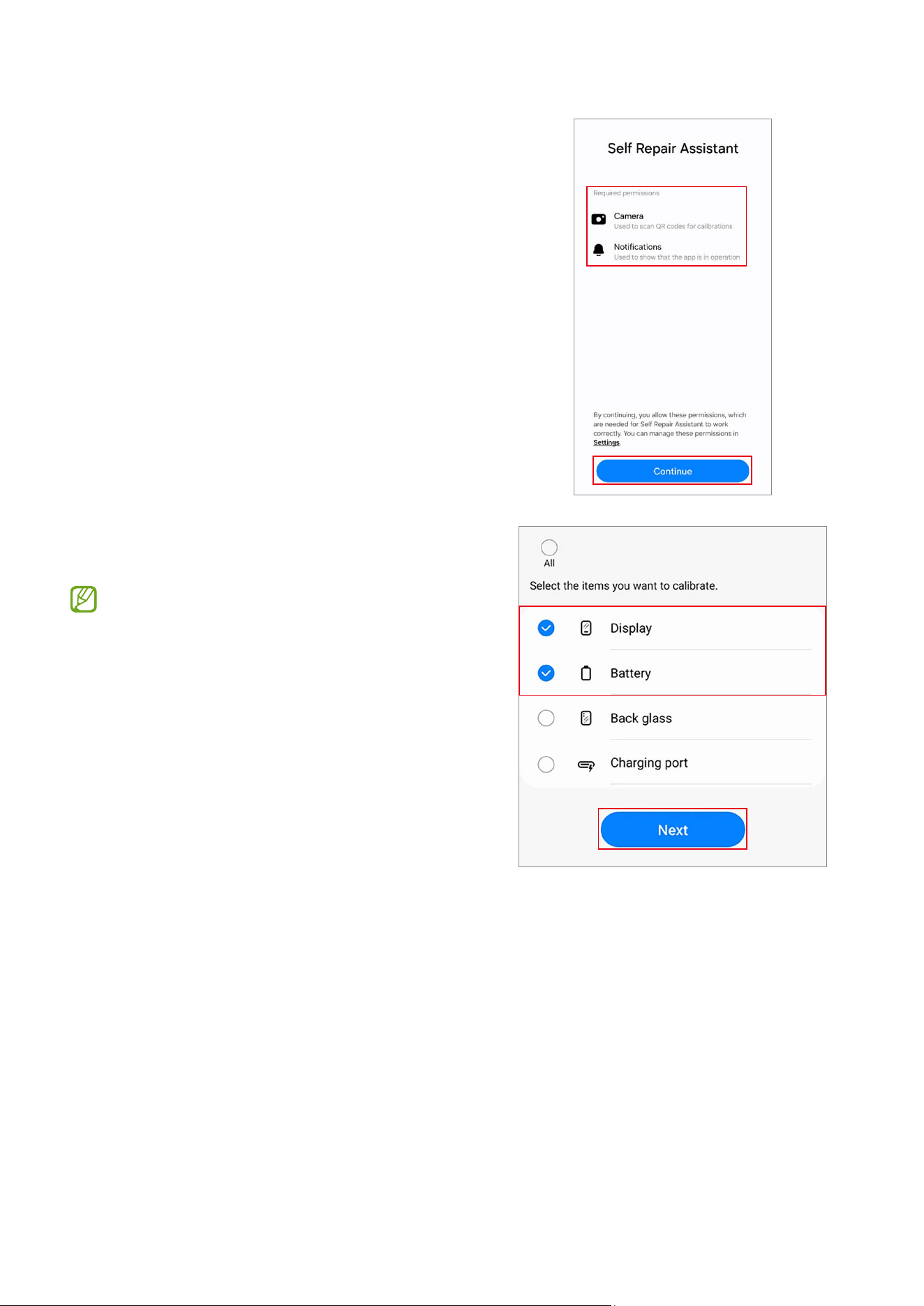
4 Check permissions and tap
Continue
.
5 Select the part that you have replaced and
tap
Next
.
•
The required calibrations will be
conducted automatically.
•
If the device does not have certain
components or sensors associated
with the part that has been replaced,
relative calibration will be skipped
automatically.
Calibrations
26
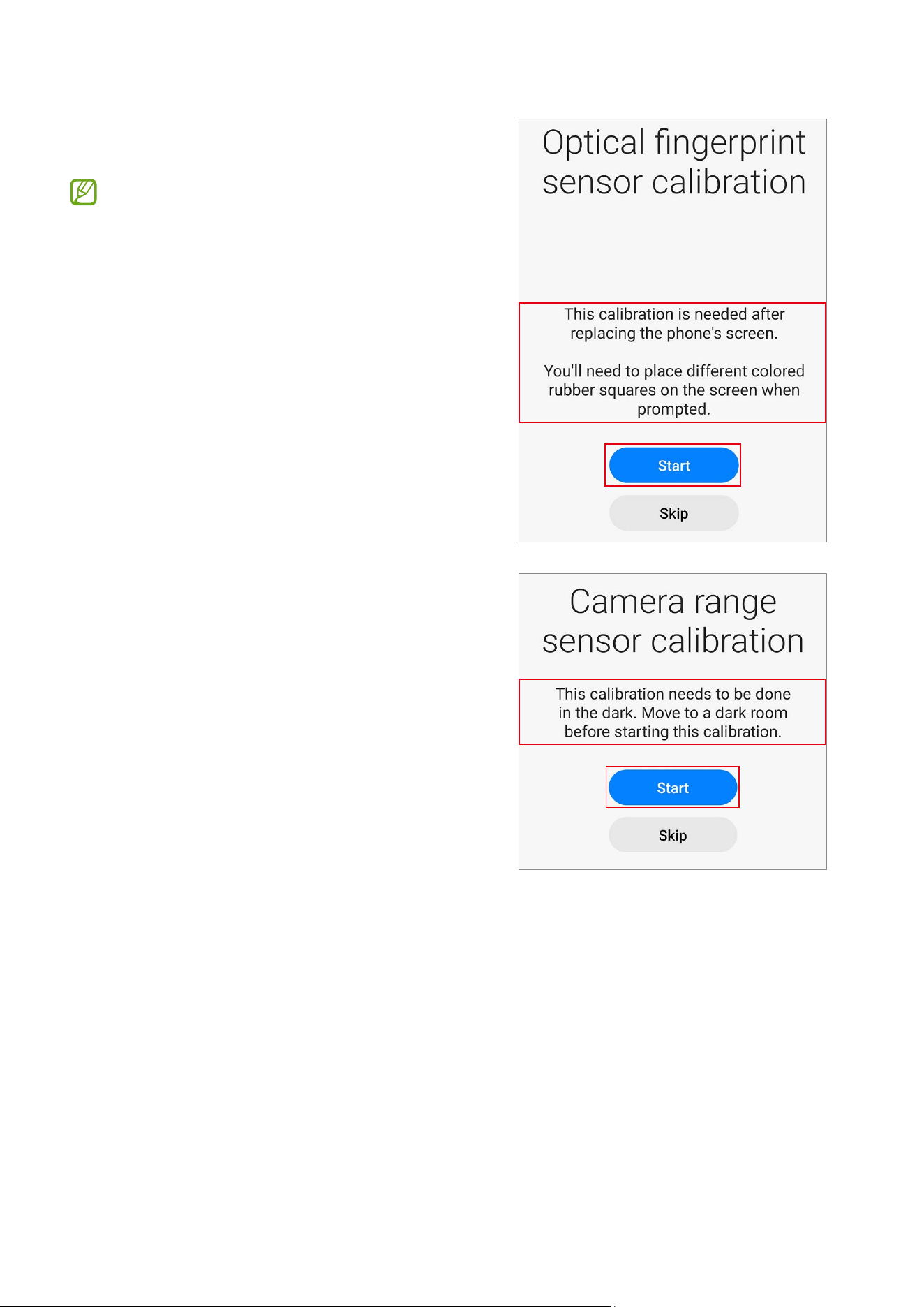
6 Read the on-screen instructions and tap
Start
.
Refer to Optical Fingerprint Sensor
Calibration, Resetting the Battery Cycle
Count, Range Sensor Calibration, Touch
Screen Panel Calibration, Speaker
Calibration, Under-display Camera
Calibration (Fold Models Only), and
Digital Hall Sensor Calibration (Fold and
Flip Models Only) for more information.
Calibrations
27
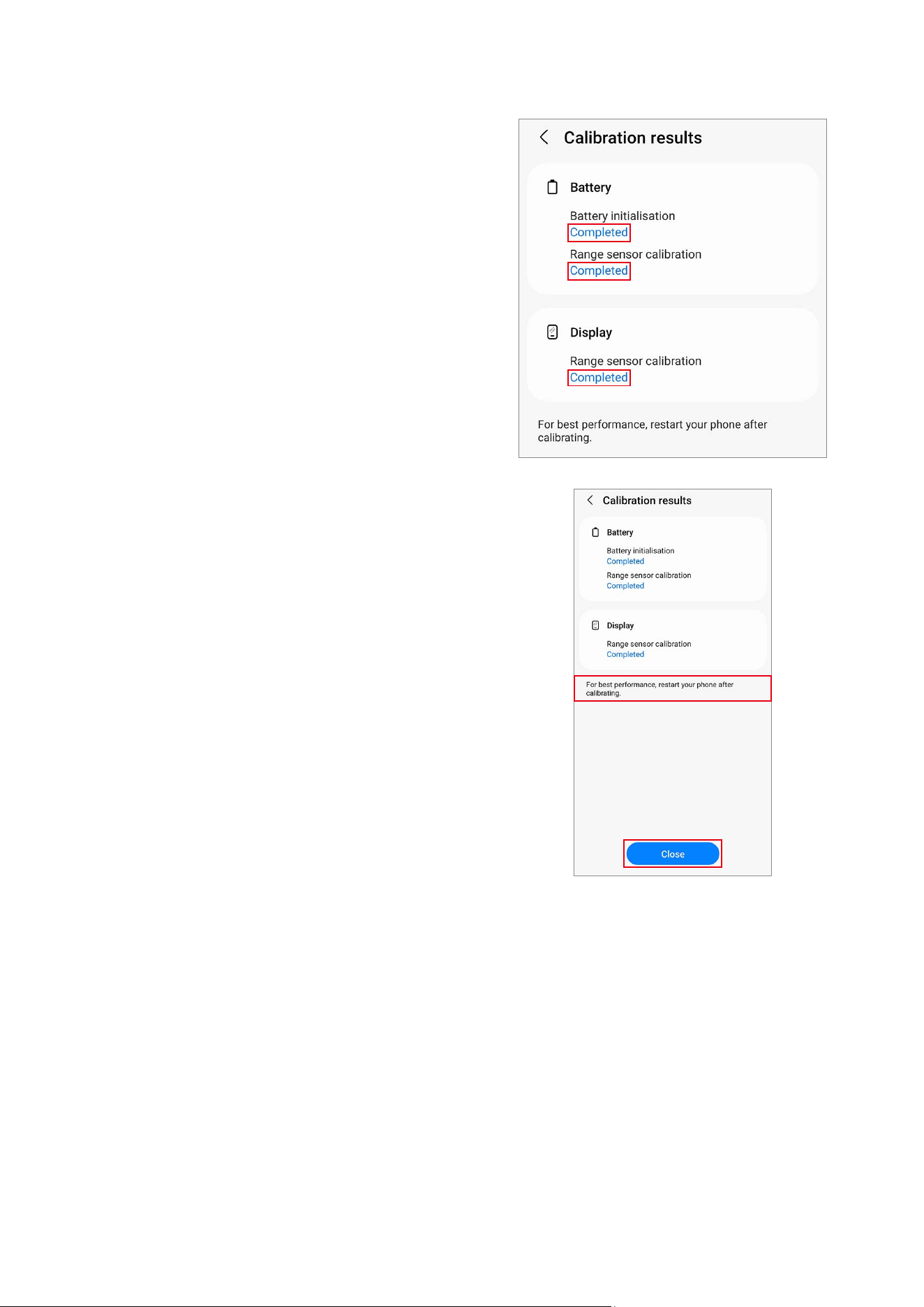
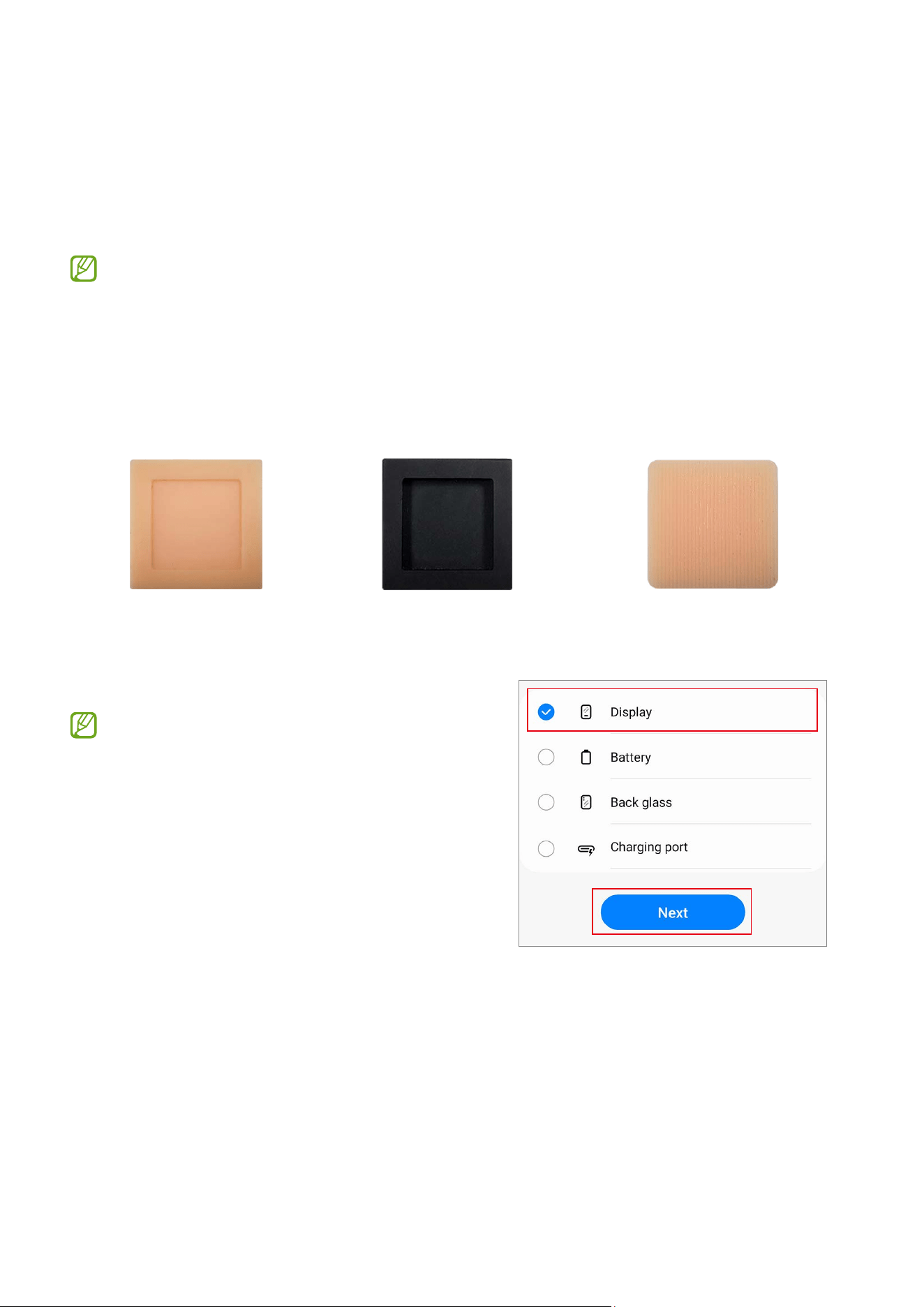
7 Check the results of each calibration item.
•
Completed
: Calibration was done
normally.
•
Failed
: Calibration failed.
•
Skipped
: Calibration was skipped.
8 On the calibration results page, tap
Close
to close the app.
Restart your device to finish calibrating.
Calibrations
28
Optical Fingerprint Sensor Calibration
Whenever the screen is replaced, the optical fingerprint sensor must be calibrated to
guarantee optimised fingerprint sensor performance for devices that have it.
Optical fingerprint sensor calibration is available through the
Self Repair Assistant
app.
•
This feature may not be available depending on the model. The availability of
this feature can be automatically checked in the Self Repair Assistant app, so
please follow the guidance of the Self Repair Assistant app.
•
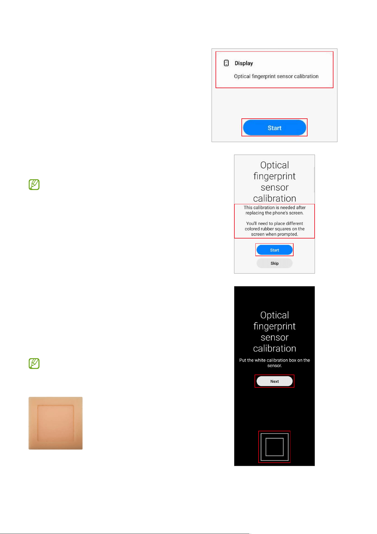
Three rubbers (the white calibration box, the black calibration box, and the 3D
fingerprint dummy rubber) are required to start this calibration.
White calibration box Black calibration box 3D fingerprint dummy rubber
1 Launch the
Self Repair Assistant
app.
2 Tap
Display
→
Next
.
•
The required calibration or test items
will be processed automatically.
•
If the device does not have certain
components or sensors associated
with the part that has been replaced,
relative calibration will be skipped
automatically.
Calibrations
29
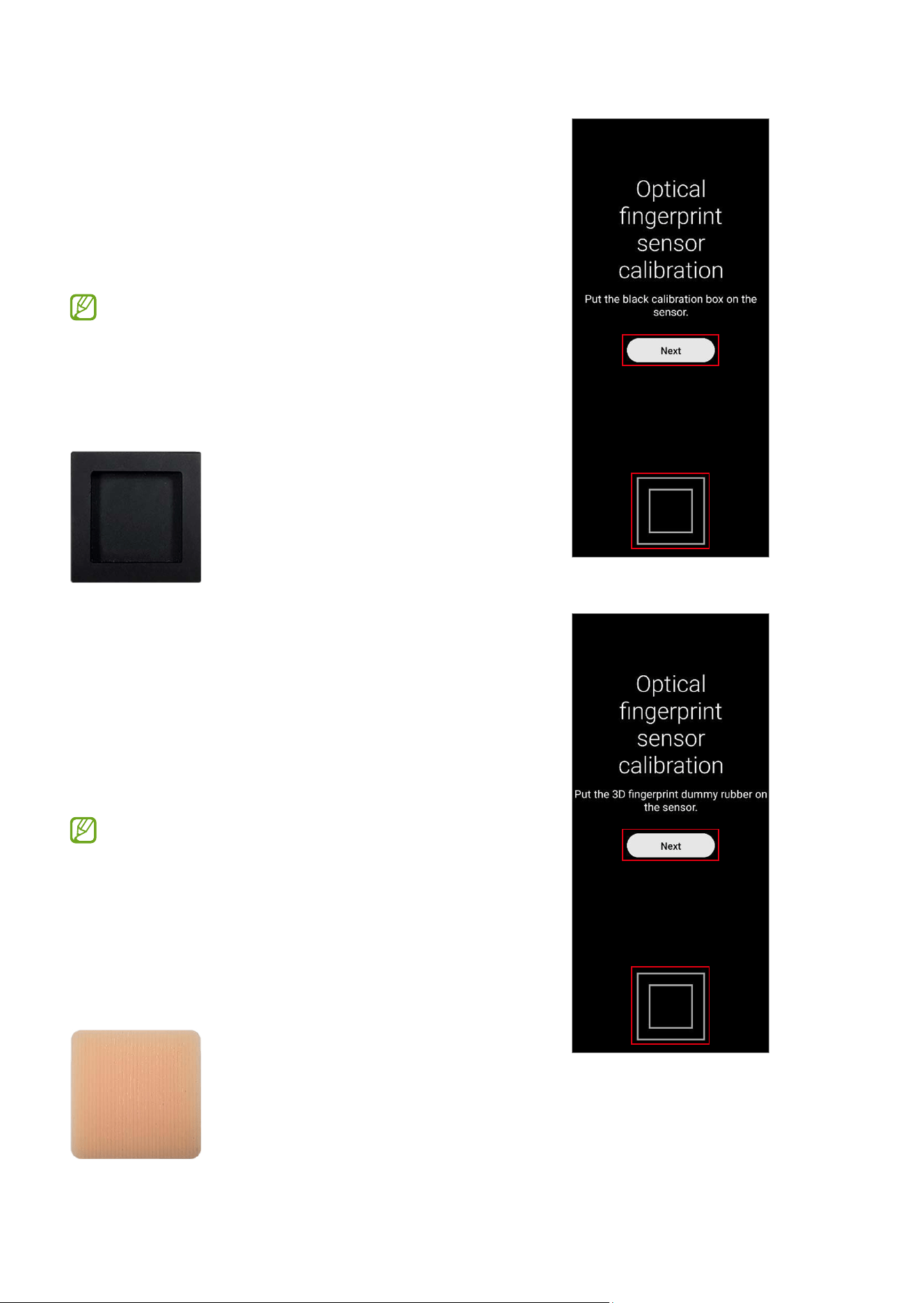
3 Check the part and calibration and then tap
Start
.
4 Read the on-screen instructions and tap
Start
.
The white calibration box must be
prepared before you start.
5 Put the white calibration box on the sensor
area (below the square side) and push the
rubber by applying force with your finger.
Tap
Next
and keep pushing the rubber
with your finger until you see the success
message.
The bottom side of the rubber that is
shaped like a square should be located
on the square guide line.
Calibrations
30
6 Put the black calibration box on the sensor
area (below the square side) and push the
rubber by applying force with your finger.
Tap
Next
and keep pushing the rubber
with your finger until you see the success
message.
•
The black calibration box must be
prepared before you start.
•
The bottom side of the rubber that is
shaped like a square should be located
on the square guide line.
7 Put the 3D fingerprint dummy rubber on
the sensor area (below the square side) and
push the rubber by applying force with your
finger.
Tap
Next
and keep pushing the rubber
with your finger until you see the success
message.
•
The 3D fingerprint dummy rubber
must be prepared before you start.
•
The bottom side of the rubber that is
shaped like a square should be located
on the square guide line. (Do not place
the pattern horizontally on the 3D
fingerprint dummy rubber.)
Calibrations
31
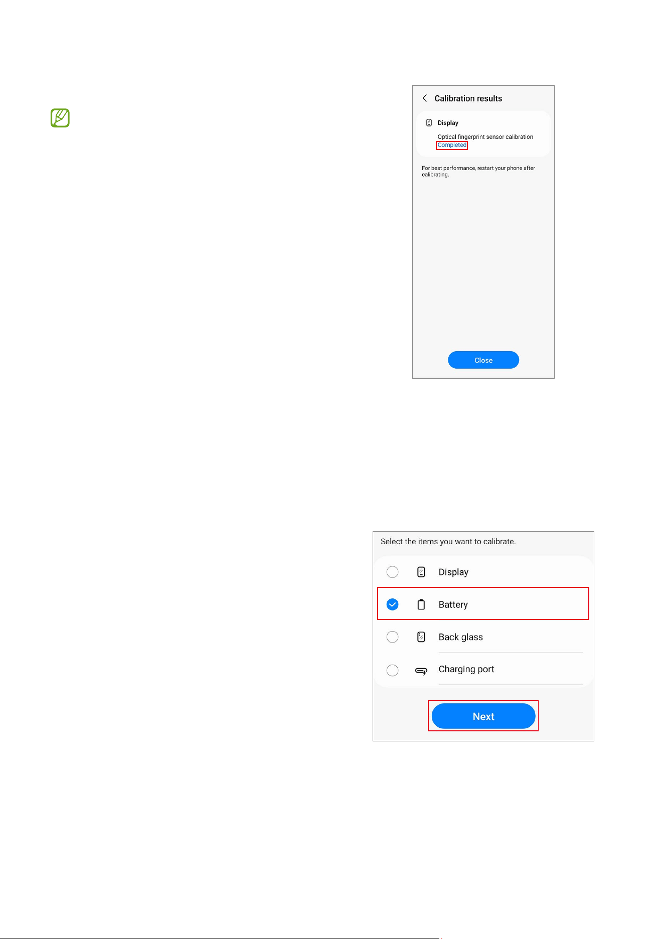
8 Check the result of the calibration.
Completed
appears only when the
calibration is successfully completed.
If
Completed
does not appear, try
calibrating again.
Resetting the Battery Cycle Count
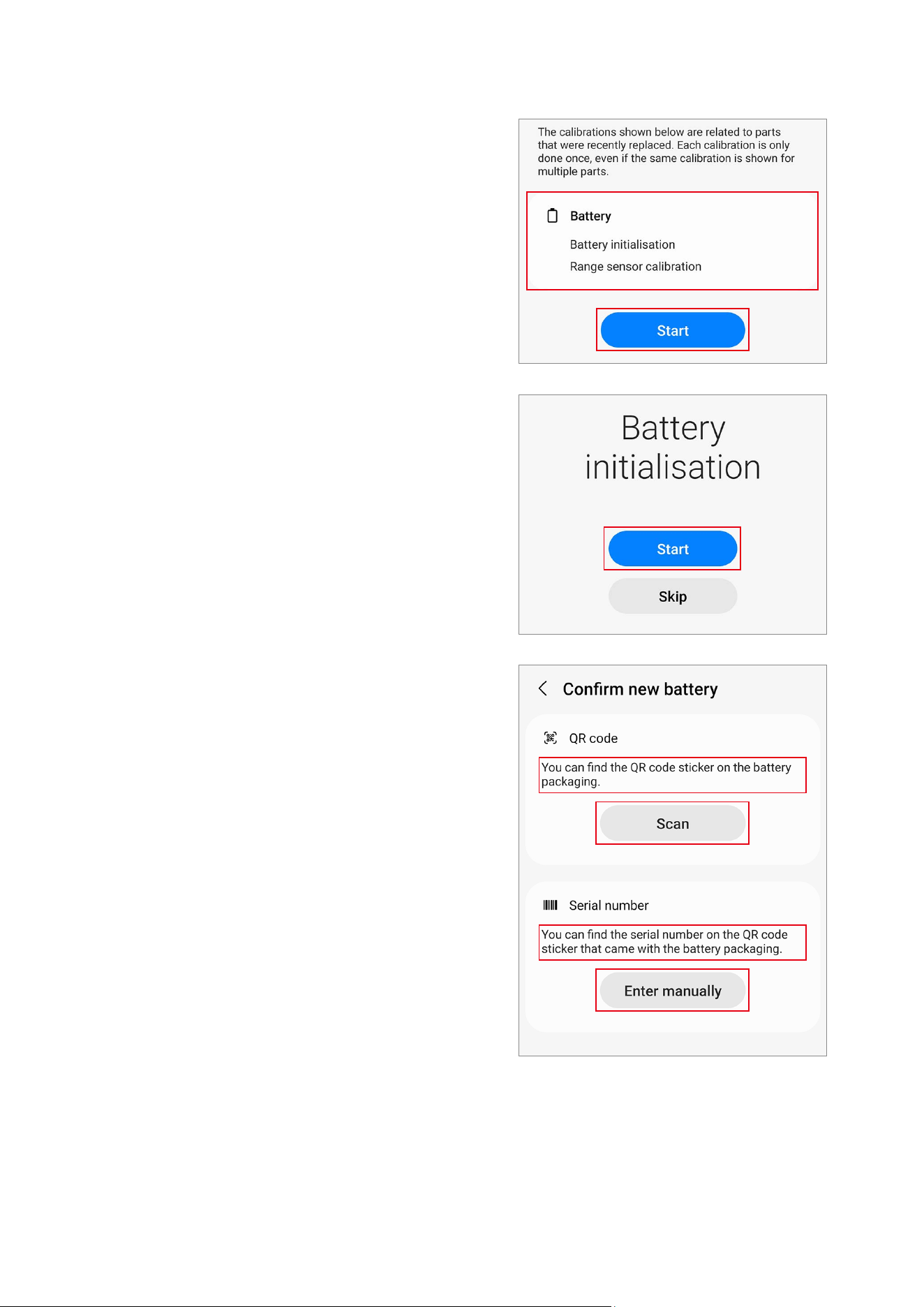
The battery cycle count should be reset whenever your device’s battery is replaced.
1 Launch the
Self Repair Assistant
app.
2 Select the part that you have replaced.
Tap
Battery
→
Next
.
Calibrations
32
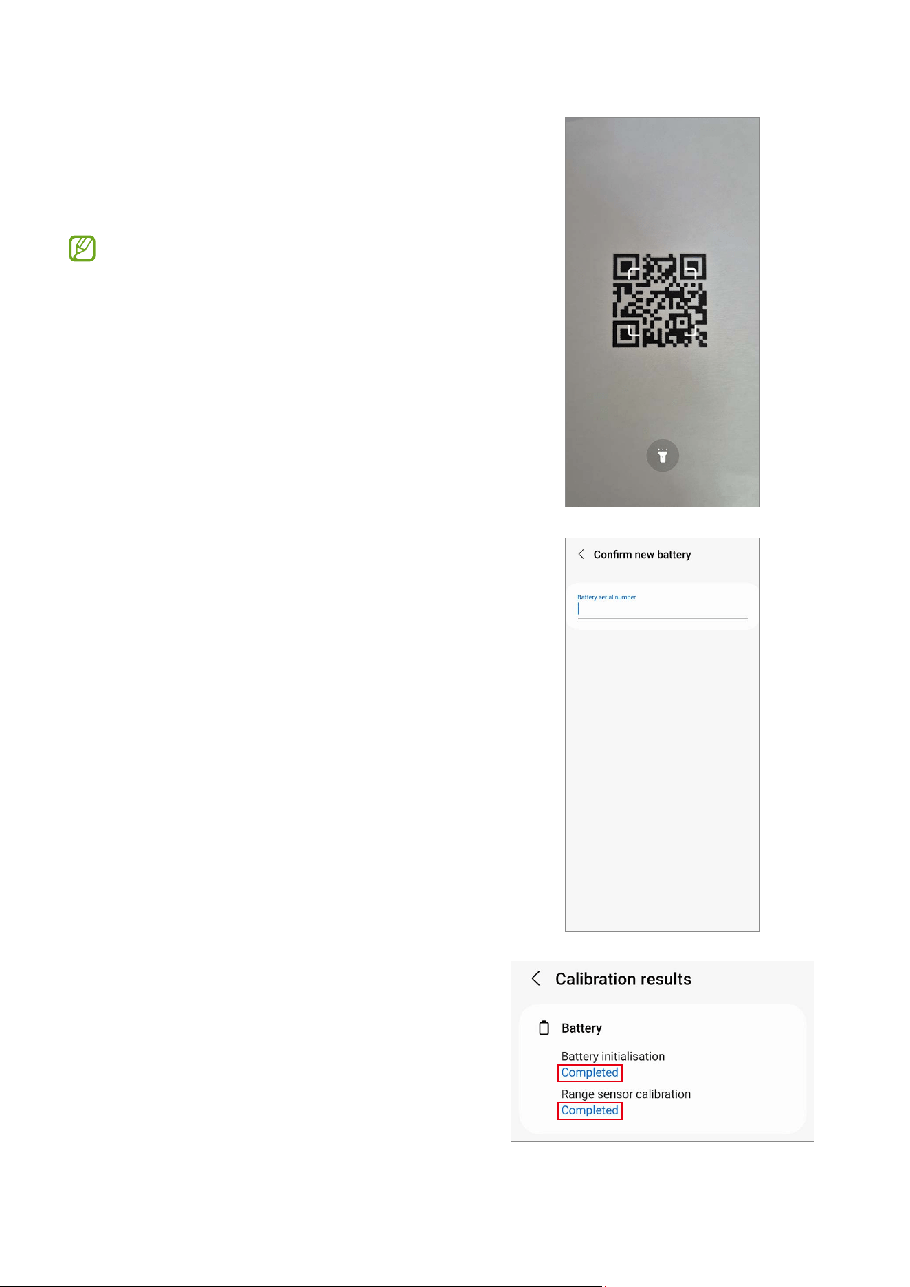
3 Check part and calibration and tap
Start
.
4 Tap
Start
.
5 Read the on-screen instructions and tap
Scan
to scan the QR code, or tap
Enter
manually
to enter the serial number
manually.
Calibrations
33
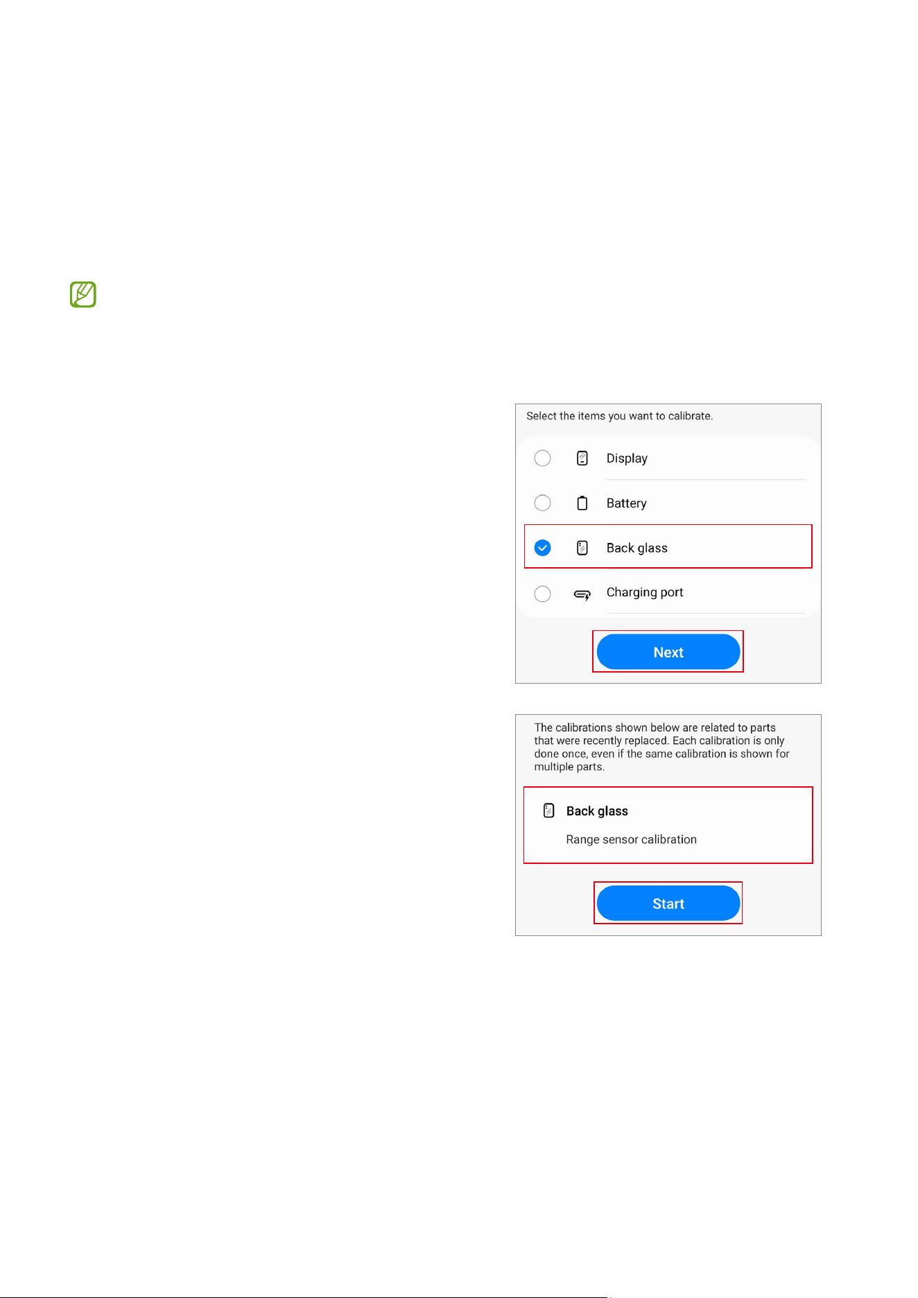
6 Scan the QR code or enter the serial
number that appears on the battery
package.
The reset will begin.
This image is an example of the QR code.
Make sure to scan the QR code on the
battery package.
7 Check the calibration results.
Calibrations
34
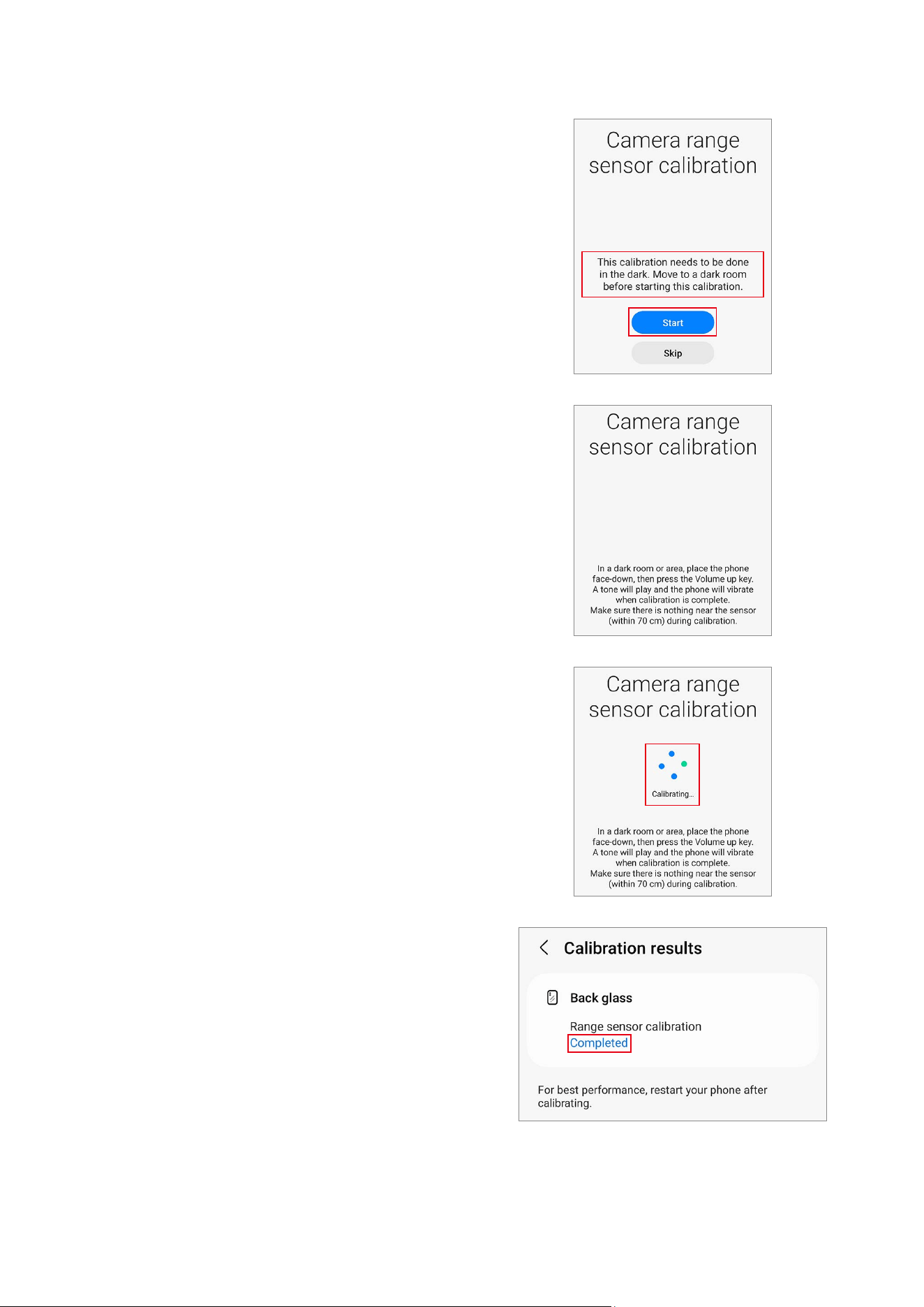
Range Sensor Calibration
When replacing screens, batteries, back glasses, or charging ports, range sensor
calibration is required to ensure the range sensors of devices equipped with them are
optimised.
Range sensor calibration is available through the
Self Repair Assistant
app.
Some content may differ from your device depending on the region, service
provider, model specifications, or device’s software.
1 Launch the
Self Repair Assistant
app.
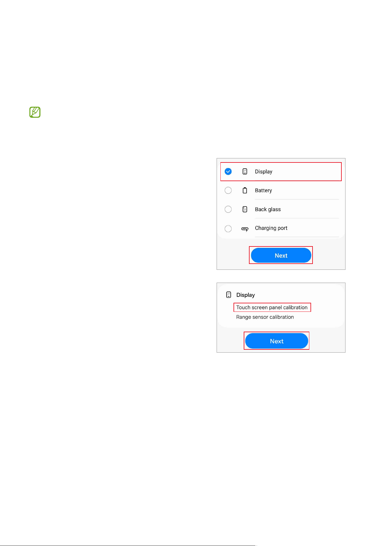
2 Select the part that you have replaced and
tap
Next
.
3 Check part and calibration and tap
Start
.
Calibrations
35
4 Read the on-screen instructions and tap
Start
.
5 In a dark room or area, place the phone
face-down, then press the Volume button.
6 The calibration will perform automatically.
A tone will play when calibration is
complete.
7 Check the calibration result.
Calibrations
36
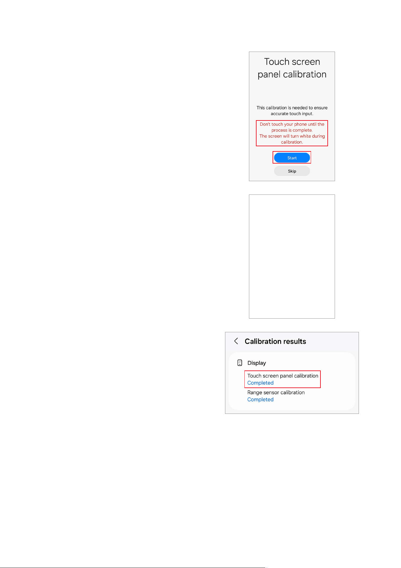
Touch Screen Panel Calibration
When replacing screens, touch screen panel calibration is required to ensure accurate
touch input.
Touch screen panel calibration is available through the
Self Repair Assistant
app.
In the Fold models, touch screen panel calibration is performed for both the main
and cover screens.
1 Launch the
Self Repair Assistant
app.
2 Select the part that you have replaced and
tap
Next
.
3 Check part and calibration and tap
Next
.
Calibrations
37
4 Read the on-screen instructions and tap
Start
.
5 The calibration will perform automatically
and the screen will turn white during
calibration.
6 Check the calibration result.
Calibrations
38
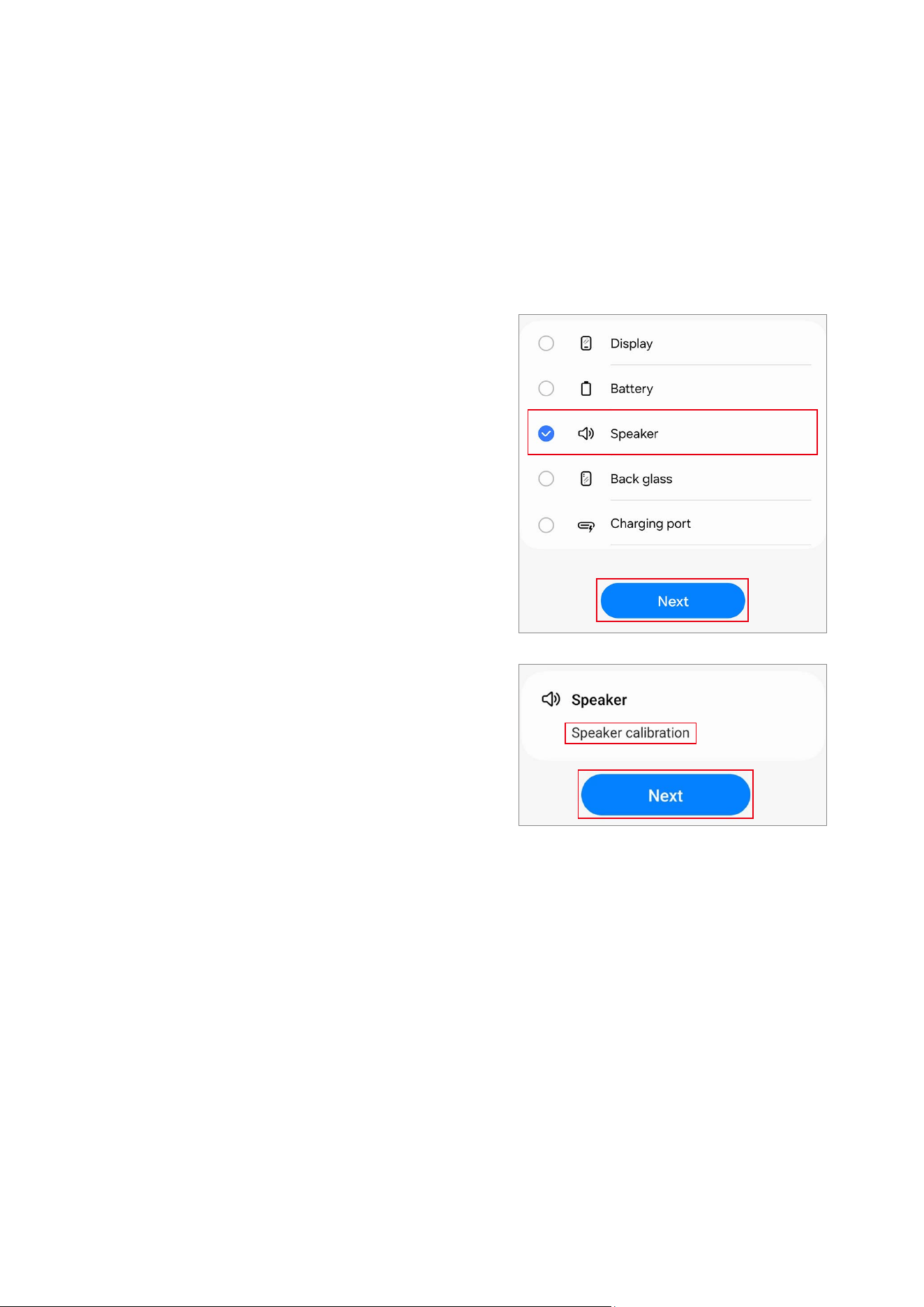
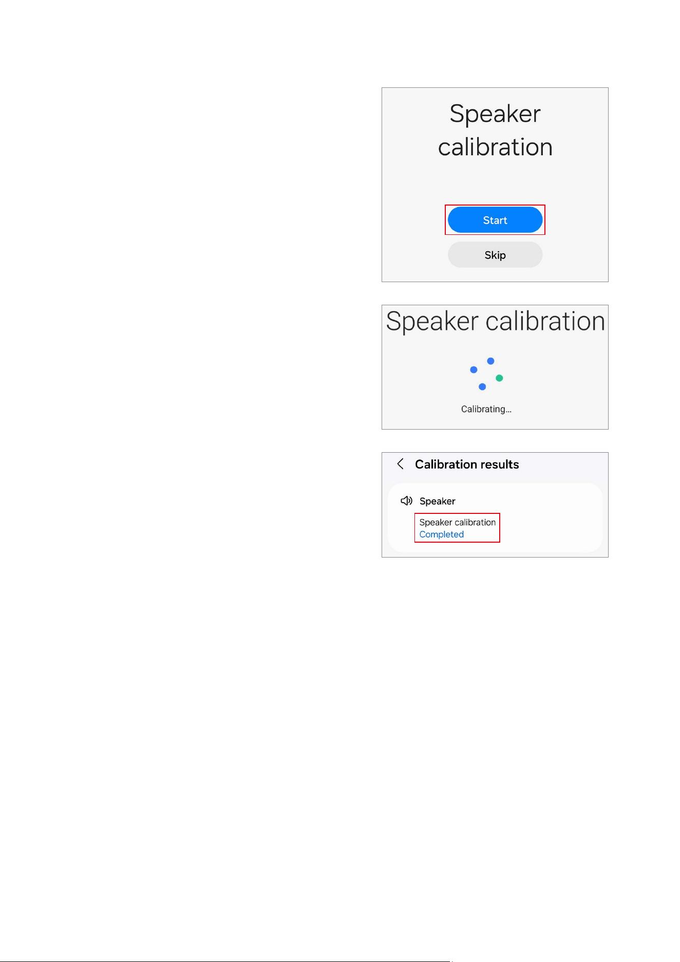
Speaker Calibration
When replacing speakers, the speaker must be calibrated to guarantee optimised
speaker performance for devices that have it.
Speaker calibration is available through the
Self Repair Assistant
app.
1 Launch the
Self Repair Assistant
app.
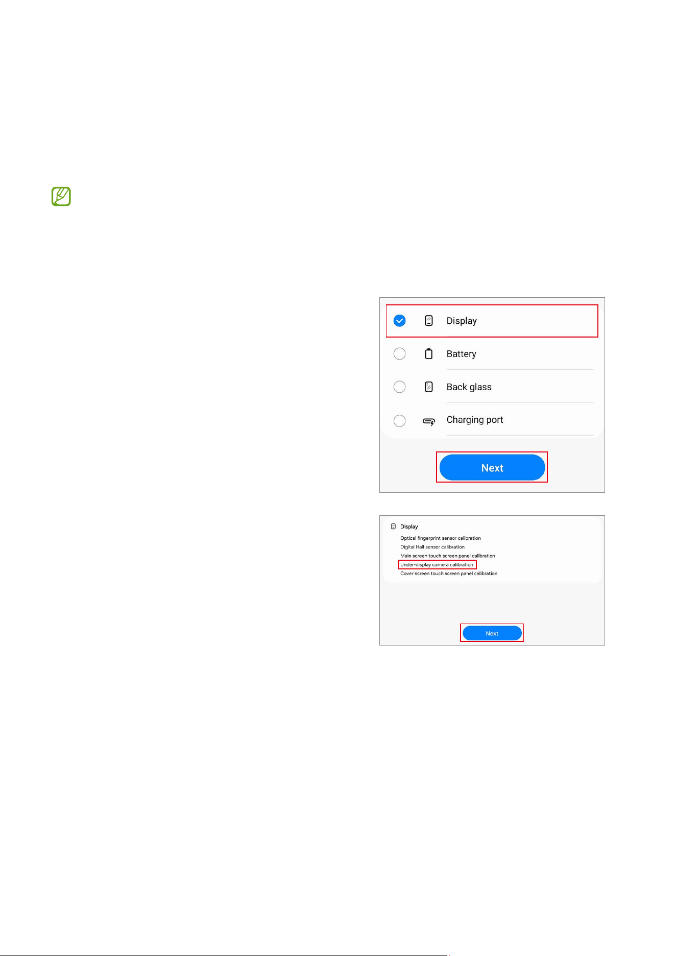
2 Select the part that you have replaced and
tap
Next
.
3 Check part and calibration and tap
Next
.
Calibrations
39
4 Tap
Start
.
5 The calibration will perform automatically.
6 Check the calibration result.
Calibrations
40
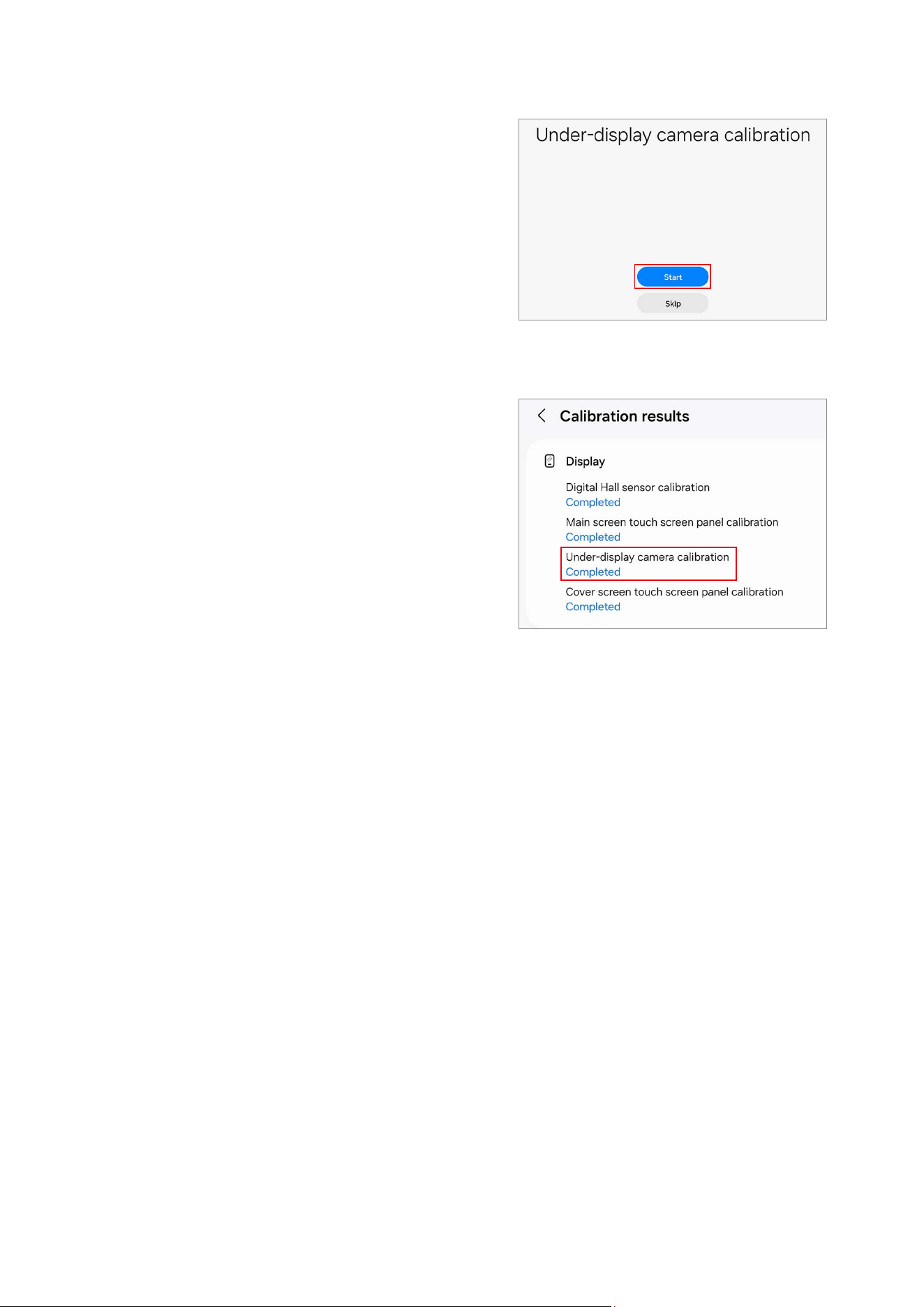
Under-display Camera Calibration (Fold Models Only)
Whenever the screen is replaced, the under-display camera must be calibrated to
guarantee optimised under-display camera performance for devices that have it.
Under-display camera calibration is available through the
Self Repair Assistant
app.
This feature may not be available depending on the model. The availability of this
feature can be automatically checked in the Self Repair Assistant app, so please
follow the guidance of the Self Repair Assistant app.
1 Launch the
Self Repair Assistant
app.
2 Select the part that you have replaced and
tap
Next
.
3 Check part and calibration and tap
Next
.
Calibrations
41
4 Tap
Start
.
5 The calibration will perform automatically.
6 Check the calibration result.

Calibrations
42
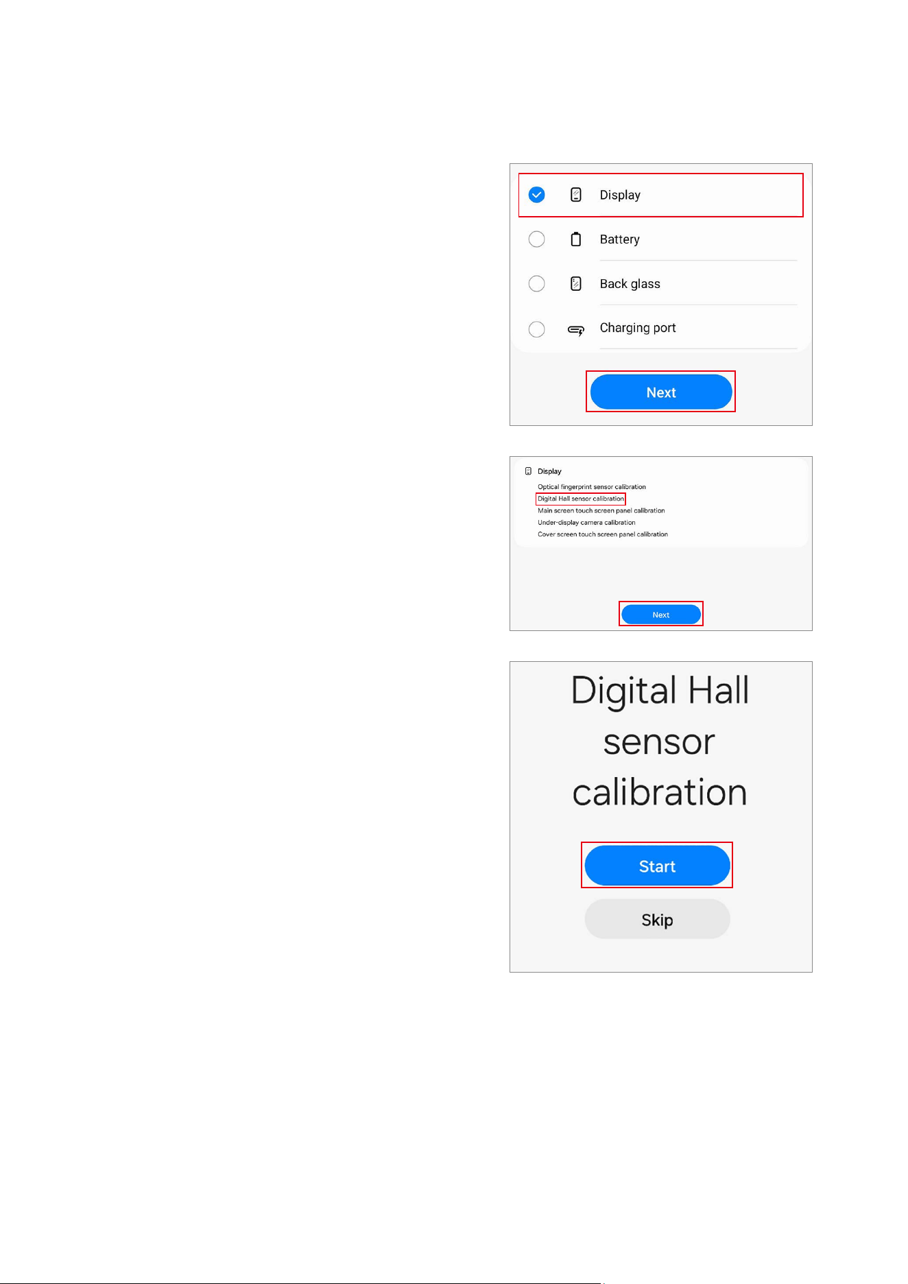
Digital Hall Sensor Calibration (Fold and Flip Models Only)
Whenever the screen is replaced, the digital hall sensor must be calibrated to guarantee
optimised digital hall sensor performance for devices that have it.
Digital hall sensor calibration is available through the
Self Repair Assistant
app.
•
This feature may not be available depending on the model. The availability of
this feature can be automatically checked in the Self Repair Assistant app, so
please follow the guidance of the Self Repair Assistant app.
•
For Fold models: If the main screen does not turn on after being replaced (the
main screen is off and the cover screen is on when the device is unfolded),
follow the steps below to perform digital hall sensor calibration. The boot
screen (the screen where the Samsung and carrier logos appear) will appear
normally and then turn off, so it is not a hardware failure.
1) Fold the device and launch the
Self Repair Assistant
app on the cover
screen.
2) Move to the digital hall sensor calibration screen, unfold the device, and
then press the Volume Up button or the Volume Down button.
3) You will hear a vibration, and the calibration will be performed
automatically.
When calibration is complete, the main screen will turn on normally.
•
For Flip models: If the main screen does not turn on after being replaced (the
main screen is off and the cover screen is on when the device is unfolded),
follow the steps below to force the main screen to turn on and perform digital
hall sensor calibration. The boot screen (the screen where the Samsung and
carrier logos appear) will appear normally and then turn off, so it is not a
hardware failure.
1) Connect the USB cable to the device, and connect the other end of the USB
cable to the USB power adapter or your computer.
2) While pressing and holding the Side button, press the Volume Up button
once and the Volume Down button twice.
3) When the main screen turns on, perform digital hall sensor calibration.
Calibrations
43
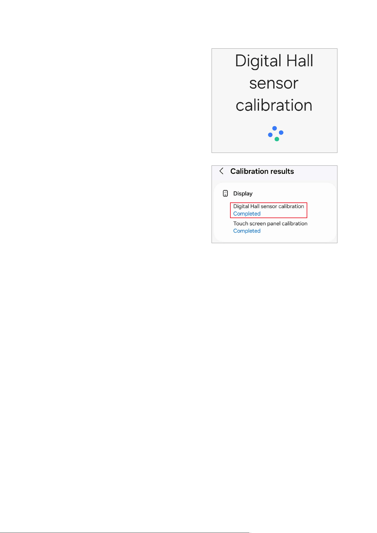
1 Launch the
Self Repair Assistant
app.
2 Select the part that you have replaced and
tap
Next
.
3 Check part and calibration and tap
Next
.
4 Tap
Start
.
Calibrations
44
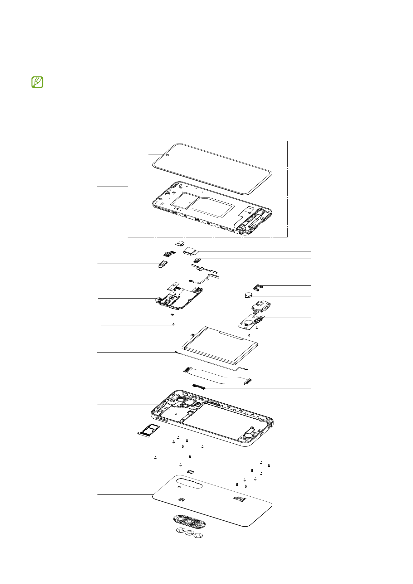
5 The calibration will perform automatically.
6 Check the calibration result.
Exploded View and Parts List
45
Exploded View and Parts List
The product’s composition may vary depending on the country, region, or carrier.
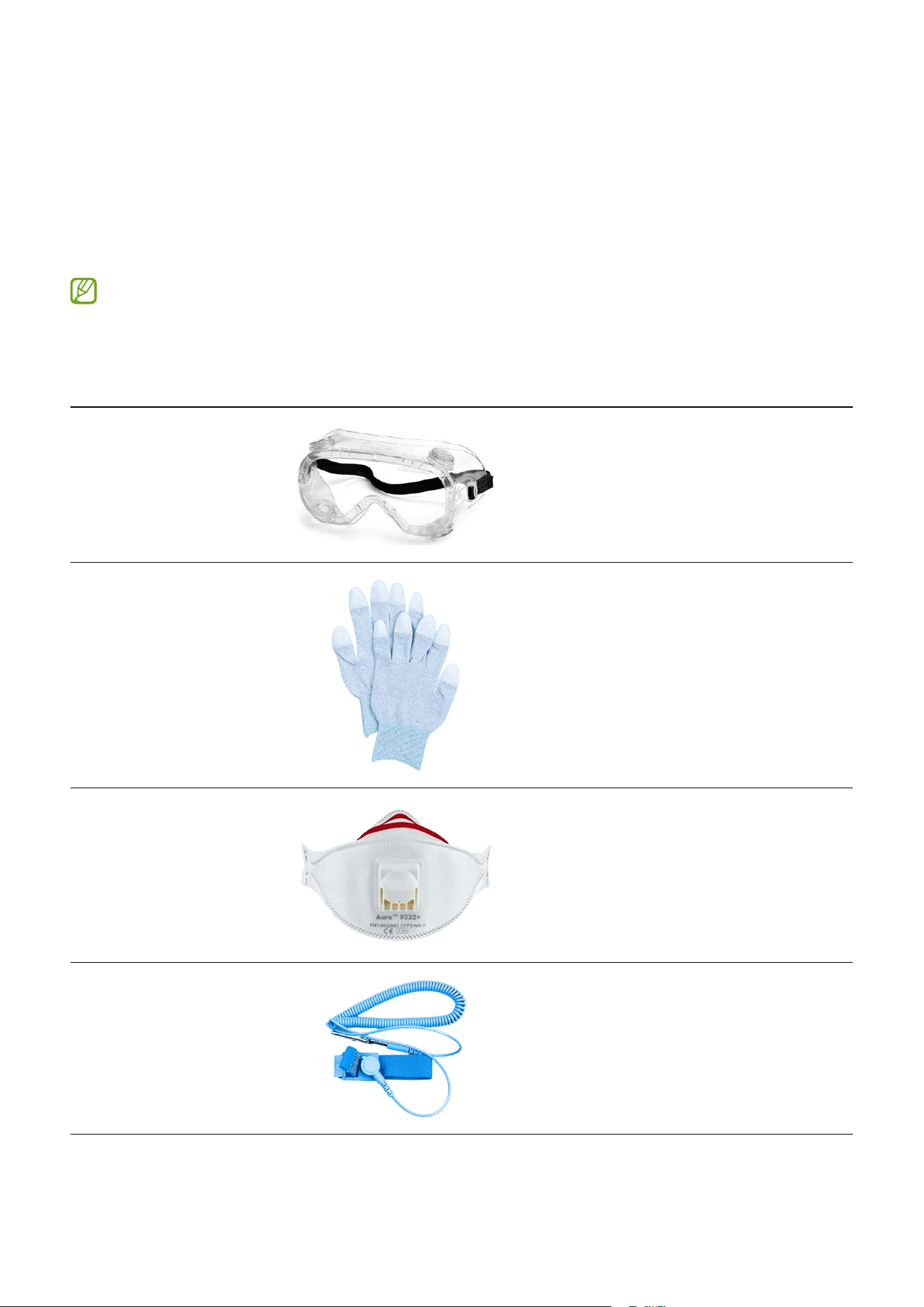
Exploded View
QCR532
QCR637
QBR01
QCA14
QCAU01
QCA13
QCA02
QAR01
QMO11
QRU01
QSP01
QRE01
QVO01
QSM01
QMP01
QFR01
QBA01
QME01
QBC01
QIF01
QFP01
QCB11
QUB01

Exploded View and Parts List
46
Parts List
Number Name
QCR532 Screw 3532
QCR637 Screw 3637
QBR01 Fingerprint Recognition Sensor Connector Cover
QCA14 Rear Camera (Macro)
QCAU01 Rear Camera (Ultra Wide)
QCA02 Front Camera
QCA13 Rear Camera (Wide)
QAR01 Top Speaker
QCR637 Screw 3637
QMO11 Vibrator Motor
QCB11 Antenna Flex Cable (Blue)
QRU01 Charging Port Rubber
QIF01 Charging Port
QSP01 Bottom Speaker
QRE01 Rear Bracket
QVO01 Volume Button
QSM01 SIM Card Tray
QMP01 Main Board (PBA)
QFR01 Screen Module
QBA01 Battery
QME01 Main Flex Cable (Main Board to Charging Port)
QBC01 Back Cover
QFP01 Side Button (Fingerprint Recognition Sensor)
QUB01 Screen
Disassembly and Assembly
47
Disassembly and Assembly
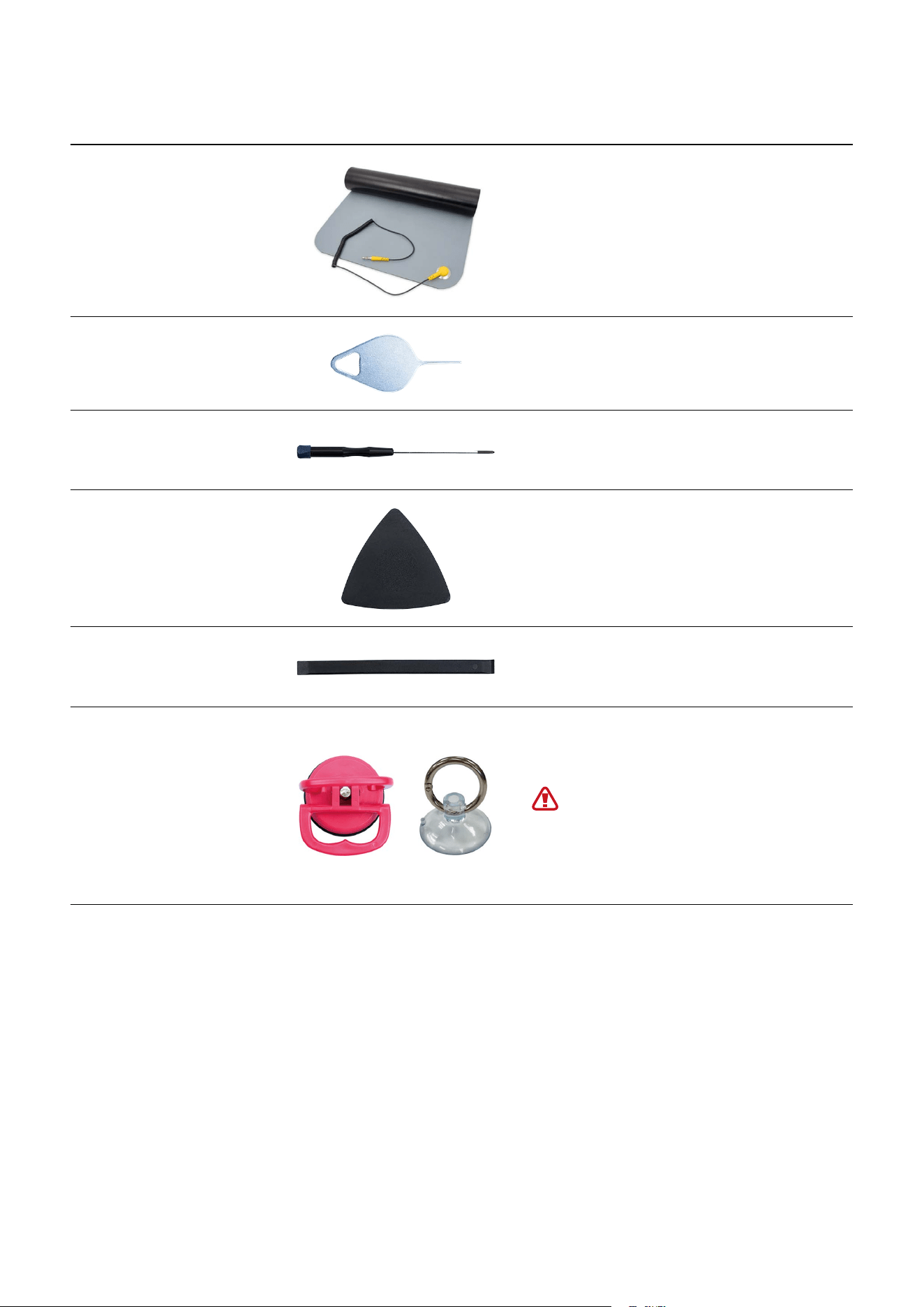
Tools for Disassembly and Assembly
When repairing devices, you absolutely must wear protective equipment for your safety.
Availability of rental services for toolkits with a complete set of tools for self
repair service may vary depending on the country and is currently available only in
limited countries.
Tool & Part Code Image Description
Safety Goggles
Prevents accidents during repair
(protective equipment)
Safety Gloves (ESD
safe, cut-resistant)
Prevents accidents during repair
(protective equipment)
Safety Mask
Prevents accidents during repair
(protective equipment)
Anti-static Wrist
Strap
Prevents electrostatic damage
(recommended)
Disassembly and Assembly
48
Tool & Part Code Image Description
ESD Safe Mat
Prevents electrostatic damage
(recommended)
Ejection Pin
Pin for ejecting the SIM card tray
Cross-head
Screwdriver
Tool for screwing in cross-head
screws
Opening Pick
Tool for disassembling the back
cover, screen, and other parts
Opening Tool
Tool for disassembling the
connector and other parts
Suction Cup
Tool for disassembling the back
cover, screen, and other parts
For separable handle suction
cups, be careful not to injure
yourself as the handle can be
parted during use.
Disassembly and Assembly
49
Tool & Part Code Image Description
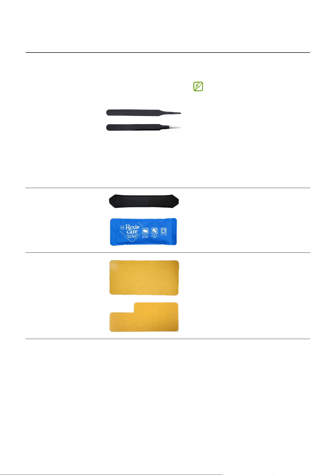
ESD Safe Tweezers
and Round Tip
Metal Tweezers
Tool for handling connectors,
cables, and other parts
•
Because it is possible
to damage parts or
components when using
sharp tweezers, use
tweezers made with plastic
or rubber material.
•
When removing a Vibrator
Motor, it is required to
use the round tip metal
tweezers.
Heating Bag
Tool for disassembling the back
cover, screen, and other parts
Acrylic Protective
Cover for Broken
Glass
For screen
For back glass
Prevents injuries and scattering
caused by broken glass
Disassembly and Assembly
50
Tool & Part Code Image Description
Bottom Press Tray
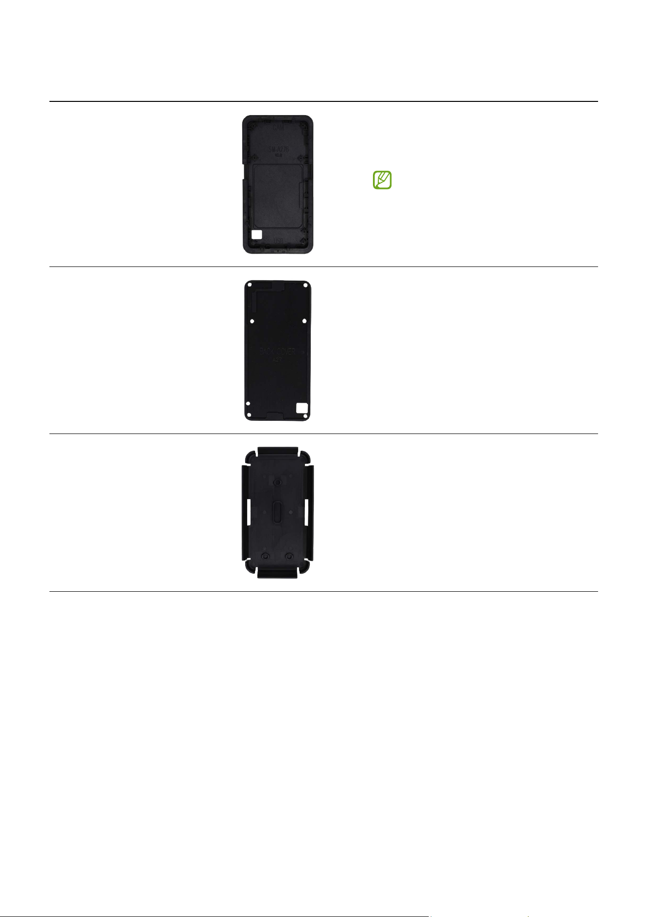
Tool for pressing the back cover,
screen or battery
You can choose the one side
of the bottom press tray
depending on the back cover,
screen, or battery.
Bottom Rubber Pad
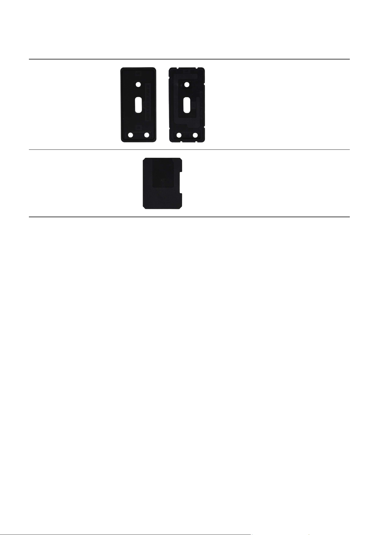
Tool to press the back cover by
placing into the bottom press tray
Top Press Tray
Tool to press the back cover, screen
or battery by covering the bottom
press tray
Disassembly and Assembly
51
Tool & Part Code Image Description
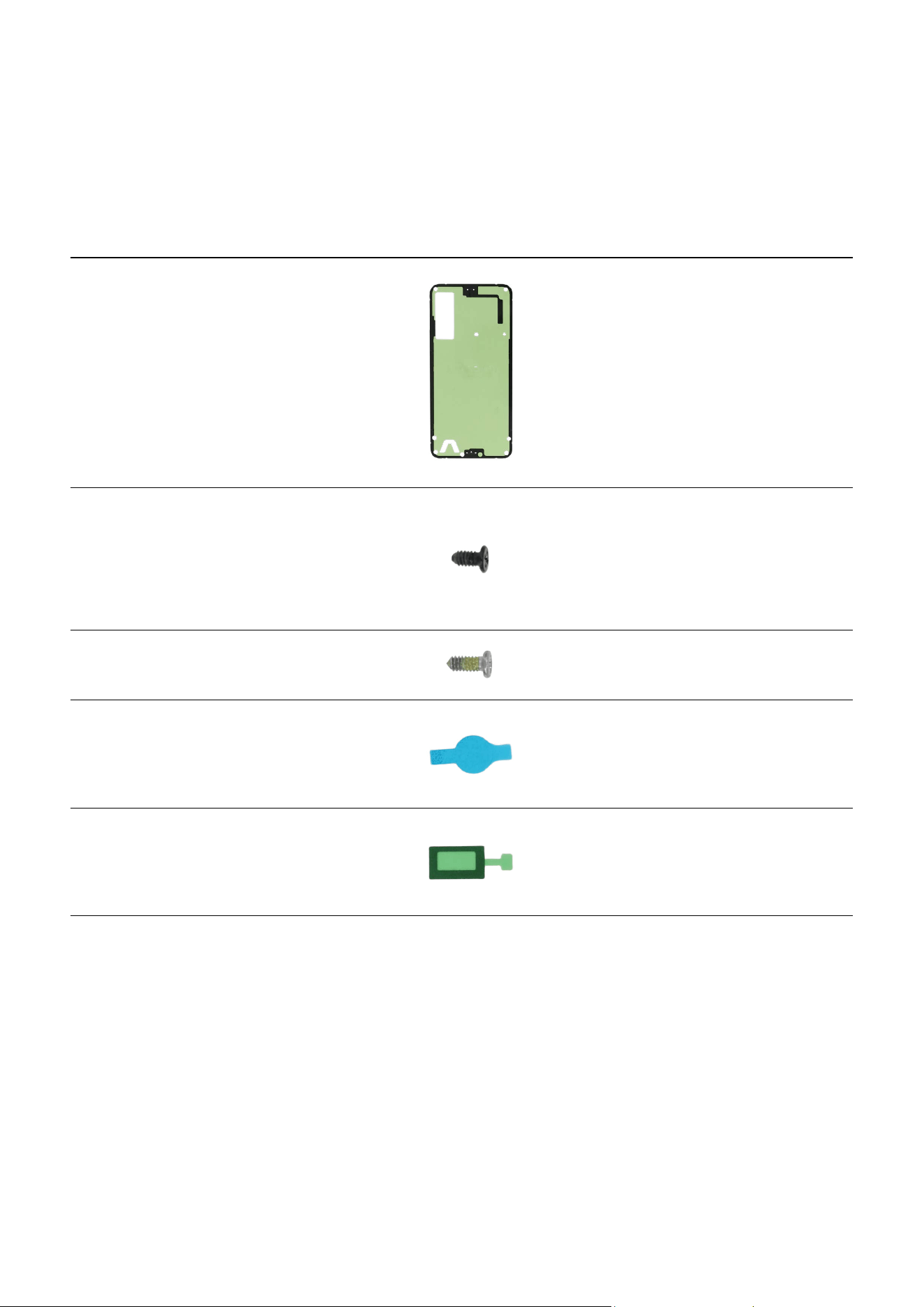
Top Rubber Pad
Tool to press the back cover, screen
or battery by placing into the top
press tray
Battery Rubber Pad
Tool to press the battery by placing
into the bottom press tray.
Disassembly and Assembly
52
Fasteners (Adhesives and Materials) for Assembly
The fasteners composition may vary depending on the repair parts, country, region, or
carrier.
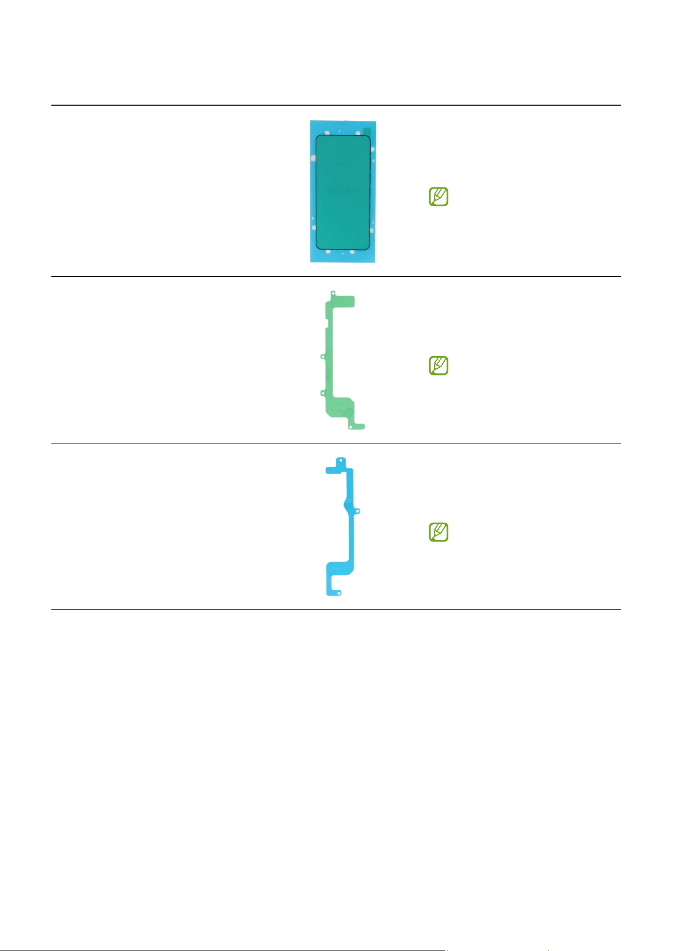
Item Quantity Image Description
Back Cover
Adhesive tape
1
Double sided adhesive tape
for attaching the back cover
to metal frame
Screw 3637 3
Screw for the main board
(1 ea)
Screws for the charging port
(2 ea)
Screw 3532 16
Screws for the rear
Vibrator Motor
Adhesive Tape
1
Double sided adhesive tape
for attaching the vibrator
motor to screen module
Top Speaker
Adhesive Tape
1
Double sided adhesive tape
for attaching the speaker to
screen module
Disassembly and Assembly
53
Item Quantity Image Description
Screen Side
Adhesive tape
1
Double sided adhesive tape
for attaching the sides of
screen to metal frame
This tape is only
available when
the screen itself is
repaired.
Screen Left
Adhesive tape
1
Double sided adhesive tape
for attaching the left of
screen to metal frame
This tape is only
available when
the screen itself is
repaired.
Screen Right
Adhesive tape
1
Double sided adhesive tape
for attaching the right of
screen to metal frame
This tape is only
available when
the screen itself is
repaired.

Disassembly and Assembly
54
Disassembly and Reassembly for replacement
•
The product’s composition may vary depending on the country, region, or
carrier.
•
Repairable parts may vary depending on the country or region.
Before disassembling:
•
Unplug and turn off device before disassembling.
•
Wear an anti-static wrist strap and connect it to the grounded ESD safe mat.
Before reassembling:
•
Remove the adhesive tape residues perfectly.
•
Prepare all existing screws of this device and adhesive tapes.
•
Wear an anti-static wrist strap and connect it to the grounded ESD safe mat.
•
Leaving screws inside the device may damage internal components, such as the
battery. When assembling, be extra careful not to leave any unassembled screws
inside the device.
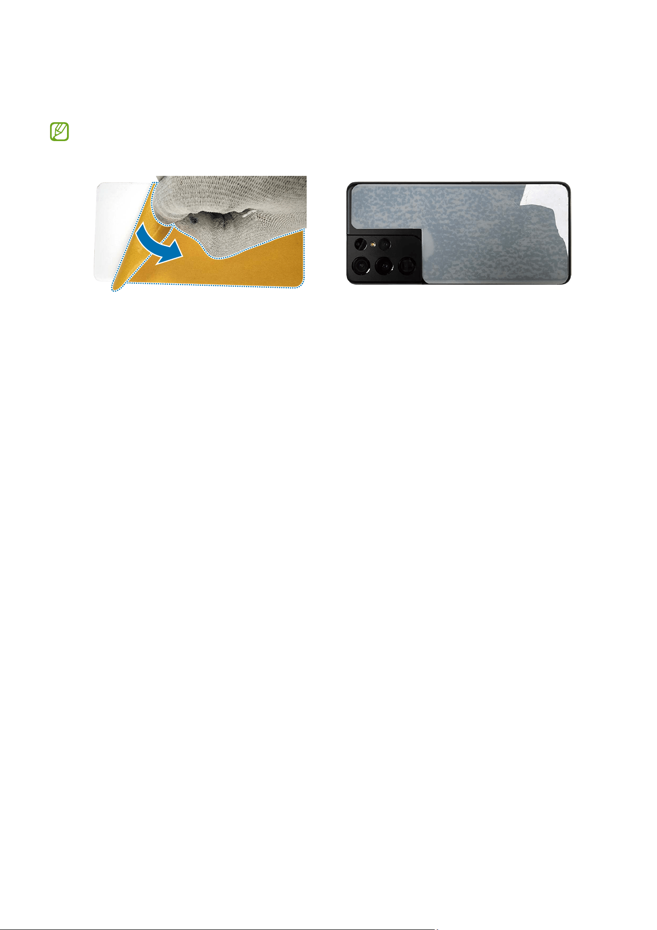
For all cases of broken glass:
1 Wear safety goggles and cut-resistant gloves.
2 Remove the release film of the acrylic protective cover.
3 To prevent injuries and scattering caused by broken glass, attach an acrylic protective
cover.
If your device’s glass breaks, be careful not to injure your hands or other body parts
on debris.
Disassembly and Assembly
55
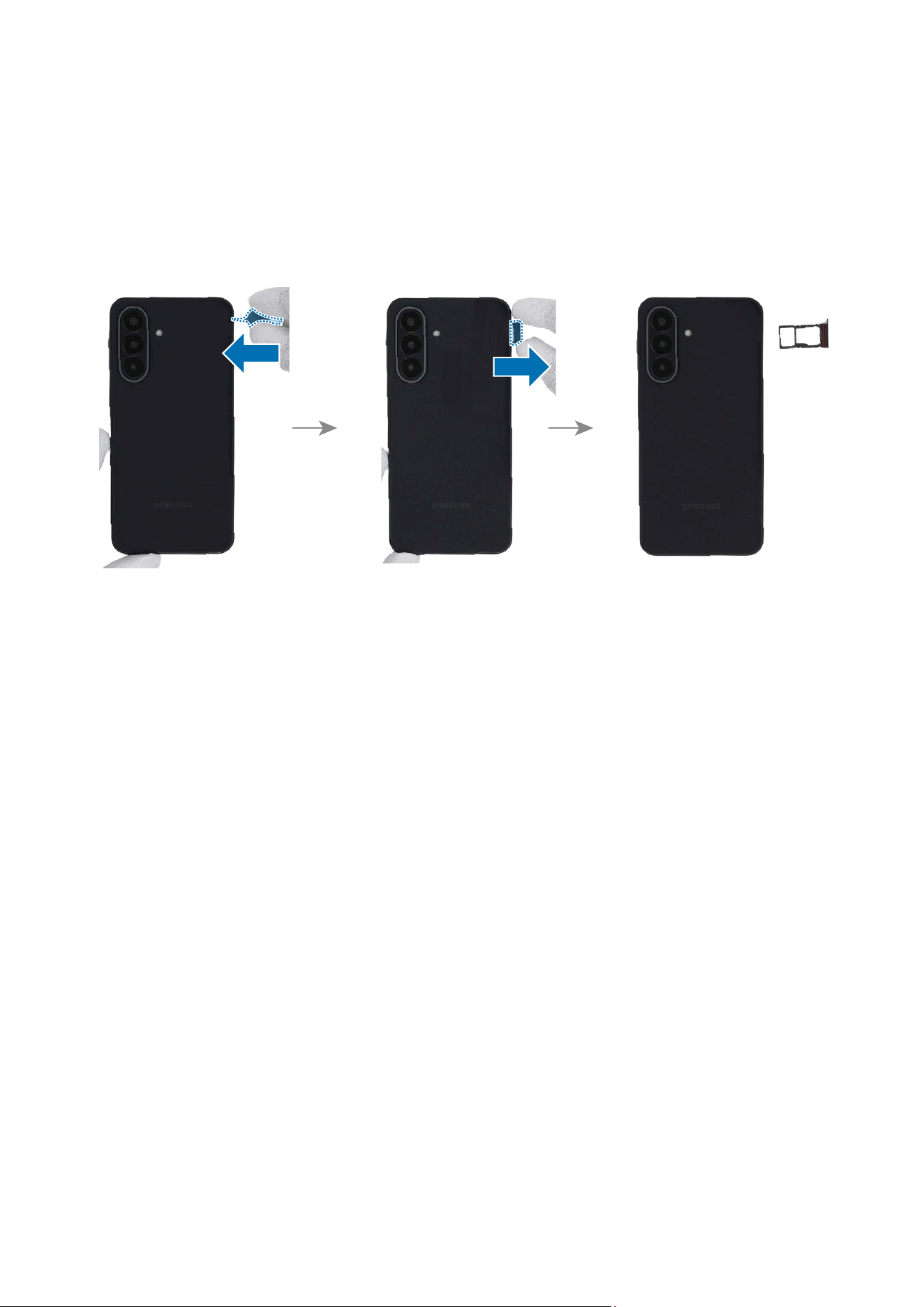
4 Press the acrylic protective cover with strong force so that it is strongly attached to
the glass.
Wait more than 5 minutes until the bond between the acrylic protective cover and
the glass is strengthened.
Acrylic protective cover
5 Follow the disassembly steps in this guide.
Disassembly and Assembly
56
SIM Card Tray
Disassembly
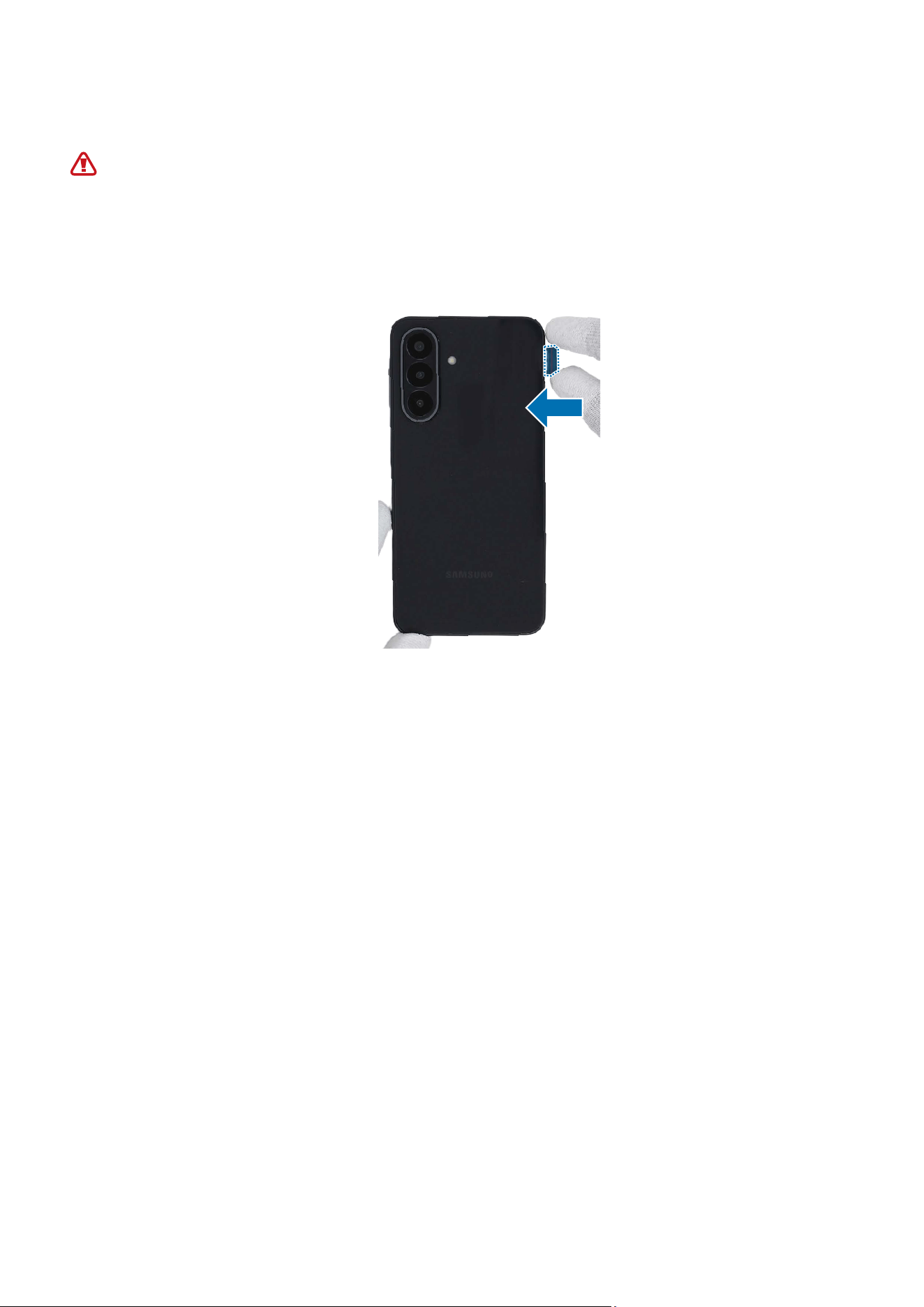
Prepare the device to repair by yourself. Insert the ejection pin into the hole of the SIM
card tray to loosen the tray and pull out the tray gently from the tray slot.
Disassembly and Assembly
57
Reassembly
Leaving screws inside the device may damage internal components, such as the
battery. When assembling, be extra careful not to leave any unassembled screws
inside the device.
Insert the SIM card tray back into the slot. Ensure that there are no abnormalities.
Disassembly and Assembly
58
Back Cover
Disassembly
When removing the back cover, ensure that the device is fixed on a flat surface.
Remove the SIM Card Tray first before you begin.
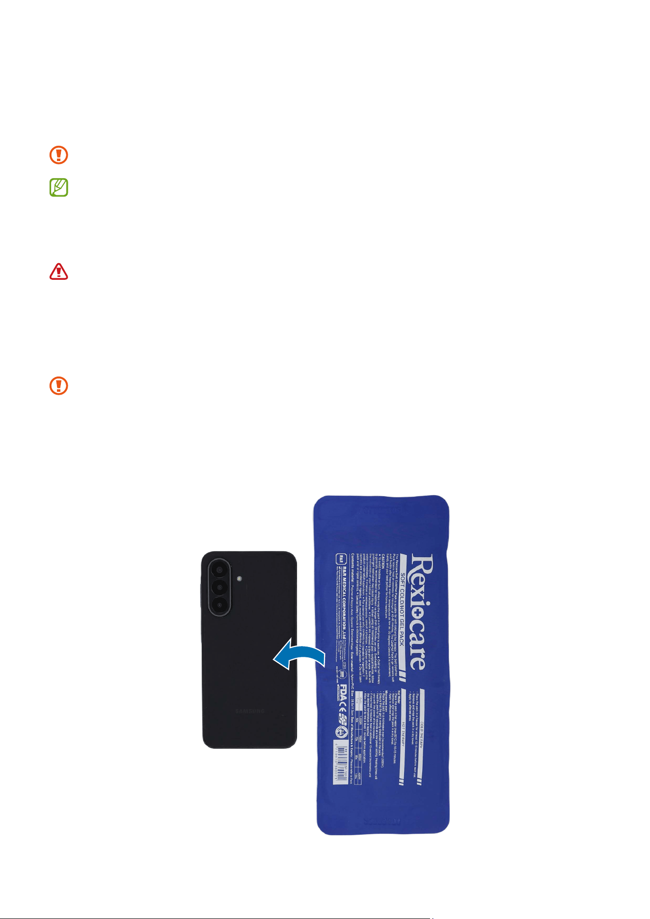
1 Heat the microwaveable heating bag and apply it on the back cover for 3 minutes to
soften the adhesive.
•
It is possible for the device or battery to be damaged by heat.
•
Do not heat the device in a microwave. Doing so could cause an explosion.
•
If your device’s glass breaks, the debris can cause injury to your hands or
other body parts. For your safety, attach an acrylic protective cover before
disassembling the device.
•
Follow the heating bag’s instructions for heating. The recommended time for
heating the bag is 50 seconds in a 1000 W microwave and 70 seconds in a 700 W
microwave. (Correct temperature for use: 55-65 ℃.)
•
Be careful not to damage the device through excessive heat. (It is recommended
to disassemble the device in an area with a temperature gauge.)
Disassembly and Assembly
59
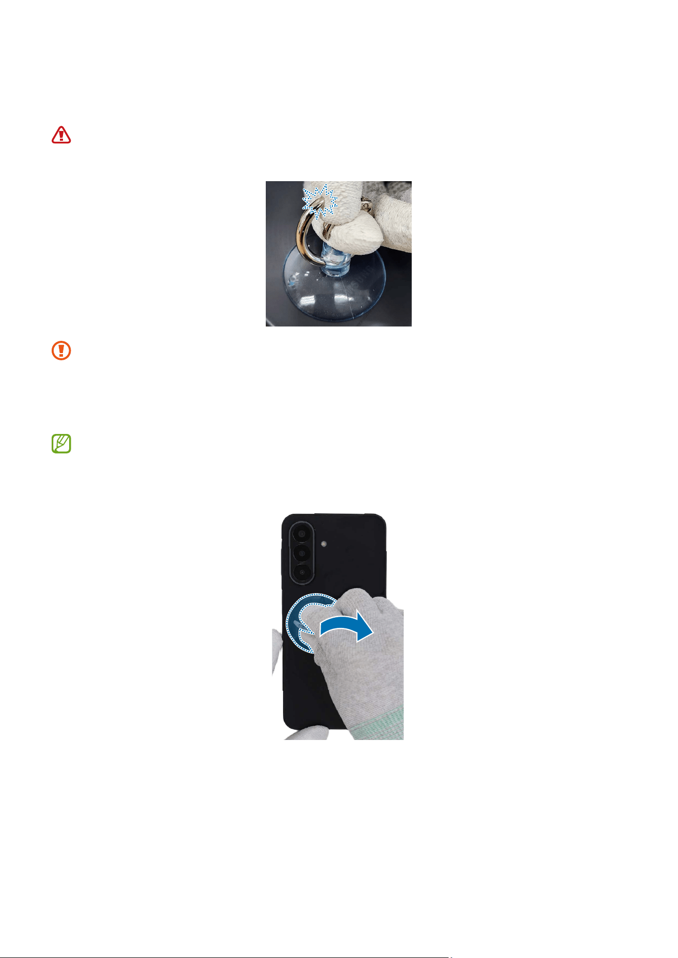
2 Place the suction cup in the centre of the left edge of the back cover, and lift it
upwards carefully.
For separable handle suction cups, be careful not to injure yourself as the handle
can be parted during use.
•
As the back cover can be damaged by excessive force, be careful not to damage
the back cover.
•
Be careful that the suction cup does not adhere to the area where the tape or
sticker is attached.
If you have trouble creating a gap, heat the microwaveable heating bag
additionally, and apply it on the back cover to further soften the adhesive. When
reheating, it should be heated no longer than 30 seconds.

Disassembly and Assembly
60
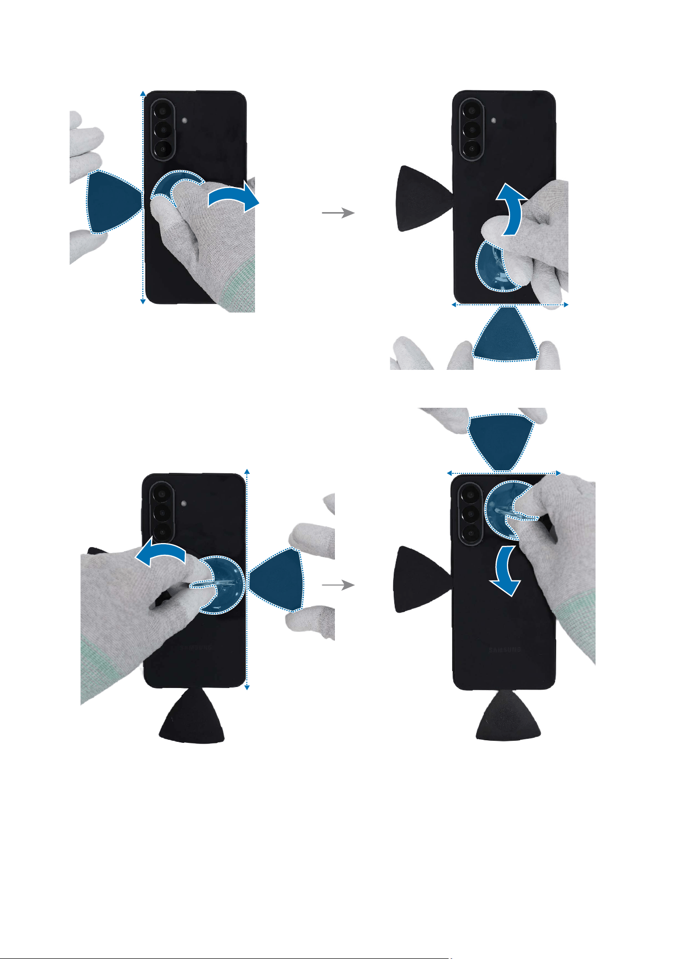
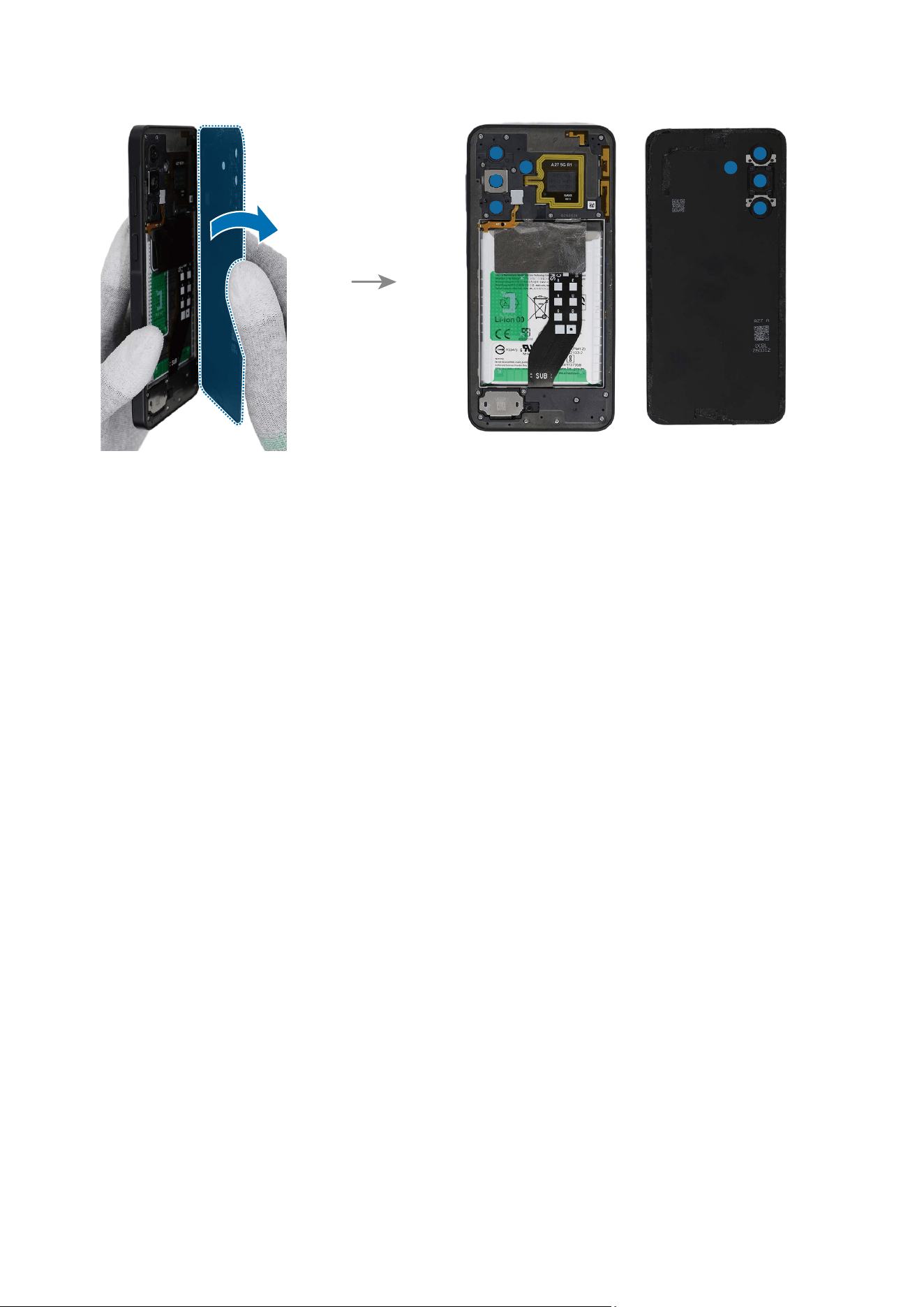
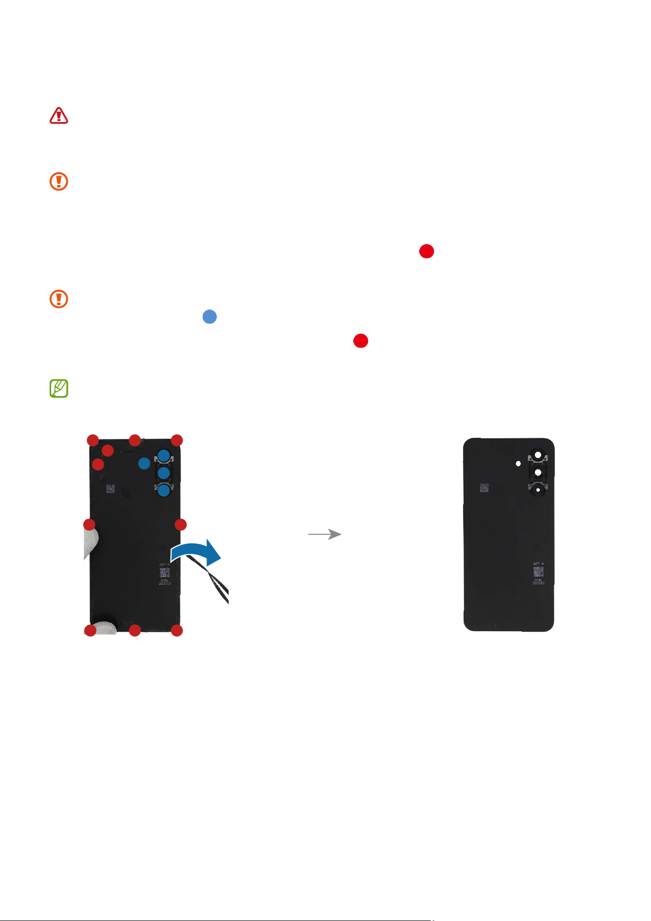
3 While pulling up the suction cup with strong, steady force to create the gap between
the back cover and the metal frame, place the opening pick in the gap between the
back cover and the metal frame and slide the opening pick back and forth along the
edge to slice through the adhesive. Repeat this on all the sides of the back cover and
slice through the adhesive. Lift up the back cover slowly and remove it gently from
the device.
•
As the back cover can be damaged by excessive force, be careful not to damage
the back cover.
•
As the internal circuitry can be damaged, do not insert the opening pick more
than 3 mm.
•
Be careful not to put your fingertips or any foreign objects on the rear cameras
or back cover lens (
).
•
Make sure to leave the opening pick inserted in the edges to prevent the
adhesive from resealing. It is recommended that a larger area of the opening
pick be inserted.
•
If you have trouble creating a gap, heat the microwaveable heating bag
additionally, and apply it on the back cover to further soften the adhesive. When
reheating, it should be heated no longer than 30 seconds.
Disassembly and Assembly
61
Disassembly and Assembly
62
Disassembly and Assembly
63
Reassembly
Leaving screws inside the device may damage internal components, such as the
battery. When assembling, be extra careful not to leave any unassembled screws
inside the device.
Before attaching the back cover, make absolutely sure that there are no screws,
miscellaneous parts, or other foreign objects on the inside of the device (among
the battery, PBA, etc.).
1 Remove all adhesive tapes on the separated back cover ( ) if you use the existing
back cover as it is.
•
Be careful not to put your fingertips or any foreign objects on the rear camera or
back cover lens (
).
•
Make sure to remove any residual tapes ( ) attached to the inside of the back
cover before reassembling the device.
Apply additional heat with a microwaveable heating bag if you’re having trouble
separating the adhesive.
Disassembly and Assembly
64
2 Remove the transparent film of the new back cover adhesive tape. Align the adhesive
tape precisely on the rear bracket and attach it.
3 Using the tweezers, gently press along the edges to ensure a secure fit.
Make sure the tape is attached correctly.
Disassembly and Assembly
65
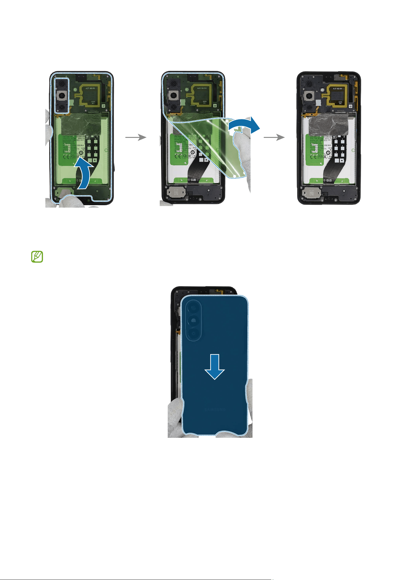
4 Remove the release film of the adhesive tape by grabbing the film handle.
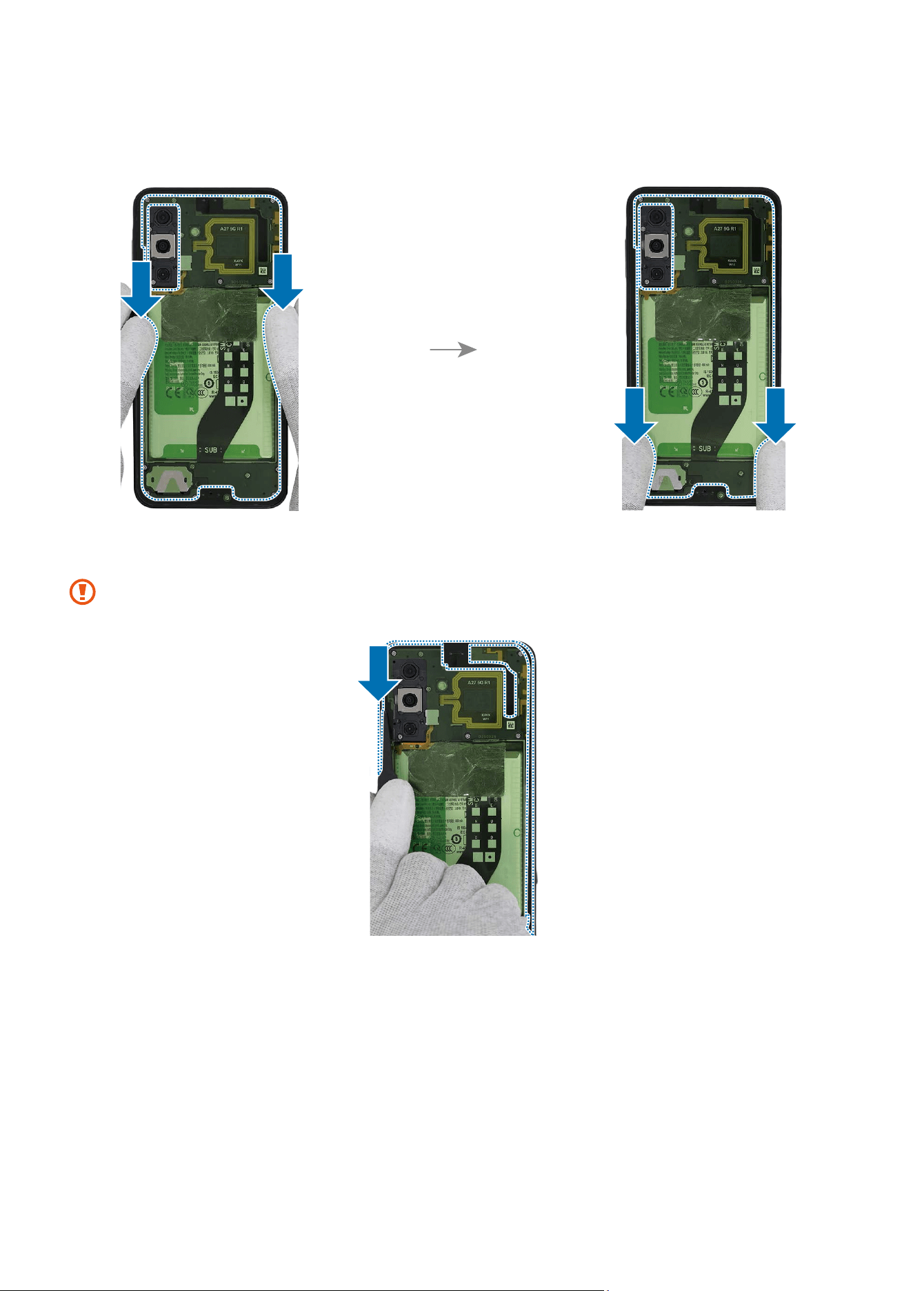
5 Attach the back cover and press down on the edges of the back cover. Check the gap
between back cover and the frame.
If you feel a gap, remove the back cover and attach it again. Some foreign
materials can be inside the device.
Disassembly and Assembly
66
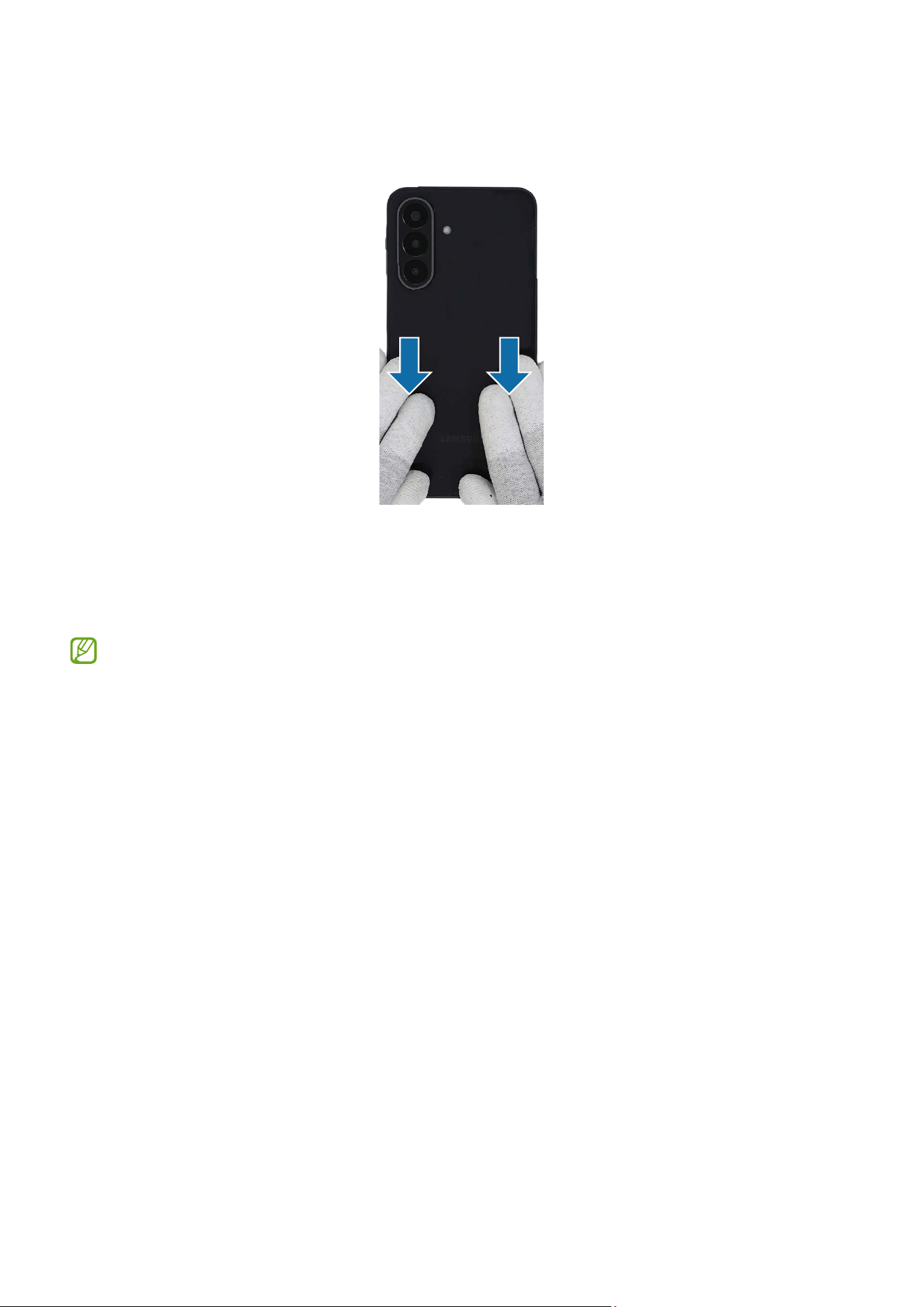
6 Press down the edges of the back cover evenly in order to attach the back cover
perfectly. Ensure that there are no abnormalities.
7 If the press tray is bundled with the repair parts you ordered, check for the steps of
the Back Cover Press. You can further press the fully assembled back cover using the
appropriate tool.
Availability of the bundle tool may vary depending on the country and are
currently available only in limited countries.
Disassembly and Assembly
67
Front Camera
Disassembly
Remove the SIM Card Tray and Back Cover first before you begin.
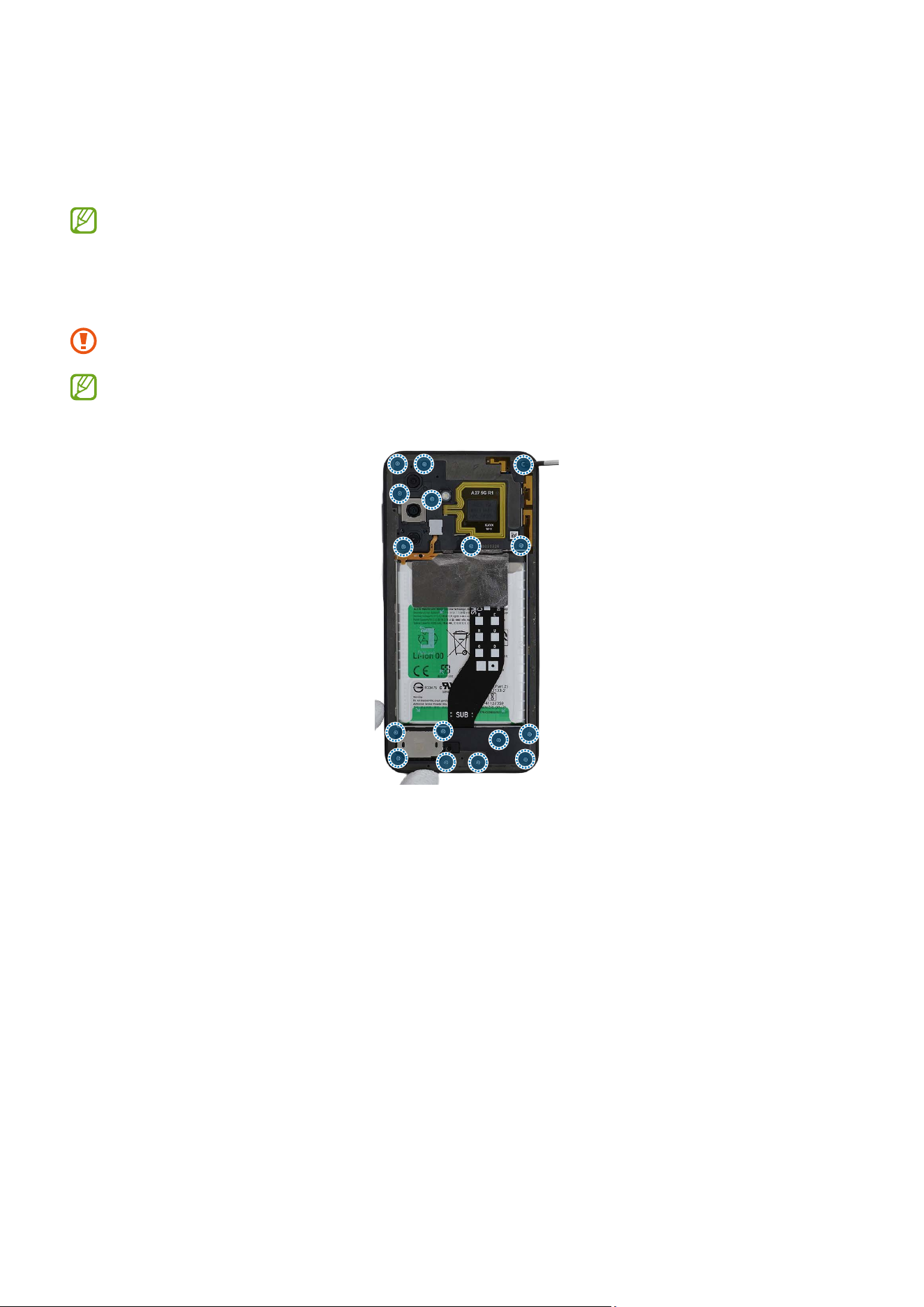
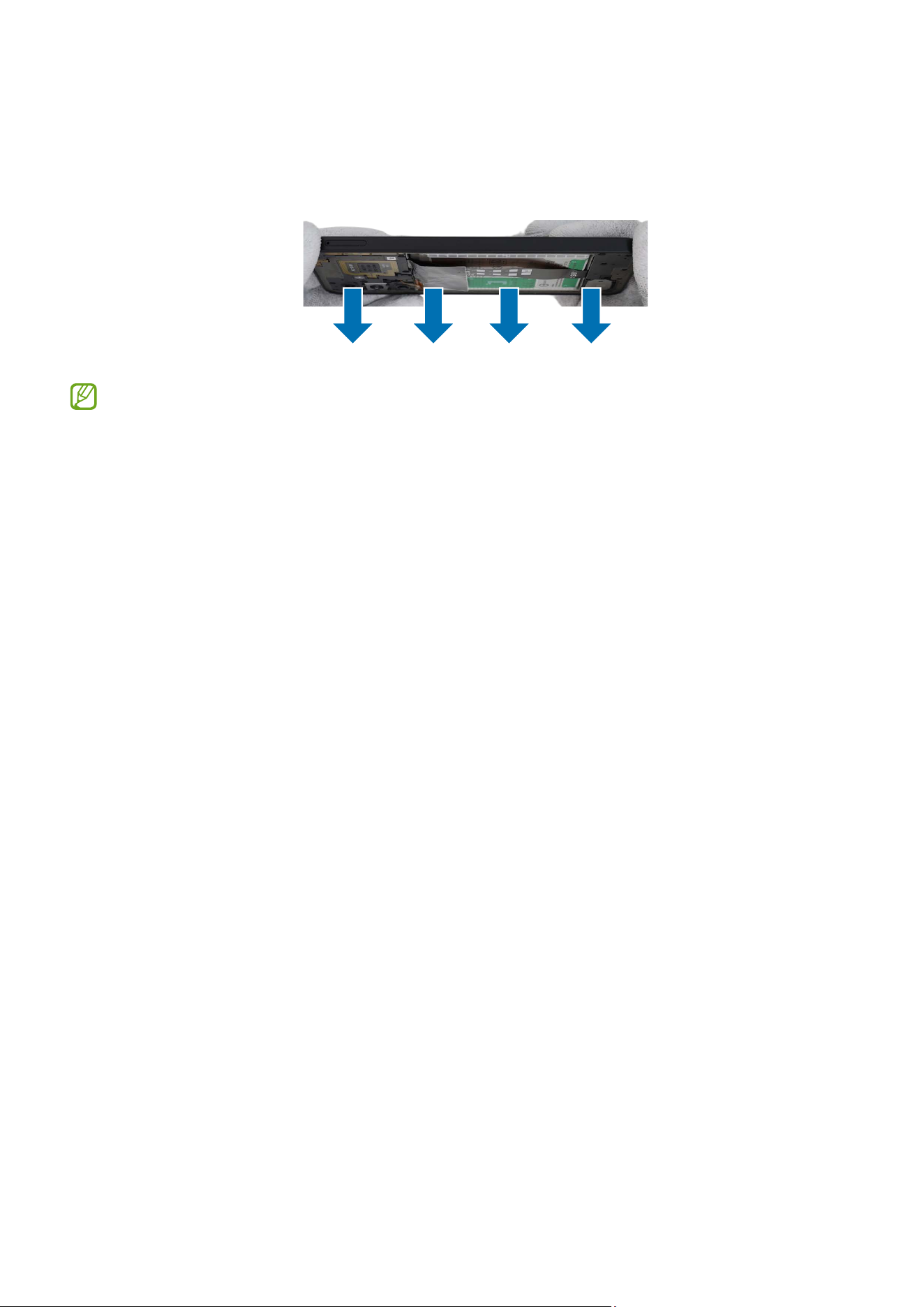
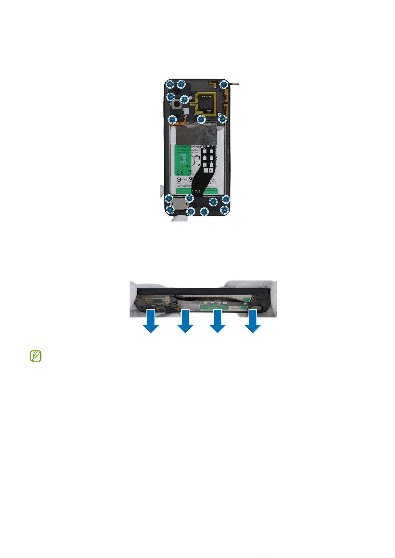
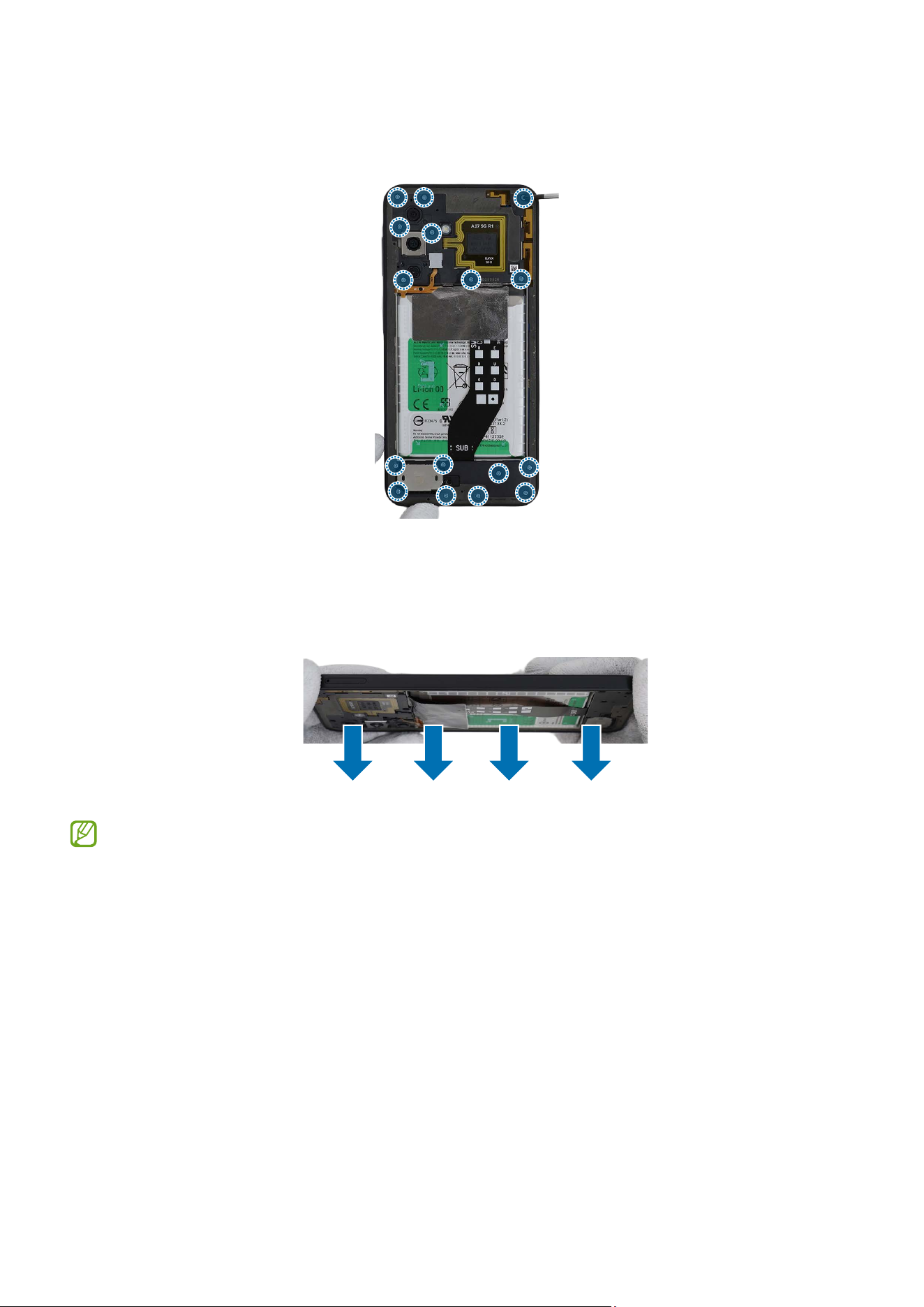
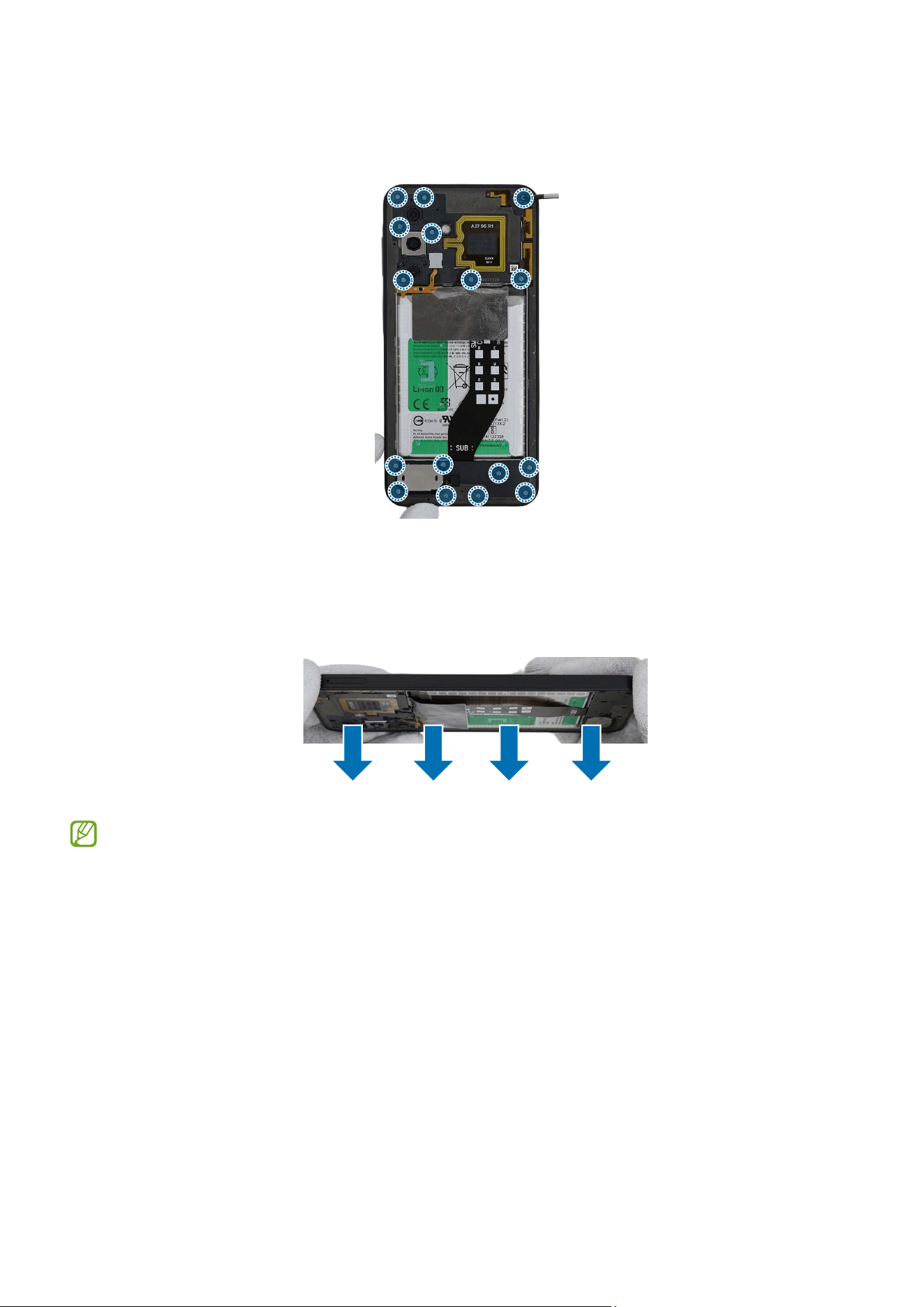
1 Check the screws at the 16 different points on the rear and remove them using a
cross-head screwdriver.
Be careful not to damage the near components.
Check the number of screws that have been removed, and store them carefully to
make sure that no unassembled screws are left inside the device during assembly.
Disassembly and Assembly
68
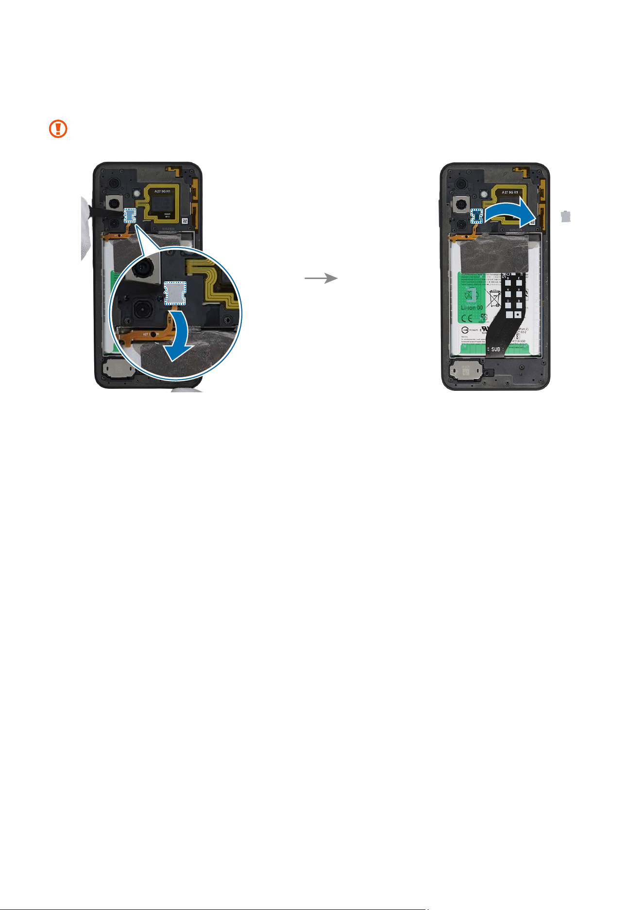
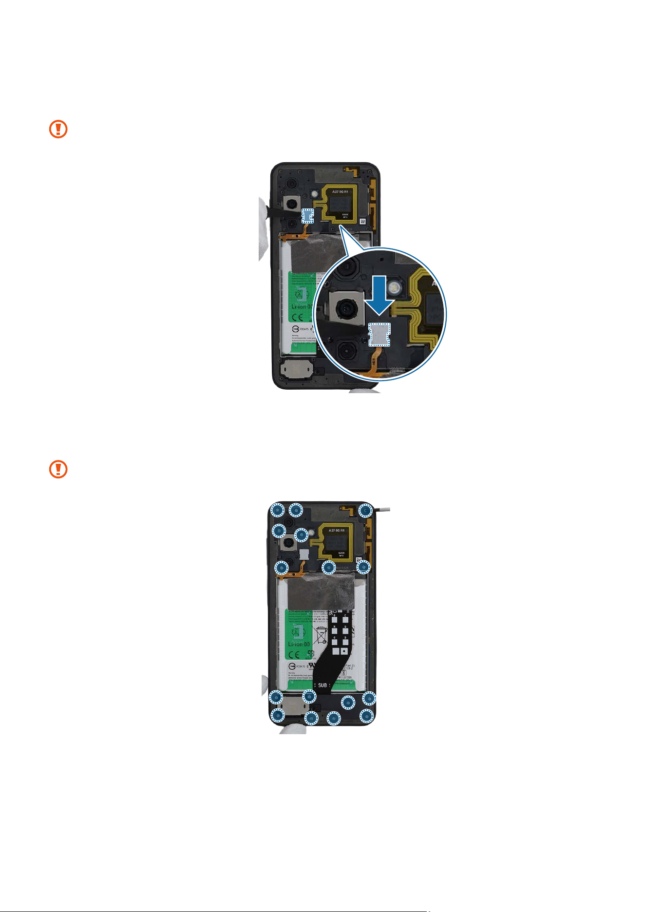
2 Using the tweezers, disconnect the fingerprint recognition sensor connector cover
and remove it completely.
Be careful not to lose the connector cover.
Disassembly and Assembly
69
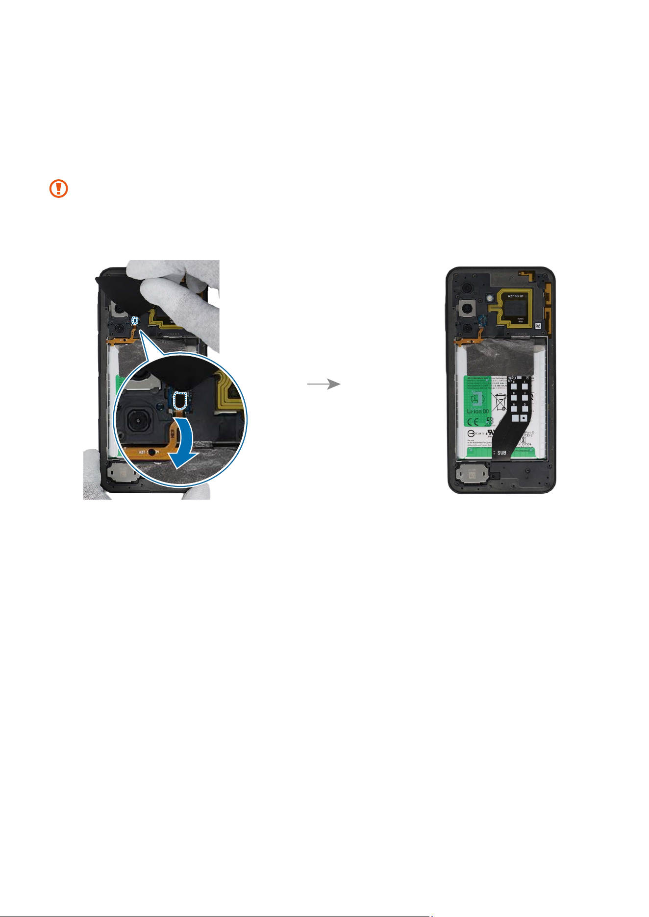
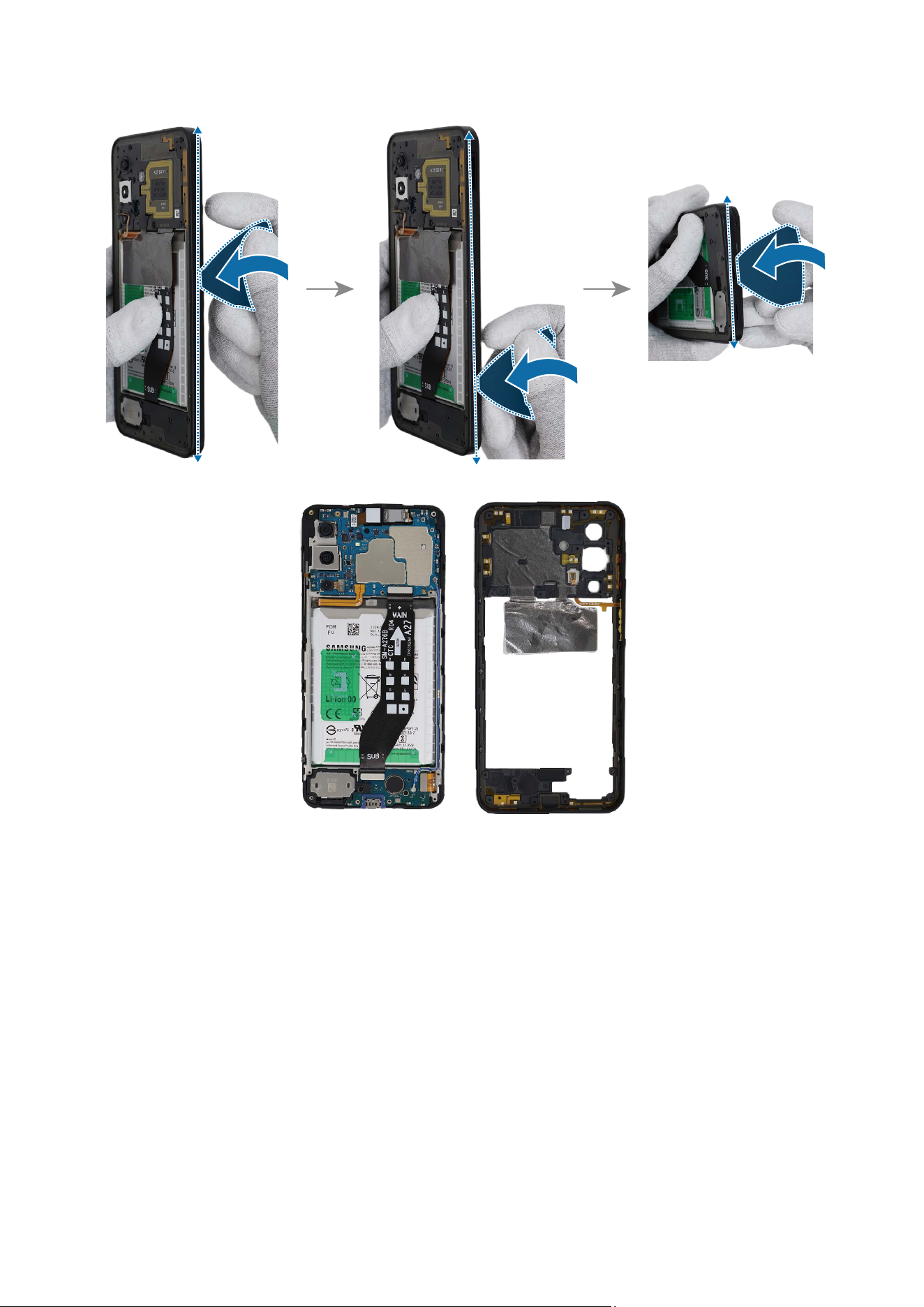
3 Using the opening pick, separate the fingerprint recognition sensor connector from
the main board. Insert the opening pick into the gap between the left edge of the
bracket and the device module, then widen the gap by moving it along the edge.
Carefully slide the opening pick around all sides to separate the bracket from the
screen module. Once fully detached, slowly lift the bracket.
•
Be careful not to damage the cable.
•
As the bracket can be damaged by excessive force, be careful not to damage the
bracket.
Disassembly and Assembly
70
Disassembly and Assembly
71
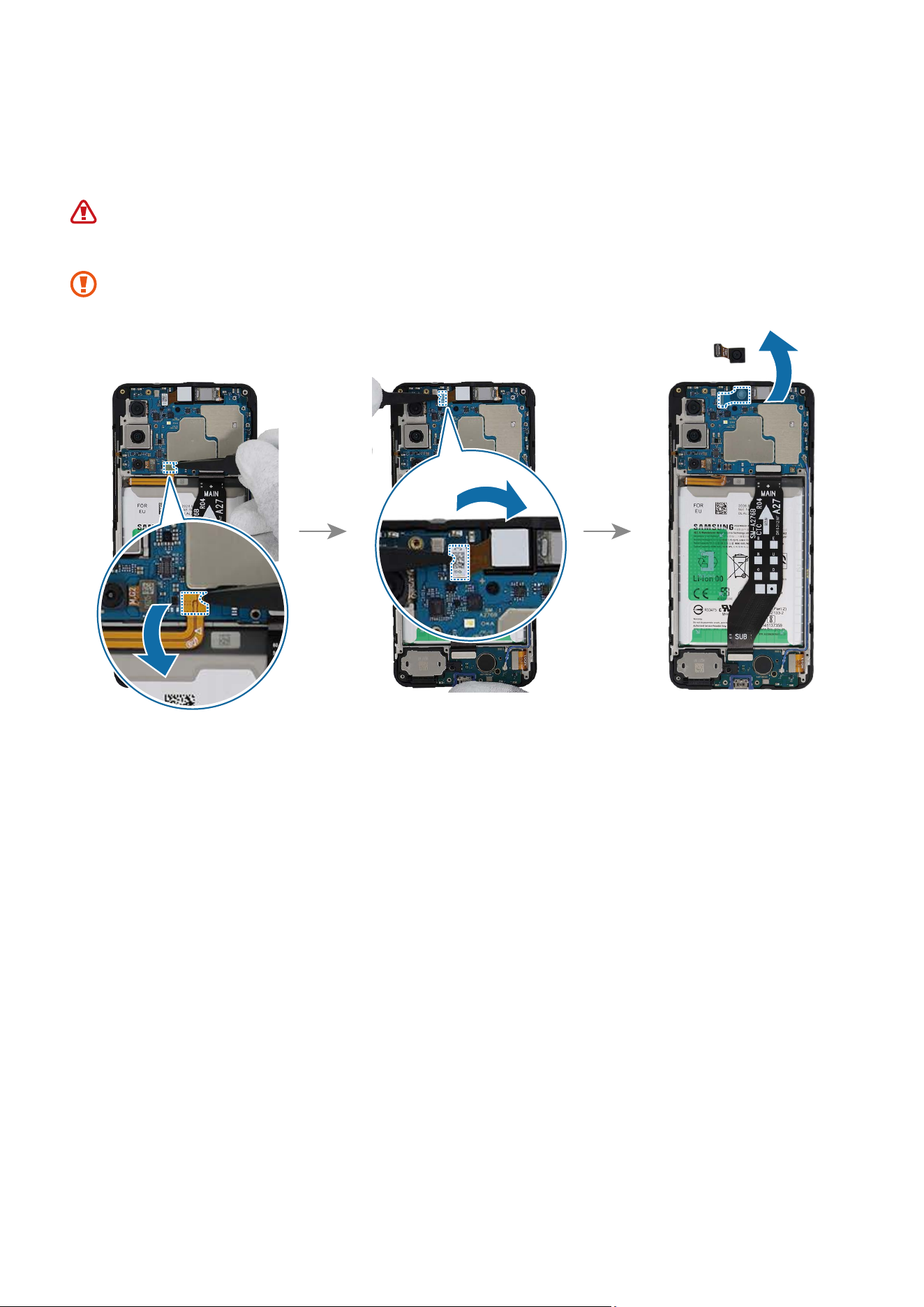
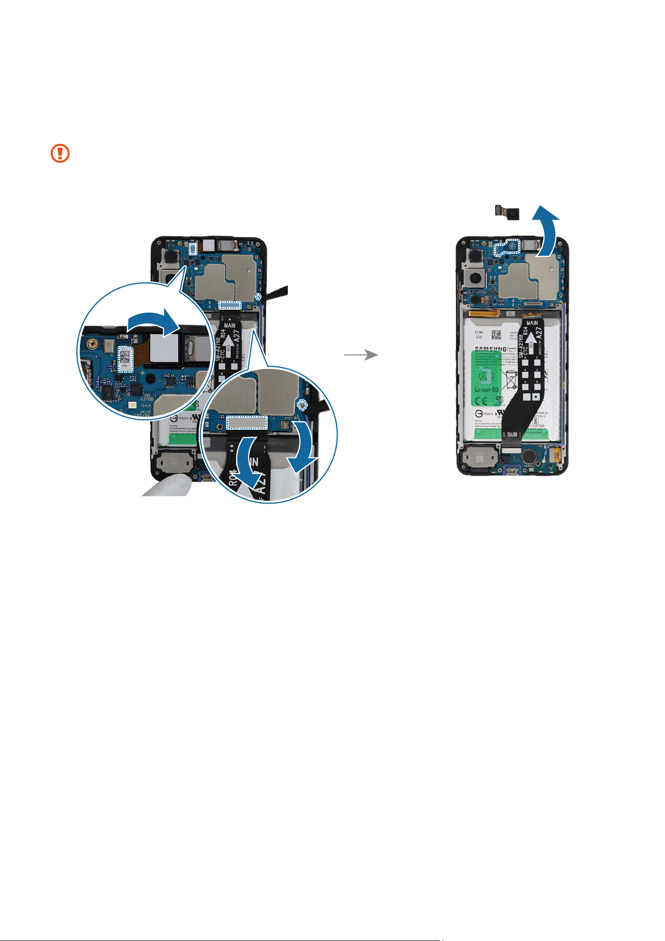
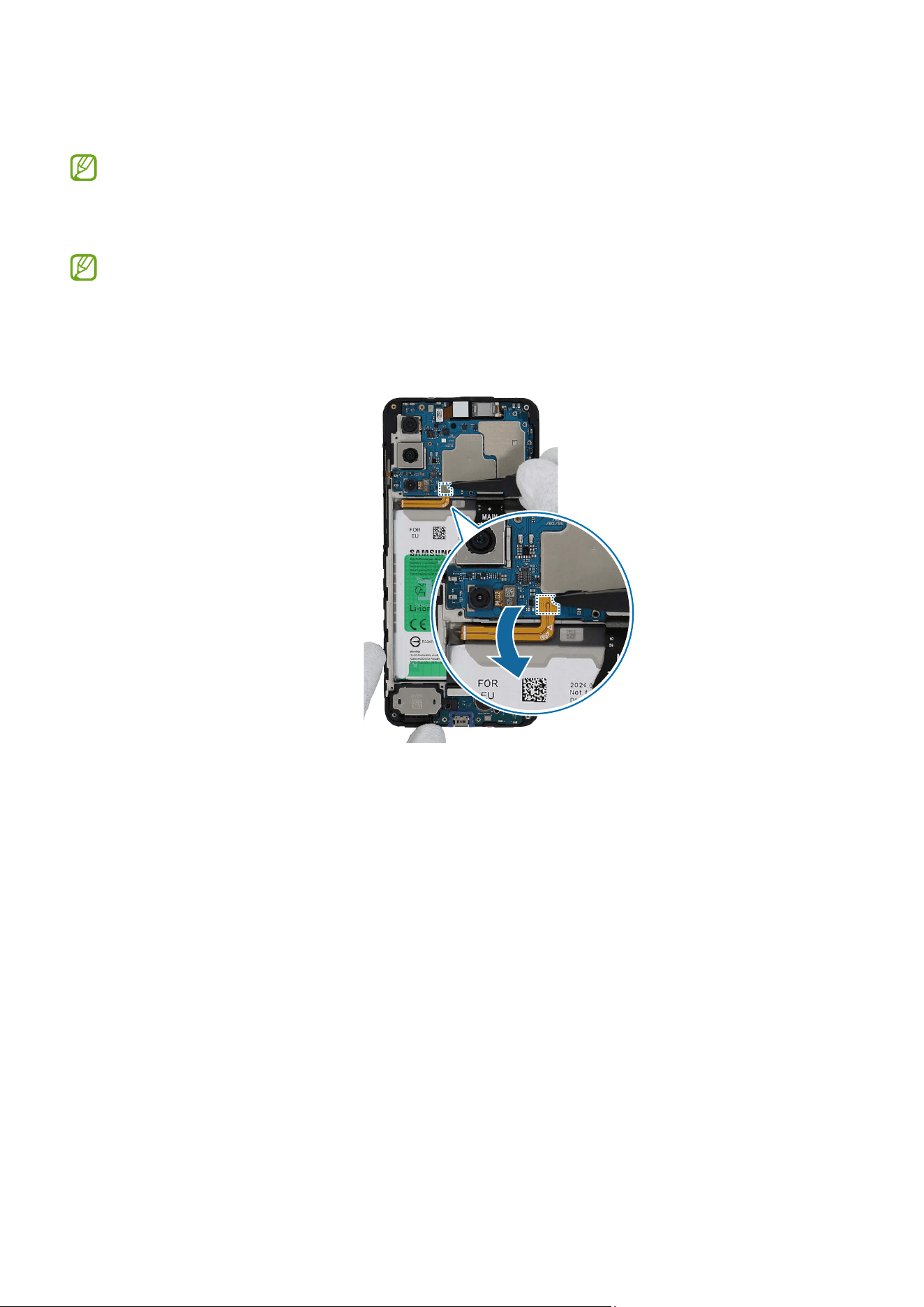
4 Using the tweezers, disconnect the battery connector first from the main board.
Separate the front camera connector from the main board and remove the front
camera carefully from the device. Leave the camera lens facing up.
•
Make sure to first disconnect the battery connector for your own safety.
•
Be careful not to damage the battery.
Be careful not to touch the camera lens while removing the camera.
Disassembly and Assembly
72
Reassembly
Leaving screws inside the device may damage internal components, such as the
battery. When assembling, be extra careful not to leave any unassembled screws
inside the device.
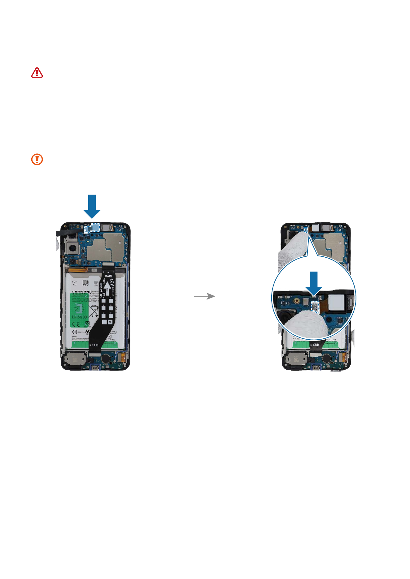
1 Using the tweezers or your fingers, place the new front camera in the camera hole so
that the lens faces forward and gently insert. Then, connect the camera connector
carefully on the main board.
•
Be careful not to damage the camera lens and the near components.
•
Be careful not to damage the main board.
Disassembly and Assembly
73
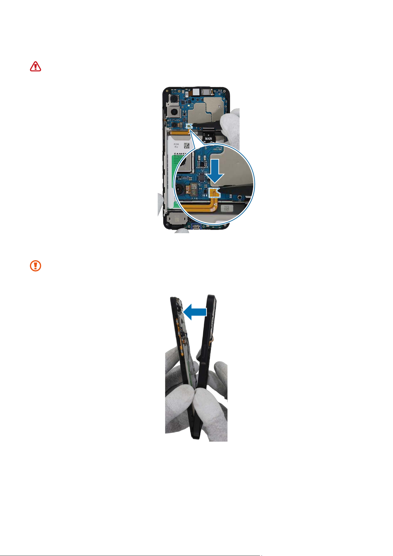
2 Connect the battery connector to the main board.
Be careful not to damage the battery.
3 Attach the rear bracket carefully from the bottom.
As the bracket can be damaged by excessive force, be careful not to damage the
bracket.
Disassembly and Assembly
74
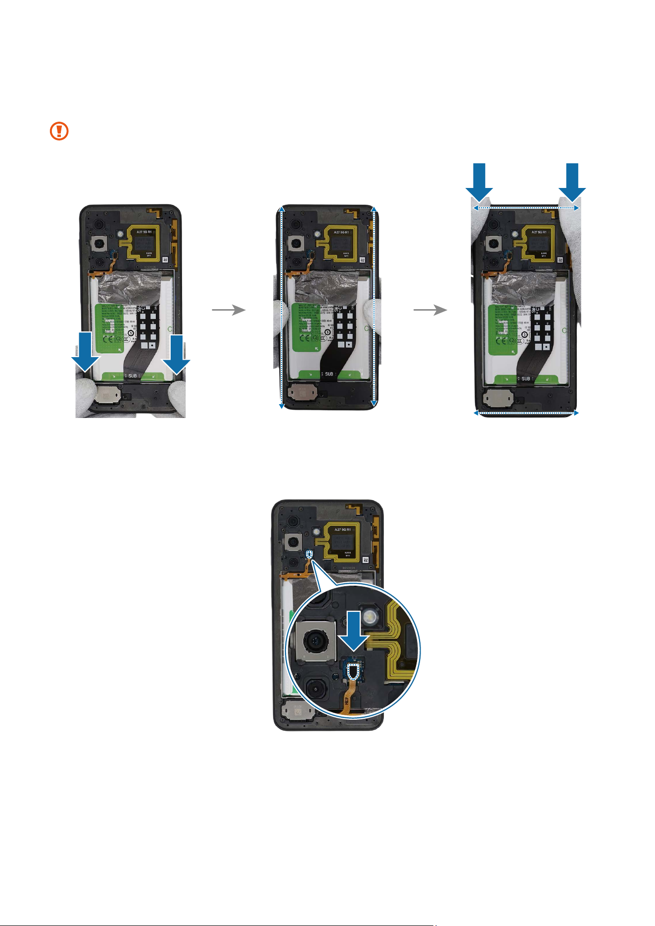
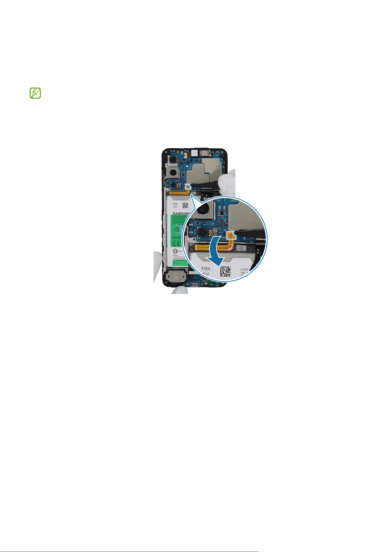
4 Push down all edges of the rear bracket with your fingers softly and evenly so that the
rear bracket can be assembled perfectly.
Be careful not to damage the near components.
5 Using the tweezers, connect the fingerprint recognition sensor connector to the main
board.
Disassembly and Assembly
75
6 Using the tweezers or your fingers, position the fingerprint recognition sensor
connector cover in the rear bracket hole and gently press it down to secure it in place.
Be careful not to damage the cable.
7 Check the screw 3532 (16 ea) at the 16 different points on the rear and fasten them
using a cross-head screwdriver.
Be careful not to damage the near components.
Disassembly and Assembly
76
8 Check carefully with your fingers to see if there are any screws or other foreign
substances inside the device (battery, PBA, cable, etc.). Shake the device lightly with
the back of the device facing down to remove any remaining screws.
Reassemble the Back Cover and SIM Card Tray to complete assembly.
Disassembly and Assembly
78
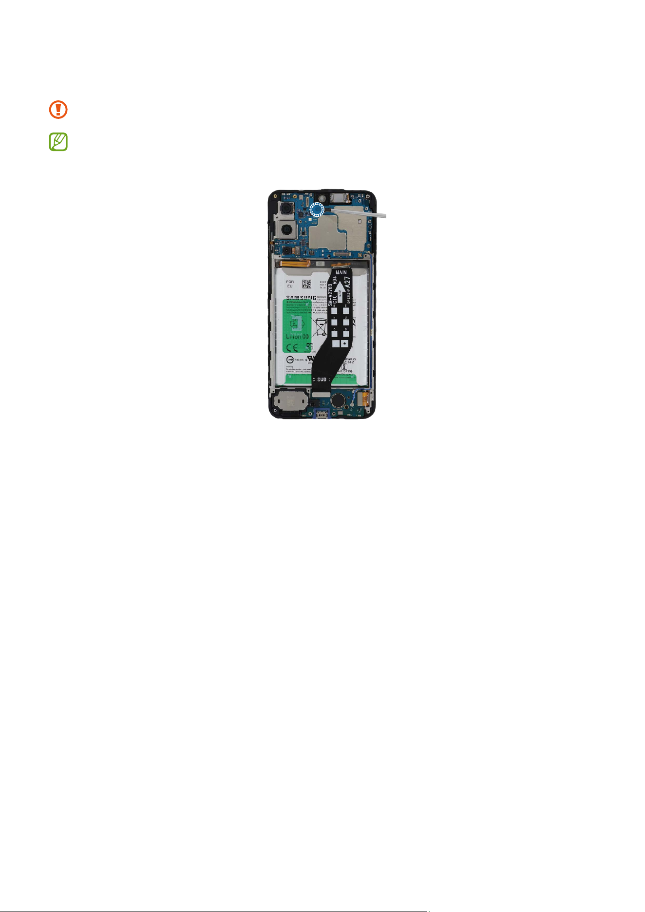
2 Using the tweezers, disconnect the coaxial cable, front camera connector, and FPCB
connector from the main board. And then, remove the front camera carefully from
the device. Leave the camera lens facing up.
•
Be careful not to damage the main board.
•
Be careful not to touch the camera lens while removing the camera.
Disassembly and Assembly
79
3 Check the 1 screw on the main board and remove it using a cross-head screwdriver.
Be careful not to damage the main board and near components.
Check the number of screws that have been removed, and store them carefully to
make sure that no unassembled screws are left inside the device during assembly.
Disassembly and Assembly
80
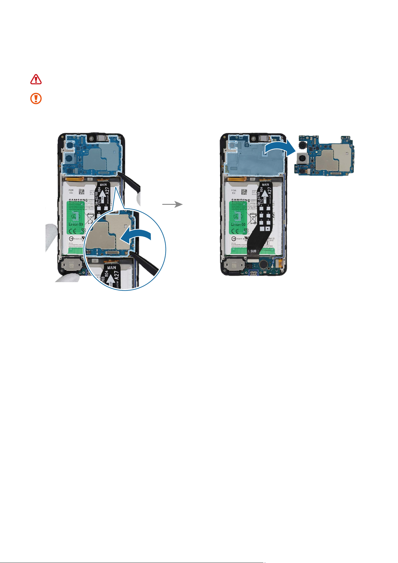
4 Using the tweezers, lift up on the separator groove of the main board and remove it
carefully.
Be careful not to damage the battery.
The FPCB cables have to be positioned outside so as not to interfere when
disassembling the main board.
Disassembly and Assembly
81
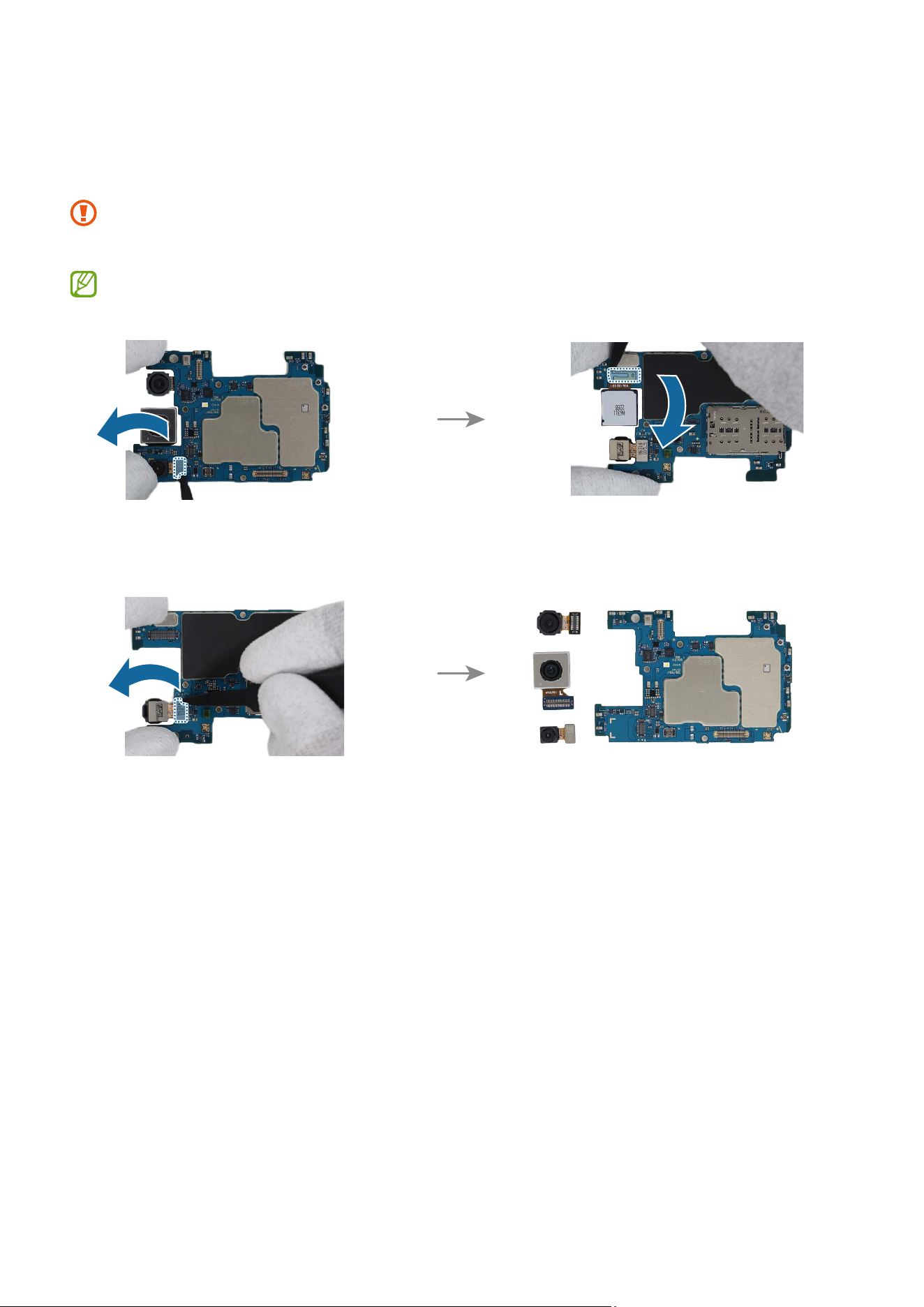
5 Disconnect the rear camera connector from the main board using the tweezers, and
remove the rear camera carefully from the main board. Leave the camera lens facing
up.
•
Be careful not to damage the main board.
•
Be careful not to touch the camera lens while removing the camera.
Separate and replace only the problematic camera.
Disassembly and Assembly
82
Reassembly
Leaving screws inside the device may damage internal components, such as the
battery. When assembling, be extra careful not to leave any unassembled screws
inside the device.
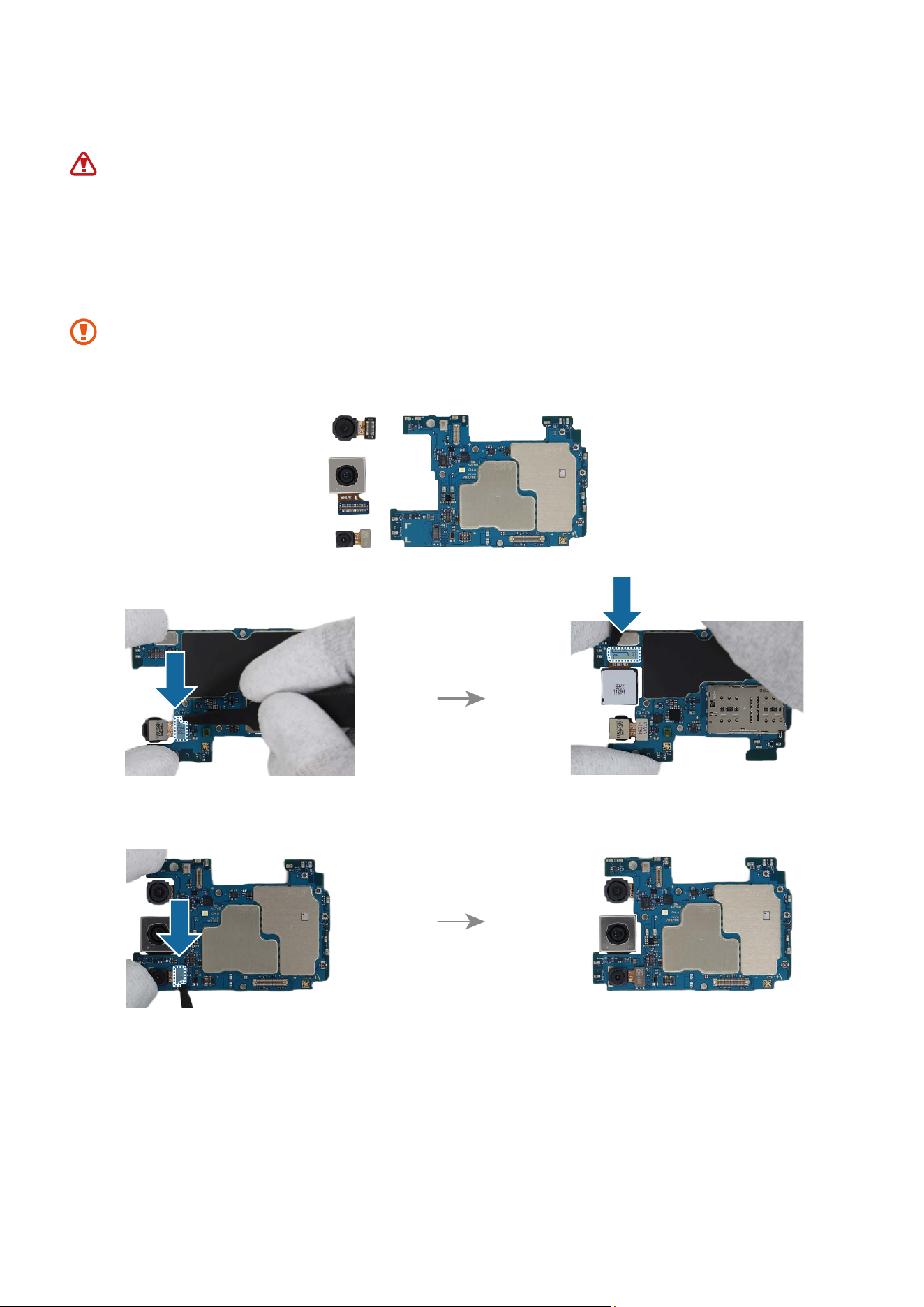
1 Using the tweezers, connect the rear camera connectors to the main board. Leave the
camera lens facing up.
•
Be careful not to damage the camera lens and the near components.
•
Be careful not to damage the main board.
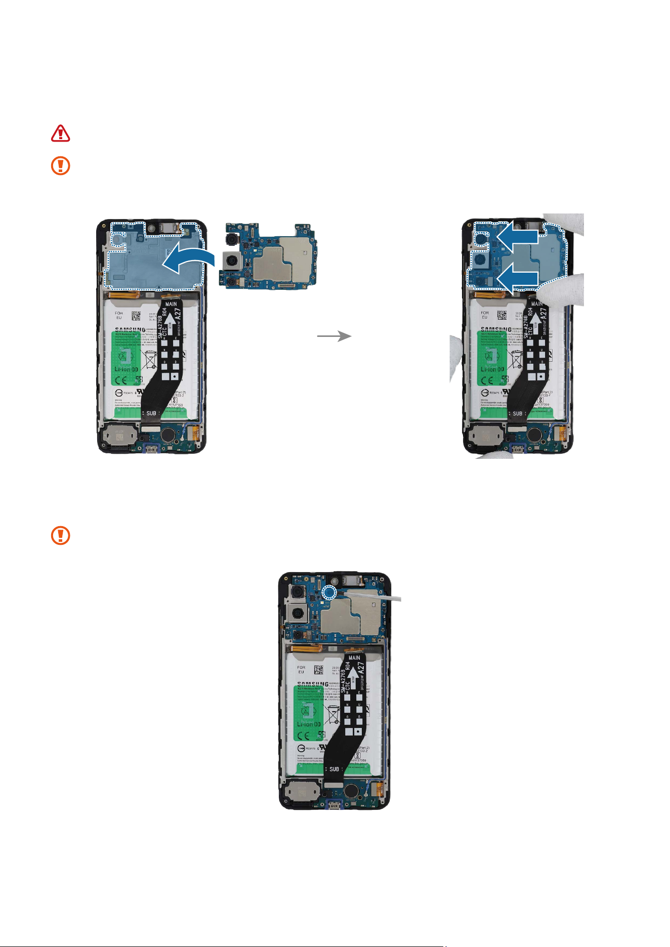
Disassembly and Assembly
83
2 Align the main board onto the device frame. After attaching the left part of the main
board on the metal frame, assemble the right part.
Be careful not to damage the battery.
The FPCB cables and coaxial cable have to be positioned outside so as not to
interfere when assembling the main board.
3 Check the screw 3637 (1 ea) on the main board and fasten it using a cross-head
screwdriver.
Be careful not to damage the near components.
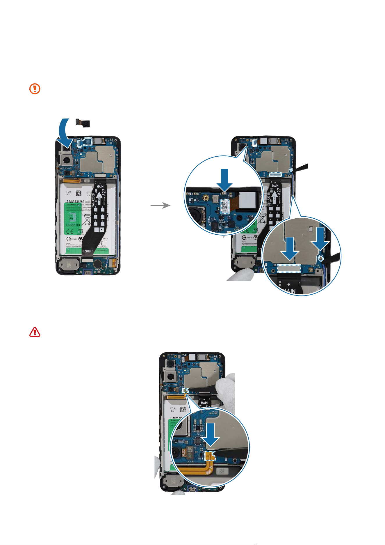
Disassembly and Assembly
84
4 Using the tweezers or your fingers, place the front camera in the camera hole so that
the lens faces forward and gently insert. Then, connect 3 connectors carefully on the
main board.
•
Be careful not to damage the camera lens and the near components.
•
Be careful not to damage the main board.
5 Connect the battery connector to the main board.
Be careful not to damage the battery.
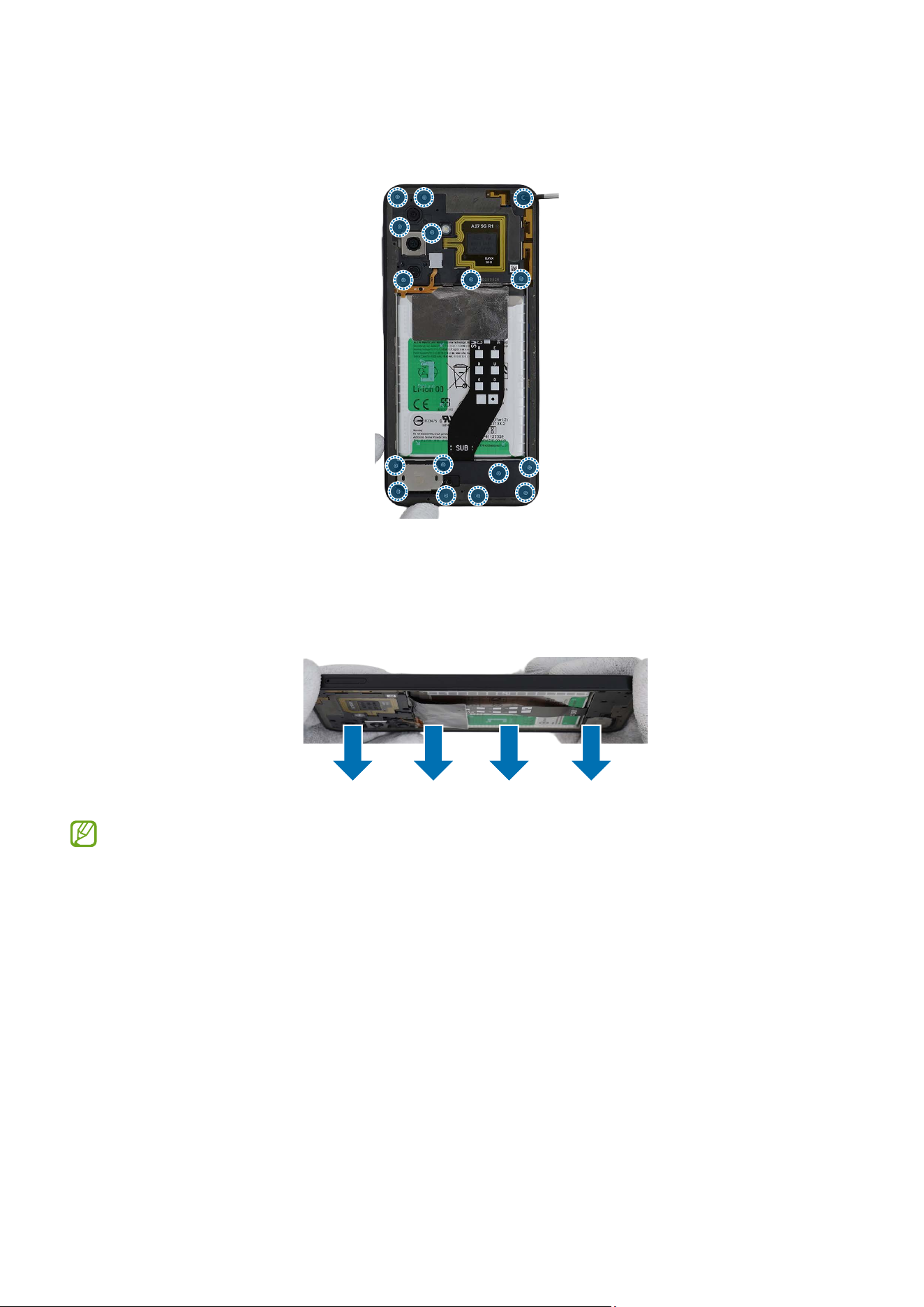
Disassembly and Assembly
85
6 Check for the reassembly steps of the Front Camera and completely reassemble the
bracket.
7 Check carefully with your fingers to see if there are any screws or other foreign
substances inside the device (battery, PBA, cable, etc.). Shake the device lightly with
the back of the device facing down to remove any remaining screws.
Reassemble the Back Cover and SIM Card Tray to complete assembly.
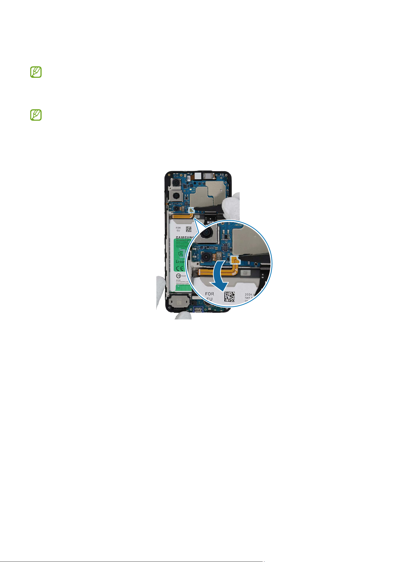
Disassembly and Assembly
87
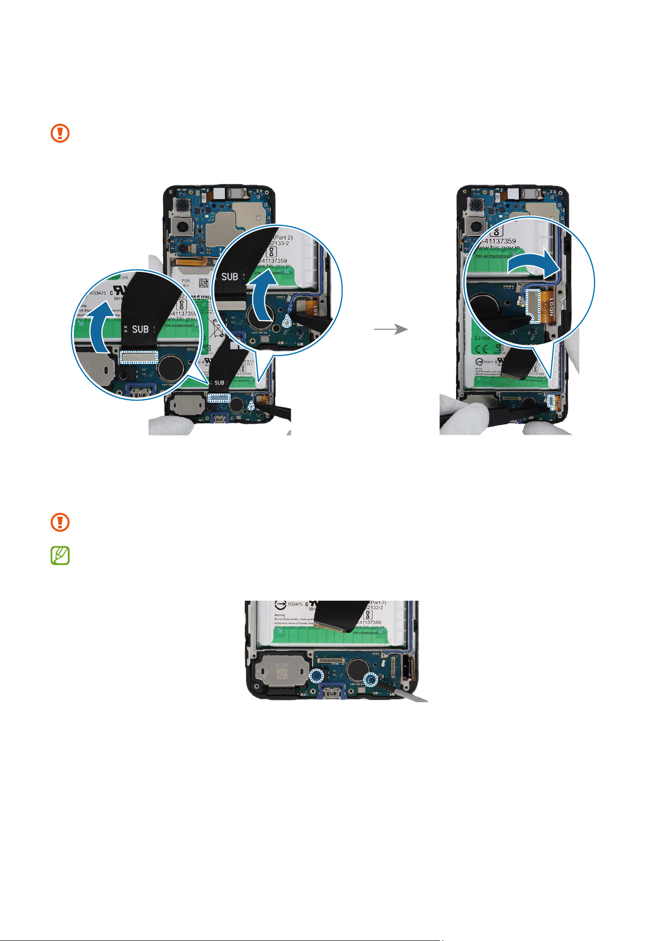
2 Using the tweezers, disconnect the coaxial cable, display connector, and FPCB
connector from the charging port module.
Be careful not to damage the charging port module.
3 Check the screws at the 2 different points and remove them using a cross-head
screwdriver.
Be careful not to damage the near components.
Check the number of screws that have been removed, and store them carefully to
make sure that no unassembled screws are left inside the device during assembly.
Disassembly and Assembly
88
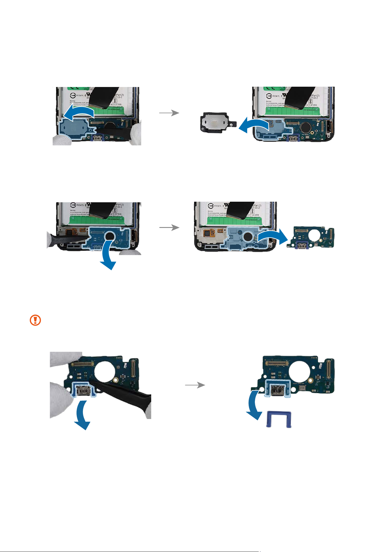
4 Using the tweezers, lift up on the separator groove of the bottom speaker and remove
it carefully.
5 And then, lift up on the separator groove of the charging port module and remove it
carefully.
6 Using tweezers, separate the charging port rubber carefully from the charging port
module.
The charging port rubber should be used again when reassembling, so be careful
not to lose it.
Disassembly and Assembly
89
Reassembly
Leaving screws inside the device may damage internal components, such as the
battery. When assembling, be extra careful not to leave any unassembled screws
inside the device.
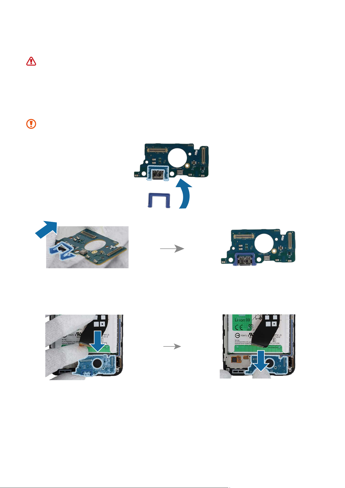
1 Using tweezers, assemble the charging port rubber carefully from the new charging
port module.
Be careful not to damage the charging port.
2 Using the tweezers or your fingers, insert the new charging port module to the
bottom metal frame of the device and press down on it in its position smoothly.
Disassembly and Assembly
90
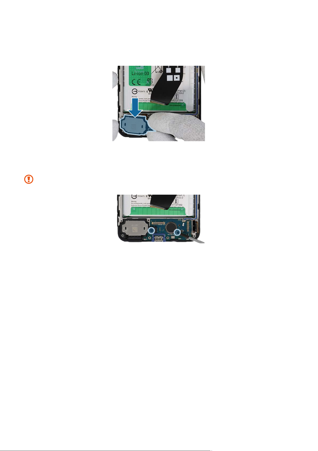
3 And then, insert the bottom speaker to the bottom metal frame of the device and
press down on it in its position smoothly.
4 Check the screw 3637 (2 ea) at the 2 different points on the charging port module and
fasten them using a cross-head screwdriver.
Be careful not to damage the charging port and the near components.
Disassembly and Assembly
91
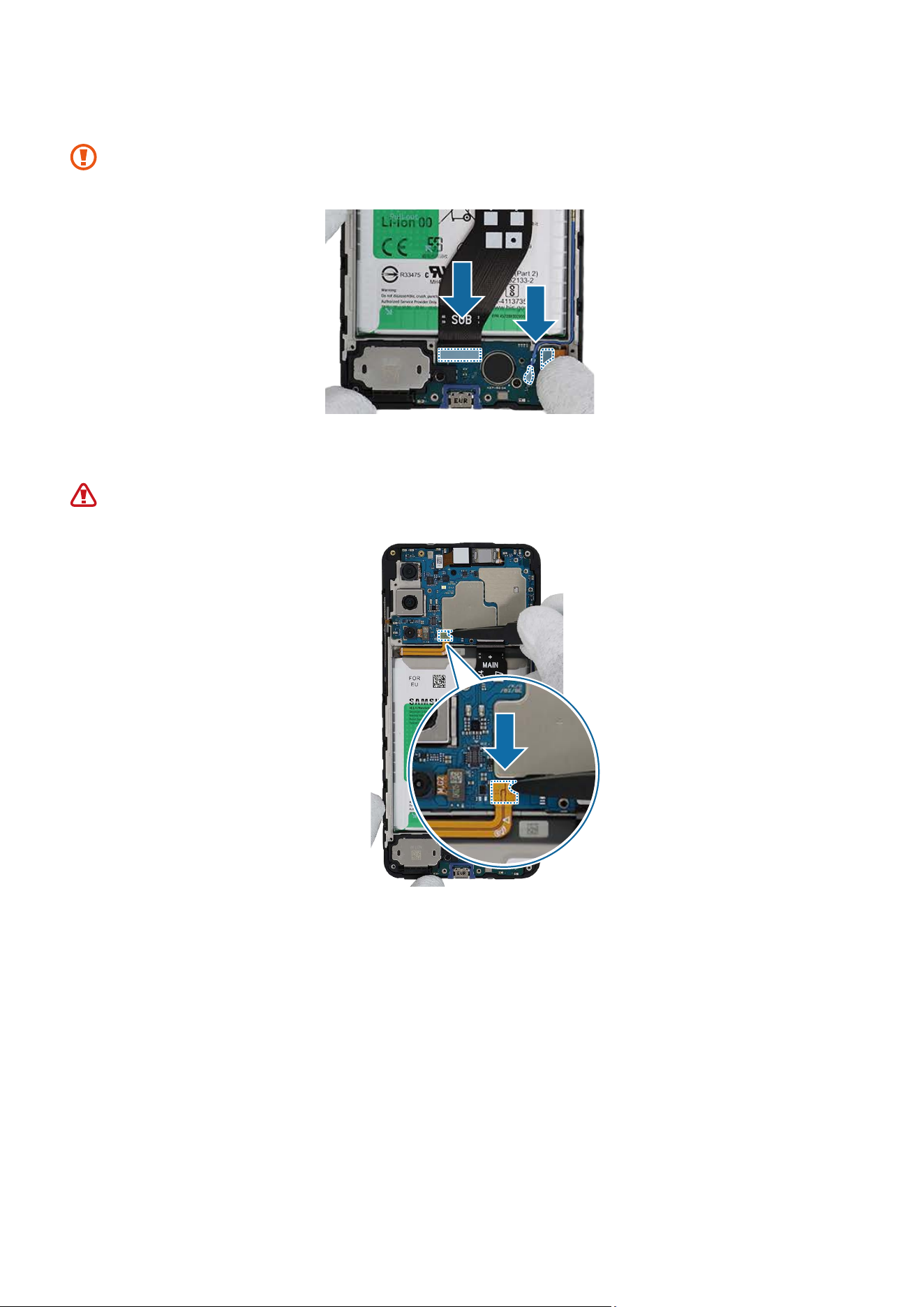
5 Using the tweezers or your fingers, connect the 3 connectors to the charging port.
Be careful not to damage the charging port.
6 Connect the battery connector to the main board.
Be careful not to damage the battery.
Disassembly and Assembly
92
7 Check for the reassembly steps of the Front Camera and completely reassemble the
bracket.
8 Check carefully with your fingers to see if there are any screws or other foreign
substances inside the device (battery, PBA, cable, etc.). Shake the device lightly with
the back of the device facing down to remove any remaining screws.
Reassemble the Back Cover and SIM Card Tray to complete assembly.
Disassembly and Assembly
93
Top Speaker
The top speaker is already built into the screen module. Disassemble the speaker
only if the speaker itself requires repairs.
Disassembly
Remove the SIM Card Tray and Back Cover first before you begin.
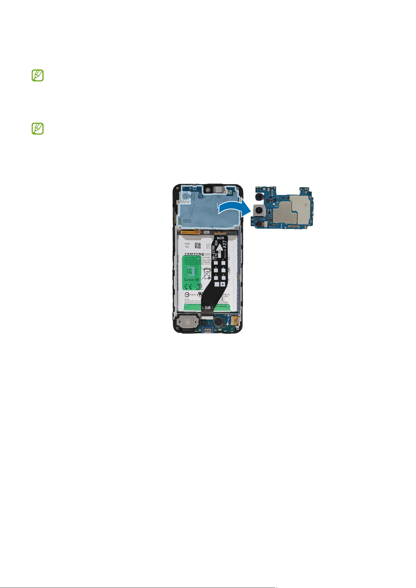
1 Check for the disassembly steps of the Rear Camera and completely separate up to
the main board module.
Disassembly and Assembly
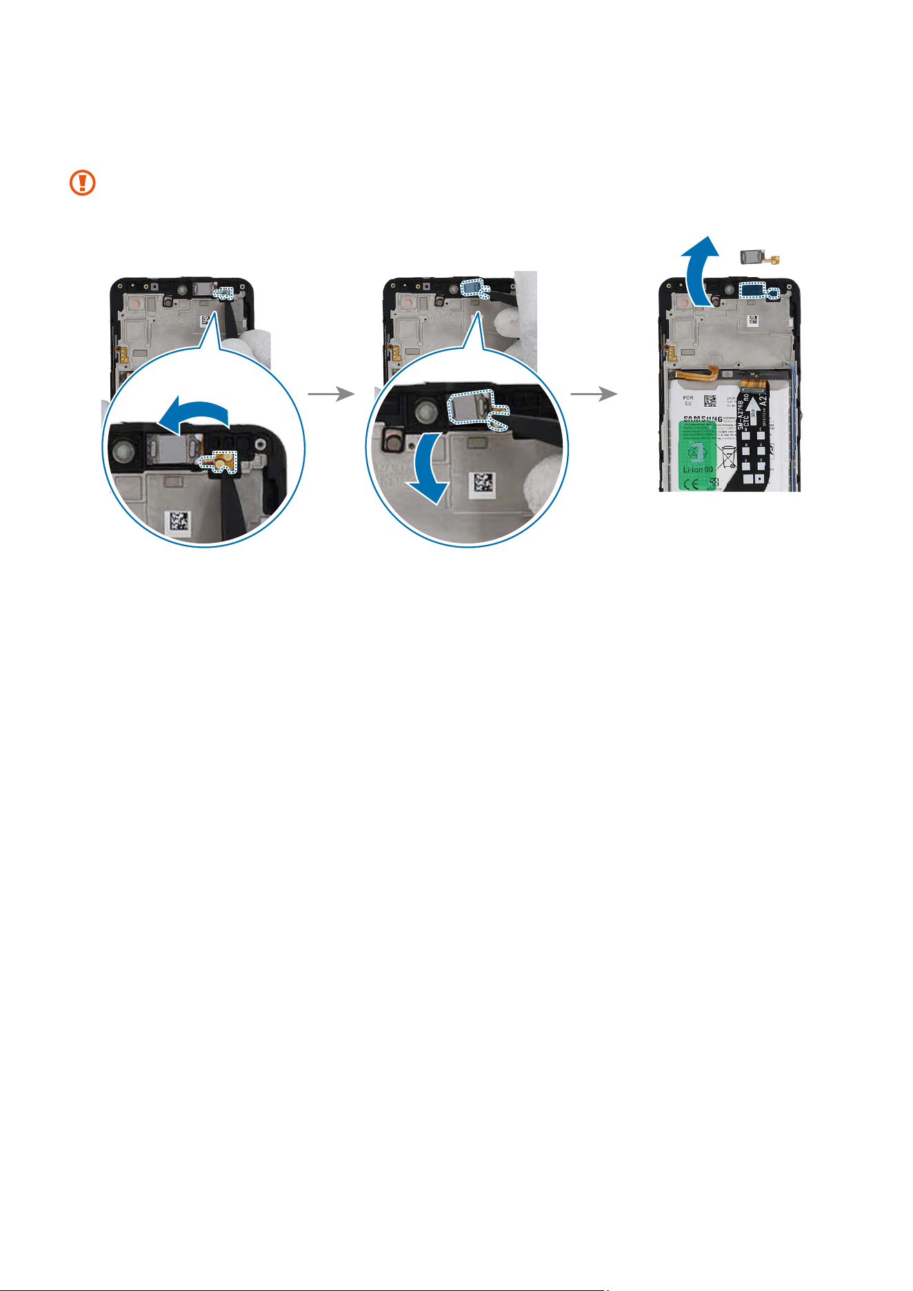
94
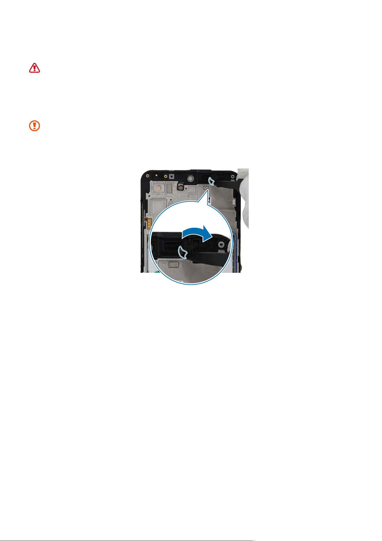
2 Using the tweezers, lift up on the separator groove of the speaker on the screen
module and remove it carefully.
Be careful not to damage the speaker.
Disassembly and Assembly
95
Reassembly
Leaving screws inside the device may damage internal components, such as the
battery. When assembling, be extra careful not to leave any unassembled screws
inside the device.
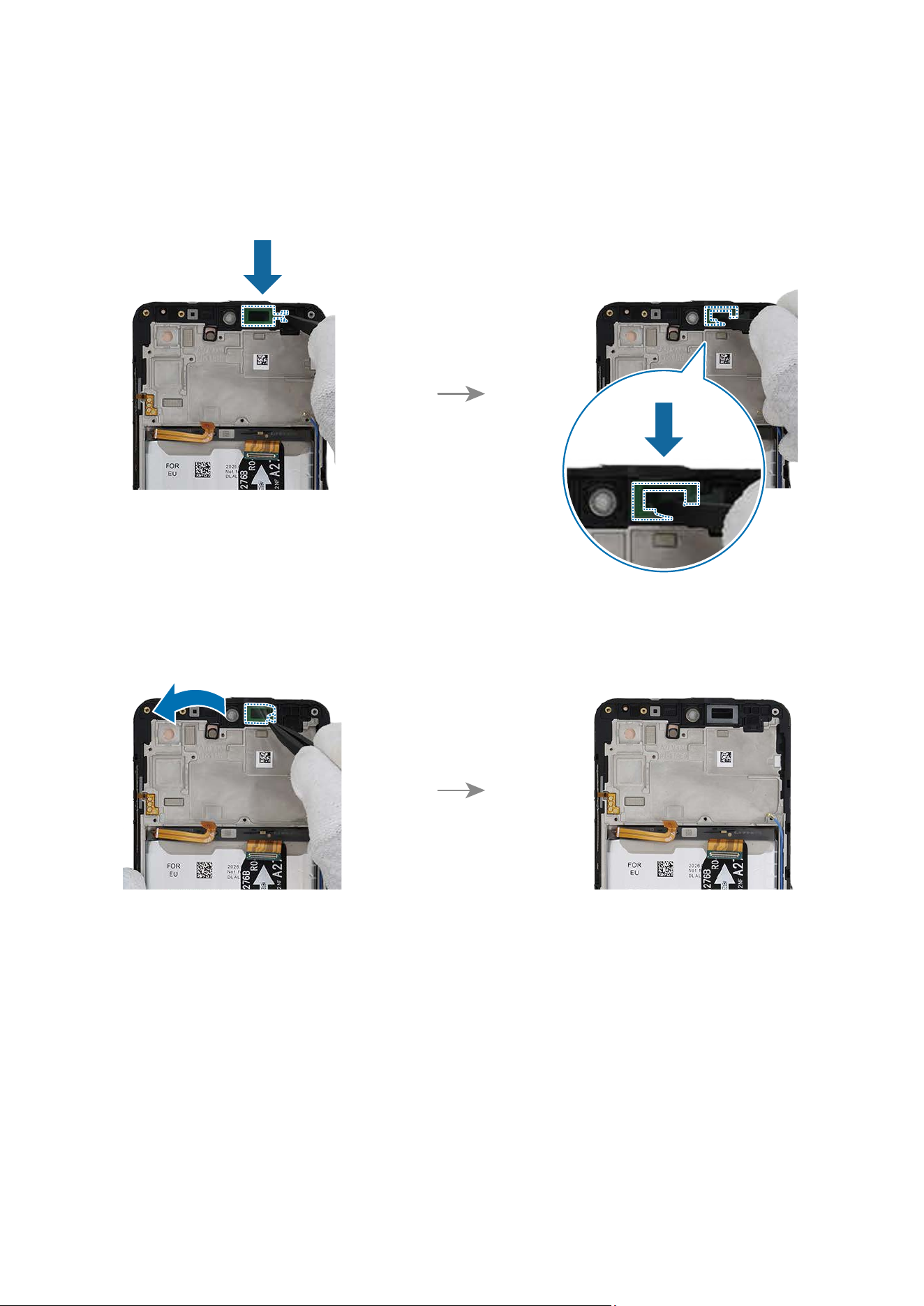
1 Using the tweezers, remove adhesive tape from where the top speaker was attached.
•
Make sure to remove any residual tapes attached to the position of the
separated speaker before reassembling the new speaker.
•
Be careful not to damage the near components.
Disassembly and Assembly
96
2 Using the tweezers, remove the release film of a new top speaker adhesive tape.
Align the outside shape of the tape with the top speaker position and attach it
accurately. Gently press down the tape with the tweezers so that the tape can be
attached well.
3 Using the tweezers, hold the protruding release film of the attached tape and
carefully remove it.
Disassembly and Assembly
97
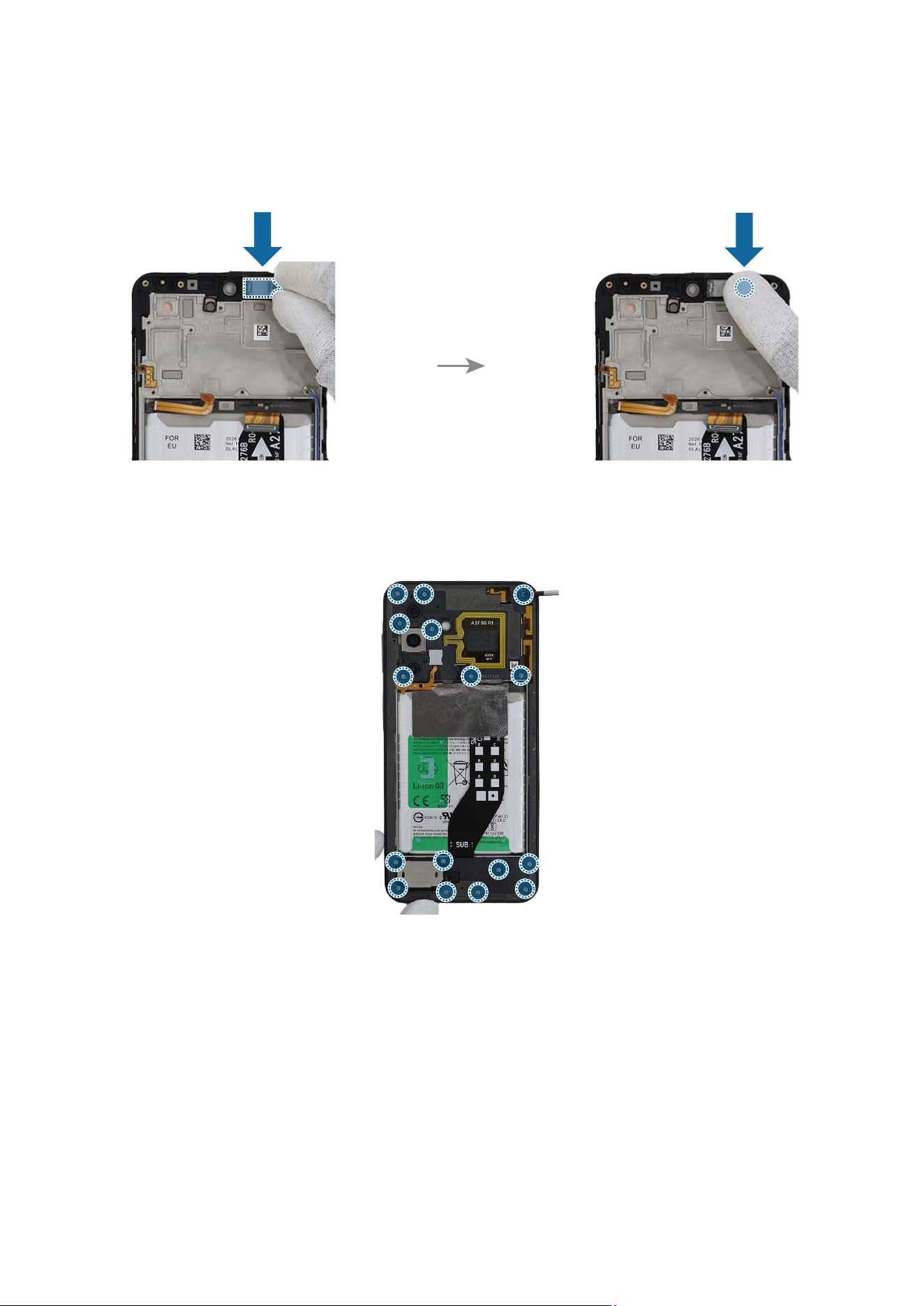
4 Remove the release film from the new top speaker and assemble the speaker to the
exact position of the screen module. Press the top speaker with your fingers softly so
that the speaker can be assembled well.
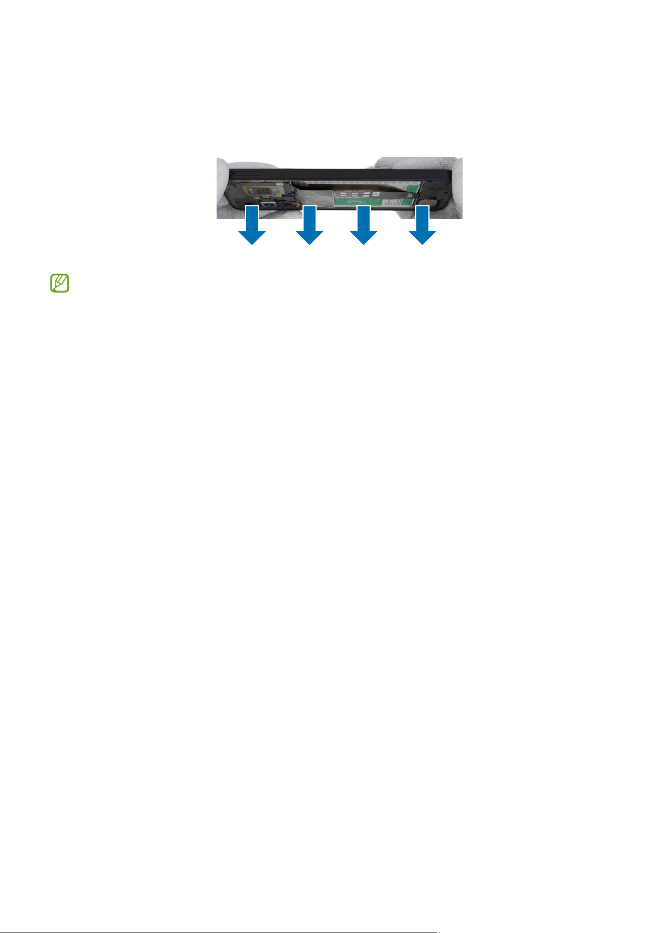
5 Check for the reassembly steps of the Front Camera and completely reassemble the
bracket.
Disassembly and Assembly
98
6 Check carefully with your fingers to see if there are any screws or other foreign
substances inside the device (battery, PBA, cable, etc.). Shake the device lightly with
the back of the device facing down to remove any remaining screws.
Reassemble the Back Cover and SIM Card Tray to complete assembly.
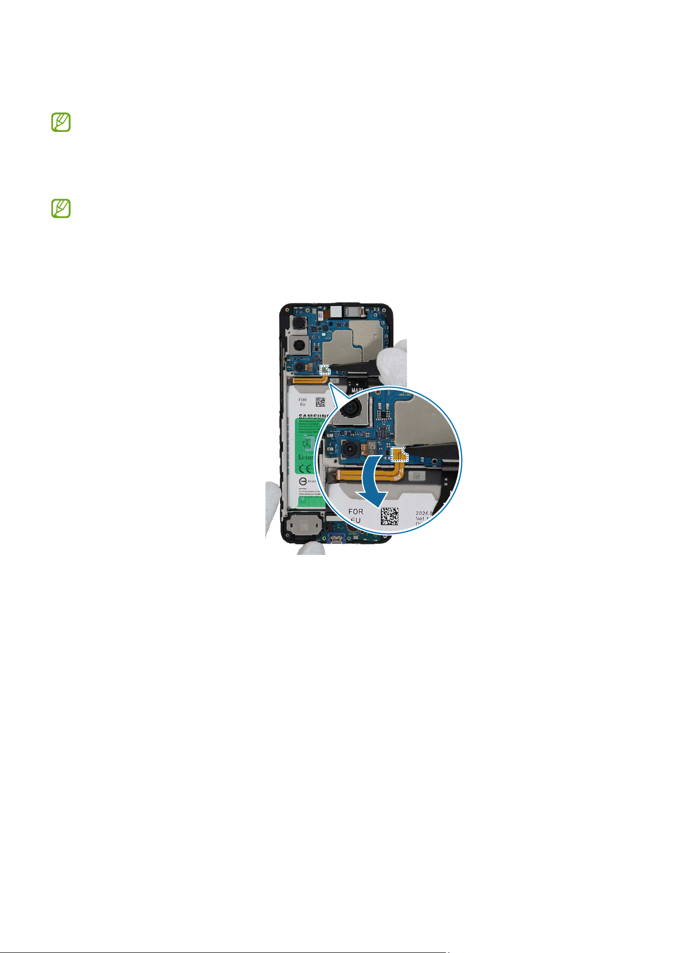
Disassembly and Assembly
99
Bottom Speaker
The bottom speaker is already built into the screen module. Disassemble the
speaker only if the speaker itself requires repairs.
Disassembly
Remove the SIM Card Tray and Back Cover first before you begin.
1 Check for the disassembly steps of the Front Camera and completely separate the
battery connector.
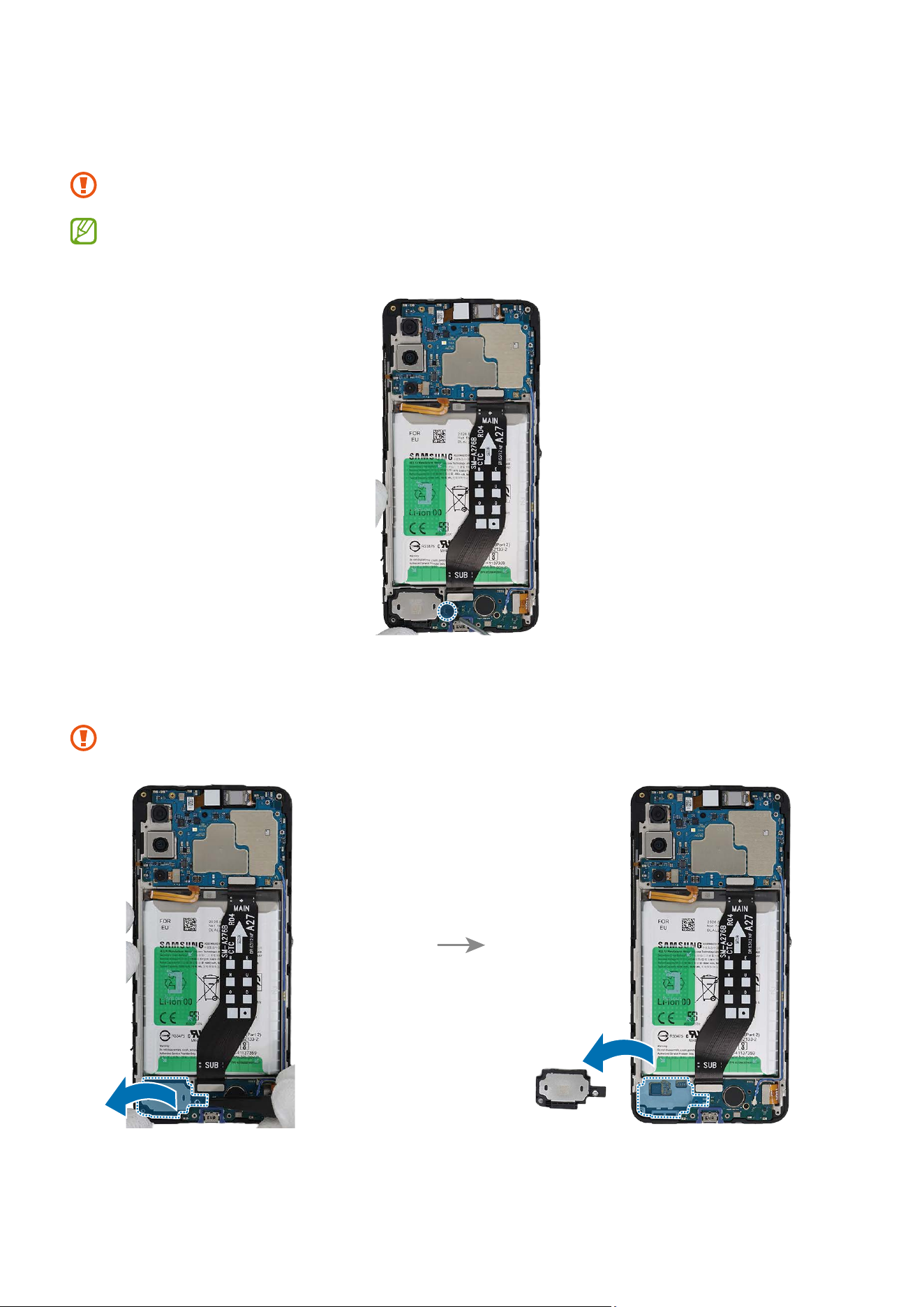
Disassembly and Assembly
100
2 Check the 1 screw on the bottom speaker and remove it using a cross-head
screwdriver.
Be careful not to damage the main board and near components.
Check the number of screws that have been removed, and store them carefully to
make sure that no unassembled screws are left inside the device during assembly.
3 Using the tweezers, lift up on the separator groove of the bottom speaker and remove
it carefully.
Be careful not to damage the near components.
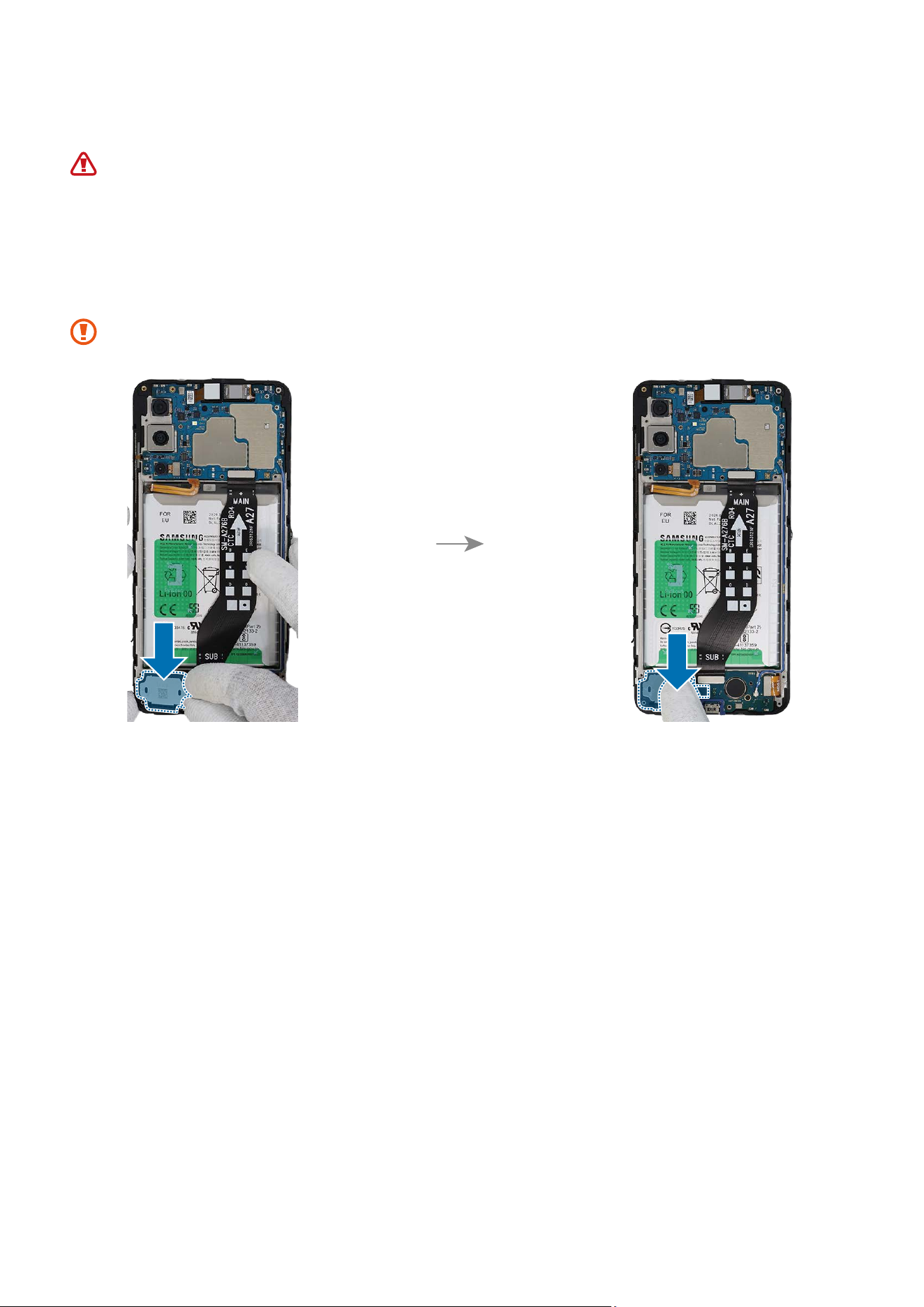
Disassembly and Assembly
101
Reassembly
Leaving screws inside the device may damage internal components, such as the
battery. When assembling, be extra careful not to leave any unassembled screws
inside the device.
1 Using the tweezers or your fingers, position the new bottom speaker in the correct
location and gently press it down to secure it in place.
Be careful not to damage the charging port and near components.
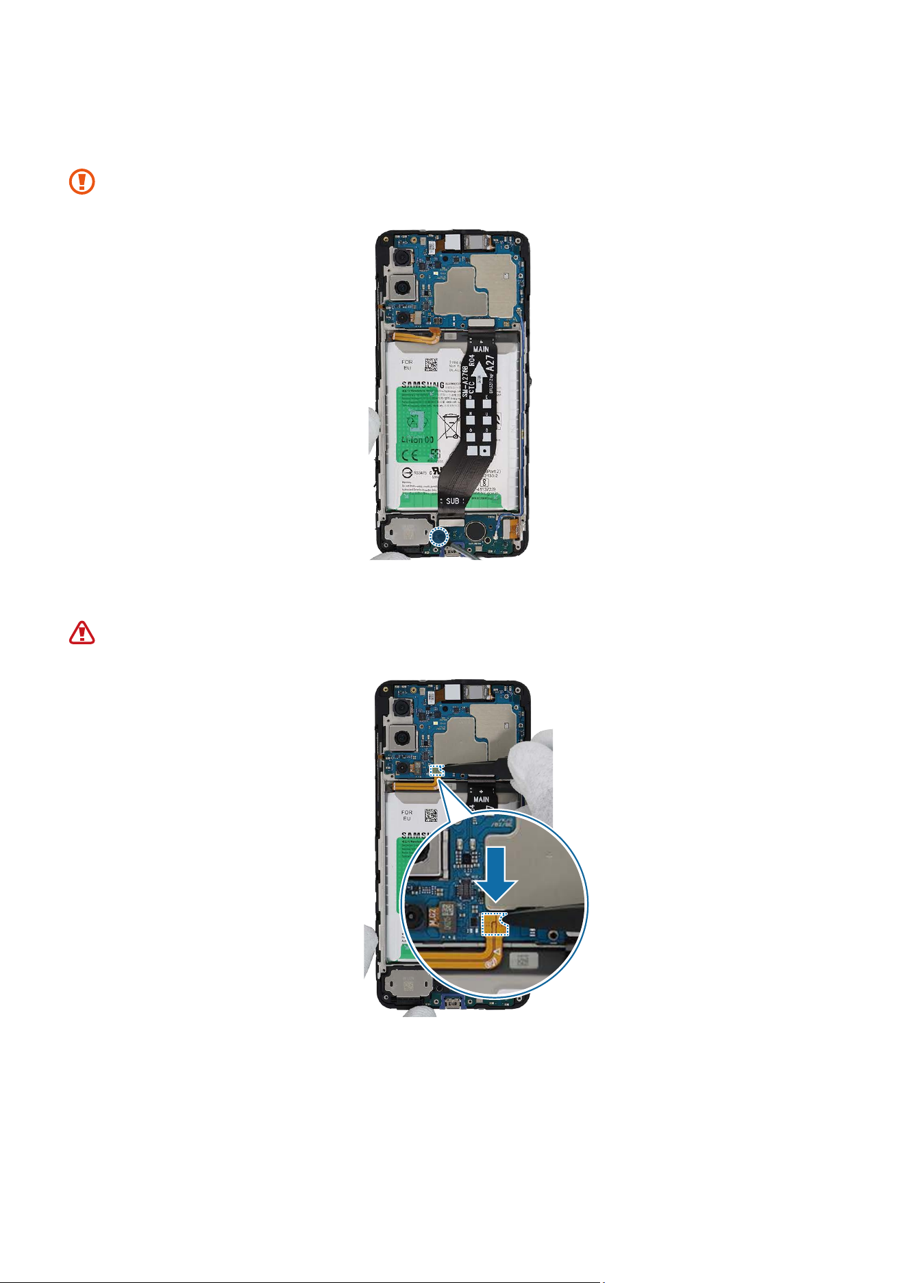
Disassembly and Assembly
102
2 Check the screw 3637 (1 ea) on the bottom speaker and fasten it using a cross-head
screwdriver.
Be careful not to damage the charging port and the near components.
3 Connect the battery connector to the main board.
Be careful not to damage the battery.
Disassembly and Assembly
103
4 Check for the reassembly steps of the Front Camera and completely reassemble the
bracket.
5 Check carefully with your fingers to see if there are any screws or other foreign
substances inside the device (battery, PBA, cable, etc.). Shake the device lightly with
the back of the device facing down to remove any remaining screws.
Reassemble the Back Cover and SIM Card Tray to complete assembly.
Disassembly and Assembly
104
Volume Button
Disassembly
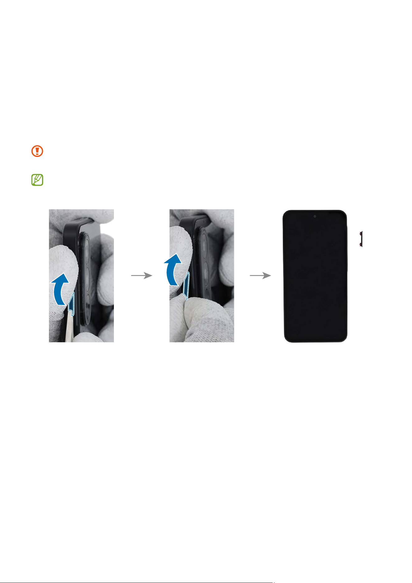
To remove the Volume button, lightly press one end of the button with your fingers so
that the other end protrudes. Push the tip of the protruding button up carefully with a
round-tip metal tweezer and lift it up until you can grab it with your fingers. Grab the
button with your fingers and pull it out carefully from the device.
When holding the buttons with a tweezer, be very careful not to damage or scratch
the device.
If you have trouble separating the buttons with your tweezers, please try using a
sharper and thinner tool.
Disassembly and Assembly
105
Reassembly
Leaving screws inside the device may damage internal components, such as the
battery. When assembling, be extra careful not to leave any unassembled screws
inside the device.
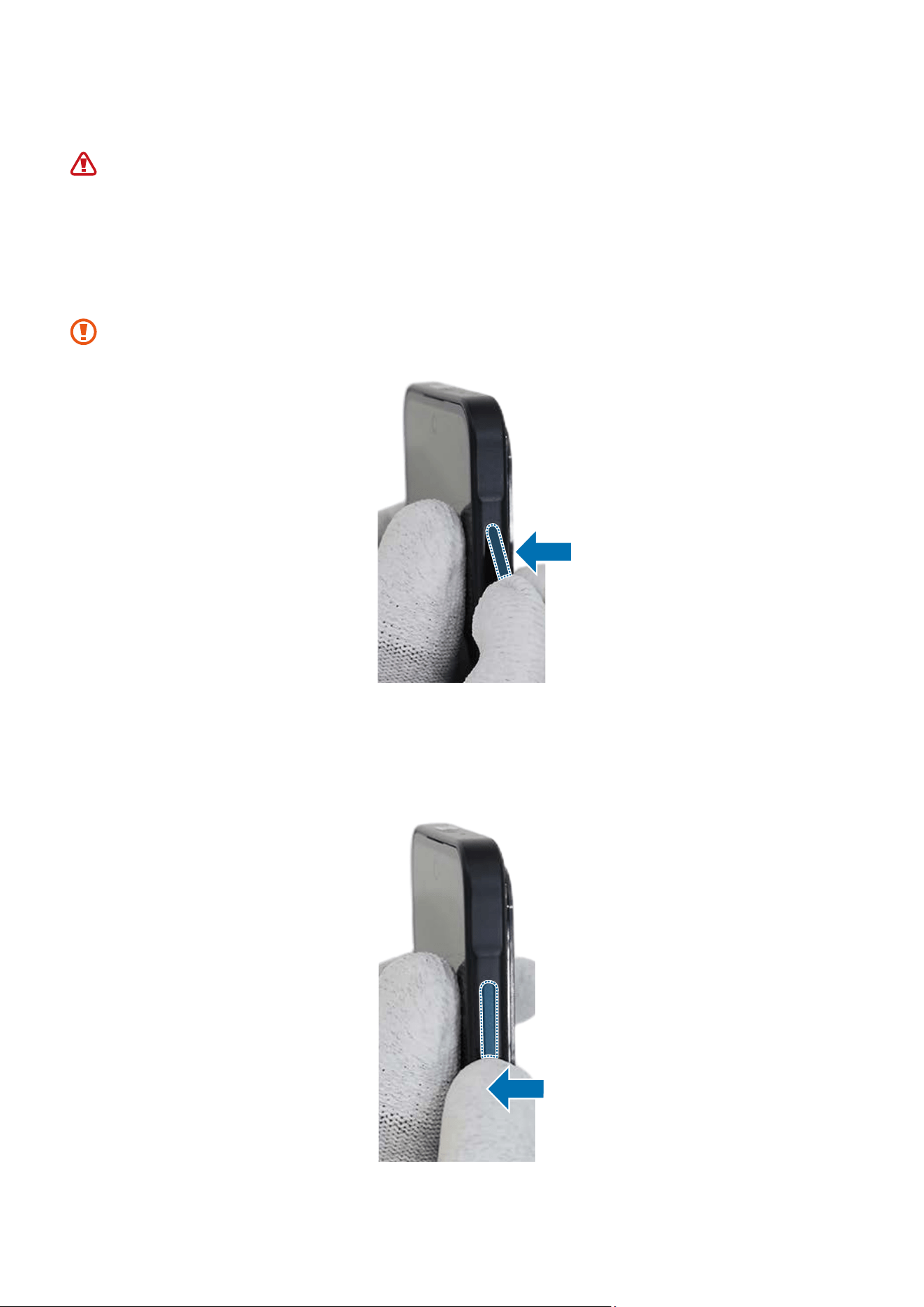
1 Remove the release film of the new Volume button. Use your fingers to grab the
volume button and insert the button on the slot carefully.
Be careful not to damage the button and device.
2 Press down the Volume button softly and evenly so that the button can be completely
assembled. Press the Volume button to make sure it clicks. It should have the same
sound and feel as before disassembly.
Disassembly and Assembly
106
Side Button (Fingerprint Recognition Sensor)
The Side button has a built-in fingerprint recognition sensor. Thus, it cannot be
removed directly from outside.
Disassembly
Remove the SIM Card Tray and Back Cover first before you begin.
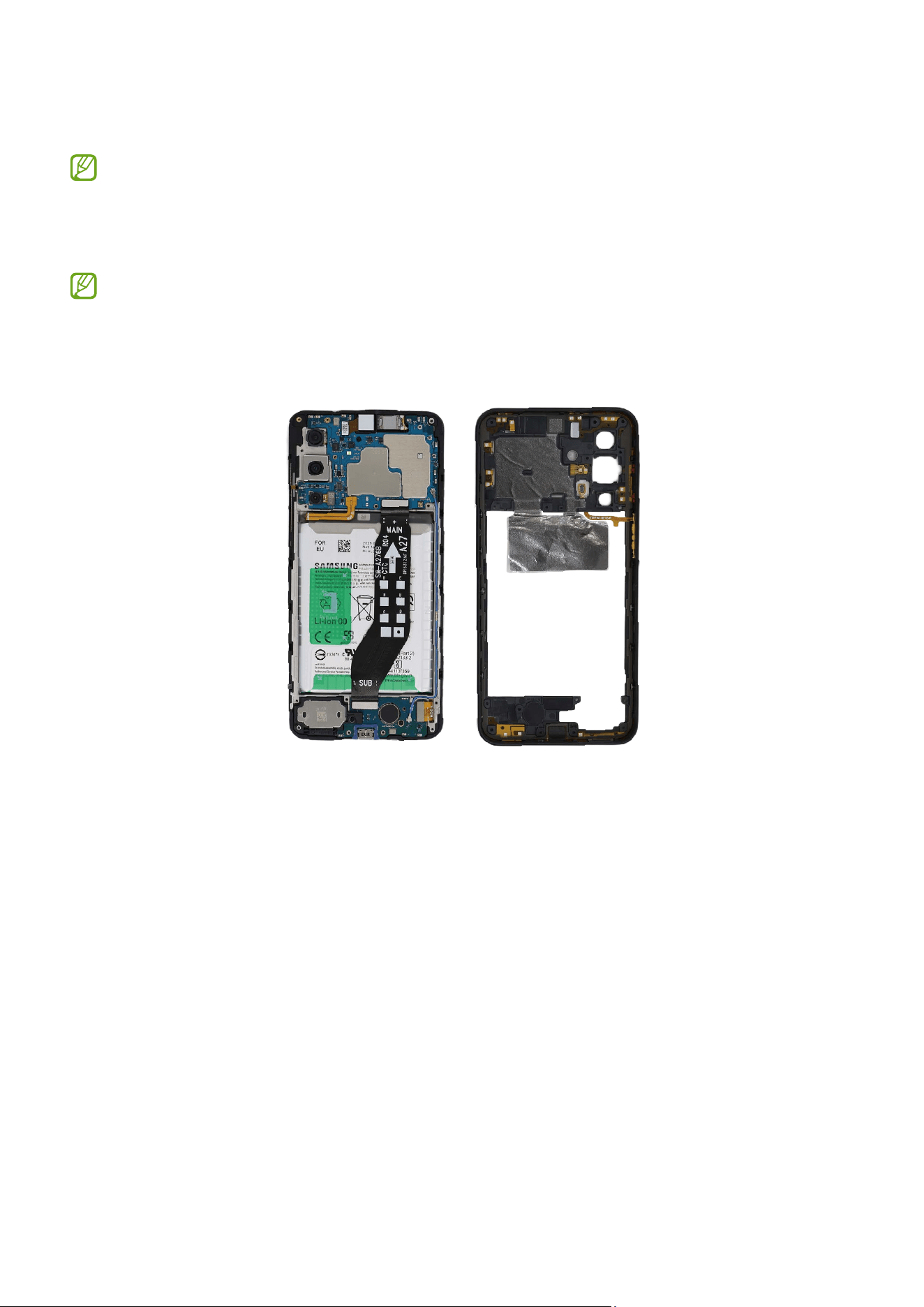
1 Check for the disassembly steps of the Front Camera and completely separate the
bracket.
Disassembly and Assembly
107
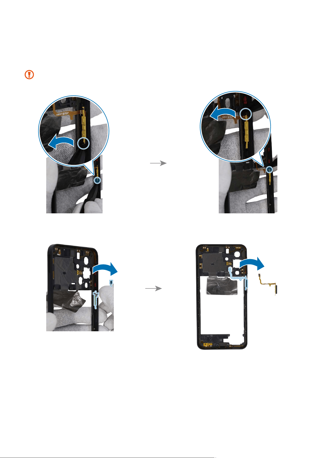
2 Using the tweezers, grab the rubber for Side button module and separate each end of
it carefully. Using your fingers, grab the Side button module and separate it from the
rear bracket.
Be careful not to damage or scratch the bracket.
Disassembly and Assembly
108
Reassembly
Leaving screws inside the device may damage internal components, such as the
battery. When assembling, be extra careful not to leave any unassembled screws
inside the device.
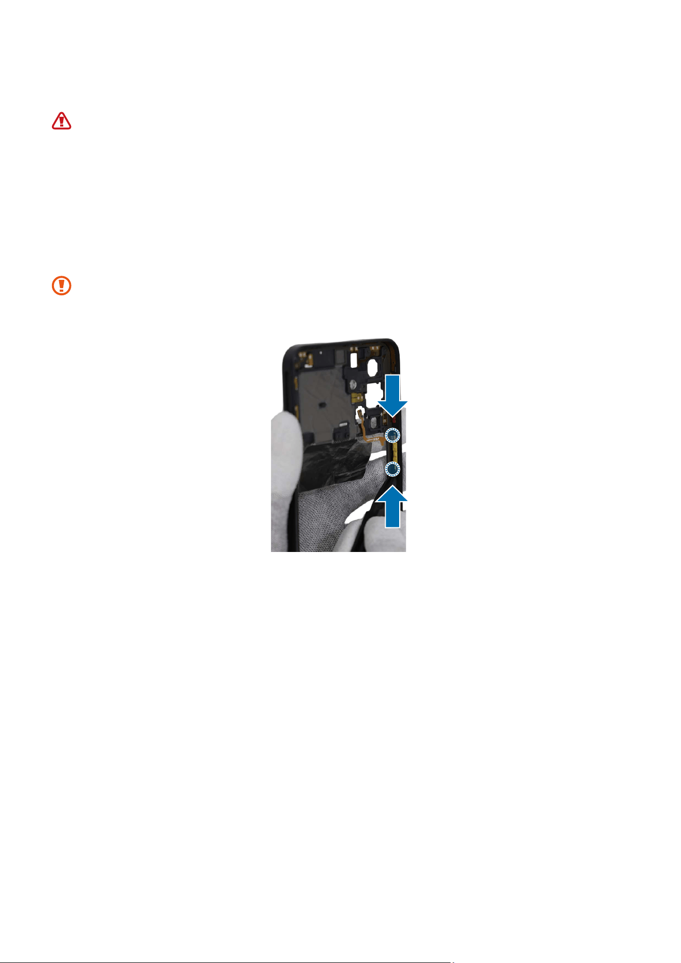
1 Remove the release film from new side button module. Using the tweezers, grab the
side button module and insert it to the rear bracket carefully. Using the tweezers,
grab the rubber for side button module and assemble each end of it exactly to the
rear bracket.
•
Be careful not to damage or scratch the bracket.
•
Be careful not to damage the buttons.
Disassembly and Assembly
109
2 Check for the reassembly steps of the Front Camera and completely reassemble the
bracket.
3 Check carefully with your fingers to see if there are any screws or other foreign
substances inside the device (battery, PBA, cable, etc.). Shake the device lightly with
the back of the device facing down to remove any remaining screws.
Reassemble the Back Cover and SIM Card Tray to complete assembly.
Disassembly and Assembly
111
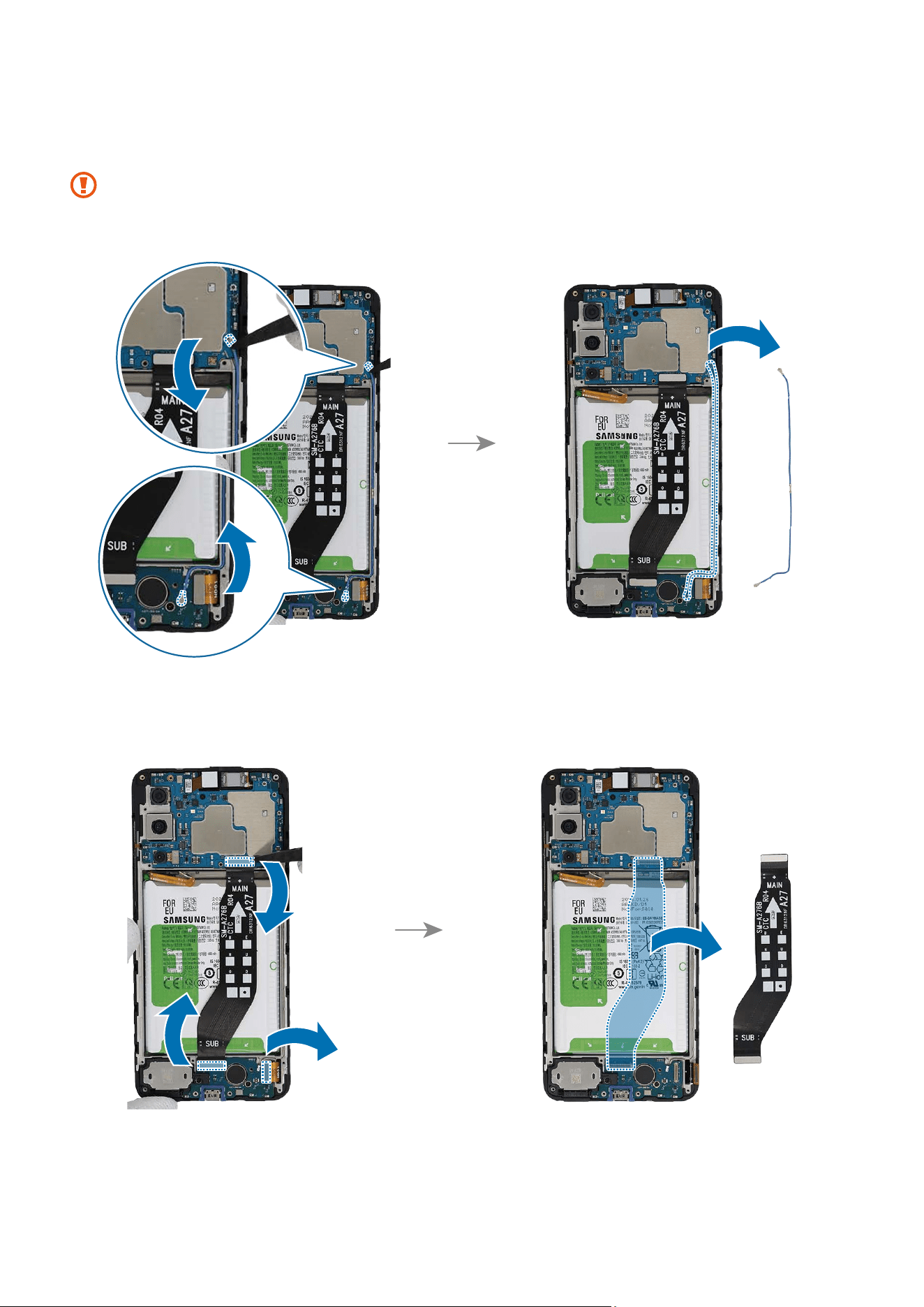
2 Using the tweezers, disconnect the 2 connectors from the device and remove the
coaxial cable completely.
•
When removing the connectors, be careful not to damage the cable.
•
Be careful not to damage the near components.
3 Using the tweezers, disconnect the 3 connectors and remove the flex cable
completely.
Disassembly and Assembly
112
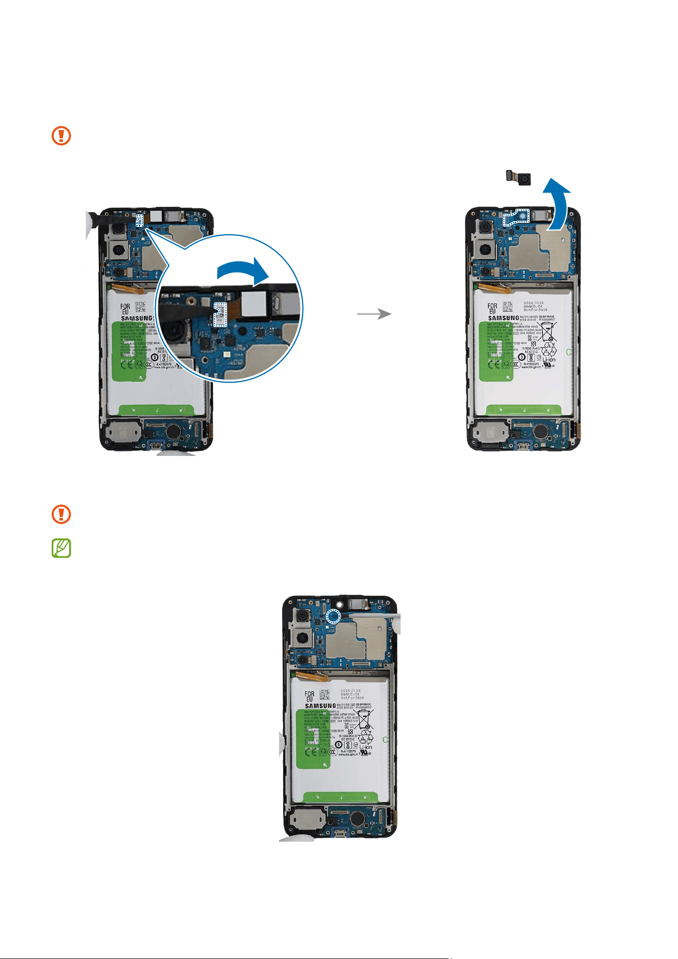
4 Using the tweezers, separate the front camera connector from the main board and
remove the front camera carefully from the device. Leave the camera lens facing up.
Be careful not to touch the camera lens while removing the camera.
5 Check the 1 screw on the main board and remove it using a cross-head screwdriver.
Be careful not to damage the main board and near components.
Check the number of screws that have been removed, and store them carefully to
make sure that no unassembled screws are left inside the device during assembly.
Disassembly and Assembly
113
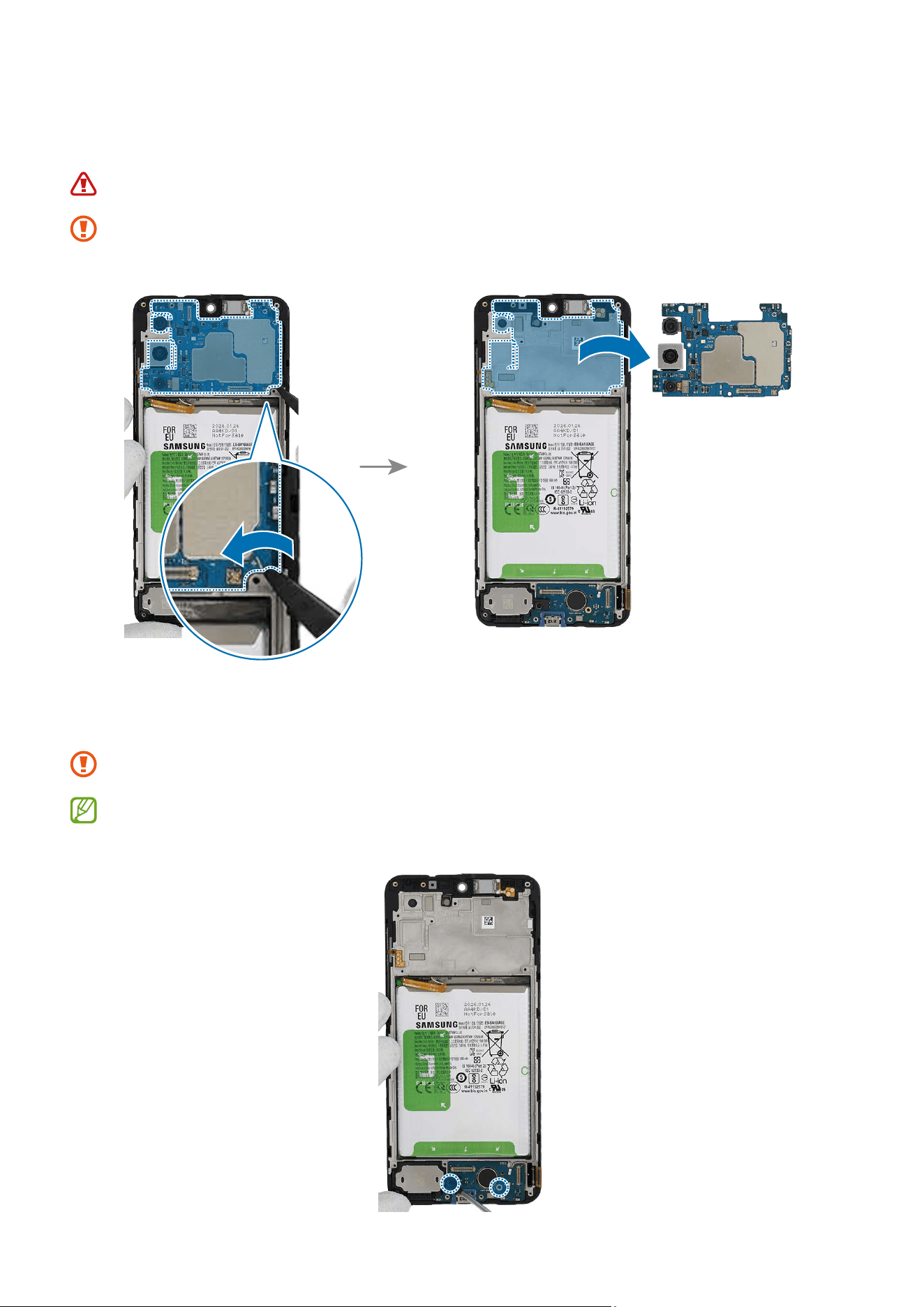
6 Using the tweezers, lift up on the separator groove of the main board and remove it
carefully.
Be careful not to damage the battery.
The FPCB cables have to be positioned outside so as not to interfere when
disassembling the main board.
7 Check the screws at the 2 different points and remove them using a cross-head
screwdriver.
Be careful not to damage the near components.
Check the number of screws that have been removed, and store them carefully to
make sure that no unassembled screws are left inside the device during assembly.
Disassembly and Assembly
114
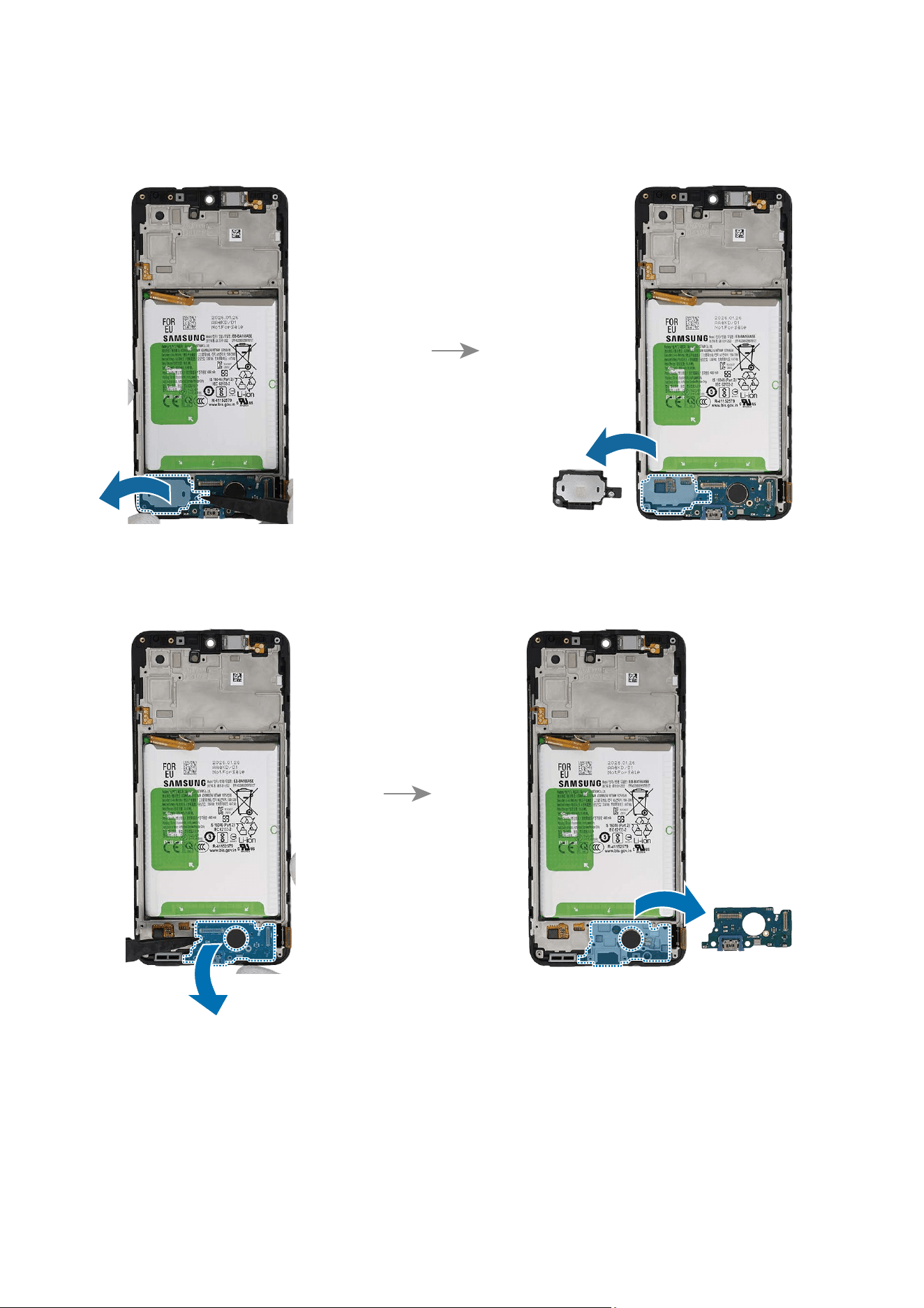
8 Using the tweezers, lift up on the separator groove of the bottom speaker and remove
it carefully.
9 And then, lift up on the separator groove of the charging port module and remove it
carefully.
Disassembly and Assembly
115
10
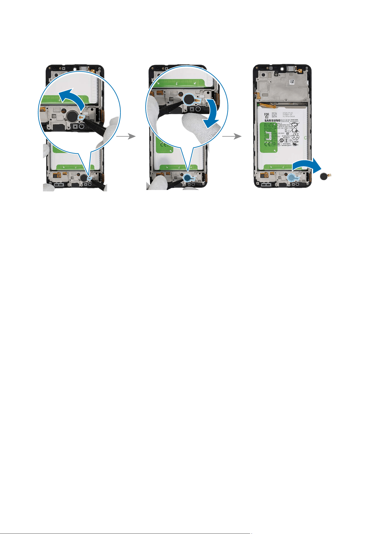
Lastly, lift up on the separator groove of the vibrator motor and remove it carefully.
Disassembly and Assembly
116
Reassembly
Leaving screws inside the device may damage internal components, such as the
battery. When assembling, be extra careful not to leave any unassembled screws
inside the device.
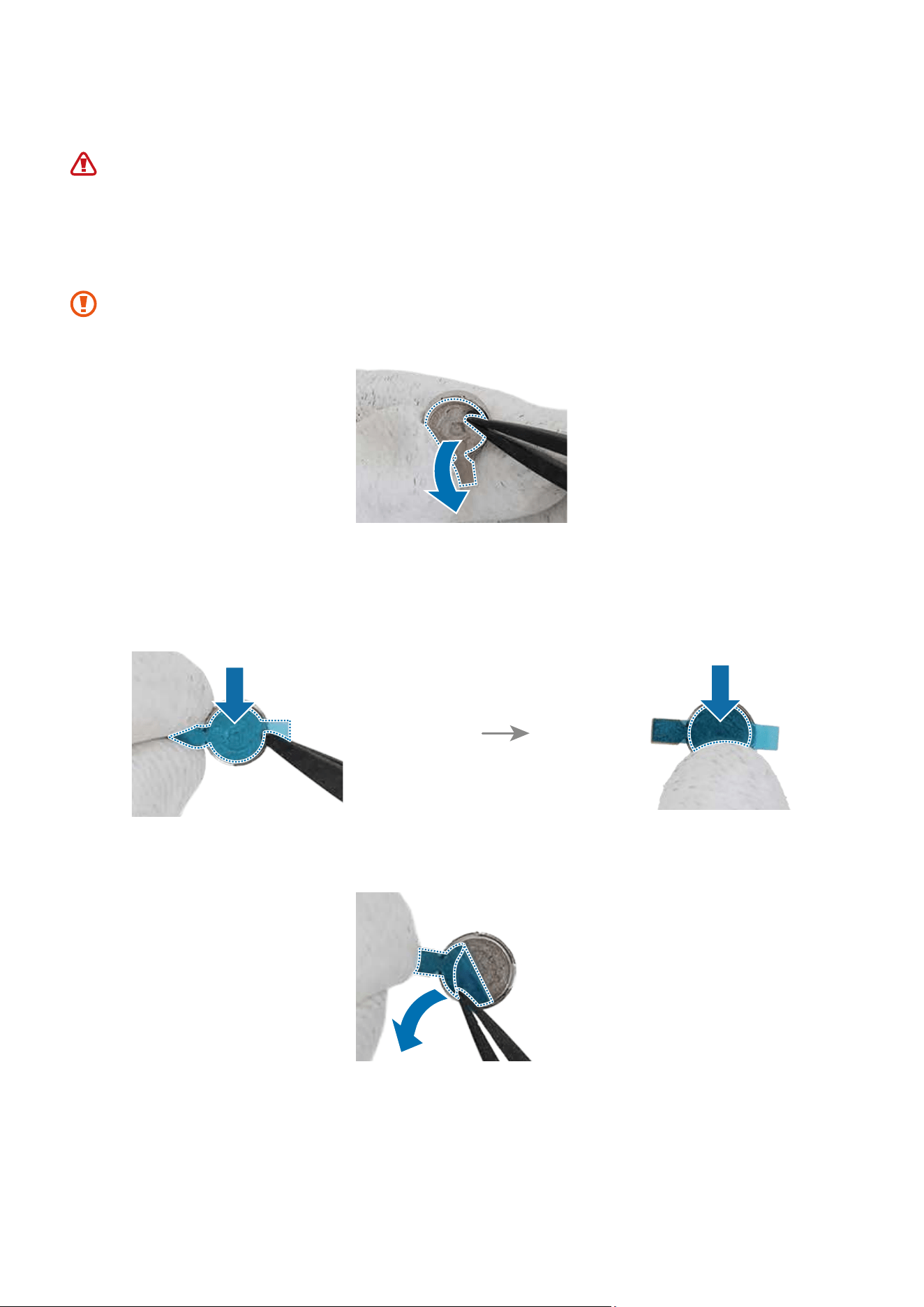
1 Remove the adhesive tape on the bottom of the vibrator motor.
Be careful not to damage the vibrator motor.
2 Remove the clear film from new vibrator motor adhesive tape and apply it to the
bottom of the vibrator motor. Gently press down the tape with your fingers so that
the tape can be attached well.
3 Remove the release film from the adhesive tape.
Disassembly and Assembly
117
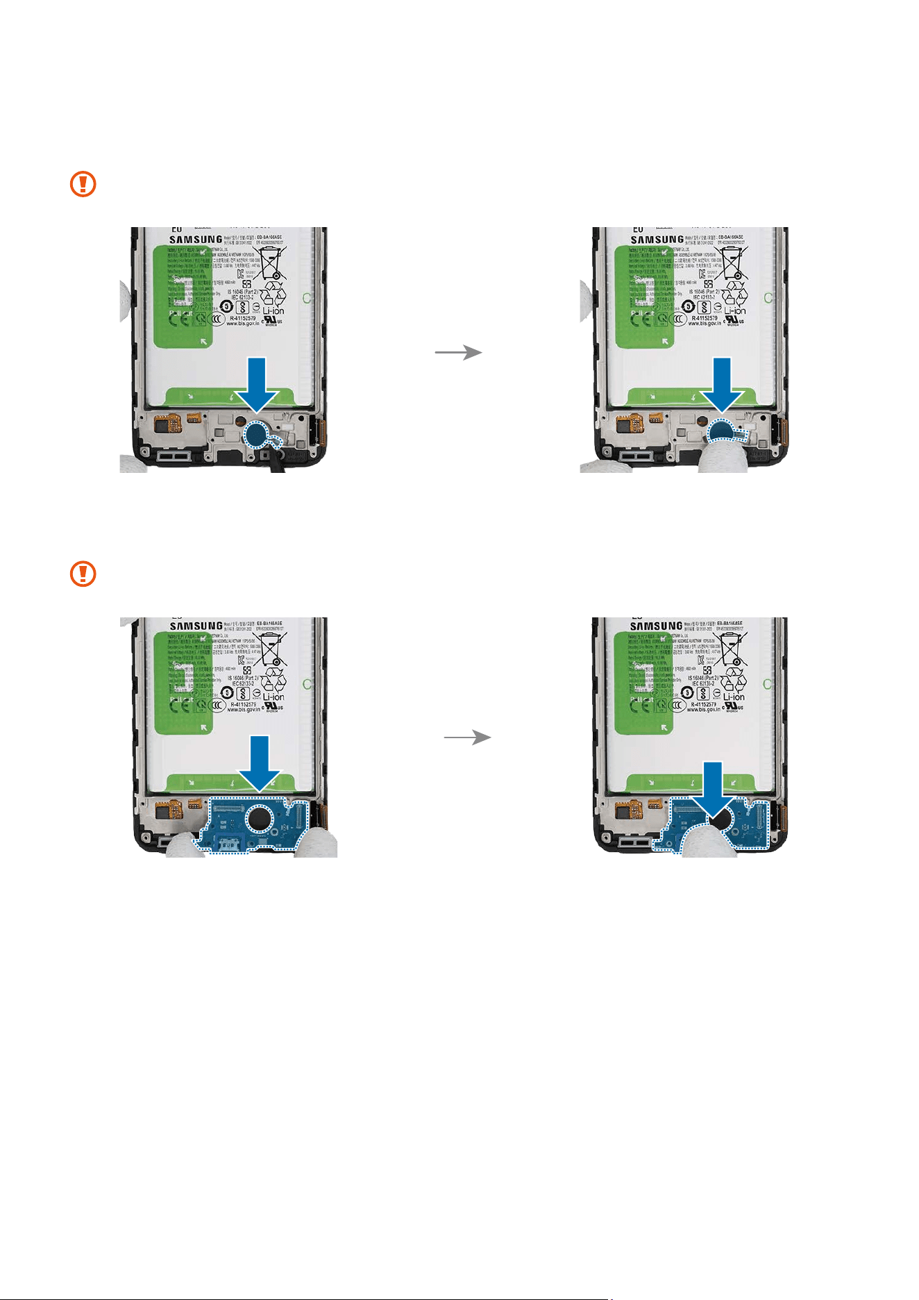
4 Using the tweezers, assemble the vibrator motor to the exact position of the new
screen module and press it with fingers softly.
Be careful not to damage the vibrator motor.
5 Insert the charging port module to the bottom device frame of device and press down
on it in its position smoothly.
Be careful not to damage the charging port module.
Disassembly and Assembly
118
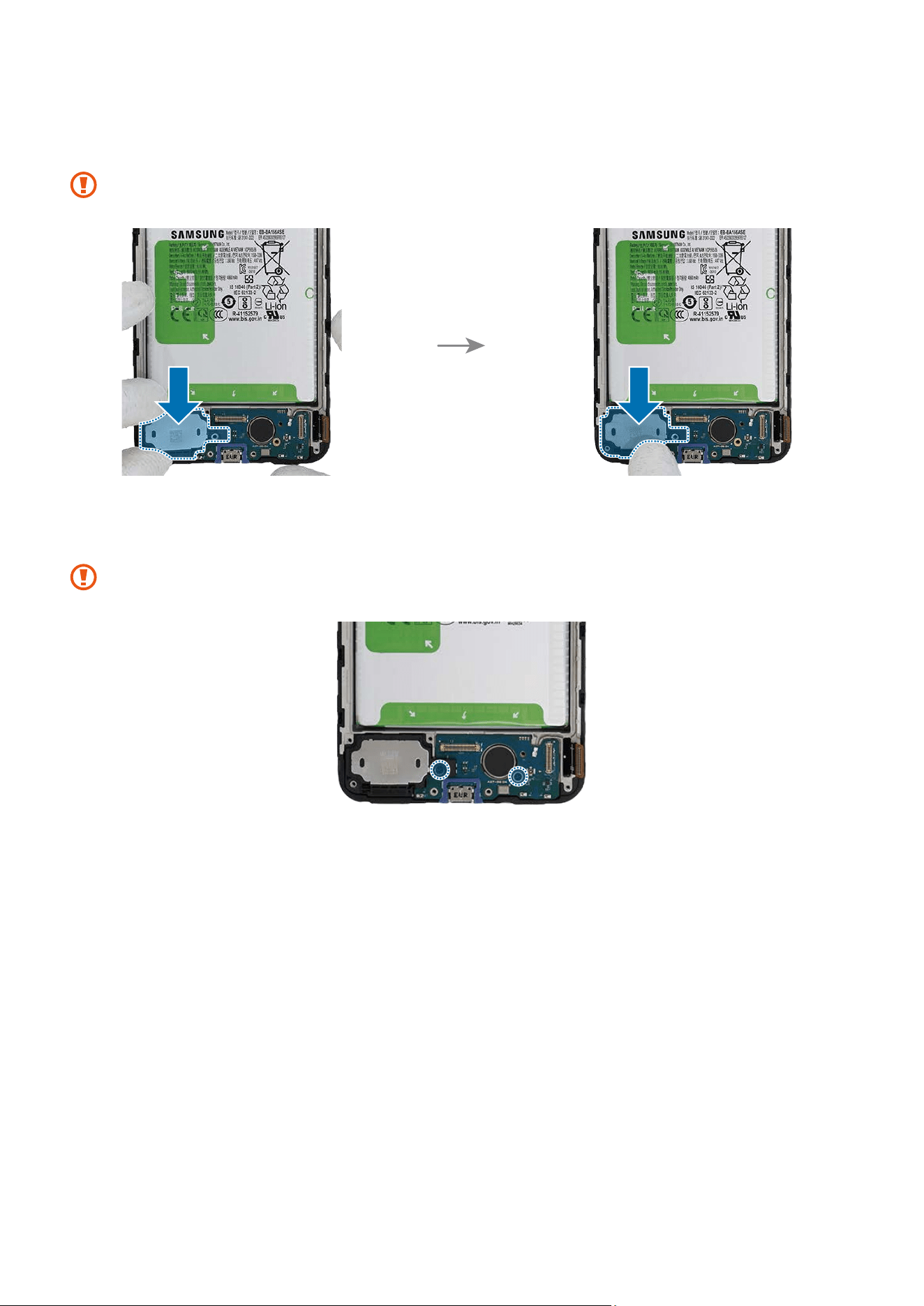
6 Insert the bottom speaker to the bottom metal frame of device and press down on it
in its position smoothly.
Be careful not to damage the bottom speaker.
7 Check the screw 3637 (2 ea) at the 2 different points on the charging port module and
fasten them using a cross-head screwdriver.
Be careful not to damage the charging port and the near components.
Disassembly and Assembly
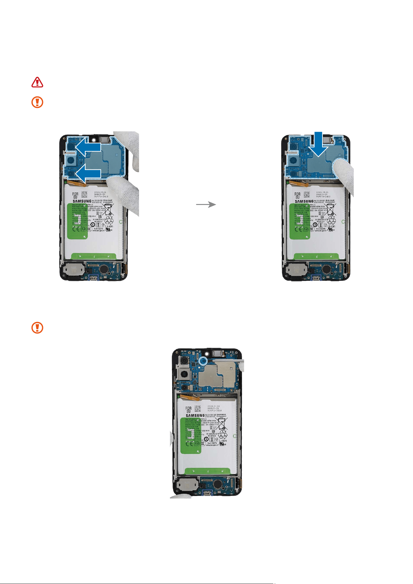
119
8 Align the main board onto the device frame. After attaching the left part of the main
board on the metal frame, assemble the right part.
Be careful not to damage the battery.
The FPCB cables and coaxial cable have to be positioned outside so as not to
interfere when assembling the main board.
9 Check the screw 3637 (1 ea) on the main board and fasten it using a cross-head
screwdriver.
Be careful not to damage the near components.
Disassembly and Assembly
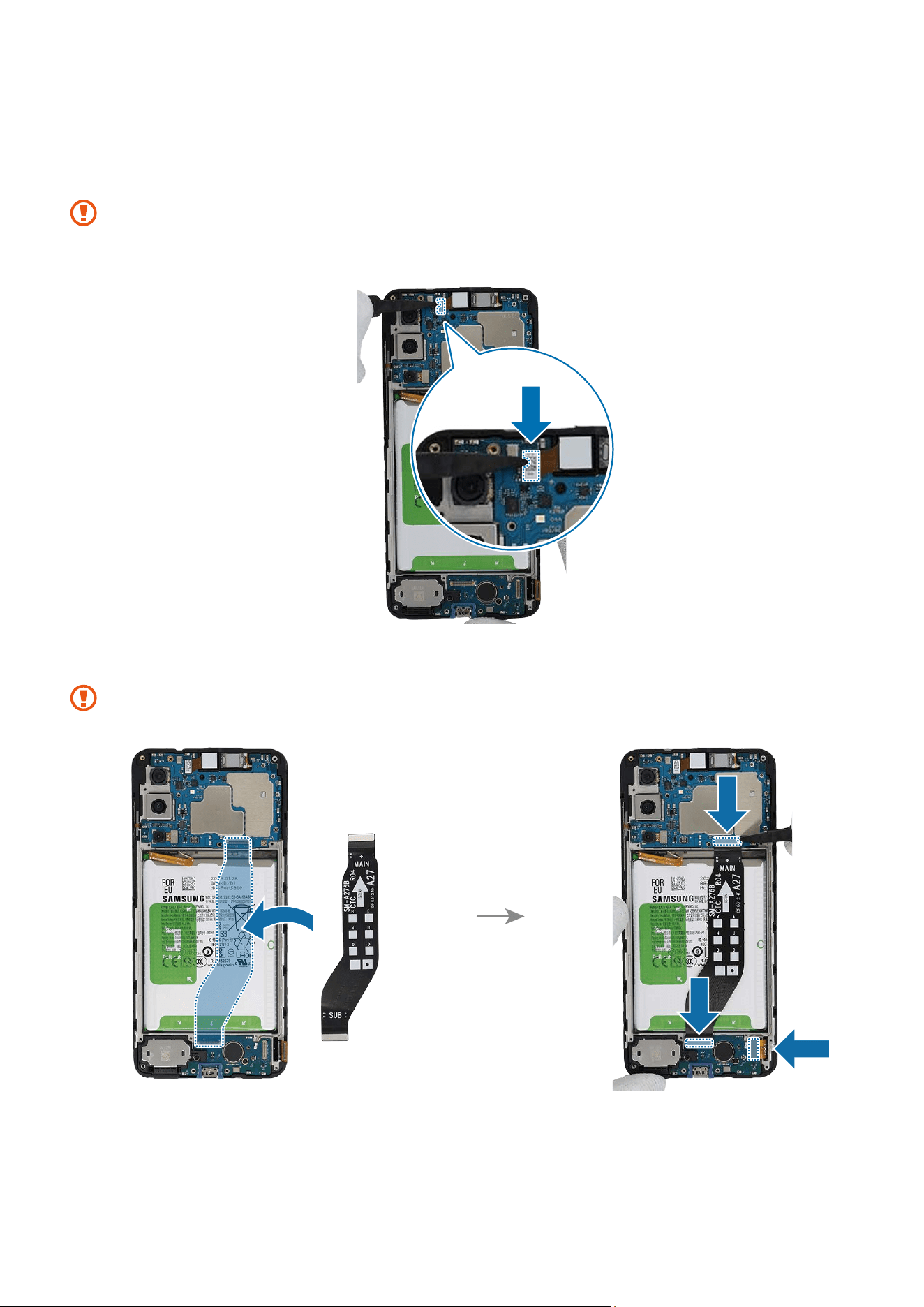
120
10
Using the tweezers or your fingers, place the new front camera in the camera hole so
that the lens faces forward and gently insert. Then, connect the camera connector
carefully on the main board.
•
Be careful not to damage the camera lens and the near components.
•
Be careful not to damage the main board.
11
Place the flex cable to the device frame and connect the 3 connectors carefully.
When connecting the connectors, be careful not to damage the cable.
Disassembly and Assembly
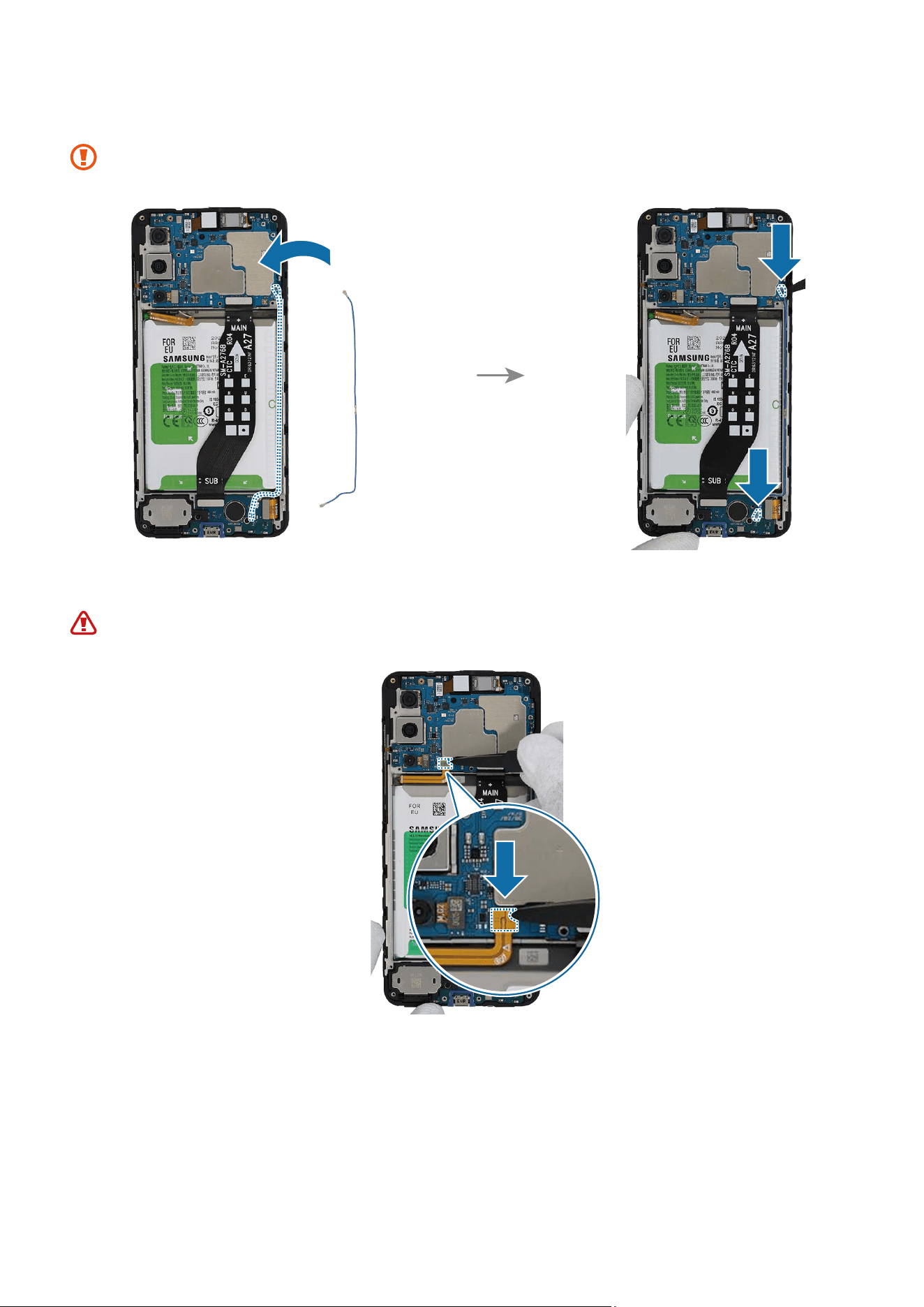
121
12
Place the coaxial cable to the device frame and connect the 2 connectors carefully.
When connecting the connectors, be careful not to damage the cable.
13
Connect the battery connector to the main board.
Be careful not to damage the battery.
Disassembly and Assembly
122
14
Check for the reassembly steps of the Front Camera and completely reassemble the
bracket.
15
Check carefully with your fingers to see if there are any screws or other foreign
substances inside the device (battery, PBA, cable, etc.). Shake the device lightly with
the back of the device facing down to remove any remaining screws.
Reassemble the Back Cover and SIM Card Tray to complete assembly.
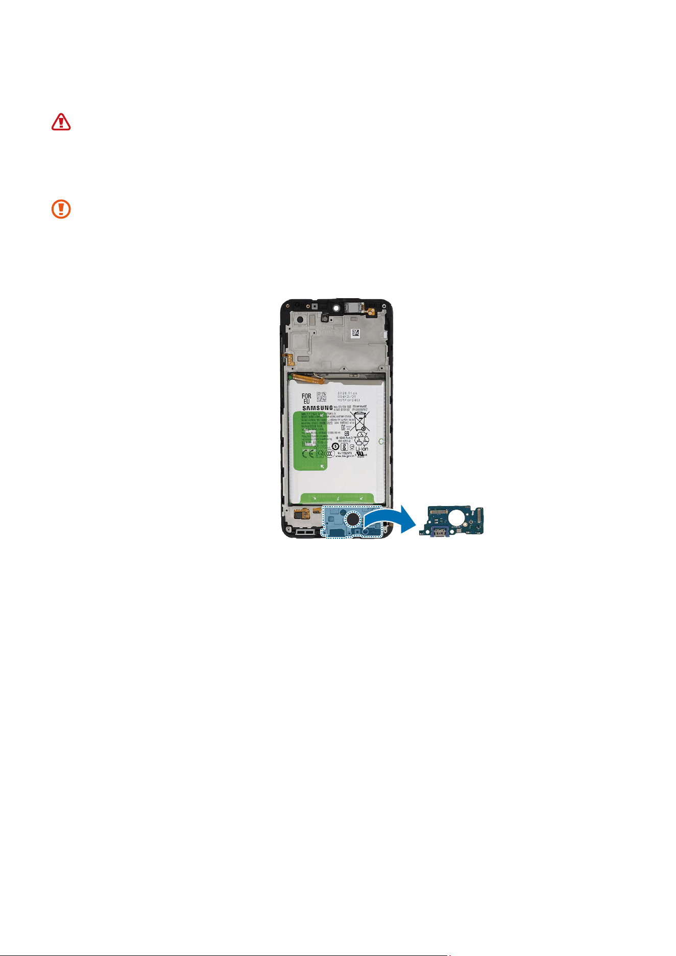
Disassembly and Assembly
123
Screen
The screen should be replaced only by the specialised technicians with the
knowledge and experience to repair electronic devices.
Disassembly
When removing the screen, ensure that the device is fixed on a flat surface.
1 Check for the disassembly steps of the Screen Module and completely separate up to
the charging port module.
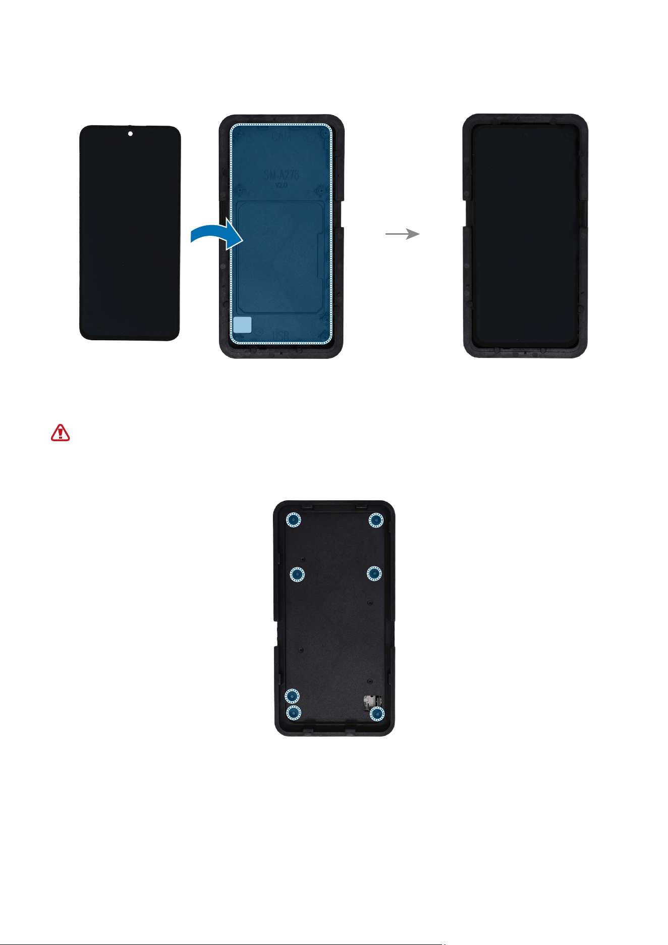
Disassembly and Assembly
124
2 Place the screen module in the correct position on the bottom press tray.
3 Secure with the 7 screws removed from the bracket into the screw holes on the back
of the bottom press tray using a cross-head screwdriver.
Leaving screws inside the device may damage internal components, such as the
battery. When assembling, be extra careful not to leave any unassembled screws
inside the device.
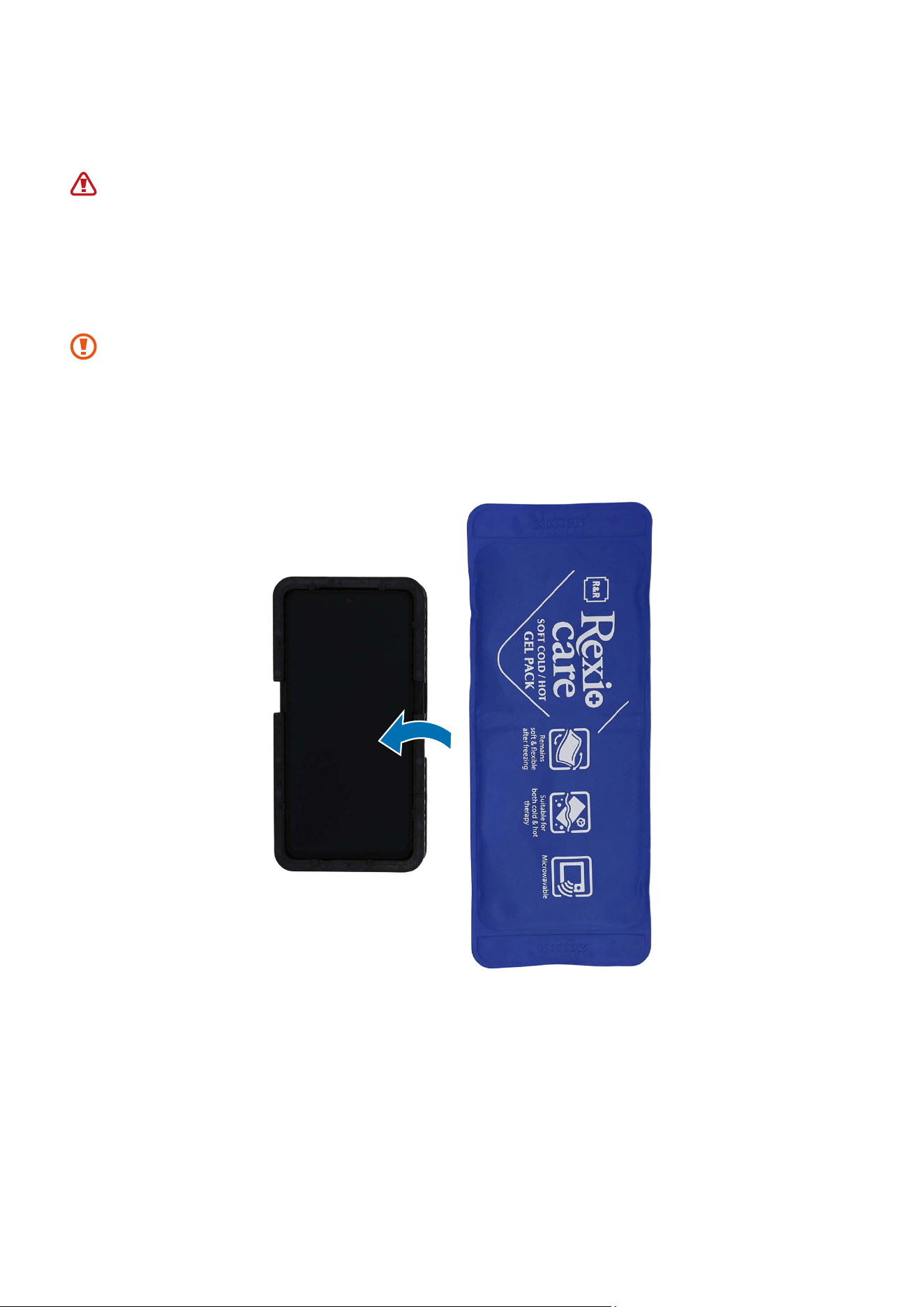
Disassembly and Assembly
125
4 Heat the microwaveable heating bag and apply it on the screen for 5 minutes to
soften the adhesive.
•
It is possible for the device or battery to be damaged by heat.
•
Do not heat the device in a microwave. Doing so could cause an explosion.
•
If your device’s glass breaks, the debris can cause injury to your hands or
other body parts. For your safety, attach an acrylic protective cover before
disassembling the device.
•
The recommended time for heating the bag is 50 seconds in a 1000 W
microwave and 70 seconds in a 700 W microwave. (Correct temperature for use:
55-65 ℃.) Follow the heating bag’s instructions for heating.
•
Be careful not to damage the device through excessive heat. (It is
recommended to disassemble the device in an area with temperature gauge.)
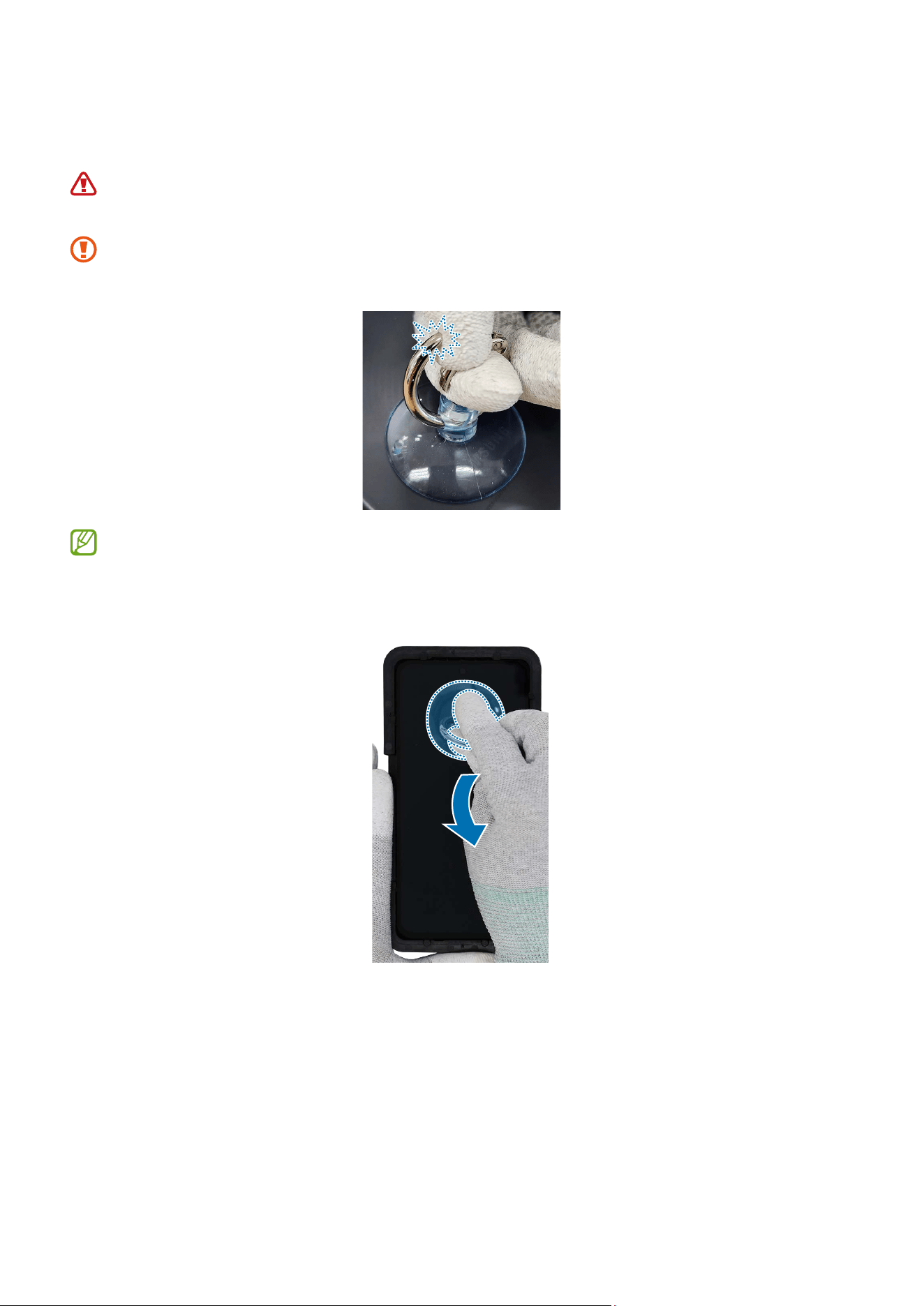
Disassembly and Assembly
126
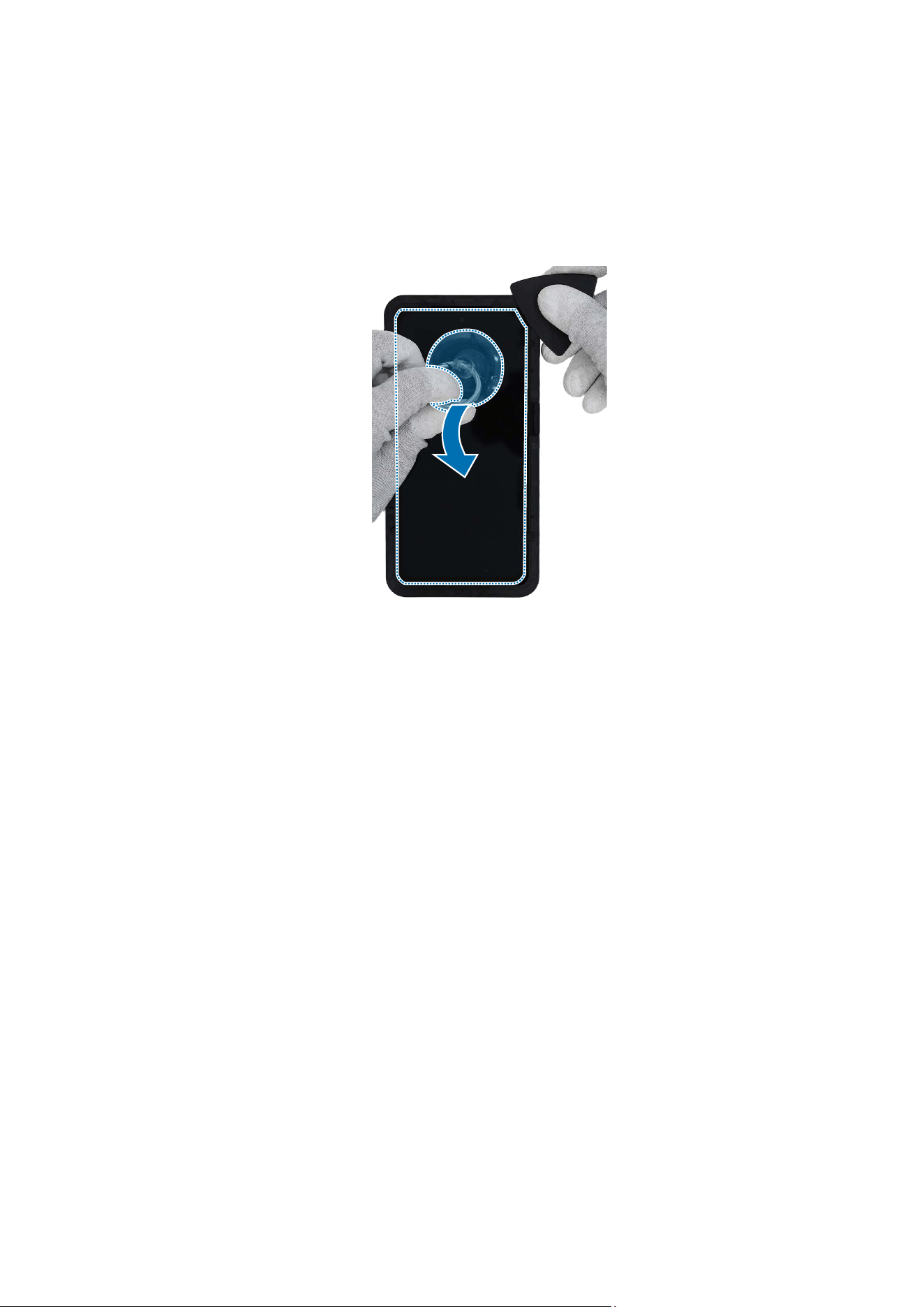
5 Place the suction cup in the centre of the top edge of the screen, and lift it upwards
carefully.
For separable handle suction cups, be careful not to injure yourself as the handle
can be parted during use.
Be careful that the suction cup does not adhere to the area where the tape or
sticker is attached.
If you have trouble creating a gap, heat the microwaveable heating bag
additionally, and apply it on the screen to further soften the adhesive. When
reheating, it should be heated no longer than 30 seconds.
Disassembly and Assembly
127
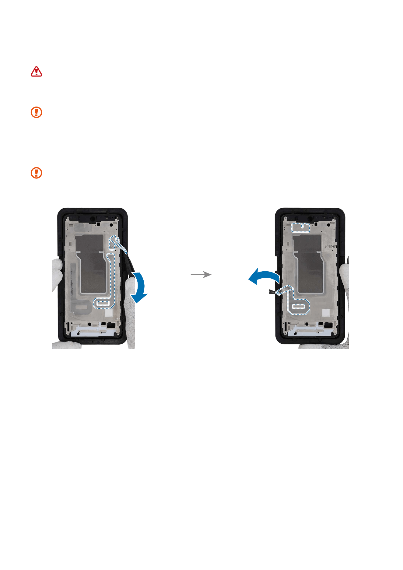
6 While pulling up the suction cup with strong, steady force to create the gap between
the screen and the device frame, place the wide side of the opening pick in the gap
between the top edge of the screen and the device frame and slice through the
adhesive of screen edge. Repeat this on all the sides of the screen and slice through
the adhesive.
Disassembly and Assembly
128
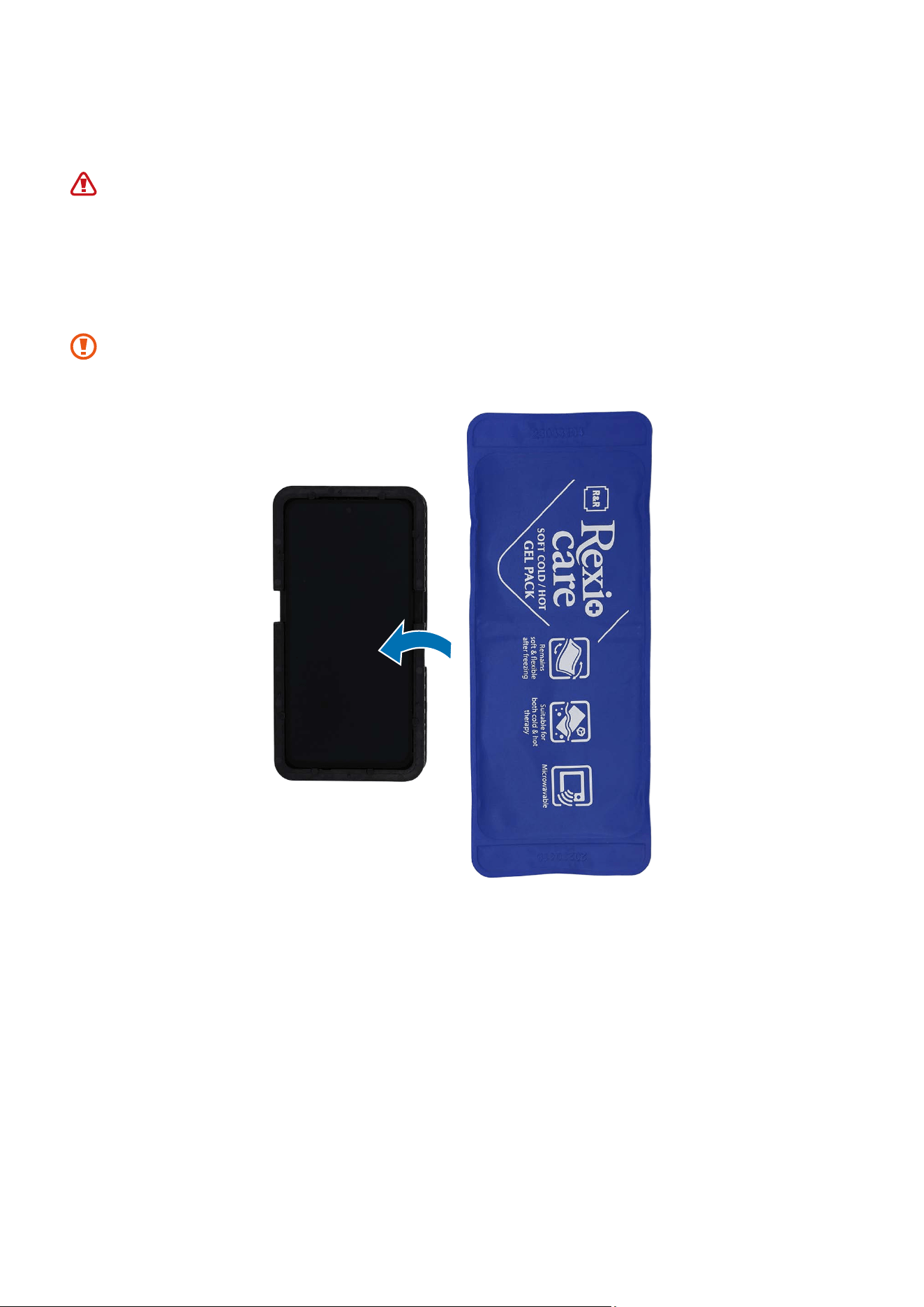
7 Heat the microwaveable heating bag for 30 seconds (Standard: 700 W microwave)
and apply it to the screen for 3 minutes.
•
It is possible for the device or battery to be damaged by heat.
•
Do not heat the device in a microwave. Doing so could cause an explosion.
•
If your device’s glass breaks, the debris can cause injury to your hands or
other body parts. For your safety, attach an acrylic protective cover before
disassembling the device.
Be careful not to damage the device through excessive heat. (It is recommended
to disassemble the device in an area with temperature gauge.)
Disassembly and Assembly
129
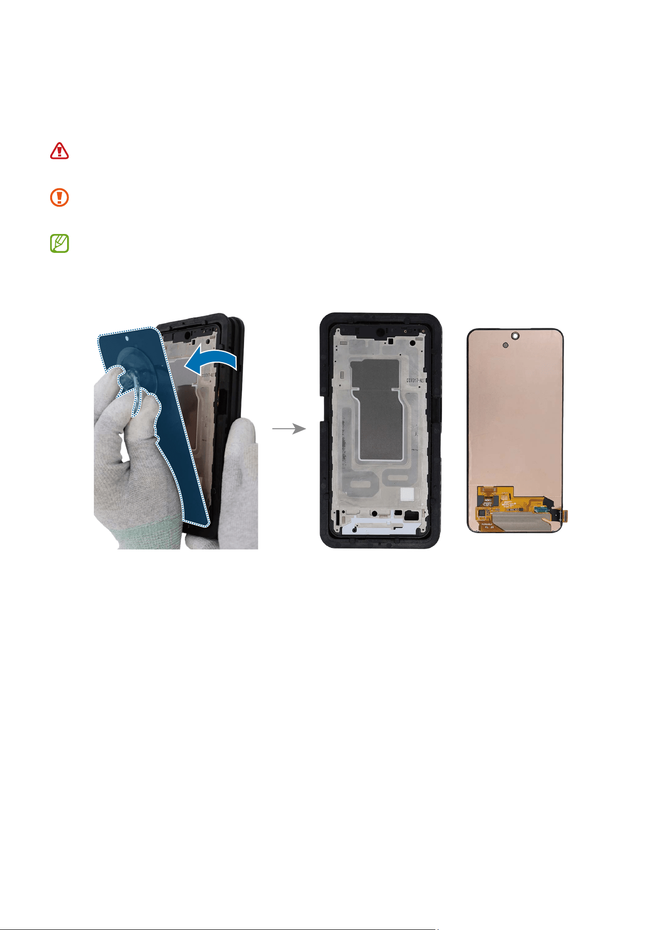
8 Place the suction cup in the centre of the screen and pull up the suction cup with
strong, steady force to separate the screen from the device frame. Lift up the screen
slowly and remove it completely from the device.
For separable handle suction cups, be careful not to injure yourself as the handle
can be parted during use.
Be careful that the suction cup does not adhere to the area where the tape or
sticker is attached.
If you have trouble creating a gap, heat the microwaveable heating bag
additionally, and apply it on the screen to further soften the adhesive. When
reheating, it should be heated no longer than 30 seconds.
Disassembly and Assembly
130
Reassembly
Leaving screws inside the device may damage internal components, such as the
battery. When assembling, be extra careful not to leave any unassembled screws
inside the device.
Before attaching the screen, make absolutely sure that there are no screws,
miscellaneous parts, or other foreign objects on the inside of the device (among
the battery, PBA, etc.).
1 Using the tweezers, remove all adhesive tapes on the metal frame.
Make sure to remove any residual tapes attached to the metal frame before
reassembling the new screen.
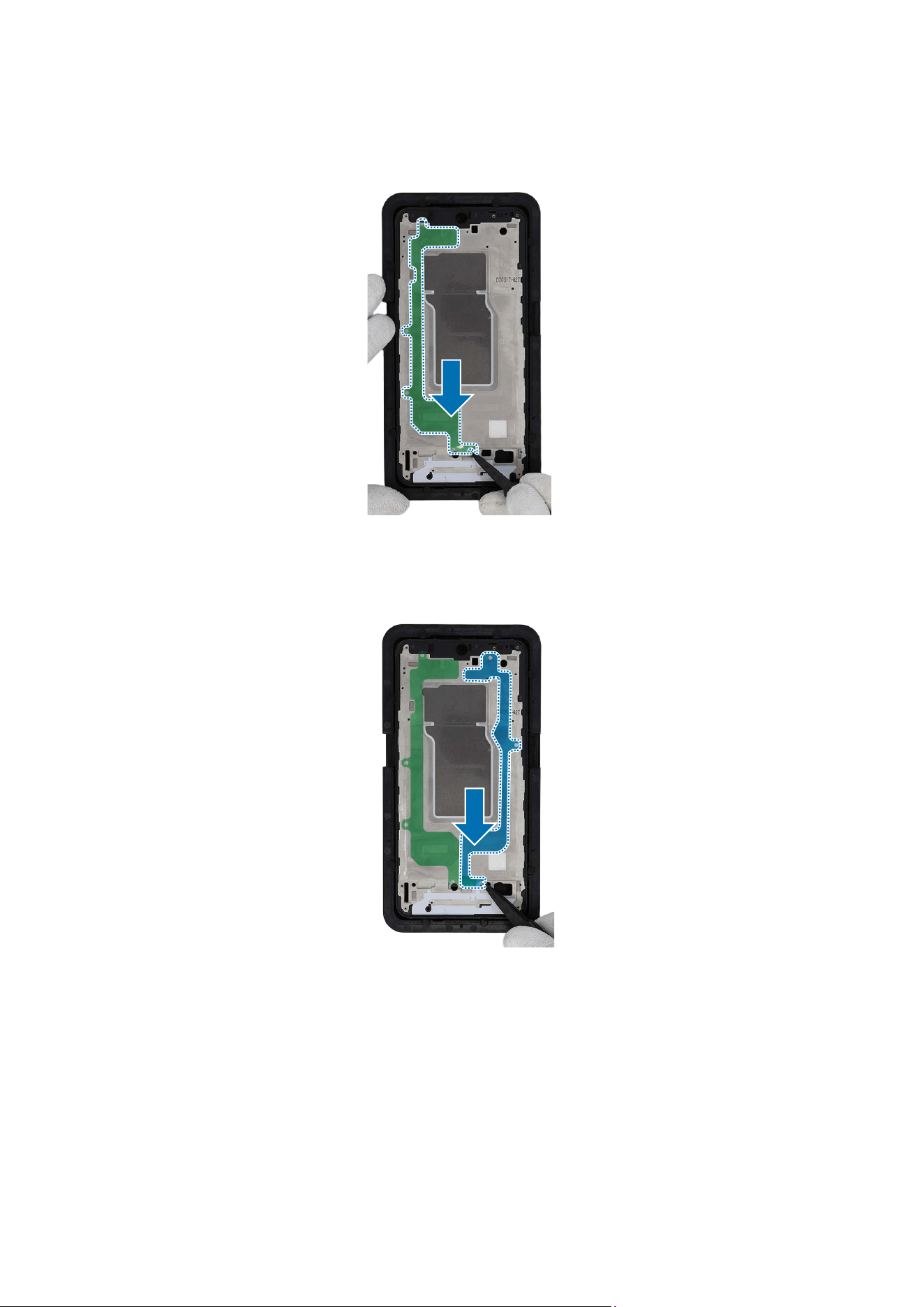
Disassembly and Assembly
131
2 Remove the transparent film of new screen left adhesive tape. Using the tweezers,
align the adhesive tape precisely on the metal frame and attach it.
3 Remove the transparent film of new screen right adhesive tape. Using the tweezers,
align the adhesive tape precisely on the metal frame and attach it.
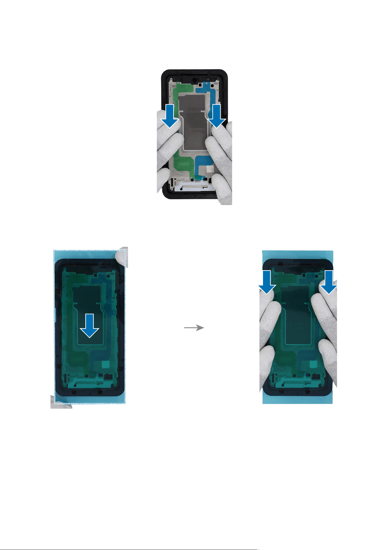
Disassembly and Assembly
132
4 Gently press around the tape to ensure a secure fit.
5 Remove the transparent film of screen side adhesive tape. Using your fingers, align
the adhesive tape precisely on the device frame and attach it.
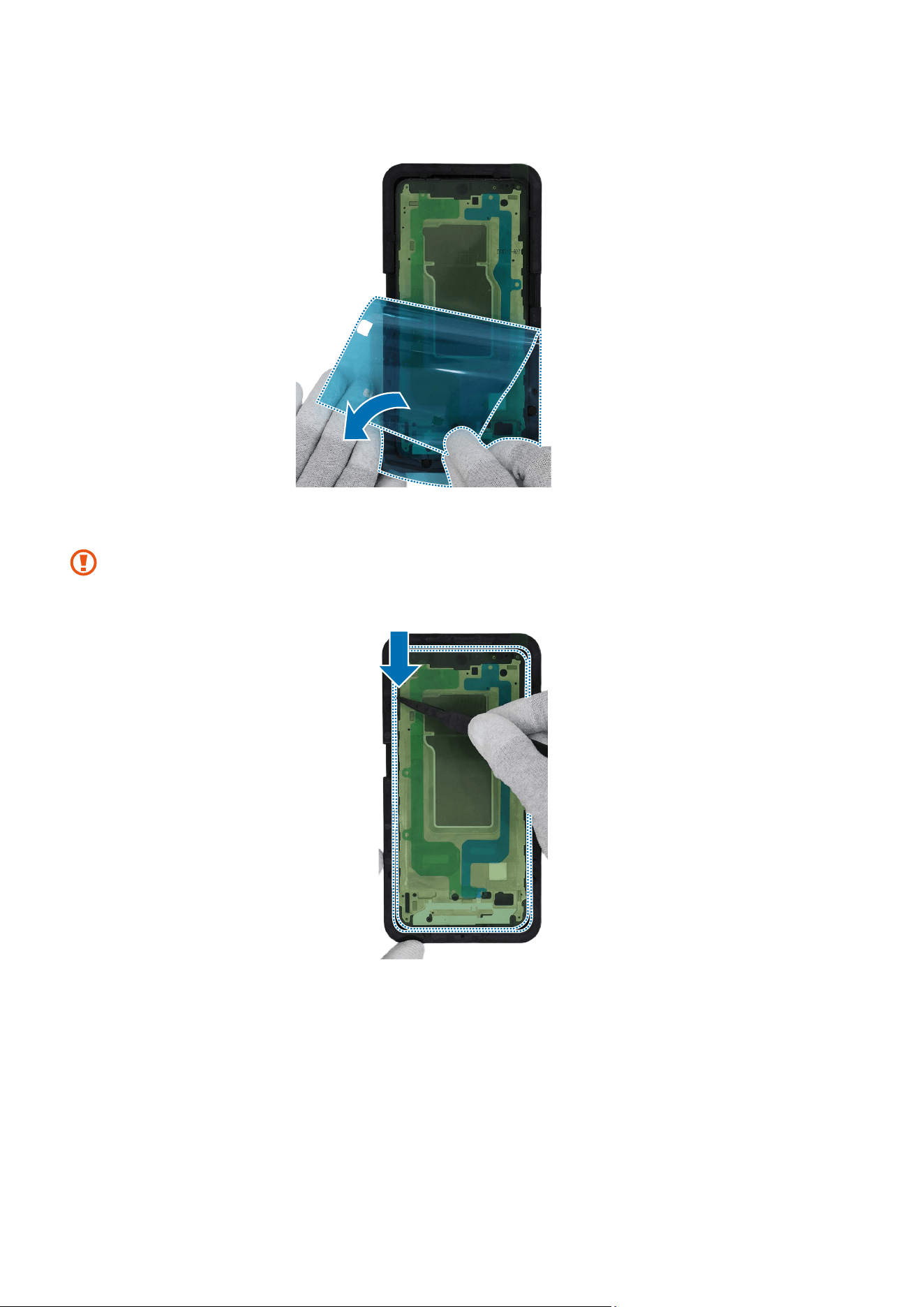
Disassembly and Assembly
133
6 Remove the guide film of the screen side adhesive tape.
7 Using the tweezers, gently press around the edges of tape to ensure a secure fit.
Be careful that the tape may be attached incorrectly if you tilt the device and
place it in the tray.
Disassembly and Assembly
134
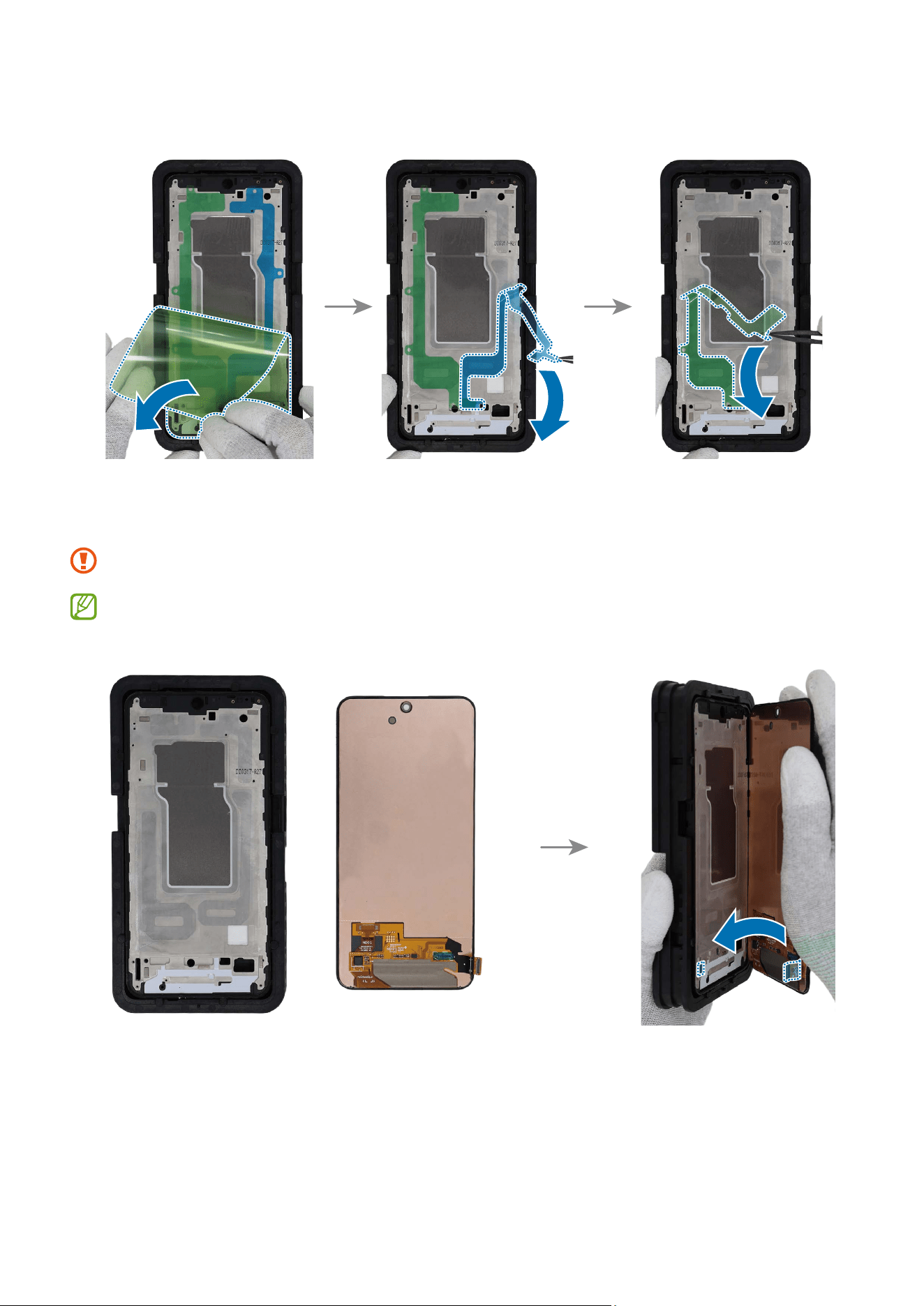
8 Using tweezers, remove all release films of the attached adhesive tapes one by one.
9
Carefully insert the screen connector of the new screen into the screen connector
hole of the device frame and attach the screen slowly.
Be careful not to damage the near components.
If you feel a gap, remove the screen and attach it again. Some foreign materials
can be inside the device.
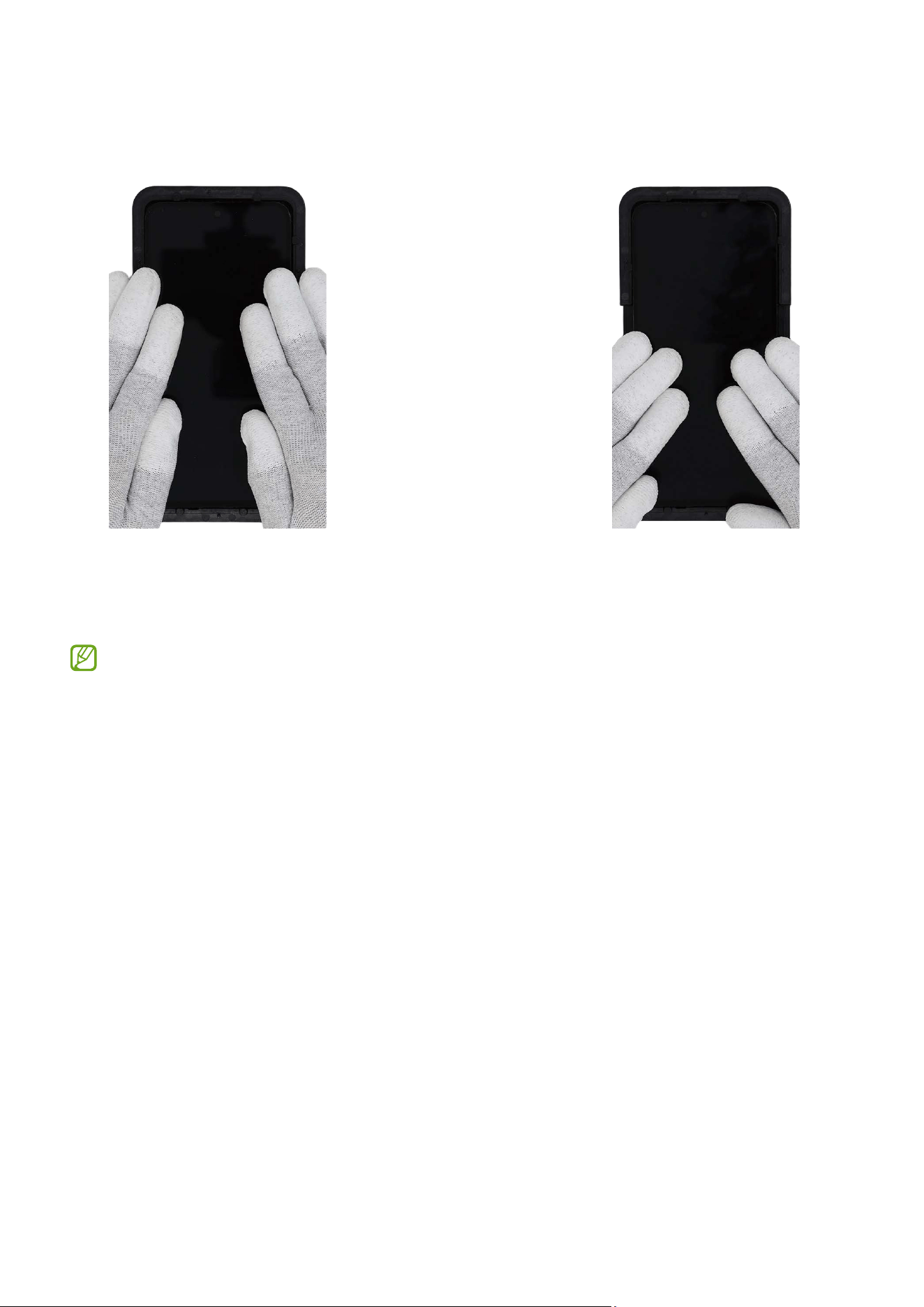
Disassembly and Assembly
135
10
Press down all the edges of the screen evenly in order to attach the screen perfectly.
Ensure that there are no abnormalities.
11
If the press tray is bundled with the repair parts you ordered, check for the steps
of the Screen Press. You can further press the fully assembled screen using the
appropriate tool.
Availability of the bundle tool may vary depending on the country and are
currently available only in limited countries.
Disassembly and Assembly
136
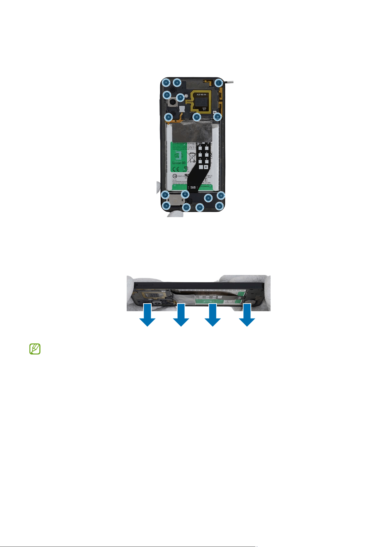
12
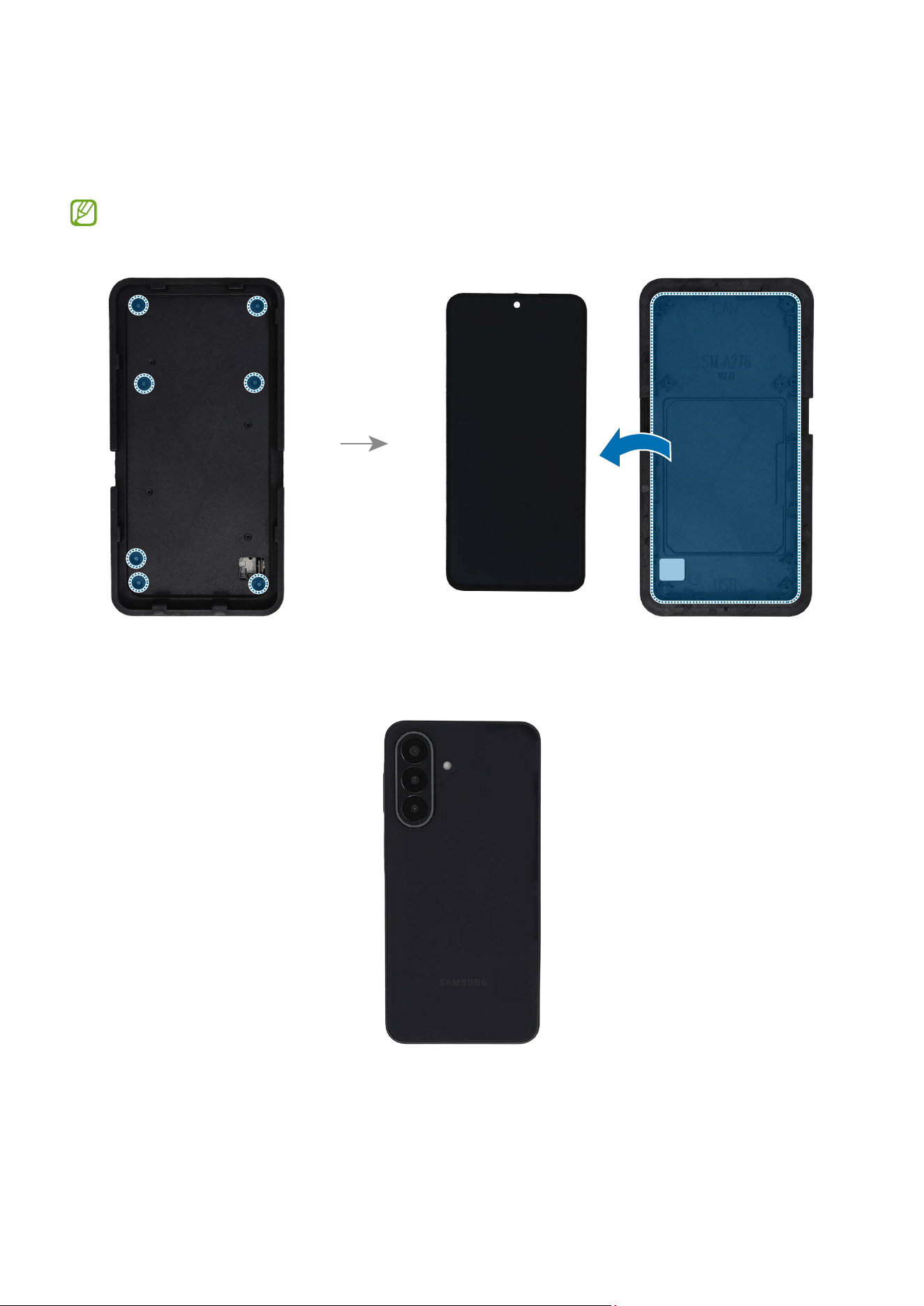
Check the 7 screws at the 7 different points on the rear and remove them using a
cross-head screwdriver. Remove the display module from the display disassembly
tool.
Check the number of screws that have been removed, and store them carefully to
make sure that no unassembled screws are left inside the device during assembly.
13
Check for the reassembly steps of the Screen Module and completely reassemble all
the parts including the back cover.
Disassembly and Assembly
137
Battery
•
The battery should be replaced only by the specialised technicians with the
knowledge and experience to repair electronic devices.
•
The separated battery may be damaged. Do not use it again.
Disassembly
Remove the SIM Card Tray and Back Cover first before you begin.
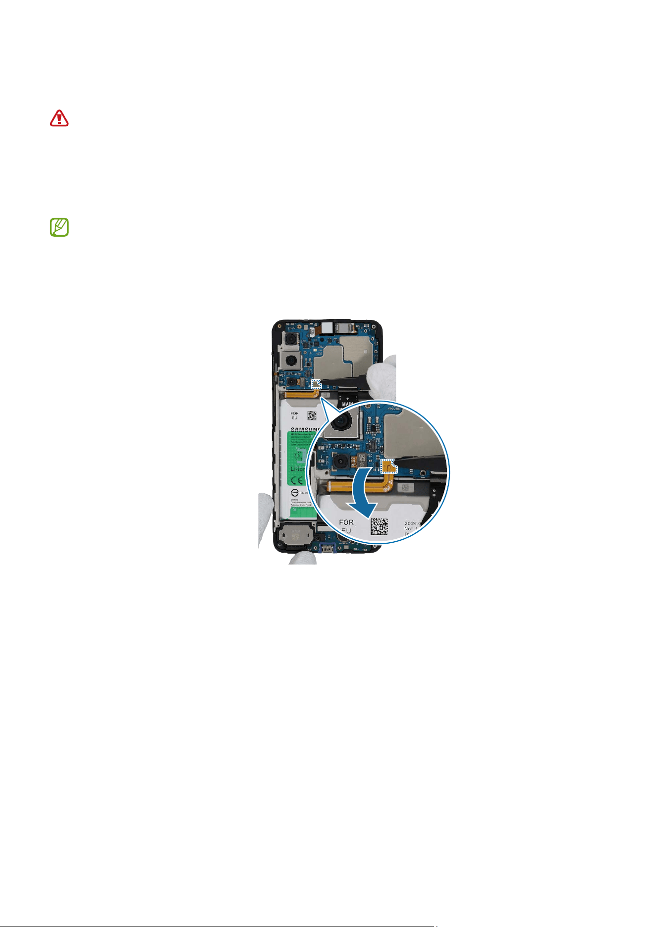
1 Check for the disassembly steps of the Front Camera and completely separate the
battery connector.
Disassembly and Assembly
138
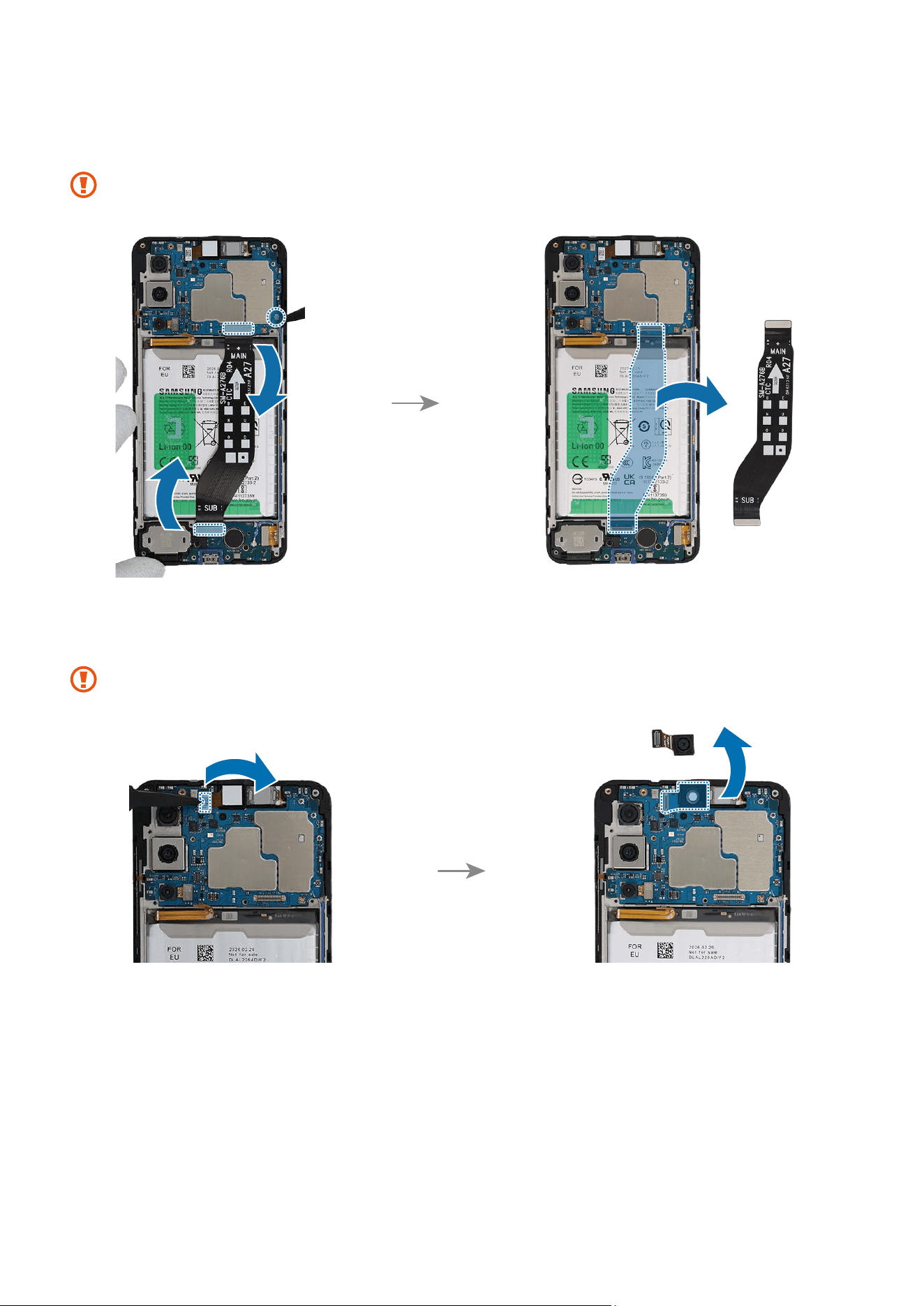
2 Using the tweezers, disconnect the 3 connectors and remove the flex cable
completely.
When removing the connectors, be careful not to damage the cable.
3 Using the tweezers, separate the front camera connector from the main board and
remove the front camera carefully from the device. Leave the camera lens facing up.
Be careful not to touch the camera lens while removing the camera.
Disassembly and Assembly
139
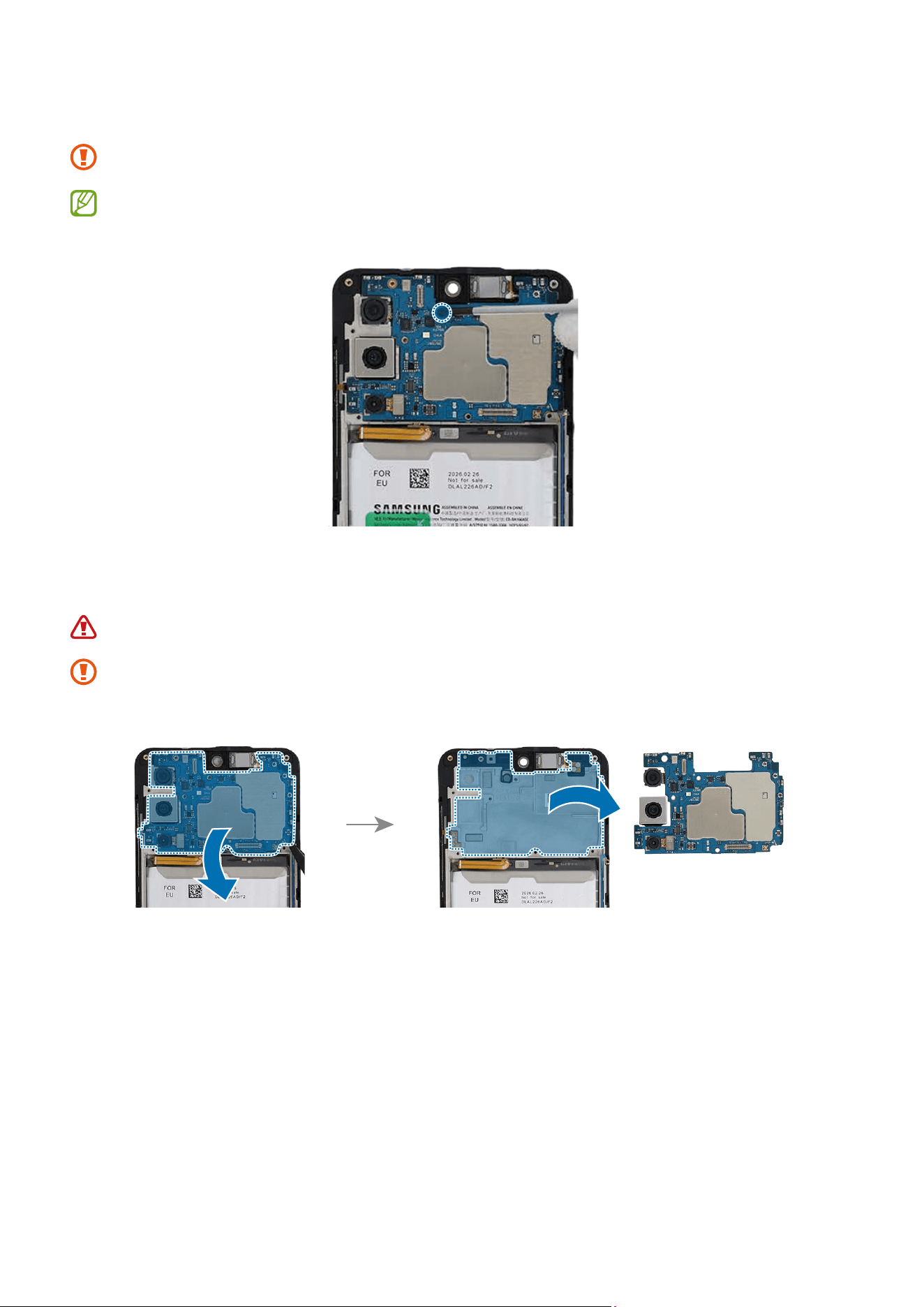
4 Check the 1 screw on the main board and remove it using a cross-head screwdriver.
Be careful not to damage the main board and near components.
Check the number of screws that have been removed, and store them carefully to
make sure that no unassembled screws are left inside the device during assembly.
5 Using the tweezers, lift up on the separator groove of the main board and remove it
carefully.
Be careful not to damage the battery.
The FPCB cables have to be positioned outside so as not to interfere when
disassembling the main board.
Disassembly and Assembly
140
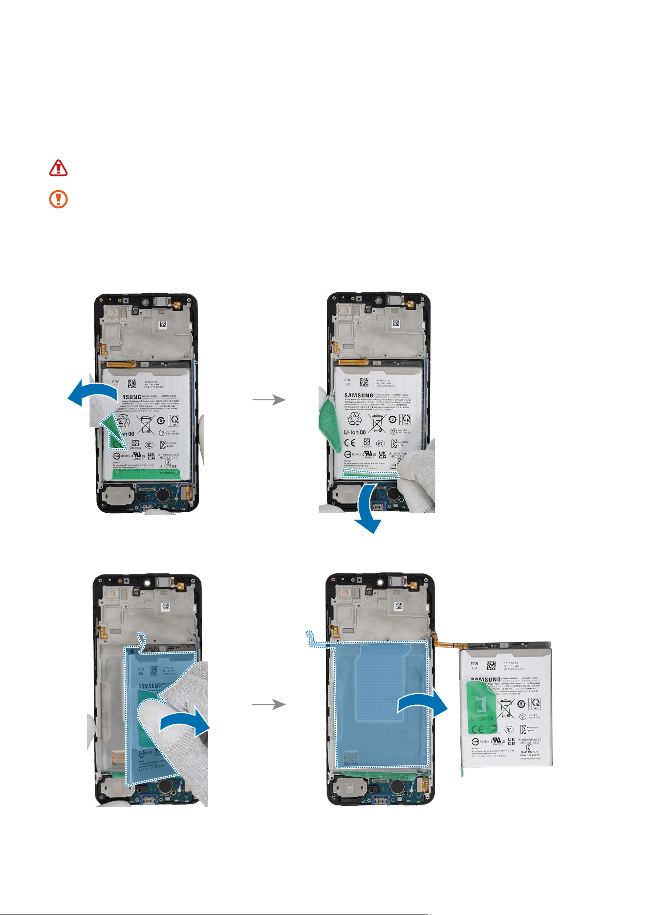
6 Using your fingers, grab the tapes attached to left side and bottom side of the battery
and separate it carefully from the battery. Then, grab the left side tape handle with
fingers and pull it up carefully. Slowly lift up the battery from the device and remove
it completely.
The separated battery may be damaged. Do not use it again.
•
As the adhesive securing the battery is very strong, remove slowly.
•
FPCB cables and connectors have to be positioned outside so as not to interfere
when disassembling the battery.
•
Be careful not to damage the near components and the connectors.
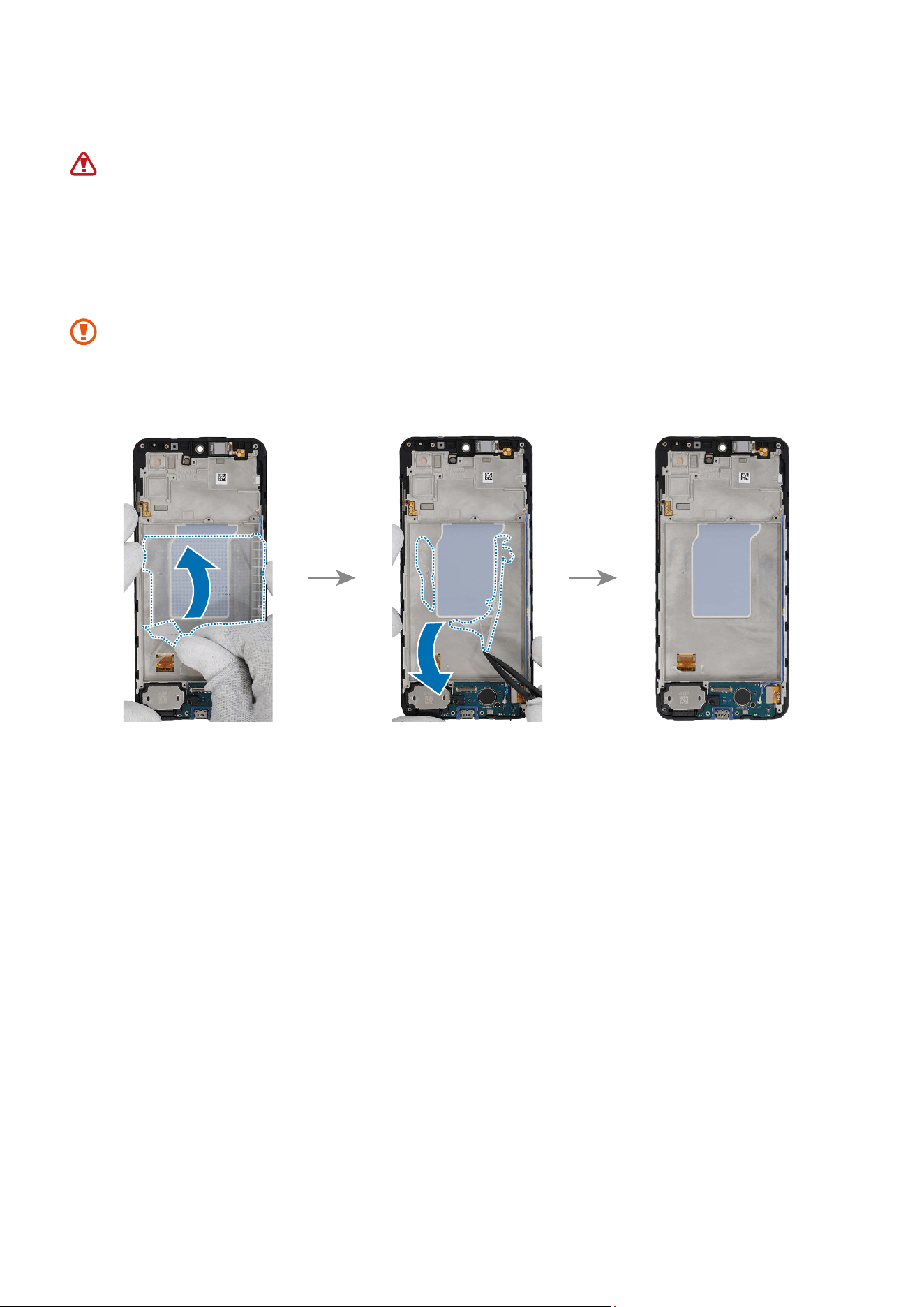
Disassembly and Assembly
141
Reassembly
Leaving screws inside the device may damage internal components, such as the
battery. When assembling, be extra careful not to leave any unassembled screws
inside the device.
1 Using the tweezers and your fingers, remove all the remaining adhesive tapes on the
metal frame.
•
Make sure to remove any residual tapes attached to the metal frame before
reassembling the new battery.
•
Be careful not to damage the device and the near components.
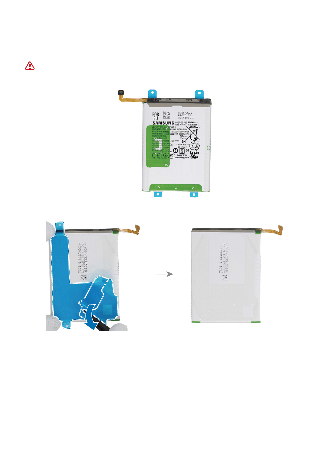
Disassembly and Assembly
142
2 Using the tweezers or your fingers, carefully remove the release film from the new
battery.
Be careful not to damage the battery.
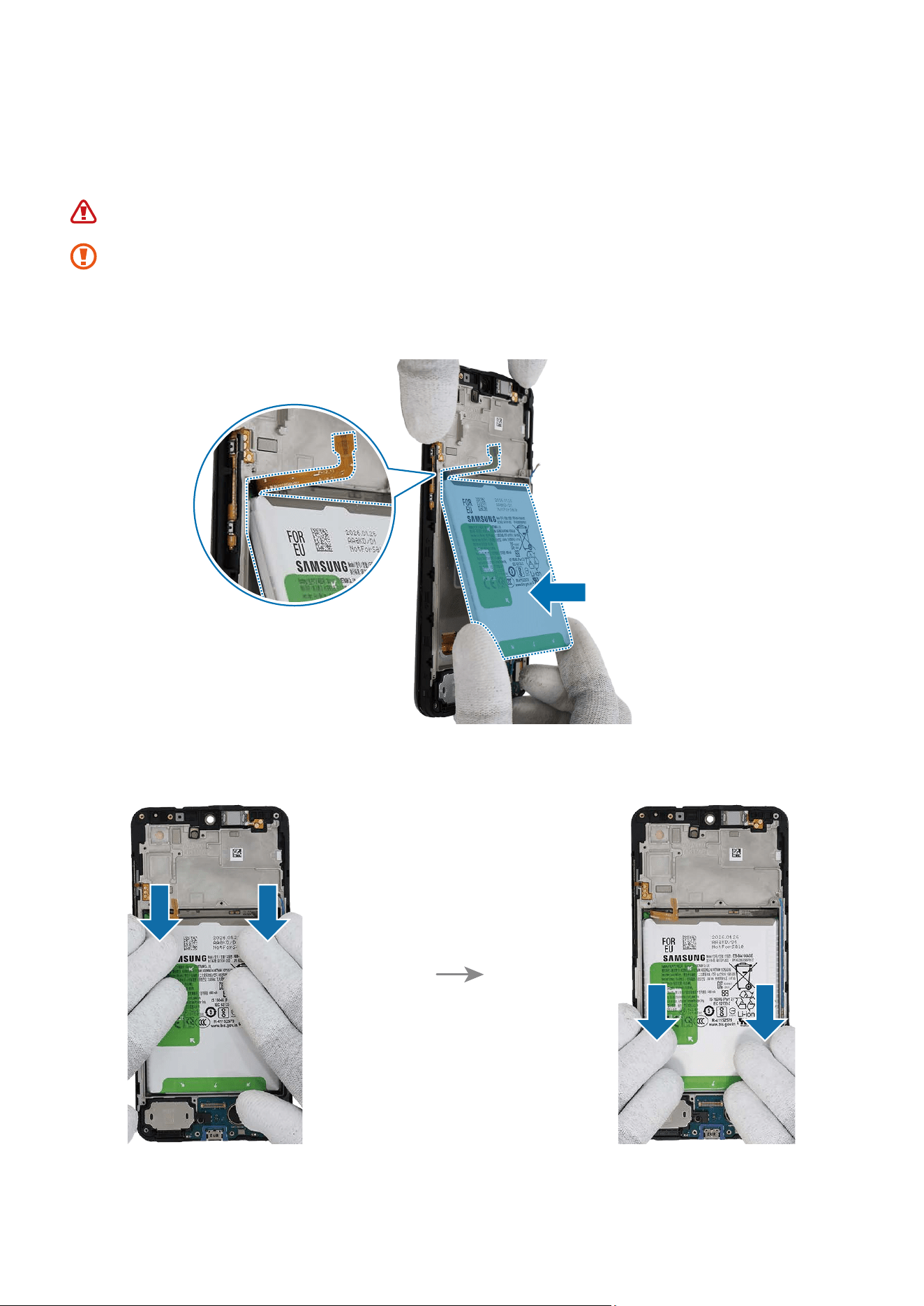
Disassembly and Assembly
143
3 With the battery connector on the left, carefully place the battery based on the upper
left side of the battery. Assemble the battery to the exact position of the metal frame
using your fingers.
Be careful not to damage the battery.
•
FPCB cables and connectors have to be positioned outside so as not to interfere
when assembling the battery.
•
Be careful not to damage the near components.
4 Press the battery with your fingers softly so that the battery can be attached well.
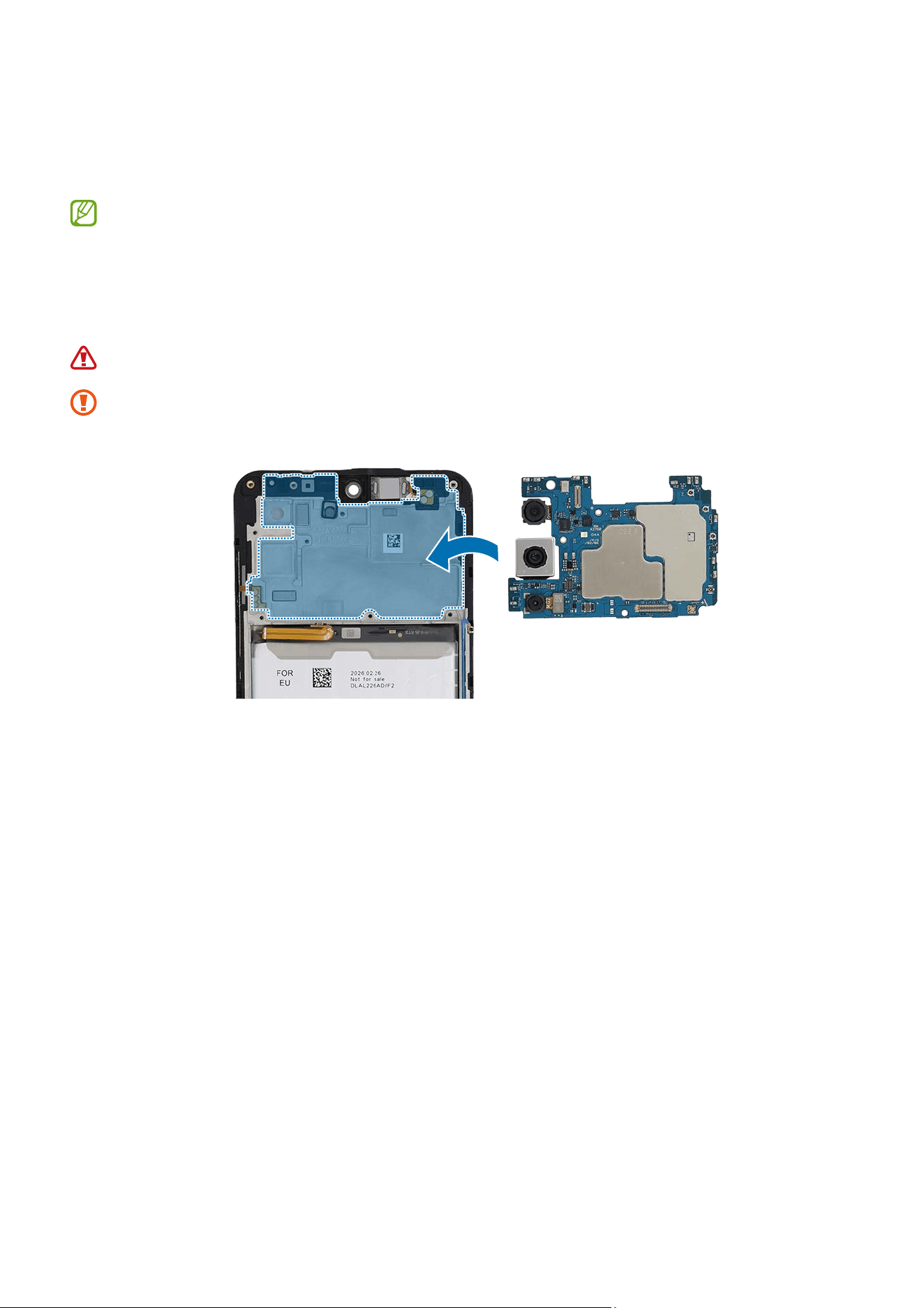
Disassembly and Assembly
144
5 If the press tray is bundled with the repair parts you ordered, check for the steps
of the Battery Press. You can further press the fully assembled battery using the
appropriate tool.
Availability of the bundle tool may vary depending on the country and are
currently available only in limited countries.
6 Align the main board onto the device frame. After attaching the left part of the main
board on the metal frame, assemble the right part.
Be careful not to damage the battery.
The FPCB cables and coaxial cable have to be positioned outside so as not to
interfere when assembling the main board.
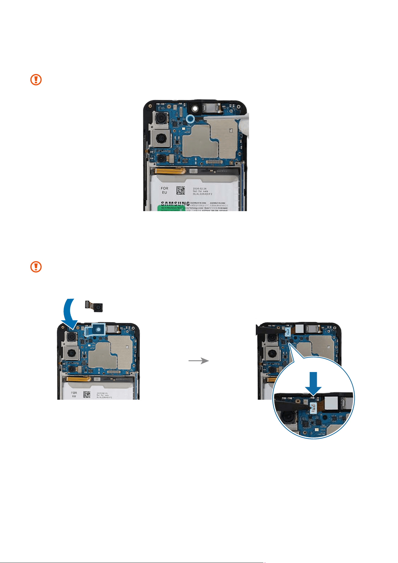
Disassembly and Assembly
145
7 Check the screw 3637 (1 ea) on the main board and fasten it using a cross-head
screwdriver.
Be careful not to damage the near components.
8 Using the tweezers or your fingers, place the front camera in the camera hole so
that the lens faces forward and gently insert. Then, connect the camera connector
carefully on the main board.
•
Be careful not to damage the camera lens and the near components.
•
Be careful not to damage the main board.
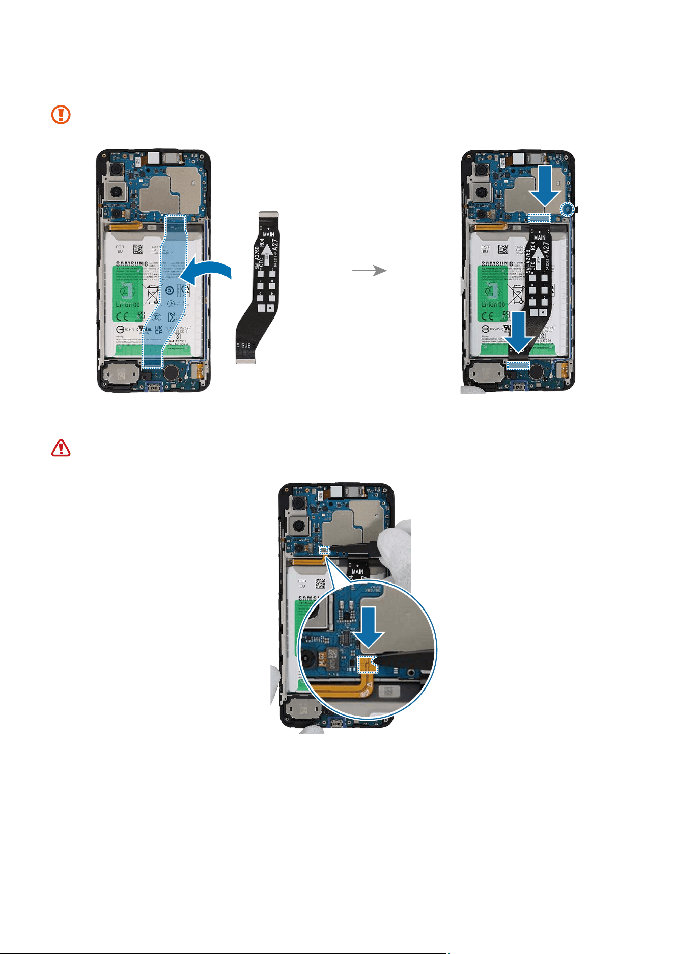
Disassembly and Assembly
146
9 Place the flex cable to the device frame and connect the 3 connectors carefully.
When connecting the connectors, be careful not to damage the cable.
10
Connect the battery connector to the main board.
Be careful not to damage the battery.
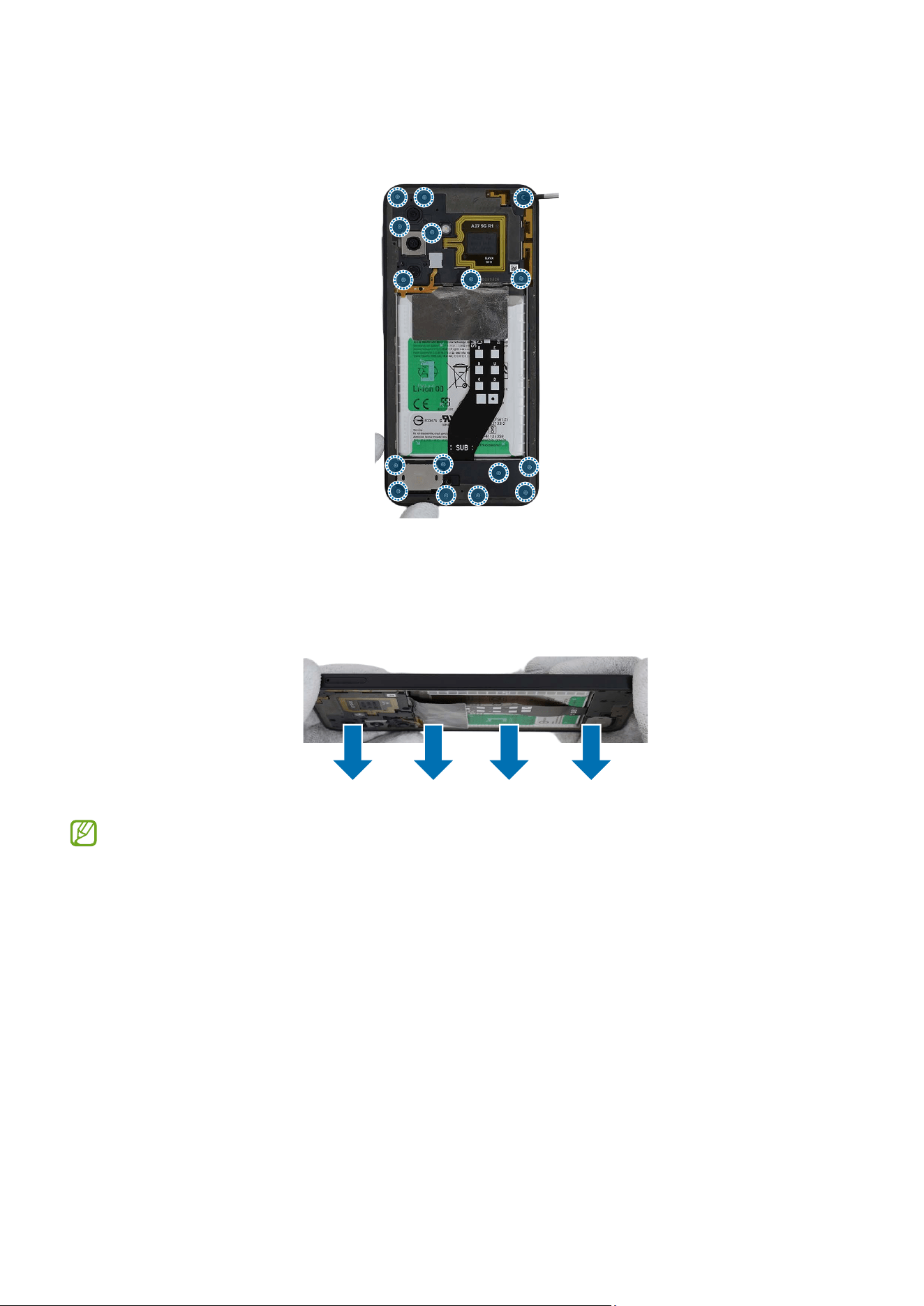
Disassembly and Assembly
147
11
Check for the reassembly steps of the Front Camera and completely reassemble the
bracket.
12
Check carefully with your fingers to see if there are any screws or other foreign
substances inside the device (battery, PBA, cable, etc.). Shake the device lightly with
the back of the device facing down to remove any remaining screws.
Reassemble the Back Cover and SIM Card Tray to complete assembly.

Disassembly and Assembly
148
After reassembling
•
Check whether the parts or sensors in the device work properly with the Self
Repair Assistant app after repairing and assembling your device. Refer to
Calibrations for more information.
•
Visit a Samsung Service Centre when finding some issues from the calibration
results. However, you may incur additional charges if the device has a
malfunction because of DIY repairs.

Disassembly and Assembly
149
Press
•
The Press step is a process for responding to Repair Regulations implemented
in some regions and may not be an essential process in other areas.
•
When repairing the back cover, screen or battery, the press tray can be bundled
with the ordered parts. Availability of bundle tool may vary depending on the
country and is currently available only in limited countries.
Before pressing,
•
Using the press tray, you can further press the fully assembled back cover, screen or
battery.
•
Appropriate tool for pressing the back cover, screen or battery depends on the parts
repaired.
•
Prepare all necessary press tools and make sure to wear the appropriate safety
equipment for your safety.
•
Ensure that the device is fixed on a soft and flat surface.
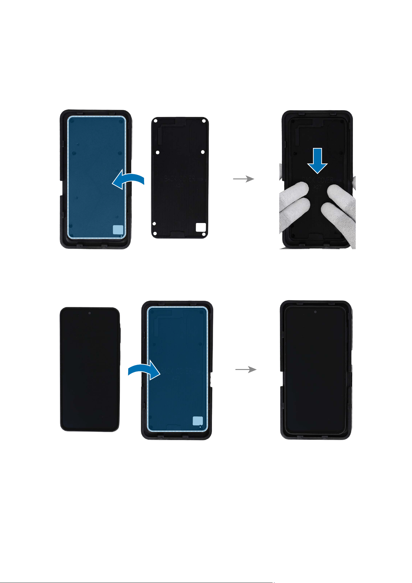
Disassembly and Assembly
150
Back Cover Press
1 Place the bottom rubber pad to the precise position at the back of the bottom press
tray.
2 Place the device on the back cover side of the bottom press tray at the correct
position.
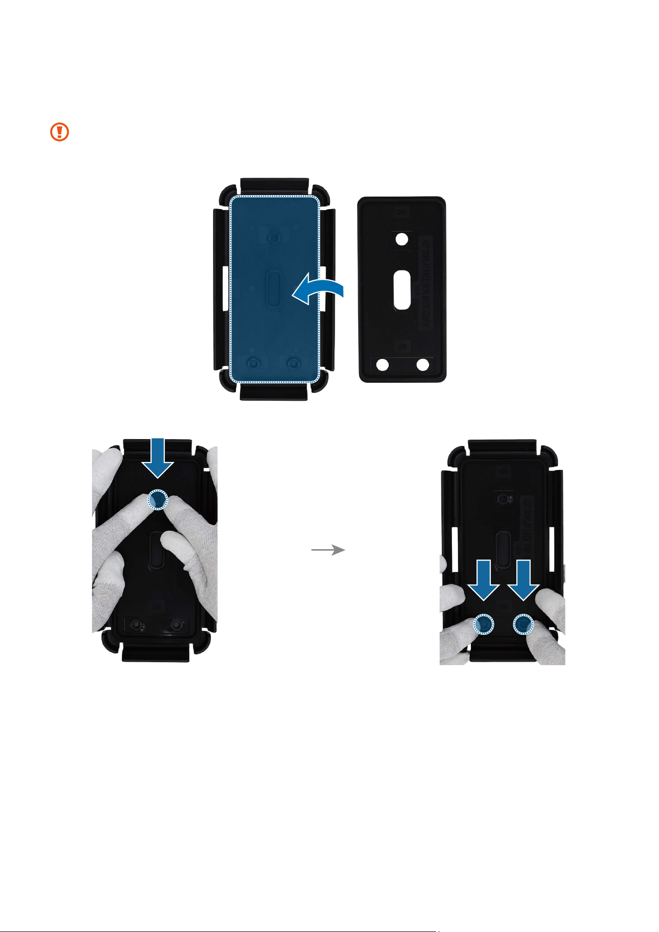
Disassembly and Assembly
151
3 Insert the top rubber pad to the top press tray, and press down on it in its position
smoothly.
Make sure the top rubber pad is properly attached to the hook of the top press
tray.
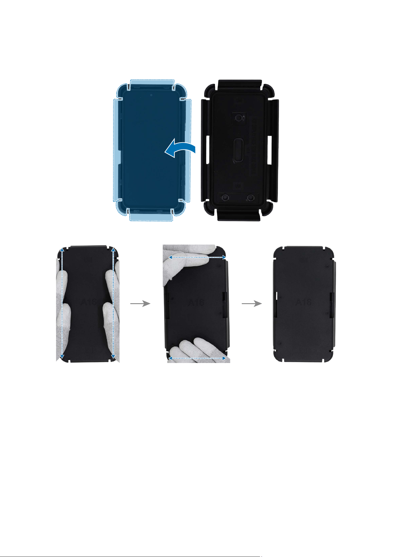
Disassembly and Assembly
152
4 Cover the top press tray so that it fits over the bottom press tray, and press until you
hear a click on all 4 sides. Then, leave it fixed for 5 minutes.
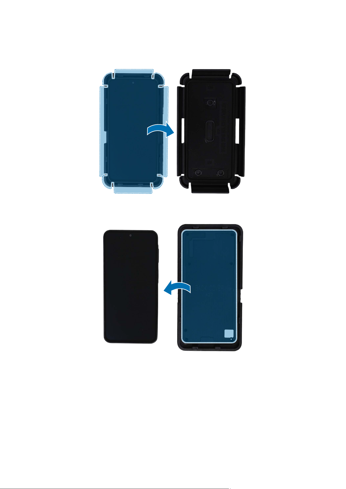
Disassembly and Assembly
153
5 After 5 minutes, slightly lift the clips on top, bottom, left, and right sides to separate
the top press tray.
6 Disconnect the device from the bottom press tray.
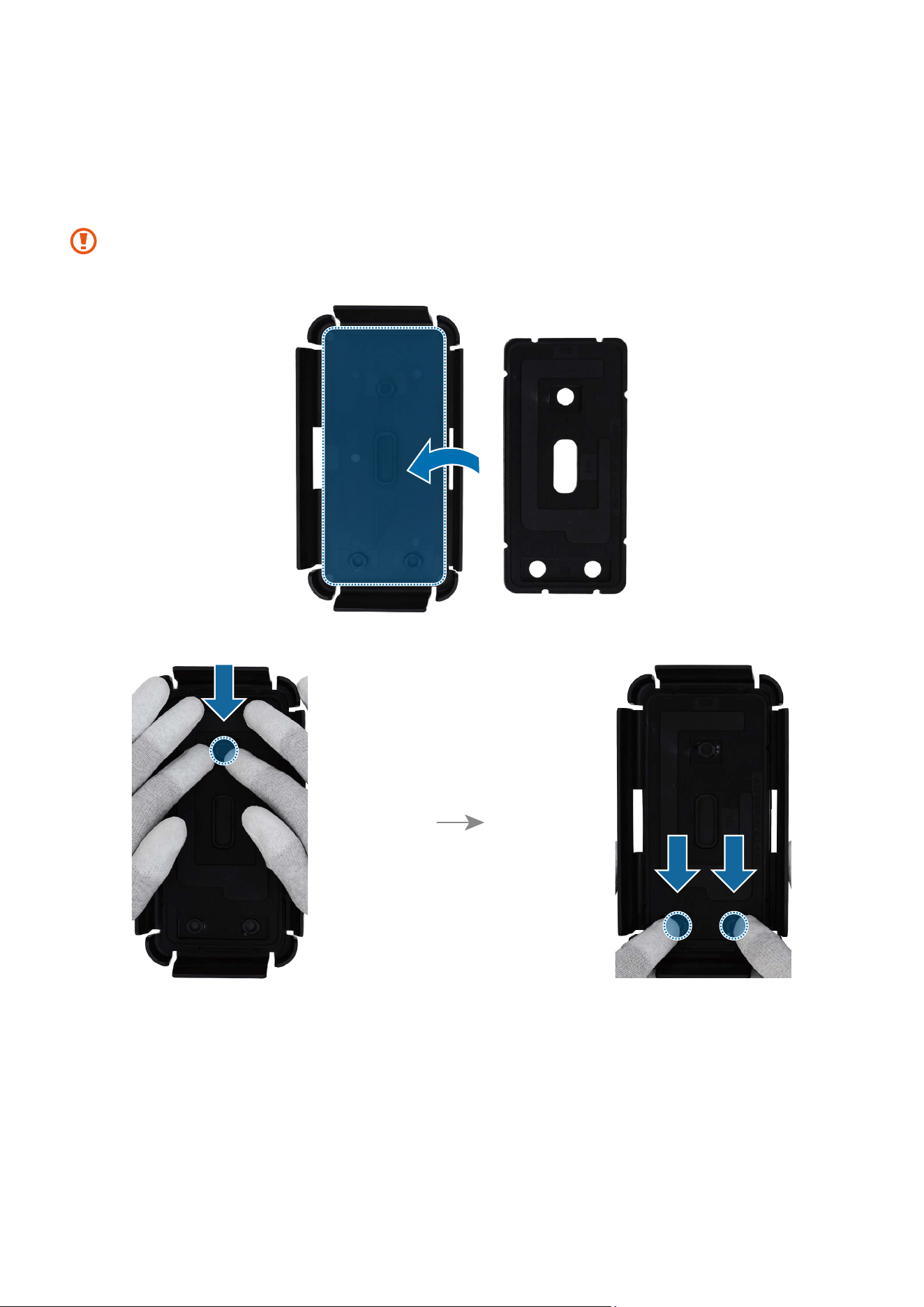
Disassembly and Assembly
154
Screen Press
1 Insert the top rubber pad to the top press tray, and press down on it in its position
smoothly.
Make sure the top rubber pad is properly attached to the hook of the top press
tray.
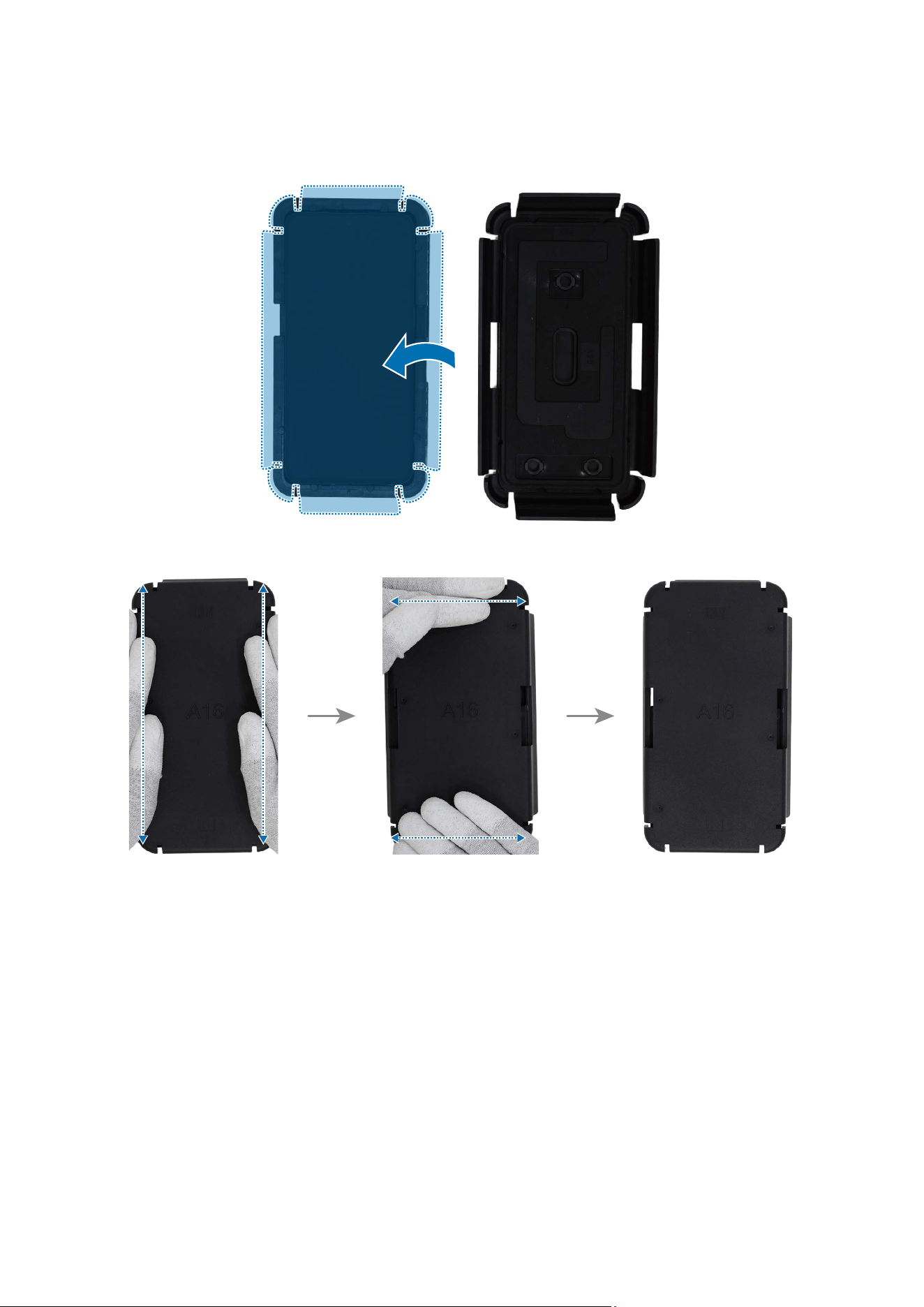
Disassembly and Assembly
155
2 Cover the top press tray so that it fits over the bottom press tray, and press until you
hear a click on all 4 sides. Then, leave it fixed for 5 minutes.
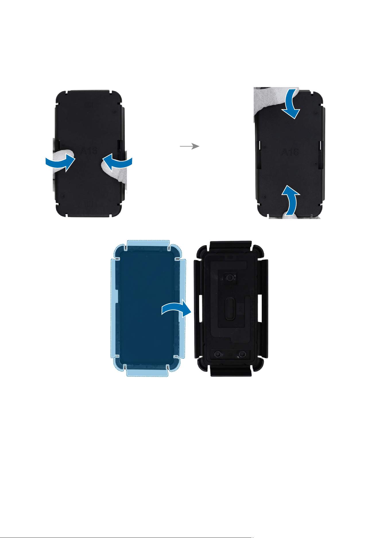
Disassembly and Assembly
156
3 After 5 minutes, slightly lift the clips on top, bottom, left, and right sides to separate
the top press tray.
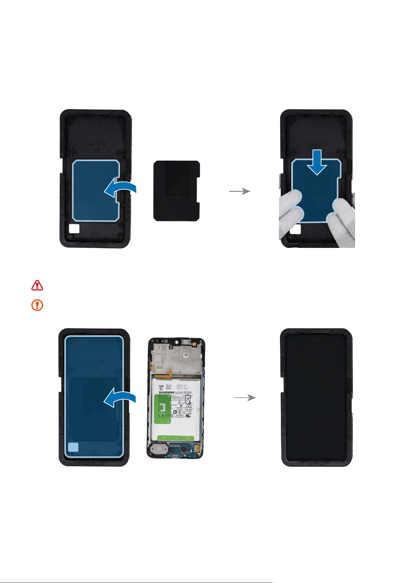
Disassembly and Assembly
157
Battery Press
1 Insert the battery press pad to the front of the bottom press tray, and press down on
it in its position smoothly.
2 Place the screen module on the press bottom at the correct position.
Be careful not to damage the battery.
Be careful not to damage the near components.
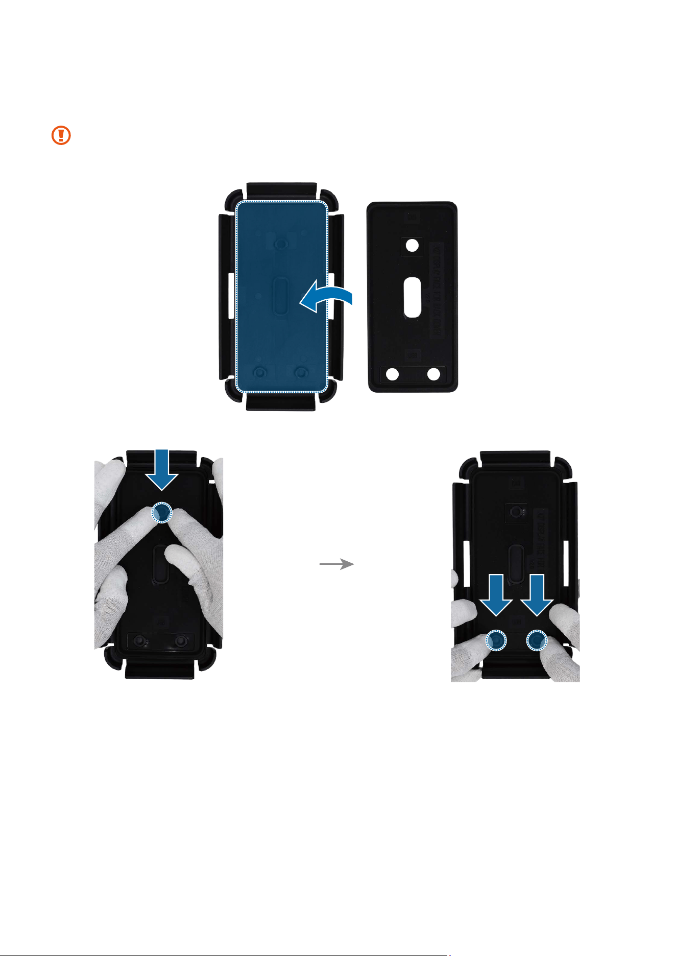
Disassembly and Assembly
158
3 Insert the top rubber pad to the top press tray, and press down on it in its position
smoothly.
Make sure the top rubber pad is properly attached to the hook of the top press
tray.
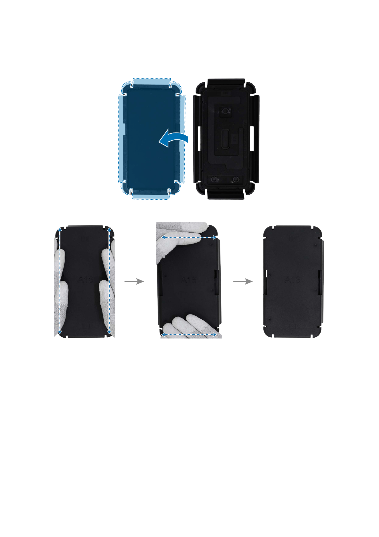
Disassembly and Assembly
159
4 Cover the top press tray so that it fits over the bottom press tray, and press until you
hear a click on all 4 sides. Then, leave it fixed for 5 minutes.
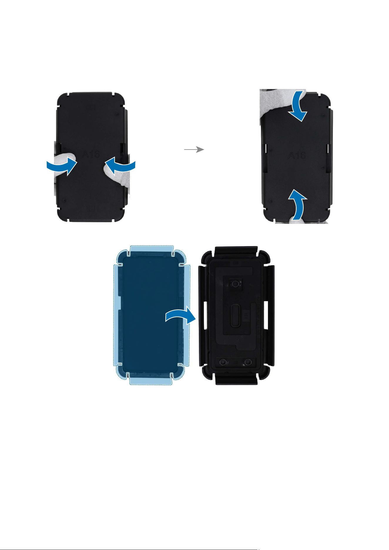
Disassembly and Assembly
160
5 After 5 minutes, slightly lift the clips on top, bottom, left, and right sides to separate
the top press tray.
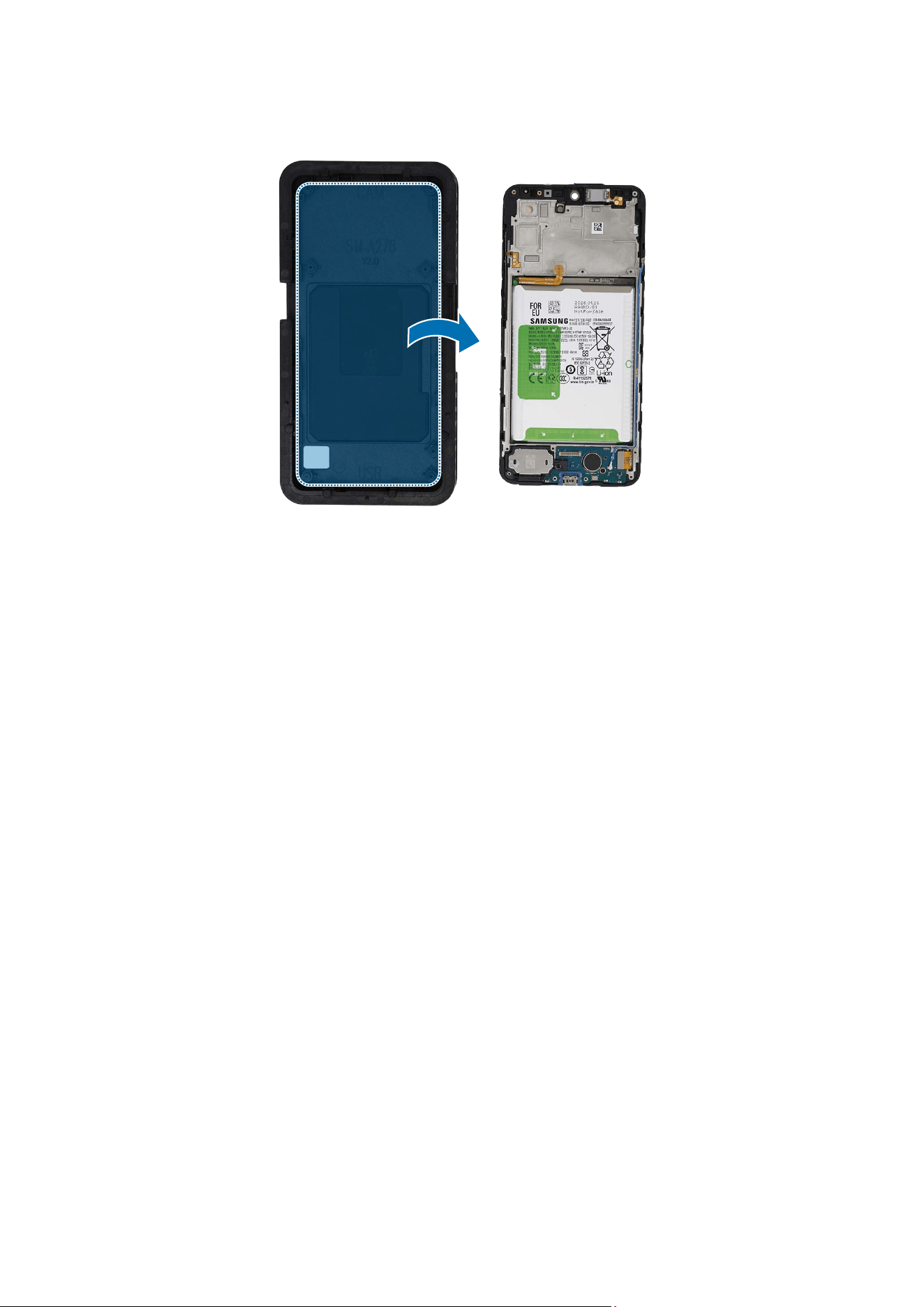
Disassembly and Assembly
161
6 Disconnect the screen module from the Bottom Press Tray.

Disassembly and Assembly
162
Directive 2012/19/EU Annex VII Components
Directive 2012/19/EU Annex VII requirements apply to the following components.
Component Samsung Part Name Removal Instructions
Printed circuit board
if the surface is
greater than 10 square
centimetres
Main Board (PBA)
Check for the disassembly steps of
the Rear Camera and separate the
main board.
Liquid crystal display
of a surface greater
than 100 square
centimetres and all
those back-lighted
with gas discharge
lamps
Screen
Check for the disassembly steps
of the Screen and separate the
screen.
Battery Battery
Check for the disassembly steps
of the Battery and separate the
battery.
External Electric Cable USB Cable
Disconnect the USB cable.

This guide is a property of Samsung Electronics Co., Ltd.
Any unauthorised use of guide can be punished under applicable international and/or
domestic law.
© Samsung Electronics Co., Ltd.
SUB
PMIC
MAIN
PMIC
POWER
RF
SIM/BT/NFC
AUDIO
DISPLAY
DIRECT
CHARGER
[A27] Block Diagram
AP
ACC & GYRO
REAR
WIDE CAM
Memory
(DRAM+Storage)
SIM1/SIM2
MAGNETIC
MAIN DISPLAY
GRIP
FPS
SPK
RCV AMP
FRONT CAM
REAR
UW CAM
AMBIENT
REAR
MACRO CAM
TRANSIEVER
IF PMIC
OVP
SPK AMP
RCV
PAM
FLASH LED
CAMERA
SENSOR
MOTOR LDO
MOTOR
MOTOR
NFC
BT/WIFI