User Guide
Quality, Design and Innovation
home.liebherr.com/fridge-manuals
Contents
1 General safety instructions.................................. 3
2 Appliance at a glance............................................ 3
2.1 Scope of delivery.......................................................... 3
2.2 Overview of appliance and equipment..................... 4
2.3 SmartDevice.................................................................. 4
2.4 Appliance range of use............................................... 4
2.5 Conformity..................................................................... 5
2.6 SVHC substances according to REACH regulation. 5
2.7 EPREL database........................................................... 5
2.8 Spare parts.................................................................... 5
3 Setting up and connecting.................................... 5
3.1 Installation requirements........................................... 5
3.2 Appliance dimensions................................................. 5
3.3 Transporting the appliance........................................ 6
3.4 Unpacking the appliance............................................ 6
3.5 Reversing the door opening direction...................... 6
3.6 Aligning the door.......................................................... 14
3.7 Removing transport lock............................................. 14
3.8 Installing door handle................................................. 14
3.9 Mounting anti-tipping device..................................... 14
3.10 Installing appliance..................................................... 15
3.11 Setting up the appliance so it is level...................... 15
3.12 Installing multiple appliances.................................... 15
3.13 After installation.......................................................... 16
3.14 Disposing of packaging............................................... 16
3.15 Connecting the appliance to the power supply...... 16
4 Functionality of the Touch&Swipe display......... 16
4.1 Navigation and symbol explanation......................... 16
4.2 Menus............................................................................. 17
4.3 Sleep mode................................................................... 18
5 Putting into operation........................................... 18
5.1 Switching on appliance (first use)............................ 18
6 Storage.................................................................. 18
6.1 Information regarding storage................................... 18
6.2 Storage diagram........................................................... 18
7 Saving energy........................................................ 21
8 Controls................................................................. 21
8.1 Control and display elements.................................... 21
8.1.1 Status display............................................................21
8.1.2 Display symbols........................................................ 21
8.1.3 Acoustic signals........................................................22
8.2 Appliance functions..................................................... 22
8.2.1 Notes on the appliance functions......................... 22
8.2.2 Switching appliance on and off ............................ 22
8.2.3 Temperature ............................................................. 22
8.2.4 Presentation light .................................................... 23
8.2.5 HumiditySelect.........................................................23
8.2.6 SabbathMode........................................................... 23
8.2.7 Door lock ................................................................... 24
8.2.8 Display lock .............................................................. 25
8.2.9 Access codes.............................................................25
8.2.10 Reminder ................................................................... 27
8.2.11 Language ...................................................................27
8.2.12 Temperature unit......................................................27
8.2.13 Display brightness ..................................................27
8.2.14 Alarm Sound..............................................................28
8.2.15 Key Sound..................................................................28
8.2.16 WiFi............................................................................ 28
8.2.17 Device information ................................................. 29
8.2.18 Software ...................................................................29
8.2.19 Door alarm ............................................................... 29
8.2.20 Resetting to factory settings ............................... 30
8.3 Message........................................................................ 30
8.3.1 Warnings....................................................................30
8.3.2 Reminders...................................................................31
9 Features................................................................. 32
9.1 Safety lock.................................................................... 32
9.2 Labels............................................................................. 32
9.3 Labels............................................................................. 32
10 Maintenance.......................................................... 32
10.1 FreshAir activated carbon filter................................. 32
10.2 Cleaning the appliance............................................... 33
11 Customer help....................................................... 34
11.1 Technical specifications............................................. 34
11.2 Operating noises.......................................................... 34
11.3 Technical fault.............................................................. 34
11.4 Customer Service......................................................... 36
11.5 Model plate................................................................... 36
12 Shutting down....................................................... 36
13 Disposal................................................................. 36
13.1 Preparing appliance for disposal.............................. 36
13.2 Disposing of the appliance in an environmentally
friendly manner............................................................ 37
The manufacturer is continually working on the further
development of all types and models. Please be aware that
we reserve the right to make changes to the shape, equip‐
ment and technology.
Symbol
Explanation
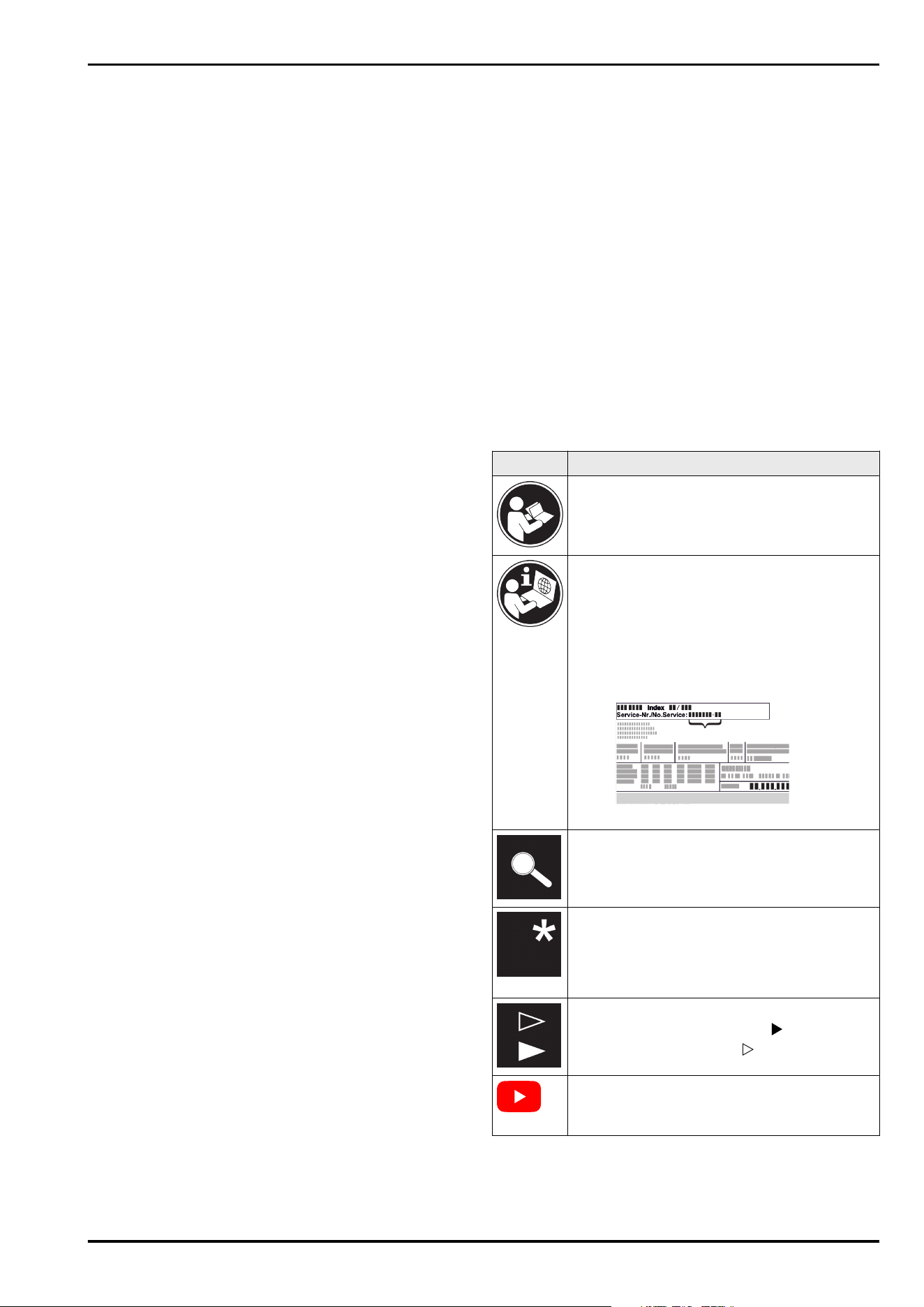
Read instructions
Please read the information in these instruc‐
tions carefully to understand all of the benefits
of your new appliance.
Additional information on the Internet
The digital manual with additional informa‐
tion and in other languages can be found
via the QR code on the front of the
manual or by entering the service number at
home.liebherr.com/fridge-manuals.
The service number can be found on the serial
tag:
Fig.Example illustration
Check appliance
Check all parts for transport damage. If you
have any complaints, please contact your
agent or customer service.
Differences
These instructions apply to a range of models,
so differences are possible. Sections that
apply to certain models only are marked with
an asterisk (*).
Instructions and results
Instructions are marked with a .
Results are marked with a .
Videos
Videos about the appliances are available on
the YouTube channels of Liebherr-Hausgeräte.
Open source licences:
The appliance contains software components that use
open source licences. Information on the open source
licences used can be found here: home.liebherr.com/
open-source-licences
2 * Depending on model and options
These operating instructions apply to:
WFbli 5041 WFbli 5241 WFbli 7741
1 General safety instructions
Please keep these operating instructions in a safe place so
you can refer back to them at any time.
If you pass the appliance on, please hand these operating
instructions to the next user.
Read these operating instructions carefully before use to
ensure safe and correct use of the appliance. Follow the
instructions, safety instructions and warning messages
included at all times. They are important for ensuring you
can operate and install the appliance safely and without any
problems.
Danger for the user:
-
This device can be used by children and people with
impaired physical, sensory or mental abilities or with a
lack of experience and knowledge provided that they are
supervised or have received instruction in the safe use of
this device, and about the resulting hazards.
Children must not play with this appliance. Cleaning and
user maintenance work must not be carried out by chil‐
dren without adult supervision. Children aged between
3 and 8 are allowed to load and unload the appliance.
Children below the age of 3 must be kept away from the
appliance unless they are under continuous adult super‐
vision.
-
The socket must be easily accessible so that the appli‐
ance can be disconnected quickly from the electricity in
an emergency. It must not be located in the area behind
the appliance.
-
When disconnecting the appliance from the supply,
always take hold of the plug. Do not pull the cable.
-
In the event of a fault pull out the mains plug or deacti‐
vate the fuse.
-
Do not damage the mains power cable. Do not operate
the appliance with a defective mains power cable.
-
Only customer service or other specially trained staff
may repair or perform other operations on the appliance.
-
Only assemble, connect and dispose of the appliance
according to the instructions.
Fire hazard:
-
The coolant used (information on the model plate) is
ecofriendly but also flammable. Any leaking coolant may
ignite.
•
Do not damage the refrigerant circuit pipes.
•
Do not handle ignition sources inside the appliance.
•
Do not use electrical appliances inside the appliance
(e.g. steam cleaners, heaters, ice cream makers, etc.).
•
If the refrigerant leaks: remove any naked flames or
ignition sources from the vicinity of the leakage point.
Properly air the room. Inform customer services.
-
Do not store explosives or sprays using combustible
propellants such as butane, propane, pentane, etc. in the
appliance. To identify these spray cans, look for the list of
contents printed on the can, or a flame symbol. Gases
possibly escaping may ignite due to electrical compo‐
nents.
-
Keep burning candles, lamps and other items with naked
flames away from the appliance so that they do not set
the appliance on fire.
-
Please be sure to store alcoholic drinks or other pack‐
aging containing alcohol in tightly closed containers.
Any alcohol that leaks out may be ignited by electrical
components.
Danger of tipping and falling:
-
Do not misuse the plinth, drawers, doors etc. as a step or
for support. This applies particularly to children.
Danger of food poisoning:
-
Do not consume food which has been stored too long.
Danger of frostbite, numbness and pain:
-
Avoid prolonged skin contact with cold surfaces or refri‐
gerated/frozen goods or take protective measures, e.g
wear gloves.
Danger of injury and damage:
-
Hot steam can lead to injury. Do not use electrical
heating or steam cleaning equipment, open flames or
defrosting sprays to defrost.
-
Do not use sharp implements to remove the ice.
Risk of crushing:
-
Do not hold the hinge when opening and closing the door.
Fingers may get caught.
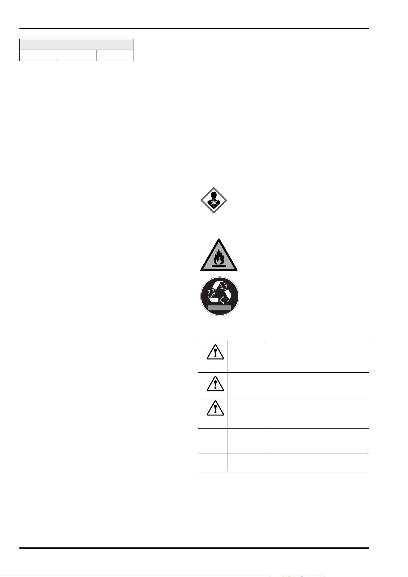
Symbols on the appliance:
This symbol may be located on the
compressor. It relates to the oil in the
compressor and makes reference to the
risk that: Swallowing or inhaling can be
fatal. This advice is only relevant to recy‐
cling. There is no danger in normal opera‐
tion.
This symbol is located on the compressor
and indicates the danger of flammable
materials. Do not remove the sticker.
This or a similar sticker may be located
on the rear of the appliance. This sticker
indicates that there are vacuum insulation
panels (VIP) or perlite panels in the door
and/or housing. This advice is only relevant
to recycling. Do not remove the sticker.
Please note the warning messages and other specific
advice in the other chapters:
DANGER
indicates an immediately
hazardous situation which will
lead to death or serious injuries if
it is not avoided.
WARNING indicates a hazardous situation
which may lead to death or serious
injuries if it is not avoided.
CAUTION indicates a hazardous situation
which may lead to minor or
moderate injuries if it is not
avoided.
NOTICE indicates a hazardous situation
which may lead to damage to
property if it is not avoided.
Note indicates useful instructions and
tips.
2 Appliance at a glance
2.1 Scope of delivery
Check all parts for transport damage. Contact your
dealer or customer service in the event of complaints.
(see11.4 Customer Service)
General safety instructions
* Depending on model and options 3
Your new appliance comes with the following parts:
-
Standalone appliance
-
Features (depending on the model)
-
Installation materials (depending on the model)
-
“Quick Start Guide”
-
“Installation Guide”
-
“Installation Guide”*
-
Service Brochure
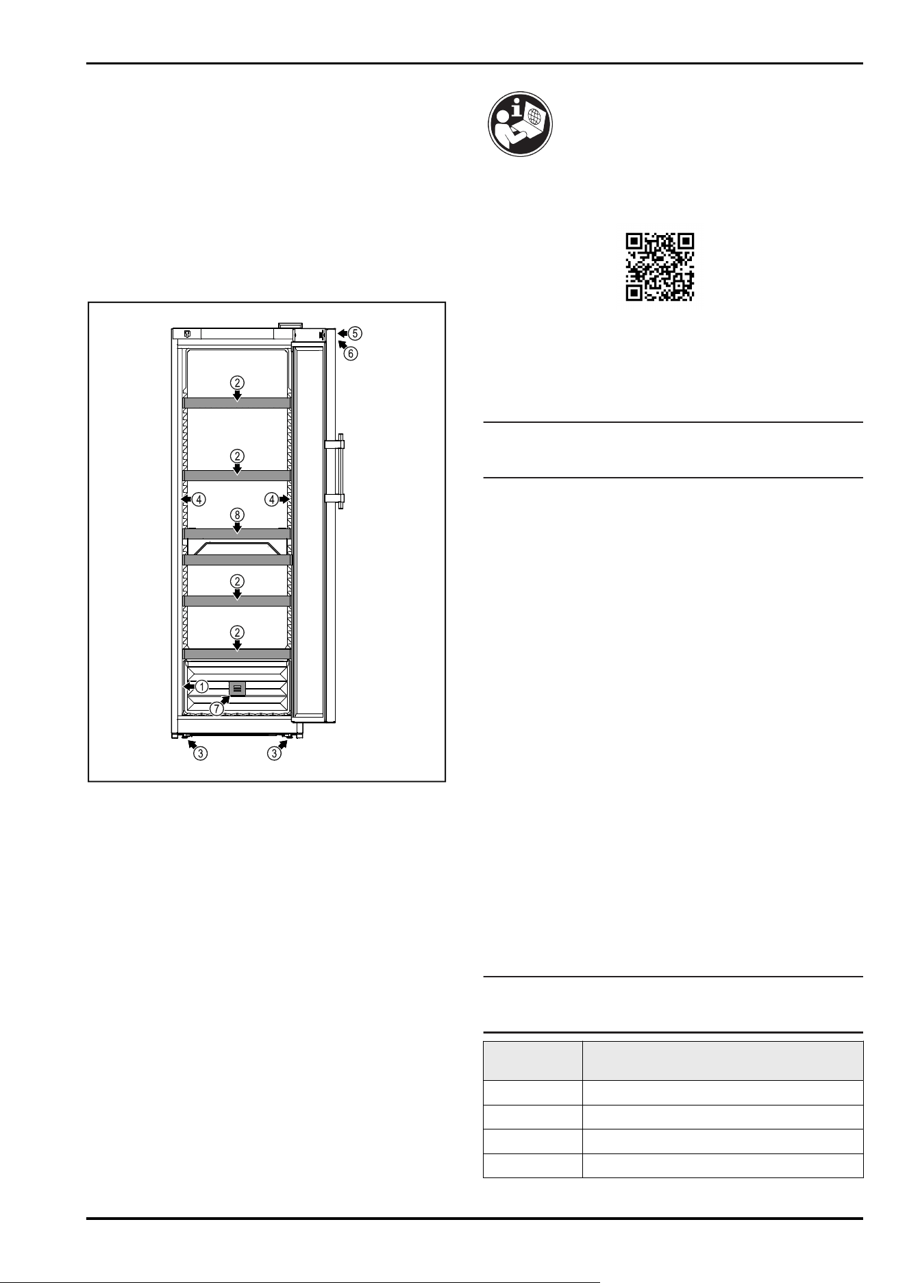
2.2 Overview of appliance and equip‐
ment
Fig. 1 Example illustration
(1)
Type plate (5) Lock
(2) Grid shelves (6) Control elements and
temperature display
(3) Adjusting feet (7) FreshAir activated char‐
coal filter
(4) Interior lighting (8) Bottle basket
2.3 SmartDevice
SmartDevice is the networking solution for your wine
storage cabinet.
If your appliance SmartDevice-enabled or compatible, you
can quickly and easily connect your appliance to your
WiFi. With the SmartDevice app, you can operate your appli‐
ance from a mobile device. Additional functions and setting
options are available in the SmartDevice SmartDevice app.
SmartDevice-
enabled appliance:
Your appliance is capable of being a
SmartDevice. To be able to connect
your device to WiFi, you need to
download the SmartDevice app.
More information
about SmartDe‐
vice:
smartdevice.liebherr.com
Downloading the
SmartDevice app:
After installing and configuring
the SmartDevice app, you can
connect your appliance to your Wi-Fi
(see 8.2.16 WiFi ) using the SmartDe‐
vice app and the appliance's Wi-Fi
function.
Note
The SmartDevice function is not available in the following
countries: Russia, Belarus, Kazakhstan.
2.4 Appliance range of use
Intended use
The appliance is only suitable for storing wine in a domestic
or domestic-like environment. This includes, for example,
using
-
in staff kitchens, bed and breakfast establishments,
-
by guests in country houses, hotels, motels and other
accommodation,
-
for catering and similar services in the wholesale trade.
The appliance is not suitable for freezing food;
The appliance is not suitable as a built-in unit.
All other types of use are not permitted.
Foreseeable misuse
The following applications are expressly forbidden:
-
Storing and refrigerating medicines, blood plasma, labo‐
ratory preparations or similar substances and products
based on the Medical Device Directive 2007/47/EC
-
Use in outdoor areas with very high humidity
-
Use in areas at risk of explosions
Misusing the appliance may lead to damage to the goods
stored or they may spoil.
Climate classifications
Depending on the climate classification the appliance is
designed to operate in restricted ambient temperatures. The
climate classification applying to your appliance is printed
on the rating plate.
Note
► Keep to the specified ambient temperatures in order to
guarantee that the appliance works properly.
Climate clas‐
sification
for ambient temperatures of
SN 10°C to 32°C
N 16°C to 32°C
ST 16°C to 38°C
T 16°C to 43°C
Appliance at a glance
4 * Depending on model and options
Climate clas‐
sification
for ambient temperatures of
SN-ST 10°C to 38°C
SN-T 10°C to 43°C
2.5 Conformity
The refrigerant circuit has been tested for leaks. The appli‐
ance complies with the applicable safety regulations and
with the corresponding directives.
For the EU
market:
The appliance complies with directive
2014/53/EU.
For the GB
market:
The appliance complies with Radio
Equipment Regulations 2017 SI 2017 No.
1206.
The full text of the EU Declaration of Conformity is available
on the following website: www.Liebherr.com
The BioFresh compartment meets the requirements of a
cold storage compartment as set out in DIN EN 62552:2020.
2.6 SVHC substances according to
REACH regulation
You can check whether your appliance contains SVHC
substances according to REACH regulation at the following
link: home.liebherr.com/de/deu/de/liebherr-erleben/nach‐
haltigkeit/umwelt/scip/scip.html
2.7 EPREL database
Details about energy labelling and ecodesign requirements
will be available on the European product database (EPREL)
from 1st March 2021. You can access the product database
at the following link: https://eprel.ec.europa.eu/ You will be
asked to enter the model ID. You can find the model ID on
the nameplate.
2.8 Spare parts
The spare parts availability for functional parts and stock‐
able parts of the equipment is 15 years.
3 Setting up and connecting
3.1 Installation requirements
The installation conditions are crucial to ensure that you
can operate your appliance safely, efficiently and without
problems.
-
Observe all safety instructions.
-
Consider the location and position in the room.
WARNING
Danger of fire due to incorrect positioning!
► Make sure the mains cable is not trapped under the appli‐
ance when you position the appliance.
► Position the appliance so that it does not touch the plug
or mains cable.
► Do not connect any appliances to sockets in the area of
the back of the appliance.
► Do not place and operate multi-sockets/power distribu‐
tors and other electronic devices (such as halogen trans‐
formers) at the back of the appliances.
WARNING
Fire hazard due to dampness!
If live parts or the mains lead become damp this may cause
short circuits.
► The appliance is designed for use in enclosed areas. Do
not operate the appliance outdoors or in areas where it is
exposed to splash water or damp conditions.
WARNING
Leaking coolant and oil!
Fire. The coolant contained in the appliance is eco-friendly,
but also flammable. The oil contained in the appliance
is flammable. Escaping coolant and oil can ignite if the
concentration is high enough and in contact with an
external heat source.
► Do not damage the pipelines of the coolant circuit and
the compressor.
3.1.1 Installation site
-
A dry and well-ventilated room is an optimum installation
location.
-
If the appliance is installed in a very damp environment,
condensation may form on the appliance exterior.
Always make sure there is good ventilation and aeration
at the installation site.
-
The more refrigerant there is in the appliance, the larger
than room must be in which it is located. In rooms that
are too small, a leak can product a flammable gas/air
mixture. For every 8g of refrigerant, the installation room
must be at least 1 m
3
in size. Information on the refrig‐
erant contained is given on the type plate inside the
appliance.
-
The floor on which the appliance stands must be hori‐
zontal and level.
3.1.2 Position in space
-
Do not place the appliance in direct sunlight or near radi‐
ators or similar sources of heat.
-
Always position the appliance with the rear directly on
the wall.
-
Use in hazardous areas is not permitted.
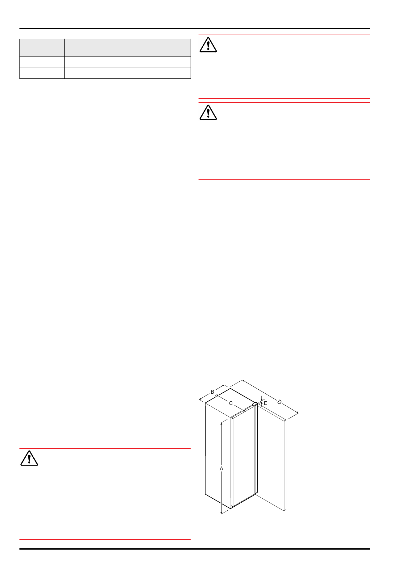
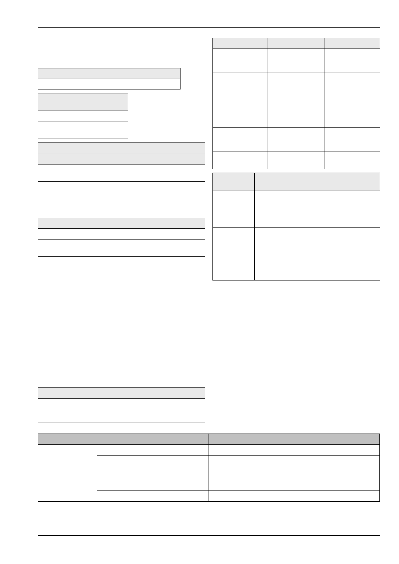
3.2 Appliance dimensions
Setting up and connecting
* Depending on model and options 5
A B C D E
WFbli
5041
1684mm 600mm 763mm 1323mm 23mm
WFbli 5241 1884mm 600mm 763mm 1323mm 23mm
WFbli 7741 2044mm 750mm 763mm 1473mm 23mm
A = appliance height including feet/castors/hinges
B=appliance width without handle
C = appliance depth without handle
D = appliance depth with door open
E = hinge height
3.3 Transporting the appliance
WARNING
Risk of injury due to broken glass!
When transporting at an altitude of more than 1500 m, the
glass panes of the door may break. This can result in sharp-
edged fragments, which can cause serious injuries.
► Take appropriate protective action.
3.3.1 Transporting the appliance for initial use
Ensure that the following requirements are met:
❑
The appliance is packaged.
❑
The appliance is upright.
► Transport the appliance with the help of two people.
► Unpacking the appliance. (see 3.4 Unpacking the appli‐
ance)
3.3.2 Transporting the appliance after initial
use
Observe the following instructions if you wish to transport
or move the appliance again after initial use.
Ensure that the following requirements are met:
❑
The appliance is emptied.
❑
The appliance is upright.
❑
Door is secured against accidental opening.
❑
The pull-out trolley is secured against accidental
opening.
► Transport the appliance with the help of two people.
After transport:
► Unscrew the adjustable feet on the appliance.
► Align the appliance.
3.4 Unpacking the appliance
Before you connect the appliance, report any damage imme‐
diately to the delivery company.
► Check the appliance and the packaging for damage
during transport. Contact the supplier immediately if you
suspect any level of damage.
► Remove all materials from the back or the side walls
of the appliance that may prevent proper installation or
ventilation.
► Remove all protective films from the appliance. Do not
use sharp or pointed objects for this.
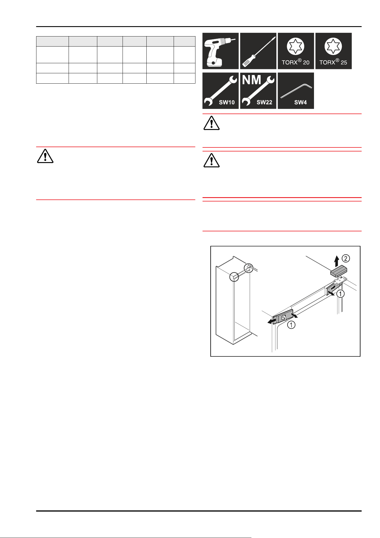
3.5 Reversing the door opening direc‐
tion
Tools
WARNING
Risk of injury if the door is not reversed correctly!
► Replace the door hinge with specialist personnel.
WARNING
Risk of injury and material damage due to heavy door!
► Only perform the conversion if you can carry a weight of
25 kg.
► Always have someone help you carry out the conversion.
NOTICE
Live parts!
Damage to electrical components.
► Remove the mains plug before you reverse the door.
► Open the door.
Fig.2
► Unlatch the front covers Fig. 2 (1) on the inside and
remove them sideways.
► Lift off the upper cover Fig.2(2).
Setting up and connecting
6 * Depending on model and options
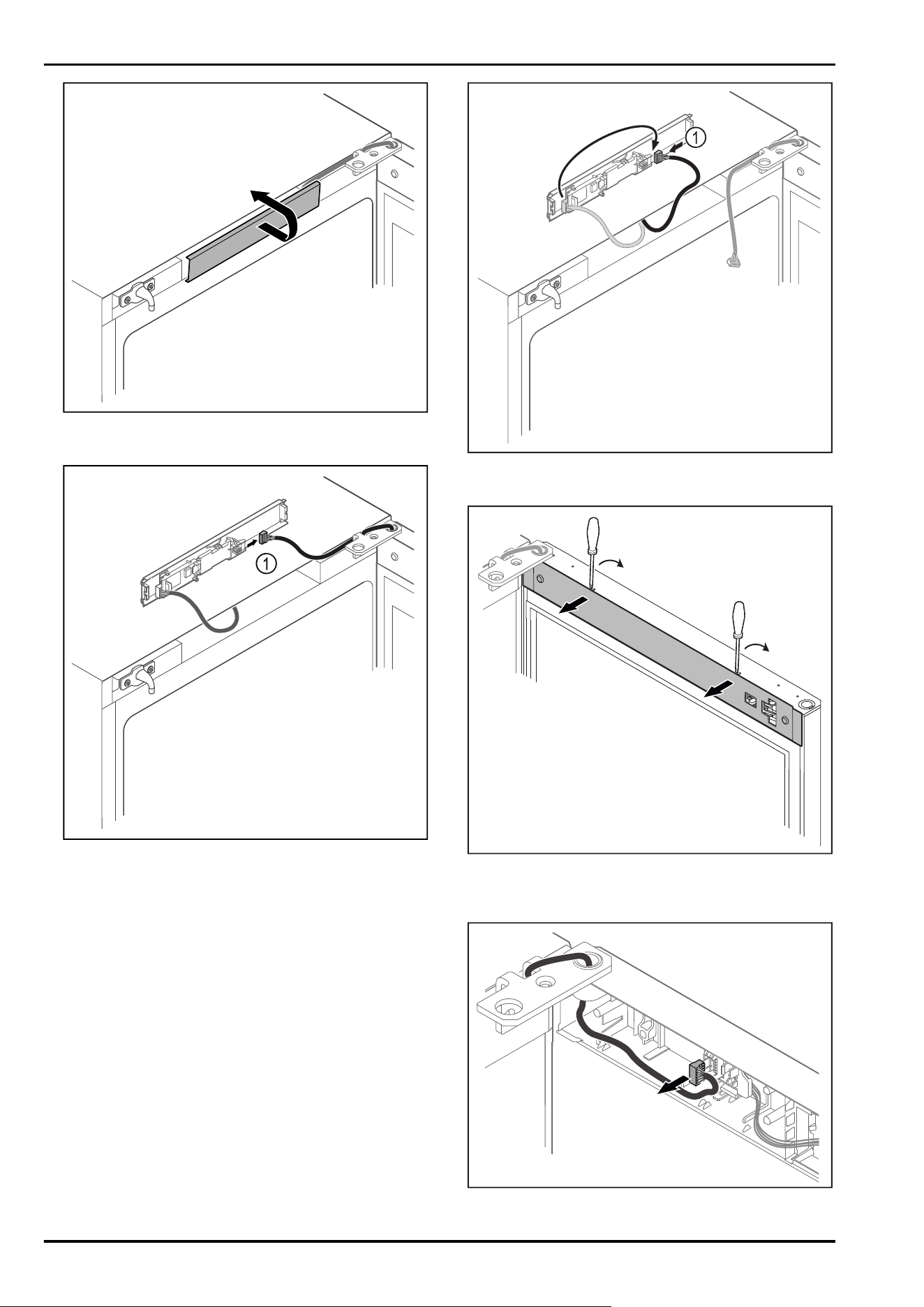
Fig.3
► Unlatch the middle cover and remove it.
Fig.4
► Disconnect the plug Fig.4(1) from the circuit board.
Fig.5
► Connect the plug Fig.5(1) to the circuit board.
Fig.6
► Unlatch the cover with a small screwdriver and take it
off.
Fig.7
Setting up and connecting
* Depending on model and options 7
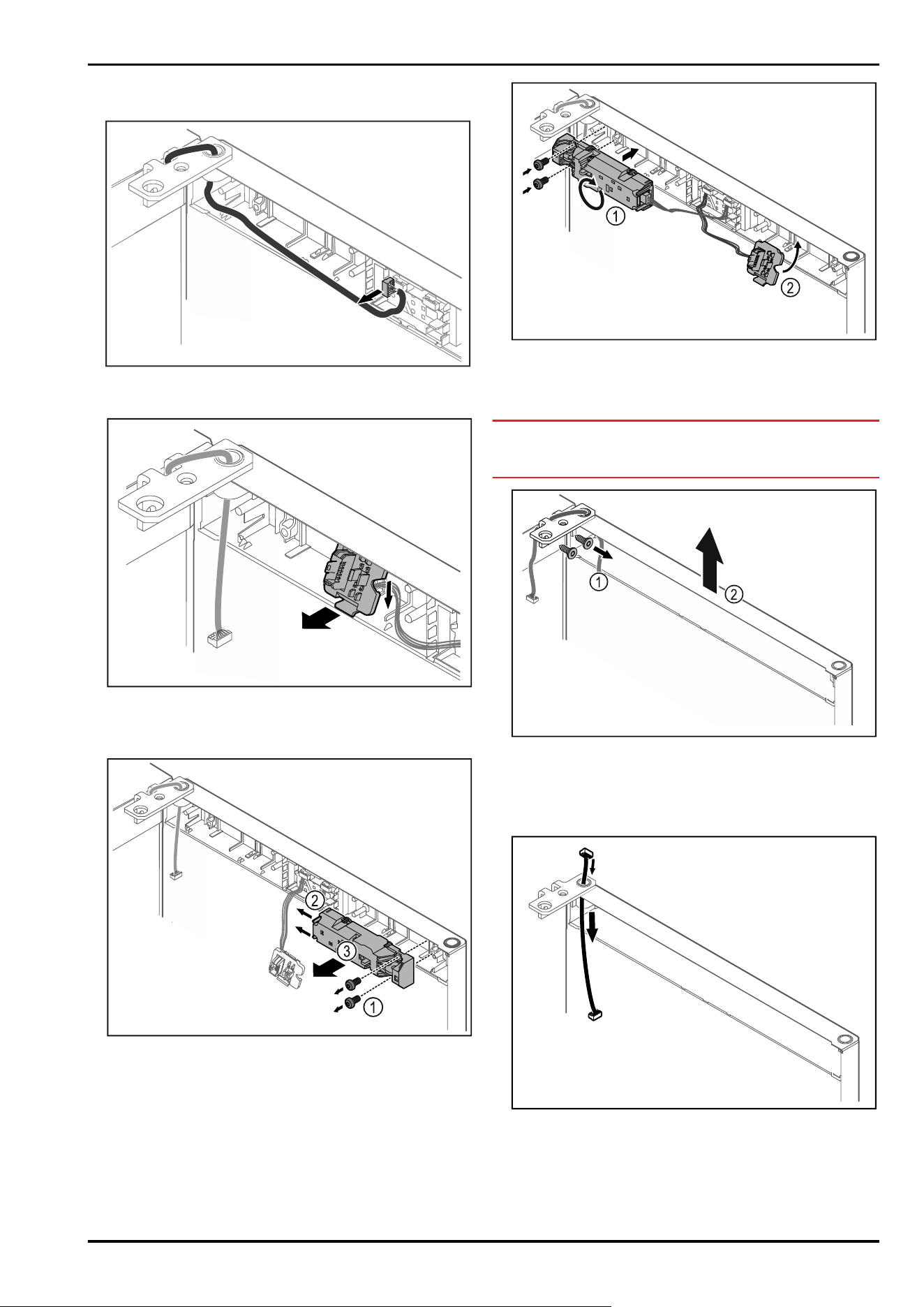
► Remove the plug from the plug holder.
-or-
Fig.8
► Remove the plug from the circuit board.
Fig. 9 The installation position for the plug holder can be
rotated by 180°.*
► Unlatch the plug holder.*
Fig. 10
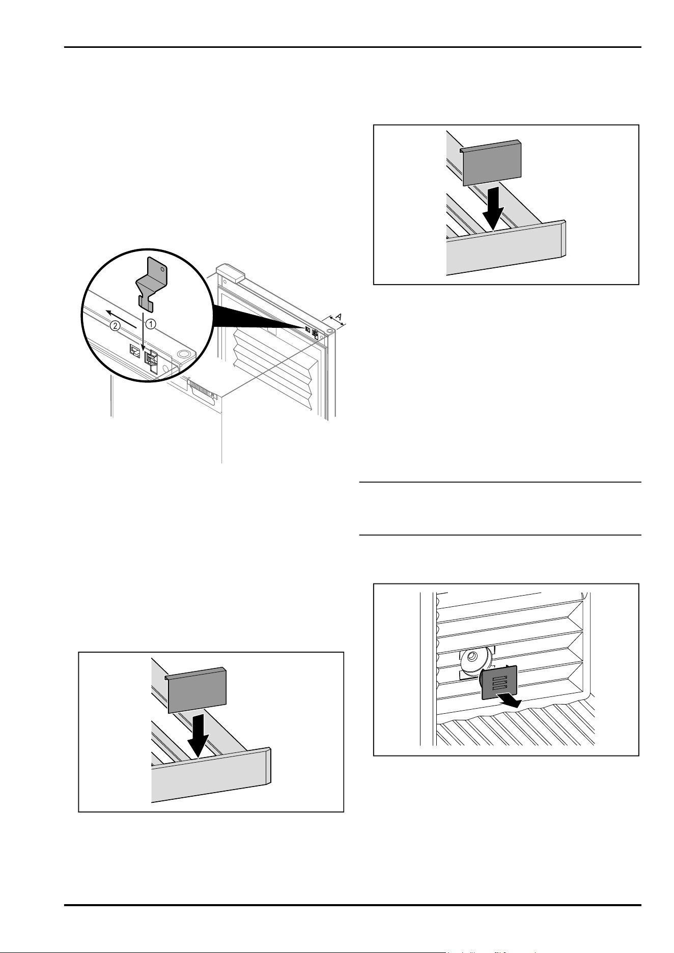
► Remove the screws Fig. 10(1).
► Press the latching lugs Fig. 10 (2) to the side and take off
the remote lock Fig. 10(3).
Fig.11
► Turn the remote lock Fig. 11 (1) by 180° and fasten it on
the opposite side.
► Engage the plug holder Fig.11(2) on the opposite side.*
NOTICE
Risk of injury if the door tips out!
► Hold the door.
Fig.12
► Unscrew the hinge Fig.12(1).
► Lift the door with the hinge straight up by Fig. 12 (2)
roughly 200mm and take it off.
► Carefully place the door on a soft surface.
Fig.13
► Carefully pull out the cable.
Setting up and connecting
8 * Depending on model and options
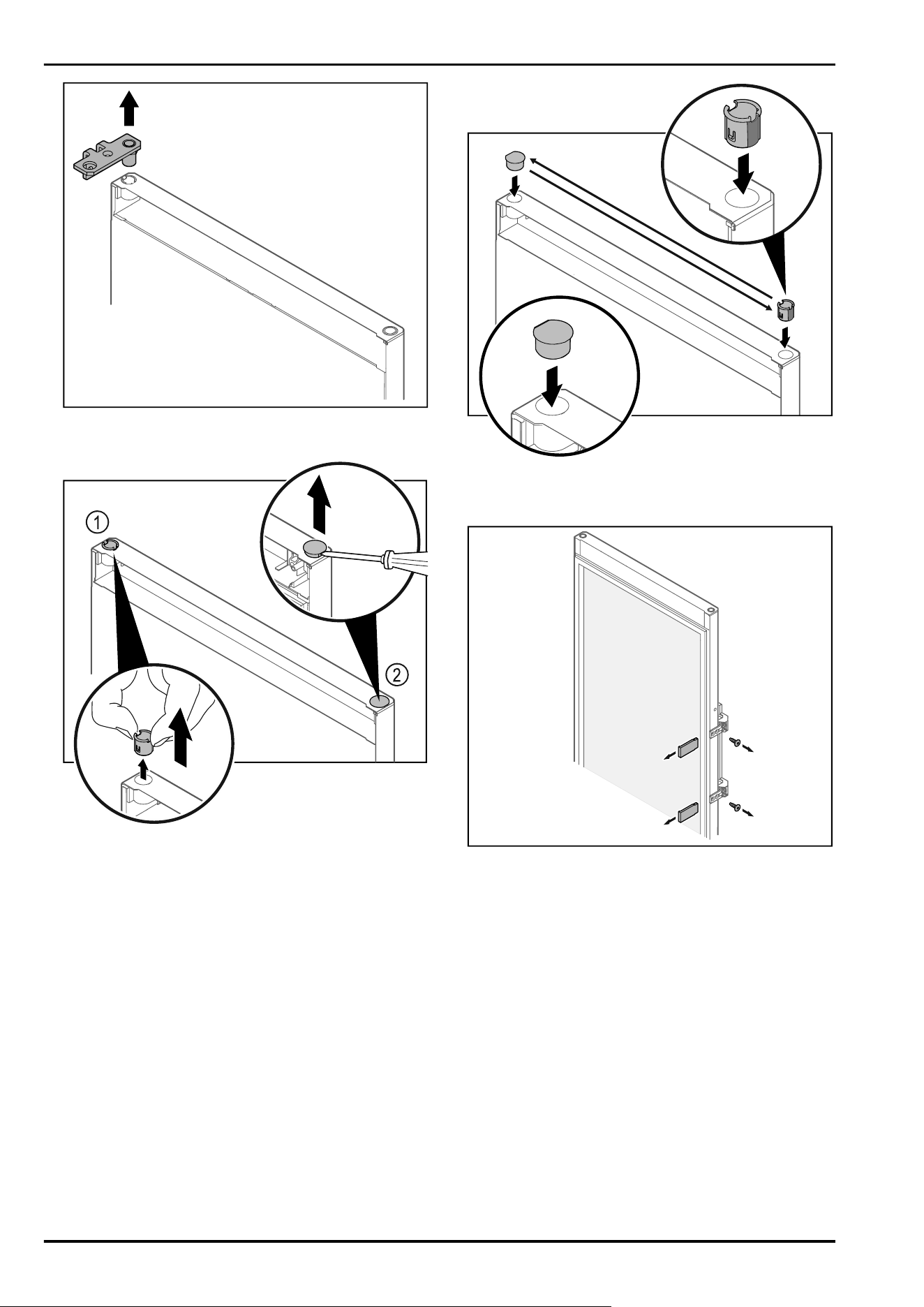
Fig. 14
► Pull out the hinge.
Fig. 15
► Pull out the hinge bushing Fig. 15(1) with your fingers.
► Carefully lift the cover plug Fig. 15 (2) with a slotted
screwdriver and pull it out.
Fig. 16
► Insert hinge bushing and cover plug on the opposite side
(the flattened sides face outwards).
Fig.17Glass door
► Remove the panels.
► Unscrew the handle.
Setting up and connecting
* Depending on model and options 9
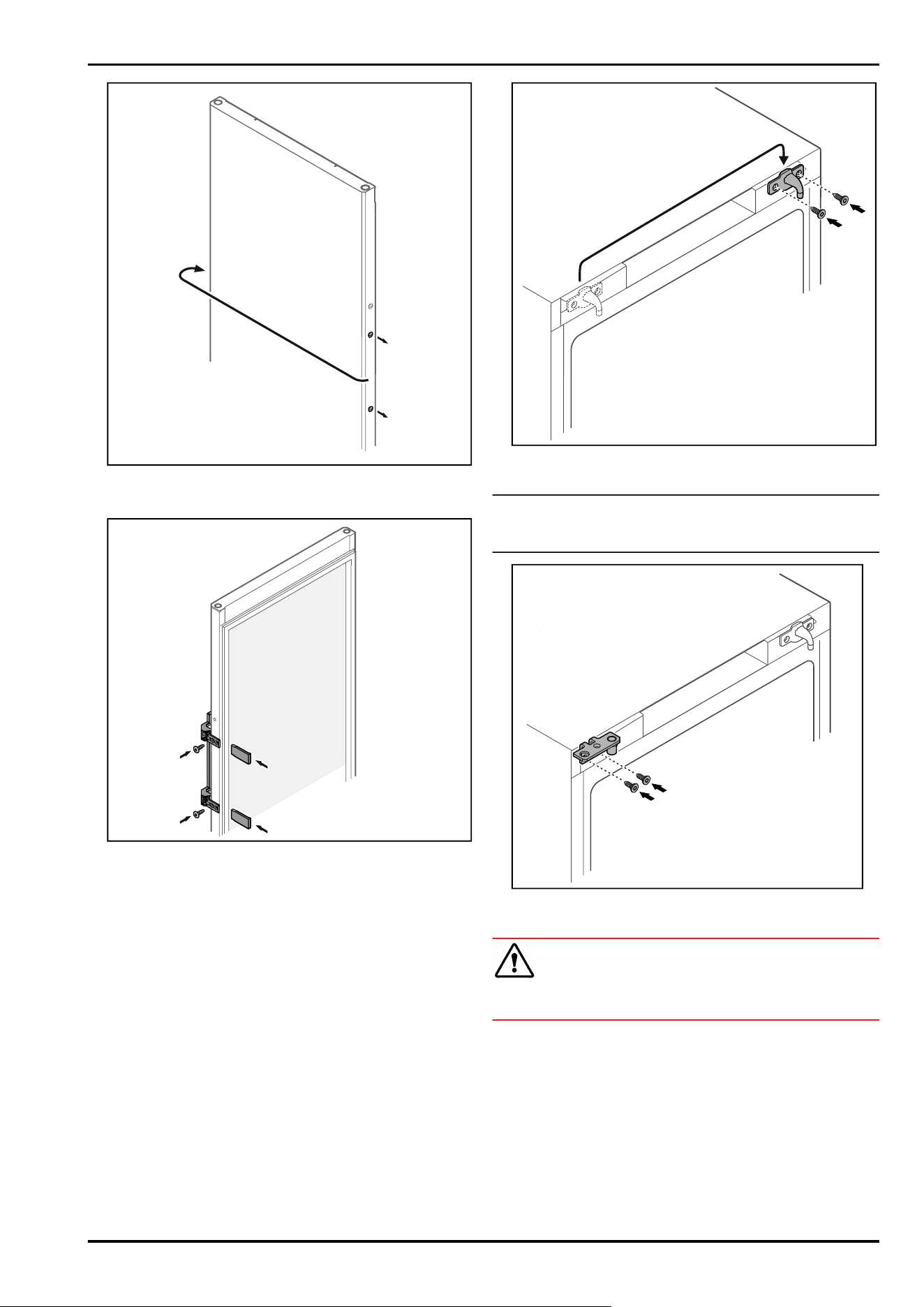
Fig. 18
► Put the stopper on the opposite side.
Fig. 19Glass door
► Screw the handle onto the opposite side.
► Attach the panels.
Fig.20
► Move the door latch to the opposite side.
Note
The holes are pre-marked and must be pierced with the
self-tapping screws.
Fig.21
► Move the hinge to the opposite side.
WARNING
Risk of injury and material damage if the door tips out!
► Tighten the bearing pins to the specified torque.
Setting up and connecting
10 * Depending on model and options
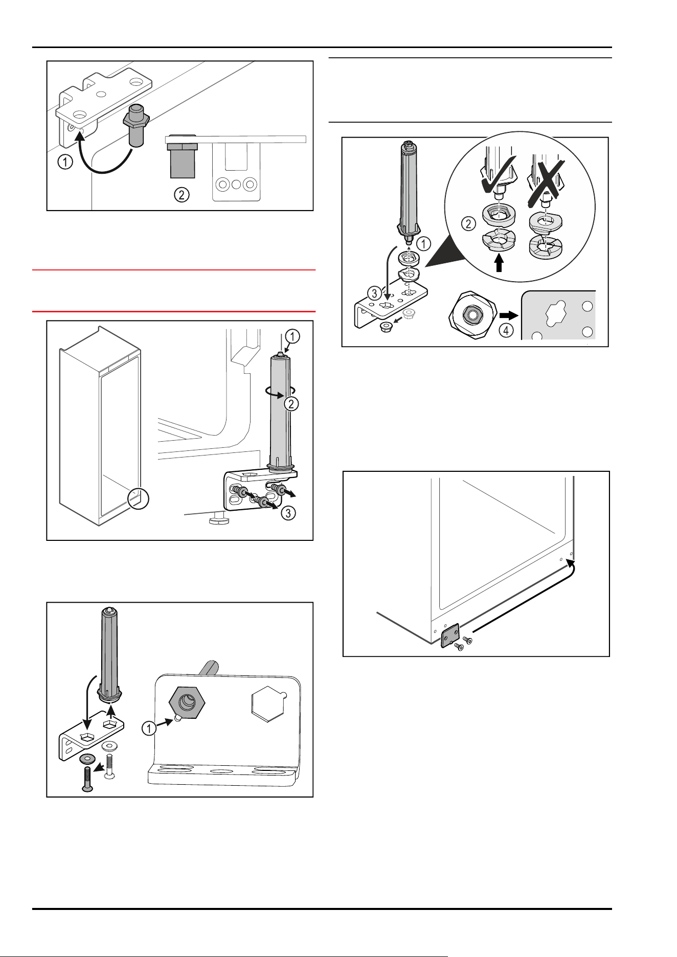
Fig.22
► Put the pin back into the hinge Fig.22(1).
► Tighten the pin Fig.22(2) to a torque of 12 Nm.
► Unscrew the hinge again.
NOTICE
Risk of injury due to tensioned spring!
► Do not disassemble the door closing system Fig.23(1).
Fig.23
► Turn the closing system Fig.23(2) until it clicks.
▷ The tension of the closing system is released.
► Unscrew the hinge Fig.23(3).
Fig. 24
► Put the door closing system in the hinge.
► Make sure the pin chamfer Fig. 24(1) faces the round hole
when you put it in.
-or-
Note
Incorrect alignment of the height adjustment washers.
Nuts no longer have sufficient hold.
► The washer must lock into the underside of the closing
system.
Fig.25
► Loosen the nut and remove the door closing system
Fig.25(1).
► Observe the correct alignment of the height adjustment
washers Fig.25(2).
► Put the door closing system in the hinge and fix in place
with the nut Fig.25(3).
► Observe the correct alignment of the door closing system
when doing so Fig.25(4).
Fig. 26
► Put the cover plate on the opposite side.
Setting up and connecting
* Depending on model and options 11
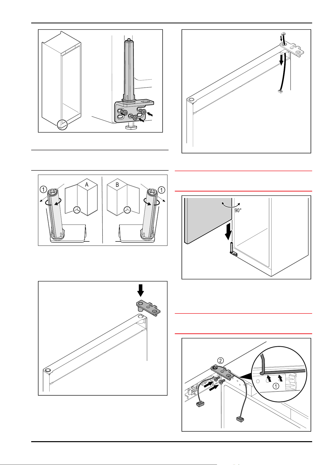
Fig.27
► Screw the hinge onto the opposite side.
Note
Correct alignment and tension are important for the closing
system to work properly.
Fig. 28 Left-hinged (A) / Right-hinged (B)
► Turn the closing system against the resistance until the
bar of the closing system Fig.28(1) points outwards.
▷ The closing system automatically stays in this position.
▷ The closing system is now aligned and tensioned.
Fig.29
► Put the hinge into the door.
Fig.30
► Carefully push the cable through.
NOTICE
Risk of injury if the door tips out!
► Hold the door.
Fig.31
► Together with a second person, lift the door from the
ground.
► Carefully put the door on the closing system with the
door opened at a 90° angle.
NOTICE
Material damage due to incorrect mounting!
► Do not pinch the cable when mounting the hinge.
Setting up and connecting
12 * Depending on model and options
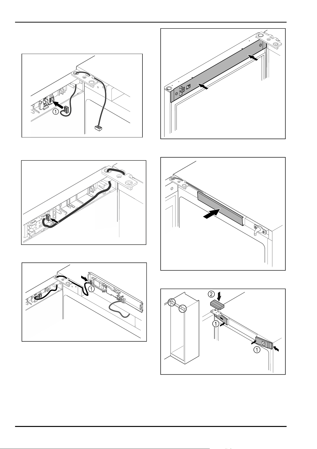
Fig.32
► Feed the cable through the recess in the hinge and lay it
carefully Fig.32(1).
► Screw on the hinge Fig.32(2).
Fig.33
► Put the plug Fig.33(1) in the plug holder.
-or-
Fig.34
► Plug the connector into the circuit board.
Fig.35
► Connect the plug Fig.35(1) to the circuit board.
Fig.36
► Put on the cover.
Fig.37
► Snap in the middle cover.
Fig.38
► Hook in the front covers Fig. 38 (1) on the side and snap
them into place.
► Snap on the top cover Fig.38(2) from above.
► Close the door.
▷ The door has now been reversed.
Setting up and connecting
* Depending on model and options 13
3.6 Aligning the door
If the door is not straight, you can adjust it on the lower
hinge.
Fig. 39
► Remove the middle screw on the lower hinge.
Fig.40
► Slightly undo both screws and move the door with the
hinge to the left or right.
► Fully tighten the screws (the middle screw is no longer
needed).
▷ The door is now straight.
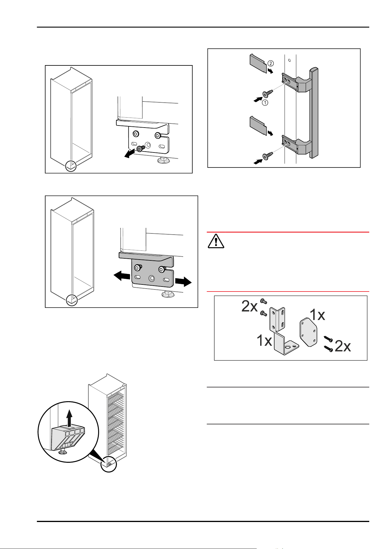
3.7 Removing transport lock
Fig. 41
► Remove transport lock in upwards direction.
▷ Base holder remains on the appliance.
3.8 Installing door handle
Fig. 42
► Attach handle from accessory kit to the door using the
screws Fig. 42(1) supplied.
► Put on cover Fig. 42(2).
► Insert the plug from the accessory pack on the opposite
side. *
3.9 Mounting anti-tipping device
WARNING
Danger of injury and damage due to appliance tipping over!
Danger to life and material damage to the appliance. An
appliance without an anti-tip device fitted can tip over if you
open the door or pull out shelves, for example.
► Before putting the appliance into operation: Always fit
the anti-tilt device according to the instructions.
Fig.43
The anti-tipping device is included with the appliance. It
comprises a retaining part, a bracket and four screws.
Note
The anti-tipping device must be installed on the left or right-
hand side, as viewed from the rear. The following images
are labelled left (L) or right (R) depending on where the
anti-tipping device is installed.
Setting up and connecting
14 * Depending on model and options
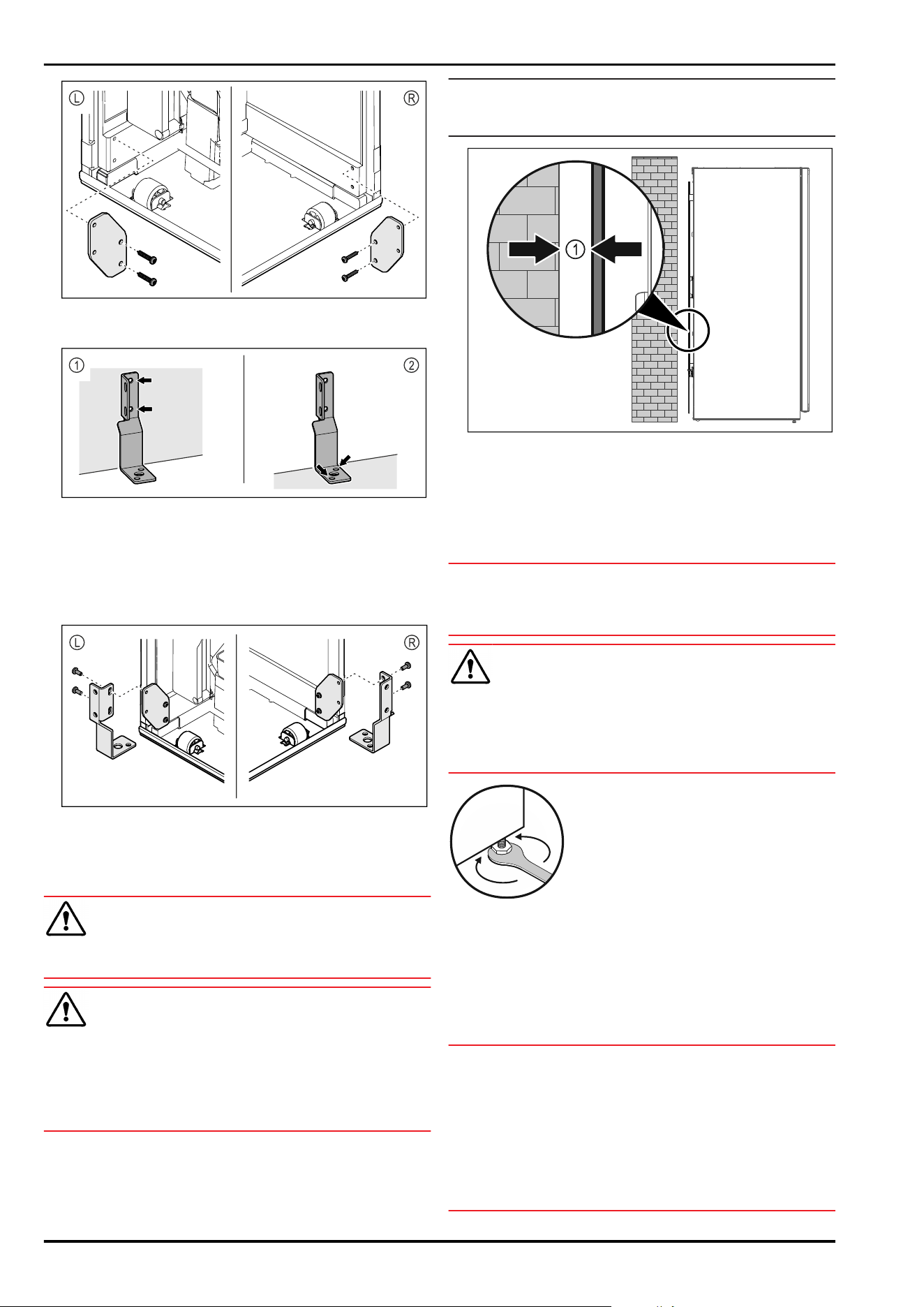
Fig.44
► Mount retaining part on appliance using screws supplied.
Fig.45
Use fixing material (e.g. dowels) which is appropriate
for the nature of the wall or floor (wood, concrete) and
sufficient attachment points.
► Attach bracket to wall Fig.45(1) or floor Fig.45(2).
► Slide in appliance and align with bracket.
(see 3.11 Setting up the appliance so it is level)
Fig.46
► Screw bracket and retaining part together.
3.10 Installing appliance
CAUTION
Risk of injury and damage.
► Use 2 people to install appliance.
CAUTION
Risk of injury and damage.
The door can knock against the wall and become damaged
as a result. In the case of glass doors, the damaged glass
can cause injuries.
► Protect the door from knocking against the wall. Attach
door stopper, e.g. felt stopper, to the wall.
► Connect all necessary components (e.g. mains cable) to
the back of the appliance and route to the side.
Note
Cables can be damaged.
► Do not jam the cable when pushing the appliance back.
Fig. 47
► Set up the appliance either free-standing or directly
against a wall at a minimum distance of 5mm Fig. 47(1).
3.11 Setting up the appliance so it is
level
NOTICE
Appliance body is deformed and door does not close.
► Align appliance horizontally and vertically.
► Compensate for uneven floors using adjustable feet.
WARNING
Incorrect height adjustment of the adjustable foot!
Can cause severe or even fatal injury. Incorrect height
adjustment can cause the bottom part of the adjustable
foot to come loose and the appliance to tip over.
► Do not unscrew the adjustable foot too far.
Fig.48
Raising appliance:
► Turn adjustable foot clockwise.
Lowering appliance:
► Turn adjustable foot anticlockwise.
3.12 Installing multiple appliances
NOTICE
Risk of damage due to condensation between the side
walls.
► Do not install the appliance directly next to another
fridge.
► Install appliances with a space 3cm between appliances.
► Only install multiple appliances up to temperatures of
35°C and 65% humidity next to one another.
► At higher levels of humidity, increase space between
appliances.
Setting up and connecting
* Depending on model and options 15
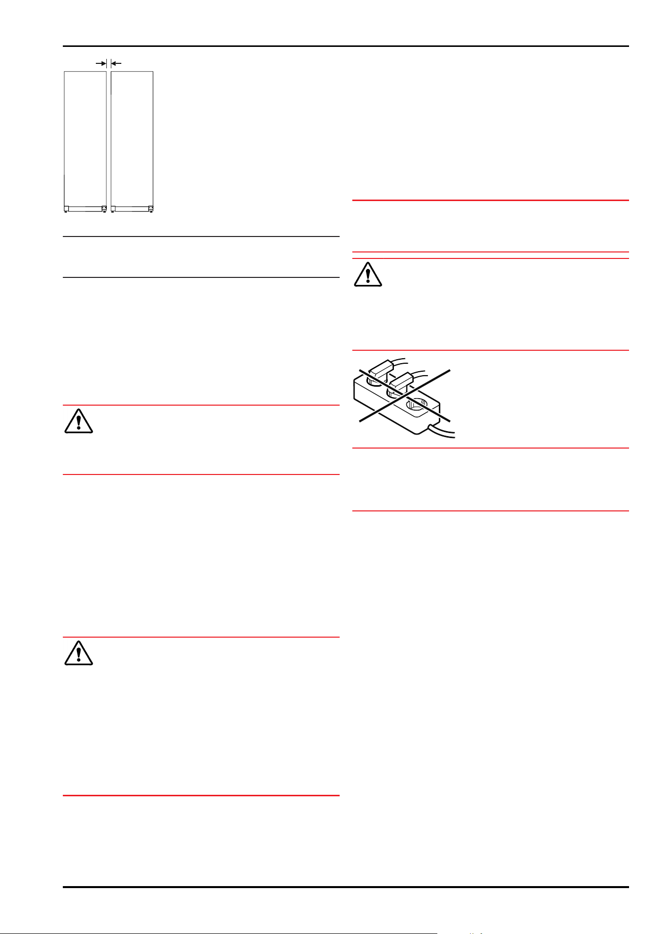
Fig. 49 Side-by-side installation
Note
A side-by-side kit is available as an accessory via Liebherr
Customer Service. (see11.4 Customer Service)
3.13 After installation
► Peel off the protective films. *
► Clean appliance. (see 10.2Cleaning the appliance)
► If necessary: Disinfect the appliance.
► Keep the invoice so you have the appliance and dealer
information available if needed.
3.14 Disposing of packaging
WARNING
Danger of suffocation due to packing material and plastic
film!
► Do not allow children to play with packing material.
The packaging is made of recyclable materials:
-
corrugated board/cardboard
-
expanded polystyrene parts
-
polythene bags and sheets
-
polypropylene straps
-
nailed wooden frame with polyethylene panel*
► Take the packaging material to an official collecting
point.
3.15 Connecting the appliance to the
power supply
WARNING
Danger of electric shock and injury due to damaged appli‐
ance or damaged mains cable!
Danger of cuts and fatal injuries. If the appliance or the
mains cable is damaged during transport, you may be elec‐
trocuted. You could also cut yourself on damaged parts of
the appliance housing.
► Check the appliance and the mains cable for damage
after transport.
► Never put the appliance into operation if the appliance or
the mains cable are damaged.
► Contact Customer Service.
You can connect your appliance to the mains using the
power cable supplied separately. The mains power cable
has an appliance coupler at one end and a mains plug at the
other end.
Make sure that the following requirements are fulfilled:
-
The appliance and power cable are undamaged.
-
The appliance is set up in accordance with the regula‐
tions. (see 3.7 Removing transport lock)
-
Requirements for the electrical connection are met.
-
Dimensions for connection in accordance with regula‐
tions are known and observed.
-
Mains voltage and frequency correspond to the specifica‐
tions on the type plate.
-
The socket is earthed according to the regulations and
fused.
-
The fuse tripping current is between 10A and 16A.
-
The socket is easily accessible and is not behind the
appliance.
NOTICE
Danger of damage to incorrect operation!
Damage to the electrical components of the appliance.
► Only use the supplied mains cable.
WARNING
Danger of fire due to incorrect connection!
Burns.
Damage to the appliance.
► Do not use an extension cable.
► Do not use distributor blocks.
NOTICE
Danger of damage to incorrect connection!
Damage to the appliance.
► Do not connect the appliance to a stand-alone inverter,
e.g. solar power systems and petrol generators.
► Connect the mains cable plug to the power supply.
Ensure that the plug is tightly in the socket.
▷ The standby symbol appears in the display.
▷ If no action occurs within 60 seconds: The standby
symbol fades or disappears.
▷ The appliance is connected. For information regarding
first use, see the following section or the operating
instructions.
4 Functionality of the
Touch&Swipe display
You operate your appliance using the Touch & Swipe display.
You select appliance functions in the Touch & Swipe display
(hereafter referred to as display) by tapping them. If you
do not perform any action on the display for 10 seconds,
the display either jumps back to the higher-level menu or
directly to the status display.
4.1 Navigation and symbol explanation
In the illustrations, different symbols are used to navigate
the display. The following table describes these symbols.
Functionality of the Touch&Swipe display
16 * Depending on model and options
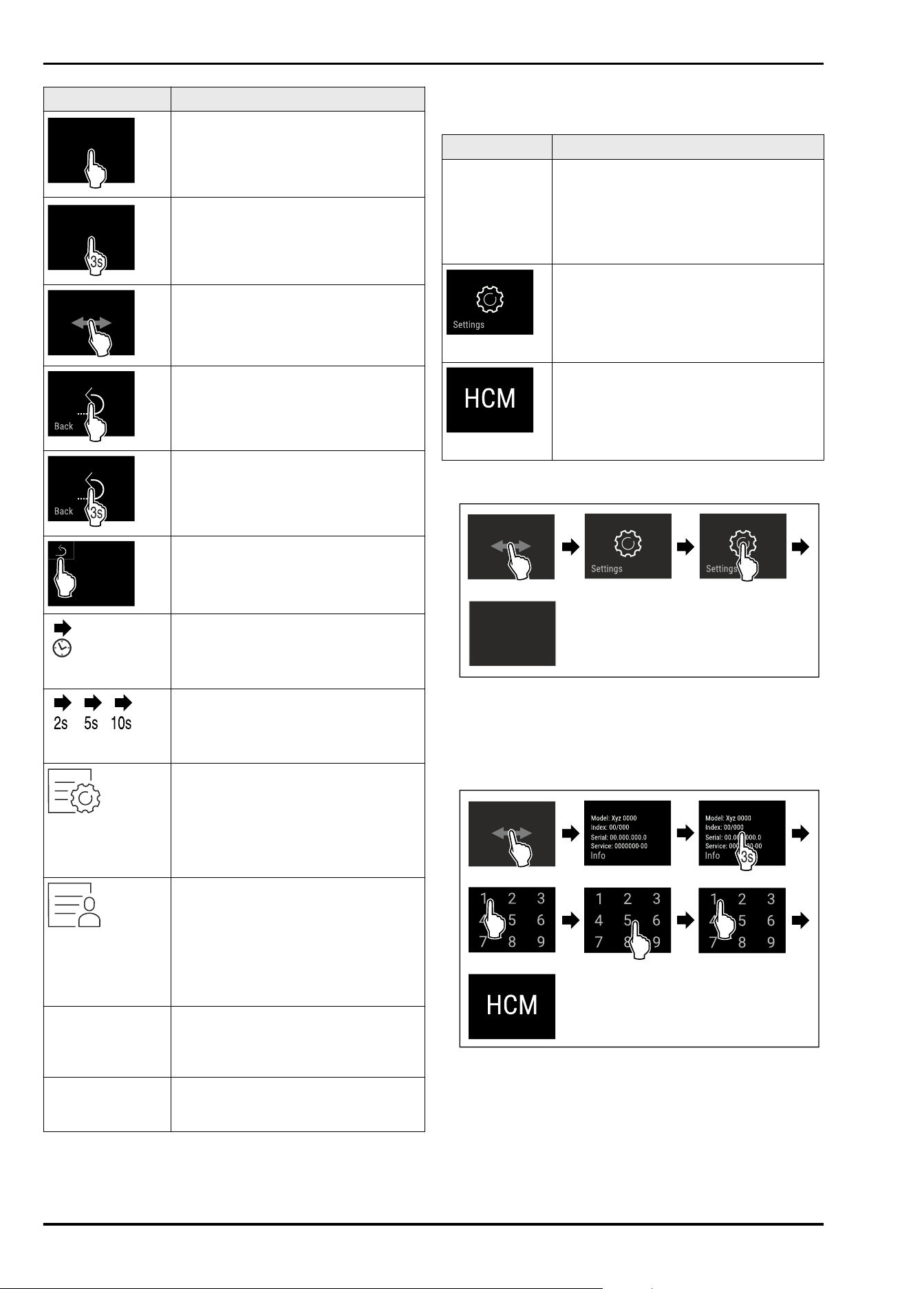
Symbol Description
Briefly touch the display:
Activates/deactivates function.
Confirms selection.
Opens submenu.
Touch the display for a specified time
(e.g. 3seconds):
Activates/deactivates function or
value.
Swipe left or right:
Navigate in the menu.
Briefly touch the Back symbol:
Jumps back one menu level.
Press and hold the Back symbol for
3seconds:
Jumps back to the status display.
Briefly touch the Back symbol at the
top left:
Jumps back one menu level.
Arrow with clock:
It takes more than 10 seconds for the
following message to appear in the
display.
Arrow with a time indication:
It takes the specified amount of time
until the following message appears in
the display.
“Open Settings menu” symbol:
Navigates to the Settings menu and
opens the settings menu.
If necessary: Navigate to the desired
function in the Settings menu.
(see4.2.1 Opening the Settings menu)
“Open Advanced menu” symbol:
Navigates to the Advanced menu and
opens the advanced menu.
If necessary: Navigate to the desired
function in the Advanced menu.
(see 4.2.2 Opening the expanded
menu)
No action for
10seconds
If you do not perform any action on
the display for 10 seconds, the display
either jumps back to the higher-level
menu or directly to the status display.
Open door and
close it again.
If you open the door and immedi‐
ately close it again, the display jumps
directly back to the status display.
Note: Illustrations of the display are shown in the English
version.
4.2 Menus
The appliance functions are distributed over various menus:
Menu Description
Main menu When you switch the appliance on, you
are automatically in the main menu.
From here you can navigate to the most
important appliance functions, to the
Settings menu and to the Advanced
menu.
Settings menu
The Settings menu contains additional
appliance functions for setting up your
appliance.
Advanced menu
The advanced menu contains special
appliance functions for setting up your
appliance. Access to the Advanced menu
is protected by the numerical code 151.
4.2.1 Opening the Settings menu
Fig. 50 Example illustration
► Carry out action steps according to the illustration.
▷ Settings menu is open.
► If necessary: Navigate to the desired function.
4.2.2 Opening the expanded menu
Fig.51Access with numerical code 151
► Carry out action steps according to the illustration.
▷ The expanded menu is open.
► If necessary: Navigate to the desired function.
Functionality of the Touch&Swipe display
* Depending on model and options 17
4.3 Sleep mode
If you do not touch the display for 1 minute, the display
switches to sleep mode. In sleep mode, the display bright‐
ness is dimmed.
4.3.1 Ending sleep mode
► Touch the display briefly with your finger.
▷ Sleep mode is ended.
5 Putting into operation
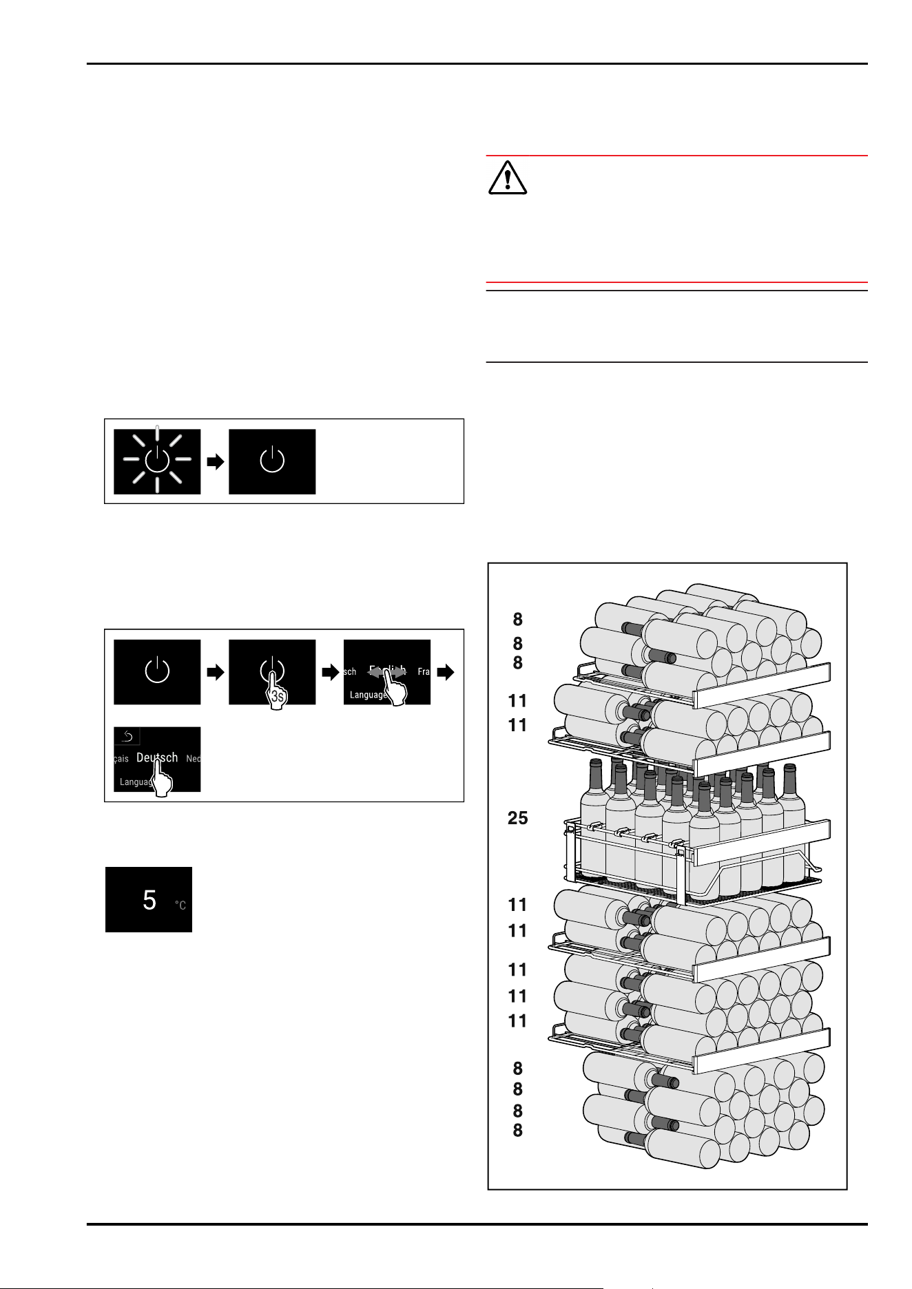
5.1 Switching on appliance (first use)
Ensure that the following requirements are met:
- Appliance is installed and connected.
- All adhesive strips, adhesive and protective films and
transport locks are removed from inside and outside the
appliance.
Fig. 52 Example illustration
► The standby symbol is flashing: Wait until the start
process is complete.
▷ The display shows the standby symbol.
If the appliance has been supplied with factory settings,
the screen language and the date/time first need to be set
when using the appliance for the first time.
Fig.53
► Carry out action steps according to the illustration.
▷ Language is set.
Fig. 55 Status display
▷ The appliance is ready for operation once the tempera‐
ture appears in the display.
▷ The temperature display flashes until the set tempera‐
ture is reached.
6 Storage
6.1 Information regarding storage
WARNING
Fire hazard from electrical appliances!
If you use electrical appliances in the food area of your
appliance, they can cause a fire.
► Do not use electrical appliances in the food area of the
appliance unless recommended by the manufacturer.
Note
The energy consumption increases and the cooling power
goes down if ventilation is not sufficient.
► Always keep air slots clear.
Observe the following specifications for storage:
-
Keep the air vents on the fan free.
-
Keep liquids in closed containers.
-
Position storage shelves according to the height required.
-
Observe maximum load weight. (see 11.1 Technical speci‐
fications)
6.2 Storage diagram
6.2.1 WF 50
Putting into operation
18 * Depending on model and options
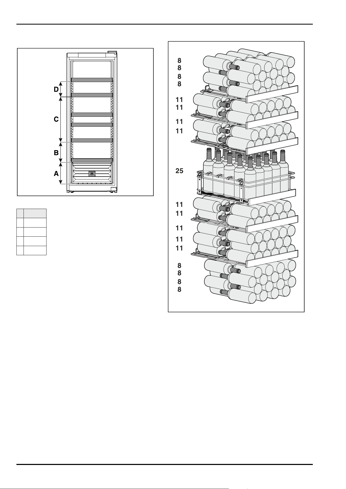
Fig. 56 Total 158 bottles (0.75 l Bordeaux bottles as per
standard NF H 35-124)
Fig.57Grid shelf spacing
WF 50
A 260mm
B 240mm
C 540mm
D 180mm
6.2.2 WF 52
Fig. 58 Total 188 bottles (0.75 l Bordeaux bottles as per
standard NF H 35-124)
Storage
* Depending on model and options 19
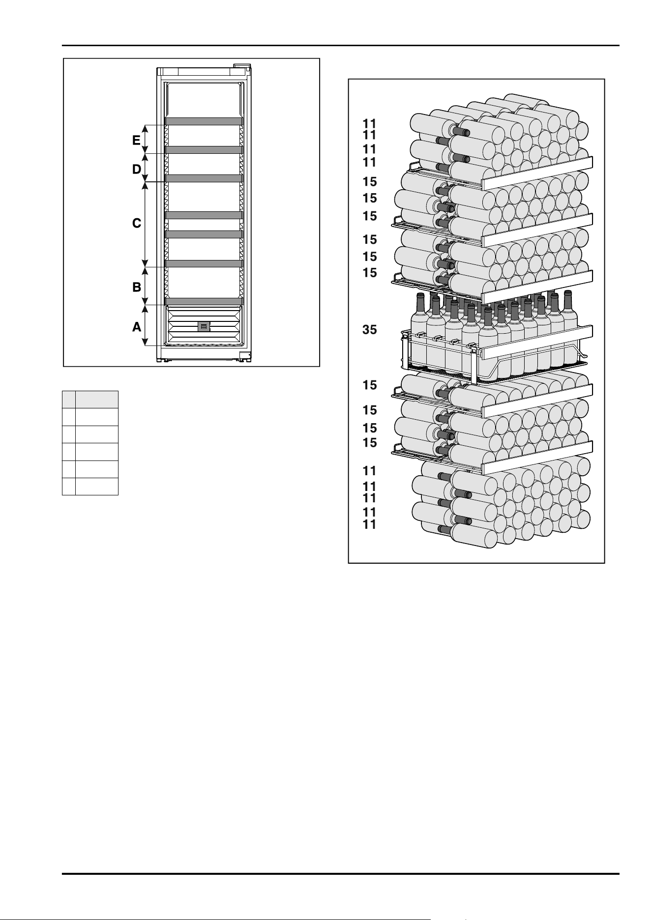
Fig. 59Grid shelf spacing
WF 52
A 260mm
B 240mm
C 540mm
D 180mm
E 180mm
6.2.3 WF 77
Fig. 60 Total 284 bottles (0.75 l Bordeaux bottles as per
standard NF H 35-124)
Storage
20 * Depending on model and options
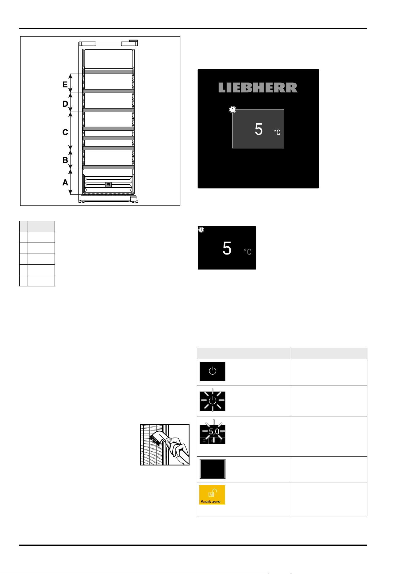
Fig.61Grid shelf spacing
WF 77
A 320mm
B 240mm
C 480mm
D 240mm
E 240mm
7 Saving energy
-
Pay attention to good ventilation. Do not cover ventilation
holes or grids.
-
Always keep the fan air slits clear.
-
Do not place the appliance in direct sunlight or near radi‐
ators or similar sources of heat.
-
If the appliance is placed directly next to an oven,
the energy consumption may increase slightly. This is
dependent on the service life and usage intensity of the
oven.
-
Energy consumption depends on the installation condi‐
tions, e.g. the ambient temperature (see 2.4 Appliance
range of use) . A warmer ambient temperature can
increase the energy consumption.
-
Open the appliance for as short a time as possible.
-
The lower the temperature is set the higher the energy
consumption.
Dust deposits increase energy consump‐
tion:
-
For refrigerators with heat exchangers
dust the metal grid on the back of the
appliance once a year.
8 Controls
8.1 Control and display elements
The display provides a quick overview of the current appli‐
ance status, the temperature setting, the status of func‐
tions and settings as well as alarm and error messages.
Operation takes place directly on the Touch & Swipe display
by swiping and touching.
Functions can be activated or deactivated and setting
values can be changed.
Fig. 62 Touch&Swipe display
(1)
Status display
8.1.1 Status display
Fig. 63 Status display
(1)
Temperature
The status display is the output display.
Navigation to the functions takes place from the status
display.
8.1.2 Display symbols
Display symbols provide information about the status of the
appliance.
Symbol
Appliance status
Standby symbol
Appliance is switched off.
Standby symbol
(flashing)
Appliance is starting up.
Temperature (flashing)
Target temperature not
yet reached. Appliance
cooling to temperature
set.
Status display (white
frame)
Appliance is locked.
Manual door opening
(yellow)
The locked door was
opened manually.
Saving energy
* Depending on model and options 21
Symbol Appliance status
Error symbol (red)
Appliance is in error
state.
Background (blue)
Active setting or active
function
Bar (increasing)
Press for 3 seconds to
activate setting.
Bar (decreasing)
Press for 3 seconds to
deactivate setting.
Symbols on the status display
8.1.3 Acoustic signals
A signal sounds in the following cases:
-
If a function or a value is confirmed.
-
If a function or a value can either not be activated or not
deactivated.
-
As soon as an error occurs.
-
If there is an alarm message.
The alarms can be switched on and off in the customer
menu.
8.2 Appliance functions
8.2.1 Notes on the appliance functions
The appliance functions are set at the factory so that your
appliance is fully functional.
Before you alter, activate or deactivate the device functions,
make sure that the following requirements are met:
❑
You have read and understood the descriptions of
how the display works. (see 4 Functionality of the
Touch&Swipe display)
❑
You have familiarised yourself with the operating and
display elements of your appliance. (see 8.1 Control and
display elements)
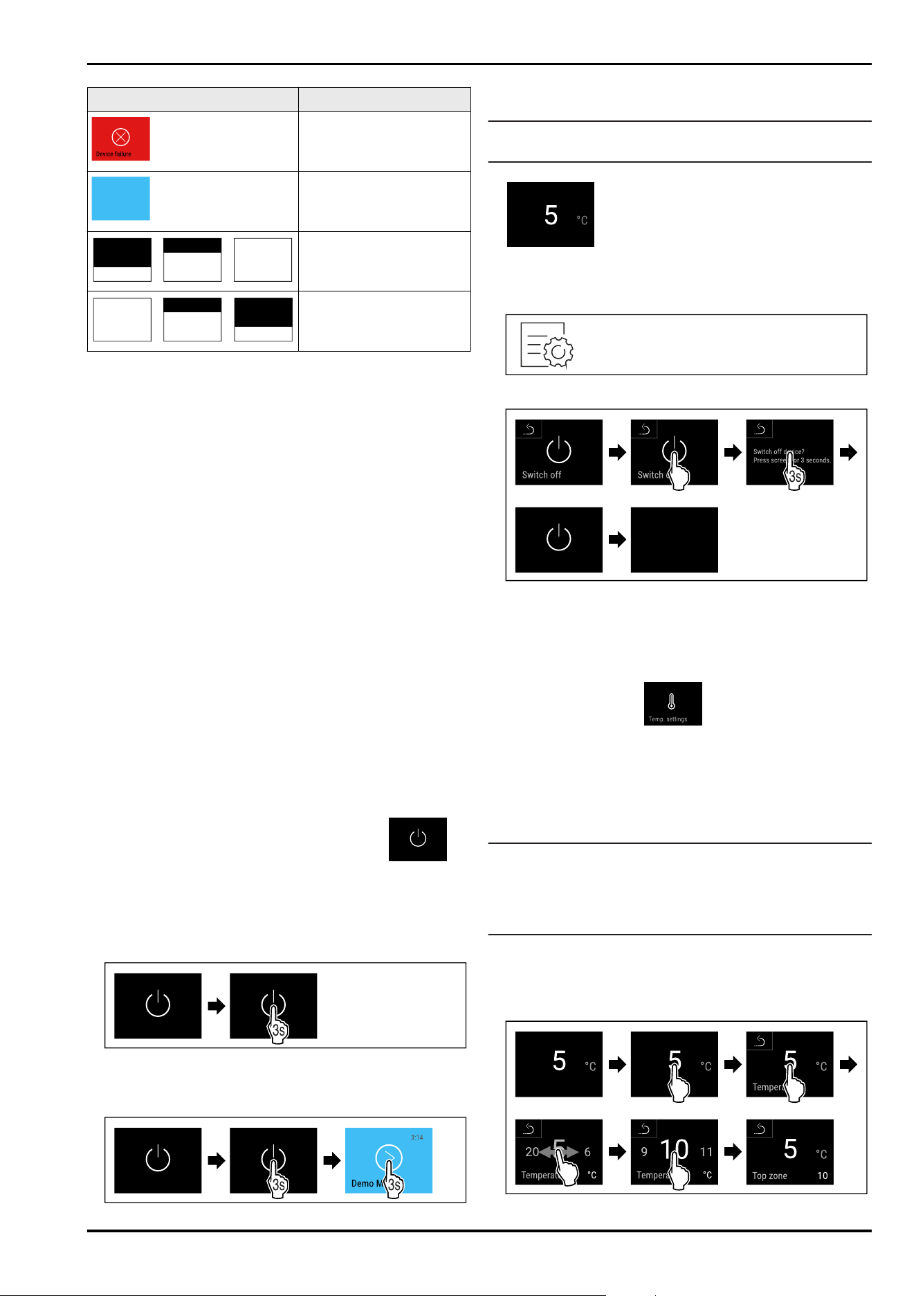
8.2.2 Switching appliance on and off
This function makes it possible to switch the entire appli‐
ance on and off.
Switching on appliance
If demo mode is not activated:
Fig.64
► Carry out action steps according to the illustration.
If demo mode is activated:
Fig.65
► Carry out action steps according to the illustration.
Note
Deactivate demo mode before the countdown has finished.
Fig. 67 Status display
▷ The temperature appears in the display.
Switching off appliance
Fig.68
Fig. 69
► Carry out action steps according to the illustration.
▷ Standby symbol is shown in the display.
▷ The display switches off automatically after around
10 minutes.
8.2.3 Temperature
The temperature depends on the following factors:
-
How often the door is opened
-
How long the door is open for
-
The room temperature of the installation site
-
The type, temperature and amount of refrigerated food
Note
The temperature may differ from the temperature displayed
in some areas of the interior.
At the correct temperature, cooled produce will keep for
longer. This avoids disposing of food unnecessarily.
Setting temperature
The following steps describe how to increase the tempera‐
ture, e.g. from 5°C to 10°C.
► Tap the temperature.
Controls
22 * Depending on model and options
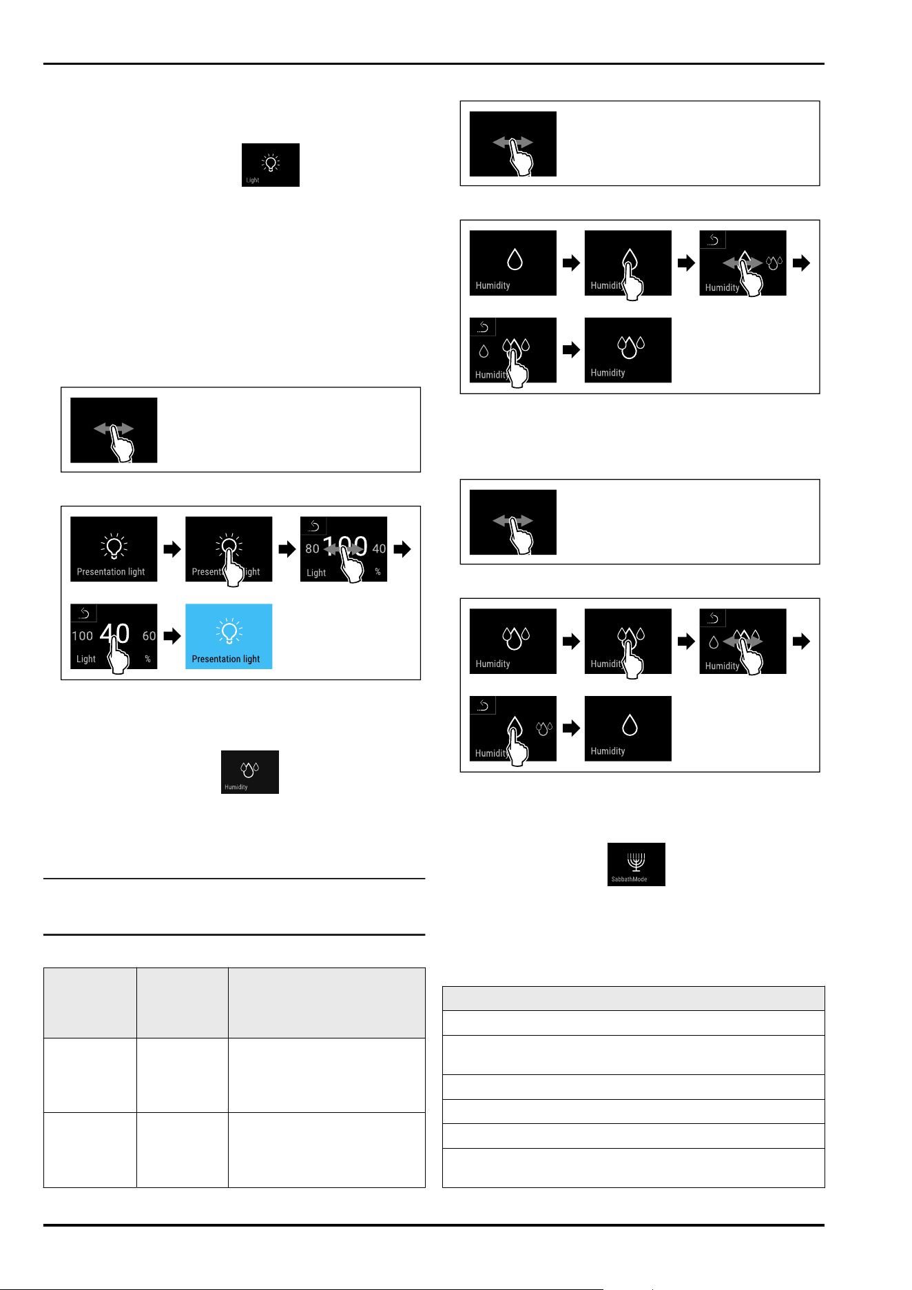
Fig.70
► Carry out action steps according to the illustration.
▷ Temperature is set.
8.2.4 Presentation light
Use this function to set the interior lighting.
The following brightness levels can be set:
-
Off
-
20%
-
40%
-
60%
-
80%
-
100% (default)
Setting the lighting
Fig.71
Fig. 72 Example illustration: Switch from 100% to 40%
► Carry out action steps according to the illustration.
▷ The brightness is set.
8.2.5 HumiditySelect
Use this function to set the humidity inside your appliance.
Setting the humidity correctly will have a positive effect
on the structure of the corks during long-term storage and
prevent them from drying out.
Note
The frequency and duration for which the door is open influ‐
ence the humidity in the appliance.
You can choose between two humidity settings:
HumiditySe‐
lect function
Temperature
setting on
the appli‐
ance
Application/energy
consumption
Standard
(preset)
10-12°C average humidity in the envi‐
ronment between 50-80%
low energy consumption of
the appliance
High 10-12°C average humidity in the envi‐
ronment < 50%
energy consumption of the
appliance increases
Increasing the humidity in the appliance
Fig.73
Fig. 74
► Carry out action steps according to the illustration.
▷ Humidity in the appliance increases.
Setting the humidity in the appliance to standard
Fig.75
Fig. 76
► Carry out action steps according to the illustration.
▷ Humidity in the appliance decreases.
8.2.6 SabbathMode
You can use this function to activate or deactivate
SabbathMode. If you activate this function, some electronic
functions are switched off. As a result, your device meets
the religious requirements for Jewish holidays such as
Sabbath and complies with STAR-K Kosher certification.
Device status when SabbathMode is active
The status display shows SabbathMode permanently.
All functions on the display are locked except for the
Deactivate SabbathMode function.
Active functions remain active.
The display remains bright when you close the door.
The interior lighting is deactivated.
Reminders are not implemented. The set time interval
stops.
Controls
* Depending on model and options 23
Device status when SabbathMode is active
Reminders and warnings are not displayed.
There is no door alarm.
There is no temperature alarm.
The Water & Ice Center is switched off.
After a power failure, the appliance returns to
SabbathMode.
Device status
Note
This appliance has certification from the “Institute for
Science and Halacha”. (www.machonhalacha.co.il)
You can find a list of STAR-K-certified appliances at
www.star-k.org/appliances.
Activating SabbathMode
Fig.77
Fig.78
► Carry out action steps according to the illustration.
▷ SabbathMode is activated.
▷ The status display shows SabbathMode permanently.
Deactivating SabbathMode
The SabbathMode is automatically deactivated after
80 hours. However, you can also deactivate SabbathMode
manually at any time:
Fig.79
► Carry out action steps according to the illustration.
▷ SabbathMode is deactivated.
▷ Door is locked automatically.
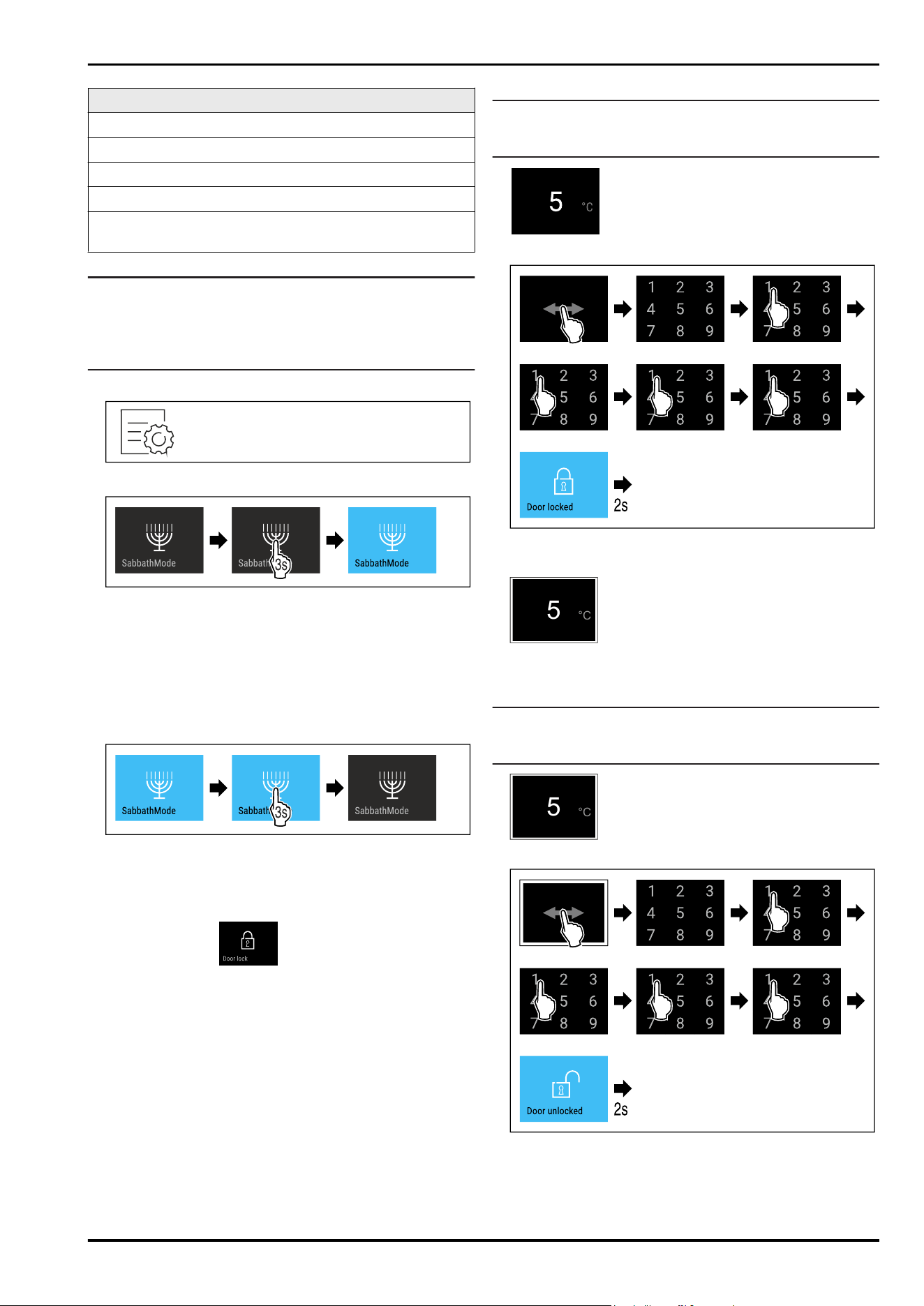
8.2.7 Door lock
The appliance is fitted with an electronic door lock. When
using the first time, the door is unlocked and you can open
it.
This function means the appliance can be secured against
the unwanted removal of items.
You have the following setting options for this:
-
Lock door using door code.
-
Unlock door using door code.
-
Change the door code. (see 8.2.9Access codes)
-
Reset the door code. (see 8.2.9Access codes)
Locking door using door code
Note
► In the following example, the factory-set PIN
code:1111 is used.
Fig. 80 Status display
Fig. 81 Locking door using door code 1111.
► Carry out action steps according to the illustration.
5
°C
Fig. 82 Status display with white border
▷ The door is locked.
Unlocking door using door code
Note
► In the following example, the factory-set PIN
code:1111 is used.
5
°C
Fig. 83 Status display with white border
Fig.84Unlock the door with door code 1111.
► Carry out action steps according to the illustration.
Controls
24 * Depending on model and options
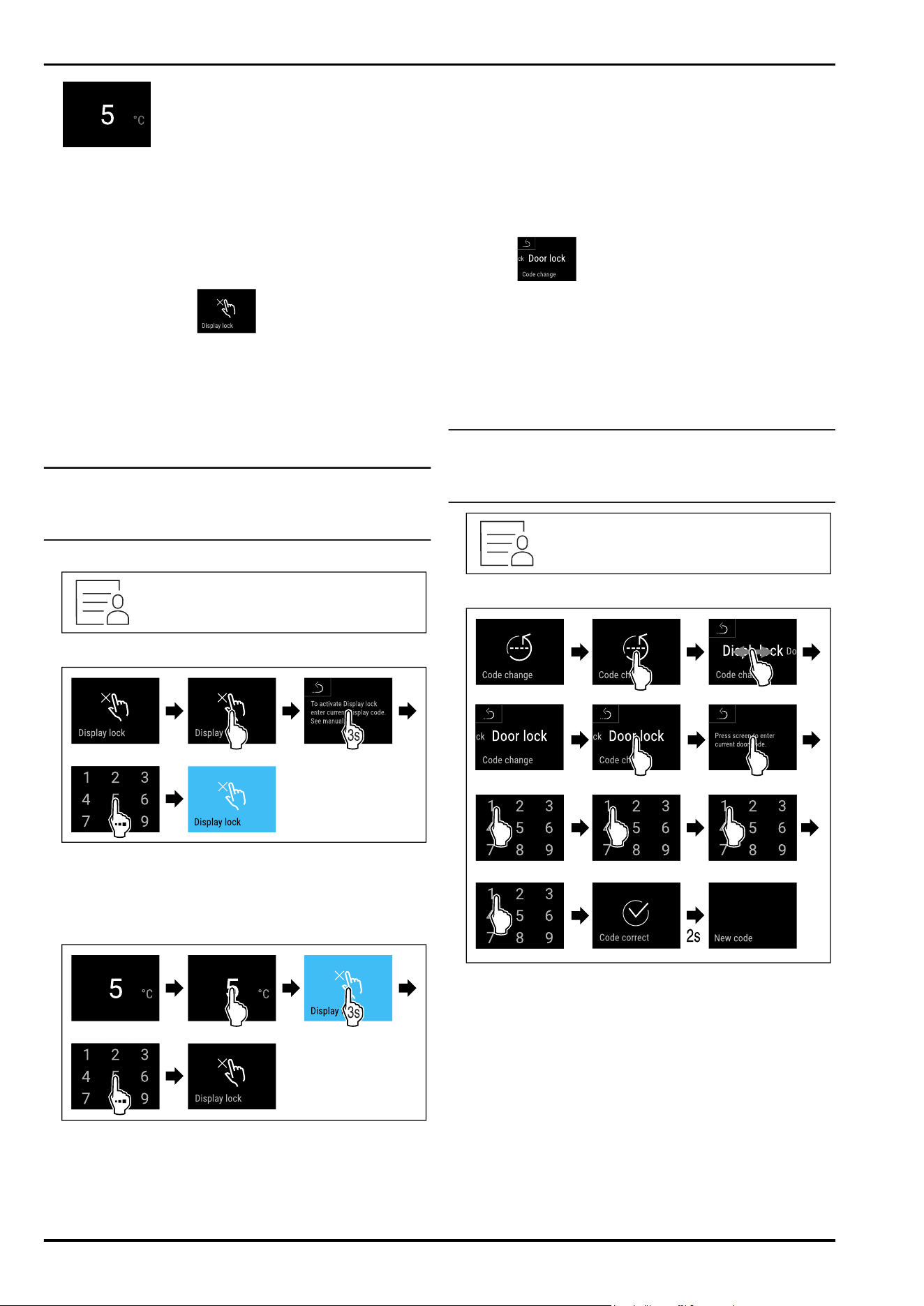
Fig. 85 Status display
▷ The door is unlocked.
Changing door code
(see 8.2.9Access codes)
Resetting door code
(see 8.2.9Access codes)
8.2.8 Display lock
This setting avoids accidental operation of the appliance.
Application:
-
Prevent settings and functions being changed uninten‐
tionally.
-
Prevent appliance being switched off unintentionally.
-
Prevent temperature being set unintentionally.
Note
Despite the display lock being activated, the door lock can
be opened and locked at any time using the PIN code
(see 8.2.9Access codes) .
Activating display lock
Fig.86
Fig. 87
► Carry out action steps according to the illustration.
▷ The display lock is activated.
▷ The status display appears.
Unlocking the display for a short time
Fig.88
► Carry out action steps according to the illustration.
▷ The display lock is deactivated.
▷ The status display appears.
8.2.9 Access codes
Various settings are possible.
Application:
-
Changing the door code.
-
Resetting the door code.
-
Changing the display lock code.
-
Resetting the display lock code.
Door code
Changing door code
The setting allows the door code for the door lock to be
changed.
The setting is made in three stages:
- Entering the old door code
- Entering the new door code
- Confirming the new door code
Note
► In the following example, the default factory set door
code 1111 is changed.
► The new door code is:2345
Fig.89
Fig.90
► Carry out action steps according to the illustration.
▷ Entry of the old door code successful.
Controls
* Depending on model and options 25
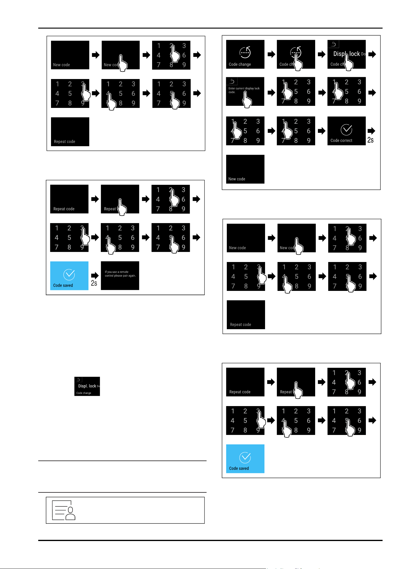
Fig. 91
► Carry out action steps according to the illustration.
▷ Entry of the new door code successful.
Fig.92
► Carry out action steps according to the illustration.
▷ Confirmation of the new door code successful.
▷ The door code has been changed.
Resetting door code
Door code forgotten or not known.
► Reset appliance to factoy settings. (see 8.2.20 Resetting
to factory settings )
▷ The appliance is reset to the original settings.
▷ The factory setting for the door code is:1111
Display lock
Changing display lock code
This setting allows the code for the display lock to be
changed.
The setting is made in 3 stages:
- Entering of old code
- Entering of new code
- Confirming of new code
Note
► In the following example, the default factory-set
code1111 is changed.
► The new code is:2345
Fig. 93
Fig. 94
► Carry out action steps according to the illustration.
▷ Entry of the old code successful.
Fig.95
► Carry out action steps according to the illustration.
▷ Entry of the new code successful.
Fig.96
► Carry out action steps according to the illustration.
▷ Confirmation of the new code successful.
▷ The code has been changed.
Resetting display lock code
Code forgotten or not known.
Controls
26 * Depending on model and options
► Reset appliance to factory settings. (see8.2.20 Resetting
to factory settings )
▷ The appliance is reset to the original settings.
▷ The factory-set code is:1111
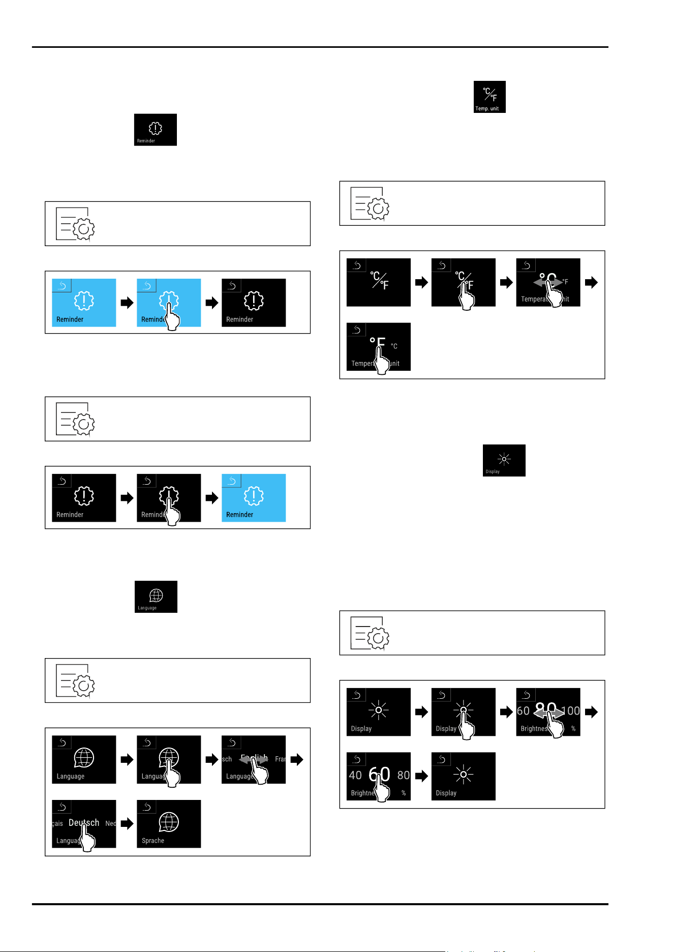
8.2.10 Reminder
This function allows you to activate or deactivate the
reminder to change theFreshAir activated charcoal filter.
Deactivating the reminder
Fig.97
Fig.98
► Carry out steps according to the illustration.
▷ Reminder is deactivated.
Activating the reminder
Fig.99
Fig. 100
► Carry out steps according to the illustration.
▷ Reminder is activated.
8.2.11 Language
This setting allows the display language to be set.
Setting language
Fig. 101
Fig. 102
► Carry out action steps according to the illustration.
▷
The selected language is set.
8.2.12 Temperature unit
Use this function to set the temperature unit. You can set
degrees Celsius or degrees Fahrenheit as the temperature
unit.
Setting the temperature unit
Fig. 103
Fig. 105 Example illustration: Switch from degreesCelsius
to degrees Fahrenheit.
► Carry out action steps according to the illustration.
▷ The temperature unit is set.
8.2.13 Display brightness
Use this function to set the display brightness in stages.
You can select the following brightness levels:
-
20%
-
40%
-
60%
-
80%
-
100 % (pre-setting)
Setting the brightness
Fig. 106
Fig. 107 Example illustration: Switch from 80 % to 60%.
► Carry out action steps according to the illustration.
▷ The brightness is set.
Controls
* Depending on model and options 27
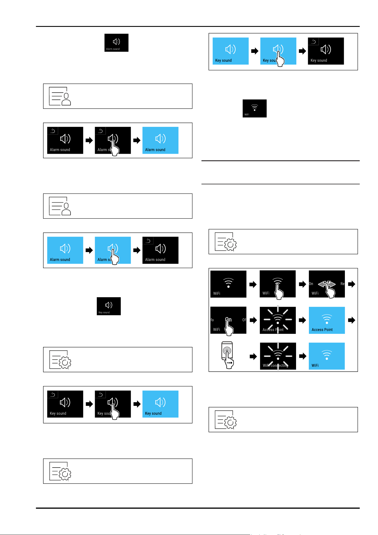
8.2.14 Alarm Sound
This function enables all alarm sounds, such as door
alarms, to be switched on and off.
Activating Alarm Sound
Fig. 108
Fig. 109
► Carry out action steps according to the illustration.
▷ Alarm Sound is activated.
Deactivating Alarm Sound
Fig. 110
Fig.111
► Carry out action steps according to the illustration.
▷ Alarm Sound is deactivated.
8.2.15 Key Sound
This function makes it possible to switch all button sounds,
confirmation sounds, and the startup sound on and off.
Activating Key Sound
Fig.112
Fig.113
► Carry out action steps according to the illustration.
▷ Key Sound is activated.
Deactivating Key Sound
Fig. 114
Fig. 115
► Carry out action steps according to the illustration.
▷ Key Sound is deactivated.
8.2.16 WiFi
Use this function to connect your appliance to WiFi. You can
then operate it via the SmartDevice app on a mobile device.
You can also use this function to disconnect or reset the
WiFi connection.
More information on the SmartDevice: (see 2.3 SmartDevice)
Note
The SmartDevice function is not available in the following
countries: Russia, Belarus, Kazakhstan.
Establishing the WiFi connection for the first time
Make sure that the following requirements are fulfilled:
❑
You have installed the SmartDevice app (see
apps.home.liebherr.com).
❑
Registration in the SmartDevice app is completed.
Fig. 116
Fig.117
► Carry out action steps according to the illustration.
▷ Connection is established.
Disconnecting from the WiFi
Fig. 118
Controls
28 * Depending on model and options
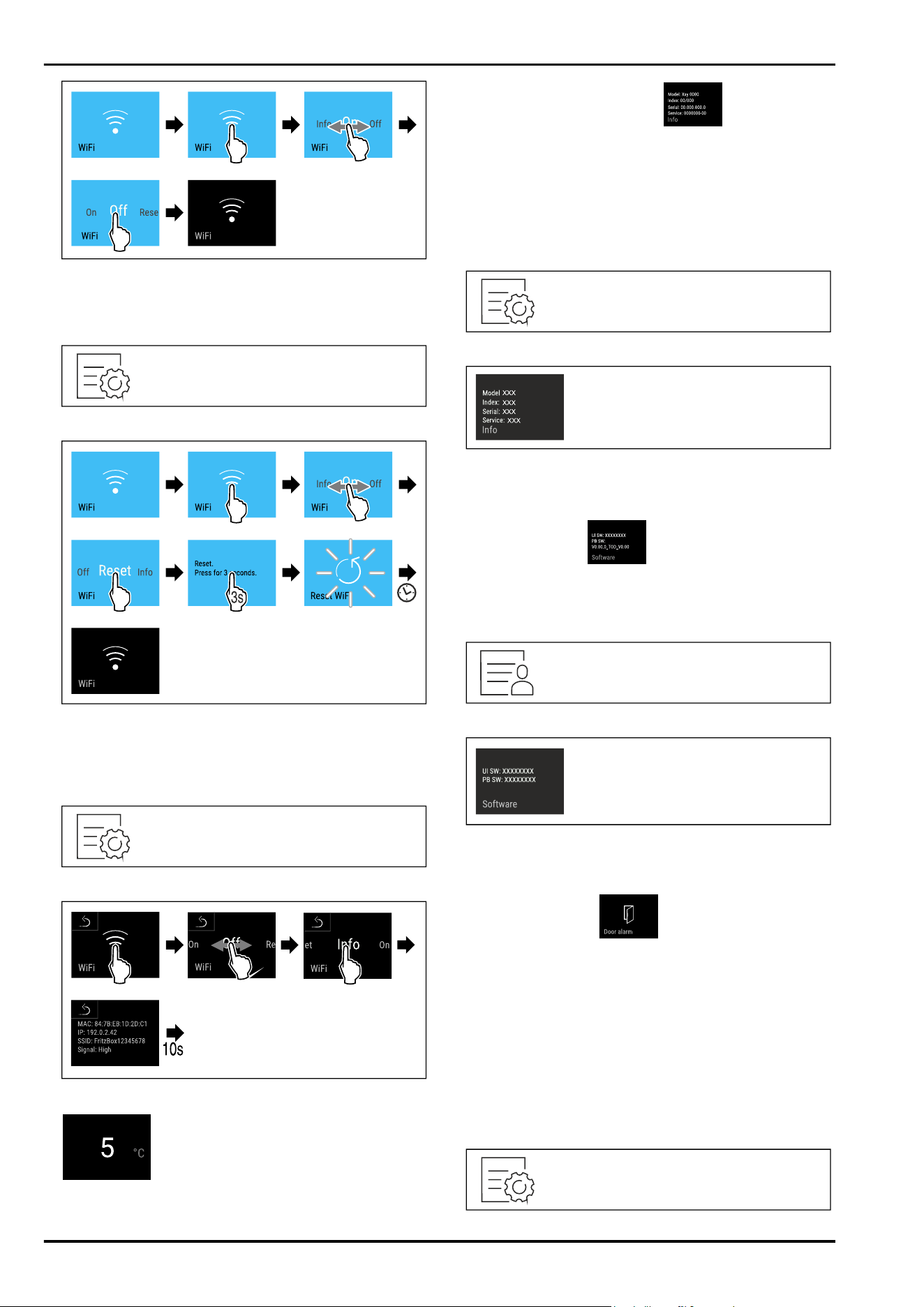
Fig. 119
► Carry out action steps according to the illustration.
▷ There is no connection.
Resetting the WiFi connection
Fig.120
Fig.121
► Carry out action steps according to the illustration.
▷ WiFi connection and other WiFi settings are reset to
factory settings.
Showing information about the WiFi connection
Fig.122
Fig.123
Fig. 124 Status display
► Carry out action steps according to the illustration.
8.2.17 Device information
Use this function to indicate the model name, index, serial
number and service number of your device. You will need
the device information when you contact customer service.
(see11.4 Customer Service)
This function also opens the Advanced menu. (see 4 Func‐
tionality of the Touch&Swipe display)
Indicating the device information
Fig.125
Fig. 126
► Carry out action steps according to the illustration.
▷ Display indicates device information.
8.2.18 Software
Use this function to indicate the software version of your
device.
Indicating the software version
Fig.127
Fig.128
► Carry out action steps according to the illustration.
▷ Display indicates software version.
8.2.19 Door alarm
Use this function to activate or deactivate the door alarm.
The door alarm sounds if the door is open for too long. The
door alarm is activated on delivery. You can set how long
the door may be open before the door alarm sounds.
The following values can be set:
-
1 minute
-
2 minutes
-
3 minutes
-
Off
Setting the door alarm
Controls
* Depending on model and options 29
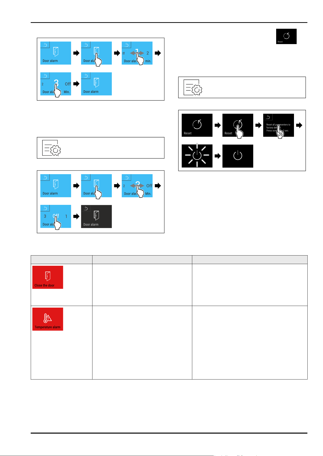
Fig.129
Fig. 130 Example illustration: Change door alarm from
1 minute to 3 minutes.
► Carry out action steps according to the illustration.
▷ The door alarm is set.
Deactivating the door alarm
Fig.132
Fig.133
► Carry out action steps according to the illustration.
▷ The door alarm is deactivated.
8.2.20 Resetting to factory settings
Use this function to reset all settings to factory defaults.
All settings you have made so far are reset to their original
settings.
Performing a reset
Fig.134
Fig.135
► Carry out action steps according to the illustration.
▷ Device is reset.
▷ Device is switched off.
► Restart the device. (see 5.1 Switching on appliance (first
use))
8.3 Message
8.3.1 Warnings
Warnings are issued by means of an acoustic signal and
visually via a symbol on the display. The signal gets louder
until the warning is acknowledged.
Message (red)
Cause Remedy
Door open
This message appears if the door is open
for too long.
Close the door.
Tap briefly.
Alarm is stopped.
Note
The time until the message appears can be set.
(see 8.2.19Door alarm )
Temperature alarm
This message appears if the temperature
does not match the set temperature.
Reasons for differences in temperature
can be:
Warm produce for cooling has been placed
inside.
Too much warm air has got in while you
were sorting out the freezer or removing
items.
The power was cut off for a prolonged
period.
Tap briefly.
Information about errors and appliance status are
displayed.
Tap briefly.
Warmest/coldest temperature, date and time are
displayed.
Tap briefly.
The status screen is displayed.
The current temperature and the alarm symbol
flash red until the set temperature is reached.
Check the quality of the refrigerated goods.
Controls
30 * Depending on model and options
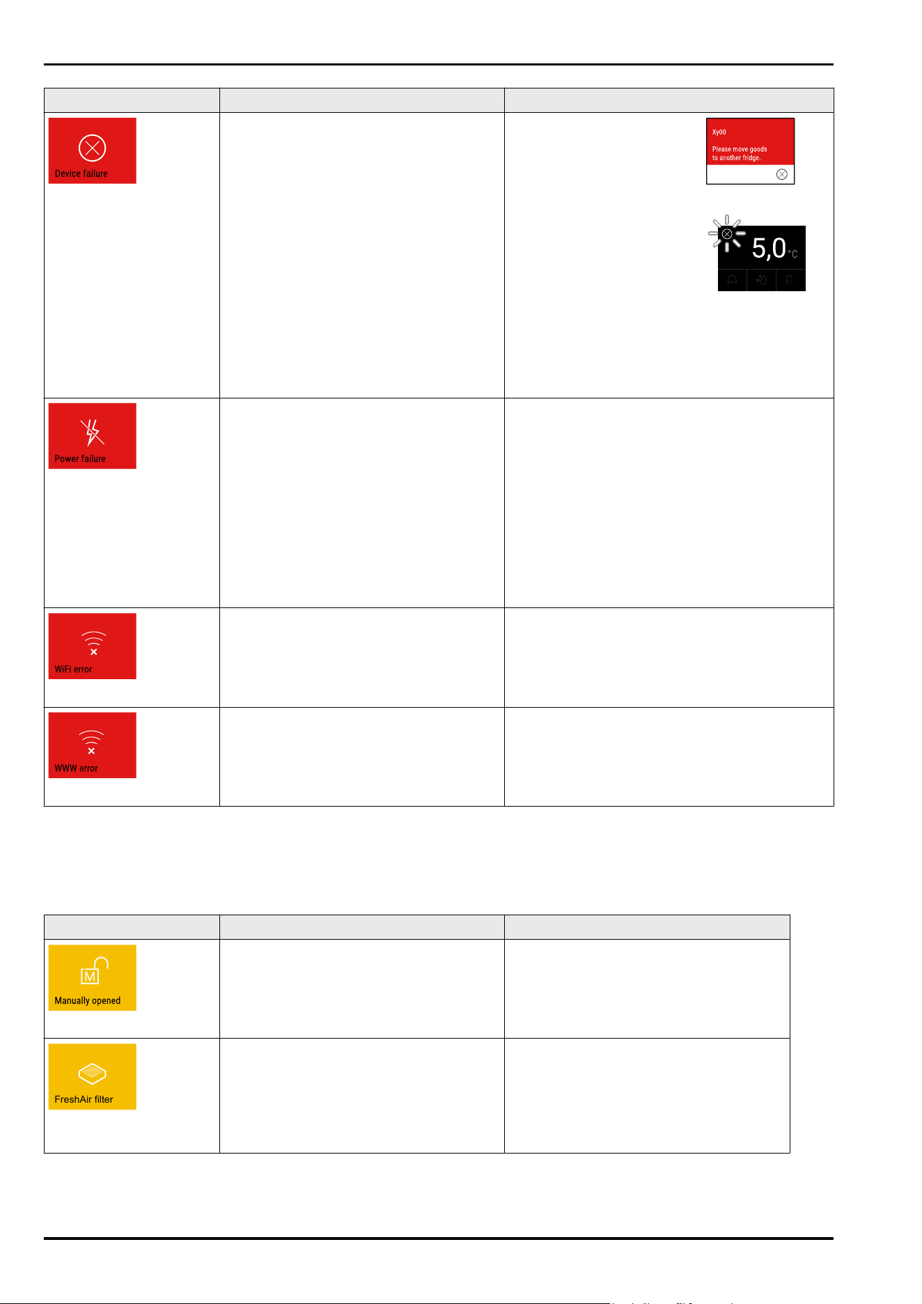
Message (red) Cause Remedy
Error
The appliance is faulty, there is an appli‐
ance error or a component of the appliance
has a fault.
Store the cooled produce
elsewhere.
Tap briefly.
The error code (e.g. BT021) is
displayed.
Tap briefly.
A further error code is
displayed if there is one
or
Status screen is displayed
with flashing error symbol.
Swiping or tapping the display will show the error
code(s) again.
Make a note of error code(s) and contact
Customer Service. (see11.4 Customer Service)
Power cut
The message appears following an inter‐
ruption to the electricity supply.
Tap briefly.
Battery’s state of charge, information about
errors and appliance status are displayed
Tap briefly.
The warmest temperature and the period of
power interruptions are displayed.
Tap briefly.
The status screen is displayed.
The current temperature and the alarm symbol
flash red until the set temperature is reached.
Check the quality of the refrigerated goods.
WiFi error
Wi-Fi connection is interrupted. Check connection.
Press briefly.
Alarm is stopped.
WWW error, WiFi
This message appears if there is no
internet connection via WiFi.
Check connection.
Press briefly.
Alarm is stopped.
8.3.2 Reminders
Reminders appear when you are being asked to do some‐
thing. The are issued by means of an acoustic signal and
visually via a symbol on the display. Acknowledge the
message by pressing the confirmation button.
Message (yellow) Cause Remedy
Manually opened
This message appears if a door which
has been locked electronically is manually
opened.
Close the door.
Press briefly.
Enter the door code to close it again.
Reminder is closed.
FreshAir filter
ReplaceFreshAir acti‐
vated charcoal filter
The message appears every 6 months. ReplaceFreshAir activated charcoal filter,
Press briefly.
Reminder is closed.
Controls
* Depending on model and options 31
9 Features
9.1 Safety lock
The appliance door is fitted with an electronic lock.
Application:
-
Lock and unlock with door code. (see 8.2.7Door lock )
-
Door locks automatically after a power failure (cannot be
deactivated).
9.1.1 Emergency unlocking
If there is a power failure, the door can be opened with the
emergency release key.
Fig.136
► Insert the emergency release key in the specified position
Fig.136(A) ≈ 100mm.
► Insert the emergency release key Fig. 136 (1) between the
door and the body of the appliance from above to the end
stop.
► Pull the emergency release key towards the hinge.
Fig.136(2)
▷ The lock is unlocked. You can open the door.
9.2 Labels
Description labels as accessories can be purchased from
your specialist dealer. You can use these to note the types
of wine that are stored in the respective compartment.
Fig.137
► Attach the label from above.
9.3 Labels
Description labels as accessories can be purchased from
your specialist dealer. You can use these to note the types
of wine that are stored in the respective compartment.
Fig.138
► Attach the label from above.
10 Maintenance
10.1 FreshAir activated carbon filter
Wine is constantly developing according to its ambient
conditions, so air quality is essential for preservation.
The FreshAir activated charcoal filter guarantees optimal air
quality.
❑
Change the activated charcoal filter every 6 months.
❑
Dispose of the activated charcoal filter with regular
household waste.
Note
FreshAir activated charcoal filters can be purchased
from the Liebherr-Hausgeräte store at home.liebherr.com/
shop/de/deu/zubehor.html.
10.1.1 Replacing the FreshAir activated char‐
coal filter
Fig. 139
► Pull off the cover.
Features
32 * Depending on model and options
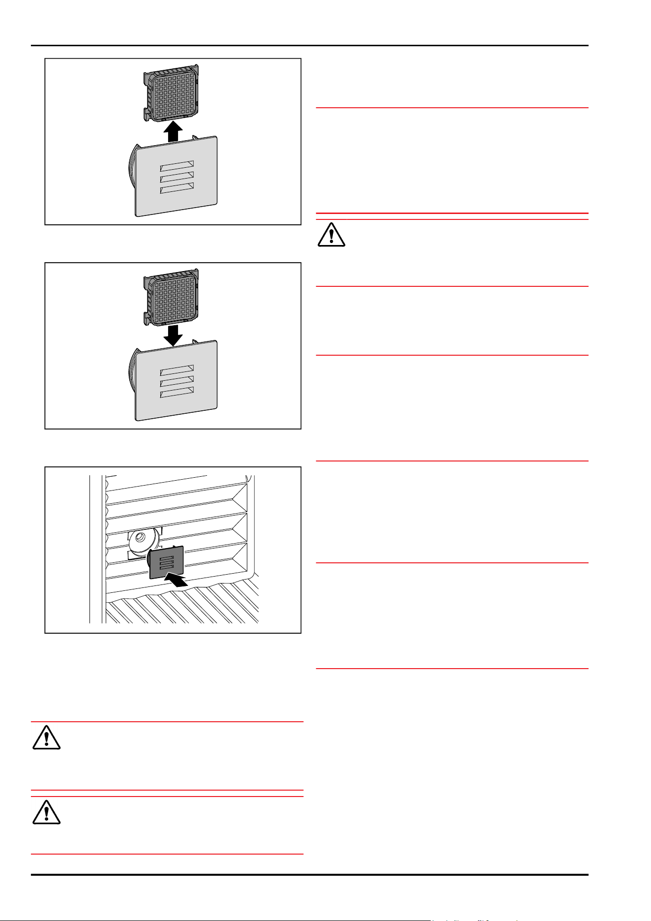
Fig. 140
► Pull out the filter.
Fig. 141
► Insert the new filter.
Fig. 142
► Set the cover back in place.
10.2 Cleaning the appliance
10.2.1 Ready
WARNING
Danger of electric shock!
► Remove the refrigerator connector or interrupt the power
supply.
WARNING
Risk of fire
► Do not damage the refrigeration circuit.
► Empty the appliance.
► Remove mains connector.
10.2.2 Clean the housing
NOTICE
Improper cleaning!
Damage to the appliance.
► Only use soft cleaning cloths and ph-neutral all-purpose
cleaners.
► Do not uses abrasive sponges or steel wool which may
cause scratches.
► Do not use any sharp or abrasive cleaning agents, nor
any that contain sand, chloride or acid.
WARNING
Risk of injury and damage as a result of hot steam!
Hot steam can lead to burns and can damage the surfaces.
► Do not use any steam cleaners!
►
Wipe the housing down with soft, clean cloth. If very
dirty, use lukewarm water with a neutral cleaner. Glass
surfaces can also be cleaned with glass cleaner.
10.2.3 Cleaning the interior
NOTICE
Improper cleaning!
Damage to the appliance.
► Only use soft cleaning cloths and ph-neutral all-purpose
cleaners.
► Do not uses abrasive sponges or steel wool which may
cause scratches.
► Do not use any sharp or abrasive cleaning agents, nor
any that contain sand, chloride or acid.
► Plastic surfaces: clean by hand with a soft clean cloth,
lukewarm water and a little detergent.
► Metal surfaces: clean by hand with a soft clean cloth,
lukewarm water and a little detergent.
► Drain hole: remove deposits using a thin item (for
example a cotton bud).
10.2.4 Cleaning the equipment
NOTICE
Improper cleaning!
Damage to the appliance.
► Only use soft cleaning cloths and ph-neutral all-purpose
cleaners.
► Do not uses abrasive sponges or steel wool which may
cause scratches.
► Do not use any sharp or abrasive cleaning agents, nor
any that contain sand, chloride or acid.
Cleaning with a damp, lint-free cloth:
- Bottle shelf
► Clean the equipment.
10.2.5 After cleaning
► Wipe the appliance and the components dry.
► Connect and switch on the appliance.
► Repeat cleaning regularly.
Maintenance
* Depending on model and options 33
11 Customer help
11.1 Technical specifications
Temperature range
Cooling 5°C to 20°C
Maximum loading weight for
the bottle rack
Bottle shelf 60 kg
Bottle rack with
telescopic rails
25 kg
Lighting
Class
1
Light source
This product contains one or more energy
efficiency class F light sources.
LED
1
The appliance may contain light sources with different
energy efficiency classes. The lowest energy efficiency class
is indicated.
For appliances with a WiFi connection:
Frequency specification
Frequency band 2.4GHz
Maximum radiated
power
< 100 mW
Purpose of the
wireless equipment
Integration in the local WiFi network
for data communication
11.2 Operating noises
The appliance makes different noises when it is on.
-
At higher temperatures the appliance uses less energy
but works for longer. It is quieter.
-
At lower temperatures the food is cooled faster. It is
louder.
Examples:
•
Functions on (see8.2Appliance functions)
•
Fan running
•
Food recently added
•
High ambient temperature
•
Door open for a while
Noise
Possible cause Type of noise
Bubbling and
splashing
Coolant flowing
into the cooling
circuit.
Normal operating
noise
Noise Possible cause Type of noise
Hissing Coolant sprays
into the cooling
circuit.
Normal operating
noise
Humming The appliance
is cooling. The
volume depends
on the cooling
output.
Normal operating
noise
Humming and
rustling
The fan is running. Normal operating
noise
Clicking Components are
switched on and
off.
Normal switching
noise
Rattling or
humming
Valves or flaps are
working.
Normal switching
noise
Noise Possible
cause
Type of noise Lifting
Vibration Improper
setup
Defective
noise
Level the
appliance
using the
adjustable
feet.
Rattling Components,
items inside
the appliance
Defective
noise
Secure
components.
Leave
enough
space
between the
items.
11.3 Technical fault
Your appliance is designed and built to ensure it works reli‐
ably and has a long service life. In the unlikely event that
a fault occurs during operation, please check whether it is
due to an operating error. If so, you will be charged for the
callout and repair costs even if it falls within the warranty
period.
You can fix the following faults yourself.
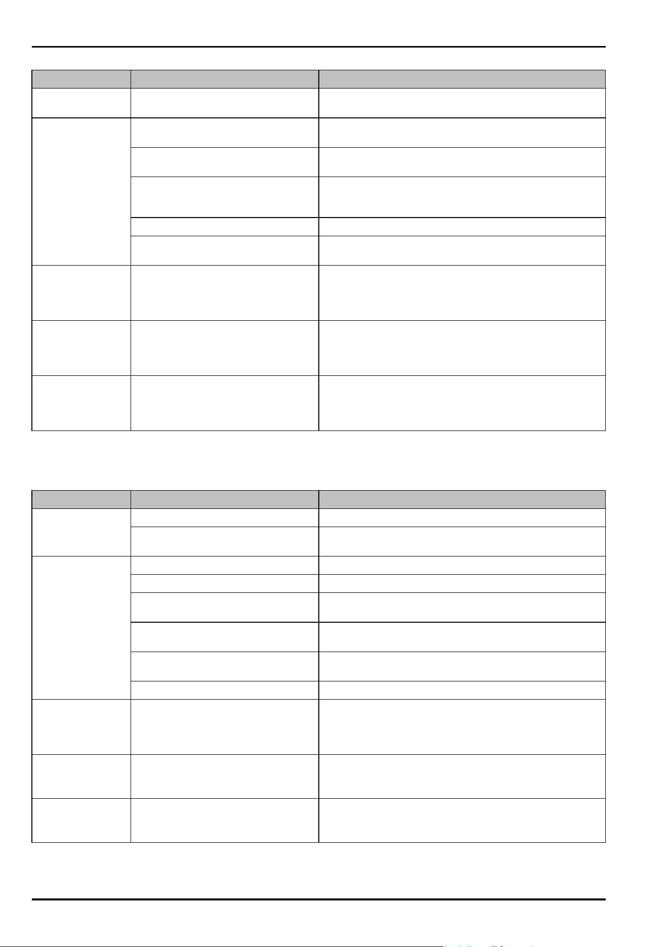
11.3.1 Appliance function
Defect
Cause Remedy
The appliance is
not working.
→ The appliance is not switched on. ► Switch the appliance on.
→ The power plug is not properly
plugged into the socket.
► Check the power plug.
→ There is something wrong with the
power outlet fuse.
► Check the fuse.
→ Power cut ► Keep the appliance closed.
Customer help
34 * Depending on model and options
Defect Cause Remedy
→ The IEC socket is not plugged into
the appliance correctly.
► Check the IEC socket.
Temperature is not
cold enough.
→ The appliance door is not closed
properly.
► Close the appliance door.
→ The ambient temperature is too
high.
► Problem solution: (see2.4 Appliance range of use)
→ The appliance was opened too
many times or for too long.
► Wait to see if the required temperature corrects itself.
If not, contact Customer Service. (see 11.4 Customer
Service)
→ The temperature is set incorrectly. ► Turn down the temperature and check after 24 hours.
→ The appliance is too close to a heat
source (oven, radiator, etc).
► Move the appliance or the heat source.
The door seal is
defective or needs
to be replaced for
another reason.
→ The door seal can be replaced. It
can be replaced without the need
for special tools.
► Contact Customer Service. (see11.4 Customer Service)
The appliance
builds up too much
ice or condensa‐
tion.
→ The door seal may have slipped out
of its groove.
► Check that the door seal is well fitted in the groove.
The exterior
surfaces of the
appliance are
warm.*
→ The heat of the refrigeration circuit
is used to avoid condensation.
► This is normal.
11.3.2 Features
Defect Cause Remedy
Water & Ice Center
does not function.
→ Control panel is locked. ► Deactivate the child lock on the Water & Ice Center.
→ The Water & Ice Center is deacti‐
vated.
► Activate the Water & Ice Center.
The Water & Ice
Center does not
dispense any ice
cubes.
→ Ice cubes are used up. ► Wait until new ice cubes are produced.
→ Doors are open. ► Close the doors.
→ Ice storage compartment is not
completely closed.
► Push the ice storage compartment completely in.
→ Ice cube channel on the inside of
the door is blocked.
► Remove the ice cubes completely from the channel.
→ Ice production function is deacti‐
vated.
► Activate the Ice production function.
→ The water connection is not open. ► Open the water connection.
The Water &
Ice Center does
not dispense any
water.
→ The water connection is not open. ► Open the water connection.
Water flow at the
Water & Ice Center
is uneven.
→ There is air in the water system. ► Bleed the water system.
The MoodLight in
the output area
does not light up.
→ The MoodLight is deactivated. ► Activate the MoodLight.
Customer help
* Depending on model and options 35
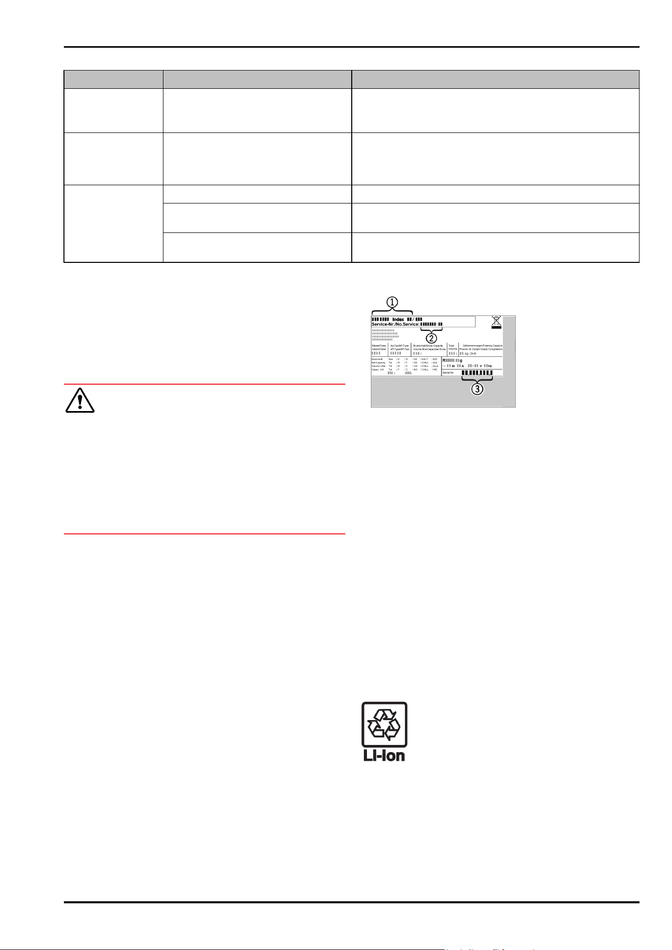
Defect Cause Remedy
The MoodLight of
the recessed grips
does not light up.
→ The MoodLight is deactivated. ► Activate the MoodLight.
Mould on the wine
bottles
→ Similar to other types of bearing,
a slight layer of mould can form
depending on the type of adhesive
used for the label.
► Remove any adhesive residues.
The internal light
does not come on.
→ The appliance is not switched on. ► Switch the appliance on.
→ The door was open for longer than
15 minutes.
► Interior lighting switches off automatically after
about 15 minutes when the door is open.
→ The LED interior light is faulty or
the lid is damaged.
► Contact Customer Service. (see11.4 Customer Service)
11.4 Customer Service
First check whether you can rectify the fault yourself
(see 11 Customer help) . If you cannot rectify the problem,
contact Customer Service.
You can find the address in the enclosed brochure “Liebherr-
Service” or at home.liebherr.com/service.
WARNING
Unprofessional repair!
Injuries.
► Have any repairs and action - not expressly specified -
on the appliance and mains cable carried out by service
personnel only. (see 10 Maintenance)
► A damaged mains cable may only be replaced by the
manufacturer, the manufacturer’s Customer Service or a
similarly qualified person.
► In the case of appliances with an IEC connector, the
change may be made by the customer.
11.4.1 Contacting Customer Service
Make sure that the following appliance information is avail‐
able:
❑
Appliance name (model and index)
❑
Service no. (Service)
❑
Serial no. (S no.)
► Call up the appliance information via the display.
-or-
► Refer to the type plate for appliance information.
(see 11.5 Model plate)
► Note down the appliance information.
► Notify customer service: Report errors and the appliance
information.
▷ This will help us to provide you with a faster, more accu‐
rate service.
► Follow further instructions from Customer Service.
11.5 Model plate
The type plate is located on the bottom left of the inside of
the appliance.
Fig. 143
(1) Appliance description (3) Serial no.
(2) Service no.
► Note the data on the model plate.
12 Shutting down
► Empty the appliance.
► Empty the ice storage compartment completely.
► Deactivate the Water & Ice Center.
► Switch off appliance. (see 8.2.2 Switching appliance on
and off )
► Pull the mains plug out of the socket.
► Remove the IEC socket if required: Pull the IEC socket out
of the appliance plug and move it to the left and right at
the same time.
► Clean appliance. (see 10.2Cleaning the appliance)
► Leave the door open, so that no unpleasant odours arise.
13 Disposal
13.1 Preparing appliance for disposal
Liebherr uses batteries in some of its appli‐
ances. In the EU, for environmental reasons,
legislation obliges the end user to remove
these batteries before disposing of old appli‐
ances. If your appliance contains batteries, a
corresponding notice is attached.
Lamps If you can remove the lamps yourself without
destroying them, also remove these before
disposal.
► Take the appliance out of operation.
► If possible: remove lamps without destroying them.
Shutting down
36 * Depending on model and options
13.2 Disposing of the appliance in an
environmentally friendly manner
The appliance still contains
valuable materials and must
be disposed of separately from
unsorted municipal waste.
Dispose of batteries separately
from the old appliance. To do
this, you can return the batteries
free of charge to retailers as
well as recycling centres and
collection centres for recyclable
materials.
Lamps Dispose of removed lamps
via the respective collection
systems.
For Germany: You can dispose of the appli‐
ance free of charge via the
class 1 collection containers
at the local recycling and
recyclable material collection
centres. When purchasing a new
fridge/freezer, if the sales area
> 400 m
2
, retailers will also take
back the old appliance free of
charge.
WARNING
Leaking coolant and oil!
Fire. The coolant contained in the appliance is eco-friendly,
but also flammable. The oil contained in the appliance
is flammable. Escaping coolant and oil can ignite if the
concentration is high enough and in contact with an
external heat source.
► Do not damage the pipelines of the coolant circuit and
the compressor.
► Observe the notes on transporting the appliance.
(see 3.3 Transporting the appliance)
► Transport the appliance without damaging it.
► Dispose of batteries, lamps and the appliance according
to the above specifications.
Disposal
* Depending on model and options 37

home.liebherr.com/fridge-manuals
ORIGINAL OPERATOR'S MANUAL
Issue date: 20250930
Part number index:7083360-00
Liebherr-Hausgeräte GmbH
Memminger Straße 77-79
88416Ochsenhausen
Deutschland